Embed Size (px)
Citation preview

Introduction
The Configuring VLANs and Trunks module provides you with the instructions and Cisco hardware to
develop your hands on skills in configuring layer 2 technologies VLANs and trunking. This module
includes the following exercises:
1) Configure and verify VLANs
2) Configure and verify a trunk link
Lab Diagram
During your session you will have access to the following lab configuration. Depending on the
exercises you may or may not use all of the devices, but they are shown here in the layout to get an
overall understanding of the topology of the lab.
Connecting to your lab
In this module you will be working on the following equipment to carry out the steps defined in each
exercise.
NYACCESS1
NYCORE1
Internet
Frame-RelayWAN
PLABCSCO01Cisco Tools Server
NYACCESS1Cisco 2960-24Switch
NYCORE1Cisco 3750-24PSSwitch
NYCORE2Cisco 3750-24PSSwitch
NYWAN1Cisco 2811 Router
NWRKWAN1
LDNWAN1
NYEDGE1Cisco 2811 Router
NYEDGE2Cisco 2811 Router
Fas0/1
172.16.16.0/24
172.14.0.0/24
ISP1172.14.0.3/24
ISP2172.14.0.4/24
Fas0/0 Fas0/0
Fas0/1 Fas0/1
Fas1/0/1 Fas1/0/1Fas1/0/2Fas0/0
Fas1/0/23
Fas1/0/24
Fas1/0/22 Fas1/0/22
Fas0/24 Fas0/23
Fas0/1Lab Nic192.168.16.10/24
Fas1/0/12
CiscoIP Phone

NYCORE2
Each exercise will detail which terminal you are required to work on to carry out the steps.
During the boot up process an activity indicator will be displayed in the device name tab:
Black - Powered Off
Orange - Working on your request
Green - Ready to access
If the remote terminal is not displayed automatically in the main window (or popup) click the
Connect icon located in the tools bar to start your session.
Copyright Notice
This document and its content is copyright of Practice-IT - © Practice-IT 2013. All rights reserved.
Any redistribution or reproduction of part or all of the contents in any form is prohibited other than
the following:
1) You may print or download to a local hard disk extracts for your personal and non-commercial use
only.
2) You may copy the content to individual third parties for their personal use, but only if you
acknowledge the website as the source of the material. You may not, except with our express
written permission, distribute or commercially exploit the content. Nor may you transmit it or store
it in any other website or other form of electronic retrieval system.

Exercise 1 – Configuring and verify VLANs
In this exercise you will perform the tasks required to create and verify VLANs on a Cisco Switch.
Please refer to your course material or use your preferred search engine to gain an understanding of
these tasks.
Creating your first VLAN
In this lab you will notice that we automatically power on some of the lab devices. This is because we
are pre-applying some configuration to save you some time but it will take a few moments for the
devices to power up, if you completed the module Configure and verify initial switch configuration
you may remember how long it took for the switches to power on, the Cisco 3750 series (NYCORE1
and NYCORE2) take even longer because there is a stack election that also occurs which takes 30
seconds.
Step 1
Connect to NYCORE1 in the lab. Use the show vlan command to observe the VLAN configuration
(vlan database) on the switch:
NYCORE1#show vlan
VLAN Name Status Ports
---- -------------------------------- --------- -------------------------------
1 default active Fa1/0/1, Fa1/0/2, Fa1/0/3
Fa1/0/4, Fa1/0/5, Fa1/0/6
Fa1/0/7, Fa1/0/8, Fa1/0/9
Fa1/0/10, Fa1/0/11, Fa1/0/12
Fa1/0/13, Fa1/0/14, Fa1/0/15
Fa1/0/16, Fa1/0/17, Fa1/0/18
Fa1/0/19, Fa1/0/20, Fa1/0/21
Fa1/0/23, Fa1/0/24, Gi1/0/1
Gi1/0/2
1002 fddi-default act/unsup
1003 token-ring-default act/unsup
1004 fddinet-default act/unsup
1005 trnet-default act/unsup
VLAN Type SAID MTU Parent RingNo BridgeNo Stp BrdgMode Trans1 Trans2
---- ----- ---------- ----- ------ ------ -------- ---- -------- ------ ------
1 enet 100001 1500 - - - - - 0 0

1002 fddi 101002 1500 - - - - - 0 0
1003 tr 101003 1500 - - - - - 0 0
1004 fdnet 101004 1500 - - - ieee - 0 0
VLAN Type SAID MTU Parent RingNo BridgeNo Stp BrdgMode Trans1 Trans2
---- ----- ---------- ----- ------ ------ -------- ---- -------- ------ ------
1005 trnet 101005 1500 - - - ibm - 0 0
Remote SPAN VLANs
------------------------------------------------------------------------------
Primary Secondary Type Ports
------- --------- ----------------- ------------------------------------------
(Output omitted)
As you can see there is a number of default VLANs configured on the switch. The most important of
these is VLAN 1 which is the default VLAN that all interfaces are members of (which can be seen by
viewing the port list in the output).
Step 2
Creating a VLAN is very simple in this lab environment as there are no considerations you need to
think about. In a live environment however things may be a little more complex as not all switches
can create VLAN’s in the network and creating new VLAN’s could have impacts on the environment
that you are in.
In a production environment, always be vigilant and ensure you fully understand the effects of the
commands you enter in to any network device.
To configure a VLAN, you simply enter the command vlan followed by a VLAN id when you are in
global configuration mode for example to create VLAN 5 use the command:
NYCORE1(config)#vlan 5
You can then simply exit out of the VLAN configuration mode NYCORE1(config-vlan)# however in
this example, lets assign the VLAN a name such as engineering.
To do this, enter the following commands:
NYCORE1#configure terminal
Enter configuration commands, one per line. End with CNTL/Z.
NYCORE1(config)#vlan 5
NYCORE1(config-vlan)#name engineering

Step 3
To confirm your configuration, exit to privileged mode by typing exit until you get to the NYCORE1#
prompt or press Ctrl+Z simultaneously.
View the VLAN database on the switch, this time use the show vlan brief command instead of the
show vlan command as you did in Step 1. As you can see in the output below, you now have a new
VLAN configured on your switch called engineering with a VLAN id of 5.
NYCORE1#show vlan brief
VLAN Name Status Ports
---- -------------------------------- --------- -------------------------------
1 default active Fa1/0/1, Fa1/0/2, Fa1/0/3
Fa1/0/4, Fa1/0/5, Fa1/0/6
Fa1/0/7, Fa1/0/8, Fa1/0/9
Fa1/0/10, Fa1/0/11, Fa1/0/12
Fa1/0/13, Fa1/0/14, Fa1/0/15
Fa1/0/16, Fa1/0/17, Fa1/0/18
Fa1/0/19, Fa1/0/20, Fa1/0/21
Fa1/0/22, Fa1/0/23, Fa1/0/24
Gi1/0/1, Gi1/0/2
5 engineering active
1002 fddi-default act/unsup
1003 token-ring-default act/unsup
1004 fddinet-default act/unsup
1005 trnet-default act/unsup
You should also note that at this point there are no interfaces that are members of our new VLAN,
they are still all members of VLAN 1.
Making an interface a member of a VLAN
Step 1
First select the interface you wish to make a member of the VLAN. To view the available interfaces
on your switch you can use the command show ip interface brief in privileged mode.
You will notice on NYCORE1 that you have a 24 port 3750 switch which has 24 * 10/100Mb
interfaces and 2 * 1000Mb (Gigabit) interfaces.

NYCORE1#show ip interface brief
Interface IP-Address OK? Method Status Protocol
Vlan1 unassigned YES unset up up
FastEthernet1/0/1 unassigned YES unset down down
FastEthernet1/0/2 unassigned YES unset up up
FastEthernet1/0/3 unassigned YES unset down down
FastEthernet1/0/4 unassigned YES unset down down
FastEthernet1/0/5 unassigned YES unset down down
FastEthernet1/0/6 unassigned YES unset down down
FastEthernet1/0/7 unassigned YES unset down down
FastEthernet1/0/8 unassigned YES unset down down
FastEthernet1/0/9 unassigned YES unset down down
FastEthernet1/0/10 unassigned YES unset down down
FastEthernet1/0/11 unassigned YES unset down down
FastEthernet1/0/12 unassigned YES unset down down
FastEthernet1/0/13 unassigned YES unset down down
FastEthernet1/0/14 unassigned YES unset down down
FastEthernet1/0/15 unassigned YES unset down down
FastEthernet1/0/16 unassigned YES unset down down
FastEthernet1/0/17 unassigned YES unset down down
FastEthernet1/0/18 unassigned YES unset down down
FastEthernet1/0/19 unassigned YES unset down down
FastEthernet1/0/20 unassigned YES unset down down
FastEthernet1/0/21 unassigned YES unset down down
FastEthernet1/0/22 unassigned YES unset up up
FastEthernet1/0/23 unassigned YES unset up up
FastEthernet1/0/24 unassigned YES unset up up
GigabitEthernet1/0/1 unassigned YES unset down down
GigabitEthernet1/0/2 unassigned YES unset down down
Step 2
Configure interfaces fastethernet 1/0/3 and 1/0/4 so that they are members of VLAN 5.

To do this, there are two methods; you can either use the range command which is out of scope
(feel free to investigate this command further). Or you can individually assign each interface, as we
need some practice; use the individual method for now.
You use the switchport access vlan x command to make an interface a member of a vlan, replacing x
with the VLAN Id you want to set.
Enter into global configuration mode, then enter each interface individually and configure the VLAN
membership on the interface as shown below:
NYCORE1#configure terminal
Enter configuration commands, one per line. End with CNTL/Z.
NYCORE1(config)#interface fastethernet 1/0/3
NYCORE1(config-if)#switchport mode access
NYCORE1(config-if)#switchport access vlan 5
Repeat the above process for interfaces fastethernet 1/0/4.
Notice that we are entering in the additional command of switchport mode access. As an extra task,
research what this command does, perhaps it will become clearer when you consider trunk ports
which would connect switches (normally, but certainly not limited to as you will find out later in this
course) and access ports are normally configured for end hosts (such as a PC or printer).
Step 3
Review your configuration by looking at the VLAN database once more.
Your configuration should now look like the following output:
NYCORE1#show vlan
VLAN Name Status Ports
---- -------------------------------- --------- -------------------------------
1 default active Fa1/0/1, Fa1/0/2, Fa1/0/5
Fa1/0/6, Fa1/0/7, Fa1/0/8
Fa1/0/9, Fa1/0/10, Fa1/0/11
Fa1/0/12, Fa1/0/13, Fa1/0/14
Fa1/0/15, Fa1/0/16, Fa1/0/17
Fa1/0/18, Fa1/0/19, Fa1/0/20
Fa1/0/21, Fa1/0/23, Fa1/0/24
Gi1/0/1, Gi1/0/2
5 engineering active Fa1/0/3, Fa1/0/4

Notice the changes to VLAN 5?
Viewing your VLAN configuration in running-config Before continuing on to the next exercise, it’s important to show that by default your vlan
configuration is not visible in the running configuration. View the running configuration on NYCORE1
and try to find the VLAN you created. Can you find it? It’s not there right. By default, your
configuration is stored in a file called vlan.dat located on the switches flash memory.
Only when your switch is configured in VTP transparent mode will you see the VLAN configuration
present in the running-config output. To see this in action, use the following steps:
Step 1
Using NYACCESS1, configure a new VLAN, use VLAN id 15 and assign a name of marketing
NYACCESS1#configure terminal
Enter configuration commands, one per line. End with CNTL/Z.
NYACCESS1(config)#vlan 15
NYACCESS1(config-vlan)#name marketing
Use the show running-config command to attempt to find the vlan configuration in the output of
the command (if you like, use | include vlan at the end of the command to apply a filter that will
show only lines with the word vlan in them).
Step 2
Next, set the VTP operating mode of NYACCESS1 to be transparent using the global configuration
mode command vtp mode transparent:
NYACCESS1(config)#vtp mode transparent
Setting device to VTP Transparent mode for VLANS.
Step 3
View the running configuration once more, you will see:
vlan 15
name marketing
Leave the devices in their current state and continue to the next exercise.
Exercise 2 – Configuring and verify trunking
In this exercise you will perform the tasks required to configure trunking on a Cisco Switch. Please
refer to your course material or use your preferred search engine to gain an understanding of these
tasks.
This exercise assumes you still have your configuration from NYCORE1 in the previous exercise. If
you do not have that configuration then you will need to configure the switch settings in exercise 1
before continuing.
Lab Diagram
Configuring interface trunking
As you can see in the mini diagram above, both NYCORE1 and NYCORE2 are connected together
using 2 * cables connected to Fas1/0/24 and Fas 1/0/23, these cables are called crossover cables,
they look like standard Ethernet cables, but two of the pairs internally are crossed so that the
transmit connects to the receive on the remote device and the receive connects to the transmit.
Fas is short for FastEthernet, you will see engineers shorten interface names from FastEthernet to
Fas or Fa, similarly with GigabitEthernet you may see Gig or Gi.
Step 1
Connect to NYCORE1 in the lab.
In this example we will use the fastethernet 1/0/24 interface on NYCORE1 as the trunk interface.
This interface is connected to fastethernet 1/0/24 on NYCORE2. To confirm this, use the show cdp
neighbors command to view the Cisco devices that are attached to either switch that are also
running CDP (CDP is on by default).
NYCORE1#show cdp neighbors
Capability Codes: R - Router, T - Trans Bridge, B - Source Route Bridge
S - Switch, H - Host, I - IGMP, r - Repeater, P - Phone,
D - Remote, C - CVTA, M - Two-port Mac Relay
Device ID Local Intrfce Holdtme Capability Platform Port ID
NYACCESS1 Fas 1/0/22 143 S I WS-C2960- Fas 0/24
NYCORE2 Fas 1/0/24 137 S I WS-C3750- Fas 1/0/24
NYCORE2 Fas 1/0/23 137 S I WS-C3750- Fas 1/0/23
NYCORE1
Fas1/0/23
Fas1/0/24
NYCORE2

As you can see, NYCORE1 is connected to NYCORE2 on interface fas1/0/23 and 1/0/24 on both
switches.
Step 2
There are a number of ways you can configure trunking, hopefully you have an understanding of the
different methods. In this step we will configure a static trunk in that both ends of the trunk will be
manually configured to be a trunk and not auto-negotiate.
Enter global configuration mode and then configure interface fastethernet 1/0/24 on NYCORE1.
Configure the trunk using the command shown in the output below:
NYCORE1#configure terminal
NYCORE1(config)#interface fastethernet 1/0/24
NYCORE1(config-if)#switchport mode trunk
Command rejected: An interface whose trunk encapsulation is "Auto" can not be
configured to "trunk" mode.
You should have received an error stating that you must specify the encapsulation type before
configuring the interface as a trunk, you won’t always receive this error, it is dependent on the
switch interface capabilities, some switches only support one encapsulation type, therefore the
encapsulation type is not required, others (like the Cisco 3750 series) support two encapsulation
types (802.1q and ISL).
Step 3
There are two types of encapsulation supported by Cisco, these are ISL which is Cisco proprietary
and 802.1q (or dot1q) which is industry standard. As stated before, some switches support both
methods, others do not. To verify the capabilities of the switch you can use the command show
interface capabilities and find the trunking section.
NYCORE1#show interfaces capabilities | begin FastEthernet1/0/24
FastEthernet1/0/24
Model: WS-C3750V2-24PS
Type: 10/100BaseTX
Speed: 10,100,auto
Duplex: half,full,auto
Trunk encap. type: 802.1Q,ISL
Trunk mode: on,off,desirable,nonegotiate
Channel: yes
Broadcast suppression: percentage(0-100)
Flowcontrol: rx-(off,on,desired),tx-(none)

Fast Start: yes
QoS scheduling: rx-(not configurable on per port basis),
tx-(4q3t) (3t: Two configurable values and one fixed.)
CoS rewrite: yes
ToS rewrite: yes
UDLD: yes
Inline power: yes
SPAN: source/destination
PortSecure: yes
Dot1x: yes
In the output above you can see that the Cisco 3750 switch supports both methods so we have a
choice. However in my experience dot1q is used everywhere and it is very rare to find an ISL
implementation, so we will use dot1q as our encapsulation type.
Use the command in the output below to configure the encapsulation type, and then re-enter the
command in Step 2 and ensure you receive no errors.
NYCORE1(config-if)#switchport trunk encapsulation dot1q
NYCORE1(config-if)#switchport mode trunk
Step 4
Repeat this process on NYCORE2’s fastethernet 1/0/24 interface
NYCORE2(config)#interface fastethernet 1/0/24
NYCORE2(config-if)#switchport trunk encapsulation dot1q
NYCORE2(config-if)#switchport mode trunk
Verifying the interface is a trunk
Now that we have configured a trunked interface, the next step is to confirm that fastethernet
1/0/24 is indeed operating as a trunk. Then we will limit the VLAN’s that are allowed to access this
trunk to the VLAN that we previously configured, VLAN 5.
Step 1
To verify that the fastethernet 1/0/24 interface is operating as a trunk; use the following 3 different
commands in privileged mode on both NYCORE1 and NYCORE2:
show interfaces trunk
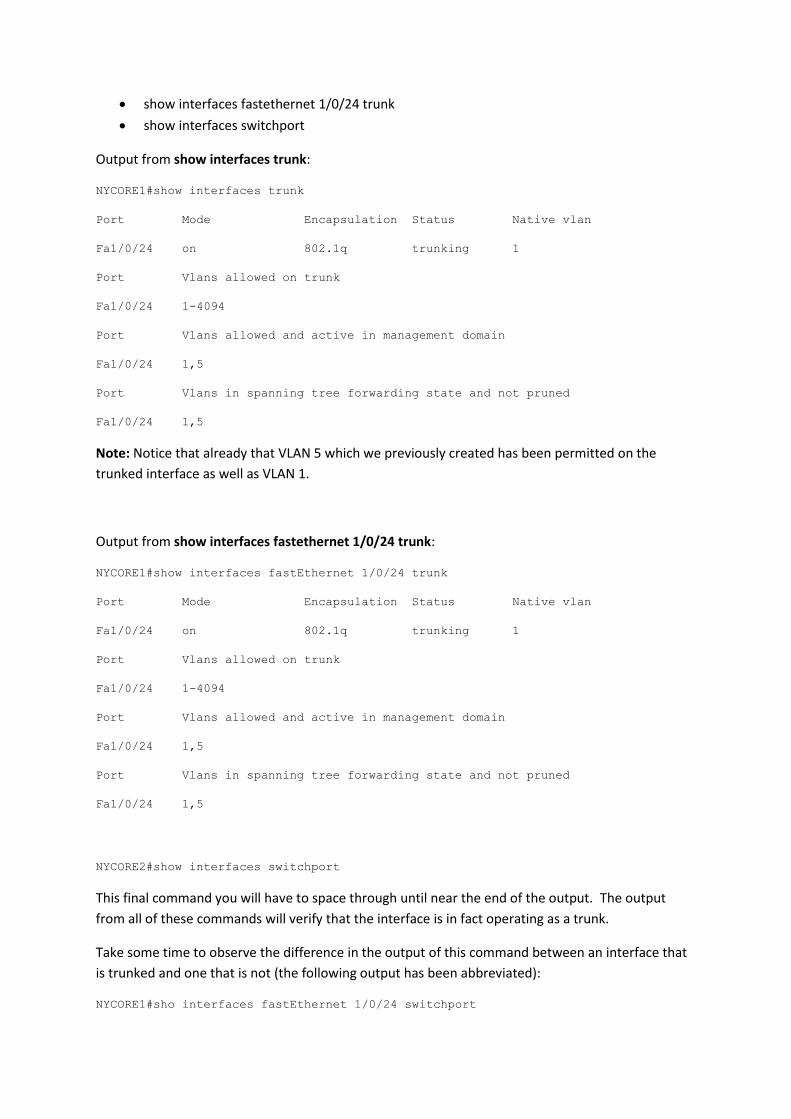
show interfaces fastethernet 1/0/24 trunk
show interfaces switchport
Output from show interfaces trunk:
NYCORE1#show interfaces trunk
Port Mode Encapsulation Status Native vlan
Fa1/0/24 on 802.1q trunking 1
Port Vlans allowed on trunk
Fa1/0/24 1-4094
Port Vlans allowed and active in management domain
Fa1/0/24 1,5
Port Vlans in spanning tree forwarding state and not pruned
Fa1/0/24 1,5
Note: Notice that already that VLAN 5 which we previously created has been permitted on the
trunked interface as well as VLAN 1.
Output from show interfaces fastethernet 1/0/24 trunk:
NYCORE1#show interfaces fastEthernet 1/0/24 trunk
Port Mode Encapsulation Status Native vlan
Fa1/0/24 on 802.1q trunking 1
Port Vlans allowed on trunk
Fa1/0/24 1-4094
Port Vlans allowed and active in management domain
Fa1/0/24 1,5
Port Vlans in spanning tree forwarding state and not pruned
Fa1/0/24 1,5
NYCORE2#show interfaces switchport
This final command you will have to space through until near the end of the output. The output
from all of these commands will verify that the interface is in fact operating as a trunk.
Take some time to observe the difference in the output of this command between an interface that
is trunked and one that is not (the following output has been abbreviated):
NYCORE1#sho interfaces fastEthernet 1/0/24 switchport

Name: Fa1/0/24
Switchport: Enabled
Administrative Mode: trunk
Operational Mode: trunk
Administrative Trunking Encapsulation: dot1q
Operational Trunking Encapsulation: dot1q
Negotiation of Trunking: On
NYCORE2#sho interfaces fastEthernet 1/0/22 switchport
Name: Fa1/0/22
Switchport: Enabled
Administrative Mode: dynamic auto
Operational Mode: static access
Administrative Trunking Encapsulation: negotiate
Operational Trunking Encapsulation: native
Negotiation of Trunking: On
Notice the differences in the first few lines of the output.
Dynamic Trunking Protocol (DTP)
DTP can help create trunk links between compatible devices. In the above example you configured a
static (always on trunk), however DTP is still running on this link, sending advertisements every 30
seconds.
To turn off DTP you would need to issue an additional command on the interface forming the trunk,
switchport nonegotiate.
DTP can run in either auto or desirable mode. Configuring auto negotiation does not form a trunk
link in the event that both ends are configured as auto, one end must be set to request the
formation of a trunk. Desirable on the other hand will form a trunk if the remote end is either
configured as:
A trunk
Set to desirable
Set to auto
In this example, we’ll change NYCORE2 to be set to auto-negotiate, proving that trunk – auto brings
up a trunk link.

Step 1
Use the switchport mode dynamic auto command on interface fastethernet 1/0/24 on NYCORE2 to
modify its negotiation type
NYCORE2(config-if)#switchport mode dynamic auto
NYCORE2(config-if)#exit
NYCORE2(config)#exit
NYCORE2#
Step 2
Verify the interface is still operating as a trunk; use your favourite command from the previous
steps.
NYCORE2#show interfaces trunk
Port Mode Encapsulation Status Native vlan
Fa1/0/24 auto n-802.1q trunking 1
Port Vlans allowed on trunk
Fa1/0/24 1-4094
Port Vlans allowed and active in management domain
Fa1/0/24 1
Port Vlans in spanning tree forwarding state and not pruned
Fa1/0/24 1
NYCORE2#
Notice in the output above that the mode has changed to auto, compare this to the output on
NYCORE1 which shows as on.
In this next example we’ll change both ends of the trunk to be desirable, again proving that the trunk
is formed with this configuration.
Step 1
Use the switchport mode dynamic auto command on interface fastethernet 1/0/24 on NYCORE1
and NYCORE2 to modify its negotiation type.
NYCORE1
NYCORE1#configure terminal
Enter configuration commands, one per line. End with CNTL/Z.
NYCORE1(config)#interface fastethernet 1/0/24

NYCORE1(config-if)#switchport mode dynamic desirable
NYCORE2
NYCORE2#configure terminal
Enter configuration commands, one per line. End with CNTL/Z.
NYCORE2(config)#interface fastethernet 1/0/24
NYCORE2(config-if)#switchport mode dynamic desirable
Step 2
Verify the interface is still operating as a trunk, use your favourite command from the previous
steps.
NYCORE1#show interfaces trunk
Port Mode Encapsulation Status Native vlan
Fa1/0/24 desirable 802.1q trunking 1
Port Vlans allowed on trunk
Fa1/0/24 1-4094
Port Vlans allowed and active in management domain
Fa1/0/24 1,5
Port Vlans in spanning tree forwarding state and not pruned
Fa1/0/24 5
Again, notice in the output that the mode is now set to desirable and the trunk is up.
Controlling VLANs on a trunk Let’s say you wanted to only allow specific VLANs on a trunk link so that either the switch doesn’t
automatically add a VLAN or you want to ensure other network engineers can’t arbitrarily place
interfaces on a switch in to different VLANs. For example if you have an access layer switch which
you don’t want servers to be connected to and you had a number of different server VLANs. You
could block these from operating across the trunk link and hence rendering them unable to
communicate past the access switch (it would be able to communicate to anything else on the
access switch that is also in the same VLAN).
In this scenario (and for other reasons) you can restrict, permit and deny, VLANs from being allowed
on a trunk link. To do this, you use the add or remove keywords when configuring the VLANs.
You can also use the none and all keywords to allow none or all. To see this in action, use the
following steps.

Note: These are locally relevant, of course you can restrict at only one end of a trunk link, or you can
restrict at both. Can you think of a very good reason why you would want to do both?
Step 1
In this example, we’ll only permit VLAN 5 on the trunk. Using NYCORE1, use the following commands
to configure this restriction. First you need to remove all the VLANs and then you need to add in the
VLAN list required.
NYCORE1#configure terminal
Enter configuration commands, one per line. End with CNTL/Z.
NYCORE1(config)#interface fastethernet 1/0/24
NYCORE1(config-if)#switchport trunk allowed vlan none
NYCORE1(config-if)#switchport trunk allowed vlan add 5
Use the show interfaces trunk command to confirm your configuration:
NYCORE1#show interfaces trunk
Port Mode Encapsulation Status Native vlan
Fa1/0/24 desirable 802.1q trunking 1
Port Vlans allowed on trunk
Fa1/0/24 5
Port Vlans allowed and active in management domain
Fa1/0/24 5
Port Vlans in spanning tree forwarding state and not pruned
Fa1/0/24 none
If you compare this output to prior to this configuration change you will notice the Vlans allowed on
trunk has shrunk from 1-4094 to only the VLAN specified in the command.

Summary
In this module you achieved the following activities:
You configured a new VLAN, including naming it.
You saw the differences in the configuration from a VTP transparent switch and a server.
You configured trunking between switches, using a number of different modes.
You restricted access to certain VLANs on your trunk link.