Embed Size (px)
Citation preview

NVR200 Series Network Video Recorders
Quick Guide
Manual Version: P100‐20140125

© 2014, Zhejiang Uniview Technologies Co., Ltd. and its licensors
All Rights Reserved
No part of this manual may be reproduced or transmitted in any form or by any means without prior written consent of Zhejiang Uniview Technologies Co., Ltd.
Notice
The information in this manual is subject to change without notice. Every effort has been made in the preparation of this manual to ensure accuracy of the contents, but all statements, information, and recommendations in this manual do not constitute the warranty of any kind, express or implied.
Environmental Protection
This product has been designed to comply with the requirements on environmental protection. For the proper storage, use and disposal of this product, national laws and regulations must be observed.
Safety and Compliance Information
Conventions Used Symbol
The symbols in this chapter are shown in the following table. They are used to remind the reader of the safety precautions during equipment installation and maintenance.
Safety Symbol
Description
Generic alarm symbol: To suggest a general safety concern.
ESD protection symbol: To suggest electrostatic‐sensitive equipment.
Electric shock symbol: To suggest a danger of high voltage.

Safety Information
WARNING!
Installation and removal of the unit and its accessories must be carriedout by qualified personnel. You must read all of the Safety Instructionssupplied with your equipment before installation and operation.
Warnings:
If the product does not work properly, please contact your dealer or the nearest service center. (We shall not assume any responsibility for problems caused by unauthorized repair or maintenance.)
To reduce the risk of fire or electrical shock, do not expose this product to rain or moisture.
This installation should be made by a qualified service person and should conform to all the local codes.
Please install blackouts equipment into the power supply circuit for convenient supply interruption.
The separate earthing terminal must be permanently connected to earth.
For AC supplied model: The plug‐socket combination must be accessible at all times as it serves as the main disconnecting device.
Before the power cable is installed or removed, the power must be turned off.
To avoid heat accumulation, good ventilation is required for a proper operating environment.
Improper use or replacement of the battery may result in hazard of explosion. Please use the manufacturer recommended battery type.

Caution: Fiber optic ports – optical safety.
Never look at the transmit laser while the power is on. Never lookdirectly at the fiber ports and the fiber cable ends when they arepowered on.
Caution: Use of controls or adjustments to the performance orprocedures other than those specified herein may result in hazardouslaser emissions.
Regulatory Compliance
FCC Part 15
This equipment has been tested and found to comply with the limits for digital device, pursuant to part 15 of the FCC Rules. These limits are designed to provide reasonable protection against harmful interference when the equipment is operated in a commercial environment. This equipment generates, uses, and can radiate radio frequency energy and, if not installed and used in accordance with the instruction manual, may cause harmful interference to radio communications. Operation of this equipment in a residential area is likely to cause harmful interference in which case the user will be required to correct the interference at his own expense. This product complies with Part 15 of the FCC Rules. Operation is subject to the following two conditions: 1. This device may not cause harmful interference. 2. This device must accept any interference received, including
interference that may cause undesired operation.

LVD/EMC Directive
This product complies with the European Low Voltage Directive 2006/95/EC and EMC Directive 2004/108/EC.
WEEE Directive–2002/96/EC
The product this manual refers to is covered by the Waste Electrical & Electronic Equipment (WEEE) Directive and must be disposed of in a responsible manner.
Preface
Audience
This manual is intended for:
Surveillance system planners
Field technical support and servicing engineers
Software installation, configuration, and servicing administrators
Product users
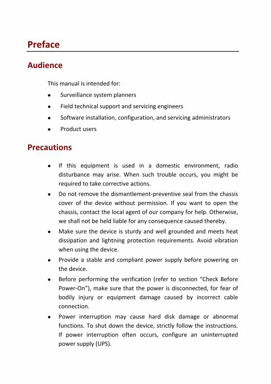
Precautions
If this equipment is used in a domestic environment, radio disturbance may arise. When such trouble occurs, you might be required to take corrective actions.
Do not remove the dismantlement‐preventive seal from the chassis cover of the device without permission. If you want to open the chassis, contact the local agent of our company for help. Otherwise, we shall not be held liable for any consequence caused thereby.
Make sure the device is sturdy and well grounded and meets heat dissipation and lightning protection requirements. Avoid vibration when using the device.
Provide a stable and compliant power supply before powering on the device.
Before performing the verification (refer to section “Check Before Power‐On”), make sure that the power is disconnected, for fear of bodily injury or equipment damage caused by incorrect cable connection.
Power interruption may cause hard disk damage or abnormal functions. To shut down the device, strictly follow the instructions. If power interruption often occurs, configure an uninterrupted power supply (UPS).
i
Contents
1 Overview ............................................................................................... 1
2 Mounting .............................................................................................. 1
Installation Check .......................................................................................... 1
Installing Hard Disks ...................................................................................... 1
Installing the Equipment ............................................................................... 4
3 Appearance ........................................................................................... 5
Front View ..................................................................................................... 5
Indicators ...................................................................................................... 5
Panel buttons ................................................................................................ 6
Rear View ...................................................................................................... 8
Interfaces ...................................................................................................... 9
4 Connecting Cables ............................................................................... 11
Connecting to Alarm Input/Output Device ................................................. 11
Connecting to a Third‐Party Device ............................................................ 12
RS485 Serial Cables ............................................................................. 12
Connecting to a third‐party device via RS485 interface ..................... 13
Connecting using an audio/video cable ...................................................... 13
Connecting to an Audio Intercom Device ................................................... 14
Connecting RS232 Serial And Network Cables ............................................ 15
Connecting to a Powered Device ................................................................ 16
Connecting a GroundCable ......................................................................... 17
5 Switching On/Offthe Device ................................................................. 17
Check Before Power‐On .............................................................................. 17
Turning on the Device ................................................................................. 17
Soft Off ........................................................................................................ 18
Soft Off Using the POWER ON/OFF Button ........................................ 18
Soft Off Through Man‐Machine Interface .......................................... 18

ii
Soft Off Through Web Interface ......................................................... 18
6 Common Configurations ...................................................................... 18
Man‐Machine Interface .............................................................................. 19
About the Interface ............................................................................ 19
Menu Structure .................................................................................. 20
Initial Configuration .................................................................................... 20
Quickly Adding IPC ...................................................................................... 26
Preview ....................................................................................................... 29
Pane Toolbar on the Preview Interface .............................................. 29
Preview Status .................................................................................... 30
Right‐click Context Menu ................................................................... 31
Recording .................................................................................................... 32
Playback ...................................................................................................... 33
Backup ......................................................................................................... 33
Prerequisites ....................................................................................... 33
Procedure ........................................................................................... 33
Web Interface ............................................................................................. 36
7 Specifications ...................................................................................... 37
8 HDD Storage Calculation Chart ............................................................. 38
1
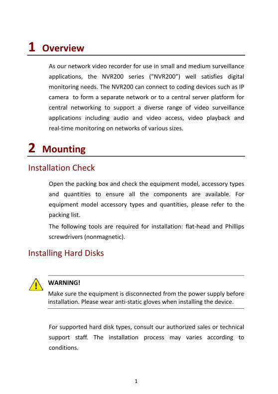
1 Overview
As our network video recorder for use in small and medium surveillance
applications, the NVR200 series ("NVR200”) well satisfies digital
monitoring needs. The NVR200 can connect to coding devices such as IP
camera to form a separate network or to a central server platform for
central networking to support a diverse range of video surveillance
applications including audio and video access, video playback and
real‐time monitoring on networks of various sizes.
2 Mounting
Installation Check
Open the packing box and check the equipment model, accessory types
and quantities to ensure all the components are available. For
equipment model accessory types and quantities, please refer to the
packing list.
The following tools are required for installation: flat‐head and Phillips
screwdrivers (nonmagnetic).
Installing Hard Disks
WARNING!
Make sure the equipment is disconnected from the power supply beforeinstallation. Please wear anti‐static gloves when installing the device.
For supported hard disk types, consult our authorized sales or technical
support staff. The installation process may varies according to
conditions.

2
Install a hard disk as follows:
1. Loosen the seven screws that secure the chassis cover, and remove
the cover.
2. Fix four screws, each half tight, to the hard disk.
3. Connect one end of the data cable to the hard disk.
3
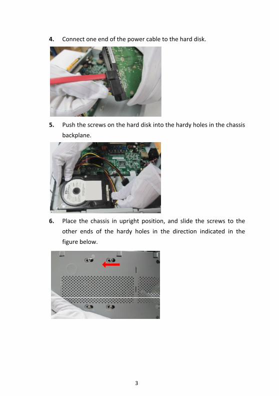
4. Connect one end of the power cable to the hard disk.
5. Push the screws on the hard disk into the hardy holes in the chassis
backplane.
6. Place the chassis in upright position, and slide the screws to the
other ends of the hardy holes in the direction indicated in the
figure below.

4
7. Tighten the screws on the hard disk.
8. Connect the other ends of the data and power cables to the
motherboard.
9. Repeat the above procedure to install another hard disk. It is
recommended that you install two screws on the diagonal.
10. Finally put on and secure the chassis cover with screws. The hard
disk is completely installed.
Installing the Equipment
Leave room of at least 30cm to the front and back and 10cm to the left
and right sides of the equipment for ventilation.
Install the equipment as follows:
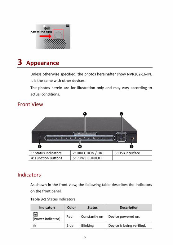
1. Get the stickers from the foot pads delivered with the equipment,
and attach the pads to the bottom of the equipment where
appropriate.
2. Place the equipment on a clean workbench. Now the installation
process is complete.
5
3 Appearance Unless otherwise specified, the photos hereinafter show NVR202‐16‐IN.
It is the same with other devices.
The photos herein are for illustration only and may vary according to
actual conditions.
Front View
1: Status Indicators 2: DIRECTION / OK 3: USB interface 4: Function Buttons 5: POWER ON/OFF
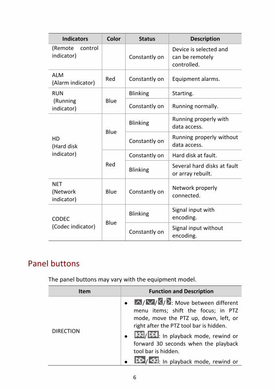
Indicators
As shown in the front view, the following table describes the indicators
on the front panel.
Table 3‐1 Status Indicators
Indicators Color Status Description
(Power indicator)
Red Constantly on Device powered on.
IR Blue Blinking Device is being verified.
6
Indicators Color Status Description
(Remote control indicator) Constantly on
Device is selected and can be remotely controlled.
ALM (Alarm indicator)
Red Constantly on Equipment alarms.
RUN (Running indicator)
Blue Blinking Starting.
Constantly on Running normally.
HD (Hard disk indicator)
Blue
Blinking Running properly with data access.
Constantly onRunning properly without data access.
Red
Constantly on Hard disk at fault.
Blinking Several hard disks at fault or array rebuilt.
NET (Network indicator)
Blue Constantly onNetwork properly connected.
CODEC (Codec indicator)
Blue
Blinking Signal input with encoding.
Constantly onSignal input without encoding.
Panel buttons
The panel buttons may vary with the equipment model.
Item Function and Description
DIRECTION
/ / / : Move between different menu items; shift the focus; in PTZ mode, move the PTZ up, down, left, or right after the PTZ tool bar is hidden.
/ : In playback mode, rewind or forward 30 seconds when the playback tool bar is hidden.
/ : In playback mode, rewind or
7
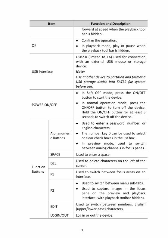
Item Function and Description
forward at speed when the playback tool bar is hidden.
OK Confirm the operation.
In playback mode, play or pause when the playback tool bar is hidden.
USB interface
USB2.0 (limited to 1A) used for connection with an external USB mouse or storage device. Note:
Use another device to partition and format a USB storage device into FAT32 file system before use.
POWER ON/OFF
In Soft OFF mode, press the ON/OFF button to start the device.
In normal operation mode, press the ON/OFF button to turn off the device. Hold the ON/OFF button for at least 3 seconds to switch off the device.
Function Buttons
Alphanumeric Buttons
Used to enter a password, number, or English characters.
The number key 0 can be used to select or clear check boxes in the list box.
In preview mode, used to switch between analog channels in focus panes.
SPACE Used to enter a space.
DEL Used to delete characters on the left of the cursor.
F1 Used to switch between focus areas on an interface.
F2
Used to switch between menu sub‐tabs.
Used to capture images in the focus pane on the preview and playback interface (with playback toolbar hidden).
EDIT Used to switch between numbers, English (upper/lower‐case) characters.
LOGIN/OUT Log in or out the device.
8
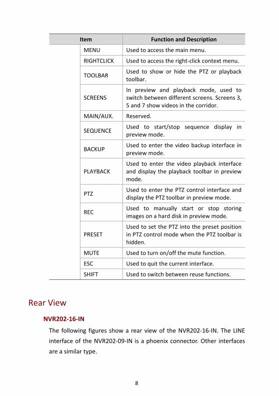
Item Function and Description
MENU Used to access the main menu.
RIGHTCLICK Used to access the right‐click context menu.
TOOLBAR Used to show or hide the PTZ or playback toolbar.
SCREENS In preview and playback mode, used to switch between different screens. Screens 3, 5 and 7 show videos in the corridor.
MAIN/AUX. Reserved.
SEQUENCE Used to start/stop sequence display in preview mode.
BACKUP Used to enter the video backup interface in preview mode.
PLAYBACK Used to enter the video playback interface and display the playback toolbar in preview mode.
PTZ Used to enter the PTZ control interface and display the PTZ toolbar in preview mode.
REC Used to manually start or stop storing images on a hard disk in preview mode.
PRESET Used to set the PTZ into the preset position in PTZ control mode when the PTZ toolbar is hidden.
MUTE Used to turn on/off the mute function.
ESC Used to quit the current interface.
SHIFT Used to switch between reuse functions.
Rear View
NVR202‐16‐IN
The following figures show a rear view of the NVR202‐16‐IN. The LINE
interface of the NVR202‐09‐IN is a phoenix connector. Other interfaces
are a similar type.
9
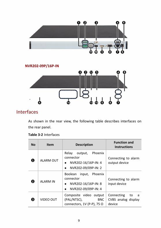
NVR202‐09P/16P‐IN
Interfaces
As shown in the rear view, the following table describes interfaces on
the rear panel.
Table 3‐2 Interfaces
No Item Description Function and Instructions
ALARM OUT
Relay output, Phoenix connector
NVR202‐16/16P‐IN: 4 NVR202‐09/09P‐IN: 2
Connecting to alarm output device
ALARM IN
Boolean input, Phoenix connector
NVR202‐16/16P‐IN: 8 NVR202‐09/09P‐IN: 4
Connecting to alarm input device
VIDEO OUT Composite video output (PAL/NTSC), BNC connectors, 1V (P‐P), 75 Ω
Connecting to a CVBS analog display device
1
2
3
10
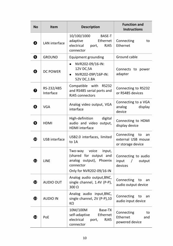
No Item Description Function and Instructions
LAN interface
10/100/1000 BASE‐T adaptive Ethernet electrical port, RJ45 connector
Connecting to Ethernet
GROUND Equipment grounding Ground cable
DC POWER
NVR202‐09/16‐IN: 12V DC,5A
NVR202‐09P/16P‐IN: 52V DC,1.8A
Connects to power adapter
RS‐232/485 Interface
Compatible with RS232 and RS485 serial ports and RJ45 connectors
Connecting to RS232 or RS485 devices
VGA Analog video output, VGA interface
Connecting to a VGA analog display device
HDMI High‐definition digital audio and video output, HDMI interface
Connecting to HDMI display device
USB interfaceUSB2.0 interfaces, limited to 1A
Connecting to an external USB mouse or storage device
LINE
Two‐way voice input, (shared for output and analog output), Phoenix connector Only for NVR202‐09/16‐IN
Connecting to audio input / output devices
AUDIO OUT Analog audio output,BNC, single channel, 1.4V (P‐P), 300 Ω
Connecting to an audio output device
AUDIO IN Analog audio input,BNC, single channel, 2V (P‐P),10 KΩ
Connecting to an audio input device
PoE
10M/100M Base‐TX self‐adaptive Ethernet electrical port, RJ45 connector
Connecting to Ethernet and powered device
4
5
6
7
8
9
10
11
12
13
14
11
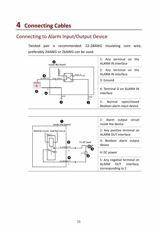
4 Connecting Cables Connecting to Alarm Input/Output Device
Twisted pair is recommended. 22‐28AWG insulating core wire,
preferably 24AWG or 26AWG can be used.
1: Any terminal on the ALARM IN interface
2: Any terminal on the ALARM IN interface
3: Ground
4: Terminal G on ALARM IN interface
5: Normal open/closed Boolean alarm input device
1: Alarm output circuit inside the device
2: Any positive terminal on ALARM OUT interface
3: Boolean alarm output device
4: DC power
5: Any negative terminal on ALARM OUT interface, corresponding to 2
12
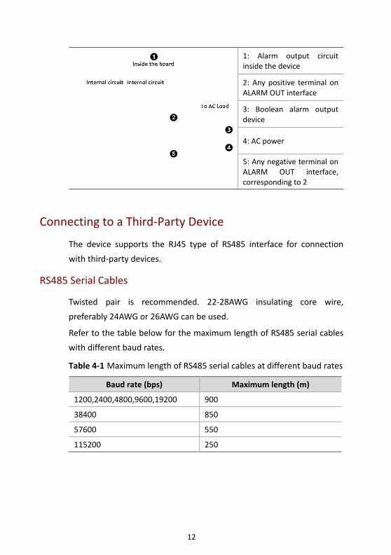
1: Alarm output circuit inside the device
2: Any positive terminal on ALARM OUT interface
3: Boolean alarm output device
4: AC power
5: Any negative terminal on ALARM OUT interface, corresponding to 2
Connecting to a Third‐Party Device
The device supports the RJ45 type of RS485 interface for connection
with third‐party devices.
RS485 Serial Cables
Twisted pair is recommended. 22‐28AWG insulating core wire,
preferably 24AWG or 26AWG can be used.
Refer to the table below for the maximum length of RS485 serial cables
with different baud rates.
Table 4‐1 Maximum length of RS485 serial cables at different baud rates
Baud rate (bps) Maximum length (m)
1200,2400,4800,9600,19200 900
38400 850
57600 550
115200 250
13
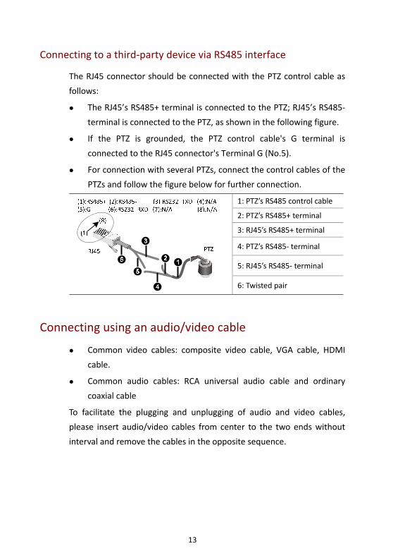
Connecting to a third‐party device via RS485 interface
The RJ45 connector should be connected with the PTZ control cable as
follows:
The RJ45’s RS485+ terminal is connected to the PTZ; RJ45’s RS485‐
terminal is connected to the PTZ, as shown in the following figure.
If the PTZ is grounded, the PTZ control cable's G terminal is
connected to the RJ45 connector's Terminal G (No.5).
For connection with several PTZs, connect the control cables of the
PTZs and follow the figure below for further connection.
1: PTZ’s RS485 control cable
2: PTZ’s RS485+ terminal
3: RJ45’s RS485+ terminal
4: PTZ’s RS485‐ terminal
5: RJ45’s RS485‐ terminal
6: Twisted pair
Connecting using an audio/video cable
Common video cables: composite video cable, VGA cable, HDMI
cable.
Common audio cables: RCA universal audio cable and ordinary
coaxial cable
To facilitate the plugging and unplugging of audio and video cables,
please insert audio/video cables from center to the two ends without
interval and remove the cables in the opposite sequence.
14
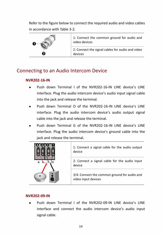
Refer to the figure below to connect the required audio and video cables
in accordance with Table 3‐2.
1: Connect the common ground for audio and video devices
2: Connect the signal cables for audio and video devices
Connecting to an Audio Intercom Device
NVR202‐16‐IN
Push down Terminal I of the NVR202‐16‐IN LINE device’s LINE
interface. Plug the audio intercom device’s audio input signal cable
into the jack and release the terminal.
Push down Terminal O of the NVR202‐16‐IN LINE device’s LINE
interface. Plug the audio intercom device’s audio output signal
cable into the jack and release the terminal.
Push down Terminal G of the NVR202‐16‐IN LINE device’s LINE
interface. Plug the audio intercom device’s ground cable into the
jack and release the terminal.
1: Connect a signal cable for the audio output device
2: Connect a signal cable for the audio input device
3/4: Connect the common ground for audio and video input devices
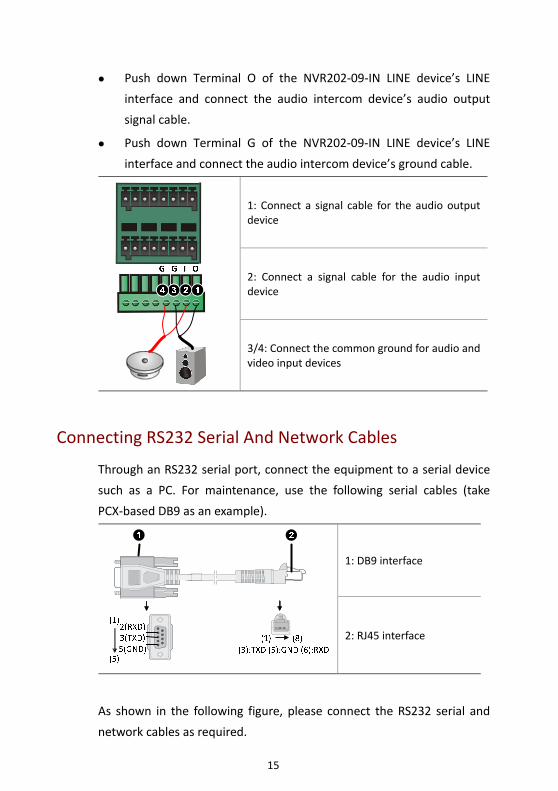
NVR202‐09‐IN
Push down Terminal I of the NVR202‐09‐IN LINE device’s LINE
interface and connect the audio intercom device’s audio input
signal cable.
15
Push down Terminal O of the NVR202‐09‐IN LINE device’s LINE
interface and connect the audio intercom device’s audio output
signal cable.
Push down Terminal G of the NVR202‐09‐IN LINE device’s LINE
interface and connect the audio intercom device’s ground cable.
1: Connect a signal cable for the audio output device
2: Connect a signal cable for the audio input device
3/4: Connect the common ground for audio and video input devices
Connecting RS232 Serial And Network Cables
Through an RS232 serial port, connect the equipment to a serial device
such as a PC. For maintenance, use the following serial cables (take
PCX‐based DB9 as an example).
1: DB9 interface
2: RJ45 interface
As shown in the following figure, please connect the RS232 serial and
network cables as required.
16
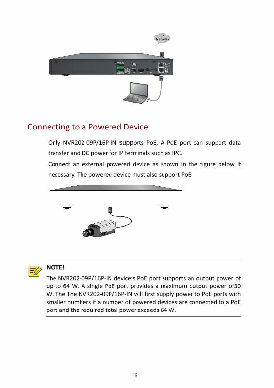
Connecting to a Powered Device
Only NVR202‐09P/16P‐IN supports PoE. A PoE port can support data transfer and DC power for IP terminals such as IPC.
Connect an external powered device as shown in the figure below if
necessary. The powered device must also support PoE.
NOTE!
The NVR202‐09P/16P‐IN device’s PoE port supports an output power ofup to 64 W. A single PoE port provides a maximum output power of30W. The The NVR202‐09P/16P‐IN will first supply power to PoE ports withsmaller numbers if a number of powered devices are connected to a PoEport and the required total power exceeds 64 W.
17
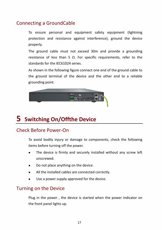
Connecting a GroundCable
To ensure personal and equipment safety equipment (lightning
protection and resistance against interference), ground the device
properly.
The ground cable must not exceed 30m and provide a grounding
resistance of less than 5 Ω. For specific requirements, refer to the
standards for the IEC61024 series.
As shown in the following figure connect one end of the ground cable to
the ground terminal of the device and the other end to a reliable
grounding point.
5 Switching On/Offthe Device Check Before Power‐On
To avoid bodily injury or damage to components, check the following
items before turning off the power.
The device is firmly and securely installed without any screw left
unscrewed.
Do not place anything on the device.
All the installed cables are connected correctly.
Use a power supply approved for the device.
Turning on the Device
Plug in the power , the device is started when the power indicator on
the front panel lights up.
18
In Soft OFF mode, press the POWER ON/OFF button on the front panel
or Remote control to start the device.
Soft Off
Soft off means a device is turned off to terminate the running system
processes, so that the device enters power saving mode.It is
recommended that you disconnect the device from the power supply
when the device is left idle for a long time.
Soft Off Using the POWER ON/OFF Button
Press the POWER ON/OFF button on the front panel or Remote control
and confirm on the man‐machine interface to perform soft off. the
device. Hold the POWER ON/OFF button for at least 3 seconds to switch
off the device.
Soft Off Through Man‐Machine Interface
Choose Menu > Maintenance > Shutdown. Click Shutdown to perform
soft shutdown after confirmation.
Soft Off Through Web Interface
Choose Maintenance > Device Maintenance > Shutdown. Click
Shutdown to perform soft shutdown after confirmation.
WARNING!
In the course of normal operation of the equipment or device is closed, do not disconnect the power while the equipment is running properly orshutting off, so as to not to damage the equipment.
6 Common Configurations
The DVR200 can be operated through man‐machine and Web interfaces.
19
The photos herein are for illustration only and may vary according to
actual conditions.
Man‐Machine Interface
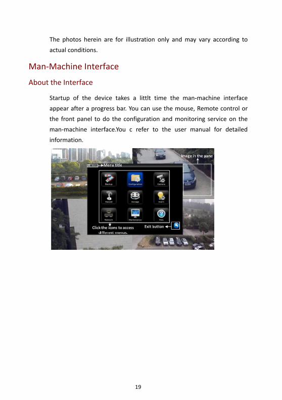
About the Interface
Startup of the device takes a littlt time the man‐machine interface
appear after a progress bar. You can use the mouse, Remote control or
the front panel to do the configuration and monitoring service on the
man‐machine interface.You c refer to the user manual for detailed
information.
20
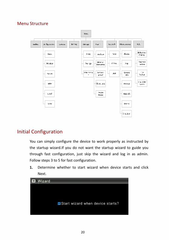
Menu Structure
Initial Configuration
You can simply configure the device to work properly as instructed by
the startup wizard.If you do not want the startup wizard to guide you
through fast configuration, just skip the wizard and log in as admin.
Follow steps 3 to 5 for fast configuration.
1. Determine whether to start wizard when device starts and click
Next.
21
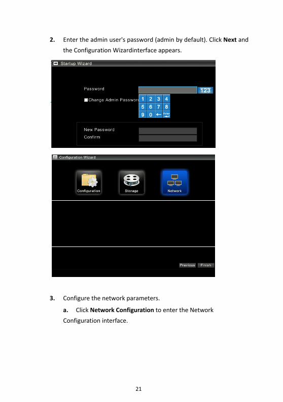
2. Enter the admin user's password (admin by default). Click Next and
the Configuration Wizardinterface appears.
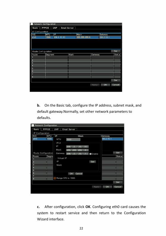
3. Configure the network parameters.
a. Click Network Configuration to enter the Network
Configuration interface.
22
b. On the Basic tab, configure the IP address, subnet mask, and
default gateway.Normally, set other network parameters to
defaults.
c. After configuration, click OK. Configuring eth0 card causes the
system to restart service and then return to the Configuration
Wizard interface.
23
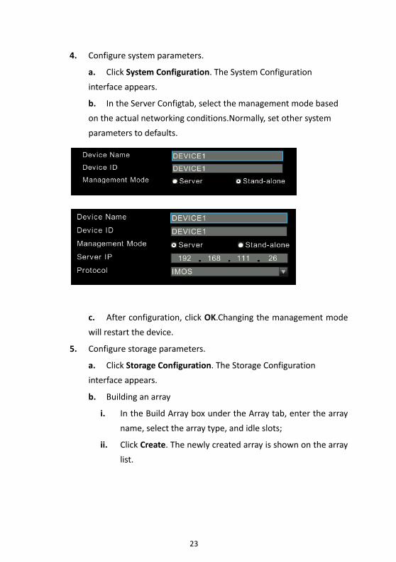
4. Configure system parameters.
a. Click System Configuration. The System Configuration
interface appears.
b. In the Server Configtab, select the management mode based
on the actual networking conditions.Normally, set other system
parameters to defaults.
c. After configuration, click OK.Changing the management mode
will restart the device.
5. Configure storage parameters.
a. Click Storage Configuration. The Storage Configuration
interface appears.
b. Building an array
i. In the Build Array box under the Array tab, enter the array
name, select the array type, and idle slots;
ii. Click Create. The newly created array is shown on the array
list.
24
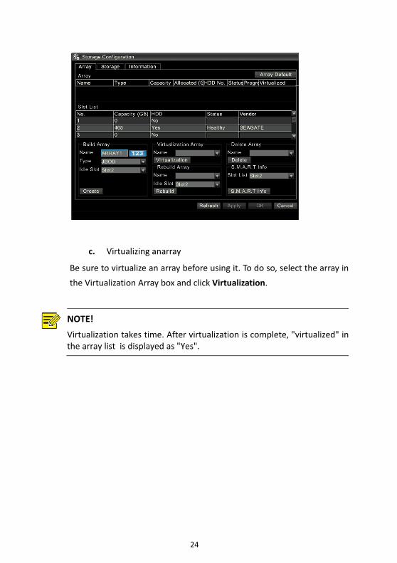
c. Virtualizing anarray
Be sure to virtualize an array before using it. To do so, select the array in
the Virtualization Array box and click Virtualization.
NOTE!
Virtualization takes time. After virtualization is complete, "virtualized" inthe array list is displayed as "Yes".
25
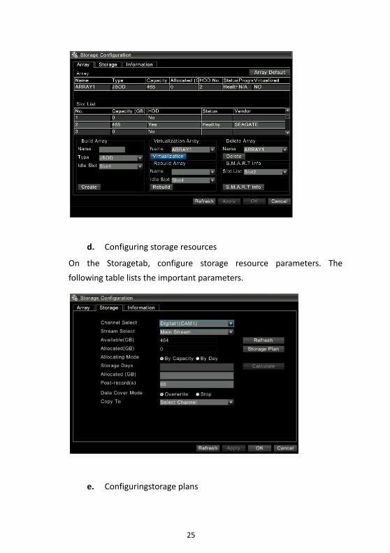
d. Configuring storage resources
On the Storagetab, configure storage resource parameters. The
following table lists the important parameters.
e. Configuringstorage plans
26
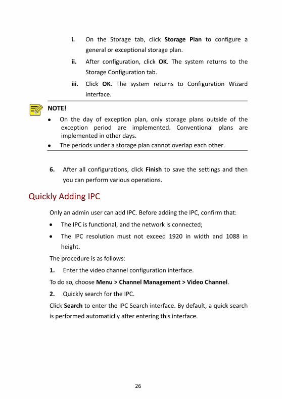
i. On the Storage tab, click Storage Plan to configure a
general or exceptional storage plan.
ii. After configuration, click OK. The system returns to the
Storage Configuration tab.
iii. Click OK. The system returns to Configuration Wizard
interface.
NOTE!
On the day of exception plan, only storage plans outside of theexception period are implemented. Conventional plans areimplemented in other days.
The periods under a storage plan cannot overlap each other.
6. After all configurations, click Finish to save the settings and then
you can perform various operations.
Quickly Adding IPC
Only an admin user can add IPC. Before adding the IPC, confirm that:
• The IPC is functional, and the network is connected;
• The IPC resolution must not exceed 1920 in width and 1088 in
height.
The procedure is as follows:
1. Enter the video channel configuration interface.
To do so, choose Menu > Channel Management > Video Channel.
2. Quickly search for the IPC.
Click Search to enter the IPC Search interface. By default, a quick search
is performed automaticlly after entering this interface.

27
3. Add our company's IPC.
• Add single IPC: Select one of our IPCs you want to add. The IPC
parameters are displayed below the list.(You can modify related
parameters, Important parameters are described in the following
table.) Click Add to add the IPC.
• Add IPCs in batches: Select a number of our IPCs you want to add.
Click Batch Add and the system will add IPCs in batches according to
default parameters.
28
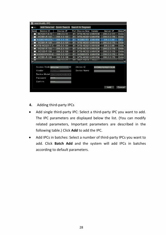
4. Adding third‐party IPCs
• Add single third‐party IPC: Select a third‐party IPC you want to add.
The IPC parameters are displayed below the list. (You can modify
related parameters, Important parameters are described in the
following table.) Click Add to add the IPC.
• Add IPCs in batches: Select a number of third‐party IPCs you want to
add. Click Batch Add and the system will add IPCs in batches
according to default parameters.
29
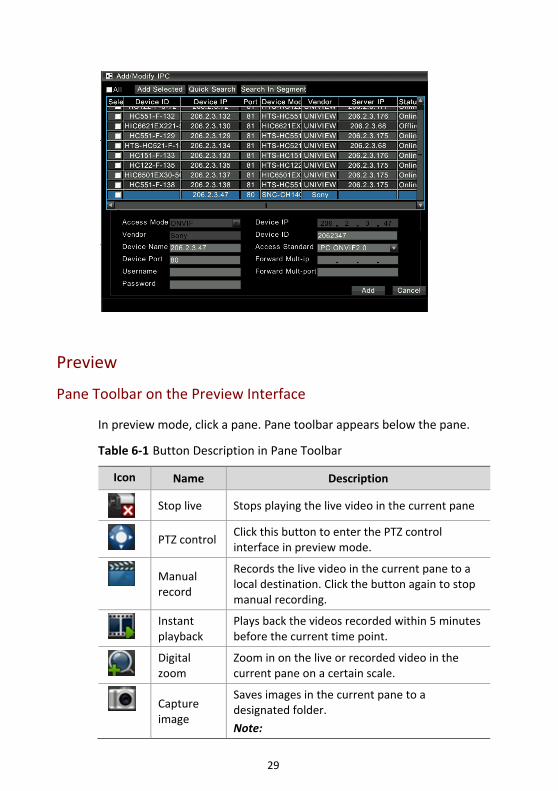
Preview
Pane Toolbar on the Preview Interface
In preview mode, click a pane. Pane toolbar appears below the pane.
Table 6‐1 Button Description in Pane Toolbar
Icon Name Description
Stop live Stops playing the live video in the current pane
PTZ controlClick this button to enter the PTZ control interface in preview mode.
Manual record
Records the live video in the current pane to a local destination. Click the button again to stop manual recording.
Instant playback
Plays back the videos recorded within 5 minutes before the current time point.
Digital zoom
Zoom in on the live or recorded video in the current pane on a certain scale.
Capture image
Saves images in the current pane to a designated folder.
Note:
30
Icon Name Description
Images captured are stored by date in the root directory of your USB drive (a folder is automatically created and named "snap_ date").For example, images captured on March 24, 2013 are stored in a folder named "snap_2013‐03‐24".
Before capturing images, ensure that you have inserted a USB drive into the device.
Images captured in preview mode are named as follows: user name (camera name) current time.jpg.
Exit the tool bar
Exit the toolbar for the current pane.
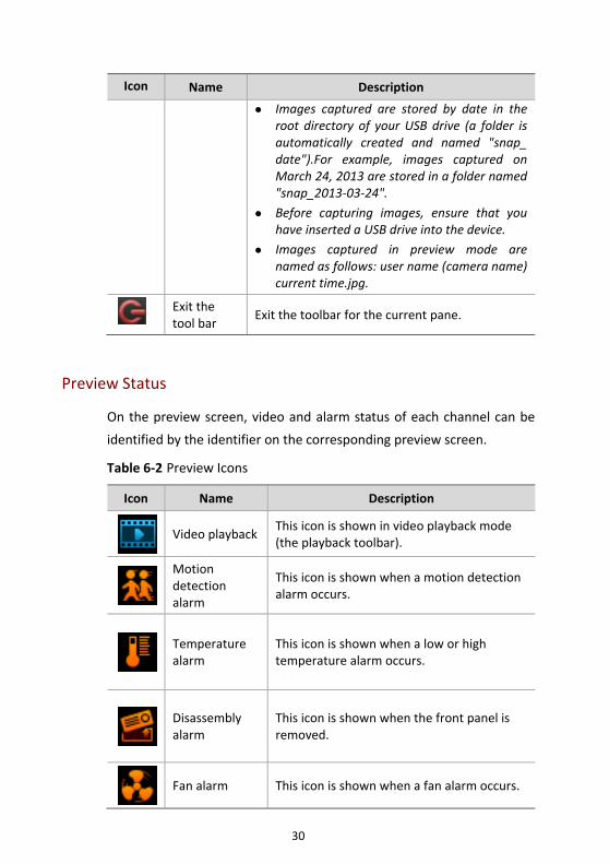
Preview Status
On the preview screen, video and alarm status of each channel can be
identified by the identifier on the corresponding preview screen.
Table 6‐2 Preview Icons
Icon Name Description
Video playbackThis icon is shown in video playback mode (the playback toolbar).
Motion detection alarm
This icon is shown when a motion detection alarm occurs.
Temperature alarm
This icon is shown when a low or high temperature alarm occurs.
Disassembly alarm
This icon is shown when the front panel is removed.
Fan alarm This icon is shown when a fan alarm occurs.
31
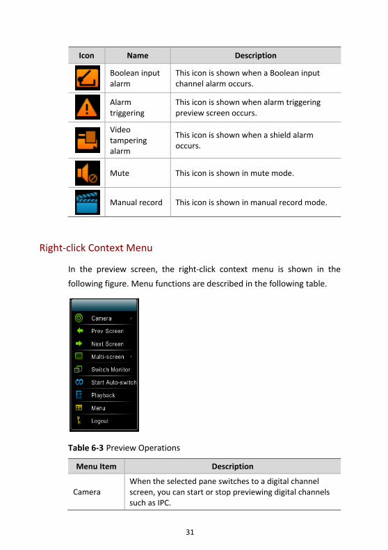
Icon Name Description
Boolean input alarm
This icon is shown when a Boolean input channel alarm occurs.
Alarm triggering
This icon is shown when alarm triggering preview screen occurs.
Video tampering alarm
This icon is shown when a shield alarm occurs.
Mute This icon is shown in mute mode.
Manual record This icon is shown in manual record mode.
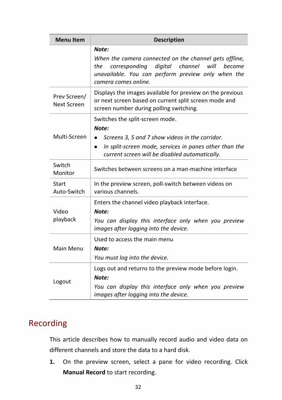
Right‐click Context Menu
In the preview screen, the right‐click context menu is shown in the
following figure. Menu functions are described in the following table.
Table 6‐3 Preview Operations
Menu Item Description
Camera When the selected pane switches to a digital channel screen, you can start or stop previewing digital channels such as IPC.
32
Menu Item Description
Note:
When the camera connected on the channel gets offline, the corresponding digital channel will become unavailable. You can perform preview only when the camera comes online.
Prev Screen/Next Screen
Displays the images available for preview on the previous or next screen based on current split screen mode and screen number during polling switching.
Multi‐Screen
Switches the split‐screen mode.
Note: Screens 3, 5 and 7 show videos in the corridor.
In split‐screen mode, services in panes other than the current screen will be disabled automatically.
Switch Monitor
Switches between screens on a man‐machine interface
Start Auto‐Switch
In the preview screen, poll‐switch between videos on various channels.
Video playback
Enters the channel video playback interface.
Note:
You can display this interface only when you preview images after logging into the device.
Main Menu
Used to access the main menu
Note:
You must log into the device.
Logout
Logs out and returns to the preview mode before login.
Note:
You can display this interface only when you preview images after logging into the device.
Recording
This article describes how to manually record audio and video data on
different channels and store the data to a hard disk.
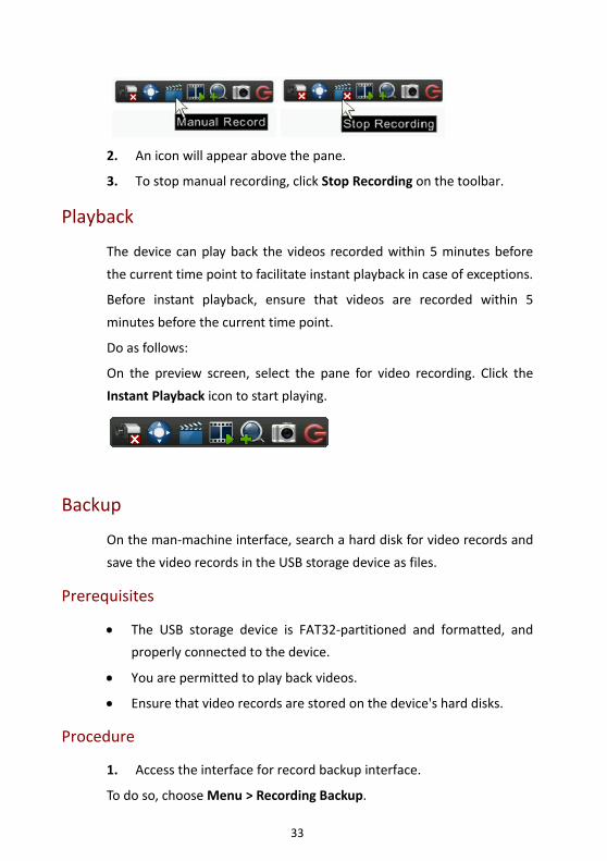
1. On the preview screen, select a pane for video recording. Click
Manual Record to start recording.
33
2. An icon will appear above the pane.
3. To stop manual recording, click Stop Recording on the toolbar.
Playback
The device can play back the videos recorded within 5 minutes before
the current time point to facilitate instant playback in case of exceptions.
Before instant playback, ensure that videos are recorded within 5
minutes before the current time point.
Do as follows:
On the preview screen, select the pane for video recording. Click the
Instant Playback icon to start playing.
Backup
On the man‐machine interface, search a hard disk for video records and
save the video records in the USB storage device as files.
Prerequisites
• The USB storage device is FAT32‐partitioned and formatted, and
properly connected to the device.
• You are permitted to play back videos.
• Ensure that video records are stored on the device's hard disks.
Procedure
1. Access the interface for record backup interface.
To do so, choose Menu > Recording Backup.
34
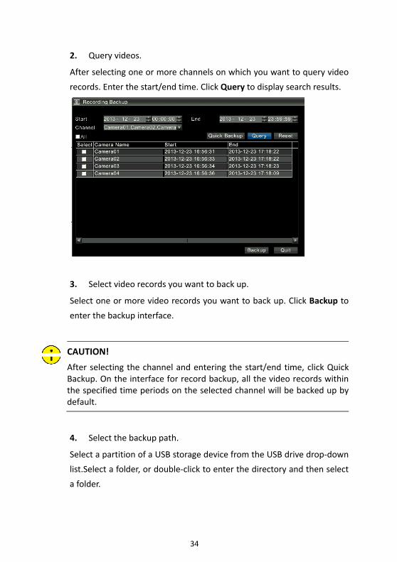
2. Query videos.
After selecting one or more channels on which you want to query video
records. Enter the start/end time. Click Query to display search results.
3. Select video records you want to back up.
Select one or more video records you want to back up. Click Backup to
enter the backup interface.
CAUTION!
After selecting the channel and entering the start/end time, click QuickBackup. On the interface for record backup, all the video records withinthe specified time periods on the selected channel will be backed up bydefault.
4. Select the backup path.
Select a partition of a USB storage device from the USB drive drop‐down
list.Select a folder, or double‐click to enter the directory and then select
a folder.

35
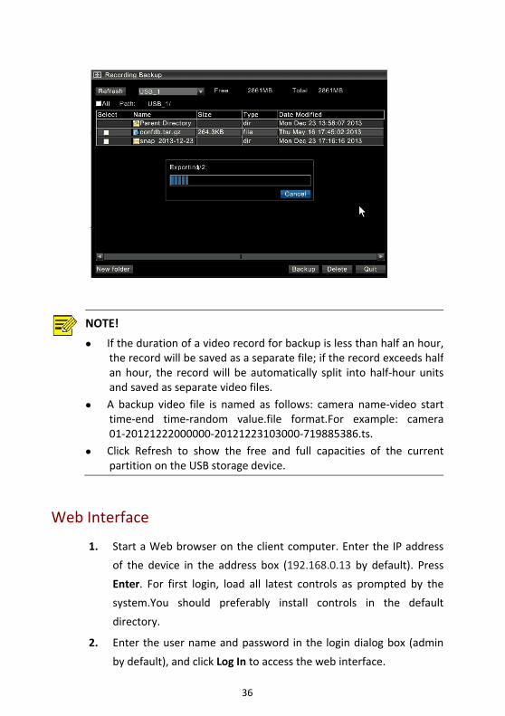
5. Backing up a video
Click Backup to start video backup.
CAUTION!
During the backup process, the progress bar will show "backing up X/Y:"x indicates the video records currently being backed up; y represents thetotal number of video records you want to back up.During the backupprocess, click Cancel on the progress bar to stop video backup.
36
NOTE!
If the duration of a video record for backup is less than half an hour,the record will be saved as a separate file; if the record exceeds halfan hour, the record will be automatically split into half‐hour unitsand saved as separate video files.
A backup video file is named as follows: camera name‐video starttime‐end time‐random value.file format.For example: camera01‐20121222000000‐20121223103000‐719885386.ts.
Click Refresh to show the free and full capacities of the currentpartition on the USB storage device.
Web Interface
1. Start a Web browser on the client computer. Enter the IP address
of the device in the address box (192.168.0.13 by default). Press
Enter. For first login, load all latest controls as prompted by the
system.You should preferably install controls in the default
directory.
2. Enter the user name and password in the login dialog box (admin
by default), and click Log In to access the web interface.
37
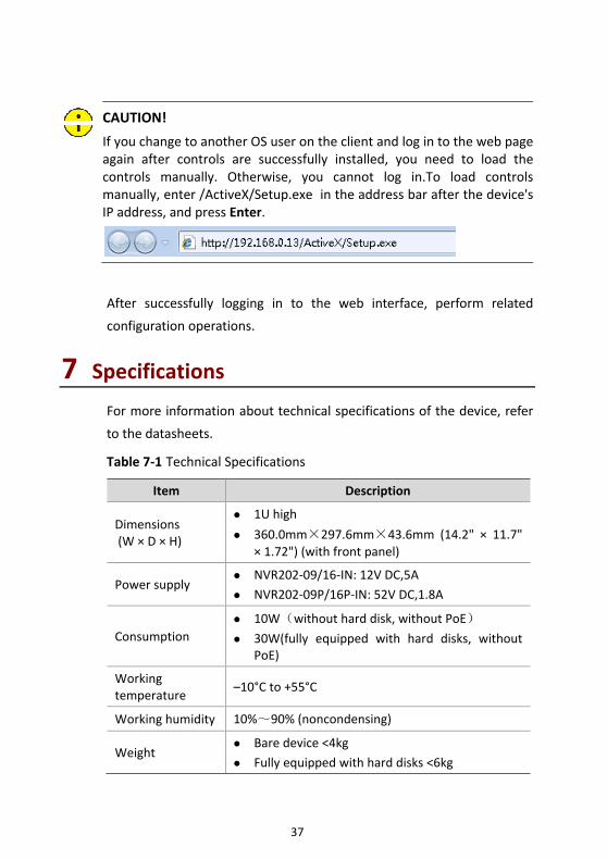
CAUTION!
If you change to another OS user on the client and log in to the web pageagain after controls are successfully installed, you need to load thecontrols manually. Otherwise, you cannot log in.To load controlsmanually, enter /ActiveX/Setup.exe in the address bar after the device'sIP address, and press Enter.
After successfully logging in to the web interface, perform related
configuration operations.
7 Specifications For more information about technical specifications of the device, refer
to the datasheets.
Table 7‐1 Technical Specifications
Item Description
Dimensions (W × D × H)
1U high
360.0mm×297.6mm×43.6mm (14.2" × 11.7" × 1.72") (with front panel)
Power supply NVR202‐09/16‐IN: 12V DC,5A
NVR202‐09P/16P‐IN: 52V DC,1.8A
Consumption 10W(without hard disk, without PoE)
30W(fully equipped with hard disks, without PoE)
Working temperature
–10°C to +55°C
Working humidity 10%~90% (noncondensing)
Weight Bare device <4kg
Fully equipped with hard disks <6kg
38
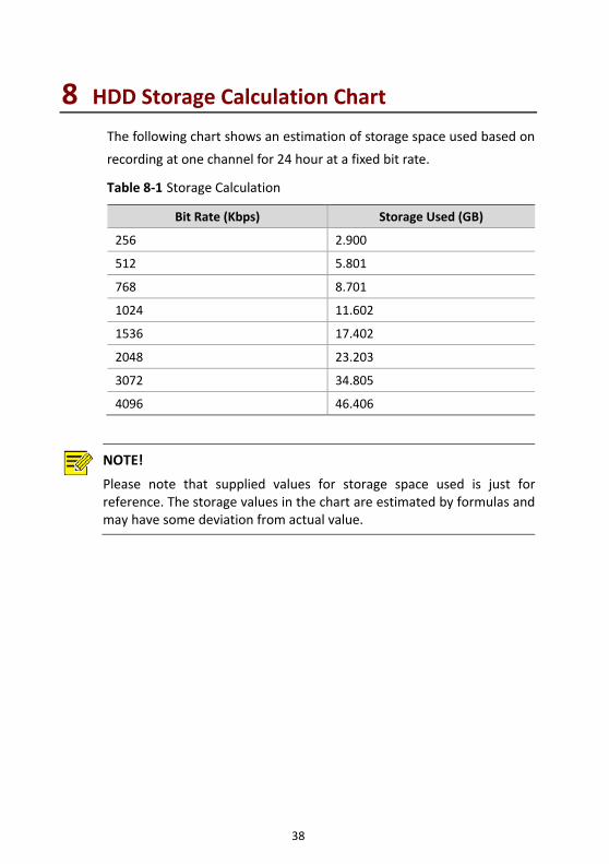
8 HDD Storage Calculation Chart The following chart shows an estimation of storage space used based on
recording at one channel for 24 hour at a fixed bit rate.
Table 8‐1 Storage Calculation
Bit Rate (Kbps) Storage Used (GB)
256 2.900
512 5.801
768 8.701
1024 11.602
1536 17.402
2048 23.203
3072 34.805
4096 46.406
NOTE!
Please note that supplied values for storage space used is just forreference. The storage values in the chart are estimated by formulas andmay have some deviation from actual value.

BOM: 3101C035