Embed Size (px)
Citation preview

Research ArticleNumerical Study of Damage Modes and Damage Assessment ofCFST Columns under Blast Loading
Junhao Zhang1 Shiyong Jiang1 Bin Chen2 Chunhai Li3 and Hao Qin3
1Chongqing Key Laboratory of Geomechanics amp Geoenvironmental Protection Logistical Engineering UniversityChongqing 401311 China2Institute of Engineering Mechanics China Earthquake Administration Harbin 150080 China3Beijing Canbao Institute of Architectural Design Beijing 100850 China
Correspondence should be addressed to Shiyong Jiang jiangshy1163com
Received 2 September 2015 Revised 22 November 2015 Accepted 24 November 2015
Academic Editor Sakdirat Kaewunruen
Copyright copy 2016 Junhao Zhang et al This is an open access article distributed under the Creative Commons Attribution Licensewhich permits unrestricted use distribution and reproduction in any medium provided the original work is properly cited
Columns of frame structures are the key load-bearing components and the exterior columns are susceptible to attack in terroristblasts When subjected to blast loads the columns would suffer a loss of bearing capacity to a certain extent due to the damageimparted which may induce the collapse of them and even cause the progressive collapse of the whole structure In this paperthe high-fidelity physics-based finite element program LS-DYNA was utilized to investigate the dynamic behavior and damagecharacteristics of the widely used concrete-filled steel tube (CFST) columns subjected to blast loads The established numericalmodel was calibrated with test data in open literatures Possible damagemodes of CFST columns under blast loading were analyzedand the damage criterion based on the residual axial load capacity of the columns was adopted to assess the damage degree Aparametric study was conducted to investigate the effects of critical parameters such as blast conditions and column details on thedamage degree of CFST columns Based on the numerical simulation data an empirical equation was proposed to estimate thevariation of columns damage degree with the various parameters
1 Introduction
Concrete-filled steel tube (CFST) columns have been widelyused in engineering structures such as high-rise buildingsarch bridges and factories as they have advantages of highstrength and excellent ductility due to a confinement effectand a changed buckling mode [1 2] With the increase ofterrorist bombings in recent years blast resistance of thestructures has become a consideration in their design process[3] When subjected to blast loads columns may suffer a lossof bearing capacity to a certain extent due to the damageimparted which may induce the collapse of the columns andeven cause the progressive collapse of the whole structureIn addition both concrete and steel of which CFST columnsare composed may respond to blast loads at very high strainrates in the order of 1ndash100 sminus1 or even higher thus makingthe dynamic analysis of the CFST columns different fromthat under static loads and earthquake actions Therefore it
is of realistic significance to study the dynamic behavior anddamage characteristics of CFST columns under blast loading
Fujikura et al experimentally investigated the dynamicresponses of CFST bridge pier column specimens under blastloading According to the magnitude of the support rotationthe damage states of the column specimens were categorizedinto three types that is the plastic deformation onset offracture and postfracture The authors also compared themaximum response of the specimens obtained from thesimplified method based on the equivalent single-degree-of-freedom (SDOF) theory with the test data [4 5] Li et alstudied the dynamic behavior of CFST columns through aseries of field blast experiments They analyzed the effects ofexplosive mass standoff distance axial load ratio concretestrength grade and steel ratio on the displacement and strainresponses of CFST columns which showed global-mode con-trolled responses in the tests [6] Remennikov and Uy carriedout field tests on the CFST specimens and demonstrated the
Hindawi Publishing CorporationShock and VibrationVolume 2016 Article ID 3972791 12 pageshttpdxdoiorg10115520163972791
2 Shock and Vibration
The steel frame
The test pit The pneumatic jack
(a) The steel frame that holds the specimen in place
Steel tubeInfill concrete
LVDTRoller supportGround
Pneumatic jack
Explosive28mm200mm
200
mm
1500
mm
380mm380mm
(b) The test configuration
Figure 1 Test setup (Zhang et al [9])
effects of scaled standoff distance on the mode of responseand failure of the specimens under near-field blast loadingIt was found that CFST members may suffer severe localizeddamage due to the highly localized blast impulse when theexplosive was located quite close to the test members Theauthors also developed a simplified engineering-level modelfor prediction of the mid-span deflection history of theCFST member [7] Ngo et al utilized the coupled Arbi-trary Lagrange Euler (ALE) blast wave-structure interactionalgorithms and numerically investigated the failure patternsdeformation histories and energy absorption characteristicsof CFST members subjected to near-field blast loadingTwo distinct phases of deformation were identified in thestudy of which the local deformation that initially occurredrather than the flexural global deformation that followeddominates the energy absorption history of the columnspecimen [8] Zhang et al carried out blast tests and finiteelement simulations on the axially compressed CFST columnmembers Results indicated that CFST columns showedgood resistance against flexural loads under blast loadingThe energies absorbed by local deformation and flexuraldeformation of the column during the blast loading were alsoinvestigated and it was found that themajority of the energieswere absorbed by global deformation when the mode ofresponse was mainly flexural [9] The authors also investi-gated the dynamic responses and damage characteristics ofthe concrete-filled columns with double-skin tubes to blastloads and the critical parameters that affect the displacementtime histories of the columns were analyzed [10]
The review of these literatures indicates that the mode ofresponse and damage criterion are key issues in understand-ing the dynamic behavior anddamage characteristics ofCFSTcolumns subjected to blast loads as some damage criterionsare only applicable to certain damage mode of the columnsand different conclusionsmay be drawn under varied damagemodes as stated previously The objective of this paper isto study the damage modes and damage assessment ofCFST columns under blast loading The numerical modelis established using the finite element program LS-DYNAand calibrated with correlated experimental studies by otherresearchers Possible damagemodes of the columns subjected
to blast loads are analyzed and the criterion suitable to assessthe degree of the columns damage is adopted accordinglyParameters that may affect the damage degree of the columnsare analyzed in the study they are blast condition columndimension steel ratio and axial load ratio which are thenincorporated into a proposed equation capable of estimatingthe damage degree of CFST columns based on the numericalresults
2 Numerical Model Calibration
The high-fidelity physics-based finite element program LS-DYNA was used in the paper To calibrate the employednumerical models for simulating the dynamic responses ofCFST columns to blast loads one of the blast tests on CFSTcolumns conducted by Zhang et al [9] was simulated anda comparison was made between the test and numericalsimulation results Figure 1 shows the sketch of test setupof column number S4 The dimensions of the column are2500mm (height) times 200mm (width) times 200mm (depth)with the tube thickness of 28mm The yield stress ultimatestress Youngrsquos modulus and elongation of the steel tubeare 3582MPa 4374MPa 2026GPa and 213 respectivelyThe average cubic compressive strength of the infill concreteis 474MPa which is 379MPa if converted to cylindricalcompressive strength During the test the specimen wasfirstly placed on a steel frame which was then placed into thetest pit The specimen was simply supported by four rollers(two at each ends) thus the effective span of it was 2300mmA steel plate was placed between the roller and the column toavoid stress concentrationThe initial axial load (514 kN) wasapplied to the ends of the column through a pneumatic jackprior to blast loading and then 50 kg of emulsion explosive(equivalent to 35 kg of TNT)was ignited in the air at a standoffdistance (center of explosive to the mid of column frontsurface) of 1500mm to generate the blast environment
21 Numerical Model
211 Material Model Considering the large strain and highstrain rate problems involved in analyzing the responses of
Shock and Vibration 3
Stre
ss
0
Yield stress
E
Et
120573 = 0 kinematic hardening
120573 = 1 isotropic hardening
l0 and l are undeformed anddeformed lengths of uniaxialtension specimen
ln(ll0)
Figure 2 Plastic kinematic model for steel modeling
steel tube under blast loading the plastic kinematic modelwhich takes into account the strain hardening and strain rateeffects is adopted for steel simulation The dynamic yieldstress of it is expressed as follows [11]
120590119910
= (1205900
+ 120573119864119875
120576119875
eff) [1 + (120576
119862
)
1119875
] (1)
where 120590119910
is the dynamic yield stress 1205900
is the initial yieldstress 120573 is the hardening parameter (for 120573 equal to 0 and1 resp kinematic and isotropic hardenings are obtained asshown in Figure 2)119864
119875
is the plastic hardeningmodulus119864119875
=
119864119864119905
(119864 minus 119864119905
) 119864 is Youngrsquos modulus and 119864119905
is the tangentmodulus 120576119875eff is the effective plastic strain 120576 is the strain rateand119862 and119875 areCowper-Symonds strain rate parameters [12]Material parameters of the steel tube in the study are listed inTable 1
The infill concrete subjected to blast loading may expe-rience large strains high strain rates and high pressuresBesides the collapse of air void as well as the dilationcaused by shearing cracks plays an important role in thedamage evolution of concrete Thus the Johnson-Holmquist-Cook (JHC) concrete model is used to simulate the concreteand the equivalent stress of it is expressed as a function ofpressure strain rate and damage as follows [13]
120590lowast
= [119860 (1 minus 119863) + 119861119875lowast119873
] (1 + 119862 ln 120576lowast) le 119878MAX (2)
where 120590lowast = 1205901198911015840119888
denotes the normalized equivalent stress(where 120590 and 1198911015840
119888
are the actual equivalent stress and quasi-static uniaxial compressive strength resp) 119860 is the normal-ized cohesive strength 119863 is the accumulated damage 119861 isthe normalized pressure hardening coefficient 119875lowast = 1198751198911015840
119888
is the dimensionless form of pressure 119875 119873 is the pressurehardening exponent 119862 is strain rate coefficient 120576lowast = 120576 120576
0
isthe dimensionless form of strain rate 120576 (where 120576
0
= 10 sminus1 isthe reference strain rate) and 119878MAX is the normalized maxi-mum strength as shown in Figure 3
Nor
mal
ized
equi
vale
nt st
ress120590lowast
Normalized pressure Plowast
120576lowast = 10
120576lowast gt 10
Tlowast(1 minus D)
D = 0 (undamaged)
D = 1 (fractured)
SMAX
Figure 3 JHC model for concrete modeling
The accumulated damage is expressed as
119863 = sum
Δ120576119875
+ Δ120583119875
1198631
(119875lowast
+ 119879lowast
)119863
2
(3)
where Δ120576119875
and Δ120583119875
are the equivalent plastic strain andplastic volumetric strain respectively119863
1
and1198632
are damageconstants and 119879lowast = 1198791198911015840
119888
is the dimensionless tensile hydro-static pressure
The relation between pressure and volumetric strain isdefined as
119875 =
119870119890
120583 0 le 119875 lt 119875119862
119875119862
+ 119870119862
(120583 minus 120583119862
) 119875119862
le 119875 lt 119875119871
1198701
120583 + 1198702
1205832
+ 1198703
1205833
119875 ge 119875119871
(4)
where 119870119890
is the elastic bulk modulus 119870119890
= 119875119862
120583119862
and 119875119862
and 120583119862
are the pressure and volumetric strain when crushingoccurs in concrete120583 is the volumetric strain120583 = (120583minus120583
119871
)(1+
120583119871
) is the corrected volumetric strain and 119875119871
and 120583119871
are thelocking pressure and volumetric strain at the beginning of thefully compacted stage (119875 ge 119875
119871
) 1198701
1198702
and 1198703
are materialconstants of concrete
The reliability of this concrete model in predicting theresponses of concrete structures to blast loads has beendemonstrated by many researchers [14 15] Material parame-ters of the infill concrete in the simulation are listed inTable 2
212 Finite Element Model and Erosion Algorithm TheBelytschko-Tsay shell element is used in the study to modelthe steel tube and the infill concrete is modeled with single-point integration solid elements A mesh size of 25mm isselected for the steel tube and infill concrete through a numer-ical convergence study It is found that further refinementof element size has little effect on the numerical results butincreases the calculation time enormously A perfect bondbetween steel tube and infill concrete is assumed in the
4 Shock and Vibration
Table 1 Material parameters of the steel tube
Parameter Mass density1205881
(kgm3) Poissonrsquos ratio 120592 1205900
(MPa) 119864 (GPa) 119864119905
(MPa) 120573 119862 P Failure strain(FS)
Value 7850 03 358 203 414 0 404 5 02
Table 2 Material parameters of the infill concrete
Parameter Mass density1205882
(kgm3) 119860 119861 119862 119873 1198911015840
119888
(MPa) 119878MAX
Value 2440 079 160 0007 061 379 70
Parameter Shear modulus119866 (GPa)
Maximumtensile pressure119879 (MPa)
Thresholdstrain rateEPS0 (sminus1)
Plastic strainbefore fracture
EFMIN
Crushingpressure119875119862
(MPa)
Crushingvolumetricstrain 119880
119862
Lockingpressure119875119871
(MPa)Value 1486 40 10 001 16 0001 800
ParameterLocking
volumetricstrain 119880
119871
Damageconstant1198631
Damageconstant1198632
Pressureconstant1198701
(GPa)
Pressureconstant1198702
(GPa)
Pressureconstant1198703
(GPa)Value 01 004 10 85 minus171 208
numerical study since no researches have reported a notice-able debond between the twomaterials in blast tests In orderto simulate the physical fracture shear failure and crushingof the concrete under blast loading the erosion algorithm isused to account for concrete failure Considering the strainrate effect on the concrete strength the erosion criterionbased on the principle strain is often used [16] A numberof simulations are carried out with different erosion criteriaand it is found that using principle tensile strain of 001 as theerosion criterion which is also used by Ngo et al [8] leads toreliable predictions of the responses of CFST columns
213 Sequence of Loads Application and Blast LoadModellingIn order to simulate the real stress state of CFST columns thelinearly increasing axial quasi-static loads up to the serviceaxial load level are applied to the top of the column prior toblast loading through the implicit solver To avoid too muchoscillation of the column the time duration for increasingthe loads from zero to full service level is 150ms Then thecomputational algorithm switches from implicit to explicitand the blast loads are applied over the front surface of thecolumn with the axial loads unchanged
Blast loads are generated using the ConWep air blastmodel [17] that is Load Blast Enhanced in LS-DYNA[18] Compared to other techniques that is the ArbitraryLagrangian Eulerian (ALE) methodology this model is morecomputationally efficient to simulate blast loads with a highlevel of accuracy While similar to the model Load Blast italso includes enhancements for treating reflected waves Theloading face of the column is predefined before the generationof blast loads and the time history of blast loads actingon each segment is calculated through ConWep formula asfollows
119875 (119905) = 119875119903
(119905) cos2120579 + 119875119894
(119905) (1 + cos2120579 minus 2 cos 120579) (5)
where 119875(119905) is the reflected overpressure on the definedload segment at moment 119905 119875
119903
(119905) and 119875119894
(119905) are the normal
0 25 50 75 100 125 150 175 200
Time (ms)
0
minus10
minus20
minus30
minus40
minus50
minus60
minus70
Late
ral d
ispla
cem
ent (
mm
)
Test by Zhang et al [9]Residual displacement in the testNumerical simulation
Figure 4 Comparison of the displacement data from test and thatof numerical simulation
reflected overpressure and incident overpressure at moment119905 respectively and 120579 is the angle of incidence of the blast wave
22 Model Calibration and Discussion Numerical simula-tions of the blast test were carried out and the dynamicresponse and damage mode of column S4 were obtainedSince the recording of LVDT1 at the center of column S4 wasmissing in the test the value of LVDT2 (see Figure 1(b)) at380mm from the center of the column was used to calibratethe numerical model Comparison of the calculated displace-ment time history with test results is shown in Figure 4It is found that the peak displacement of numerical results(509mm) is smaller than that in the test (60mm) while thenumerical residual displacement (354mm) is slightly largerthan the test value (34mm) Several factors as follows may
Shock and Vibration 5
(a) Test result (Zhang et al [9])
Fringe levels
6346eminus02
5289eminus02
4231e
minus02
3173eminus02
2115eminus02
1058e
minus02
0000e
+00
(b) Numerical result
Figure 5 Comparison of the column damage mode in the test andthat from numerical simulation
account for such discrepancies (1) the difference between theactual support condition which is not rigid enough and thoseadopted in the simulation (2) ignorance of the potential lossof axial loads and reduction of flexural resistance consideringthe detachment of the column ends from the loading devicein the test and (3) the limitations of material models indepicting the real-time nonlinear behaviors of steel andconcrete during test Although discrepancies exist betweenthe simulation and test values the largest error with respectto the maximum displacements is within 152 Figure 5shows the comparison of the damage mode of the columnin the test and that from the numerical simulation presentedin effective plastic strain contour and good agreement isobserved in between These results demonstrate that thecalibrated numericalmodel leads to reasonable predictions ofthe dynamic responses and damage modes of CFST columnsto blast loads and can be used for the subsequent study
3 Damage Modes of CFST Column underBlast Loading
31 Column Configuration The above calibrated numericalmodel is utilized herein to simulate dynamic behavior andpossible damagemodes of CFST column under blast loadingThe column is designed based on the specifications providedby Chinese Standard CECS 159 2004 [19] As shown inFigure 6 the dimensions of the column are ℎ (height) times119908 (width)times119889 (depth) = 3700mm times 600mm times 600mm withthe tube thickness of 18mm Parameters of the steel tube andthe infill concrete used in the simulation are the same asthose in Section 2 In order to simulate the real life boundaryconditions for CFST columns a column head and a footingare considered in the numericalmodelThe outer vertical faceof the footing and head are constrained against horizontalmotions and the bottom face of the footing is constrainedagainst vertical motions [20] Horizontal distance from thecharge center to the column front surface that is the standoffdistance is denoted as 119883 And the vertical distance fromthe charge center to the ground that is the height of burstis denoted as 119867
119861
The initial dead weight imposed on the
Table 3 Possible damage modes of the CFST column
119872 (kg) 119867119861
(m) 119885 (mkg13) Damage mode
50 0le021 Localized
022ndash024 Shearge026 Flexural
250 0le025 Localized
030ndash048 Shearge052 Flexural
50 185 le016 Localizedge018 Flexural
column is 35 percent of axial load capacity of the undamagedcolumn which represents the axial load level of a typicalground floor column in a high-rise building
As the blast load parameters are related to both explosivemass and standoff distance the scaled standoff distance isintroduced to consider their combined effects and is definedas [21]
119885 =
119883
11987213
(6)
where 119885 is the scaled standoff distance and 119872 is theequivalent mass of TNT
32 Possible Damage Modes Three damage modes of theCFST column under blast loading have been observedthrough a number of simulations they are flexural damageshear damage and localized damage Table 3 presents damagemodes of the column according to different blast conditionsIt is found that in general explosivewith a small scaled stand-off distance favors a localized damage whilst shear damageand localized damage occur when the explosive is relativelyfar from the columnThis is because the blast loads are highlyintensive when the scaled standoff distance is small and forvery local blast loads acting on the column failure of the infillconcrete and steel tube starts before any considerable overallresponse can occur and the column surfers a localized dam-age However with the increase of scaled standoff distanceblast loads tend to be well-distributed over the surface of thecolumn which is inclined to response globally and undergoshear damage and flexural damage Also the damagemode isaffected by the explosive mass height of burst Typical resultsof these damagemodes are shown with effective plastic straincontours in Figures 7ndash9
Figure 7 shows the flexural damage mode of the CFSTcolumn induced by the detonation of 50 kg of TNT at thescaled standoff distance of 018mkg13 with the height ofburst of 185m In this configuration when the blast loadsacted on the column the mid-part of it responded imme-diately with the increment of lateral deformation Then theareas near the supports of the column began to deform androtate As the global flexural deformation of the columnevolved plastic hinges developed in the mid-part and nearthe supports of the columnwhere the bendingmoments werelarge
6 Shock and Vibration
First-floor column
Second-floor column
Explosive
Second-floor beam
h
HB
X
(a) Explosion scenario
1 1
Section 1-1
Steel tube
Infill concrete
Axial load
Head
Footing
First-floor column
h d t
w
(b) Column details
Figure 6 Sketch of the numerical analysis model
Figure 8 shows the shear damage mode of the columnresulted from 250 kg of TNT detonating on the ground atthe scaled standoff distance of 033mkg13 Due to the largeshear force and the development of shear deformation nearthe supports the infill concrete was sheared off accompaniedwith the rupture of the steel tube around the cross section ofthe column Finally the column failed in brittle shear beforeany ductile flexural hinge developed
As discussed above flexural damage and shear damageof the column are due to the deformation and internal forceof the whole member induced by the blast loads On thecontrary localized damage of the CFST column is dominatedby the deformation and failure of the concrete infill and steeltube in the vicinity of the explosion whilst other parts of thecolumn remain almost elastic and the global deformation ofthe column is small
Figure 9 shows the localized damage mode of the CFSTcolumn caused by the detonation of 50 kg of TNT on theground with the scaled standoff distance of 018mkg13When the impulsive shock front of high intensity metthe column surface the stress waves were generated andpropagated from the tube front surface towards the concreteinfill and the lateral and back surfaces of the tube Then theconcrete close to the explosion was cracked and crushed andthe front side of the tube which lost the internal support ofthe concrete fill was squashed with the bulging of its lateraland back sides As the localized deformation of the columnevolved rupture and local buckling failure of the steel tubetook place yet the global lateral deformation of the columnhad almost not developed at this moment
It should bementioned that these damagemodes are onlytypical ones Sometimes there exists a combination of thesedamage modes
4 Damage Assessment of CFST Columnsunder Blast Loading
41 Damage Criterion As discussed previously the CFSTcolumn subjected to blast loads may undergo flexural dam-age shear damage and localized damage thus the damagecriterion for the column should be chosen carefully andthe appropriate one is expected to be applicable to all thepossible damage modes of the column In this paper thedamage criterion based on the residual axial load capacityis adopted for CFST columns due to the following reasons(1) the structure column is primarily designed to carry theaxial load and the axial load capacity of it reflects bothits global properties and material characteristics (2) thecommonly used deformation-based damage criterions thatis the support rotation lateral deflection and ductility maynot be appropriate for the evaluation of localized damage ofthe column and (3) the residual axial load capacity of thecolumns is an explicit metric of the damage imparted and italso provides information in assessing the collapse possibilityof a blast damaged column
The damage index adopted herein is based on the indexfrom Shi et al [20] and is expressed as
119863119888
= 1 minus
119875residual119875max
(7)
where 119863119888
is the damage degree of CFST columns 119875residual isthe residual axial load capacity of the column after blast loadsand 119875max is the maximum axial load capacity of the columnprior to blast loading Values of 119863
119888
vary between 0 (ieno loss of capacity) and 10 (ie complete loss of capacity)Note that in the paper by Shi et al [20] the maximumaxial load capacity of an undamaged column is calculated
Shock and Vibration 7
Fringe levels
3793eminus02
3161e
minus02
2529eminus02
1897eminus02
1264eminus02
6322eminus03
0000e
+00
(a) CFST column
Fringe levels
3793eminus02
3161e
minus02
2529eminus02
1897eminus02
1264eminus02
6322eminus03
0000e
+00
(b) Infill concrete
Figure 7 Flexural damage mode of CFST column under blast loading
Fringe levels
2000e
minus01
1667eminus01
1333eminus01
1000e
minus01
6667eminus02
3333eminus02
0000e
+00
(a) CFST column
Fringe levels
2392e
minus02
1993eminus02
1594eminus02
1196eminus02
7972e
minus03
3986eminus03
0000e
+00
(b) Infill concrete
Figure 8 Shear damage mode of CFST column under blast loading
8 Shock and Vibration
Fringe levels
2000e
minus01
1667eminus01
1333eminus01
1000e
minus01
6667eminus02
3333eminus02
0000e
+00
(a) CFST column
Fringe levels
2597eminus02
2165eminus02
1732e
minus02
1299eminus02
8658e
minus03
4329eminus03
0000e
+00
(b) Infill concrete
Figure 9 Localized damage mode of CFST column under blast loading
with the provided equation from the standard design codewhich however may lead to the values of119863
119888
below 0 in somecases Therefore both 119875residual and 119875max are determined fromnumerical simulation in this study Here 119875residual119875max is alsotermed as the residual capacity index (RCI) used byWu et al[22] andCrawford et al [23] to assess the damage level of steelreinforced concrete (SRC) columns and reinforced concrete(RC) columns subjected to blast loads
It is noted that if the ratio of the service axial load tomaximum axial load capacity of the column is denoted as 119899then a column whose119863
119888
is greater than (1 minus 119899) is consideredas failed or collapsed since its residual axial load capacity isnot sufficient for the service axial load
42 Steps for Damage Assessment of CFST Columns
Step 1 (derivation of 119875max) During this step the linearlyincreasing axial load is applied on the column head until thecolumn collapses then 119875max is determined as the maximumaxial load that the column can withstand
Step 2 (derivation of 119875residual) Three substeps as follows arerequired to obtain 119875residual (1) before blast loading a linearlyincreasing axial load up to the service axial load is imposedon the column (2) blast loads are applied over the front faceof the column with the service axial load being constant andcalculation is stopped when the damaged column approachesstatic equilibrium (3) a linearly increasing axial load isimposed on the top of the damaged column until it collapses
then 119875residual is determined as the peak of the axial load thatthe damaged column can bear
Step 3 (determination of 119863119888
) Substitute the values of 119875maxand 119875residual into (7) to obtain119863119888
43 Parameters Studied In this section effects of severalkey parameters on the damage degree of CFST columnsare analyzed These parameters include the scaled standoffdistance height of burst explosive mass column depthcolumn width column steel ratio and axial load ratio aslisted in Table 4 in which a contrast case is generated bychanging one of the parameters considered in the benchmarkcase while keeping other parameters unchanged Note thatin each case varied scaled standoff distances are consideredso that the effects aforementioned parameters on the damagedegree of columns within different blast loading regimes canbe assessed
431 Effect of Scaled Standoff Distance 119885 The numericalsimulation results show that 119863
119888
of CFST columns decreaseswith the increasing scaled standoff distance regardless ofother parameters This is because column damage is affectedby the peak overpressure and impulse of the blast wave[21] and both of them drop with the rising scaled standoffdistance which results in a small degree of column damage
432 Effect of Height of Burst119867119861
It is difficult to characterizethe effect of 119867
119861
on the damage degree of the column On
Shock and Vibration 9
Table 4 Parameters used in the numerical parametric study
Parameters 119885 (mkg13) 119867119861
(m) 119872 (kg) 119889 (m) 119908 (m) Steel ratio 120572lowast Axial load ratio 119899Benchmark case 018ndash050 0 50 06 06 013 035Contrast cases 015ndash090 185 250 500 09 12 09 12 016 019 050 065lowast
120572 = 119860119904
119860119888
119860119904
and 119860119888
are the cross-sectional areas of steel tube and infill concrete respectively
07
06
05
04
03
02
01
00
HB = 0mHB = 185m
015 020 025 030 035 040 045 050
Scaled standoff distance Z (mkg13)
[M = 50kg] [w = 06m] [d = 06m] [120572 = 013] [n = 035]
Dam
age d
egre
eDc
Figure 10 Effects of height of burst on the damage degree
one hand when 119867119861
nears zero the initial blast wave isimmediately reflected and reinforced by the ground On theother the mid-height of the column is expected to surfer themost severe damage due to lack of transverse support Conse-quently as shown in Figure 10 surface burst results in severerdamage to the column than that caused by explosion atcolumnmid-height (119867
119861
= 185m) especially when the stand-off distance is small The effects of119867
119861
on the damage degreeof the column are insignificant at large scaled distancesbecause both the overpressure and impulse on the columnare relatively small in these cases
433 Effect of Explosive Mass119872 Figure 11 shows the effectsof explosive mass on the damage degree of the columnInspections of the figure show that 119863
119888
rises with 119872 for thesame scaled standoff distance indicating that CFST columnis impulse-sensitive since explosive with larger mass hasrelatively more impulse for the column
434 Effects of Column Width 119908 and Depth 119889 Effects ofcolumn depth and width on 119863
119888
are shown in Figure 12Comparedwith the reference column (119908 = 06m 119889 = 06m)columns with larger width and depth tend to have lowerdamage degrees because expanding columnwidth and depthproduces a larger cross section for attenuation of the stresswaves density and contributes to enhancement of the shearresistance as well as flexural strength of the columnHoweverit is found that columns with the same cross section area butdifferent width and depth have varied damage degrees and
07
06
05
04
03
02
01
0002 03 04 05 06 07 08 09 10
Scaled standoff distance Z (mkg13)
M = 50kgM = 250kgM = 500kg
[HB = 0m] [w = 06m] [d = 06m] [120572 = 013] [n = 035 ]
Dam
age d
egre
eDc
Figure 11 Effects of explosive mass on the damage degree
07
06
05
04
03
02
01
00015 020 025 030 035 040 045
Scaled standoff distance Z (mkg13)
w = 06m d = 06mw = 09m d = 06mw = 12m d = 06m
w = 06m d = 09mw = 06m d = 12m
[HB = 0m] [M = 50kg] [120572 = 013] [n = 035 ]
Dam
age d
egre
eDc
Figure 12 Effects of width and depth on the damage degree
that compared with increasing the column width incrementof the column depth is more effective in reducing the columndamage degree This is because enlarging the column widthsimultaneously results in a rise of blast loads acting on thecolumnwhich balances out the enhancement of columnblastresistance to some extent
10 Shock and Vibration
07
06
05
04
03
02
01
00015 020 025 030 035 040 045
Scaled standoff distance Z (mkg13)
120572 = 013
120572 = 016
120572 = 019
[HB = 0m] [M = 50kg] [w = 06m] [d = 06m] [n = 035 ]
Dam
age d
egre
eDc
Figure 13 Effects of steel ratio on the damage degree
07
06
05
04
03
02
01
00020 025 030 035 040 045 050
Scaled standoff distance Z (mkg13)
n = 035
n = 050
n = 065
[HB = 0m] [M = 50kg] [w = 06m] [d = 06m] [120572 = 013]
Dam
age d
egre
eDc
Figure 14 Effects of axial load ratio on the damage degree
435 Effect of Column Steel Ratio 120572 As shown in Figure 13119863119888
drops with the rising steel ratio This is expected becauseincreasing 120572means a larger steel area and better confinementof infill concrete which will enhance the shear and bendingstrength of the column as well as its resistance to localizeddamage
436 Effect of Column Axial Load Ratio 119899 Effects of axialload ratio on 119863
119888
are shown in Figure 14 Inspection of thefigure reveals that axial load ratio has dual influences on col-umn damage When the scaled standoff is small the columnwith a larger axial load ratio has lower damage degree Thisis because the column under small scaled standoff is likelyto suffer localized damage and shear damage and a higher
axial load will restrain the cracking and crushing of concretewhich enhances the resistance of the column to localizeddamage and shear damage In contrast at a large scaledstandoff distance the column with larger axial load ratio hashigher damage degree The reason is that with the increaseof the scaled standoff distance the column tends to sufferflexural damage which is related to its moment capacity andductility The larger the moment capacity and ductility arethe lower the damage degree is For the CFST column studiedin this section the axial load ratio at the maximum momentcapacity is 022 which is derived by the methods from Choiet al [1] According to the axial load-bending moment (P-M)interactions the moment capacity of the CFST column willdecrease when 119899 rises from 035 to 060 Moreover a risingaxial load will reduce the ductility of the CFST column
44 Empirical Equations for Determining the Damage Degreeof CFST Columns The parametric study revealed the signif-icance of parameters affecting the damage degree of CFSTcolumns Through the multivariable regression analysis anempirical equation is proposed in terms of various parame-ters to predict the damage degree and is expressed as follows
119863119888
= [minus1505 ln(11987250
) + 1650 (
119908
06
) minus 3242 (
119889
06
)
minus 131625120572 + 15349119899 + 25011]
sdot 119890[minus648ln(11987250)+533(11990806)minus1091(11988906)minus373minus1230120572+1292119899+2681]119885
(8)
The comparisons of the proposed equation with the ana-lytical results are shown in Figures 15(a)ndash15(f) The scattersdenote the analytical results and the solid lines represent theproposed equation Observation of these figures shows thatthe proposed curves are close to the analytical results formostcases The effects of height of burst on the damage degree ofCFST columns are not reflected by (8) due to the lack of blastdata in the lower height of the column which are limited inthe ConWep model and will be supplemented in the furtherstudies
5 Conclusions
This paper presents a 3D numerical model to investigate thedamage modes and damage assessment of CFST columnsBased on the numerical analysis results the following con-clusions can be drawn
CFST columns under blast loading may undergo theglobal flexural damage and shear damage as well as localizeddamage Flexural damage and shear damage of the columnare mainly attributed to the deformation and internal force ofthe whole member whilst the localized damage is dominatedby the failure of infill concrete and steel tube in the vicinity ofthe explosion
The damage criterion based on the residual axial loadcapacity is adopted for assessing the degree of CFST columnsdamage to blast loadsThrough parametric studies it is foundthat the damage degree of CFST columns decays nearlyexponentially with the increasing scaled standoff distance
Shock and Vibration 11
07
06
05
04
03
02
01
00
[M = 50kg] [w = 06m] [d = 06m] [120572 = 013] [n = 035]
055020 025 030 035 040 045 050
Scaled standoff distance Z (mkg13)
Analytical resultsProposed equation
Dam
age d
egre
eDc
(a)
07
06
05
04
03
02
01
00095090085050 055 060 065 070 075 080
Scaled standoff distance Z (mkg13)
Analytical resultsProposed equation
[M = 500kg] [w = 06m] [d = 06m] [120572 = 013] [n = 035 ]
Dam
age d
egre
eDc
(b)
07
06
05
04
03
02
01
00
Analytical resultsProposed equation
015 020 025 030 035 040 045
Scaled standoff distance Z (mkg13)
[M = 50kg] [w = 12m] [d = 06m] [120572 = 013] [n = 035]
Dam
age d
egre
eDc
(c)
020
015
010
005
000
Analytical resultsProposed equation
015 020 025 030 035 040 045
Scaled standoff distance Z (mkg13)
[M = 50kg] [w = 06m] [d = 12m] [120572 = 013] [n = 035]D
amag
e deg
reeD
c
(d)
06
05
04
03
02
01
00
Analytical resultsProposed equation
015 020 025 030 035 040 045
Scaled standoff distance Z (mkg13)
[M = 50kg] [w = 06m] [d = 06m] [120572 = 019] [n = 035]
Dam
age d
egre
eDc
(e)
020
025
030
035
015
010
005
000055020 025 030 035 040 045 050
Scaled standoff distance Z (mkg13)
Analytical resultsProposed equation
[M = 50kg] [w = 06m] [d = 06m] [120572 = 013] [n = 065]
Dam
age d
egre
eDc
(f)
Figure 15 Comparison of analytical results with the proposed curves
12 Shock and Vibration
For the same scaled standoff distance surface burst results inseverer damage to the column than that caused by explosionat columnmid-height and the damage degree increases withthe rising explosive mass and decreases with column depthand width and steel ratio Increasing the axial load enhancesthe resistance of the column against localized damage andshear damage while the effects of axial load on flexuraldamage depend on the axial load-bending moment (P-M)interactions of the column
An equation is derived by fitting the results of parametricstudies to estimate the damage degree of CFST columnsTypical examples confirm that the proposed equation wellrepresents the variation of the column damage degree How-ever future experiments can be conducted for investigatingthe effects of other parameters on the damage degree of CFSTcolumns
Conflict of Interests
The authors declare that there is no conflict of interestsregarding the publication of this paper
Acknowledgments
The research described in this paper was financially sup-ported by Achievement Transfer Program of Institutionsof Higher Education in Chongqing under Grant noKJZH14220
References
[1] Y-H Choi D A Foutch and J M LaFave ldquoNew approachto AISC P-M interaction curve for square concrete filled tube(CFT) beamndashcolumnsrdquo Engineering Structures vol 28 no 11pp 1586ndash1598 2006
[2] Y-H Choi K S Kim and S-M Choi ldquoSimplified P-M interac-tion curve for square steel tube filled with high-strength con-creterdquoThin-Walled Structures vol 46 no 5 pp 506ndash515 2008
[3] T KrauthammerModern Protective Structures TaylorampFrancisGroup New York NY USA 2008
[4] S C Fujikura M Bruneau and D Lopez-Garcia ldquoExperimen-tal investigation of blast performance of seismically resistantconcrete-filled steel tube bridge piersrdquo Tech Rep MCEER-07-0005 University at Buffalo Buffalo NY USA 2007
[5] S Fujikura M Bruneau and D Lopez-Garcia ldquoExperimentalinvestigation of multihazard resistant bridge piers having con-crete-filled steel tube under blast loadingrdquo Journal of BridgeEngineering vol 13 no 6 pp 586ndash594 2008
[6] G Li H Qu T Yang Y Lu and S Chen ldquoExperimental studyof concrete-filled steel tubular columns under blast loadingrdquoJianzhu Jiegou Xuebao vol 34 no 12 pp 69ndash76 2013 (Chinese)
[7] A M Remennikov and B Uy ldquoExplosive testing andmodellingof square tubular steel columns for near-field detonationsrdquo Jour-nal of Constructional Steel Research vol 101 pp 290ndash303 2014
[8] T Ngo D Mohotti A Remennikov and B Uy ldquoNumericalsimulations of response of tubular steel beams to close-rangeexplosionsrdquo Journal of Constructional Steel Research vol 105 pp151ndash163 2015
[9] F R Zhang C Q Wu H W Wang and Y Zhou ldquoNumericalsimulation of concrete filled steel tube columns against BLASTloadsrdquoThin-Walled Structures vol 92 pp 82ndash92 2015
[10] F Zhang C Wu X Zhao Z Li A Heidarpour and H WangldquoNumerical modeling of concrete-filled double-skin steelsquare tubular columns under blast loadingrdquo Journal of Per-formance of Constructed Facilities vol 29 no 5 Article IDB4015002 2015
[11] Livermore Software Technology Corporation LS-DYNA Theo-retical Manual Livermore Software Technology CorporationLivermore Calif USA 1998
[12] G R Cowper and P S Symonds ldquoStrain-hardening and strain-rate effects in the impact loading of cantilever beamsrdquo TechRep AD144762 Office of Naval Research Arlington Va USA1958
[13] T J Holmquist G R Johnson and W H Cook ldquoA computa-tional constitutive model for concrete subjected to large strainshigh strain rates and high pressuresrdquo in Proceedings of the 14thInternational Symposium on Ballistics Quebec City CanadaSeptember 1993
[14] Q Fang and J Zhang ldquoThree-dimensional modelling of steelfiber reinforced concrete material under intense dynamic load-ingrdquo Construction and Building Materials vol 44 pp 118ndash1322013
[15] Y Li F Lin X L Gu and X Q Lu ldquoNumerical researchof a super-large cooling tower subjected to accidental loadsrdquoNuclear Engineering and Design vol 269 pp 184ndash192 2014
[16] J Li and H Hao ldquoNumerical study of concrete spall damage toblast loadsrdquo International Journal of Impact Engineering vol 68pp 41ndash55 2014
[17] G Randers-Pehrson and K A Bannister ldquoAirblast loadingmodel for DYNA2D and DYNA3Drdquo Tech Rep ARL-TR-1310Army Research Laboratory Adelphi Md USA 1997
[18] Livermore Software Technology Corporation LS-DYNA Key-word Userrsquos Manual (Version 971 R610) Livermore SoftwareTechnology Corporation Livermore Calif USA 2012
[19] CECS ldquoTechnical specification for structures with concrete-filled rectangular steel tube membersrdquo CECS 1592004 ChinaAssociation for Engineering Construction StandardizationBeijing China 2004 (Chinese)
[20] Y Shi H Hao and Z-X Li ldquoNumerical derivation of pressure-impulse diagrams for prediction of RC column damage to blastloadsrdquo International Journal of Impact Engineering vol 35 no11 pp 1213ndash1227 2008
[21] P D Smith and J G Hetherington Blast and Ballistic Loadingof Structures Butterowrth-Heinemenn Oxford UK 1994
[22] K-C Wu B Li and K-C Tsai ldquoThe effects of explosive massratio on residual compressive capacity of contact blast damagedcomposite columnsrdquo Journal of Constructional Steel Researchvol 67 no 4 pp 602ndash612 2011
[23] J E Crawford K B Morrill and J M Magallanes ldquoProtectivedesign for columns against close-in blast effectsrdquo in Proceedingsof the Structures Congress Boston Mass USA April 2014
International Journal of
AerospaceEngineeringHindawi Publishing Corporationhttpwwwhindawicom Volume 2014
RoboticsJournal of
Hindawi Publishing Corporationhttpwwwhindawicom Volume 2014
Hindawi Publishing Corporationhttpwwwhindawicom Volume 2014
Active and Passive Electronic Components
Control Scienceand Engineering
Journal of
Hindawi Publishing Corporationhttpwwwhindawicom Volume 2014
International Journal of
RotatingMachinery
Hindawi Publishing Corporationhttpwwwhindawicom Volume 2014
Hindawi Publishing Corporation httpwwwhindawicom
Journal ofEngineeringVolume 2014
Submit your manuscripts athttpwwwhindawicom
VLSI Design
Hindawi Publishing Corporationhttpwwwhindawicom Volume 2014
Hindawi Publishing Corporationhttpwwwhindawicom Volume 2014
Shock and Vibration
Hindawi Publishing Corporationhttpwwwhindawicom Volume 2014
Civil EngineeringAdvances in
Acoustics and VibrationAdvances in
Hindawi Publishing Corporationhttpwwwhindawicom Volume 2014
Hindawi Publishing Corporationhttpwwwhindawicom Volume 2014
Electrical and Computer Engineering
Journal of
Advances inOptoElectronics
Hindawi Publishing Corporation httpwwwhindawicom
Volume 2014
The Scientific World JournalHindawi Publishing Corporation httpwwwhindawicom Volume 2014
SensorsJournal of
Hindawi Publishing Corporationhttpwwwhindawicom Volume 2014
Modelling amp Simulation in EngineeringHindawi Publishing Corporation httpwwwhindawicom Volume 2014
Hindawi Publishing Corporationhttpwwwhindawicom Volume 2014
Chemical EngineeringInternational Journal of Antennas and
Propagation
International Journal of
Hindawi Publishing Corporationhttpwwwhindawicom Volume 2014
Hindawi Publishing Corporationhttpwwwhindawicom Volume 2014
Navigation and Observation
International Journal of
Hindawi Publishing Corporationhttpwwwhindawicom Volume 2014
DistributedSensor Networks
International Journal of
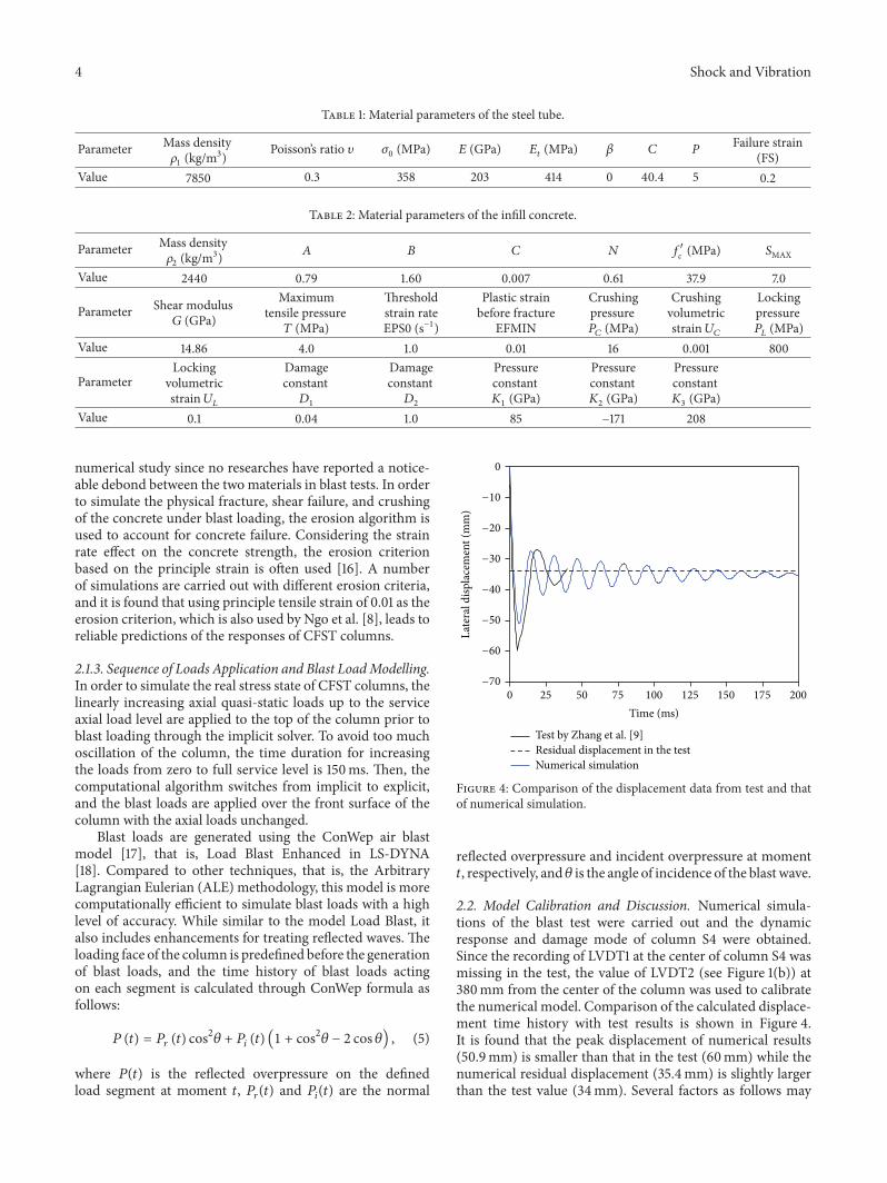
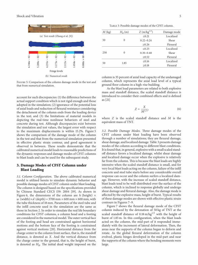
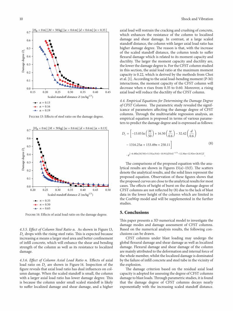
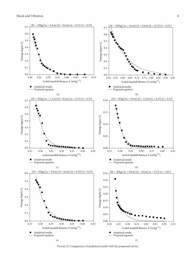

International Journal of
AerospaceEngineeringHindawi Publishing Corporationhttpwwwhindawicom Volume 2014
RoboticsJournal of
Hindawi Publishing Corporationhttpwwwhindawicom Volume 2014
Hindawi Publishing Corporationhttpwwwhindawicom Volume 2014
Active and Passive Electronic Components
Control Scienceand Engineering
Journal of
Hindawi Publishing Corporationhttpwwwhindawicom Volume 2014
International Journal of
RotatingMachinery
Hindawi Publishing Corporationhttpwwwhindawicom Volume 2014
Hindawi Publishing Corporation httpwwwhindawicom
Journal ofEngineeringVolume 2014
Submit your manuscripts athttpwwwhindawicom
VLSI Design
Hindawi Publishing Corporationhttpwwwhindawicom Volume 2014
Hindawi Publishing Corporationhttpwwwhindawicom Volume 2014
Shock and Vibration
Hindawi Publishing Corporationhttpwwwhindawicom Volume 2014
Civil EngineeringAdvances in
Acoustics and VibrationAdvances in
Hindawi Publishing Corporationhttpwwwhindawicom Volume 2014
Hindawi Publishing Corporationhttpwwwhindawicom Volume 2014
Electrical and Computer Engineering
Journal of
Advances inOptoElectronics
Hindawi Publishing Corporation httpwwwhindawicom
Volume 2014
The Scientific World JournalHindawi Publishing Corporation httpwwwhindawicom Volume 2014
SensorsJournal of
Hindawi Publishing Corporationhttpwwwhindawicom Volume 2014
Modelling amp Simulation in EngineeringHindawi Publishing Corporation httpwwwhindawicom Volume 2014
Hindawi Publishing Corporationhttpwwwhindawicom Volume 2014
Chemical EngineeringInternational Journal of Antennas and
Propagation
International Journal of
Hindawi Publishing Corporationhttpwwwhindawicom Volume 2014
Hindawi Publishing Corporationhttpwwwhindawicom Volume 2014
Navigation and Observation
International Journal of
Hindawi Publishing Corporationhttpwwwhindawicom Volume 2014
DistributedSensor Networks
International Journal of