Embed Size (px)
Citation preview

Numerical Studies on Performance of Composite Suction Piles in
Sand Subjected to Combined Loading
*San-Shyan Lin1), Yun-Chih Chiang2)
, Xin-Hua Lin3), Hsing-Yu Wang4) and Sung-Shan
Hsiao5)
1), 3), 4), 5)Dept. of Harbor and River Eng., National Taiwan Ocean University, Keelung,
Taiwan 20224 2)General Education Center, Tzu Chu University, Hua-Lien, Taiwan.
ABSTRACT
In order to increase the overall bearing capacity of a wind turbine foundation, a composite type of suction pile is proposed in this paper. Numerical analysis of a suction pile with enlarged lid size subjected to combined lateral and axial loading is presented in the paper. Analysis results prove a suction pile with enlarged lid size has better performance on both the overall bearing capacity and the stability of the foundation.
1. INTRODUCTION
A typical suction pile, or called suction bucket foundation, structure consists of
steel cylinder with diameter D, skirt length L with thickness ts, and an upper steel lid with
thickness tl as shown in Fig. 1. The suction pile was used as the foundation of a 3MW
wind turbine in 2002 in Denmark. Since then, more suction piles have been adopted as
foundation of off-shore wind turbine. Designing of this type of foundation needs to
consider large lateral loading and overturning moment. Under extreme condition, this
type of foundation has to carry lateral loading up to 60% of its axial loading (Housby et al.
2005)
1), 2), 5)
Professor
3) Graduate Student
4) Ph.D Candidate

In order to provide enough bearing capacity and stability, the main challenge of the
suction pile needs to be installed deeply enough. Hence, a suction or negative pressure
needs to be supplied inside the bucket to mobilize the pile bucket into desired depth.
The relationship between the required suction and the penetration resistance of a
suction bucket in sand was studied by Anderson et al. (2008) by the bearing capacity
theory, the triaxial shear test, cone penetration test, and laboratory model test. The
research results show that the penetration resistance decreases with increasing of
suction pressure. Also, decreasing of the relative density of the sand inside the bucket
increases permeability of the sand, in which the variation of hydraulic gradient
decreases the frictional resistance between the soil and the inside bucket wall.
In addition to study the bearing capacity of the suction pile by the upper bound limit
method, centrifuge test was also conducted by Zhang et al. (2010) to verify the accuracy
of the used theoretical method.
Villalobos et al. (2005) used small scale model test to investigate the bending
resistance of the suction bucket installed in saturated dense sand under different
installation methods. It was found that the bending resistance installed by suction is
smaller than that of pushing method. Small scale model test was also used by.
Villalobos et al. (2009) investigated the performance of the suction pile in dry sand,
with length to diameter ratio of 0.5 and 1.0, subjected to composite loading. The yielding
point was defined by the authors from the obtained load-displacement curves.
Comparison on the performance of the full scale or the small scale suction piles,
installed in sand or in clay subjected to vertical loading or bending moment, Kelly et al.
(2009) found that tested results appeared to have significant difference.
Utilizing the centrifuge and the in-situ test results, the finite element method was
used by Tran and Randolph (2008) to simulate the installation of the suction bucket
installed in sand. A linear relationship was found between the suction pressure and the
installed depth. In addition, it was also found the slope of the linear relationship is a
function of the critical hydraulic gradient inside the bucket.
Performance of a laterally loaded suction pile installed in sand was studied by
Achmus et al. (2013) using the finite element method. It was found that increasing of the
lateral loading up to a certain magnitude will cause separation between the lid and the
soil below the lid. Once the lateral loading or the rotation of the foundation up to a
certain value, complete separation between the lid and the soil below may occur.
Uplift capacity of the suction pile in sand was studied by Houlsby et al. (2005). A
simplified uplift bearing capacity equation was also proposed by the authors.

Small scale tests of suction piles subjected to combined loading were conducted
by Ibsen et al. (2014) in Aalborg University in Denmark. It was found that the bearing
capacity of the suction pile depends on the ratio of installed depth. Calibration of the
failure criteria were also conducted by comparing to the results of the tested results
A series of small scale tests on the effects of suction installation and jacking
installation on the interaction between suction bucket and inside soil were studied by
Lian et al. (2014). Under h/D<0.3 (h= various depth of bucket and D= diameter of the
bucket), it is shown that the soil pressures either inside or outside the skirt have the
same magnitude. However, when h/D>0.3, the inside soil pressure is larger than that of
the outside pressure. If the suction pile is installed by suction, the inside soil pressure
drops when the suction is steadily applied. The outside soil pressure increases
immediately after application of the suction, and then drops to a steady condition.
Effects of wind or wave on performance of suction piles, laboratory tests on small
scale suction piles subjected to cyclic lateral loading were conducted by Byrne and
Houlsby (2004). The axial loading was considered as constant magnitude. The test
result showed the rate of cyclic lateral loading has no effect on the load vs displacement
relationship of the tested suction pile.
Small scale tests were conducted by Zhu et al. (2013) to investigate the
performance of a suction pile in loose sand subjected to 10,000 cycles of loading. The
main concern was the accumulated rotation angle, settlement and stiffness of the
foundation due to cyclic loading. The test results show the settlement increases with
increasing of the loading cycle. However, the numbers of loading cycle has little effect
on the foundation stiffness. It was also found that a cyclic loading regime intermediate
between one-way and full two-way cycling produced the largest rotations.
Centrifuge was used again by Tran et al. (2007) to investigate the effect of a silty
soil layer sandwiched between two sand soils on the penetration resistance of a suction
pile. The results show more suction was needed for the soil contained silt than that of
sand only.
Dynamic and static full scale pullout tests of suction piles were conducted by
Ravichandran et al. (2014). The in situ condition includes natural effects of wind, wave
and current. The tested results show the pullout capacity is affected by the geometry of
the test pile, pullout angle and whether the loading was static or dynamic. It was also
observed that the pullout angle has no effect on performance of the large diameter
suction pile.
Installation of a suction pile does not need impact loading and ocean bed levelling.

In addition, the suction pile can easily be removed after the wind turbine lost its function.
Hence, overall construction of a suction pile is not only cheaper but also less time
consuming compared to other types of wind turbine foundation. It satisfies both low cost
and low environmental impact. However, one important concern of the suction pile is its
overturning stability when subjected to lateral loading. Hence, a composite type of
suction pile is proposed in this paper in order to increase the overall bearing capacity of
the foundation. By increasing the diameter of the lid of a suction pile up to a certain size,
such as Dl of Fig. 1, the new type of composite foundation is expecting to have a more
stable and a higher bearing capacity performance. This paper presents the numerical
simulated results of suction piles with enlarged lid size for improving its bearing capacity
and stability when subjected to combined lateral and axial loading.
Fig. 1 Composite suction foundation geometric model
2. FINITE ELEMENT MODEL
Performance of the proposed composite foundation is studied by using available
three dimensional finite element software, PLAXIS 3D (2013). A schematic illustration of
a composite suction pile is shown in Fig. 1. Once the lid size, Dl, is reduced to the
diameter of the suction bucket, the composite suction foundation becomes a usual
suction pile. As suggested by Achmus et al. (2013), in order to reduce the size effect at
the simulation boundary, the size of the finite element mesh is assumed to reach the
boundary at 6.67 times the diameter of the lid as shown in Fig. 2. Also, the boundary at
the bottom is set at 3 times of the bucket depth.

Fig. 2 The boundary of the finite element model
The Mohr-Coulomb model is used to simulate the behavior of the soil. The
interface element is used to simulate the interaction between the soil and the foundation
structure. The parameter, 𝑅𝑖𝑛𝑡𝑒𝑟, is set as 0.67 as the criterion to control the relative
displacement between the soil and the structure. Hence, the strength at the
soil/structure interface can be expressed as 𝐶𝑖𝑛𝑡𝑒𝑟 = 𝑅𝑖𝑛𝑡𝑒𝑟 × 𝐶𝑠𝑜𝑖𝑙 ; tan ∅𝑖𝑛𝑡𝑒𝑟 = 𝑅𝑖𝑛𝑡𝑒𝑟 ×
tan ∅𝑠𝑜𝑖𝑙 , in which Cinter and ψinter are the cohesion and the friction angle at the
soil-structure interface.
Two different densities of the sandy soil are used for analyses. Drained condition
is considered for both soils. For dense sand, the unit weight γ = 10.2 kN/m3, Poisson’s
ratio 𝜈 = 0.25, internal friction angle ∅ = 40°, and angle of dilatancy ψ = 10°. In addition,
a small cohesion c = 0.1 and interface friction angle reduction parameter 𝑅𝑖𝑛𝑡𝑒𝑟 = 0.67.
For medium dense sand, unit weight γ = 9 kN/m3, Poisson’s ratio 𝜈 = 0.25, internal
friction angle ∅ = 35°, angle of dilatancy ψ = 5°, cohesion c = 0.1, and 𝑅𝑖𝑛𝑡𝑒𝑟 = 0.67.
The geometry and material properties of the simulated composite suction pile is
given in Fig. 1 and Table 1. In order to simulate the lid as a more rigid plate, whose
elastic modulus is assumed as 109 GPa.

Table 1 Composite suction foundation parameter definition
Diameter of the upper lid, 𝑫𝒍 (m) 12, 16, 20, 24
Material Steel
Buoyant unit weight (kN/m3) 68
Elasticity Modulus of lid, E(GPa) 109
Elasticity Modulus of skirt, E(GPa) 210
Diameter of the suction bucket, D(m) 12
Skirt length, L(m) 6 9 12
L/D 0.5 0.75 1
Skirt thickness, ts(m) 0.03
Lid thickness, tl(m) 0.1
The finite element analysis includes three stages. The initial stage considers the
self-weight of the soil mass itself. The at-rest earth pressure coefficient 𝑘0 = 1 − sin ∅
is used. Subsequently, applying the self-weight of the foundation structure and then
finally the external load application. The external load includes axial loading, V, lateral
loading, H, and bending, M. The applied loads are applied at the center of the lid with
the coordinates of (0, 0, 0). Assuming the simulating weight is a 5MW wind turbine, the
axial loading is fixed as10MN in the analysis. The moment is controlled by the lateral
load, H, and the eccentricity, h, as shown in Fig.3.
Fig. 3 Composite suction foundation loading definition schematic diagram

3. VERIFICATION OF THE FINITE ELEMENT MODEL
Load-bearing behavior of suction bucket foundation in sand studied using different
finite element code, ABAQUS, by Achmus et al. (2013) is used to verify the model of the
finite element code in this paper. The parameters used for numerical analyses are also
followed the assumptions made by Achmus et al. (2013). Comparison on the results
analyzed by ABAQUS and PLAXIS of a suction bucket with length/diameter ratio
L/D=0.75 subjected to axial loading V=10MN under different eccentricity (h=0m, h=20m
and h=30m) is shown in Fig. 4. Good correlation on the relationships between horizontal
load vs displacement obtained from both methods is shown in the figure.
Fig. 4 Verification with Achmus(2013) when L/D=0.75,vertical load V=10MN with
different load eccentricity
4. NUMERICAL SIMULATION
Sandy soil with two different densities, dense and medium dense sand, are
considered in the following parametric numerical simulations. The geometry of the
composite foundation is assumed to be the combination of various lid diameter (Dl=12m,
16m, 20m, or 24m) with bucket length (L= 6m, 9m, or 12m under fixed value of D= 12m).
Assumed material properties of the suction bucket for analysis are given in Table 1. A
vertical loading of 10MN is applied to simulate the weight of a 5MW wind turbine. In
0
5
10
15
20
25
30
35
40
45
0 0.2 0.4 0.6 0.8 1 1.2
Ho
rizo
nta
l lo
ad(M
N)
Displacement(m)
Achmus(2013),h=0m
Achmus(2013),h=20m
Achmus(2013),h=30m
this study,h=0m
this study,h=20m
this study,h=30m
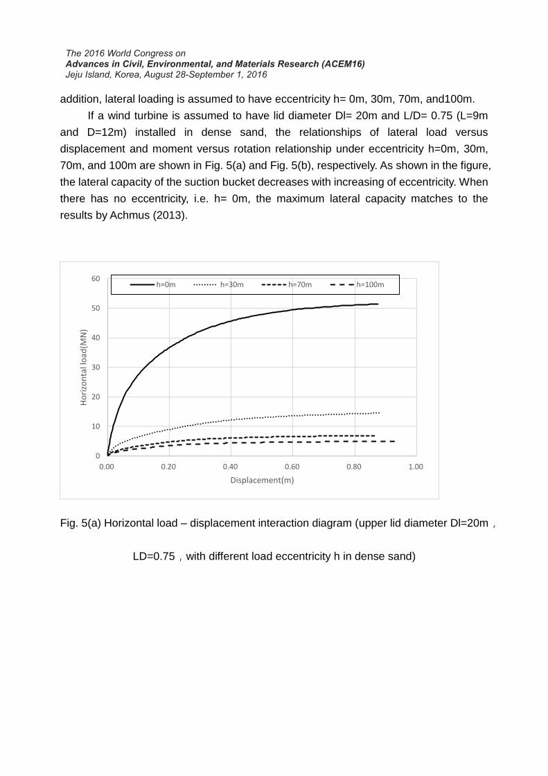
addition, lateral loading is assumed to have eccentricity h= 0m, 30m, 70m, and100m.
If a wind turbine is assumed to have lid diameter Dl= 20m and L/D= 0.75 (L=9m
and D=12m) installed in dense sand, the relationships of lateral load versus
displacement and moment versus rotation relationship under eccentricity h=0m, 30m,
70m, and 100m are shown in Fig. 5(a) and Fig. 5(b), respectively. As shown in the figure,
the lateral capacity of the suction bucket decreases with increasing of eccentricity. When
there has no eccentricity, i.e. h= 0m, the maximum lateral capacity matches to the
results by Achmus (2013).
Fig. 5(a) Horizontal load – displacement interaction diagram (upper lid diameter Dl=20m,
LD=0.75,with different load eccentricity h in dense sand)
0
10
20
30
40
50
60
0.00 0.20 0.40 0.60 0.80 1.00
Ho
rizo
nta
l lo
ad(M
N)
Displacement(m)
h=0m h=30m h=70m h=100m

Fig. 5(b) Moment – rotation interaction diagram (upper lid diameter
Dl=20m,L/D=0.75,with different load eccentricities h in dense sand)
Considering four different lid sizes, with fixed skirt length of 9m and eccentricity of
30m, the normal stress distribution outside and inside the bucket skirt is shown in Fig. 6.
The effective normal stress on the right skirt increases with increasing of D1.
Comparison between Fig. 6(a) and Fig. 6(d), we can find that the normal stress inside
the right skirt is smaller than that of the outside skirt. Comparison between Fig. 6(a) and
Fig. 6(c) we can find that the normal stress below the rotating center is much higher due
to the effect of passive earth pressure. In addition, Fig. 6(b) also shows that the rotating
center is higher when the lid size, D1, is larger. Hence, increasing the lid size will have
higher bending moment resistance.
0.00
100.00
200.00
300.00
400.00
500.00
0.00 0.50 1.00 1.50 2.00 2.50 3.00 3.50
Mo
men
t(M
N-m
)
Rotation Θ(。)
h=30m h=70m h=100m pure moment

(a) right skirt (inside) (b) right skirt (outside)
(c) left skirt (outside) (d) left skirt (inside)
Fig. 6 Composite suction foundation with different Dl(when bucket length L=9m , load
eccentricity h=30m),bucket skirt effective normal stress distribution
The failure modes of the composite suction caisson with lid size D1=12m and
D1=24m are shown in Fig. 7. As shown in Fig. 7(a) for the case with D1=12m and
L/D=0.5, inclination of the bucket also induces the passive failure on the right skirt and
the separation between the bucket and the soil on the left skirt. A rotating center at right
bottom corner is observed from Fig. 7(b) and Fig. 7(c). Passive failure mode is observed
for the skirt on top of the respect rotating center.
For the larger lid size of D1=24m and L/D=0.5, the numerical study result shows
the uplifting of the soil on top of the right side lid as shown in Fig. 7(d). In addition, a
passive failure is observed on the left skirt. Observation from Fig. 7(e) and 7(f) we can
also find the rotating center is higher when the D1 is larger. It shows Dl=24m case
appears to have higher bending resistance.

(a)Dl=12m, L/D=0.5
(d) Dl=24m, L/D=0.5
(b) Dl=12m, L/D=0.75
(e) Dl=24m, L/D=0.75
(c) Dl=12m, L/D=1
(f) Dl=24m, L/D=1
Fig. 7 In comparison to the displacement of the composite suction foundation upper lid
diameter Dl=12m,24m with different bucket L/D when load eccentricity h=70m in dense
sand
Fixed h=30m and D1=20m, variation of lateral capacity under different bucket
length (L=6m, 9m, and12m; and L/D=0.5, 0.75, and 1) is shown in Fig. 8. Whether the
soil condition is dense or medium dense, we can find the lateral capacity increases with
increasing of bucket length. At the displacement 0.8m, the lateral capacity increases
about 63.5%~72.9% when the bucket length increasing from 6m to 9m. For the case
increasing from 9m to 12m, the capacity increases about 44.1%~46.9%.

(a) in dense sand (b) in medium dense sand
Fig. 8 Horizontal load–displacement interaction diagram (upper lid diameter Dl=20m,
load eccentricity h=30m,with different bucket length)
Fixed h=30m and L=9m, variation of lateral capacity under different lid diameter
(Dl=12m,16m, 20m, and 24m) is shown in Fig. 9. As shown in the figure, the lateral
capacity increases with increasing of lid size. At the displacement 0.8m, the lateral
capacity increases about 25.8%~49.7% when the bucket length increasing from 12m to
16m.
(a) in dense sand (b) in medium dense sand
Fig. 9 Horizontal load–displacement interaction diagram (L/D=0.75,load eccentricity
h=30m,with different upper lid diameter Dl)
If we assume h=30m and D1=20m, the moment versus rotation relationships

under different bucket length (L=6m, 9m, and12m; and L/D=0.5, 0.75, and 1) are shown
in Fig. 10. Increasing the bucket length also increases the bending resistance of the
bucket. Under the same moment (M=150MN-m), the rotation angle under bucket length
of L=6m, L=9m, and L=12m is 0.6, 0.3 and 0.14 degree, respectively.
(a) in dense sand (b) in medium dense sand
Fig. 10 Moment–rotation interaction diagram (upper lid diameter Dl=20m,load
eccentricity h=30m,with different bucket length)
The relationships of moment versus rotation of the foundation with h=30m and
L=9m under various lid size (Dl=12m,16m, 20m, and 24m) are shown in Fig. 11. The
figures showed the bending moment resistance of the foundation increases with
increasing of the lid size, whether in medium dense sand or dense sand. Based on Figs.
10 and 11 we can find that the bending moment resistance of the foundation is improved
by increasing the size of the lid or the length of the bucket.
(a) in dense sand (b) in medium dense sand
Fig. 11 Moment–rotation interaction diagram (L/D=0.75,load eccentricity h=30m,with

different upper lid diameter Dl)
5. CONCLUSIONS
In this paper, a proposed composite foundation in medium dense sand or in dense
sand subjected to combined loading is investigated using numerical simulation. The
conclusions based on the results of the numerical studies can be drawn as in the
following:
1. The rotating center of the foundation appeared to be higher under larger applied
moment resulted from larger eccentricity. In addition, the lateral capacity of the
foundation decreases when the bending.
2. Based on the variation of the effective normal stress on either side of the bucket,
higher normal stress was observed below rotating center due to higher passive soil
pressure. However, the effective normal stress above the rotating center appeared
to be linearly increased along depth. In addition, the rotating center of the
foundation appeared to be higher with increasing of the lid diameter (Dl).
3. Based on the failure mechanism of the composite foundation with D1=12m, the
foundation not only inclined under combing loading but also displaced in the
horizontal direction. The soil condition on the right side of the bucked appeared to
be passive failure while on the left side bucket appeared to have separation
between soil and bucket. Above the rotating center of the bucket, passive failure
was observed. For the composite foundation with D1=24m, uplifting of the soil was
observed on the right side of the lid. In addition, passive failure was observed on
the left side of the bucket. The rotating center of the D1=24m case was higher than
that of the D1=12m case, which indicated that the composite foundation has higher
bending moment resistance than that of the conventional bucket foundation.
4. The lateral capacity of the composite foundation improved with increasing lid
diameter or bucket depth. The foundation rotating degree became lower with
increasing of lid diameter or bucket depth. Hence, the bending moment resistance
of the composite foundation was also increased.
REFERENCES
Achmus, M., Akdag, C.T., Thieken, K. (2013), “Load-bearing behavior of suction bucket

foundations in sand. ”Ocean Research.43,157-165.
Andersen, K.H., Jostad,H.P., Dyvik,R.(2008), “Penetration resistance of offshore skirted
foundation sand anchors in dense sand. ”J.Geotech.Geoenviron.Eng. 134(1),106–
116.
Byrne, B.W., Houlsby, G.T. (2004), “Experimental Investigations of the response of
suction caissons to transient combined loading. ”J.Geotech.
Geoenviron.Eng.2004.130.pp240-253.
Houlsby,G.T., Ibsen,L.B., Byrne,B.W.(2005), “Suction caissons for wind turbines. ”Key
note lecture.In:Proceeding sof the International Symposiumon Frontiers in Offshore
Geotechnics.Perth,Western Australia,75–94.
Houlsby, G.T., Richard, B., Kelly, R.B., Byrne, B.W.(2005),“The tensile capacity of
suction caissons in sand under rapid loading. ”ISFOG 2005,405-410.
Ibsen, L.B., Larsen, K.A., Barari. (2014), “Calibration of failure criteria for bucket
foundation on drained sand under general loading. ”J.Geotech.
Geoenviron.Eng.2014.140(7).
Jaky, J.(1944), “The coefficient of earth pressure at-rest. ” Journal of Society of
Hungarian Architects and Engineers, 355–358.
Kelly, R.B., Houlsby, G.T., Byrne, B.W. (2006), “ A comparison of field and laboratory
tests of caisson foundations in sand and clay. ” Geotechnique. 56(9),617–626.
Lian, J., Chen, F., Wang, H. (2014), “Laboratory tests on soil-skirt interaction and
penetration resistance of suction caissons during installation in sand. ”Ocean
Engineering.84(2014),1-13.
Plaxis user’s manual,version2013.
Ravichandran, V., Ramesh, R., Babu, S.M., Ramadass, G.A., Ramanamoorthy,
Atmanand, M.A.(2014), “Field scale tests for determination of pullout capacity of
suction pile anchors under varying loading conditions. ”Geotechnical Engineering
Journal of the SEAGS & AGSSEA.2014.45(3).49-51.
Tran, M.N., Randolph, M.F.(2008) “Variation of suction pressure during caisson
installation in sand. ” Geotechnique. 58(1),1-11
Tran, M.N., Randolph, M.F., Airey, D.W.(2007), “Installation of suction caissons in sand
with silt layers. ” J.Geotech. Geoenviron.Eng.2007.133,1183-1191.
Villalobos, F.A., Byrne, B.W., Houlsby, G.T.(2005), “Moment loading of caissons installed
in saturated sand. ”In: Proceedings of international symposium on frontiers in
Geotechnics, ISFOG. University of Western;411–16 .
Villalobos, F.A., Byrne, B.W., Houlsby, G.T. (2009), “An experimental study of the

drained capacity of suction caisson foundations under monotonic loading for offshore
applications. ”Soils and Foundations;49:477–88 .
Zhang, J.H., Chen, Z.Y., Li, F. (2010), “Three dimensional limit analysis of suction bucket
foundations. ”Ocean Engineering;37:790–9 .
Zhu, B., Byrne, B.W., Houlsby, G.T. (2013), “Long-term lateral cyclic response of suction
caisson foundation in sand. ”J.Geotech. Geoenviron . Eng . 2013 . 139 , 73-83