Embed Size (px)
Citation preview
Journal for Technology of Plasticity, Vol. 36 (2011), Number 2
DOI: 10.2478/v10211-011-0010-3
NUMERICAL SIMULATION OF THE PLUNGE STAGE IN FRICTION STIR WELDING ALLOYS EN AW 2024 T
351 AND EN AW 7049A T 652
Darko Veljić1, Milenko Perović2, Aleksandar Sedmak3 and Marko Rakin4
1IHIS Science & Technology Park Zemun, Belgrade, Serbia
2Chamber of Economy of Montenegro, Podgorica, Montenegro 3Faculty of Mechanical Engineering University of Belgrade, Serbia
4Faculty of Technology and Metallurgy University of Belgrade, Serbia
ABSTRACT
This paper investigates the plunge stage using numerical modeling. Change of temperature and plunge force have been analyzed during the plunge stage of the FSW procedure for high hardness aluminium alloys EN AW 2024 T 351 and EN AW 7049A T 652, at different speed of tool rotation. Numerical results indicate that the maximum temperature in the FSW process can be increased with the increase of the rotational speed and that temperature is lower than the melting point of the welding material. Higher temperature was registered at the aluminum alloy EN AW 2024 T 351 at the same speed of tool rotation, and higher plunge force – resistance of material was registered at the alloy EN AW 7049A T 652. When the rotational speed is increased, the plunge force can be reduced. A three-dimensional finite element model (FEM) of the plunge stage was developed using the commercial code ABAQUS to study the thermo-mechanical processes involved during the plunge stage. A coupled thermo-mechanical 3D FE model using the arbitrary Lagrangian–Eulerian formulation, the Johnson–Cook material law and the Coulomb’s Law of friction. In this analysis, temperature, displacement and mechanical responses are determined simultaneously. The heat generation in FSW can be divided into three parts: frictional heat generated by the tool shoulder, frictional heat generated by the tool pin, and heat generated by material plastic deformation near the pin region. Keywords: friction stir welding, thermo-mechanical model, process parameters, plunge stage, temperature file
98
Journal for Technology of Plasticity, Vol. 36 (2011), Number 2
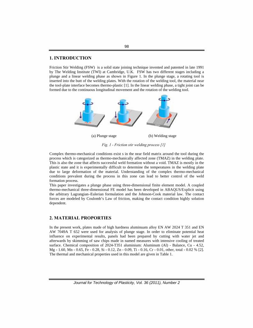
1. INTRODUCTION
Friction Stir Welding (FSW) is a solid state joining technique invented and patented in late 1991 by The Welding Institute (TWI) at Cambridge, U.K. FSW has two different stages including a plunge and a linear welding phase as shown in Figure 1. In the plunge stage, a rotating tool is inserted into the butt of the welding plates. With the rotation of the welding tool, the material near the tool-plate interface becomes thermo-plastic [1]. In the linear welding phase, a tight joint can be formed due to the continuous longitudinal movement and the rotation of the welding tool.
(a) Plunge stage (b) Welding stage
Fig. 1 - Friction stir welding process [1]
Complex thermo-mechanical conditions exist s in the near field matrix around the tool during the process which is categorized as thermo-mechanically affected zone (TMAZ) in the welding plate. This is also the zone that affects successful weld formation without a void. TMAZ is mostly in the plastic state and it is experimentally difficult to determine the temperatures in the welding plate due to large deformation of the material. Understanding of the complex thermo-mechanical conditions prevalent during the process in this zone can lead to better control of the weld formation process. This paper investigates a plunge phase using three-dimensional finite element model. A coupled thermo-mechanical three-dimensional FE model has been developed in ABAQUS/Explicit using the arbitrary Lagrangian–Eulerian formulation and the Johnson-Cook material law. The contact forces are modeled by Coulomb’s Law of friction, making the contact condition highly solution dependent.
2. MATERIAL PROPORTIES
In the present work, plates made of high hardness aluminuam alloy EN AW 2024 T 351 and EN AW 7049A T 652 were used for analysis of plunge stage. In order to eliminate potential heat influence on experimental results, panels had been prepared by cutting with water jet and afterwards by skimming of saw chips made in named measures with intensive cooling of treated surface. Chemical composition of 2024-T351 aluminium: Aluminum (Al) - Balance, Cu - 4.52, Mg - 1.60, Mn - 0.65, Fe - 0.28, Si - 0.12, Zn - 0.09, Ti - 0.16, Cr - 0.01, other, total - 0.02 % [2]. The thermal and mechanical properties used in this model are given in Table 1.

99
Journal for Technology of Plasticity, Vol. 36 (2011), Number 2
Tabele 1: Material properties of EN AW 2024 T 351 [2],[3]
Material properties Value
Young's Modulus of Elastic. (GPa) 73.1
Poisson´s Ratio 0.33
0,2% Yield strength R0,2, MPa 270
Tensile strength Rm, MPa 410
Thermal Conductivity (W/mK) 121
Coefficient of Thermal Expansion (°C¯¹) 24.7x10¯6
Density (kg/m³) 2770
Specific Heat Capacity (J/Kg °C) 875
Solidus (°C) 502
Liquidus (°C) 638 Chemical composition of EN AW 7049A-T652 aluminium done using OE quantmeter ARL with electronic samples “Pechiney is as follows: Aluminum (Al) – Balance, Cu – 1.45, Mg – 2.15, Mn – 0.27, Fe – 0.23, Si – 0.10, Zn – 7.20, Ti – 0.015, Cr – 0.13, Zr – 0.13, V – 0.004, B – 0.003. The thermal and mechanical properties used in this model are given in Table 2. The material of the tool is steel x155CrVMo121. The material of the backing plate is steel 42CrMo4.
Table 2 : Material properties of EN AW 7049 AT652 [4]
Material properties Value
Young's Modulus of Elastic. (GPa) 72
Poisson´s Ratio 0.33
0,2% Yield strength R0,2, MPa 570
Tensile strength Rm, MPa 650
Thermal Conductivity (W/mK) 154
Coefficient of Thermal Expansion (°C¯¹) 23.4x10¯6
Density (kg/m³) 2820
Specific Heat Capacity (J/Kg °C) 960
Temperature melt (°C) 477
Elongantion A, % 10

100
Journal for Technology of Plasticity, Vol. 36 (2011), Number 2
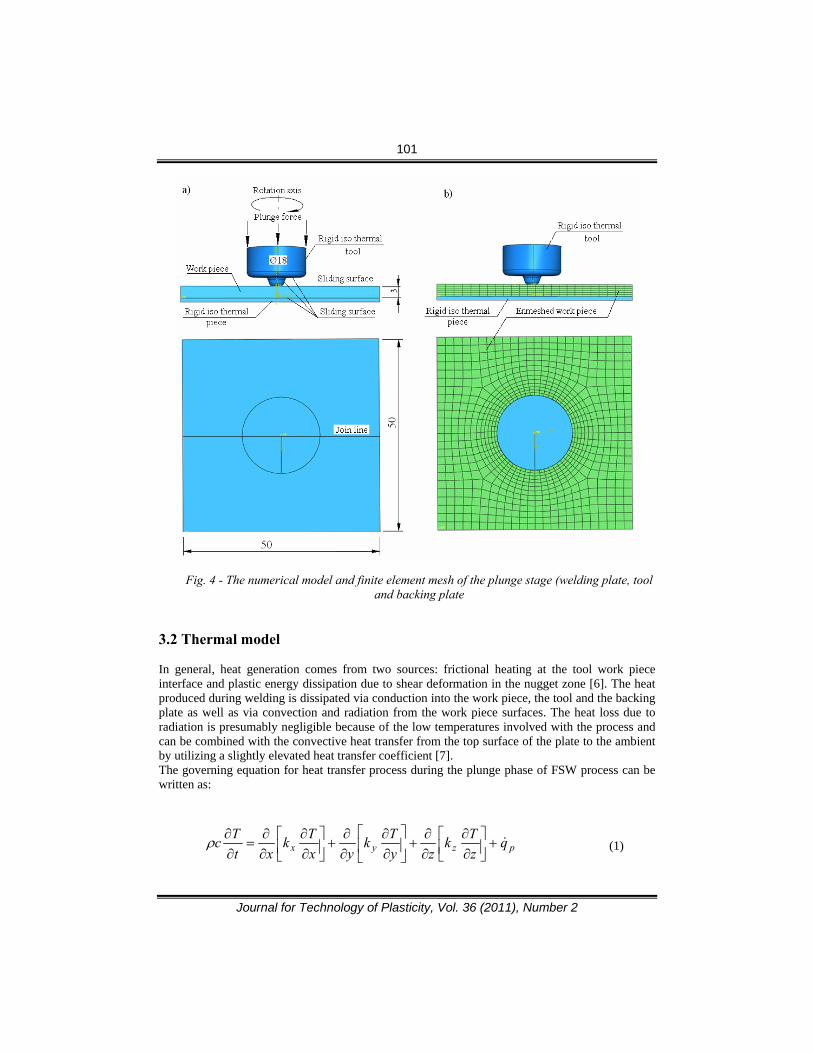
3. MODEL DESCRIPTION 3.1 Geometry and finite element mesh The welding plate in the numerical model of the plunge stage is dimension 50 x 50 x 5mm. For three-dimensional numerical model used is C3D8RT element type which is a thermo-mechanically coupled hexahedral element with 8-nodes each having trilinear displacement and temperature degrees of freedom. This element produces uniform strain (first-order reduced integration) and contains hourglass control [5]. The mesh consists of 23608 nodes and 20972 elements. The tool and the backing plate are modeled as a rigid surface having no thermal degrees of freedom. The main tool geometry in the FE model is similar to the experimental tool, figure 2. The numerical model of welding plate, tool and backing plate is shown in figure 3.
Fig.2 - The welding tool which is used in experimentand numerical analysis
Fig.3 - The numerical model of welding plate, tool and backing plate Figure 4 shows the projection of assembled geometric and numerical models for plunge stage. Dimensions of the model, sliding surface and assigned movements are given.
101
Journal for Technology of Plasticity, Vol. 36 (2011), Number 2
Fig. 4 - The numerical model and finite element mesh of the plunge stage (welding plate, tool and backing plate
3.2 Thermal model
In general, heat generation comes from two sources: frictional heating at the tool work piece interface and plastic energy dissipation due to shear deformation in the nugget zone [6]. The heat produced during welding is dissipated via conduction into the work piece, the tool and the backing plate as well as via convection and radiation from the work piece surfaces. The heat loss due to radiation is presumably negligible because of the low temperatures involved with the process and can be combined with the convective heat transfer from the top surface of the plate to the ambient by utilizing a slightly elevated heat transfer coefficient [7]. The governing equation for heat transfer process during the plunge phase of FSW process can be written as:
pzyx qzTk
zyTk
yxTk
xtTc &+⎥⎦
⎤⎢⎣⎡
∂∂
∂∂
+⎥⎦
⎤⎢⎣
⎡∂∂
∂∂
+⎥⎦⎤
⎢⎣⎡
∂∂
∂∂
=∂∂ρ (1)

102
Journal for Technology of Plasticity, Vol. 36 (2011), Number 2
where ρ is the density, c is the specific heat, k is heat conductivity, T is the temperature, t is the time, pq& is heat generation coming from plastic energy dissipation due to shear deformation, and x, y, and z are spatial coordinate. The rate of heat generation due to plastic energy dissipation, pq& is computed from
plpq εησ && = (2)
where η is the factor of converting mechanical to thermal energy (0.9) [8], σ is the shear stress,
and plε& is the rate of plastic strain. Heat generation of frictional heating between tool and workpieces can be written as:
32
34 PNRq f μπ=& (3)
where fq& is the frictional heat generation, μ is the coefficient of friction, P is the traction, N is the rotational speed and R is the surface radius. 3.3 Johnson-Cook elastic–plastic model Johnson-Cook elastic–plastic model is empirically based. He calculates the flow stress as a function of temperature and strain rate up to the melting point or solidus temperature. For EN AW 2024 T 351 and EN AW 7049A T 652 the solidus temperature is set to 502 °C and 477 °C. The elastic–plastic Johnson–Cook material law is given by [7]:
[ ] )1(1)(m
roommelt
room
o
pnpy TT
TTCBA ⎟⎟
⎠
⎞⎜⎜⎝
⎛−
−−
⎥⎥⎦
⎤
⎢⎢⎣
⎡⎟⎟⎠
⎞⎜⎜⎝
⎛++=
εε
εσ&
& (4)
where is: - For EN AW 2024 T 351 Tmelt =502 (°C) the melting point or solidus temperature, Troom
=20 (°C) the ambient temperature, T(°C) the effective temperature, A=265(MPa) the yield stress, B=426(MPa) the strain factor, n=0.34 the strain exponent, m=1 the temperature exponent, C=0.015 the strain rate factor.
- For EN AW 7049A T 652 Tmelt =477 (°C) the melting point or solidus temperature, Troom =20 (°C) the ambient temperature, T(°C) the effective temperature, A=503(MPa) the yield stress, B=350(MPa) the strain factor, n=0.4 the strain exponent, m=1.5 the temperature exponent, C=0.12 the strain rate factor.
A, B, C, n, Tmelt and m are material/test constants for the Johnson–Cook strain rate dependent yield stress for EN AW 2024 T 351 and EN AW 7049A T 652 The model was developed to study the temperature fields and the plunge force of EN AW 2024 T 351 and EN AW 7049A T 652 for different rotating speed: 400 and 500 r/min, during the plunge stage in friction stir welding (FSW) process. Figure 5 shows the coordinates of points, T1 (9.5,0,0) and T2(12,0,0), for measuring the temperature dependence of the time.

103
Journal for Technology of Plasticity, Vol. 36 (2011), Number 2
Fig.5 - The coordinates of points for measuring the temperature dependence of the time
4. RESULTS AND DISCUSSION Figure 6 and 7 shows the temperature fields in the transverse cross section near the tool/matrix interface after 11.6 and 14.5 s, when rotation speeds is 400 rpm of EN AW 2024 T 351 and EN AW 7049A T 652. The heat transfer through the bottom surface of the workpiece is controlled by the heat transfer coefficient of 1000W/m2 K. A constant friction coefficient of 0.3 is assumed between the tool and the workpiece and the penalty contact method is used to model the contact interaction between the two surfaces. Heat convection coefficients on the surface of the workpiece are h=10W/m2K with the ambient temperature of 200C [8]. This transient temperature field is symmetric.
a)
b)
Fig.6 - The temperature fields in the transverse cross section near the tool/matrix interface after 11.6 s, when rotation speeds is 400 r/min

104
Journal for Technology of Plasticity, Vol. 36 (2011), Number 2
Figure 7a shows that the maximum temperature is lower than the alloy EN AW 2024 T351 melting temperature - 502 °C, i.e. the welding process takes place in the solid state. The same can be observed in Figure 7c, where the welding temperature is lower than alloy EN AW 7049 T652 melting temperature - 477 °C. Figures 7a and 7b refer to the last stage in the process of plunging, after 14.5s, alloy EN AW 2024 T351, while the maximum temperature in Figure 7b is limited to 477 °C, in order to make comparison with the temperature profile of the alloy EN AW 7049 T652 shown in Figure 7c . Given that plunge parameters are exactly the same for plunge phases of both alloys (tool rotation speed is 400 rpm, the speed of tools penetration is 12mm/min), tool is the same and thicknesses is equal, it is concluded that in the welding zone, below the front side of the tool, there is a larger quantity of heat generated and higher temperature is generated in the alloy EN AW 2024 T351. This alloy has a higher melting temperature - 502 °C, so that above 477 °C, heat is still generating by friction and plastic deformation, which is not possible at alloy EN AW 7049 T652.
a)
b)
c)
Fig.7 - The temperature fields in the transverse cross section near the tool/matrix interface after 14.5 s, when rotation speeds is 400 r/min
105
Journal for Technology of Plasticity, Vol. 36 (2011), Number 2
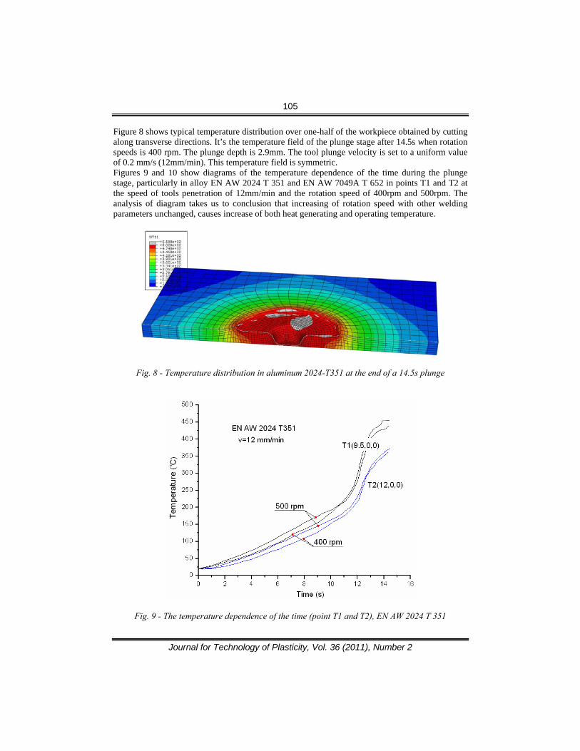
Figure 8 shows typical temperature distribution over one-half of the workpiece obtained by cutting along transverse directions. It’s the temperature field of the plunge stage after 14.5s when rotation speeds is 400 rpm. The plunge depth is 2.9mm. The tool plunge velocity is set to a uniform value of 0.2 mm/s (12mm/min). This temperature field is symmetric. Figures 9 and 10 show diagrams of the temperature dependence of the time during the plunge stage, particularly in alloy EN AW 2024 T 351 and EN AW 7049A T 652 in points T1 and T2 at the speed of tools penetration of 12mm/min and the rotation speed of 400rpm and 500rpm. The analysis of diagram takes us to conclusion that increasing of rotation speed with other welding parameters unchanged, causes increase of both heat generating and operating temperature.
Fig. 8 - Temperature distribution in aluminum 2024-T351 at the end of a 14.5s plunge
Fig. 9 - The temperature dependence of the time (point T1 and T2), EN AW 2024 T 351

106
Journal for Technology of Plasticity, Vol. 36 (2011), Number 2
Fig. 10 - The temperature dependence of the time (point T1 and T2), EN AW 7049A T 652
Figures 11 and 12 show diagrams of the temperature dependence of time during the plunge stage simultaneously for alloy EN AW 2024 T 351 and EN AW 7049 T 652 in points T1 and T2 at the speed of tools penetration of 12mm/min, particularly for rotation speeds 400rpm and 500rpm. The analysis of diagram takes us to conclusion that at the same parameters of plunge stage, temperatures are higher in alloy EN AW 2024 T 351, which is explained by analyzing of Figures 7b and 7c. Figure 13 shows the plunge force dependence of the time during the plunge stage of the friction stir welding (FSW) process. At the start of FSW, during initial plunging, due to lack of generated heat, deformation strengthening occurs, leading to increase of force, Pos1. After establishing of contact between the rotating pin and the welding plate, the generated heat starts to increase the temperature. This temperature increase decreases the resistance to deformation, both though easier cross-slip and possible recovery and/or recrystallization. Resulting behaviour is the decrease of force with prolongation of time. This trend continues until the moment of contact between tool shoulder and the welding plate when the force experience sharp increase and further equally sharp decrease. The increase is related to friction between cold tool shoulder and welding plate. Again cold deformation and work hardening occurs prior to heating introduced by friction. The intensive heat generation leads deformation under high temperatures, resulting in decrease of resistance to deformation, i.e. to sharp fall of force. Also, it can be seen that resistance to tools penetration in material of the alloy EN AW 7049A T 652 is higher than in alloy EN AW 2024 T 351 which can be expected, taking into account mechanical properties of these two alloys (Tables 1 and 2). When the rotational speed is increased, the plunge force can be reduced.

107
Journal for Technology of Plasticity, Vol. 36 (2011), Number 2
Fig. 11 - The temperature dependence of the time (point T1 and T2), EN AW 7049A T 652 and EN AW 2024 T 351, the rotational speed is 400 rpm
Fig. 12 - The temperature dependence of the time (point T1 and T2), EN AW 7049A T 652 and EN AW 2024 T 351, the rotational speed is 500 rpm

108
Journal for Technology of Plasticity, Vol. 36 (2011), Number 2
Fig.13 - The force dependence of the time during the plunge stage and the linear welding phase 5. CONCLUSIONS
When the rotational speed is increased, the region in higher temperature can be increased. The temperature in the matrix is lower than the melting temperature. The temperature field is symmetric. At the same welding parameters, higher quantity of heat is generated which causes higher temperature growth in the alloy EN AW 2024 T 351 than in the alloy EN AW 7049A T 652. Resistance to tools penetration into material is higher in the alloy EN AW 7049A T 652 than in the alloy EN AW 2024 T 351. When the rotational speed is increased, the plunge force can be reduced. REFERENCES
[1] Veljic, D. (2006). Technology of Friction Stir Welding of Aluminium Alloys. M.Sc. Thesis,
Faculty of Mechanical Engineering, University of Belgrade, May 2006. [2] Certificate conformity, ALCOA International, Inc, Approved Certificate No 47831, date
21.10.1990 [3] Gordon R. Johnson, William H. Cook , A constitutive model and data for metals subjected to
large strains, high strain rates and high temperatures, www.ballistics.org/07_01.pdf [4] http://doc.isiri.org.ir/c/document_library/get_file?p_l_id=18496&folderId=21380&name=DL
FE-21411.pdf
109
Journal for Technology of Plasticity, Vol. 36 (2011), Number 2
[5] Z. Zhang, J. Bie, H. Zhang, Effect of Traverse/Rotational Speed on Material Deformations and Temperature Distributions in Friction Stir Welding. J. Mater. Sci. Technol. 24 (2008) 907–913
[6] D. Veljic, M. Perovic, A. Sedmak, M. Rakin, N. Bajic, B. Medjo, H. Dascau, Numerical simulation of the plunge stage in friction stir welding, Integritet i vek konstrukcija, Vol.11,br 2 (2011), str 131-134
[7] D. Veljic, M. Perovic, B. Medjo, M. Rakin, A. Sedmak, H. Dascau, Thermo-mechanical modeling of Friction Stir Welding, The 4th International Conference, Innovative technologies for joining advanced materials, June 10 - 11, 2010. , Zbornik radova, str. 171-176, CD
[8] H. Schmidt, J. Hattel, A local model for the thermomechanical conditions in friction stir welding. Modelling Simul. Mater. Sci. Eng. 13 (2005) 77–93

110
Journal for Technology of Plasticity, Vol. 36 (2011), Number 2
NUMERIČKA SIMULACIJA FAZE PROBIJANJA POSTUPKA ZAVARIVANJA TRENJEM MEŠANJEM
LEGURA EN AW 2024 T 351 I EN AW 7049A T 652
Darko Veljic1, Milenko Perovic2, Aleksandar Sedmak3 and Marko Rakin4
1IHIS Naučno-tehnološki park, Zemun, Beograd, Srbija 2Privredna komora Crne Gore, Podgorica, Crna Gora
3Mašinski fakultet Univerziteta u Beogradu, Srbija 4Tehnološko-Metalurški fakultet Univerziteta u Beogradu, Srbija
REZIME
Tema ovog rada je proučavanje faze probijanja korišćenjem numeričkog modela. Analizirana je promena temperature i sile probijanja u toku faze probijanja postupka zavarivanja trenjem mešanjem za legure aluminijuma visoke čvrstoće EN AW 2024 T 351 i EN AW 7049A T 652, pri različitim brzinama rotacije alata. Numerički rezultati pokazuju da maksimalne temperature u postupku zavarivanja trenjem mešanjem mogu biti povećane sa povećanjem brzine rotacije alata i da su temperature manje od temperature topljenja materijala koji se zavaruje. Pri istim brzinama rotacije alata, registrovana je veća temperatura kod legure aluminijuma EN AW 2024 T 351 i veća sila probijanja – otpor materijala kod legure EN AW 7049A T 652. Sa povećanjem brzine rotacije alata, sila probijanja može biti smanjena. Trodimenzionalni model konačnih elemenata faze probijanja je razvijen korišćenjem ABAQUS programskog paketa za proučavanje termo-mehaničkih procesa faze probijanja. Spregnuti termo-mehanički model konačnih elemenata koristi proizvoljnu Lagranž-Ojlerovu formulaciju, Džonson-Kukov zakon i Kulonov zakon trenja. U ovoj analizi se temperatura, pomјeranje i mehaničke reakcije posmatraju istovremeno. Generisanje toplote u postupku zavarivanja trenjem mešanjem se može podeliti na tri dela:generisanje toplote trenjem od čela alata, generisanje toplote trenjem od trna alata i generisanje toplote od plastičnih deformacija u blizini trna alata. Ključne reči: zavarivanje trenjem mešanjem, termo-mehanički model, procesni parametri, faza probijanja, temperaturna polja