Embed Size (px)
Citation preview
Numerical modelling of a slope stability testby means of porous media mechanics
Lorenzo Sanavia
Dipartimento di Costruzioni e TrasportiUniversita degli Studi di Padova35131 Padova, Italiae-mail: [email protected]
Dedicated to Professor Bernhard A. Schrefler on the occasion of his 65th birthday
April 18, 2008
Paper Engineering Computations n. 1258 revised
Keywords: Poromechanics, Multiphase porous material,Thermo-Hydro-Mechanical modelling, Initiation of landslides, Finite elementmodelling, Coupled problems
Abstract. In this work a finite element analysis of a slope instability due to capil-lary and water pressure variation is presented. To this aim, a non-isothermal elasto-plastic multiphase material model for soils is used. Soils are described as a three-phase deforming porous continuum where heat, water and gas flow are taken intoaccount. In particular, the gas phase is modelled as an ideal gas composed of dryair and water vapor. Phase changes of water, heat transfer through conduction andconvection and latent heat transfer are considered. The independent variables arethe solid displacements, the capillary and the gas pressure and the temperature.The effective stress state is limited by Drucker-Prager yield surface for simplicity.Small strains and quasi-static loading conditions are assumed. Numerical simula-tion of a partially saturated slope stability experiment is presented assuming planestrain condition during the computations.
1 Introduction
In recent years, increasing interest in thermo-hydro-mechanical (THM) anal-ysis of saturated and partially saturated materials has been observed, becauseof its wide spectrum of engineering applications. Typical examples belong toenvironmental geomechanics, where some challenging problems are of interestfor the research community.
Landslides and slopes failure are one of these important problems, becausethey may cause loss of life, human injury and economic devastation. There
is a wide variety of types of landslides, depending on the triggering mecha-nisms, the kind of propagation and the materials involved, (e.g. Dikau et al.,1996; Bolton et al., 2003). Landslides are caused by changes of effective stressinduced by external forces (earthquake, human action) and/or variation ofthe pore pressures due, e.g., to rainfall, variation of the material properties(e.g. due to degradation by weathering and chemical attack) and changes ingeometry (due, e.g., to erosion or or human action like excavation). In somecases, the failure mechanism consists of a clearly defined localized zone, whilein other cases a diffuse type develops. From an engineering point of view, theprediction of the initiation and propagation of such events are important andexpected also from the social community.
Several authors are working worldwide on the numerical simulation ofslope instability. Among them, the modelling of diffuse failure mechanismand the propagation of fast landslides are presented in Fernandez Merodoet al. (2004), Pastor et al. (2004a) and Pastor et al. (2004b), Pastor et al.(2004c), respectively. An example dealing with an excavation problem is stud-ied by Ehlers et al. (2004) with a triphasic elasto-plastic isothermal model;a three-phasic elastic isothermal model was used in Klubertanz (1999) andKlubertanz et al. (2003) to simulate a small-scale slope stability test. Anapplication of a water saturated model was done by Tacher et al. (2005) todetermine the pore pressure fields in La Frasse landslide mass (CH) during acrisis.
Often, the approach for landslide simulation in engineering practice isuncoupled in the sense that a seepage analysis is performed first, followedby a limit analysis (e.g. Cascini et al. (2005), which analyzes the onset oflandslides in pyroclastic soils).
In this work, a fully coupled, non-isothermal and transient analysis isadopted and an application to the initiation of landslides due to capillary/waterpressure variation is considered. To this end, a 2-D partially saturated slopestability experiment (Klubertanz, 1999; Klubertanz et al., 2003), is simulatedby using the geometrically linear finite element code Comes-Geo (Lewis andSchrefler, 1998) for non-isothermal elasto-plastic multiphase solid porous ma-terials as developed by Sanavia et al. (2006).
In the following, we summarize the mathematical and finite element modelin Section 2. The multiphase material is described as a deforming porouscontinuum where heat, water and gas flow are taken into account (Lewisand Schrefler, 1998; Gawin et al., 1995; Schrefler, 2002). Small strains andquasi-static loading conditions are assumed. The elasto-plastic behaviour ofthe solid skeleton is assumed homogeneous and isotropic; the effective stressstate is limited by a temperature independent Drucker-Prager yield surfacefor simplicity, with linear isotropic hardening and non associated plastic flow,as summarized in Section 2.2. The model equations are discretized in spaceand time within the finite element method in Section 2.3. In particular, aGalerkin procedure is used for the discretization in space and the General-
2
ized Trapezoidal Method is used for the time integration. Finally, the finiteelement results of the 2-D partially saturated slope stability experiment de-scribed in Section 3 are presented in Section 4.
This example has been simulated to emphasize the importance of themultiphase modelling for the simulation of the hydro-thermo-mechanical be-havior of partially saturated slopes at the onset of failure. It can be consideredas a step in the development of a suitable numerical model for the simulationof non-isothermal geo-environmental engineering problems.
For the description of the propagation phase, a different approach has tobe followed since it is characterized by very large displacements and a changein the material structure, as e.g. the fluidization (Pastor et al., 2004c).
2 Mathematical and Finite Element Model
The mathematical model necessary to simulate the thermo-hydro-mechanicaltransient behaviour of fully and partially saturated porous media is developedin Sanavia et al. (2006) following the works by Lewis and Schrefler (1998)and Schrefler (2002) and using averaging theories by Hassanizadeh and Gray(1979a,b, 1980). The model is briefly summarized in the present section forsake of completeness.
The partially saturated porous medium is treated as multiphase systemcomposed of a solid skeleton (s) with open pores filled with water (w) andgas (g). The latter is assumed to behave as an ideal mixture of two species:dry air (non-condensable gas, ga) and water vapour (condensable one, gw).
At the macroscopic level the porous media material is modelled by asubstitute continuum of volume Bt with boundary ∂Bt that fills the en-tire domain simultaneously, instead of the real fluids and the solid whichfill only a part of it. In this substitute continuum each constituent π has areduced density which is obtained through the volume fraction ηπ(x, t) =dvπ(x, t)/dv(x, t) where x is the vector of the spatial coordinates, t is thecurrent time and π = s, w, g. In the model, heat conduction, vapour diffu-sion, heat convection, water flow due to pressure gradients or capillary effectsand water phase change (evaporation and condensation) inside the pores aretaken into account. The solid skeleton is deformable; the solid and waterconstituents are assumed incompressible at microscopic level and non-polar,while gas is considered compressible. The fluids, the solid and the thermalfields are coupled. All fluids are in contact with the solid phase. The con-stituents are assumed to be isotropic, homogeneous, immiscible except fordry air and vapour, and chemically non reacting. Local thermal equilibriumbetween solid matrix, gas and liquid phases is assumed. The model is devel-oped in the geometrically linear framework by considering quasi-static loadingconditions. The state of the medium is described by capillary pressure pc, gaspressure pg, absolute temperature T and displacements of the solid matrixu.
3
In the partially saturated zones water is separated from its vapour by aconcave meniscus (capillary water). Due to the curvature of this meniscus thesorption equilibrium equation (e.g. Gray and Hassanizadeh, 1991) gives therelationship between the capillary pressure pc(x, t), the gas pressure pg(x, t)and water pressure pw(x, t) (Gray and Hassanizadeh, 1991)
pc = pg − pw (1)
Pore pressure is defined as compressive positive for the fluids, while stressis defined as tension positive for the solid phase. For a detailed discussionabout the chosen primary variables see Sanavia et al. (2006). The balanceequations of the implemented model are now summarized.
2.1 Macroscopic Balance Equations
The linear momentum balance equation of the mixture in terms of modifiedCauchy effective stress σ′(x, t), also called generalized Bishop stress tensor(Nuth and Laloui, 2008), assumes the form
div(σ′ − [pg − Swpc]1) + ρg = 0 (2)
where ρ(x, t) is the density of the mixture. ρ = [1− n]ρs + nSwρw + nSgρg,
with n(x, t) the porosity, Sw(x, t), and Sg(x, t) the water and gas degree ofsaturation, respectively and 1 is the second order identity tensor. This formusing saturation as weighting functions for the partial pressures was firstintroduced by Schrefler (1984) using volume averaging (see also Lewis andSchrefler, 1987; Schrefler et al., 1990) and is thermodynamically consistent(Gray and Hassanizadeh, 1991; Gray and Schrefler, 2001; Borja, 2004).
The mass conservation equation for the water and the vapour is
n[ρw − ρgw]∂Sw
∂t+ [ρwSw − ρgw [1− Sw]] div
(∂u∂t
)
+n[1− Sw]∂ρgw
∂t− div
(ρg MaMw
M2g
Dgwg grad
(pgw
pg
))
+div(
ρw k krw
µw[−gradpg + gradpc + ρwg]
)
+div(
ρgw k krg
µg[−gradpg + ρgg]
)− βswg
∂T
∂t= 0
(3)
where, in particular, k(x, t) is the intrinsic permeability tensor, krπ(x, t) thefluid relative permeability (π = w, g), µπ(x, t) the fluid viscosity and βswg =βs[1−n][Sgρ
gw + Swρw] + nβwSwρw. βs(x, t) and βw(x, t) are the solid andwater cubic thermal expansion coefficient, respectively. The inflow and out-flow fluxes have been described using the Fick law for the diffusion of the
4
vapour in the gas phase and by the Darcy law for the water and gas flows.Dgw
g is the effective diffusivity tensor of water vapour in dry air, and Ma, Mw
and Mg(x, t) the molar mass of dry air, water and gas mixture, respectively.
Similarly, the mass balance equation for the dry air is
−nρga ∂Sw
∂t+ nSg
∂ρga
∂t+ [1− Sw]ρgadiv
(∂u∂t
)
+div(
ρga k krg
µg[−grad(pg) + ρgg]
)
−div(
ρg MaMw
M2g
Dgag grad
(pga
pg
))− βsρ
ga[1− n][1− Sw]∂T
∂t= 0
(4)
The quantities Sw(x, t), Sg(x, t), krw(x, t) and krg(x, t) are defined at theconstitutive level, as described in Section 2.2.
The energy balance equation of the mixture is
(ρCp)eff
∂T
∂t+ ρwCw
p
[k krw
µw[−grad(pg) + grad(pc) + ρwg]
]· grad(T )
+ρgCgp
[k krg
µg[−grad(pg) + ρgg]
]· grad(T )− div(χeffgrad(T )) =
−mvap∆Hvap
(5)
where, in particular, mvap∆Hvap considers the contribution of the evapo-ration and condensation. (ρCp)eff (x, t) is the effective thermal capacity ofporous medium, Cw
p (x, t) and Cgp (x, t) the specific heat of water and gas
mixture, respectively and χeff (x, t) the effective thermal conductivity of theporous medium. This balance equation takes into account the heat transferthrough conduction and convection as well as latent heat transfer (see Lewisand Schrefler, 1998) and neglects the terms related to the mechanical workinduced by density variations due to temperature changes of the phases andinduced by volume fraction changes.
2.2 Constitutive Equations, Initial and Boundary Conditions
For a gaseous mixture of dry air and water vapour, the ideal gas law isintroduced because the moist air is assumed to be a perfect mixture of twoideal gases. The equation of state of perfect gas (the Clapeyron equation)and Dalton’s law are applied to dry air (ga), water vapour (gw) and moistair (g). In the partially saturated zones, the water vapour pressure pgw(x, t)is obtained from the Kelvin-Laplace equation
pgw = pgws(T ) exp(− pc Mw
ρw R T
)(6)
5
where the water vapour saturation pressure pgws(x, t), depending only uponthe temperature T (x, t), can be calculated from the Clausius-Clapeyronequation or from an empirical correlation. R is the gas constant. The sat-uration Sπ(x, t) and the relative permeability krπ(x, t) are experimentallydetermined function of the capillary pressure pc and the temperature T
Sπ = Sπ(pc, T ) , krπ = krπ(pc, T ) , π = w, g (7)
The elasto-plastic behaviour of the solid skeleton is assumed to be de-scribed within the classical rate-independent elasto-plasticity theory for geo-metrically linear problems. The yield function F (p′, s′, ξ) restricting the mod-ified effective stress state σ′(x, t) is developed in the form of Drucker-Pragerfor simplicity (Sanavia et al., 2006),
F (p′, s′, ξ) = 3αF p′ + ‖s′‖ − βF
√23[c0 + hξ] (8)
to take into account the dilatant/contractant behaviour of dense or loosesands, respectively. In eq. (8), p′ = 1
3 [σ′ : 1] is the mean effective Cauchypressure, ‖s′‖ is the L2 norm of the deviator effective Cauchy stress tensor σ′,c0 is the apparent cohesion, αF and βF are two material parameters relatedto the friction angle φ of the soil
αF = 2
√23 sin φ
3− sin φβF =
6 cos φ
3− sin φ(9)
and h and ξ the hardening/softening modulus and the equivalent plasticstrain variable, respectively.
Remarks: in the present contribution, the effect of the capillary pressurepc and of the temperature T on the evolution of the yield surface is not takeninto account. The interested reader can refers, e.g., to Alonso et al. (1990),Bolzon et al. (1996) and Borja (2004) for capillary dependent constitutiverelationships and to Zhang et al. (2000) for the numerical implementation ofconstitutive law proposed by Bolzon et al. (1996). A model for non-isothermalunsaturated soils has recently been proposed by Bertand and Laloui (2008).
For the model closure the initial and boundary conditions are needed.The initial conditions specify the full fields of primary state variables attime t = t0, in the whole analyzed domain B and on its boundary ∂B,(∂B = ∂Bπ ∪ ∂Bq
π, π=g, c, T, u):
pg = pg0, pc = pc
0, T = T0, u = u0, on B ∪ ∂B, (10)
The boundary conditions (BCs) can be of Dirichlet’s type on ∂Bπ fort ≥ t0:
pg = pg on ∂Bg, pc = pc on ∂Bc,
T = T on ∂BT , u = u on ∂Bu(11)
6
or of Cauchy’s type (the mixed BCs) on ∂Bqπ for t ≥ t0:
(nSgρgavgs + Jga
d ) · n = qga on ∂Bqg
(nSwρwvws + nSgρgwvgs + Jgw
d ) · n= qgw + qw + βc (ρgw − ρgw
∞ ) on ∂Bqc
(nSwρwvws∆Hvap − χeffgrad T ) · n= qT + αc (T − T∞) + eσo
(T 4 − T 4
∞)
on ∂BqT
σ · n = t on ∂Bqu
(12)
where n(x, t) is the unit normal vector, pointing toward the surrounding gasand qga(x, t), qgw(x, t), qw(x, t) and qT (x, t) are the imposed fluxes of dryair, vapour, liquid water and the imposed heat flux, respectively. t(x, t) isthe imposed traction vector related to the total Cauchy stress tensor σ(x, t).ρgw∞ (x, t) and T∞(x, t) are the mass concentration of water vapour and the
temperature in the far field of undisturbed gas phase, e(x, t) the emissivityof the interface and σo the Stefan-Boltzmann constant. αc(x, t) and βc(x, t)are convective heat and mass exchange coefficients, respectively.
2.3 Finite Element Formulation
The finite element model is derived by applying the Galerkin procedure forthe spatial integration and the Generalized Trapezoidal Method for the timeintegration of the weak form of the balance equations of Section 2.1 (see e.g.Lewis and Schrefler, 1998; Zienkiewicz et al., 1999).
In particular, after spatial discretization within the isoparametric formula-tion, a non-symmetric, non-linear and coupled system of equation is obtained
Cgg Cgc Cgt Cgu
0 Ccc Cct Ccu
0 Ctc Ctt Ctu
0 0 0 0
˙pg
˙pc
˙T˙u
+
Kgg Kgc Kgt 0Kcg Kcc Kct 0Ktg Ktc Ktt 0Kug Kuc Kut Kuu
pg
pc
Tu
=
fgfcftfu
(13)
where the solid displacements u(x, t), the capillary and the gas pressurepc(x, t) and pg(x, t) and the temperature T (x, t) are expressed in the wholedomain by global shape function matrices Nu(x), Nc(x), Ng(x), NT (x) andthe nodal value vectors u(t), pc(t), pg(t) and T(t)
u = Nuu , pc = Ncpc , pg = Ngpg , T = NT T (14)
In eq. (13), the symbol (•) means the time derivative. In the example section,implicit one-step time integration has been performed.
After time integration the non-linear system of equation is linearized con-sistently with the integrated constitutive equations, thus obtaining the equa-tions system that can be solved numerically. Details concerning the matrices
7
and the residuum vectors of the linearized equations system can be found inSanavia et al. (2006). Owing to the strong coupling between the mechanical,thermal and the pore fluids problems, a monolithic solution of the linearizedsystem is preferred using a Newton scheme.
The return mapping and the consistent tangent operator are derived bySanavia et al. (2006) for isotropic linear hardening/softening and volumetric-deviatoric non-associative plasticity, solving the singular behaviour of theDrucker-Prager yield surface in the zone of the apex using the concept ofmultisurface plasticity (Sanavia et al., 2002).
3 Experimental test
A 2-D laboratory test was carried out by G. Klubertanz during his PhD thesisat the Soil Mechanics Laboratory of the Swiss Federal Institute of Technology(LMS-EPFL) in Lausanne (Klubertanz, 1999; Klubertanz et al., 2003).
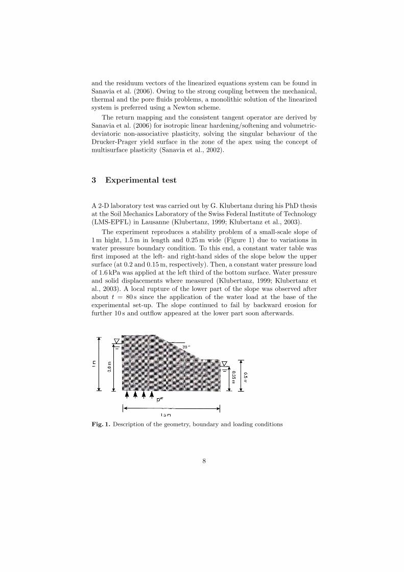
The experiment reproduces a stability problem of a small-scale slope of1m hight, 1.5m in length and 0.25m wide (Figure 1) due to variations inwater pressure boundary condition. To this end, a constant water table wasfirst imposed at the left- and right-hand sides of the slope below the uppersurface (at 0.2 and 0.15 m, respectively). Then, a constant water pressure loadof 1.6 kPa was applied at the left third of the bottom surface. Water pressureand solid displacements where measured (Klubertanz, 1999; Klubertanz etal., 2003). A local rupture of the lower part of the slope was observed afterabout t = 80 s since the application of the water load at the base of theexperimental set-up. The slope continued to fail by backward erosion forfurther 10 s and outflow appeared at the lower part soon afterwards.
Fig. 1. Description of the geometry, boundary and loading conditions
8
4 Numerical Results
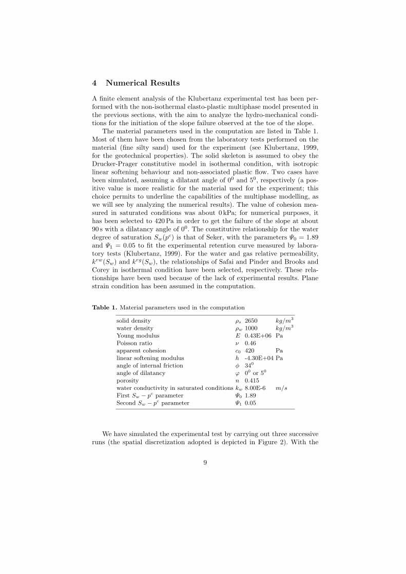
A finite element analysis of the Klubertanz experimental test has been per-formed with the non-isothermal elasto-plastic multiphase model presented inthe previous sections, with the aim to analyze the hydro-mechanical condi-tions for the initiation of the slope failure observed at the toe of the slope.
The material parameters used in the computation are listed in Table 1.Most of them have been chosen from the laboratory tests performed on thematerial (fine silty sand) used for the experiment (see Klubertanz, 1999,for the geotechnical properties). The solid skeleton is assumed to obey theDrucker-Prager constitutive model in isothermal condition, with isotropiclinear softening behaviour and non-associated plastic flow. Two cases havebeen simulated, assuming a dilatant angle of 00 and 50, respectively (a pos-itive value is more realistic for the material used for the experiment; thischoice permits to underline the capabilities of the multiphase modelling, aswe will see by analyzing the numerical results). The value of cohesion mea-sured in saturated conditions was about 0 kPa; for numerical purposes, ithas been selected to 420Pa in order to get the failure of the slope at about90 s with a dilatancy angle of 00. The constitutive relationship for the waterdegree of saturation Sw(pc) is that of Seker, with the parameters Ψ0 = 1.89and Ψ1 = 0.05 to fit the experimental retention curve measured by labora-tory tests (Klubertanz, 1999). For the water and gas relative permeability,krw(Sw) and krg(Sw), the relationships of Safai and Pinder and Brooks andCorey in isothermal condition have been selected, respectively. These rela-tionships have been used because of the lack of experimental results. Planestrain condition has been assumed in the computation.
Table 1. Material parameters used in the computation
solid density ρs 2650 kg/m3
water density ρw 1000 kg/m3
Young modulus E 0.43E+06 PaPoisson ratio ν 0.46apparent cohesion c0 420 Palinear softening modulus h -4.30E+04 Paangle of internal friction φ 340
angle of dilatancy ϕ 00 or 50
porosity n 0.415water conductivity in saturated conditions kw 8.00E-6 m/sFirst Sw − pc parameter Ψ0 1.89Second Sw − pc parameter Ψ1 0.05
We have simulated the experimental test by carrying out three successiveruns (the spatial discretization adopted is depicted in Figure 2). With the
9
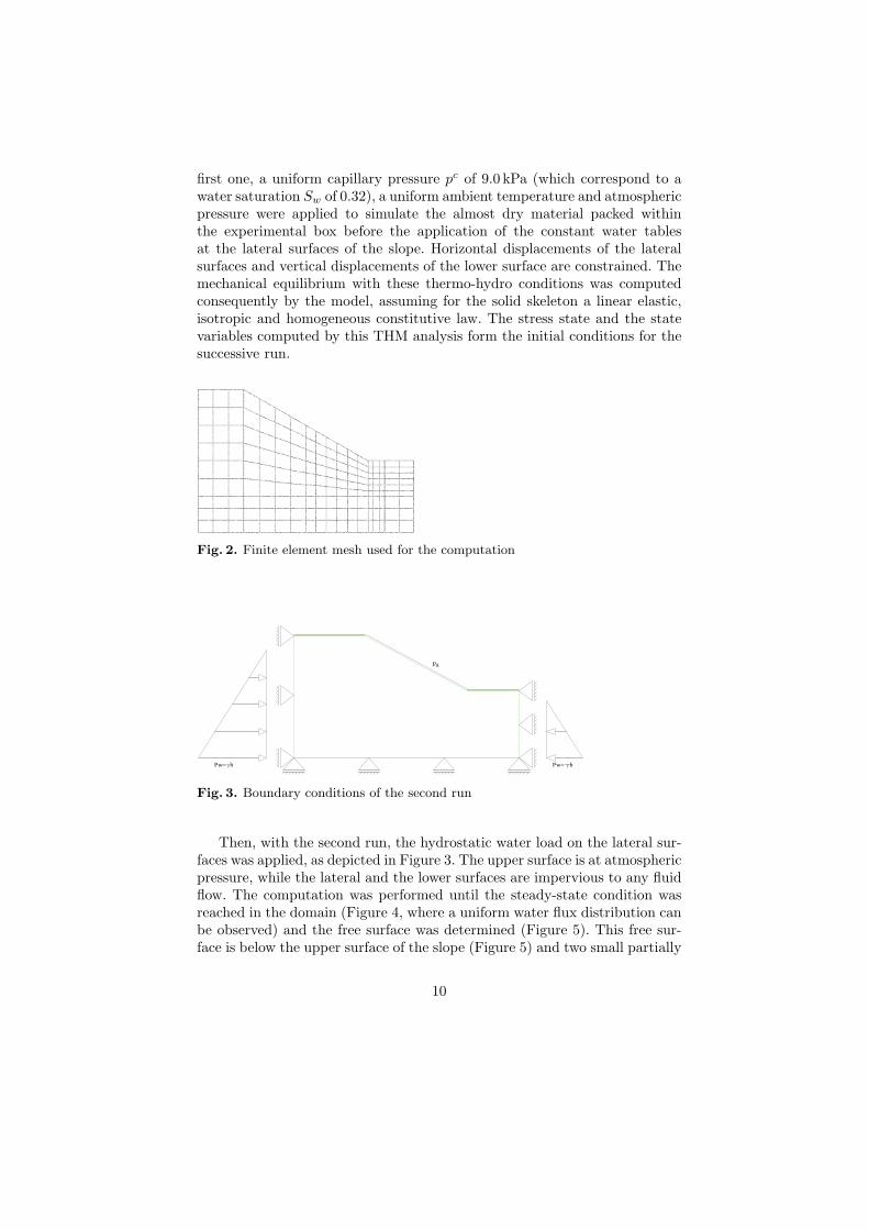
first one, a uniform capillary pressure pc of 9.0 kPa (which correspond to awater saturation Sw of 0.32), a uniform ambient temperature and atmosphericpressure were applied to simulate the almost dry material packed withinthe experimental box before the application of the constant water tablesat the lateral surfaces of the slope. Horizontal displacements of the lateralsurfaces and vertical displacements of the lower surface are constrained. Themechanical equilibrium with these thermo-hydro conditions was computedconsequently by the model, assuming for the solid skeleton a linear elastic,isotropic and homogeneous constitutive law. The stress state and the statevariables computed by this THM analysis form the initial conditions for thesuccessive run.
Fig. 2. Finite element mesh used for the computation
Pw h
Pg
Pw h
Fig. 3. Boundary conditions of the second run
Then, with the second run, the hydrostatic water load on the lateral sur-faces was applied, as depicted in Figure 3. The upper surface is at atmosphericpressure, while the lateral and the lower surfaces are impervious to any fluidflow. The computation was performed until the steady-state condition wasreached in the domain (Figure 4, where a uniform water flux distribution canbe observed) and the free surface was determined (Figure 5). This free sur-face is below the upper surface of the slope (Figure 5) and two small partially
10
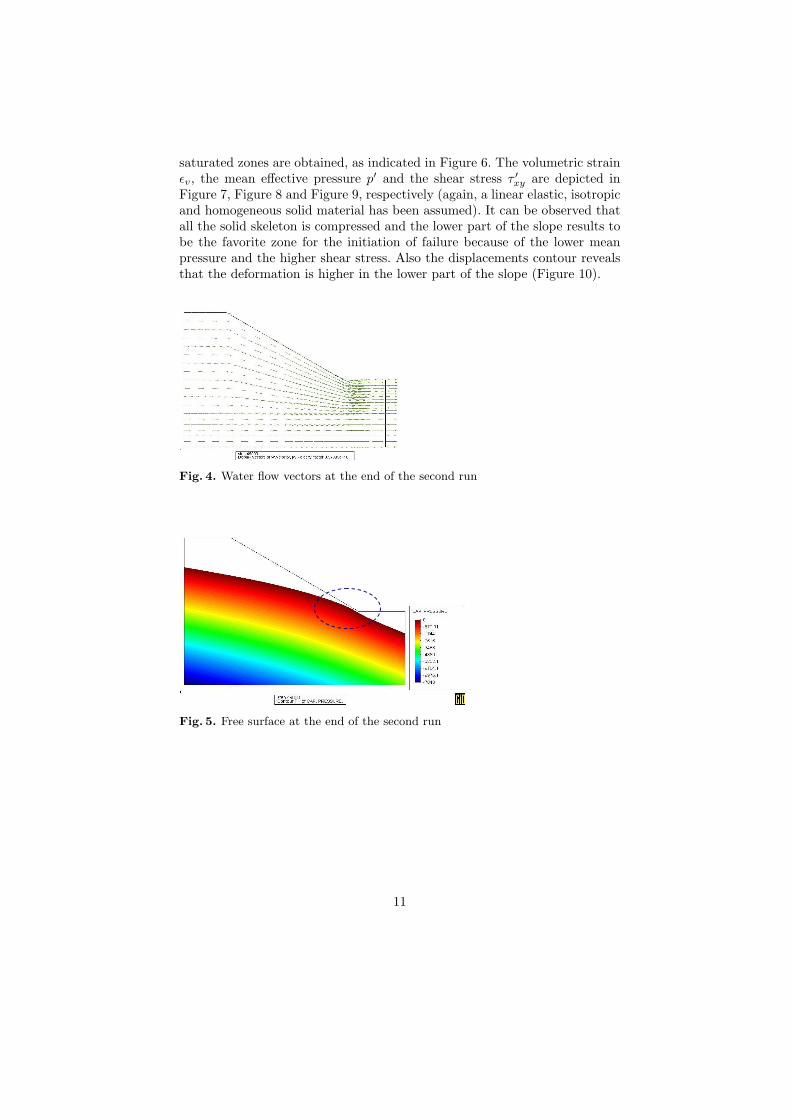
saturated zones are obtained, as indicated in Figure 6. The volumetric strainεv, the mean effective pressure p′ and the shear stress τ ′xy are depicted inFigure 7, Figure 8 and Figure 9, respectively (again, a linear elastic, isotropicand homogeneous solid material has been assumed). It can be observed thatall the solid skeleton is compressed and the lower part of the slope results tobe the favorite zone for the initiation of failure because of the lower meanpressure and the higher shear stress. Also the displacements contour revealsthat the deformation is higher in the lower part of the slope (Figure 10).
Fig. 4. Water flow vectors at the end of the second run
Fig. 5. Free surface at the end of the second run
11
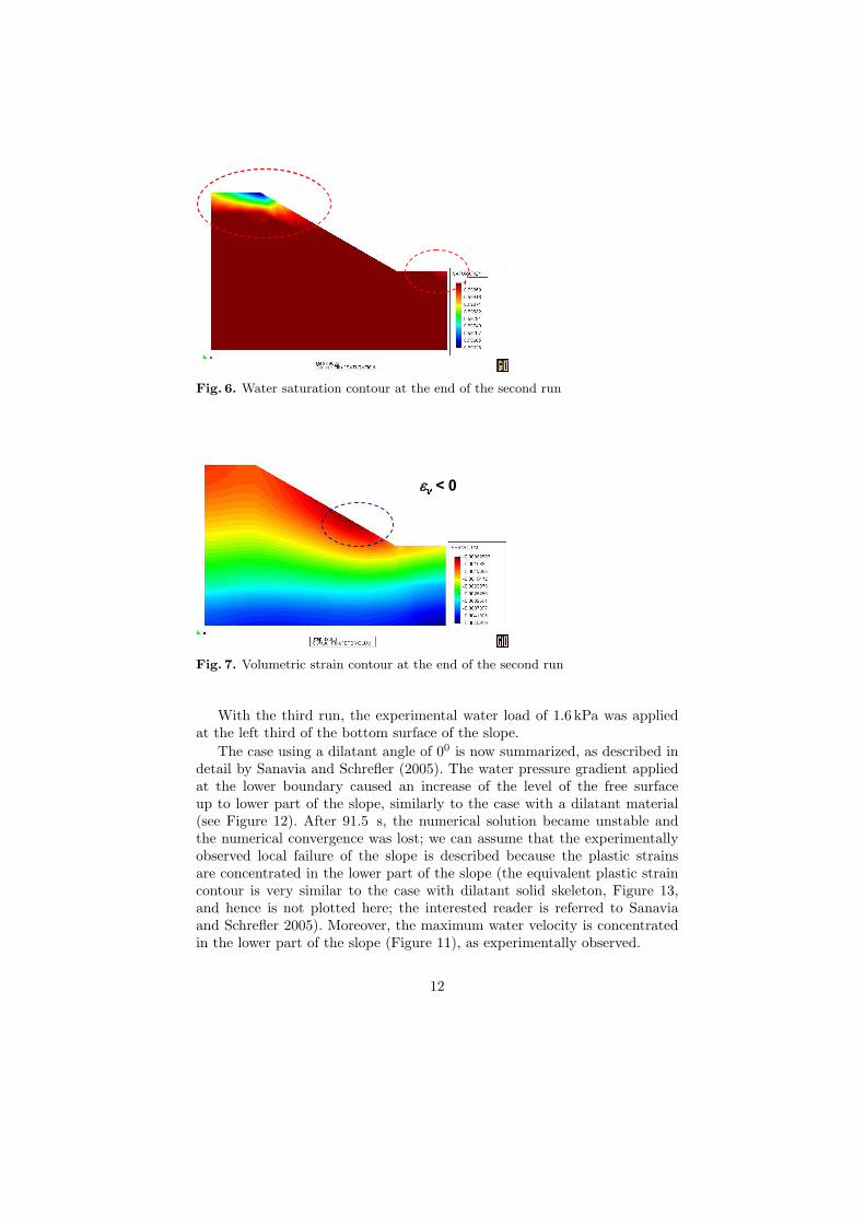
Fig. 6. Water saturation contour at the end of the second run
Fig. 7. Volumetric strain contour at the end of the second run
With the third run, the experimental water load of 1.6 kPa was appliedat the left third of the bottom surface of the slope.
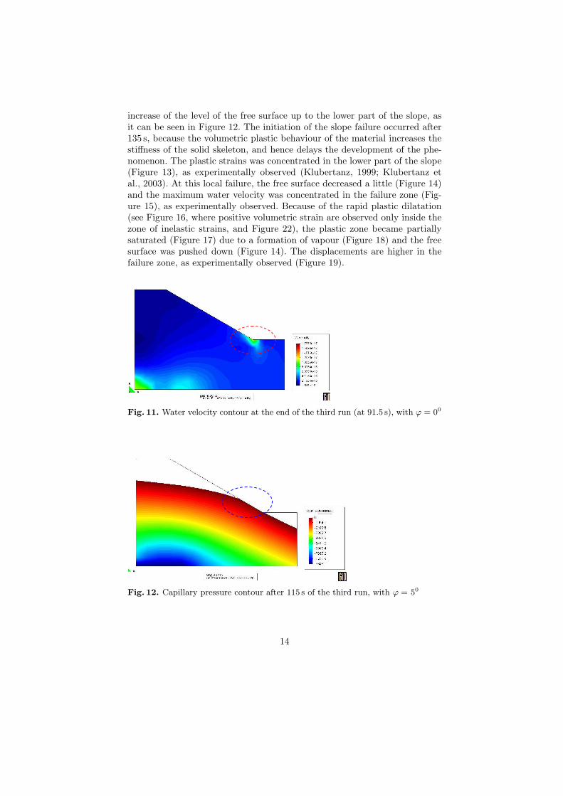
The case using a dilatant angle of 00 is now summarized, as described indetail by Sanavia and Schrefler (2005). The water pressure gradient appliedat the lower boundary caused an increase of the level of the free surfaceup to lower part of the slope, similarly to the case with a dilatant material(see Figure 12). After 91.5 s, the numerical solution became unstable andthe numerical convergence was lost; we can assume that the experimentallyobserved local failure of the slope is described because the plastic strainsare concentrated in the lower part of the slope (the equivalent plastic straincontour is very similar to the case with dilatant solid skeleton, Figure 13,and hence is not plotted here; the interested reader is referred to Sanaviaand Schrefler 2005). Moreover, the maximum water velocity is concentratedin the lower part of the slope (Figure 11), as experimentally observed.
12

Fig. 8. Mean effective pressure p′ contour at the end of the second run
Fig. 9. Shear stress τ ′xy contour at the end of the second run
Fig. 10. Displacements contour at the end of the second run
The simulation which assume a slightly dilatant material (ϕ = 50) ismore interesting because it reveals the capability of the multiphase approachto deal with such kind of problems.Again, the water pressure gradient applied at the lower boundary caused an
13
increase of the level of the free surface up to the lower part of the slope, asit can be seen in Figure 12. The initiation of the slope failure occurred after135 s, because the volumetric plastic behaviour of the material increases thestiffness of the solid skeleton, and hence delays the development of the phe-nomenon. The plastic strains was concentrated in the lower part of the slope(Figure 13), as experimentally observed (Klubertanz, 1999; Klubertanz etal., 2003). At this local failure, the free surface decreased a little (Figure 14)and the maximum water velocity was concentrated in the failure zone (Fig-ure 15), as experimentally observed. Because of the rapid plastic dilatation(see Figure 16, where positive volumetric strain are observed only inside thezone of inelastic strains, and Figure 22), the plastic zone became partiallysaturated (Figure 17) due to a formation of vapour (Figure 18) and the freesurface was pushed down (Figure 14). The displacements are higher in thefailure zone, as experimentally observed (Figure 19).
Fig. 11. Water velocity contour at the end of the third run (at 91.5 s), with ϕ = 00
Fig. 12. Capillary pressure contour after 115 s of the third run, with ϕ = 50
14
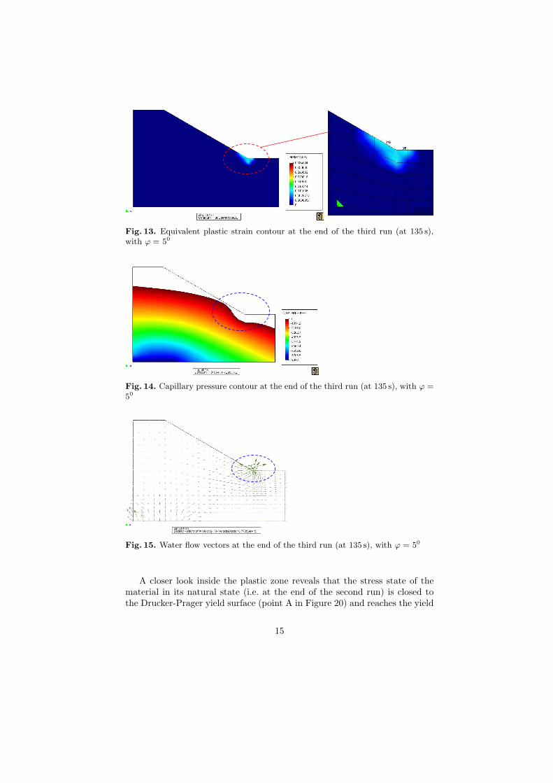
Fig. 13. Equivalent plastic strain contour at the end of the third run (at 135 s),with ϕ = 50
Fig. 14. Capillary pressure contour at the end of the third run (at 135 s), with ϕ =50
Fig. 15. Water flow vectors at the end of the third run (at 135 s), with ϕ = 50
A closer look inside the plastic zone reveals that the stress state of thematerial in its natural state (i.e. at the end of the second run) is closed tothe Drucker-Prager yield surface (point A in Figure 20) and reaches the yield
15
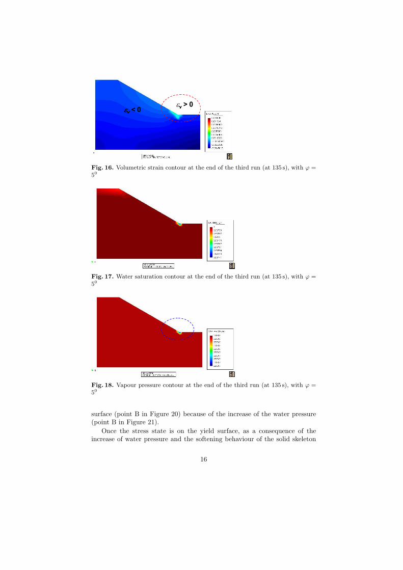
Fig. 16. Volumetric strain contour at the end of the third run (at 135 s), with ϕ =50
Fig. 17. Water saturation contour at the end of the third run (at 135 s), with ϕ =50
Fig. 18. Vapour pressure contour at the end of the third run (at 135 s), with ϕ =50
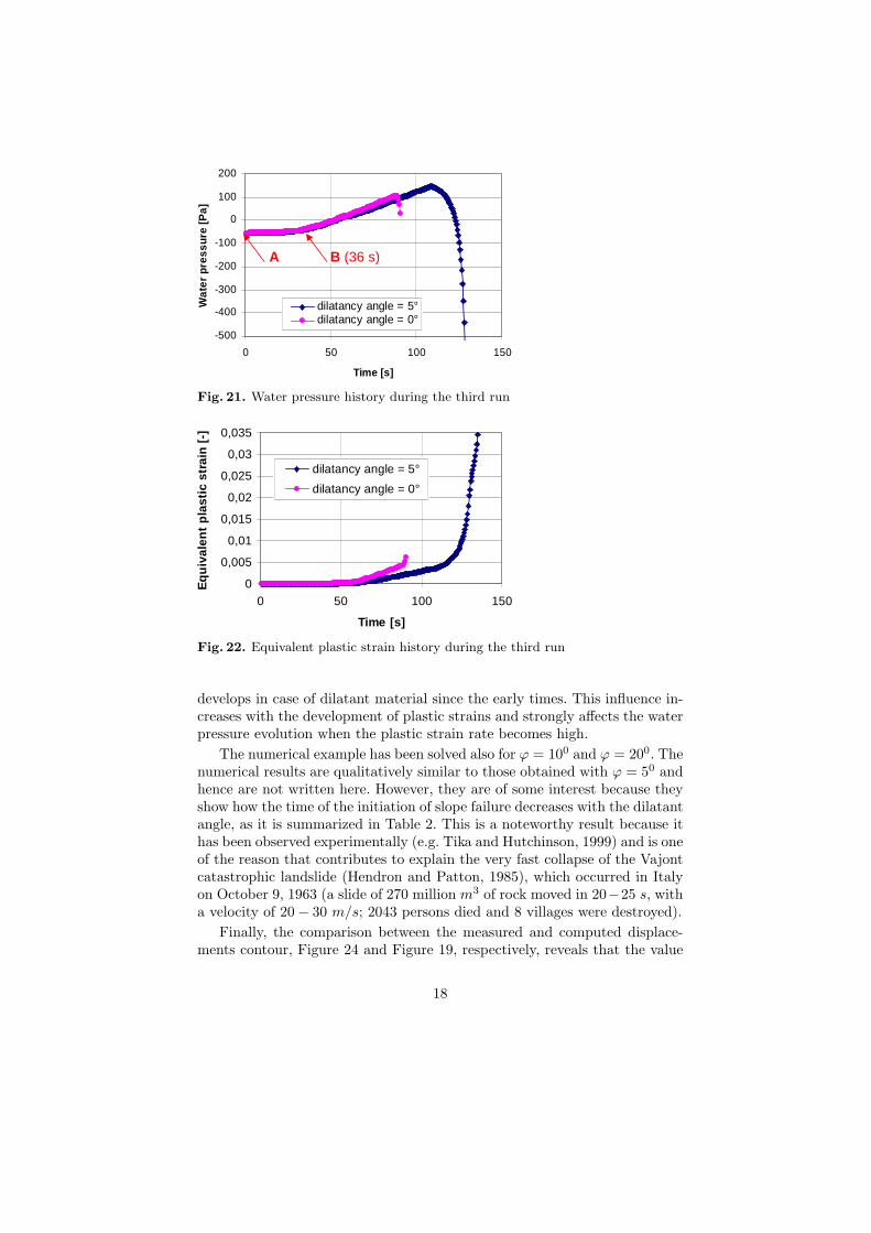
surface (point B in Figure 20) because of the increase of the water pressure(point B in Figure 21).
Once the stress state is on the yield surface, as a consequence of theincrease of water pressure and the softening behaviour of the solid skeleton
16
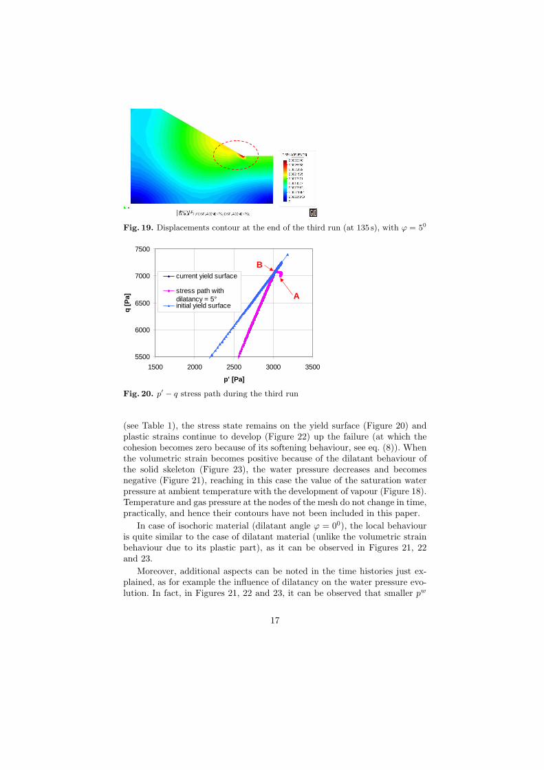
Fig. 19. Displacements contour at the end of the third run (at 135 s), with ϕ = 50
5500
6000
6500
7000
7500
1500 2000 2500 3000 3500
p' [Pa]
q [P
a]
current yield surface
stress path withdilatancy = 5°initial yield surface
A
B
5500
6000
6500
7000
7500
1500 2000 2500 3000 3500
p' [Pa]
q [P
a]
current yield surface
stress path withdilatancy = 5°initial yield surface
A
B
Fig. 20. p′ − q stress path during the third run
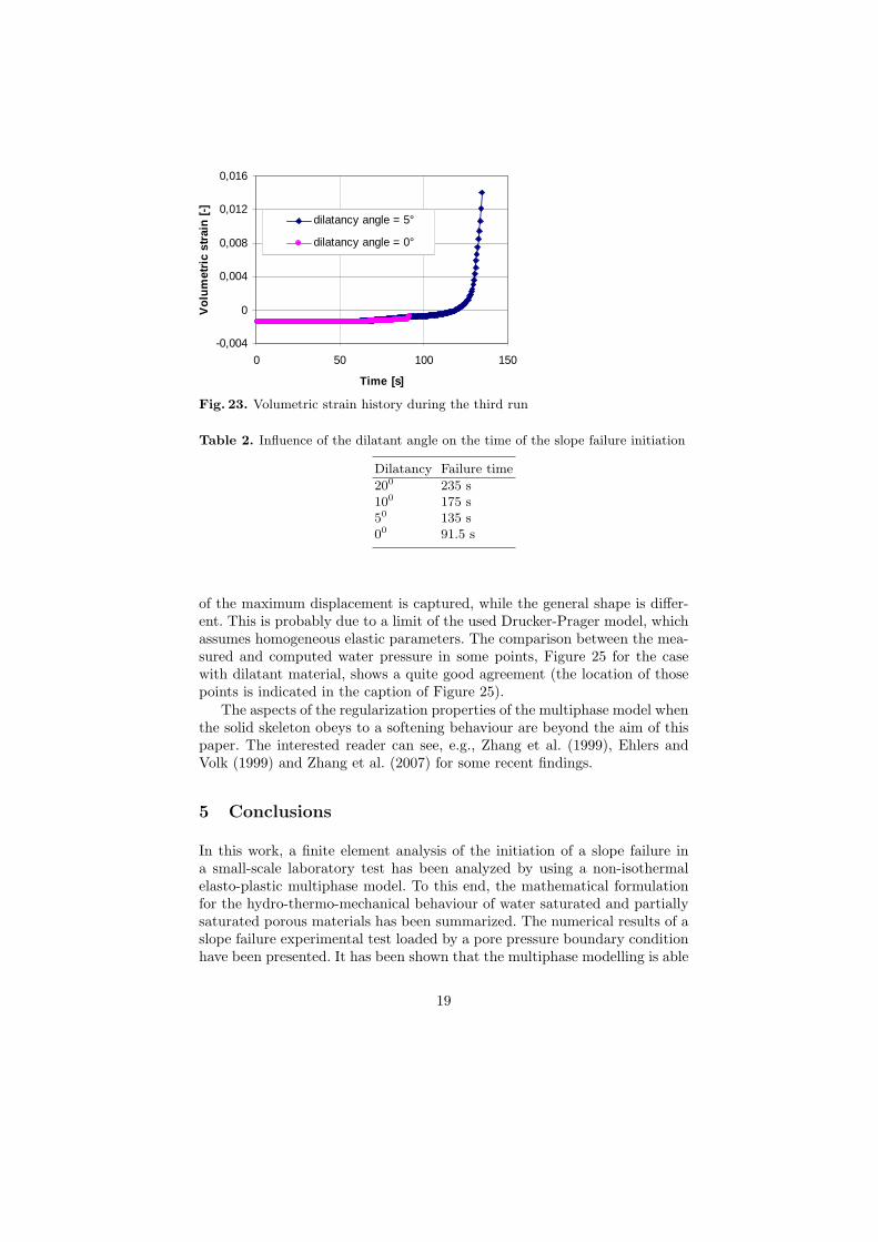
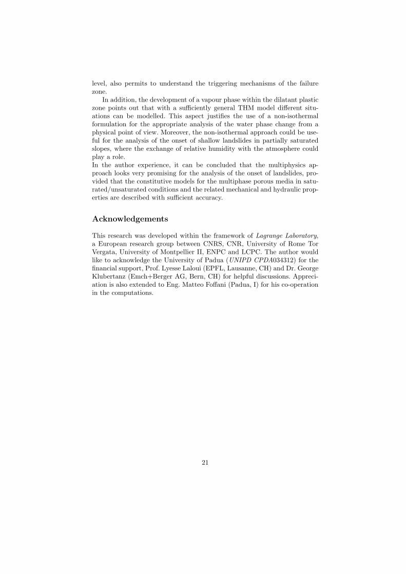
(see Table 1), the stress state remains on the yield surface (Figure 20) andplastic strains continue to develop (Figure 22) up the failure (at which thecohesion becomes zero because of its softening behaviour, see eq. (8)). Whenthe volumetric strain becomes positive because of the dilatant behaviour ofthe solid skeleton (Figure 23), the water pressure decreases and becomesnegative (Figure 21), reaching in this case the value of the saturation waterpressure at ambient temperature with the development of vapour (Figure 18).Temperature and gas pressure at the nodes of the mesh do not change in time,practically, and hence their contours have not been included in this paper.
In case of isochoric material (dilatant angle ϕ = 00), the local behaviouris quite similar to the case of dilatant material (unlike the volumetric strainbehaviour due to its plastic part), as it can be observed in Figures 21, 22and 23.
Moreover, additional aspects can be noted in the time histories just ex-plained, as for example the influence of dilatancy on the water pressure evo-lution. In fact, in Figures 21, 22 and 23, it can be observed that smaller pw
17
-500
-400
-300
-200
-100
0
100
200
0 50 100 150
Time [s]
Wat
er p
ress
ure
[Pa]
dilatancy angle = 5°dilatancy angle = 0°
A B (36 s)
Fig. 21. Water pressure history during the third run
0
0,005
0,01
0,015
0,02
0,025
0,03
0,035
0 50 100 150
Time [s]
Eq
uiv
alen
t p
last
ic s
trai
n [
-]
dilatancy angle = 5°
dilatancy angle = 0°
Fig. 22. Equivalent plastic strain history during the third run
develops in case of dilatant material since the early times. This influence in-creases with the development of plastic strains and strongly affects the waterpressure evolution when the plastic strain rate becomes high.
The numerical example has been solved also for ϕ = 100 and ϕ = 200. Thenumerical results are qualitatively similar to those obtained with ϕ = 50 andhence are not written here. However, they are of some interest because theyshow how the time of the initiation of slope failure decreases with the dilatantangle, as it is summarized in Table 2. This is a noteworthy result because ithas been observed experimentally (e.g. Tika and Hutchinson, 1999) and is oneof the reason that contributes to explain the very fast collapse of the Vajontcatastrophic landslide (Hendron and Patton, 1985), which occurred in Italyon October 9, 1963 (a slide of 270 million m3 of rock moved in 20−25 s, witha velocity of 20− 30 m/s; 2043 persons died and 8 villages were destroyed).
Finally, the comparison between the measured and computed displace-ments contour, Figure 24 and Figure 19, respectively, reveals that the value
18
-0,004
0
0,004
0,008
0,012
0,016
0 50 100 150
Time [s]
Vo
lum
etri
c st
rain
[-]
dilatancy angle = 5°
dilatancy angle = 0°
Fig. 23. Volumetric strain history during the third run
Table 2. Influence of the dilatant angle on the time of the slope failure initiation
Dilatancy Failure time
200 235 s100 175 s50 135 s00 91.5 s
of the maximum displacement is captured, while the general shape is differ-ent. This is probably due to a limit of the used Drucker-Prager model, whichassumes homogeneous elastic parameters. The comparison between the mea-sured and computed water pressure in some points, Figure 25 for the casewith dilatant material, shows a quite good agreement (the location of thosepoints is indicated in the caption of Figure 25).
The aspects of the regularization properties of the multiphase model whenthe solid skeleton obeys to a softening behaviour are beyond the aim of thispaper. The interested reader can see, e.g., Zhang et al. (1999), Ehlers andVolk (1999) and Zhang et al. (2007) for some recent findings.
5 Conclusions
In this work, a finite element analysis of the initiation of a slope failure ina small-scale laboratory test has been analyzed by using a non-isothermalelasto-plastic multiphase model. To this end, the mathematical formulationfor the hydro-thermo-mechanical behaviour of water saturated and partiallysaturated porous materials has been summarized. The numerical results of aslope failure experimental test loaded by a pore pressure boundary conditionhave been presented. It has been shown that the multiphase modelling is able
19

Fig. 24. Experimental displacements contour (Klubertanz, 1999)
-2000
-1000
0
1000
2000
3000
4000
5000
0 10 20 30 40 50 60 70 80 90 100
time [s]
wat
er p
ress
ure
[Pa]
experimental value in Pt2
node 97 - Pt2
experimental value in Pt3
node 69 - Pt3
experimental value in Pt4
node 113 - Pt4
experimental value in Pt5
node 243 - Pt5
Fig. 25. Comparison between experimental and numerical water pressures in thepoints with coordinates: Pt2 (0.40, 0.40), Pt3 (0.40, 0.60), Pt4 (0.60, 0.60), Pt5(0.90, 0.40)
to capture the main experimental observations at global level such as the localfailure zone at the onset of slope failure and the outflow appeared in that zone.This modelling approach, by the analysis of the THM computations at local
20
level, also permits to understand the triggering mechanisms of the failurezone.
In addition, the development of a vapour phase within the dilatant plasticzone points out that with a sufficiently general THM model different situ-ations can be modelled. This aspect justifies the use of a non-isothermalformulation for the appropriate analysis of the water phase change from aphysical point of view. Moreover, the non-isothermal approach could be use-ful for the analysis of the onset of shallow landslides in partially saturatedslopes, where the exchange of relative humidity with the atmosphere couldplay a role.In the author experience, it can be concluded that the multiphysics ap-proach looks very promising for the analysis of the onset of landslides, pro-vided that the constitutive models for the multiphase porous media in satu-rated/unsaturated conditions and the related mechanical and hydraulic prop-erties are described with sufficient accuracy.
Acknowledgements
This research was developed within the framework of Lagrange Laboratory,a European research group between CNRS, CNR, University of Rome TorVergata, University of Montpellier II, ENPC and LCPC. The author wouldlike to acknowledge the University of Padua (UNIPD CPDA034312) for thefinancial support, Prof. Lyesse Laloui (EPFL, Lausanne, CH) and Dr. GeorgeKlubertanz (Emch+Berger AG, Bern, CH) for helpful discussions. Appreci-ation is also extended to Eng. Matteo Foffani (Padua, I) for his co-operationin the computations.
21

Bibliography
Alonso, E.E., Gens, A. and Josa, A. (1990), ”A constitutive model for par-tially saturated soils”, Geotechnique, Vol. 40, pp. 403–430.
Bertrand, F. and Laloui L. (2008), ”ACMEG-TS: a constitutive model forunsaturated soils under non-isothermal conditions”, Int. J. Numer. Anal.Meth. Geomech., doi:10.1002/nag.712.
Bolzon, G., Schrefler, B.A. and Zienkiewicz O.C. (1996), ”Elastoplastic soilconstitutive laws generalized to partially saturated states”, Geotechnique,Vol. 46, pp. 279–289.
Bolton, M.D., Take, W.A., Wong, P.C.P. and Yeung F.J. (2003), ”Mecha-nisms of failure in fill slopes after intense rainfall”, Keynote Paper, Int.Conf. on Slope Engineering, Hong Kong, China, pp.125.
Borja, R.J. (2004), ”Cam-clay plasticity. Part V: A mathematical frameworkfor three-phase deformation and strain localisation analyses of partiallysaturated porous media”, Comp. Methods Appl. Mech. Engrg., Vol. 193,pp. 5301–5338.
Cascini, L., Sorbino, G. and Cuomo S. (2005), ”Flow-like mass movementsin pyroclastic soils: remarks on the modeling of triggering mechanisms”,Rivista Italiana di Geotecnica, Vol. 4, pp. 11–31.
Dikau, R., Brundsen, D., Schrott, L. and Ibses M.L. (1996), Landslide Recog-nition, John Wiley & Sons.
Ehlers, W. and Volk, W., (1999), ”Localization Phenomena in Liquid-Saturated and Empty Porous Solids”, Transport in Porous Media, Vol.34, pp. 159–177.
Ehlers, W., Graf, T. and Ammann M. (2004), ”Deformation and localizationanalysis in partially saturated soil”, Comp. Methods Appl. Mech. Engrg.,Vol. 193, pp. 2885–2910.
Fernandez Merodo, J.A., Pastor, M.,Mira, P., Tonni L., Herreros, M.I., Gon-zalez E. and Tamagnini R. (2004) ”Modelling of diffuse failure mechanismsof catastrophic landslides”, Comp. Methods Appl. Mech. Engrg., Vol. 193,pp.2911–2939.
Gawin, D., Baggio, P. and Schrefler B.A. (1995), ”Coupled heat, water andgas flow in deformable porous media”, Int. J. Num. methods in Fluids, Vol.20 No.7, pp. 967–987.
Gray, W.G. and Hassanizadeh, M. (1991), ”Unsaturated Flow Theory in-cluding Interfacial Phenomena”, Water Resources Res., Vol. 27 No.8, pp.1855–1863.
Gray, W.G. and Schrefler, B.A. (2001), ”Thermodynamic approach to effec-tive stress in partially saturated porous media”, Eur. J. Mech. A/Solids,Vol. 20, pp. 521–538.

Hassanizadeh, M. and Gray, W.G. (1979a), ”General Conservation Equationsfor Multi-phase System: 1. Averaging technique”, Adv. Water Res, Vol. 2,pp. 131–144.
Hassanizadeh, M. and Gray, W.G. (1979b), ”General Conservation Equa-tions for Multi-Phase System: 2. Mass, Momenta, Energy and EntropyEquations”, Adv. Water Res, Vol. 2, pp. 191–201.
Hassanizadeh, M. and Gray, W.G. (1980), ”General Conservation Equationsfor Multi-Phase System: 3. Constitutive Theory for Porous Media Flow”,Adv. Water Res, Vol. 3, pp. 25–40.
Hendron, A.J. and Patton, F.D. (1985), The Vaiont slide, a geotechnical anal-ysis based on new geologic observations of the failure surface, TechnicalReport GL-85-5. Washington DC, Department of the Army US Corps ofEngineers vol. I.
Klubertanz G. (1999), Zur hydromechanischen Kopplung in dreiphasigenporsen Medien, Ph.D. Thesis n.2027, Lausanne: Ecole Polytechnique Fdralede Lausanne.
Klubertanz, G., Bouchelaghem, F., Laloui, L. and Vulliet L. (2003), ”Miscibleand immiscible multiphase flow in deformable porous media”, Mathemati-cal and Computer Modelling, Vol. 37, pp. 571–582.
Lewis, R.W. and Schrefler B.A. (1987), The Finite Element Method in theDeformation and Consolidation of Porous Media (1st edn). Wiley & Sons,Chichester.
Lewis, R.W. and Schrefler B.A. (1998), The Finite Element Method in theStatic and Dynamic Deformation and Consolidation of Porous Media, JohnWiley & Sons, Chichester, UK.
Nuth, M. and Laloui, L. (2008), ”Effective stress concept in unsaturated soils:Clarification and validation of a unified approach”, Int. J. Numer. Anal.Meth. Geomech., doi:10.1002/nag.645.
Pastor, M., Fernandez Merodo, J.A., Gonzalez, E., Mira, P., Li, T. and LiuX. (2004a), ”Modelling of Landslides: (I) Failure Mechanisms, in: Darve F.and Vardoulakis I. (Ed.) Degradations and Instabilities in Geomaterials,CISM Courses and Lectures No. 461, Springer-Verlag.
Pastor, M., Quecedo, M., Gonzalez, E., Herreros, M.I., Fernandez Merodo,J.A. and Mira P. (2004b), ”Modelling of Landslides: (II) Propagation”,in: Darve F. and Vardoulakis I. (Ed.), Degradations and Instabilities inGeomaterials, CISM Courses and Lectures No. 461, Springer-Verlag.
Pastor, M., Quecedo, M., Gonzalez, E., Herreros, M.I., Fernandez Merodo,J.A. and Mira P. (2004c), ”Numerical modelling of the propagation of fastlandslides using the finite element method”, Int. J. Numer. Meth. Engrg,Vol. 59, pp. 755–794.
Sanavia, L. and Schrefler, B.A. (2005), ”Finite element analysis of the initia-tion of landslides with a multiphase model”, Proceedings, 3rd Biot Confer-ence on Poromechanics, Abousleiman, Y., Cheng, A.H.-D., and Ulm, F.-J.(Ed.), Poromechanics III-Biot Centennial (1905-2005), A.A. Balkema, Lei-don/London/New York/Philadelphia/Singapore, pp. 397–402.
24
Sanavia, L., Schrefler, B.A. and Steinmann, P. (2002), ”A formulation for anunsaturated porous medium undergoing large inelastic strains”, Computa-tional Mechanics, Vol. 28, pp. 137–151.
Sanavia, L., Pesavento, F. and Schrefler B.A. (2006), ”Finite element anal-ysis of non-isothermal multiphase geomaterials with application to strainlocalisation simulation”, Computational Mechanics, Vol. 37, pp. 331–348.
Schrefler, B.A. (1984), The Finite Element Method in Soil Consolidation(with applications to Surface Subsidence), Ph.D. Thesis, University Col-lege of Swansea, C/Ph/76/84, Swansea, UK.
Schrefler, B.A. (2002), ”Mechanics and Thermodynamics of Saturated-Unsaturated Porous Materials and Quantitative Solutions”, Applied Me-chanics Review, Vol. 55 No.4, pp. 351–388.
Schrefler, B.A., Simoni, L., Li, X. and Zienkiewicz, O.C. (1990), ”Mechanicsof partially saturated porous media”, in Desai C.S. and Gioda G. (Ed.),Numerical Methods and Constitutive Modelling in Geomechanics, CISMCourses and Lectures No 311, Springer-Verlag, pp. 169–209.
Tacher, L., Bonnard, C., Laloui, L. and Parriaux A. (2005), ”Modelling thebehaviour of a large landslide with respect to hydrogeological and geome-chanical parameter hererogeneity”, Landslides, Vol. 2, pp. 3–14.
Tika, T.E. and Hutchinson, J.N. (1999), ”Ring shear testes on soil from theVaiont landslide slip surface”, Geotechnique, Vol. 49 No.1, pp.59–74.
Zhang, H.W., Sanavia, L. and Schrefler, B.A. (1999), ”An internal lengthscale in dynamic strain localisation of multiphase porous media”, Mechan-ics of Cohesive-Frictional Materials, Vol. 4, pp. 443–460.
Zhang, H.W., Sanavia, L. and Schrefler B.A. (2000), ”Numerical analysis ofdynamic strain localisation in initially water saturated dense sand with amodified generalised plasticity model”, Computers and Structures, Vol. 79,pp. 441–459.
Zhang, H.W., Qin, J.M., Sanavia, L. and Schrefler B.A. (2007), ”Some the-oretical aspects of strain localization analysis of multiphase porous mediawith regularized constitutive models”, Mechanics of Advanced Materialsand Structures, Vol. 14 No.2, pp. 107–130.
Zienkiewicz, O.C., Chan, A., Pastor, M., Schrefler, B.A. and Shiomi T.(1999), Computational Geomechanics with special Reference to EarthquakeEngineering, John Wiley & Sons, Chichester.
25