Embed Size (px)
Citation preview
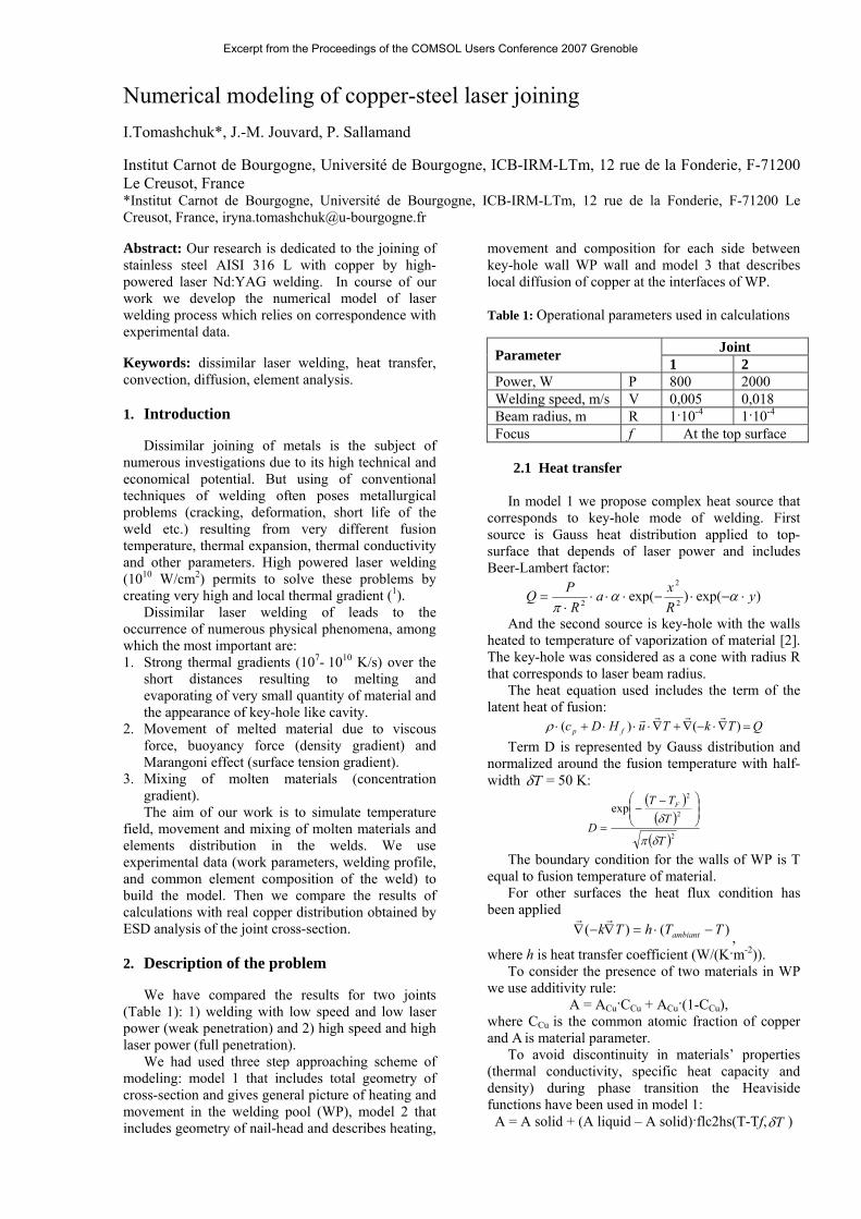
Numerical modeling of copper-steel laser joining ITomashchuk J-M Jouvard P Sallamand
Institut Carnot de Bourgogne Universiteacute de Bourgogne ICB-IRM-LTm 12 rue de la Fonderie F-71200 Le Creusot France Institut Carnot de Bourgogne Universiteacute de Bourgogne ICB-IRM-LTm 12 rue de la Fonderie F-71200 Le Creusot France irynatomashchuku-bourgognefr
Abstract Our research is dedicated to the joining of stainless steel AISI 316 L with copper by high-powered laser NdYAG welding In course of our work we develop the numerical model of laser welding process which relies on correspondence with experimental data
Keywords dissimilar laser welding heat transfer convection diffusion element analysis 1 Introduction
Dissimilar joining of metals is the subject of numerous investigations due to its high technical and economical potential But using of conventional techniques of welding often poses metallurgical problems (cracking deformation short life of the weld etc) resulting from very different fusion temperature thermal expansion thermal conductivity and other parameters High powered laser welding (1010 Wcm2) permits to solve these problems by creating very high and local thermal gradient (1)
Dissimilar laser welding of leads to the occurrence of numerous physical phenomena among which the most important are 1 Strong thermal gradients (107- 1010 Ks) over the
short distances resulting to melting and evaporating of very small quantity of material and the appearance of key-hole like cavity
2 Movement of melted material due to viscous force buoyancy force (density gradient) and Marangoni effect (surface tension gradient)
3 Mixing of molten materials (concentration gradient) The aim of our work is to simulate temperature
field movement and mixing of molten materials and elements distribution in the welds We use experimental data (work parameters welding profile and common element composition of the weld) to build the model Then we compare the results of calculations with real copper distribution obtained by ESD analysis of the joint cross-section
2 Description of the problem
We have compared the results for two joints (Table 1) 1) welding with low speed and low laser power (weak penetration) and 2) high speed and high laser power (full penetration)
We had used three step approaching scheme of modeling model 1 that includes total geometry of cross-section and gives general picture of heating and movement in the welding pool (WP) model 2 that includes geometry of nail-head and describes heating
movement and composition for each side between key-hole wall WP wall and model 3 that describes local diffusion of copper at the interfaces of WP
Table 1 Operational parameters used in calculations
Joint Parameter 1 2 Power W P 800 2000 Welding speed ms V 0005 0018 Beam radius m R 110-4 110-4
Focus f At the top surface 21 Heat transfer
In model 1 we propose complex heat source that corresponds to key-hole mode of welding First source is Gauss heat distribution applied to top-surface that depends of laser power and includes Beer-Lambert factor
)exp()exp( 2
2
2 yRxa
RPQ sdotminussdotminussdotsdotsdotsdot
= ααπ
And the second source is key-hole with the walls heated to temperature of vaporization of material [2] The key-hole was considered as a cone with radius R that corresponds to laser beam radius
The heat equation used includes the term of the latent heat of fusion
QTkTuHDc fp =nablasdotminusnabla+nablasdotsdotsdot+sdot )()(rrrrρ
Term D is represented by Gauss distribution and normalized around the fusion temperature with half-width Tδ = 50 K
( )( )( )2
2
2
exp
T
TTT
D
F
δπ
δ ⎟⎟⎠
⎞⎜⎜⎝
⎛ minusminus
=
The boundary condition for the walls of WP is T equal to fusion temperature of material
For other surfaces the heat flux condition has been applied
)()( TThTk ambiant minussdot=nablaminusnablarr
where h is heat transfer coefficient (W(Km-2))
To consider the presence of two materials in WP we use additivity rule
A = ACuCCu + ACu(1-CCu) where CCu is the common atomic fraction of copper and A is material parameter
To avoid discontinuity in materialsrsquo properties (thermal conductivity specific heat capacity and density) during phase transition the Heaviside functions have been used in model 1
A = A solid + (A liquid ndash A solid)flc2hs(T-Tf Tδ )
Excerpt from the Proceedings of the COMSOL Users Conference 2007 Grenoble
Model 2 present top part of WP and has been made to calculate precisely velocity and element distribution The molten material has a temperature TmeltingltTltTvaporization so we consider condition of Tvaporization for the wall of key-hole and T melting for liquidsolid surface and heat flux for top surface Inferior part of nail-head has thermal isolation condition Model 2 presents only liquid state and material parameters has been takes as constants at additivity rule
Model 3 presents dissolution of copper (melting at 1385 K) during the contact with molten steel (1720 K) at the copper side of the weld
The materialsrsquo properties are assumed in Table 3 22 Hydrodynamic equations
Modeling of the flow in the WP is based on the resolution of Navier-Stokes equations
( )( )( ) 0
)()(
=sdotsdotnabla
+nabla+nablasdot+minussdotnabla=sdotnablasdotsdot
u
FuuuTu T
rr
rrrrrr
ρ
ηρρ
The Boussinesq approximation is used to
represent the buoyancy-driven flow )( maxTTgF minussdotsdotsdot= ρα
The boundary conditions for model 1 and 2 are follows for walls of the key-hole and for metalair interfaces nu = 0 (slip condition) and for walls of WP u =0 (no-slip condition) have been applied The condition of Marangoni convection has been applied to metalair interfaces (using week formulation)
dxdT
dydux sdot=sdot γη
The properties of molten metal have been taken as constants To consider the presence of two materials in WP we use additivity rule
Model 3 does not include liquid flow 23 Element distribution
Coupling of heat transfer convection and diffusion processes permit to simulate elemental distribution in dissimilar welds We do the simplification utilizing copper diffusion coefficient in liquid iron in Fickrsquos law
0)( =nablasdotminusnabla cD
We consider diffusion coefficient as a function of temperature
)exp(0 TREDDsdot
minussdot=
Table 2 Diffusion constants [3]
Constant Cu in Fe Diffusion coefficient m2s D 310-4
Activation energy kJmol E 225
At the model 2 the boundary condition for the wall of key-hole was given as medium copper concentration determined by element analysis Concentration of copper for the walls of WP was
considered as 100 for copper and 0 for steel For the others surfaces the condition of symmetry was applied
At the model 3 we apply the same conditions but we neglect convection at WP interface
3 Numerical approach
31 Mesh-based geometry We use experimental data to create exact profile of
weld cross-section (Figure 1) For model 1 we define two sections of meshing fine meshing (20 microm) for the welding pool and coarse meshing (20 microm) for the rest For model 2 (Figure 2 a) we examine only melting pool so the meshing used is more fine ndash 5 microm For model 3 we use also fine meshing (5 microm) for molted zone and coarser (20 microm) for the solid (Figure 2 b)
Table 3 Physical constants for the materials used in calculations (4)
Material Constant Cu Steel Fusion temperature K
Tf 1356 1720
Evaporation temperature K
Tv 2835 3013
Absorbance coefficient
a 1 30
Extinction coefficient m-1
α 300 300
Latent heat of fusion Jmol
Hf 13103 26105
Density (solid) kgm3
ρs 8700 7980
Density (liquid) kgm3
ρl 7940 7551
Heat capacity (solid) J(kgK)
Cps 385 433
Heat capacity (liquid) J(kgK)
Cpl 350 734
Thermal conductivity (solid) W(mK)
ks 400 8116
Thermal conductivity (liquid) W(mK)
kl 140 1229
Thermal expansion coefficient m(mK)
β 2510-5 2410-5
Surface tension temperature coefficient N(mK)
γ -1710-4 -4310-4
Dynamic viscosity kg(ms)
η 00039 0005
32 Numerical scheme
During continuous welding laser beam creates welding front that moves linearly and recreates the
Excerpt from the Proceedings of the COMSOL Users Conference 2007 Grenoble
similar transversal pattern of welding pool all long the specimen We solve the models that represent such patterns (cross-sections) corresponding to maximum keyhole penetration All the models had been solved with stationary solvers
At the Model 1 velocity distribution in case of Marangoni effect has been calculated by stationary linear solver UMFPACK due to certain convergence problems in nonlinear solver Models 2 and 3 have been solved by stationary nonlinear solver UMFPACK
4 Results and discussions
The major specific feature of dissimilar weld it is
asymmetry in shape and elementary composition that finally determines its mechanical resistance High thermal conductivity and reflectivity of copper lead to formation of welds with only 10-20 vol Cu
Figure 1 Mesh and geometry model 1 joint 1 (top) and 2 (down)
Figure 2 Mesh and geob) model 3
The joints 1 and 2 oheat gradient and givdistribution In both caof the weld convectioneffect (maximum velociis in agreement with tyhorizontal propagation negative temperature co
Big Marangoni number (Table 4) confirms crucial role of thermocapillary effect in formation of WP at the steel side Value of Reynolds number indicates approaching to turbulent regime (105) In case of full penetration we observe second nail-head at the down part of steel side At the thin part of WP only buoyancy convection is expected (the maximum calculated velocity is about 0003 ms)
Model 2 present precise velocity distribution in the nail-head of the welds We calculate separately the parts of WP between key-hole and solid steel and between key-hole and solid copper Maximum liquid steel velocity achieved between key-hole and solid steel at the airmetal interface is about 7 ms for both cases (Figure 4) which corresponds to similar nail-head geometry For joint 1 at the copper side we observe maximum velocity of steelcopper mixture about 5 ms and thermocapillary convection localized at 200 microm top surface layer (Figure 5) For joint 2 copper side of WP is very thin and has not nail-head shape (due to high welding velocity) so we suspect that there is no Marangoni convection and buoyancy force creates very low speed flow (310-4 ms)
Table 4 Dimensionless numbers calculated
Joint Numbers 1 2 Marangoni
kCTL
Ma p
sdot
sdotsdot∆sdotsdot=
ηργ
12104 965103
Reynolds
ηρsdotsdot
=VLRe
180104 145104
L ndash WP length m V ndash welding speed ms
Excerpt from the Proceedings of the COMSOL Users Conference 2007 Grenoble
a
metry of models
f model 1 (Figuree general look ses we see that at is controlled by ty esteemed to be pical value [5]) tof WP to steel sefficient of surfa
b
a) model 2
3) present at velocity the top part Marangoni
up to10 ms hat leads to ide (due to ce tension)
Figure 3 Thermal distribution and velocity field for model 1 joint 1 (top) and 2 (down)
Figure 4 Thermal distribution and velocity field for model 2 steel side top nail-head joint 1 (top) joint 2 (down)
Figure 5 Thermal distribution and velocity field for model 2 copper side joint 1 (left) joint 2 (right)
The distribution of copper due to ESD-analysis at
the transversal cut of weld has been compared with results of simulation (model 2) For joint 1 due to low speed of welding full homogenization of WP is achieved (common copper concentration is 10 at partial penetration) For joint 2 due to high laser power melting of copper is more effective (175 at full penetration) and high speed of welding leads to appearance of certain unhomogenity at the WP
The calculated concentrations of Cu appeared to be very similar to reality (Figure 6)
We suppose that propagation of Cu at the copper side of WP happens mainly by diffusion in molten steel and convection mixing can be neglected Model 3 describes diffusion process at copper WP interface without influence of liquid convection Good correspondence between calculated distribution and results of analysis confirm our hypotheses (Figure 7)
Analysis Simulation CuWP Simulation steelWP
Figure 6 Copper distribution in the welds obtained by ESD analysis and simulated using model 2 joint 1 (top) joint 2 (down)
Analysis
Simulation
Figure 7 Diffusion of copper in molten steel for copper side of WP joint 2
5 Conclusions and prospects
The numerical models of heat and matter distribution at coppersteel welds permitting to better understand dissimilar welding process The models
Excerpt from the Proceedings of the COMSOL Users Conference 2007 Grenoble
proposed do not demand long time of calculations but present simplifications and leave out of account forces parallel to welding direction
Passage to time dependent mode and moving mesh geometry is necessary to realize more flexible and realistic models 6 References 1 H Akamatsu M Yatsuzuka Simulation of surface temperature of metals irradiated by intense pulsed electron ion and laser beams Surface and Coatings Technology 169 ndash170 219ndash222 (2003) 2 E Dumord JMJouvard D Grevey Modeling of deep penetration welding Application to the cw NdYAG laser welding of X5CrNi18-10 Laser in Engineering Vol 9 pp 1-21 (1999) 3 CJSmithels Metal Reference book 4th ed Metal Powder Industry Federation Princeton NJ (1994) 4 wwwmatwebcom5JM Drezet S Pellerin C Bezencon S Mokadem Modelling the Marangoni convection in laser hest treatment Journal de Physique IV 4 1-8 (2004)
Excerpt from the Proceedings of the COMSOL Users Conference 2007 Grenoble