Embed Size (px)
Citation preview

Numerical Modeling of a Hybrid Rocket
Ryan Erickson
University of Minnesota Duluth Department of Mechanical
Engineering
&
Spring 2005

Contents
Section 1 - Thermochemical Calculations
This section models the combustion process occurring in a hybrid rocket utilizing nitrous oxide (N2O) as an oxidizer, and paraffin wax (C28H58) as a propellant. General states of all reactants and products from the reaction are defined and used to calculate an adiabatic flame temperature. After an adiabatic flame temperature is found assuming a stoichiometric reaction, the process is refined to account for dissociation of minor species. Comments: The results from Section 1 may be used to further understand the internal workings of a hybrid rocket; however this would require the application of a boundary layer energy balance. Currently, there is not enough information known to complete this study. Radiation, convection, and conduction models are needed to use the information from the thermochemical calculations and apply the results to the fuel grain and reacting gases. The completion of this model would enable the whole rocket to be numerically predicted. Section 2 - Product Equilibrium Calculations
To account for the dissociation of minor species in a chemical reaction, element balances must be performed. Section 2 outlines the element balance performed for the overall reaction. These calculations enable mole numbers to be found for each exhaust gas constituent. With these equations defined, the combustion reaction may be modeled for varying oxidizer to propellant ratios. Section 3 - Combustion Chamber Length Calculations
With the hope of manufacturing and testing a real hybrid rocket, certain design specifications needed to be made. This section derives a proper fuel grain size based on a desired burn time. The fuel grain manufacturing method (Roto-Molding) is also taken into account. Section 4 - Igniter Calculations
This section attempts to find characteristics of the ignition process (sorbitol/potassium nitrate fuel). The combustion of an igniter is first modeled and the rate of heat generation is defined. Because the ignition process is transient, further modeling is required to obtain the state of a rocket after the ignition process.

Section 5 - Nitrous Oxide Injector Calculations
With information from the nozzle manufacturer, BETE, an injector nozzle is sized according to design specifications. Information is adapted to account for the flow of nitrous oxide instead of water. These calculations are valid for the current arrangement consisting of one injector nozzle directed straight into the fuel grain’s annulus. Section 6 - Nozzle Design Calculations
These calculations apply thermodynamic concepts to derive dimensions for a converging/diverging exhaust nozzle. The calculations also predict operating conditions of the nozzle assuming inlet conditions. Three different nozzles were designed based on varied operating pressures. The summary of results is given on the last page of this section. Section 7 - Computational Evaluation of a Bell-Shaped Thrust Nozzle
The purpose of performing a computational evaluation on the thrust nozzle was to validate results from Section 6. This type of numerical method has the potential of better approximating operating conditions compared to hand calculations. The results are given in a visual format and do in fact validate calculations in Section 6. It is recommended that this numerical method be used to optimize the design of a thrust nozzle due to its flexibility. Experimental results may be applied to boundary and initial conditions to simulate actual rocket operation. Section 8 - Thrust Calculations
This section initially defines thrust and approximates a value for the designed rocket. A graph is produced for the ideal exhaust gas mass flow rate of 0.166 kg/s comparing thrust to exit velocity. The next section outlines a method in which the exhaust gas velocity may be derived experimentally. Using data from the second firing of “Big Boy”, an example is performed. Section 9 - Calculation References
Acknowledgments
I would like to thank Dr. Ryan Rosandich and Dr. Dan Pope for their suggestions and guidance throughout the study. Without their help, this project would not have been possible.

ρn2o_idealPn2o
Rn2o Tn2o⋅:= ρn2o_ideal 71.695
kg
m3=
Since the nitrous oxide is at a very high pressure, the ideal gas equation introduces a good amount of error. Therefore, the compressibility factor (Z) must be taken into account:
Pcr 7.245MPa:= Tcr 309.57K:=
These critical properties, from [2], are needed to find the reduced properties of nitrous oxide.
PrPn2oPcr
:= TrTn2oTcr
:= Pr 0.523= Tr 0.904=
From [2] pg.867, the compressibility factor is found to be approximately: Z 0.7:=
Zρidealρactual
:= ρn2oρn2o_ideal
Z:= ρn2o 102.422
kg
m3=
The mass flow rate of oxidizer will vary throughout, but is currently approximated as:
mdot_n2o 0.150kgsec
:=
Paraffin Wax: Initially assumed to be at room temperature (295 K) in solid form. The latent heat of fusion is assumed to be approximately 95 BTU/lb (220.97 kJ/kg) and the heat of combustion is 20,000 BTU/lb (46.52MJ/kg), both from [3].
Thermochemical CalculationsPerformed by: Ryan EricksonDate: Spring 2005
Color Key for Values: Assumed Referenced Calculated
MathCAD Unit Defintions: kJ 103J:= kmol 103mol:= MPa 106Pa:= Ru 8.314kJ
kmol K⋅:=
Properties of Combustion Reactants:
Nitrous Oxide: Stored inside a high pressure holding tank in liquidous form at room temperature. The vaporization pressure of nitrous oxide at room temperature (295 K) is found to be 754.196 psi (5.20MPa) using data from [1]. Once expelled from the tank, the nitrous oxide expands and becomes a vapor. The vapor properties are assumed to be saturated and taken at 550 psi (3.8 MPa). This is the assumed combustion pressure.The new properties of the vapor are approximated using [1,2] to be:
Tn2o 280K:= Pn2o 550psi:= Rn2o 0.1889kJ
kg K⋅:=
Assuming an ideal gas: Pρ
R T⋅:=
pg. 1 of 11
Thermochemical CalculationsPage 1 of 11

hco
Products
Ni h ho−( )⋅⎡
⎣⎤⎦∑+
Reactants
Ni h ho−( )⋅⎡
⎣⎤⎦∑:=
*In our process there is no external work (W=0), and adiabatic combustion will be assumed (Qout=0) for simplicity. The Steady-Flow Energy equation can then be rewritten as:
kJkmol
⎛⎜⎝
⎞⎠
Q W− hco
Products
Ni h ho−( )⋅⎡
⎣⎤⎦∑+
Reactants
Ni h ho−( )⋅⎡
⎣⎤⎦∑−:=
The Steady-Flow Energy Equation is now defined for use in later calculations.(From [2], pg.716, eq.14-13)
mdot_wax 0.016kgs
=mdot_waxmdot_n2oOPratio
:=
The mass flow rate of paraffin wax can be approximated assuming stoichiometric combusiton as:
OPratio 9.476=OPratioMn2o Nn2o⋅
Mc28h58 Nc28h58⋅:=
Nc28h58 1:=Mc28h58 394.786kg
kmol:=Nn2o 85:=Mn2o 44.013
kgkmol
:=
Using the stoichiometric balance, the molal oxidizer to propellant ratio is found to be 85:1On a mass basis, the ratio can now be computed as follows:
This balance is created assuming complete combustion comprising of:
Reactants: Nitrous Oxide(N2O) and Paraffin Wax (approximated as C28H58)Products: Diatomic Nitrogen(N2), Water(H2O), and Carbon Dioxide(CO2)
The stoichiometric reaction for combustion in the rocket using nitrous oxide as an oxidizer and paraffin wax as a propellant is first defined to be:
Combustion:
pg. 2 of 11
Thermochemical CalculationsPage 2 of 11

Tone 298K:=∆hn2o Tone Ttwo,( )Tone
TtwoTCp_n2o T( )
⌠⎮⎮⌡
d:=
Cp_n2o T( ) an2o bn2o T⋅+ cn2o T2⋅+ dn2o T3
⋅+:=
dn2o 10.58 10 9−⋅
kJ
kmol K4⋅
:=cn2o 3.562− 10 5−⋅
kJ
kmol K3⋅
:=
bn2o 5.8632 10 2−⋅
kJ
kmol K2⋅
:=an2o 24.11kJ
kmol K⋅:=N2O:
hco2 T( ) Ru T⋅ a1_co2 a2_co2T2⋅+ a3_co2
T2
3⋅+ a4_co2
T3
4⋅+ a5_co2
T4
5⋅+
b1_co2T
+⎛⎜⎝
⎞
⎠⋅:=
b1_co2 4.90249341− 104⋅ K⋅:=a5_co2 9.16103468− 10 15−
⋅1
K4:=a4_co2 1.60373011 10 10−
⋅1
K3:=
a3_co2 9.95828531− 10 7−⋅
1
K2:=a2_co2 2.74131991 10 3−
⋅1K
:=a1_co2 4.63659493:=CO2:
Before combustion calculations are performed, the coefficients of thermodynamic properties are defined. Knowing that combustion will occur at very high temperatures, properties are gathered from [4,1].
N2: a1_n2 2.95257626:= a2_n2 1.39690057 10 3−⋅
1K
:= a3_n2 4.92631691− 10 7−⋅
1
K2:=
a4_n2 7.86010367 10 11−⋅
1
K3:= a5_n2 4.60755321− 10 15−
⋅1
K4:= b1_n2 9.23948645− 102
⋅ K⋅:=
hn2 T( ) Ru T⋅ a1_n2 a2_n2T2⋅+ a3_n2
T2
3⋅+ a4_n2
T3
4⋅+ a5_n2
T4
5⋅+
b1_n2T
+⎛⎜⎝
⎞
⎠⋅:=
H2O: a1_h2o 2.67703787:= a2_h2o 2.97318329 10 3−⋅
1K
:= a3_h2o 7.73769690− 10 7−⋅
1
K2:=
a4_h2o 9.44336689 10 11−⋅
1
K3:= a5_h2o 4.26900959− 10 15−
⋅1
K4:= b1_h2o 2.98858938− 104
⋅ K⋅:=
hh2o T( ) Ru T⋅ a1_h2o a2_h2oT2⋅+ a3_h2o
T2
3⋅+ a4_h2o
T3
4⋅+ a5_h2o
T4
5⋅+
b1_h2oT
+⎛⎜⎝
⎞
⎠⋅:=
pg. 3 of 11
Thermochemical CalculationsPage 3 of 11

Products
Ni ho⋅ T( )⎡
⎣⎤⎦∑
Reactants
Nr hf ∆h+( )⋅⎡⎣ ⎤⎦∑:=
This is applied to the Steady-Flow Energy equation, which becomes:
ho T( ) ho 298.15( ) ho T( ) ho 298.15( )−⎡⎣ ⎤⎦+:=
and
ho 298.15( ) ∆f ho⋅ 298.15( ):=
This equation can be conveniently reduced on the product side by using thermodynamic data from [4]. Here, the least-squares coefficients of species are given in a form that combines sensible enthalpies and energies of chemical and physical changes in one numerical value. This is represented in equations 5&6 of [4] as:
Recall the Steady-Flow Energy equation from [2]:Products
Ni hf ∆h+( )⋅⎡⎣ ⎤⎦∑Reactants
Ni hf ∆h+( )⋅⎡⎣ ⎤⎦∑:=
Adiabatic Flame Temperature (maximum temperature of products at constant pressure)
hf 3.341− 105×
kJkmol
=
hf Find hf( ):=
hc 159.8 0⋅kJ
kmol29 241820−⋅
kJkmol
+ 28 393520−⋅kJ
kmol+ hf−−=
Given
hf 350000kJ
kmol:=guess value:hc Hproducts Hreactants−:=
From the heat of combustion value, the enthalpy of formation must be calculated for paraffin wax. This is done using the definition of "heat of combustion" from [2] pg.713. Assuming the defined combustion happens with air, the stoichiometric balance and calculations are as follows:
hc 1.837− 107×
kJkmol
=hc hc_given− Mc28h58⋅:=***This value must be converted to the molar heat of combustion:
hc_given 4.652 104×
kJkg
=hc_given 20000BTU
lb:=
The heat of combustion used for paraffin wax in this analysis comes from [3] and is:
pg. 4 of 11
Thermochemical CalculationsPage 4 of 11

Guess Tflame 2000K:=
Given
85 hn2 Tflame( )⋅ 29 hh2o Tflame( )⋅+
28 hco2 Tflame( )⋅+
... 85 ∆hn2o Tone Tn2o,( )⋅ 85 82050⋅kJ
kmol⋅+ hf+=
Tflame Find Tflame( ):=
Tflame 4.319 103× K=
***This is the calculated adiabatic flame temperature for ideal products of combustion.
pg. 5 of 11
Thermochemical CalculationsPage 5 of 11

**This adiabatic flame temperature is very similar to those hydrocarbons listed in Appendix D of [5]. This verifies that the methodology in previous calculations should also be accurate.
Tflame 2.445 103× K=
Tflame Find Tflame( ):=
159.8 hn2 Tflame( )⋅ 29 hh2o Tflame( )⋅+
28 hco2 Tflame( )⋅+
... 159.8 ∆hn2 Tone 293.15K,( )⋅ 42.5 ∆ho2 Tone 293.15K,( )⋅+ hf+=
Given
Tflame 2000K:=Guess
∆ho2 Tone Ttwo,( )Tone
TtwoTCp_o2 T( )
⌠⎮⎮⌡
d:=
Cp_o2 T( ) ao2 bo2 T⋅+ co2 T2⋅+ do2 T3
⋅+:=
do2 1.312 10 9−⋅
kJ
kmol K4⋅
:=co2 0.7155− 10 5−⋅
kJ
kmol K3⋅
:=
bo2 1.520 10 2−⋅
kJ
kmol K2⋅
:=ao2 25.48kJ
kmol K⋅:=O2:
∆hn2 Tone Ttwo,( )Tone
TtwoTCp_n2 T( )
⌠⎮⎮⌡
d:=
Cp_n2 T( ) an2 bn2 T⋅+ cn2 T2⋅+ dn2 T3
⋅+:=
dn2 2.873− 10 9−⋅
kJ
kmol K4⋅
:=cn2 0.8081 10 5−⋅
kJ
kmol K3⋅
:=
bn2 0.1571− 10 2−⋅
kJ
kmol K2⋅
:=an2 28.90kJ
kmol K⋅:=N2:
Additional specific heat correlations needed:
The adiabatic flame temperature with nitrous oxide seems very high, so to verify its value I decided to calculate the combustion with air. For various hydrocarbons, the adiabatic flame temperatures have been published in such references as [5]. These values can be used to verify that my methodology is correct.
pg. 6 of 11
Thermochemical CalculationsPage 6 of 11

Equilibrium of Minor SpeciesThe adiabatic flame temperatures previously found resulted from an exothermic reaction of ideal products. In real processes, the ideal products dissociate into minor species. The dissociation of species may have a significant effect on this reaction, so they are considered in the following calculations:
The "water-gas shift" reaction is commonly used to account for the presence of incomplete products in combustion [5]. This reaction defines an equilibrium balance between its components as shown below:
For rich combustion (no oxygen present in products), a coefficient (equilibrium constant) is developed that relates the mole numbers of CO2, CO, H2, and H2O from the water-gas shift reaction. This relationship is given in [5] as:
Kpnco2 nh2⋅
nco nh2o⋅:= where: Kp is a function of temperature.
The new combustion reaction needs to be written out with minor species included in order to find an equilibrium balance of products:
In order to the find the correct mole numbers for each component of the above reaction, an element balance is performed. Results of this element balance are given in terms of "K p". This is because the final mole number and adiabatic flame temperature will be found using an iterative process. The symbolic calculations for the element balances are performed in "Product Equilibrium Calculations". Results of these calculations are summarized below:
nco257− nn2o+ Kp nn2o⋅−
2 1 Kp−( )⋅
57 Kp 1−( ) nn2o⋅+⎡⎣ ⎤⎦2 4 1 Kp−( ) Kp⋅ 28⋅ 28 nn2o−( )−
2 1 Kp−( )⋅⎡⎣ ⎤⎦+:=
nco 28 nco2−:=
nh2o nn2o 28− nco2−:=
nh2 57 nn2o− nco2+:=
pg. 7 of 11
Thermochemical CalculationsPage 7 of 11

Kp 0.116=Kp exp∆GT−
Ru Tcombustion⋅
⎛⎜⎝
⎞
⎠:=
The corresponding equilibrium constant "Kp" can now be defined as:
∆GT 7.153 104×
kJkmol
=
∆GT Nco2 gf_co2⋅ Nh2 gf_h2⋅+ Nco gf_co⋅− Nh2o gf_h2o⋅−:=
The standard-state Gibbs function change is now found:
gf_h2 0kJ
kmol:=gf_co2 393311−
kJkmol
:=gf_h2o 18549−kJ
kmol:=gf_co 446291−
kJkmol
:=
Nh2 1:=Nco2 1:=Nh2o 1:=Nco 1:=
CO H2O CO2 H2
From Appendix A of [5]:
Tcombustion 4000K:=Assuming:
The Gibbs functions of formation for each molecule may be calculated or referenced from tables. I have chosen to use values from tables for simplicity and time considerations. The mole numbers are found directly from the water-gas shift equation (above).
where: gfo is the Gibbs function of formation, and
N is the mole number∆GT
products
Ni gf_io
⋅⎛⎝
⎞⎠∑
reactants
Ni gf_io
⋅⎛⎝
⎞⎠∑−:=
The standard state Gibbs function change is then defined as:
Kp e
∆GT−
Ru Tcombustion⋅:=
where: ∆GT is the standard-state Gibbs function change, andRu is the universal gas constant
Before the mole numbers are solved for, a relationship between temperature and the equilibrium constant "Kp" must be defined. Given on pg.40 of [5] as equation (2.66b):
pg. 8 of 11
Thermochemical CalculationsPage 8 of 11

hh2 T( ) Ru T⋅ a1_h2 a2_h2T2⋅+ a3_h2
T2
3⋅+ a4_h2
T3
4⋅+ a5_h2
T4
5⋅+
b1_h2T
+⎛⎜⎝
⎞
⎠⋅:=
b1_h2 8.13065597− 102⋅ K⋅:=a5_h2 6.88804432− 10 16−
⋅1
K4:=a4_h2 1.54100359 10 11−
⋅1
K3:=
a3_h2 1.46402335− 10 7−⋅
1
K2:=a2_h2 8.26607967 10 4−
⋅1K
:=a1_h2 2.93286579:=H2:
hco T( ) Ru T⋅ a1_co a2_coT2⋅+ a3_co
T2
3⋅+ a4_co
T3
4⋅+ a5_co
T4
5⋅+
b1_coT
+⎛⎜⎝
⎞
⎠⋅:=
b1_co 1.42661171− 104⋅ K⋅:=a5_co 4.69807489− 10 15−
⋅1
K4:=a4_co 7.88536486 10 11−
⋅1
K3:=
a3_co 4.85794075− 10 7−⋅
1
K2:=a2_co 1.35172818 10 3−
⋅1K
:=a1_co 3.04848583:=CO:
These mole numbers are now used to calculate an adiabatic flame temperature. The calculation process is the same as before, however, it will require iteration. A combustion temperature of 4000 Kelvin was first assumed to find the mole numbers of reactants and products. Once the adiabatic flame temperature is known, the mole numbers will be recalculated and a new adiabatic flame temperature will be found. This process should yield converging results. Before the calculations begin, the coefficients for calculating thermodynamic properties of H2 and CO must be defined from [4]. This is because H2 and CO were not considered in the first set of calculations.
nn2 70=nh2o 26.509=nco2 15.491=
nn2o 70=nh2 2.491=nco 12.509=
Results
nn2 nn2o:=nh2 57 nn2o− nco2+:=
nh2o nn2o 28− nco2−:=nco 28 nco2−:=
nco257− nn2o+ Kp nn2o⋅−
2 1 Kp−( )⋅
57 Kp 1−( ) nn2o⋅+⎡⎣ ⎤⎦2 4 1 Kp−( ) Kp⋅ 28⋅ 28 nn2o−( )−
2 1 Kp−( )⋅⎡⎣ ⎤⎦+:=
nn2o 70:=Assume:
This equilibrium constant is now substituted into the previously defined mole number relationships from the "Product Equilibrium Calculations". The results give mole numbers for each component of the combustion reaction as shown below:
pg. 9 of 11
Thermochemical CalculationsPage 9 of 11

⎛ ⎞
Kp 0.123=Kp exp∆GT−
Ru Tcombustion⋅
⎛⎜⎝
⎞
⎠:=
∆GT 6.182 104×
kJkmol
=
∆GT Nco2 gf_co2⋅ Nh2 gf_h2⋅+ Nco gf_co⋅− Nh2o gf_h2o⋅−:=
gf_h2 0kJ
kmol:=gf_co2 394504−
kJkmol
:=gf_h2o 45050−kJ
kmol:=gf_co 411270−
kJkmol
:=
Nh2 1:=Nco2 1:=Nh2o 1:=Nco 1:=
CO H2O CO2 H2
From Appendix A of [5]:
Tcombustion 3550K:=Assumed:
This adiabatic flame temperature is then substituted back into the first step of the iterative process in order to find a new equilibrium constant and mole numbers. The iterative process is repeated until the results converge. The last iteration is shown below:
Tflame 3.542 103× K=
Tflame Find Tflame( ):=
42.5 hn2 Tflame( )⋅ 38.716 hh2o Tflame( )⋅+
2.208 hco2 Tflame( )⋅ 52.216 hco Tflame( )⋅++
...
16.708 hh2 Tflame( )⋅+
...
42.5 ∆hn2o Tone Tn2o,( )⋅ 42.5 82050⋅kJ
kmol⋅+ hf+=
Given
Tflame 4000K:=GuessProducts
Ni ho⋅ T( )⎡
⎣⎤⎦∑
Reactants
Ni hf ∆h+( )⋅⎡⎣ ⎤⎦∑:=Recall the Steady-Flow Energy equation:
pg. 10 of 11
Thermochemical CalculationsPage 10 of 11

***This is the adiabatic flame temperature using the water-gas shift equilibriumto account for minor species involved in combustion. All further calculationswill use this result as the temperature at which combustion occurs.
Tflame 3.55 103× K=
Tflame Find Tflame( ):=
42.5 hn2 Tflame( )⋅ 39.304 hh2o Tflame( )⋅+
2.299 hco2 Tflame( )⋅ 52.804 hco Tflame( )⋅++
...
16.799 hh2 Tflame( )⋅+
...
42.5 ∆hn2o Tone Tn2o,( )⋅ 42.5 82050⋅kJ
kmol⋅+ hf+=
Given
Tflame 4000K:=Guess
nn2 42.5=nh2o 39.304=nco2 2.299=
nn2o 42.5=nh2 16.799=nco 52.804=
Results
nn2852
:=nco2292
14 Kp⋅ 4−( )
27− Kp⋅ 87− 729 Kp2
⋅ 11426 Kp⋅+ 841++⎛⎝
⎞⎠⋅−:=
nn2o852
:=nco272
14 Kp⋅ 4−( )
27− Kp⋅ 87− 729 Kp2
⋅ 11426 Kp⋅+ 841+−⎛⎝
⎞⎠⋅+:=
nh2o1
4 Kp⋅ 4−( )27− Kp⋅ 87− 729 Kp
2⋅ 11426 Kp⋅+ 841+−⎛
⎝⎞⎠⋅:=
nh2 291
4 Kp⋅ 4−( )27− Kp 87− 729Kp
2 11426Kp+ 841++⎛⎝
⎞⎠⋅−:=
pg. 11 of 11
Thermochemical CalculationsPage 11 of 11

Product Equilibrium Calculations Ryan Erickson nN2ON2O + 1C28H58 => nCOCO + nCO2CO2 + nH2H2 + nH2OH2O + nN2N2 Mass Element Balances C => 28 = nCO + nCO2 H => 58 = 2nH2 + 2nH2O O => nN2O = nCO +2nCO2 + nH2O N => 2nN2O = 2nN2 Therefore nN2O = nN2 also nN2O = 28 + 58/4 from [5] (eq. 2.31) Water-gas Shift
CO + H2O CO2 + H2 COOH
COHp nn
nnK
××
=∴2
22
There are now 6 equations with 7 unknowns. Kp, however, can be found as a function of temperature with rather lengthy thermodynamic calculations. Solving for nH2 in terms of Kp will allow for the number of moles to be found for each constituent using an iterative process. The calculations on the following page were performed with MathCAD software and give relationships for each constituent in terms of Kp. Only solutions that yield positive results are considered in further calculations.
Product Equilibrium CalculationsPage 1 of 2

Solve Block for Product Equilibrium Calculations***equations from page 1 of "Product Equilibrium Calculations "
Given
28 nco nco2+= 58 2nh2 2nh2o+= nn2o nco 2nco2+ nh2o+=
2 nn2o⋅ 2nn2= Kpnh2 nco2⋅
nh2o nco⋅=
Find nn2o nco, nh2, nn2, nh2o,( )
784− Kp⋅ 57 nco2⋅− Kp nco22
⋅ nco22
−+⎛⎝
⎞⎠
28− Kp⋅ Kp nco2⋅ nco2−+( )28 nco2−
29 Kp⋅28− nco2+( )
28− Kp⋅ Kp nco2⋅ nco2−+( )⋅
784− Kp⋅ 57 nco2⋅− Kp nco22
⋅ nco22
−+⎛⎝
⎞⎠
28− Kp⋅ Kp nco2⋅ nco2−+( )
29−nco2
28− Kp⋅ Kp nco2⋅ nco2−+( )⋅
⎡⎢⎢⎢⎢⎢⎢⎢⎢⎢⎢⎢⎢⎢⎢⎣
⎤⎥⎥⎥⎥⎥⎥⎥⎥⎥⎥⎥⎥⎥⎥⎦
→
nn2o784− Kp⋅ 57 nco2⋅− Kp nco2
2⋅ nco2
2−+⎛
⎝⎞⎠
28− Kp⋅ Kp nco2⋅ nco2−+( )=
Kp 0.125:= nn2o 85:=
Solving this equation for nco2 yields:
nco257− nn2o+ Kp nn2o⋅−
2 1 Kp−( )⋅
57 Kp 1−( ) nn2o⋅+⎡⎣ ⎤⎦2 4 1 Kp−( ) Kp⋅ 28⋅ 28 nn2o−( )−
2 1 Kp−( )⋅⎡⎣ ⎤⎦+:=
This can be checked by substituting in a Kp and nn2o value: nco2 28=
This satisfies the stoichiometric formula (for nn2o=85)!!!
Product Equilibrium CalculationsPage 2 of 2

Vparaffin 593.451 cm3=Vparaffin
mparaffinρparaffin
:=
mparaffin 1.058 lb=mparaffin 0.48 kg=mparaffin mdot_wax t⋅:=t 30s:=
The required mass and volume of fuel is now determined for a specified burn time. If we choose to design this rocket motor to burn no more than 30 seconds, the following calculations are valid:
Dcore 0.769 in=Dcore 1.954 cm=Dcore Find Dcore( ):=
Afinalπ IDtube
2 Dcore2
−⎛⎝
⎞⎠⋅
4=
Given
Dcore18
in:=Guess diameter:
Afinal 1.464 10 3−× m2
=Afinal Ainitial 1 %shrink−( )⋅:=
The wax, while liquid, will fill this area. As it is spun, the wax will want to move away from the center of the cylinder. At the same time, it cools and shrinks about 17% by volume. A hollow core will be formed in the center of the tube with approximately the following diameter:
Ainitial 1.764 10 3−× m2
=Ainitialπ IDtube
2⋅
4:=
First, the cross-sectional area inside the tube is found:
***Derived from assumed oxidizer flow rate. (See "Thermochemical Calculations")
mdot_wax 0.016kgs
:=
ρparaffin 6.75lbgal
:=%shrink 0.17:=IDtube 1.866in:=ODtube 2in:=Given:
A reasonable fuel grain length needs to be determined for the current rocket design specifications. This is because the length and surface area of a fuel grain controls the length of burn and also directly affects thrust characteristics. The fuel grain manufacturing process will consist of melting wax and spinning it inside a tube as it cools (roto-molding). As the wax solidifies, volumetric shrinkage occurs. These calculations simulate dimensions of the solid wax fuel grain assuming it has been formed into a cylindrical shape with a hollow core (due to shrinkage).
Performed by: Ryan EricksonDate: Spring 2005
Combustion Chamber Length Calculations
pg. 1 of 2
Combustion Chamber Length CalculationsPage 1 of 2

The required length of the fuel grain can now be estimated under some assumptions. Because of high temperatures and material properties, it is not advantageous to burn all of the paraffin wax. If we assume that a layer of wax is left so that the hollow inside core is 4.4 cm (1.75 in) in diameter, the length can be determined:
Afuelπ 1.75 in⋅( )2 Dcore
2−⎡
⎣⎤⎦⋅
4:= Afuel 12.519 cm2
=
LengthVparaffin
Afuel:= Length 0.474 m= Length 18.664 in=
In hybrid rockets, it has been experimentally found that longer combustion chambers result in more stable combustion. For this reason, the fuel grain used will be lengthened from this calculation to try and help control combustion instabilities that are inherant in hybrids.
pg. 2 of 2
Combustion Chamber Length CalculationsPage 2 of 2

a4_n2 7.86010367 10 11−⋅
1
K3:= a5_n2 4.60755321− 10 15−
⋅1
K4:= b1_n2 9.23948645− 102
⋅ K⋅:=
hn2 T( ) Ru T⋅ a1_n2 a2_n2T2⋅+ a3_n2
T2
3⋅+ a4_n2
T3
4⋅+ a5_n2
T4
5⋅+
b1_n2
T+
⎛⎜⎝
⎞
⎠⋅:=
H2O: a1_h2o 2.67703787:= a2_h2o 2.97318329 10 3−⋅
1K
:= a3_h2o 7.73769690− 10 7−⋅
1
K2:=
a4_h2o 9.44336689 10 11−⋅
1
K3:= a5_h2o 4.26900959− 10 15−
⋅1
K4:= b1_h2o 2.98858938− 104
⋅ K⋅:=
hh2o T( ) Ru T⋅ a1_h2o a2_h2oT2⋅+ a3_h2o
T2
3⋅+ a4_h2o
T3
4⋅+ a5_h2o
T4
5⋅+
b1_h2o
T+
⎛⎜⎝
⎞
⎠⋅:=
CO2: a1_co2 4.63659493:= a2_co2 2.74131991 10 3−⋅
1K
:= a3_co2 9.95828531− 10 7−⋅
1
K2:=
a4_co2 1.60373011 10 10−⋅
1
K3:= a5_co2 9.16103468− 10 15−
⋅1
K4:= b1_co2 4.90249341− 104
⋅ K⋅:=
hco2 T( ) Ru T⋅ a1_co2 a2_co2T2⋅+ a3_co2
T2
3⋅+ a4_co2
T3
4⋅+ a5_co2
T4
5⋅+
b1_co2
T+
⎛⎜⎝
⎞
⎠⋅:=
Igniter Calculations
Unit Definitions: Performed by: Ryan EricksonDate: Spring 2005
kJ 103J:= kmol 103mol:= Ru 8.314kJ
kmol K⋅:=
For the KN-Sorbitol propellant, with an oxidizer-fuel (O/F) ratio of 65/35, the theoretical combustion equation is as follows:
C6H14O6 + 3.345 KNO3 -> 1.870 CO2 + 2.490 CO + 4.828 H2O + 2.145 H2 + 1.672 N2 + 1.644 K2CO3 + 0.057 KOH
First the mole fractions of each component are found:
Ntotal 14.706:= yco21.870Ntotal
:= yco2.490Ntotal
:= yh2o4.828Ntotal
:=
yk2co31.644Ntotal
:= ykoh0.057Ntotal
:= yn21.672Ntotal
:= yh22.145Ntotal
:=
Thermodynamic Property Correlations of reacting components :
N2: a1_n2 2.95257626:= a2_n2 1.39690057 10 3−⋅
1K
:= a3_n2 4.92631691− 10 7−⋅
1
K2:=
Igniter CalculationsPage 1 of 5

a3_koh 7.972578710:=
a4_koh 1.038863156 10 4−⋅
1K
:= a5_koh 6.315893470− 10 8−⋅
1
K2:= b1_koh 1.443696469− 104
⋅ K⋅:=
a6_koh 1.027938106 10 11−⋅
1
K3:= a7_koh 5.736685820− 10 16−
⋅1
K4:=
hkoh T( ) Ru T⋅ a1_koh− T 2−⋅ a2_koh
lnTK
⎛⎜⎝
⎞⎠
T⋅+ a3_koh+ a4_koh
T2⋅+ a5_koh
T2
3⋅+
a6_kohT3
4⋅ a7_koh
T4
5⋅+
b1_koh
T++
...
⎛⎜⎜⎜⎜⎜⎝
⎞⎟⎟⎟
⎠
⋅:=
***This equation for enthalpy is modified due to the use of an alternate source of data.
K2CO3: a1_k2co3 3.26426316− 105⋅ K2
⋅:= a2_k2co3 1.521168973− 103⋅ K⋅:= a3_k2co3 1.712283562 101
⋅:=
a4_k2co3 4.464580710− 10 4−⋅
1K
:= a5_k2co3 9.833379630 10 8−⋅
1
K2:= b1_k2co3 9.4882751− 104
⋅ K⋅:=
a6_k2co3 1.125478371− 10 11−⋅
1
K3:= a7_k2co3 5.210069120 10 16−
⋅1
K4:=
hk2co3 T( ) Ru T⋅ a1_k2co3− T 2−⋅ a2_k2co3
lnTK
⎛⎜⎝
⎞⎠
T⋅+ a3_k2co3+ a4_k2co3
T2⋅+ a5_k2co3
T2
3⋅+
a6_k2co3T3
4⋅ a7_k2co3
T4
5⋅+
b1_k2co3
T++
...
⎛⎜⎜⎜⎜⎜⎝
⎞⎟⎟⎟
⎠
⋅:=
CO: a1_co 3.04848583:= a2_co 1.35172818 10 3−⋅
1K
:= a3_co 4.85794075− 10 7−⋅
1
K2:=
a4_co 7.88536486 10 11−⋅
1
K3:= a5_co 4.69807489− 10 15−
⋅1
K4:= b1_co 1.42661171− 104
⋅ K⋅:=
hco T( ) Ru T⋅ a1_co a2_coT2⋅+ a3_co
T2
3⋅+ a4_co
T3
4⋅+ a5_co
T4
5⋅+
b1_co
T+
⎛⎜⎝
⎞
⎠⋅:=
H2: a1_h2 2.93286579:= a2_h2 8.26607967 10 4−⋅
1K
:= a3_h2 1.46402335− 10 7−⋅
1
K2:=
a4_h2 1.54100359 10 11−⋅
1
K3:= a5_h2 6.88804432− 10 16−
⋅1
K4:= b1_h2 8.13065597− 102
⋅ K⋅:=
hh2 T( ) Ru T⋅ a1_h2 a2_h2T2⋅+ a3_h2
T2
3⋅+ a4_h2
T3
4⋅+ a5_h2
T4
5⋅+
b1_h2
T+
⎛⎜⎝
⎞
⎠⋅:=
KOH: a1_koh 8.917271950 105⋅ K2
⋅:= a2_koh 2.334179072− 103⋅ K⋅:=
Igniter CalculationsPage 2 of 5

(per kmol of sorbitol)Qout 1600K( ) 6.291 105×
kJkmol
=
According to the paper on sorbitol/potassium nitrate fuel, the chemical reaction occurs at 1600 Kelvin. This reaction would produce:
Qout T( ) 1 hf_sorbitol⋅ 3.345 hkno3 T( )⋅+ 1.870 hco2 T( )⋅− 2.49 hco T( )⋅− 4.828 hh2o T( )⋅−2.145− hh2 T( )⋅ 1.672 hn2 T( )⋅− 1.644 hk2co3 T( )⋅− 0.057 hkoh T( )⋅−+
...:=
The combustion reaction can now be defined:
For the KN-Sorbitol propellant, with an oxidizer-fuel (O/F) ratio of 65/35, the theoretical combustion equation is as follows:
C6H14O6 + 3.345 KNO3 -> 1.870 CO2 + 2.490 CO + 4.828 H2O + 2.145 H2 + 1.672 N2 + 1.644 K2CO3 + 0.057 KOH
Products
Ni ho⋅ T( )⎡
⎣⎤⎦∑ Qout+
Reactants
Ni hf ∆h+( )⋅⎡⎣ ⎤⎦∑:=
Recall the Steady-Flow Energy equation from previous combustion calculations:
hf_sorbitol 1353.7− 103⋅
kJkmol
:=
hkno3 T( ) Ru T⋅ a1_kno3− T 2−⋅ a2_kno3
lnTK
⎛⎜⎝
⎞⎠
T⋅+ a3_kno3+ a4_kno3
T2⋅+ a5_kno3
T2
3⋅+
a6_kno3T3
4⋅ a7_kno3
T4
5⋅+
b1_kno3
T++
...
⎛⎜⎜⎜⎜⎜⎝
⎞⎟⎟⎟
⎠
⋅:=
a7_kno3 4.715982020 10 16−⋅
1
K4:=a6_kno3 1.018771993− 10 11−
⋅1
K3:=
b1_kno3 3.513853220− 104⋅ K⋅:=a5_kno3 8.900847780 10 8−
⋅1
K2:=a4_kno3 4.040660080− 10 4−
⋅1K
:=
a3_kno3 1.401587531 101⋅:=a2_kno3 1.375234449− 103
⋅ K⋅:=a1_kno3 3.183682870− 105⋅ K2
⋅:=KNO3:
Igniter CalculationsPage 3 of 5

The properties of the combustion reaction can be graphed as a function of reaction temperature:
T 1000K 3000K..:=
1000 1500 2000 2500 30002 .105
0
2 .105
4 .105
6 .105
8 .105
1 .106 Heat Generation from Igniter
Temperature (K)
Hea
t Out
(kJ/
kmol
of S
orbi
tol)
Qout T( )
T
MWsorbitol 182gmmol⋅:= Qout_calculated 6.291 105
⋅kJ
kmol:= (per kmol of sorbitol)
Sorbitolcontent Ignitersize( )0.35 Ignitersize⋅
MWsorbitol:= Sorbitolcontent .03kg( ) 0.058 mol=
Qout Ignitersize( ) Sorbitolcontent Ignitersize( ) Qout_calculated⋅:=
0 0.013 0.025 0.038 0.05 0.063 0.075 0.088 0.10
1.63 .104
3.25 .104
4.88 .104
6.5 .104
8.13 .104
9.75 .104
1.14 .105
1.3 .105 Heat Generation vs. Igniter size
(kg)
(J) Qout Ignitersize( )
Ignitersize
Igniter CalculationsPage 4 of 5

The results of this analysis, as mentioned before, are not in any way physically realistic. It is possible that they will, however, be useful in a transient analysis completed in the future.
0 0.0130.0250.0380.050.0630.0750.088 0.10
1 .1052 .1053 .1054 .1055 .1056 .1057 .1058 .105 Heat Generation vs. Igniter size
(kg)
(K) Tcombustion_chamber Ignitersize( )
Ignitersize
Tcombustion_chamber Ignitersize( ) TroomQout Ignitersize( )
mair Cv_air⋅+:=
The temperature change of the system, assuming the igniter is completely burned, is graphed below with respect to igniter size.
mair 2.23 10 4−× kg=mair ρair Vair⋅:=
Troom 25 273+( )K:=ρair 1.185kg
m3:=Cv_air 0.718
kJkg K⋅
:=
Qout mair Cv⋅ ∆T⋅:=The definition of a closed thermodynamic system is now defined:
Vair 1.882 10 4−⋅ m3
:=11.4864in3 1.882 10 4−× m3
=
11.5in3The void (fluid) space inside the rocket is currently assumed to have a volume of:
It is now desired to approximate the conditions inside the rocket after the igniter has been fired. This will initially be done by assuming the fluid in the rocket is air and that the rocket is completely enclosed (constant volume heat addition). Because this assumption is made, unrealistic results are likely. However, it is hoped that these results may aid in a future transient analysis of the system.
This is the energy generation rate of the solid fuel.Qout_rate 18.466 kW=
Qout_rate Qout_mass Burnrate⋅:=Qout_massQout_calculated
MWsorbitol:=Burnrate
35.9gm6.72s
:=
Now using an experimentally found reaction rate for the solid fuel igniter, the rate of heat generation can be approximated:
Igniter CalculationsPage 5 of 5

Nitrous Oxide Injector CalculationsPerformed by: Ryan EricksonDate: Spring 2005
The purpose of these calculations is to size the nitrous oxide injector nozzle to deliver the appropriate flow rate of N2O into the rocket. The current bulkhead arrangement, where the N2O enters the rocket, utilizes one injector. The injector directs N 2O straight down the fuel grain with minimal flow obstruction. The calculations are made using information from BETE, the nozzle manufacturer [7]. Because BETE's information is used, the calculations only hold for their nozzles (which are currently being used on the rocket).
The first step is to approximate the density of the N2O flowing through the nozzle. This is done using information from Perry [8], assuming saturated liquid.
Specific Volume interpolation assuming saturated liquid:
ν170 60−
80 60−0.0222 0.01968−( )⋅
ft3
lb⋅ 0.01968
ft3
lb⋅+:= ν1 1.307 10 3−
×m3
kg=
The density is now defined as:
ρn2o1ν1
:= ρn2o 764.97kg
m3=
With the density known, a mass flow rate is defined for future calculations. From the assumed mass flow rate, a volumetric flow rate is also found:
mdot_required 0.15kgs
:= Qrequiredmdot_required
ρn2o:= Qrequired 11.765
Lmin
=
Nitrous Oxide Injector CalculationsPage 1 of 9

200psi 13.79 bar=
With this K Factor defined for N2O, BETE's flow characteristics may be used to predict flow through their nozzles. Note: In the formula provided by BETE for volumetric flow rate, the "bar" value is actually the differential pressure seen across the nozzle in bars (unit). At this time, the differential pressure seen across the nozzle during operation has been approximately 200 psi. This value will be assumed for all further calculations.
Kn2o 0.671=Kn2oKwater ρwater⋅
ρn2o:=
bar1
1.01325atm:=Kwater 0.587:=ρwater 1000
kg
m3:=
At this high of a Reynold's Number, the K Factor can be assumed to vary as a function of density (neglecting viscous effects). The K Factor for N2O can then be described as:
Re 1.203 107×=Re
v Dtube⋅ ρn2o⋅
µ:=
v 24.767ms
=vmdot_requiredρn2o Atube⋅
:=
The velocity of N2O and Reynold's Number entering the nozzle are now defined as:
Atubeπ Dtube
2⋅
4:=Dtube
18
in:=The nitrous supply line dimensions are defined as:
µ 0.05 10 3−⋅ poise:=From pg. 441 of [9], the dynamic viscosity of N2O at room temperature is:
The first consideration is whether or not nitrous oxide's viscous effects should be considered in calculations. To determine if they have a large impact on the flow, the Reynold's Number will be calculated. The Reynold's Number is a dimensionless value which can be though of as a ratio of intertial forces to viscous forces. Therefore, a large Reynold's Number represents a flow with overpowering inertial forces.
Now that a desired volumetric flow rate of N2O has been defined, a nozzle is ready to be sized. Since BETE nozzles are currently being used in the rocket, I found their spray characteristics from www.bete.com [7]. The published spray characteristics are for water flow, so some changes are required before they are used to find the fluid flow (Changes to "K" Factor). According to BETE, the volumetric flow rate of water through their nozzles varies according to:
Nitrous Oxide Injector CalculationsPage 2 of 9

The first nozzle evaluated will be type "WL 1/4" with an orifice diameter of 1.09 mm (0.043 in). The first step is to scale the K Factor for N2O flow.
Kwater 0.587:= Kn2oKwater ρwater⋅
ρn2o:= Kn2o 0.671=
The differential pressure across the nozzle is defined as: Pbar 13.79:=
The volumetric flow rate through the nozzle is now solved: Qdot Kn2o Pbar0.47
⋅:=
Qdot 2.304=
Working backwards, the mass flow rate that this nozzle will deliver is approximated to be:
Qdot 2.304L
min:= mdot ρn2o Qdot⋅:= mdot 0.029
kgs
=
This mass flow rate of N2O is much smaller (around 5 times) than the designed flow rate. Therefore, a new nozzle should be considered.
Nitrous Oxide Injector CalculationsPage 3 of 9

The next nozzle evaluated will be type "WL 1/2" with an orifice diameter of 1.40 mm (0.055 in). The first step is to scale the K Factor for N2O flow.
Kwater 1.17:= Kn2oKwater ρwater⋅
ρn2o:= Kn2o 1.338=
The differential pressure across the nozzle is defined as: Pbar 13.79:=
The volumetric flow rate through the nozzle is now solved: Qdot Kn2o Pbar0.47
⋅:=
Qdot 4.592=
Working backwards, the mass flow rate that this nozzle will deliver is approximated to be:
Qdot 4.592L
min:= mdot ρn2o Qdot⋅:= mdot 0.059
kgs
=
This mass flow rate of N2O is also smaller (around 4 times) than the designed flow rate. Therefore, a new nozzle should be considered.
Nitrous Oxide Injector CalculationsPage 4 of 9

The third nozzle evaluated will be type "WL 3/4" with an orifice diameter of 1.83 mm (0.072 in). The first step is to scale the K Factor for N2O flow.
Kwater 1.76:= Kn2oKwater ρwater⋅
ρn2o:= Kn2o 2.012=
The differential pressure across the nozzle is defined as: Pbar 13.79:=
The volumetric flow rate through the nozzle is now solved: Qdot Kn2o Pbar0.47
⋅:=
Qdot 6.907=
Working backwards, the mass flow rate that this nozzle will deliver is approximated to be:
Qdot 6.907L
min:= mdot ρn2o Qdot⋅:= mdot 0.088
kgs
=
This mass flow rate of N2O is slightly smaller than the designed flow rate of 0.15 kg/s. Therefore, a new nozzle should be considered.
Nitrous Oxide Injector CalculationsPage 5 of 9

The fourth nozzle evaluated will be type "WL 1" with an orifice diameter of 2.08 mm (0.082 in). The first step is to scale the K Factor for N2O flow.
Kwater 2.35:= Kn2oKwater ρwater⋅
ρn2o:= Kn2o 2.687=
The differential pressure across the nozzle is defined as: Pbar 13.79:=
The volumetric flow rate through the nozzle is now solved: Qdot Kn2o Pbar0.47
⋅:=
Qdot 9.222=
Working backwards, the mass flow rate that this nozzle will deliver is approximated to be:
Qdot 9.22L
min:= mdot ρn2o Qdot⋅:= mdot 0.118
kgs
=
This mass flow rate of N2O is approaching the designed flow rate of 0.15 kg/s.
Nitrous Oxide Injector CalculationsPage 6 of 9

The fifth nozzle evaluated will be type "WL 1-1/2" with an orifice diameter of 2.77 mm (0.109 in). The first step is to scale the K Factor for N2O flow.
Kwater 3.52:= Kn2oKwater ρwater⋅
ρn2o:= Kn2o 4.025=
The differential pressure across the nozzle is defined as: Pbar 13.79:=
The volumetric flow rate through the nozzle is now solved: Qdot Kn2o Pbar0.47
⋅:=
Qdot 13.814=
Working backwards, the mass flow rate that this nozzle will deliver is approximated to be:
Qdot 13.814L
min:= mdot ρn2o Qdot⋅:= mdot 0.176
kgs
=
This mass flow rate of N2O is slighlty above the designed flow rate. Therefore, it can be concluded for the single nitrous injector nozzle arrangement, that the BETE "WL 1" and "WL 1 1/2" come closest to delivering the desired flow rate.
Nitrous Oxide Injector CalculationsPage 7 of 9

Nitrous Oxide Injector CalculationsPage 8 of 9

Nitrous Oxide Injector CalculationsPage 9 of 9

Nozzle DesignPerformed by: Ryan EricksonDate: Spring 2005
MathCAD Definitions: kmol 103mol:= kJ 103J:= Ru 8.314kJ
kmol K⋅:= MPa 106Pa:=
In order to design a rocket nozzle with efficient thrust characteristics, supersonic flows must be achieved. This requires the design of a converging-diverging nozzle. The goal of a converging-diverging nozzle is to accelerate the exhaust gases to Mach 1 at the throat. This is the physical velocity limit in a converging nozzle which is known as "choked" flow. Once supersonic velocities are achieved at the throat, the fluid will actually accelerate through the diverging section of the nozzle. The following calculations are used to design the nozzle and approximate characteristic operating conditions for project "HERMES".
Initially, fluid properties of the exhaust gases must be defined. These gases are at extremely high temperatures, which require data from [4]. Combustion is assumed to occur below the adiabatic flame temperature previously calculated (See "Thermochemical Calculations"). This is because the adiabatic flame temperature occurs in the active combustion zone. The energy in that zone will diffuse into other system components besides the exhaust gases such as the fuel (shown in figure below). This results in a slightly lower exhaust gas temperature.
Assumed Nozzle Inlet Conditions: Tcombustion 3000K:= Pcombustion 500psi:=
Pg. 1 of 18
Nozzle Design CalculationsPage 1 of 18

From [2] pg.867, the compressibility factor is found to be approximately: Z 1.02:=
Zρideal
ρactual:= ρn2
ρn2_ideal
Z:= ρn2 3.796
kg
m3=
Cp_n2 T( )Cp_n2_mol T( )
Mn2:= Cv_n2 T( ) Cp_n2 T( ) Rn2−:= kn2 T( )
Cp_n2 T( )
Cv_n2 T( ):=
H2O: a1_h2o 2.67703787:= a2_h2o 2.97318329 10 3−⋅
1K
:= a3_h2o 7.73769690− 10 7−⋅
1
K2:=
a4_h2o 9.44336689 10 11−⋅
1
K3:= a5_h2o 4.26900959− 10 15−
⋅1
K4:=
Cp_h2o_mol T( ) Ru a1_h2o a2_h2o T⋅+ a3_h2o T2⋅+ a4_h2o T3
⋅+ a5_h2o T4⋅+⎛
⎝⎞⎠⋅:=
Assuming an ideal gas: Pρ
R T⋅:= Ph2o 500psi:= Th2o 3000K:= Rh2o 0.4615kJ
kg K⋅:=
ρh2o_idealPh2o
Rh2o Th2o⋅:= ρh2o_ideal 2.49
kg
m3= Mh2o 18.015
kgkmol
:=
Thermodynamic properties of each exhaust gas component are first defined:
N2: a1_n2 2.95257626:= a2_n2 1.39690057 10 3−⋅
1K
:= a3_n2 4.92631691− 10 7−⋅
1
K2:=
a4_n2 7.86010367 10 11−⋅
1
K3:= a5_n2 4.60755321− 10 15−
⋅1
K4:=
Cp_n2_mol T( ) Ru a1_n2 a2_n2 T⋅+ a3_n2 T2⋅+ a4_n2 T3
⋅+ a5_n2 T4⋅+⎛
⎝⎞⎠⋅:=
Assuming an ideal gas: Pρ
R T⋅:= Pn2 500psi:= Tn2 3000K:= Rn2 0.2968kJ
kg K⋅:=
ρn2_idealPn2
Rn2 Tn2⋅:= ρn2_ideal 3.872
kg
m3= Mn2 28.013
kgkmol
:=
Since the nitrogen is at a very high pressure, the ideal gas equation introduces some error. Therefore, the compressibility factor (Z) must be taken into account. Nitrogen's critical properties are needed to find its reduced properties.
Pcr 3.39MPa:= Tcr 126.2K:=
PrPn2
Pcr:= Tr
Tn2
Tcr:= Pr 1.017= Tr 23.772=
Pg. 2 of 18
Nozzle Design CalculationsPage 2 of 18

a4_co2 1.60373011 10 10−⋅
1
K3:= a5_co2 9.16103468− 10 15−
⋅1
K4:=
Cp_co2_mol T( ) Ru a1_co2 a2_co2 T⋅+ a3_co2 T2⋅+ a4_co2 T3
⋅+ a5_co2 T4⋅+⎛
⎝⎞⎠⋅:=
Assuming an ideal gas: Pρ
R T⋅:= Pco2 500psi:= Tco2 3000K:= Rco2 0.1889kJ
kg K⋅:=
ρco2_idealPco2
Rco2 Tco2⋅:= ρco2_ideal 6.083
kg
m3= Mco2 44.01
kgkmol
:=
Since the carbon dioxide is at a very high pressure, the ideal gas equation introduces some error. Therefore, the compressibility factor (Z) must be taken into account. Carbon dioxide's critical properties are needed to find its reduced properties:
Pcr 7.39MPa:= Tcr 304.2K:=
PrPco2
Pcr:= Tr
Tco2
Tcr:= Pr 0.466= Tr 9.862=
Since the water vapor is at a very high pressure, the ideal gas equation introduces some error. Therefore, the compressibility factor (Z) must be taken into account. Water's critical properties are needed to find its reduced properties.
Pcr 22.09MPa:= Tcr 647.3K:=
PrPh2o
Pcr:= Tr
Th2o
Tcr:= Pr 0.156= Tr 4.635=
From [2] pg.867, the compressibility factor is found to be approximately: Z 1.0:=
Zρideal
ρactual:= ρh2o
ρh2o_ideal
Z:= ρh2o 2.49
kg
m3=
Cp_h2o T( )Cp_h2o_mol T( )
Mh2o:= Cv_h2o T( ) Cp_h2o T( ) Rh2o−:= kh2o T( )
Cp_h2o T( )
Cv_h2o T( ):=
CO2: a1_co2 4.63659493:= a2_co2 2.74131991 10 3−⋅
1K
:= a3_co2 9.95828531− 10 7−⋅
1
K2:=
Pg. 3 of 18
Nozzle Design CalculationsPage 3 of 18

Rmix 0.309kJ
kg K⋅=Rmix yn2 Rn2⋅ yh2o Rh2o⋅+ yco2 Rco2⋅+:=
The gas constant for the exhaust mixture is also needed. It is approximated using mole fractions.
ρmix 3.957kg
m3=
ρmix yn2 ρn2⋅ yh2o ρh2o⋅+ yco2 ρco2⋅+:=
ρmix Σyi ρi⋅:=
This is the ratio of specific heats for the exhaust gases at the combustion temperature. Its value will be used later on in nozzle design calculations. The overall density of the mixture can be found in the same manner:
kmix Tcombustion( ) 1.238=
kmix T( ) yn2 kn2 T( )⋅ yh2o kh2o T( )⋅+ yco2 kco2 T( )⋅+:=
kmix Σyi ki⋅:=
Cp_mix Tcombustion( ) 1.715kJ
kg K⋅=
Cp_mix T( ) yn2 Cp_n2 T( )⋅ yh2o Cp_h2o T( )⋅+ yco2 Cp_co2 T( )⋅+:=
yco2 0.197=yh2o 0.204=yn2 0.599=
yco2Nco2
Nm:=yh2o
Nh2o
Nm:=yn2
Nn2
Nm:=
Nm Nn2 Nh2o+ Nco2+:=Nco2 28mol:=Nh2o 29mol:=Nn2 85mol:=
Now that properties of each exhaust gas constituent have been defined, the mixture must be analyzed as a whole. The property that is most important for nozzle design is the ratio of specific heats. In order to find the overall ratio, the total mole number and mole fractions must be determined:
kco2 T( )Cp_co2 T( )
Cv_co2 T( ):=Cv_co2 T( ) Cp_co2 T( ) Rco2−:=Cp_co2 T( )
Cp_co2_mol T( )
Mco2:=
ρco2 5.964kg
m3=ρco2
ρco2_ideal
Z:=Z
ρideal
ρactual:=
Z 1.02:=From [2] pg.869, the compressibility factor is found to be approximately:
Pg. 4 of 18
Nozzle Design CalculationsPage 4 of 18

Minlet 0.025=Minletvinlet
C:=
This velocity corresponds to an inlet Mach number of (from pg.780 of [2]):
vinlet 27.036ms
=
vinlet Find vinlet( ):=
mdot_total ρmix vinlet⋅ Achamber⋅=
Given
vinlet 100ms
:=Guess value:
Knowing the initial mass flow rate of oxidizer and propellant, the continuity equation can be applied:
1.75in 4.445 cm=Achamberπ Dchamber
2⋅
4:=Dchamber 1.75in:=
The diameter of the combustion chamber must now be assumed. According to the preliminary design, the actual internal diameter of the fuel grain will vary between 0.77 in and 1.75 in (see "Combustion Chamber Length" calculations). A larger flow area will result in a slower velocity for any given fluid. Because of this, I will take the conservative approach and use the largest internal diameter of the fuel grain for further calculations. This will ensure that exhaust gases accelerate through the nozzle to Mach 1 at even the slowest initial velocites.
mdot_total mdot_n2o mdot_wax+:=
mdot_wax 0.016kgs
:=mdot_n2o 0.150kgs
:=From previous calculations:
In order to design the internal dimensions of the nozzle, the exhaust gas velocity needs to be found. It will be denoted as vinlet and is physically located at the nozzle inlet. The velocity distribution is assumed to be uniform. By applying the continuity equation for fluid flow through the combustion chamber, an exhaust gas velocity may be approximated.
C 1.072 103×
ms
=C kmix Tcombustion( ) Rmix⋅ Tcombustion⋅:=
Using this data, it is now possible to find the speed of sound in this medium (Mach 1):
Pg. 5 of 18
Nozzle Design CalculationsPage 5 of 18

Dthroat 0.6 cm=
Dthroat Find Dthroat( ):=
Athroatπ Dthroat
2⋅
4=
Given
Dthroat 0.5cm:=Guess value:
This throat area can also be expressed in terms of throat diameter, given below:
Athroat 0.274 cm2=
Athroat Find Athroat( ):=
AthroatAinlet Minlet⋅
Mthroat
1k 1−
2Mthroat
2⋅+
1k 1−
2Minlet
2⋅+
⎛⎜⎜⎜⎝
⎞
⎟
⎠
k 1+
k 1−⎛⎜⎝
⎞⎠
⋅=
Given
k kmix Tcombustion( ):=Athroat 1.2cm2:=Guess values:
Rearranging and solving for the throat area (assuming Mach 1 at throat) gives:
Mthroat 1:=Ainletπ Dinlet
2⋅
4:=Dinlet 1.125in:=
A2
A1
M1
M2
1k 1−
2M2
2⋅+
1k 1−
2M1
2⋅+
⎛⎜⎜⎜⎝
⎞
⎟
⎠
k 1+
k 1−⎛⎜⎝
⎞⎠
⋅:=
**An initial nozzle inlet dimension must be assumed. Due to design constraints, the largest inlet diameter possible is 1.125 inches. At this time, there is no reason to change this dimension so it will be used for further calculations.
Using this information, a ratio of areas between the nozzle inlet and throat can be found assuming that the flow is accelerated to Mach 1 at the throat. Using equation 3.99 from [6] yields:
Pg. 6 of 18
Nozzle Design CalculationsPage 6 of 18

Mexit 2.857=
Mexit Find Mexit( ):=
Po Pexit 1kmix Tstar( ) 1−
2⎛⎜⎝
⎞⎠
Mexit2
⋅+⎡⎢⎣
⎤⎥⎦
kmix Tstar( )kmix Tstar( ) 1−
=
Given
Mexit 10:=Guess:Pexit 1atm:=Known:
These properties at the throat can now be used to design the diffuser section of the nozzle. The only desired design condition at this time is that the exhaust gases exand to atmospheric pressure. This gives (from pg787 of [2]):
vstar 1.014 103×
ms
=vstar kmix Tstar( ) Rmix⋅ Tstar⋅:=
ρstar 2.467kg
m3=ρstar ρo
2kmix Tcombustion( ) 1+
⎛⎜⎝
⎞⎠
1
kmix Tcombustion( ) 1−
⋅:=
Pstar 1.921 MPa=Pstar Po2
kmix Tcombustion( ) 1+⎛⎜⎝
⎞⎠
kmix Tcombustion( )kmix Tcombustion( ) 1−
⋅:=
Tstar 2.681 103× K=Tstar
2 To⋅
kmix Tcombustion( ) 1+:=
The properties of the exhaust gases can now be approximated at the throat of the nozzle. Applying relationships from pg.787 of [2] yields:
ρo ρmix:=Po Pcombustion:=
**This shows that the inlet velocity is basically negligable. Therefore, Po can be approximated as Pcombustion.
To 3 103× K=To Tcombustion
vinlet2
2 Cp_mix Tcombustion( )⋅+:=
First, the stagnation properties are found at the inlet and throat of the nozzle (from pg.776 of [2]):
Now that the throat dimensions have been determined, the diverging section of the nozzle needs to be designed. This requires a few assumptions, namely, that the ehaust gases will be released into ambient pressure and that the flow can be considered isentropic. Because the gases will expand to ambient pressure anyway, it is desired to accomplish this directly at the nozzle exit to optimize the thrust in the nozzle.
Pg. 7 of 18
Nozzle Design CalculationsPage 7 of 18

Ln 1.342 cm=LnDexit Dthroat−
2 tan θcn( )⋅:=
θcn 15deg:=Assuming an intermediate half angle yields:
where: θcn is the half angle (Typically between 12 and 18 degrees)LnDexit Dthroat−
2 tan θcn( )⋅:=
Now that the cross-sectional area dimensions for the whole nozzle have been determined, the lengths of each sections are needed to complete the design. According to [6], the nozzle length of the diffuser section is given by:
Dexit 1.319 cm=
Dexit Find Dexit( ):=
Aexitπ Dexit
2⋅
4=
Given
Dexit 0.5cm:=Guess value:
This nozzle exit area can also be expressed in terms of diameter, given below:
Aexit 1.367 cm2=
Aexit Find Aexit( ):=
AexitAthroat Mthroat⋅
Mexit
1k 1−
2Mexit
2⋅+
1k 1−
2Mthroat
2⋅+
⎛⎜⎜⎜⎝
⎞
⎟
⎠
k 1+
k 1−⎛⎜⎝
⎞⎠
⋅=
Given
k kmix Tstar( ):=Aexit 3cm2:=Guess values:
Solving for the nozzle exit area with known Mach number yields:
Pg. 8 of 18
Nozzle Design CalculationsPage 8 of 18

ρmix 3.22kg
m3=
ρmix yn2 ρn2⋅ yh2o ρh2o⋅+ yco2 ρco2⋅+:=
ρmix Σyi ρi⋅:=
Now that the new properties of each exhaust gas constituent have been defined, the mixture must be analyzed as a whole. The only property that will change due to pressure is the density. The new exhaust gas density is given as:
ρco2 4.867kg
m3=ρco2
Pco2
Rco2 Tco2⋅:=
Tco2 3000K:=Pco2 400psi:=Pρ
R T⋅:=Assuming an ideal gas:
CO2:
ρh2o 1.992kg
m3=ρh2o
Ph2o
Rh2o Th2o⋅:=
Th2o 3000K:=Ph2o 400psi:=Pρ
R T⋅:=Assuming an ideal gas:
H2O:
ρn2 3.097kg
m3=ρn2
Pn2
Rn2 Tn2⋅:=
Tn2 3000K:=Pn2 400psi:=Pρ
R T⋅:=Assuming an ideal gas:
N2:
First, the exhaust gas properties are found assuming the new combustion pressure. The ideal gas equation is used without a compressibility factor because it did not have a major impact in the first example.
Tcombustion 3000K:=Pcombustion 400psi:=
The nozzle dimensions should now be designed for different pressures than the assumed combustion chamber pressure of 500psi. The pressure range in which operating conditions occur must be assumed. I will choose a 200psi range which will allow for nozzle dimensions to be found at 400 and 600 psi, respectively.
Pg. 9 of 18
Nozzle Design CalculationsPage 9 of 18

Minlet 0.031=Minletvinlet
C:=
This velocity corresponds to an inlet Mach number of (from pg.780 of [2]):
vinlet 33.216ms
=
vinlet Find vinlet( ):=
mdot_total ρmix vinlet⋅ Achamber⋅=
Given
vinlet 100ms
:=Guess value:
Knowing the initial mass flow rate of oxidizer and propellant, the continuity equation can be applied:
Achamber 15.518 cm2=Achamber
π Dchamber2
⋅
4:=Dchamber 1.75in:=
Just as before, the diameter of the combustion chamber is assumed:
mdot_total mdot_n2o mdot_wax+:=
mdot_wax 0.016kgs
:=mdot_n2o 0.150kgs
:=From previous calculations:
In order to design the internal dimensions of the nozzle, the exhaust gas velocity needs to be found. It will be denoted as vinlet and is physically located at the nozzle inlet. The velocity distribution is assumed to be uniform. By applying the continuity equation for fluid flow through the combustion chamber, an exhaust gas velocity may be approximated.
Pg. 10 of 18
Nozzle Design CalculationsPage 10 of 18

Dthroat 0.655 cm=
Dthroat Find Dthroat( ):=
Athroatπ Dthroat
2⋅
4=
Given
Dthroat 0.5cm:=Guess value:
This throat area can also be expressed in terms of throat diameter, given below:
Athroat 0.337 cm2=
Athroat Find Athroat( ):=
AthroatAinlet Minlet⋅
Mthroat
1k 1−
2Mthroat
2⋅+
1k 1−
2Minlet
2⋅+
⎛⎜⎜⎜⎝
⎞
⎟
⎠
k 1+
k 1−⎛⎜⎝
⎞⎠
⋅=
1.125in 2.857 cm=
Given
k kmix Tcombustion( ):=Athroat 1.2cm2:=Guess values:
Rearranging and solving for the throat area (assuming Mach 1 at throat) gives:
Mthroat 1:=Ainletπ Dinlet
2⋅
4:=Dinlet 1.125in:=
A2
A1
M1
M2
1k 1−
2M2
2⋅+
1k 1−
2M1
2⋅+
⎛⎜⎜⎜⎝
⎞
⎟
⎠
k 1+
k 1−⎛⎜⎝
⎞⎠
⋅:=
**An initial nozzle inlet dimension must be assumed. Due to design constraints, the largest inlet diameter possible is 1.125 inches. At this time, there is no reason to change this dimension so it will be used for further calculations.
Using this information, a ratio of areas between the nozzle inlet and throat can be found assuming that the flow is accelerated to Mach 1 at the throat. Using equation 3.99 from [6] yields:
Pg. 11 of 18
Nozzle Design CalculationsPage 11 of 18

Mexit 2.732=
Mexit Find Mexit( ):=
Po Pexit 1kmix Tstar( ) 1−
2⎛⎜⎝
⎞⎠
Mexit2
⋅+⎡⎢⎣
⎤⎥⎦
kmix Tstar( )kmix Tstar( ) 1−
=
Given
Mexit 10:=Guess:Pexit 1atm:=Known:
These properties at the throat can now be used to design the diffuser section of the nozzle. The only desired design condition at this time is that the exhaust gases exand to atmospheric pressure. This gives (from pg787 of [2]):
vstar 1.014 103×
ms
=vstar kmix Tstar( ) Rmix⋅ Tstar⋅:=
ρstar 2.008kg
m3=ρstar ρo
2kmix Tcombustion( ) 1+
⎛⎜⎝
⎞⎠
1
kmix Tcombustion( ) 1−
⋅:=
Pstar 1.536 MPa=Pstar Po2
kmix Tcombustion( ) 1+⎛⎜⎝
⎞⎠
kmix Tcombustion( )kmix Tcombustion( ) 1−
⋅:=
Tstar 2.681 103× K=Tstar
2 To⋅
kmix Tcombustion( ) 1+:=
The properties of the exhaust gases can now be approximated at the throat of the nozzle. Applying relationships from pg.787 of [2] yields:
ρo ρmix:=Po Pcombustion:=
**This shows that the inlet velocity is basically negligable. Therefore, Po can be approximated as Pcombustion.
To 3 103× K=To Tcombustion
vinlet2
2 Cp_mix Tcombustion( )⋅+:=
First, the stagnation properties are found at the inlet and throat of the nozzle (from pg.776 of [2]):
Now that the throat dimensions have been determined, the diverging section of the nozzle needs to be designed. This requires a few assumptions, namely, that the ehaust gases will be released into ambient pressure and that the flow can be considered isentropic. Because the gases will expand to ambient pressure anyway, it is desired to accomplish this directly at the nozzle exit to optimize the thrust in the nozzle.
Pg. 12 of 18
Nozzle Design CalculationsPage 12 of 18

Ln 1.301 cm=LnDexit Dthroat−
2 tan θcn( )⋅:=
θcn 15deg:=Assuming an intermediate half angle yields:
where: θcn is the half angle (Typically between 12 and 18 degrees)LnDexit Dthroat−
2 tan θcn( )⋅:=
Now that the cross-sectional area dimensions for the whole nozzle have been determined, the lengths of each sections are needed to complete the design. According to [6], the nozzle length of the diffuser section is given by:
Dexit 1.352 cm=
Dexit Find Dexit( ):=
Aexitπ Dexit
2⋅
4=
Given
Dexit 0.5cm:=Guess value:
This nozzle exit area can also be expressed in terms of diameter, given below:
Aexit 1.436 cm2=
Aexit Find Aexit( ):=
AexitAthroat Mthroat⋅
Mexit
1k 1−
2Mexit
2⋅+
1k 1−
2Mthroat
2⋅+
⎛⎜⎜⎜⎝
⎞
⎟
⎠
k 1+
k 1−⎛⎜⎝
⎞⎠
⋅=
Given
k kmix Tstar( ):=Aexit 3cm2:=Guess values:
Solving for the nozzle exit area with known Mach number yields:
Pg. 13 of 18
Nozzle Design CalculationsPage 13 of 18

ρmix 4.831kg
m3=
ρmix yn2 ρn2⋅ yh2o ρh2o⋅+ yco2 ρco2⋅+:=
ρmix Σyi ρi⋅:=
Now that the new properties of each exhaust gas constituent have been defined, the mixture must be analyzed as a whole. The only property that will change due to pressure is the density. The new exhaust gas density is given as:
ρco2 7.3kg
m3=ρco2
Pco2
Rco2 Tco2⋅:=
Tco2 3000K:=Pco2 600psi:=Pρ
R T⋅:=Assuming an ideal gas:
CO2:
ρh2o 2.988kg
m3=ρh2o
Ph2o
Rh2o Th2o⋅:=
Th2o 3000K:=Ph2o 600psi:=Pρ
R T⋅:=Assuming an ideal gas:
H2O:
ρn2 4.646kg
m3=ρn2
Pn2
Rn2 Tn2⋅:=
Tn2 3000K:=Pn2 600psi:=Pρ
R T⋅:=Assuming an ideal gas:
N2:
First, the exhaust gas properties are found assuming the new combustion pressure. The ideal gas equation is used without a compressibility factor because it did not have a major impact in the first example.
Tcombustion 3000K:=Pcombustion 600psi:=
Nozzle #3 Design
Pg. 14 of 18
Nozzle Design CalculationsPage 14 of 18

Minlet 0.021=Minletvinlet
C:=
This velocity corresponds to an inlet Mach number of (from pg.780 of [2]):
vinlet 22.144ms
=
vinlet Find vinlet( ):=
mdot_total ρmix vinlet⋅ Achamber⋅=
Given
vinlet 100ms
:=Guess value:
Knowing the initial mass flow rate of oxidizer and propellant, the continuity equation can be applied:
Achamber 15.518 cm2=Achamber
π Dchamber2
⋅
4:=Dchamber 1.75in:=
Just as before, the diameter of the combustion chamber is assumed:
mdot_total mdot_n2o mdot_wax+:=
mdot_wax 0.016kgs
:=mdot_n2o 0.150kgs
:=From previous calculations:
In order to design the internal dimensions of the nozzle, the exhaust gas velocity needs to be found. It will be denoted as vinlet and is physically located at the nozzle inlet. The velocity distribution is assumed to be uniform. By applying the continuity equation for fluid flow through the combustion chamber, an exhaust gas velocity may be approximated.
Pg. 15 of 18
Nozzle Design CalculationsPage 15 of 18

Dthroat 0.525 cm=
Dthroat Find Dthroat( ):=
Athroatπ Dthroat
2⋅
4=
Given
Dthroat 0.5cm:=Guess value:
This throat area can also be expressed in terms of throat diameter, given below:
Athroat 0.225 cm2=
Athroat Find Athroat( ):=
AthroatAinlet Minlet⋅
Mthroat
1k 1−
2Mthroat
2⋅+
1k 1−
2Minlet
2⋅+
⎛⎜⎜⎜⎝
⎞
⎟
⎠
k 1+
k 1−⎛⎜⎝
⎞⎠
⋅=
Given
k kmix Tcombustion( ):=Athroat 1.2cm2:=Guess values:
Rearranging and solving for the throat area (assuming Mach 1 at throat) gives:
Mthroat 1:=Ainletπ Dinlet
2⋅
4:=Dinlet 1.125in:=
A2
A1
M1
M2
1k 1−
2M2
2⋅+
1k 1−
2M1
2⋅+
⎛⎜⎜⎜⎝
⎞
⎟
⎠
k 1+
k 1−⎛⎜⎝
⎞⎠
⋅:=
**An initial nozzle inlet dimension must be assumed. Due to design constraints, the largest inlet diameter possible is 1.125 inches. At this time, there is no reason to change this dimension so it will be used for further calculations.
Using this information, a ratio of areas between the nozzle inlet and throat can be found assuming that the flow is accelerated to Mach 1 at the throat. Using equation 3.99 from [6] yields:
Pg. 16 of 18
Nozzle Design CalculationsPage 16 of 18

Mexit 2.959=
Mexit Find Mexit( ):=
Po Pexit 1kmix Tstar( ) 1−
2⎛⎜⎝
⎞⎠
Mexit2
⋅+⎡⎢⎣
⎤⎥⎦
kmix Tstar( )kmix Tstar( ) 1−
=
Given
Mexit 10:=Guess:Pexit 1atm:=Known:
These properties at the throat can now be used to design the diffuser section of the nozzle. The only desired design condition at this time is that the exhaust gases exand to atmospheric pressure. This gives (from pg787 of [2]):
vstar 1.014 103×
ms
=vstar kmix Tstar( ) Rmix⋅ Tstar⋅:=
ρstar 3.012kg
m3=ρstar ρo
2kmix Tcombustion( ) 1+
⎛⎜⎝
⎞⎠
1
kmix Tcombustion( ) 1−
⋅:=
Pstar 2.305 MPa=Pstar Po2
kmix Tcombustion( ) 1+⎛⎜⎝
⎞⎠
kmix Tcombustion( )kmix Tcombustion( ) 1−
⋅:=
Tstar 2.681 103× K=Tstar
2 To⋅
kmix Tcombustion( ) 1+:=
The properties of the exhaust gases can now be approximated at the throat of the nozzle. Applying relationships from pg.787 of [2] yields:
ρo ρmix:=Po Pcombustion:=
**This shows that the inlet velocity is basically negligable. Therefore, Po can be approximated as Pcombustion.
To 3 103× K=To Tcombustion
vinlet2
2 Cp_mix Tcombustion( )⋅+:=
First, the stagnation properties are found at the inlet and throat of the nozzle (from pg.776 of [2]):
Now that the throat dimensions have been determined, the diverging section of the nozzle needs to be designed. This requires a few assumptions, namely, that the ehaust gases will be released into ambient pressure and that the flow can be considered isentropic. Because the gases will expand to ambient pressure anyway, it is desired to accomplish this directly at the nozzle exit to optimize the thrust in the nozzle.
Pg. 17 of 18
Nozzle Design CalculationsPage 17 of 18

Ln 1.398 cm=LnDexit Dthroat−
2 tan θcn( )⋅:=
θcn 15deg:=Assuming an intermediate half angle yields:
where: θcn is the half angle (Typically between 12 and 18 degrees)LnDexit Dthroat−
2 tan θcn( )⋅:=
Now that the cross-sectional area dimensions for the whole nozzle have been determined, the lengths of each sections are needed to complete the design. According to [6], the nozzle length of the diffuser section is given by:
Dexit 1.274 cm=
Dexit Find Dexit( ):=
Aexitπ Dexit
2⋅
4=
Given
Dexit 0.5cm:=Guess value:
This nozzle exit area can also be expressed in terms of diameter, given below:
Aexit 1.275 cm2=
Aexit Find Aexit( ):=
AexitAthroat Mthroat⋅
Mexit
1k 1−
2Mexit
2⋅+
1k 1−
2Mthroat
2⋅+
⎛⎜⎜⎜⎝
⎞
⎟
⎠
k 1+
k 1−⎛⎜⎝
⎞⎠
⋅=
Given
k kmix Tstar( ):=Aexit 3cm2:=Guess values:
Solving for the nozzle exit area with known Mach number yields:
Pg. 18 of 18
Nozzle Design CalculationsPage 18 of 18

Computational Evaluation
Of a Bell-Shaped Thrust Nozzle
A Summary of Results
RRRyyyaaannn EEErrriiiccckksssooonnn kaUUUnnniiivvveeerrrsssiiitttyyy ooofff MMMiiinnnnnneeesssoootttaa DDDuuullluuuttthhh
MMMeeeccchhhaaannniiicccaaalll EEEnnngggiiinnneeeeeerrriiinnnggg IIInnndddeeepppeeennndddeeennnttt SSStttuuudddyyy
SSSppprrriiinnnggg 222000000555
Computational Evaluation of a Bell-Shaped Thrust NozzlePage 1 of 8

Introduction: This study was performed to evaluate a thrust nozzle designed for the project HERMES hybrid rocket. The nozzle was designed from calculations in the “Nozzle Design” section of this report. Once the nozzle had been designed, it was desired to compare hand calculations to a computational evaluation of the identical nozzle using Computational Fluid Dynamics software. Approach and Procedure: The first step of this study was to define the bell-shaped thrust nozzle geometry to be evaluated. This was done through initial research from references [1, 2, 3, and 4] and further calculations. From the calculations, a drawing of the nozzle geometry required was created with vertices labeled (Figure 1).
Figure 1. Nozzle Geometry with vertices
The coordinates of vertices were then used in the Gambit software to develop a meshed geometry (Figure 2). This geometry is used to define boundary conditions within the nozzle. Note that only half of the thrust nozzle needed to be evaluated because it is an axis-symmetric problem.
Figure 2. Meshed thrust nozzle (exported from Gambit 2.2.30)
Computational Evaluation of a Bell-Shaped Thrust NozzlePage 2 of 8

Once the mesh was created, it was imported into the Fluent 6.1.22 software. Standard procedures within Fluent were followed to define the models, materials, boundary conditions, grid adaptation, and units for calculations. Solutions were found for both constant and variable fluid properties. The two fluids analyzed were air and an exhaust gas mixture of CO2, N2, and H2O vapor. The end goal was to solve the nozzle using the exhaust gas mixture as the operating fluid with variable properties.
Results of this problem proved to be very interesting and provoked further study regarding fluid flow external to the nozzle. The same approach was used to generate a mesh within Gambit and define methods in Fluent. The new mesh consisted of both the thrust nozzle and a large space of air surrounding it. This solution was only solved using CO2 as the fluid with variable properties due to time and computational constraints.
Results: The solutions for fluid flow internal to the nozzle will first be displayed. The boundary conditions for this problem were defined as follows:
• Pressure Inlet at 500 psia • Inlet Temperature of 3000 Kelvin • Pressure Outlet at 14.7 psia
Figure 3. Absolute Pressure Contours (psia)
Computational Evaluation of a Bell-Shaped Thrust NozzlePage 3 of 8

Figure 4. Mach Number Contours
Both Figures 3 and 4 visually display the definition of a thrust nozzle. As explained by Sutton [2], “a nozzle increases a fluids velocity at the expense of pressure”. In the case of a rocket, the nozzle transforms hot exhaust gases into thrust. Thrust, in this case, is predominately a function of exit velocity.
Figure 5. Internal Energy Contours (j/kg)
Figure 5 displays the conversion of the fluid’s internal energy into flow work. Since internal energy is related to a fluid’s temperature, the internal temperature contours behave similarly.
Computational Evaluation of a Bell-Shaped Thrust NozzlePage 4 of 8

Upon further review of the internal-flow results, a supersonic phenomenon known as an oblique shockwave was discovered. The shockwave can be seen in Figure 6 as a dense line of velocity vectors. Shockwaves are very serious performance inhibitors in nozzles because they significantly reduce a fluid’s velocity.
Figure 6. Velocity Vectors with Oblique Shockwave (m/s)
The occurrence of an oblique shockwave was actually unexpected. In the process of defining the thrust nozzle’s geometry, calculations were made to ensure that normal shockwaves would not be present. To find the origin of this oblique shockwave, Figure 6 was zoomed in along the nozzle’s wall. The result is displayed in Figure 7. From this view, it is apparent that the shockwave is created by a sudden change in the nozzle’s wall angle. The point of concern occurs at the intersection of a parabolic function and straight line which do not meet tangent to each other. With the oblique shockwave’s origin now determined, the geometry could be changed to eliminate its occurrence in further studies.
Figure 7. Velocity Vectors along Nozzle Wall (m/s)
Computational Evaluation of a Bell-Shaped Thrust NozzlePage 5 of 8
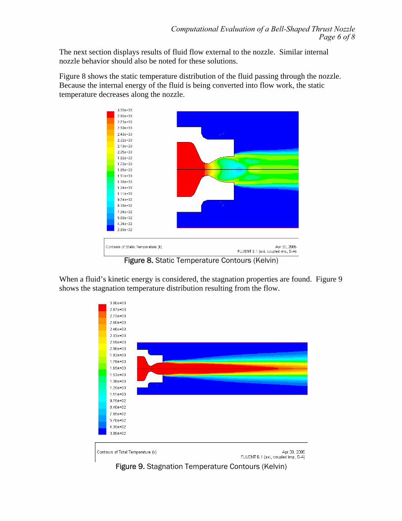
The next section displays results of fluid flow external to the nozzle. Similar internal nozzle behavior should also be noted for these solutions. Figure 8 shows the static temperature distribution of the fluid passing through the nozzle. Because the internal energy of the fluid is being converted into flow work, the static temperature decreases along the nozzle.
Figure 8. Static Temperature Contours (Kelvin)
When a fluid’s kinetic energy is considered, the stagnation properties are found. Figure 9 shows the stagnation temperature distribution resulting from the flow.
Figure 9. Stagnation Temperature Contours (Kelvin)
Computational Evaluation of a Bell-Shaped Thrust NozzlePage 6 of 8

To view the fluid’s velocity dissipation, a contour of the Mach number is displayed in Figure 10. This picture also shows the flow separation resulting from the fluid and atmospheric air.
Figure 10. Mach Number Contours
Summary: This study successfully modeled the operating characteristics of a bell-shaped thrust nozzle assuming operating conditions. Not only were the solutions helpful in visualizing fluid behavior, but also in indicating design concerns such as wall contours. Utilizing the study’s results, a nozzle was designed and manufactured. Coupled into the design process, the analysis using numerical methods proved to be a very rewarding tool. Recommendations: Because a real nozzle has been manufactured, it would be advantageous to run operational experiments and compare results with the CFD model. Initial conditions for the CFD model may be changed to find solutions under various operating conditions. The model could then be used to optimize the nozzle’s design based on performance and geometrical changes.
Computational Evaluation of a Bell-Shaped Thrust NozzlePage 7 of 8

References:
[1] Humble, Ronald; Henry, Gary; and Larson, Wiley; Space Propulsion Analysis and Design, McGraw Hill, 1995 [2] Sutton, George; Biblarz, Oscar; Rocket Propulsion Elements, Wiley, 2000 [3] Cengel, Yunus A.; Boles, Michael; Thermodynamics-An Engineering Approach, McGraw Hill, 2001 [4] Cengel, Yunus A.; Heat Transfer-A Practical Approach, McGraw Hill, 2002
Computational Evaluation of a Bell-Shaped Thrust NozzlePage 8 of 8

1N 0.225 lbf=
0 500 1000 1500 2000 2500 3000100
0
100
200
300
400
500
600Thrust vs. Exit Velocity
(m/s)
(New
tons
)
Fthrust vexit( )
vexit
Fthrust vexit( ) mdot_total vexit vinlet−( )⋅:=The thrust can now be graphed versus exit velocity:
Fthrust 113.286 lbf=Fthrust mdot_total vexit vinlet−( )⋅:=The thrust is now calculated:
"Mach 2.857"vexit 3062.7ms
:=vinlet 27.036ms
:=From "Nozzle Design Calculations":
mdot_total 0.166kgs
=mdot_total mdot_n2o mdot_wax+:=
mdot_wax 0.016kgs
:=mdot_n2o 0.150kgs
:=From "Thermochemical Calculations":
This equation assumes perfect expansion, which is valid in the case of the HERMES thrust nozzle. From previous calculations, all variables have been determined in the thrust equation. They are defined as:
F mdot_total vexit vinlet−( )⋅:=Thrust is defined on pg.484 of [2] as:
These calculations serve as a guide to approximating the thrust produced by a rocket. Once the thrust equation is defined, two uses will be shown. The first is to approximate an ideal hybrid rockets thrust, and the second is to derive an exhaust gas velocity from a thrust measurement.
Performed by: Ryan EricksonDate: Spring 2005
Thrust Calculations
Thrust CalculationsPage 1 of 2

The result is the average velocity seen at the exit of the thrust nozzle. According to these calculations, Big Boy's exhaust velocity was somewhere around Mach 1. Note that the speed of sound varies with temperature. This method may be applied to each firing, as long as the oxidizer used per time, fuel used per time, and thrust are recorded. It would also be advantageous to evaluate the speed of sound in this medium at the exhaust temperatures. The proper equations to do that are already defined in the "Nozzle Design" calculations.
vexit 1.57 103×
ms
=
vexitFthrust
mdot_totalvinlet+:=
Fthrust 37lbf:=
mdot_total 0.107kgs
=
mdot_total mdot_n2o mdot_wax+:=3.) Define the total mass flow rate:
4.) Define the average thrust measurement:
5.) Apply to rearranged for of thrust equation:
***Note: these are the approximate conditions observed in Big Boy's 2nd firing.
mdot_wax 0.05kgs
=mdot_wax600gm12sec
:=
mdot_n2o 0.057kgs
=mdot_n2o1.5lb12sec
:=1.) Define oxidizer flow rate:
2.) Average fuel mass used over time:
The second method is applied the following way:
mdot_total 0.166kgs
=
mdot_total mdot_n2omdot_n2o
9.476+:=
mdot_n2o 0.15kgs
:=1.) Define oxidizer flow rate:
2.) Define total mass flow rate:
There are two approaches to defining the total flow rate of exhaust: (1) Stoichiometric combustion can be assumed, or (2) the mass of fuel can be averaged over the burn time. In the case of the first assumption, the total mass flow rate is by the following method:
The second application of the thrust equation is to find an exhaust gas velocity from a thrust measurement and oxidizer/propellant flow rate. These values will be found experimentally.
Thrust CalculationsPage 2 of 2

Calculation References The following references were used in calculations. All reference numbers from calculation sections (excluding “Computational Evaluation of a Bell-Shaped Thrust Nozzle”) correspond to these references. [1] Kobe, K.A.; Hirth, L.J.; Couch, E.J.; Volumetric Behavior of Nitric Oxide, Journal of Chemical Engineering, 1961, 6, 229 [2] Çengel, Yunus A.; and Boles, Michael A.; Thermodynamics: An Engineering Approach, 4th Edition, McGraw Hill, 2002 [3] IGI Inc. (www.igiwax.com) [4] McBride, Bonnie; Gordon, Sanford; Reno, Martin; NASA TM 4513- Coefficients for Calculating Thermodynamic and Transport Properties of Individual Species, NASA, 1993 (also obtained at http://cea.grc.nasa.gov/ ) [5] Turns, Stephen R.; An Introduction to Combustion: Concepts and Applications, 2nd Edition, McGraw Hill, 2000 [6] Humble, Ronald W.; Henry, Gary N.; Larson, Wiley J.; Space Propulsion Analysis and Design, McGraw Hill, 1995 [7] BETE Inc. (www.bete.com) [8] Perry, Robert H.; Perry’s Chemical Engineers’ Handbook, 7th Edition, McGraw Hill, 1997 [9] Reid, Robert C.; Prausnitz, John M.; Poling, Bruce E,; The Properties of Gases and Liquids, 4th Edition, McGraw Hill, 1987