Embed Size (px)
Citation preview
1
Numerical Investigation of Polyphenylene Sulfide Basis
Composite Materials for Airframe Structure
*Prof.Dr.Najim A .Saad, ** Asist.Prof.Dr. Mohammed S. Hamzah, *Dr. Ahmed F. Hamzah
*Babylon University, ** University of Technology
ABSTRACT
This paper deals numerical simulations of composite material with
Polyphenylene sulfide matrix and carbon and glass fibres; the main goal is determine
ability of using proposed composite materials in airframe structure by numerical
simulations, to predict the elastic properties of composite, CADEC software is used to
show the effect of fiber type, number of layers and fiber orientation on the elastic
properties. For this purpose the computational simulations by ANSYS 13 were carried
out. The results show that the ability of using composite materials under study as skin of
wing of aircraft under effects of pure inertial loads.
Key words: Polyphenylene sulfide, ANSYS, aircraft, numerical simulation, skin of
wing.
INTRODUCTION:
Traditional materials for aircraft construction include aluminum, steel and
titanium. The primary benefits that composite components can offer are reduced weight
and assembly simplification. In the past twenty years, the use of composite materials in
the aircraft industry, among others, has grown immensely. Composite systems offer an
advantage over traditional aircraft materials (metals) because they tend to exhibit higher
strength/weight and stiffness/weight ratios than metals, thus making the aircraft lighter
and improving performance. [1]
In the early 1970s, composite materials were introduced to airframe structures to
increase the performance and life of the airframe. In 1977, the National Aeronautics and
Space Administration (NASA) Advanced Composite Structures Program introduced the
use of composites in primary structures in commercial aircraft, i.e., the Boeing 737
horizontal stabilizer. In 1994, the Advanced General Aviation Transport Experiments
consortium, led by NASA and supported by the Federal Aviation Administration (FAA),
industry, and academia, revitalized composite material product development in general
aviation by developing cost-effective composite airframe structures. Modern improved
composite materials and matured processes have encouraged commercial aircraft
companies to increase the use of composites in primary and secondary structures.
Driven by the demand for fuel-efficient, light-weight, and high-stiffness structures that
have fatigue durability and corrosion resistance, the Boeing 787 Dreamliner is designed
with more than 50 percent composite structure, marking a striking milestone in
composite usage in commercial aviation. Meanwhile, the Airbus A350 commercial

2
airplane is being designed with a similar percentage of composite materials in its
structure. [2, 3]
Thermoplastic composite materials have shown great promise as materials for
current and future aircraft components. It is likely that thermoplastic composite
components will enter airframe service in the near future in the form of replacement
components which were previously manufactured from metals or thermosetting
composites such as graphite/epoxy. Thermoplastic resins offer a number of advantages
over conventional thermosetting resins such as epoxies. Thermoplastics exhibit
chemical and impact resistance and may be used over a wide range of temperatures.
They have a very low level of moisture uptake which means their mechanical properties
are less degraded under hot/wet conditions. [4, 5]
A wide range of thermoplastics are available and in common use today. In the
area of high performance thermoplastics, polyetheretherketone (PEEK) and
Polyphenylene sulfide (PPS) are probably the most widely reported thermoplastic
resins. [6]
Composite structures can be analyzed by using analytical and numerical
methods. Generally, when a composite structure is modeled, some assumptions and
simplifications have to be made. [7, 8] Rapid developments in computer hardware make
the finite element method of complex determination responses increasingly applicable.
The FEM is used worldwide to simulate the composite materials processes and has
become a reliable numerical simulation technology. There are many FEM packages
such as (MSC/NASTRAN, SUPERFORGE, ABAQUS, ALGOR, DIEKA, and
ANSYS). [9, 10 and 11]
The overall objective of this research was to provide guidance into structural
substantiation of composite airframe structures under repeated loads through an efficient
approach that weighs both the economic aspects of certification and the timeframe
required for testing, while ensuring safety.
In present paper the mechanical failure studies of composite materials with the
basis of Polyphenylene sulfide (PPS) reinforced with glass and carbon fibers as the skin
of wing of aircraft numerically by using a commercial finite element code ANSYS 13.
Modeling Process:
The computer program (ANSYS) is prepared for obtaining the optimum
composite material it is possible used in the wing of aircraft structure through using
fatigue failure criterion like (fatigue life, safety factor, …etc.) because is estimated that
90% of service failures of components that undergo movement of one form or another
can be attributed to fatigue. Fatigue is one of the most common failure modes in all
structural materials, including composite materials.
The element SHELL 93 (isoparametric 8-node structural shell) is used in idealization of
wing structure in this model.

3
The model is restricted to take the effects of pure inertial loads on the structural
behaviour of wing structure, so any effects associated with 3-D motion such as aero-
dynamic pressure, induced shock wave, drag, and aero-heating loads (thermal loads) are
neglected, and the inertia loads were interpreted as point loads. [21]
The displacement constraints (the boundary conditions for which the
displacement of all DOF equal zero) were made at the region where the wing joined the
fuselage structure. [21]
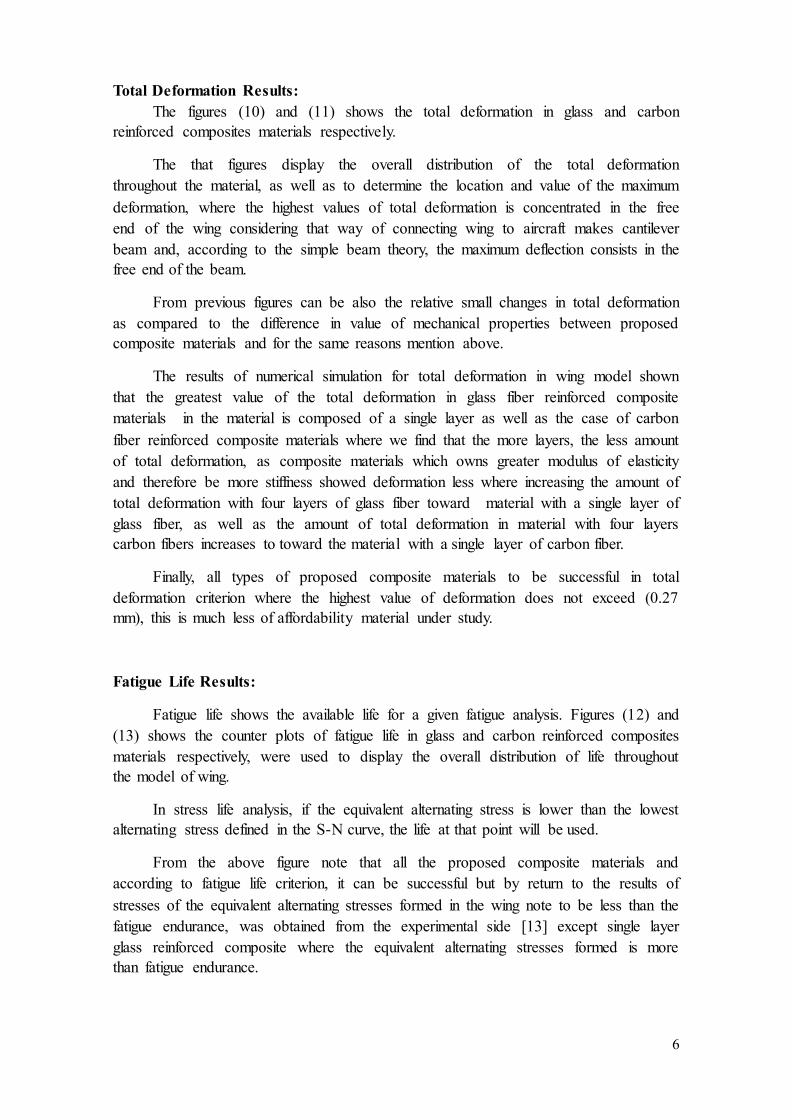
The variety of materials is restricted to base plate and upper skin to determine the
composite material is valid for using for this purpose, on the other hand the stiffeners
and honeycomb cross is assumed to be consisting single material are restricted to
isotropic elastic material (special Ti alloy) used for manufacturing this type of wing as
shown in the figure (1), the chemical composition and mechanical properties of basic
materials used in these study shown in the table (1).
Material Properties:
The mechanical properties (Young's modulus, Shear modulus and Poisson's
ratio) of the composite system used in this study are determined theoretically dependent
on theoretical equations and by using the software called computer aided design
environment for composite (CADEC 12) which is a specialized program specialist to
composite materials and which depends on the use of theoretical equations for
composite materials such as laminated theory, rule of mixture and other theories to
calculate the engineering constants for composite Materials. Table (2) contains elastic
constant of the composites materials of this work, on the other hand in the fatigue
simulation, it will need for the data that represents the number of cycles until failure
versus applied stress on the samples for each number of cycles and this data cannot be
predicted mathematically such elastic properties so we will be using the experimental
results of the fatigue test, which obtained from another research of our own. [21]
Finite Element Modeling:
The developments of suitable method, more accurately, for analysis various
engineering structure are needed in order to investigate their behaviour under different
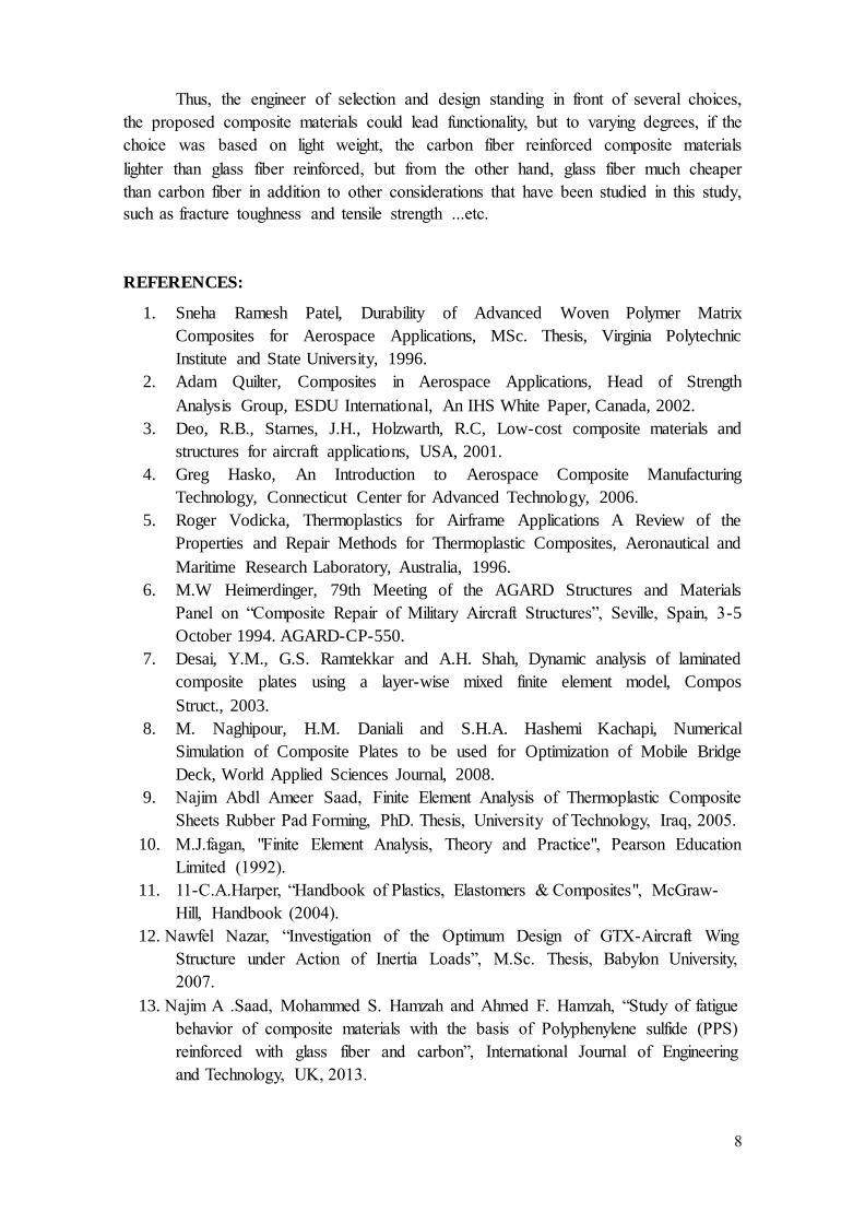
loading condition. Whole dimensions of wing of Aircraft adopted for present work is
shown in the figure (2). [24]
The model is consists of three parts lower skin, upper skin and longitudinal and
transvers honeycomb stiffeners.
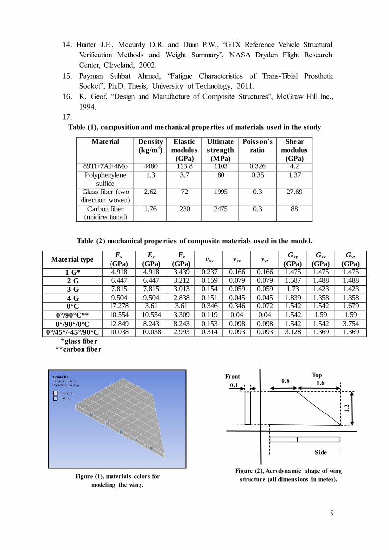
Skins Modeling:
The external skins are assumed to be consisting of lower plate and upper plate
only as shown in figure (3).
The skins are created as governed surface with (162 keypoints) as shown in the figure
(4).
4
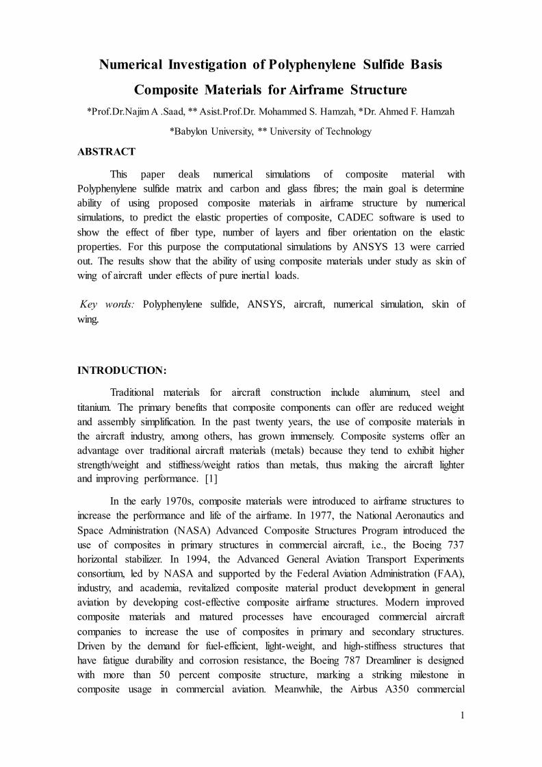
The first step represents the keypoints creation, the second step represents the
areas creation by keypoints that facilitates the element creation step where the elements
are created as governed parts by the areas in the second step. The lower and upper plates
each one is consisting of 60 rectangular plates and 8 triangular plates, the lace is
consisting 20 rectangular plates.
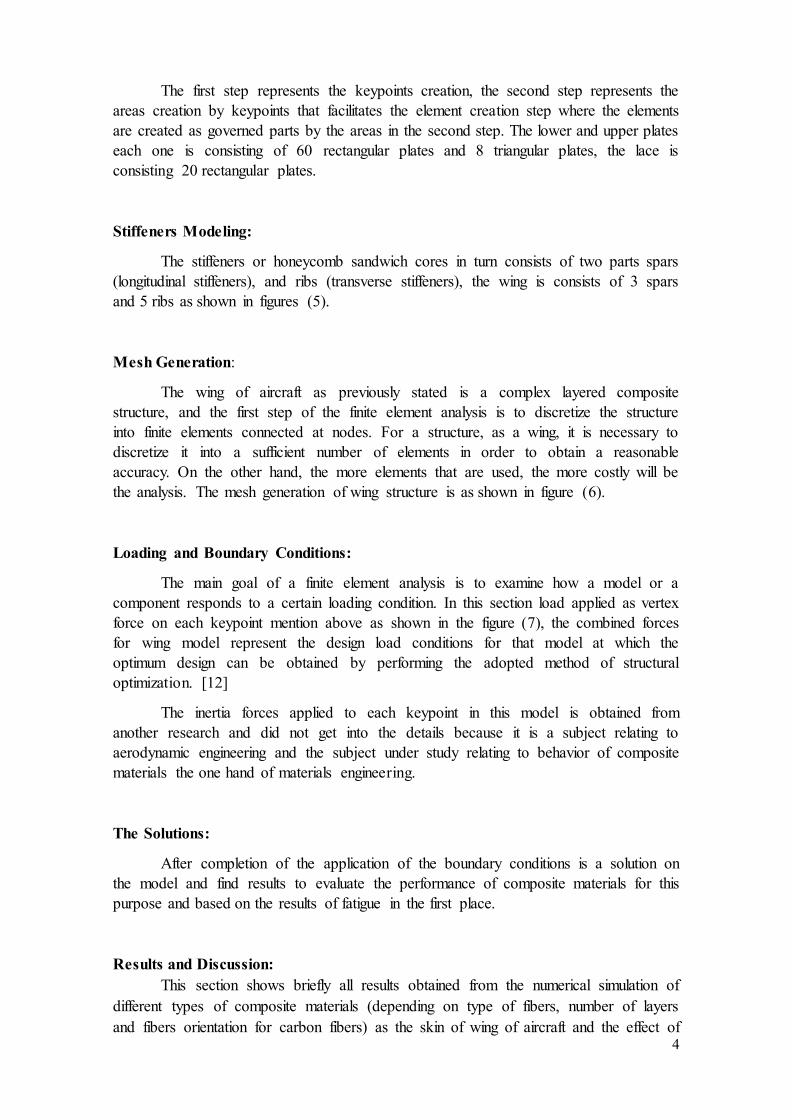
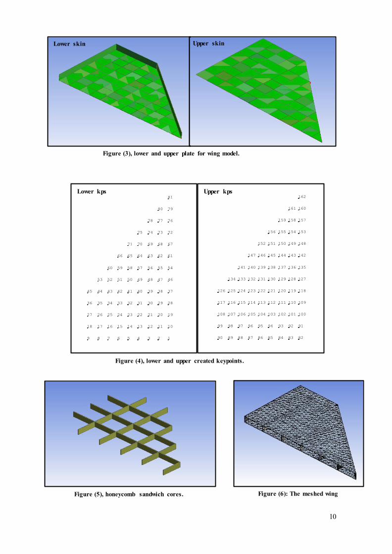
Stiffeners Modeling:
The stiffeners or honeycomb sandwich cores in turn consists of two parts spars
(longitudinal stiffeners), and ribs (transverse stiffeners), the wing is consists of 3 spars
and 5 ribs as shown in figures (5).
Mesh Generation:
The wing of aircraft as previously stated is a complex layered composite
structure, and the first step of the finite element analysis is to discretize the structure
into finite elements connected at nodes. For a structure, as a wing, it is necessary to
discretize it into a sufficient number of elements in order to obtain a reasonable
accuracy. On the other hand, the more elements that are used, the more costly will be
the analysis. The mesh generation of wing structure is as shown in figure (6).
Loading and Boundary Conditions:
The main goal of a finite element analysis is to examine how a model or a
component responds to a certain loading condition. In this section load applied as vertex
force on each keypoint mention above as shown in the figure (7), the combined forces
for wing model represent the design load conditions for that model at which the
optimum design can be obtained by performing the adopted method of structural
optimization. [12]
The inertia forces applied to each keypoint in this model is obtained from
another research and did not get into the details because it is a subject relating to
aerodynamic engineering and the subject under study relating to behavior of composite
materials the one hand of materials engineering.
The Solutions:
After completion of the application of the boundary conditions is a solution on
the model and find results to evaluate the performance of composite materials for this
purpose and based on the results of fatigue in the first place.
Results and Discussion:
This section shows briefly all results obtained from the numerical simulation of
different types of composite materials (depending on type of fibers, number of layers
and fibers orientation for carbon fibers) as the skin of wing of aircraft and the effect of
5
this materials on wing behaviour under maximum inertia loads as mention above
represented by the equivalent alternating stress, total deformation, fatigue life and safety
factor.
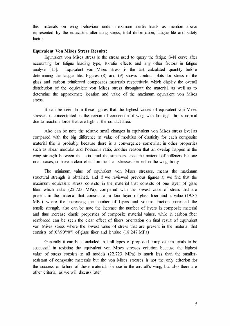
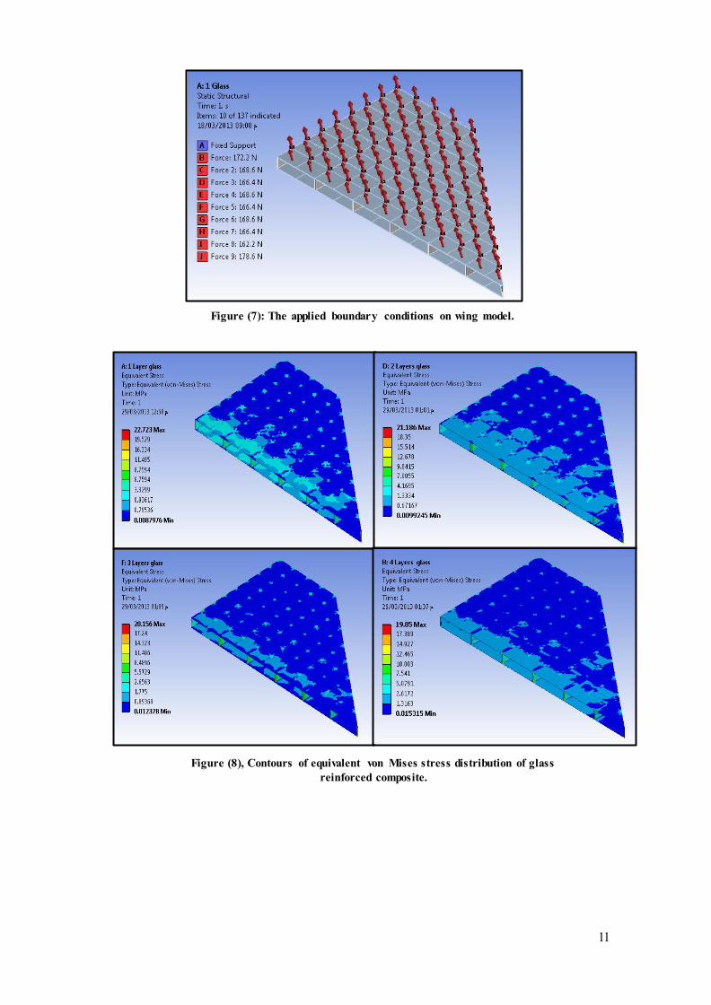
Equivalent Von Mises Stress Results:
Equivalent von Mises stress is the stress used to query the fatigue S-N curve after
accounting for fatigue loading type, R-ratio effects and any other factors in fatigue
analysis [15]. Equivalent von Mises stress is the last calculated quantity before
determining the fatigue life. Figures (8) and (9) shows contour plots for stress of the
glass and carbon reinforced composites materials respectively, which display the overall
distribution of the equivalent von Mises stress throughout the material, as well as to
determine the approximate location and value of the maximum equivalent von Mises
stress.
It can be seen from these figures that the highest values of equivalent von Mises
stresses is concentrated in the region of connection of wing with fuselage, this is normal
due to reaction force that are high in the contact area.
Also can be note the relative small changes in equivalent von Mises stress level as
compared with the big difference in value of modulus of elasticity for each composite
material this is probably because there is a convergence somewhat in other properties
such as shear modulus and Poisson’s ratio, another reason that an overlap happen in the
wing strength between the skins and the stiffeners since the material of stiffeners be one
in all cases, so have a clear effect on the final stresses formed in the wing body.
The minimum value of equivalent von Mises stresses, means the maximum
structural strength is obtained, and if we reviewed previous figures it, we find that the
maximum equivalent stress consists in the material that consists of one layer of glass
fiber which value (22.723 MPa), compared with the lowest value of stress that are
present in the material that consists of a four layer of glass fiber and it value (19.85
MPa) where the increasing the number of layers and volume fraction increased the
tensile strength, also can be note the increase the number of layers in composite material
and thus increase elastic properties of composite material values, while in carbon fiber
reinforced can be seen the clear effect of fibers orientation on final result of equivalent
von Mises stress where the lowest value of stress that are present in the material that
consists of (0°/90°/0°) of glass fiber and it value (18.247 MPa)
Generally it can be concluded that all types of proposed composite materials to be
successful in resisting the equivalent von Mises stresses criterion because the highest
value of stress consists in all models (22.723 MPa) is much less than the smaller-
resistant of composite materials but the von Mises stresses is not the only criterion for
the success or failure of these materials for use in the aircraft's wing, but also there are
other criteria, as we will discuss later.
6
Total Deformation Results:
The figures (10) and (11) shows the total deformation in glass and carbon
reinforced composites materials respectively.
The that figures display the overall distribution of the total deformation
throughout the material, as well as to determine the location and value of the maximum
deformation, where the highest values of total deformation is concentrated in the free
end of the wing considering that way of connecting wing to aircraft makes cantilever
beam and, according to the simple beam theory, the maximum deflection consists in the
free end of the beam.
From previous figures can be also the relative small changes in total deformation
as compared to the difference in value of mechanical properties between proposed
composite materials and for the same reasons mention above.
The results of numerical simulation for total deformation in wing model shown
that the greatest value of the total deformation in glass fiber reinforced composite
materials in the material is composed of a single layer as well as the case of carbon
fiber reinforced composite materials where we find that the more layers, the less amount
of total deformation, as composite materials which owns greater modulus of elasticity
and therefore be more stiffness showed deformation less where increasing the amount of
total deformation with four layers of glass fiber toward material with a single layer of
glass fiber, as well as the amount of total deformation in material with four layers
carbon fibers increases to toward the material with a single layer of carbon fiber.
Finally, all types of proposed composite materials to be successful in total
deformation criterion where the highest value of deformation does not exceed (0.27
mm), this is much less of affordability material under study.
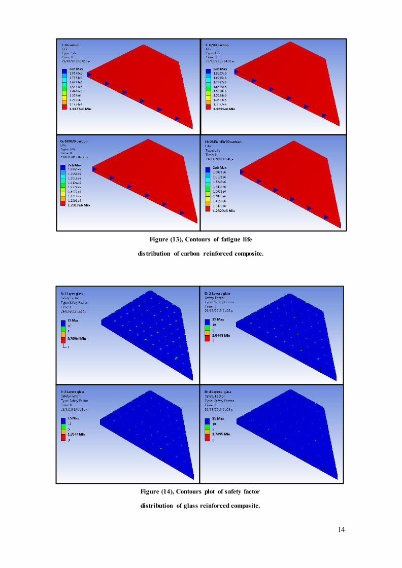
Fatigue Life Results:
Fatigue life shows the available life for a given fatigue analysis. Figures (12) and
(13) shows the counter plots of fatigue life in glass and carbon reinforced composites
materials respectively, were used to display the overall distribution of life throughout
the model of wing.
In stress life analysis, if the equivalent alternating stress is lower than the lowest
alternating stress defined in the S-N curve, the life at that point will be used.
From the above figure note that all the proposed composite materials and
according to fatigue life criterion, it can be successful but by return to the results of
stresses of the equivalent alternating stresses formed in the wing note to be less than the
fatigue endurance, was obtained from the experimental side [13] except single layer
glass reinforced composite where the equivalent alternating stresses formed is more
than fatigue endurance.

7
Fatigue Safety Factor Results:
The figures (14) and (15) shows counter plots with respect to fatigue failure at a
given design life in glass and carbon reinforced composites materials respectively.
The maximum equivalent stress failure theory states that a particular
combination of principal stresses causes failure if the maximum equivalent stress (𝜎�e)
in a structure equals or exceeds a specific stress limit (𝜎�limit):
𝜎�e ≥ 𝜎�limit
Expressing the theory as a design goal: 𝜎𝑒
𝜎𝑙𝑖𝑚𝑖𝑡< 1
An alternate but less common definition states that fracturing occurs when the
maximum equivalent stress reaches or exceeds the ultimate strength of the material [16]:
𝜎𝑒𝜎𝑢𝑡
In ANSYS, Maximum factor of safety displayed is 15, values less than one
indicate failure before the design life has been reached. It can be noticed in previous
figures the material which consist of three layers of carbon has the best value of safety
factor, so the minimum value of safety factor for this material is (2.289), but It is
obvious that all materials are safe because it's safety factor value is more than 1 which
indicate that failure will not take place before the design life is reached except the
material contain one layer of glass fiber where the minimum value of safety factor for
this material is (0.706) and these is less than one which indicate that failure will take
place before the design life is reached .
Conclusions:
From the numerical simulation results it can be concluded that it is possible to
use the proposed composite materials (except No. 1) in the manufacture of skin in the
wing of aircraft while keeping the same material stiffeners which consists of a titanium
alloy, so if we compare the density of composite materials under study (1.43 g/cm3 as
average) with the density of titanium alloy (4.48 g/cm3) it is possible to reduce the
weight of skin by (68%) and this means increased efficiency and reduced fuel
consumption due to weight reduction also not forget the low-cost resulting from the
ease of manufacturing in addition a cheap cost of polymeric materials compared with
titanium alloys.
But if we compare these composite materials with aluminum alloy such as
(90Al+2.4Mg+0.23Cr+6.4Zn+0.97Zr) alloy, which are sometimes used in the
manufacture of skin of the wing, which owns density (2.82 g/cm3), it is also possible to
replace these composite materials while reducing the weight of the skin by (50%) in
addition to the benefits mentioned above.
8
Thus, the engineer of selection and design standing in front of several choices,
the proposed composite materials could lead functionality, but to varying degrees, if the
choice was based on light weight, the carbon fiber reinforced composite materials
lighter than glass fiber reinforced, but from the other hand, glass fiber much cheaper
than carbon fiber in addition to other considerations that have been studied in this study,
such as fracture toughness and tensile strength ...etc.
REFERENCES:
1. Sneha Ramesh Patel, Durability of Advanced Woven Polymer Matrix
Composites for Aerospace Applications, MSc. Thesis, Virginia Polytechnic
Institute and State University, 1996.
2. Adam Quilter, Composites in Aerospace Applications, Head of Strength
Analysis Group, ESDU International, An IHS White Paper, Canada, 2002.
3. Deo, R.B., Starnes, J.H., Holzwarth, R.C, Low-cost composite materials and
structures for aircraft applications, USA, 2001.
4. Greg Hasko, An Introduction to Aerospace Composite Manufacturing
Technology, Connecticut Center for Advanced Technology, 2006.
5. Roger Vodicka, Thermoplastics for Airframe Applications A Review of the
Properties and Repair Methods for Thermoplastic Composites, Aeronautical and
Maritime Research Laboratory, Australia, 1996.
6. M.W Heimerdinger, 79th Meeting of the AGARD Structures and Materials
Panel on “Composite Repair of Military Aircraft Structures”, Seville, Spain, 3-5
October 1994. AGARD-CP-550.
7. Desai, Y.M., G.S. Ramtekkar and A.H. Shah, Dynamic analysis of laminated
composite plates using a layer-wise mixed finite element model, Compos
Struct., 2003.
8. M. Naghipour, H.M. Daniali and S.H.A. Hashemi Kachapi, Numerical
Simulation of Composite Plates to be used for Optimization of Mobile Bridge
Deck, World Applied Sciences Journal, 2008.
9. Najim Abdl Ameer Saad, Finite Element Analysis of Thermoplastic Composite
Sheets Rubber Pad Forming, PhD. Thesis, University of Technology, Iraq, 2005.
10. M.J.fagan, "Finite Element Analysis, Theory and Practice", Pearson Education
Limited (1992).
11. 11-C.A.Harper, “Handbook of Plastics, Elastomers & Composites", McGraw-
Hill, Handbook (2004).
12. Nawfel Nazar, “Investigation of the Optimum Design of GTX-Aircraft Wing
Structure under Action of Inertia Loads”, M.Sc. Thesis, Babylon University,
2007.
13. Najim A .Saad, Mohammed S. Hamzah and Ahmed F. Hamzah, “Study of fatigue
behavior of composite materials with the basis of Polyphenylene sulfide (PPS)
reinforced with glass fiber and carbon”, International Journal of Engineering
and Technology, UK, 2013.
9
14. Hunter J.E., Mccurdy D.R. and Dunn P.W., “GTX Reference Vehicle Structural
Verification Methods and Weight Summary”, NASA Dryden Flight Research
Center, Cleveland, 2002.
15. Payman Suhbat Ahmed, “Fatigue Characteristics of Trans-Tibial Prosthetic
Socket”, Ph.D. Thesis, University of Technology, 2011.
16. K. Geof, “Design and Manufacture of Composite Structures”, McGraw Hill Inc.,
1994.
17.
Table (1), composition and mechanical properties of materials used in the study
Material Density
(kg/m3)
Elastic
modulus
(GPa)
Ultimate
strength
(MPa)
Poisson’s
ratio
Shear
modulus
(GPa) 89Ti+7Al+4Mo 4480 113.8 1103 0.326 4.2
Polyphenylene sulfide
1.3 3.7 80 0.35 1.37
Glass fiber (two direction woven)
2.62 72 1995 0.3 27.69
Carbon fiber (unidirectional)
1.76 230 2475 0.3 88
Table (2) mechanical properties of composite materials used in the model.
Material type Ex
(GPa)
Ey
(GPa)
Ez
(GPa) νxy νxz νyz
Gxy
(GPa)
Gxz
(GPa)
Gyz
(GPa)
1 G* 4.918 4.918 3.439 0.237 0.166 0.166 1.475 1.475 1.475
2 G 6.447 6.447 3.212 0.159 0.079 0.079 1.587 1.488 1.488
3 G 7.815 7.815 3.013 0.154 0.059 0.059 1.73 1.423 1.423
4 G 9.504 9.504 2.838 0.151 0.045 0.045 1.839 1.358 1.358
0°C 17.278 3.61 3.61 0.346 0.346 0.072 1.542 1.542 1.679
0°/90°C** 10.554 10.554 3.309 0.119 0.04 0.04 1.542 1.59 1.59
0°/90°/0°C 12.849 8.243 8.243 0.153 0.098 0.098 1.542 1.542 3.754
0°/45°/-45°/90°C 10.038 10.038 2.993 0.314 0.093 0.093 3.128 1.369 1.369
*glass fiber **carbon fiber
Figure (1), materials colors for
modeling the wing.
0.8 1.6
1.2 8
0.1
Top
view Front
view
Side
view
Figure (2), Aerodynamic shape of wing
structure (all dimensions in meter).
10
Figure (3), lower and upper plate for wing model.
Lower skin Upper skin
1
123456789
101112131415161718
192021222324252627
282930313233343536
373839404142434445
4647484950515253
54555657585960
616263646566
6768697071
72737475
767778
7980
81
POINTS
POIN NUM
1
828384858687888990
919293949596979899
100101102103104105106107108
109110111112113114115116117
118119120121122123124125126
127128129130131132133134
135136137138139140141
142143144145146147
148149150151152
153154155156
157158159
160161
162
POINTS
TYPE NUM
Figure (4), lower and upper created keypoints.
Lower kps Upper kps
Figure (5), honeycomb sandwich cores. Figure (6): The meshed wing
structure.
11
Figure (7): The applied boundary conditions on wing model.
Figure (8), Contours of equivalent von Mises stress distribution of glass
reinforced composite.

12
Figure (9), Contours of equivalent von Mises stress
distribution of carbon reinforced composite.
Figure (10), Contours of total deformation
distribution of glass reinforced composite.

13
Figure (11), Contours of total deformation
distribution of carbon reinforced composite.
Figure (12), Contours of fatigue life
distribution of glass reinforced composite.
14
Figure (13), Contours of fatigue life
distribution of carbon reinforced composite.
Figure (14), Contours plot of safety factor
distribution of glass reinforced composite.

15
Figure (15), Contours plot of safety factor
distribution of carbon reinforced composite.