Embed Size (px)
Citation preview

Research Journal of Recent Sciences _________________________________________________ ISSN 2277-2502
Vol. 1(9), 1-5, September (2012) Res.J.Recent Sci.
International Science Congress Association 1
Numerical Investigation of External Flow around the Ahmed Reference
Body Using Computational Fluid Dynamics
Chauhan Rajsinh B. and Thundil Karuppa Raj R. School of Mechanical and Building Sciences, VIT University, Vellore-632014, TN, INDIA
Available online at: www.isca.in Received 22nd March 2012, revised 29th March 2012, accepted 30th March 2012
Abstract
This paper presents a finite-element based numerical simulation for the prediction of flow around the Ahmed body. The flow
solver used is ACUSOLVE, developed by ACUSIM software. In this investigation an effort was made to investigate the fully
developed turbulent flow over Ahmed Body and to evaluate the effect of slant angle. Understanding this aerodynamic
phenomenon helps us in reducing fuel consumption, increase the stability and passenger comfort. In this study, the spalart-
allmaras (S-A) turbulence model is used in order to reduce the computational cost at high Reynolds number. Two separate
cases have been solved for two different upstream velocities and results are compared. The results are presented in the form
of drag coefficient values and flow field which includes velocity contour and velocity vector fields. The validation is carried
out by a simulation around the Ahmed body with the slant angle of 25° with stilts. The results are compared with the actual
wind-tunnel experimental data. Moreover, the capabilities of ACUSOLVE code to predict the flow around the Ahmed Body
has been analyzed by comparing the flow structure at wake region with experiments. The pre-processing & post processing
for this study is carried out with the help of HYPERMESH and HYPERVIEW software respectively.
Keywords: Ahmed Body, S-A model, CFD, wake region, drag.
Introduction
The external aerodynamics of a car determines many relevant
aspects of an automobile such as stability, comfort and fuel
consumption at high cruising speeds1. The flow around vehicles
is characterized by highly turbulent and three-dimensional
separations, and there is a growing need for more insight into
the physical features of these dynamical flows on the other
hand, and powerful numerical tools to analyze them on the other
hand. Computations based on Reynolds-Averaged Navier
Stokes Equations (RANS) are common in industry today.
Although they are very successful in predicting many parts of
the flow around a vehicle, they are unable to predict
unsteadiness in the wake region. The failure in predicting the
base pressure is the major reason for the large discrepancy in
drag prediction between experiments and numerical simulations.
In order to investigate the behavior of newly developed
turbulence models for complex geometry cases, a simplified car
model, known as the Ahmed body, has been tested by Ahmed2.
The Ahmed body is made up of a round front part, a moveable
slant plane placed in the rear of the body to study the separation
phenomena at different angles, and a rectangular box, which
connects the front part and the rear slant plane, as shown in
figure-1.
As the wake flow behind the Ahmed body is the main
contributor to the drag force, accurate prediction of the
separation process and the wake flow are the key to the
successful modelling of this case. To simulate the wake flow
accurately, resolving the near wall region using accurate
turbulence model is highly desirable. This paper will study the
effectiveness of Spalart-Allmaras (S-A) turbulence models, for
the modeling of the flow over the Ahmed body, and shows the
behavior of S-A turbulence model, as well as the effect of the
grid layout on the numerical results. This model has been
selected due to the availability of the experimental results3.
The aim of this paper is to simulate the flow around the Ahmed
Body at different velocities (i.e. V=40 m/sec and V=60 m/sec)
and study the variations in the flow at wake region with the
change in velocities. The main importance of this work is to
exhibit the capability of numerical modeling with Spalart-
Allmaras turbulence model for ACUSOLVE commercial CFD
code.
Methodology
Geometrical Modeling: The Ahmed Body model with domain
is modeled using SOLIDWORKS CAD modeling tool based on
the parameters given in figure 1. The slant angle at the rear end
is kept as 25° which is identical with the experimental model.
Figure-1
Schematic of the Ahmed Body model with 25° Slant angle2
(All dimensions are in mm)
Research Journal of Recent Sciences ______________________________________________________________ ISSN 2277-2502
Vol. 1(9), 1-5, September (2012) Res. J. Recent Sci.
International Science Congress Association 2
The geometry of the Ahmed body is shown in figure-1. The
slant angle is adjustable and is the main variable model-
parameter in the experimental investigations. In this study, only
25° slant angle was investigated. The Ahmed body, of length
(L) 1044 mm, height (H) 288 mm, and width (W) 389 mm, was
placed at 50 mm from the ground (G). The model is mounted on
four cylindrical struts with a diameter (f) of 30 mm. The
reference axis (X, Y, and Z) is linked to the model. The origins
of these axis lies at the point O located on the floor of the
ground of the wind tunnel, on the base of the model and in the
symmetry plane of the model. The computational domain starts
2 × L in front of the model and extends to 5 × L behind the
model. The width of the domain is 1.87 m and its height is 1.4
m. These dimensions are recommended as per the ERCOFTAC
workshop on Refined Turbulence Modeling4.
Figure-2
Schematic of the Ahmed Body model with Computational
Domain
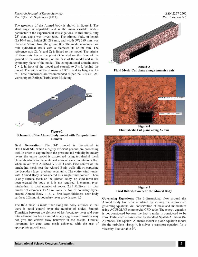
Grid Generation: The 3-D model is discretized in
HYPERMESH, which a highly efficient generic pre-processing
tool. In order to capture both the pressure and velocity boundary
layers the entire model is discretized using tetrahedral mesh
elements which are accurate and involve less computation effort
when solved with ACUSOLVE CFD code. Fine control on the
tetrahedral mesh near the Ahmed Body walls allows capturing
the boundary layer gradient accurately. The entire wind tunnel
with Ahmed Body is considered as a single fluid domain. There
is only surface mesh on the Ahmed Body; no solid mesh has
been created for body as it is not required: i. element type:
tetrahedral, ii. total number of nodes: 2.85 Millions, iii. total
number of elements: 15.55 millions, iv. No. of boundary layers
around Ahmed Body : 16, v. first layer thickness near body
surface: 0.2mm, vi. boundary layer growth rate: 1.2
The fluid mesh is made finer along the body surfaces so that
there is good control over the number of nodes. Smooth
Transition between the element of last boundary layer and core
tetra element has been assured as any aggressive transition may
not give the correct flow behavior in the results. Gradual
increment for core tetra mesh achieved with the use of
appropriate growth rate.
Figure 3
Fluid Mesh: Cut plane along symmetry axis
Figure-4
Fluid Mesh: Cut plane along X- axis
Figure-5
Grid Distribution near the Ahmed Body
Governing Equations: The 3-dimensional flow around the
Ahmed Body has been simulated by solving the appropriate
governing equations viz. conservation of mass and momentum
using ACUSOLVE commercial CFD code. The energy equation
is not considered because the heat transfer is considered to be
zero. Turbulence is taken care by standard Spalart-Allmaras (S-
A) model. The Spalart–Allmaras model is a one equation model
for the turbulent viscosity. It solves a transport equation for a
viscosity-like variable 5.

Research Journal of Recent Sciences ______________________________________________________________ ISSN 2277-2502
Vol. 1(9), 1-5, September (2012) Res. J. Recent Sci.
International Science Congress Association 3
The one-equation S-A model is given by the following equation:
Boundary Condition Setup: In AcuConsole (pre-processor for
ACUSOLVE) the fluid domain is defined. There is no solid
domain involved in study. The flow in this study is turbulent,
hence S-A turbulence model is chosen. The boundary conditions
are specified in AcuConsole pre-processor and then the file is
exported to the solver. The upstream velocities for two cases
are: 40 m/sec and 60 m/sec. The Reynolds number, based on the
length of the model, is 2.78 × 10⁶. Besides, following
Conditions were applied for solving the case: Material: Air,
Inlet: Velocity, Outlet: Pressure (Atmospheric)
Numerical Solution Approach: Solution phase is completely
automatic. The FEA software generates the element matrices,
computes nodal values and derivatives, and stores the result data
in files. These files are further used by the subsequent phase
(post-processing) to review and analyze the results.
The CFD flow solver used is ACUSOLVE, which is a General
purpose 3-dimensional, unstructured flow solver which uses the
incompressible Reynolds-averaged Navier-Stokes equations.
The solver is based on the finite element method to build a
spatial discretization of the transport equations. The velocity
field is obtained from the momentum conservation equations
and the pressure field is extracted from the mass conservation
constraint, or continuity equation, transformed into a pressure
equation. All equations are solved using Garlinkan Least Square
method. Equal order nodal interpolation for all variables are
done while solving. The computations are performed on a HPC
Cluster (12 CPU @ 2.66 GHz, 32 GB RAM). The total elapsed
CPU time is nearly 13 hours for a total of 80 time steps.
Two simulations have been carried out with the same model
dimensions, grid, boundary conditions and modeling technique
except the change in upstream velocity. The variation for
velocity is kept as 40 m/sec and 60 m/sec
Results and Discussion
Experimentally, for the 40 m/sec case, the two strong counter-
rotating vortices emanating from the slant are present and the
flow separates in the middle region of the top edge and
reattaches on the slant6. An illustration of the experimental flow
is illustrated by the sketch given below. Consequently, the
turbulence model must predict separation and reattachment on
the slant.
Figure-6
Development of the flow for the Ahmed Body with 25° slant
angle
Case: 1 Velocity: 40m/sec: The spalart–allmaras model for
which the flow remains attached, predicts separation just past
the top of the slant, as in experiment, but does not predicts the
same reattachment seen in the experiment. The figures below
show the wake behind the body predicted using S-A turbulence
model and using experiments. We see that the simulation with
the S-A turbulence model predicts a massive separation on the
slant. The reattachment on the slant is not present clearly which
can be a possible limitation for S-A turbulence model.
Case: 2 Velocity: 60m/sec: For higher velocity also, the flow
behavior remains same as in case-1. It is almost matching with
the experimental results of 40 m/sec. The major change that is
identified is the recirculation size and location in the wake,
which is not similar to case-1. Apart from that, a recirculation
bubble is seen on the slant end which is not clearly visible in
case-1.
Figure-7
Prediction for Wake region behind the Ahmed Body for
case-1

Research Journal of Recent Sciences ______________________________________________________________ ISSN 2277-2502
Vol. 1(9), 1-5, September (2012) Res. J. Recent Sci.
International Science Congress Association 4
Figure-8
Prediction for Wake region behind the Ahmed Body for
case-2
Figure-9
Experimental Prediction for Wake region behind the
Ahmed Body for case-1
The tendency of S-A to predict a massive separation is clearly
visible in figure-7 and 8, which presents the rear slant,
centerline streamlines. We can see that with S-A model, the
wake is in good agreement for both cases with experiments. But,
the flow over the rear slant is not well predicted. The
experiments show separation at the top edge and reattachment
of the flow about half the length along the slant back. The
computation with the S-A turbulence model shows a massive
separation on slant but it does not predict the reattachment as in
the experiments for both the cases.
Drag Coefficient Comparison: The drag coefficient value
obtained with the S-A model is 0.266 for case-1 and 0.740 for
case-2. The same for the experiments by Ahmed is 0.290. This
drag coefficient computed takes into account the drag of the
model and that of the feet7. The S-A model gives the same
tendency but the drag on the slant is over-estimates. These
differences are not surprising because the simulation do not
predict correctly the flow on the slant.
Figure-10
Drag Co-Efficient Comparison
As shown in figure-10, the drag coefficient for 60 m/sec
velocity is almost three times when compared to that of 40
m/sec velocity. Hence, it can be stated that increasing velocity
by 20 m/sec gives significant rise in drag coefficient.
Wake Region Flow Structure Analysis: The analysis of the
flow structures in the wake region of the Ahmed body is
depicted in figures 11 to 13. The figures show the streamwise
velocity component at different planes behind the body8. The
wakes of the C-pillars are slightly weak in the simulation than in
experiments9. The structural analysis of the Ahmed body can be
carried out using Finite Element Techniques similar to10,11
.
Drag Co-Efficient Comparison
Experiments V=40 m/sec V=60m/sec
Figure-11
Comparison of Wake flow at X=0

Research Journal of Recent Sciences ______________________________________________________________ ISSN 2277-2502
Vol. 1(9), 1-5, September (2012) Res. J. Recent Sci.
International Science Congress Association 5
Experiments V=40 m/sec V=60m/sec
Figure-12
Comparison of Wake flow at X=80mm
Experiments V=40 m/sec V=60m/sec
Figure-13
Comparison of Wake flow at X=500mm
Conclusion
The flow field for the external flow over the Ahmed body can
be simulated by computational approach. Simulation with S-A
turbulence model, has been carried out for two different
velocities for the generic Ahmed body with 25° slant angle. The
turbulence model predicts the topology of the flow correctly. At
the 25° slant angle, the simulation predicts massive separation
but the flow over the rear slant is not well predicted. Whereas
the experiment shows reattachment about half-way down the
center of the face. Following are some other outcomes that can
be listed out from this study: The comparison for the drag
coefficient for both velocity values has been carried out and it is
found that increasing velocity by 20 m/sec gives thrice the more
drag coefficient value. The numerical modeling of the flow
around Ahmed Body gives clear understanding flow structure
near the slant and at the wake region of the body. The flow
prediction capabilities for ACUSOLVE code is observed and
found that with the use of S-A turbulence model, it is able to
predict the flow well in agreement with the experimental results.
Acknowledgments
The support of the presented work by Altair Engineering-India
is gratefully acknowledged. Special thanks to Dr. Marc Ratzel
and Mr. Rajesh Krishnan for many helpful discussions and for
the attribution of HPC.
References
1. Hucho W.H., Aerodynamics of Road Vehicles, SAE
International, Warrendale, PA (1998)
2. Ahmed S.R., Ramm G. and Faltin G., Some Salient
Features of the Time-Averaged Ground Vehicle, SAE
Paper 840300 (1984)
3. Lienhart H. and Becker S., Flow and Turbulence
Structures in the Wake of a Simplified Car Model, SAE
Paper 2003-01-0656 (2003)
4. Manceau Rand and Bonnet J.P., Proceedings of 10th Joint
ERCOFTAC (SIG-15)/IAHR/QNET-CFD Workshop on
Refined Turbulence Modeling, Poitiers, France (2002)
5. John D. Anderson, Jr. Computational Fluid Dynamics-
basics with application, McGraw-Hill series in mechanical
engineering (1995)
6. Guilmineau E., Computational Study of Flow around a
Simplified Car Body, Journal of Wind Engineering and
Industrial Applications, 96, 1207-1217 (2008)
7. Guilmineau E., Numerical simulation with a DES
approach, SAE Paper 2010-01-0758 (2010)
8. Minguez M., Pasquetti R. and Serre E., High-Order Large
Eddy Simulation of Flow Over the “Ahmed Body” Car
Model, Physics of Fluids, 20, 095101 (2008)
9. Kapadia S., Roy S. and Wurtzler K., Detached eddy
simulation over a reference Ahmed car model, AIAA
paper no. 2003-0857 (2003)
10. Kumar Krishan and Aggarwal M.L., A Finite Element
Approach for Analysis of a Multi Leaf Spring using CAE
Tools, Research Journal of Recent Sciences, 1(2), 92-96
(2012)
11. Purkar T. Sanjay and Pathak Sunil, Aspect of Finite
Element Analysis Methods for Prediction of Fatigue Crack
Growth Rate, Research Journal of Recent Sciences,1(2) 85
-91 (2012)