Embed Size (px)
Citation preview

NUMERICAL EVALUATION OF WIND-INDUCED ENVIRONMENT AROUND BUILDINGS WITH REFUGE FLOOR
W. K. Chow1 and J. Li2 1 Chair Professor, Department of Building Services Engineering, The Hong Kong Polytechnic
University, Hong Kong, China, [email protected] 2 College of Architecture and Civil Engineering, Beijing University of Technology, Beijing,
China, [email protected]
ABSTRACT
Refuge floors should be provided in all buildings exceeding 25 storeys for fire safety following the Hong Kong Building Code on means of escape, and at least two opposite external walls should be open to provide adequate cross ventilation. Wind-induced flow around two adjacent rectangle-plan high-rise buildings with or without opening refuge floors were investigated by computational fluid dynamics (CFD) in this paper. The flow pattern and pressure distributions around these two buildings were addressed. The results are believed to be helpful for the proper design of the smoke control system and ventilation system in buildings.
KEYWORDS: CFD, REFUGE FLOOR, WIND-INDUCED FLOW, HIGH-RISE BUILDING
Introduction
Modeling the wind environment associated with proposed or existing buildings is important for the wind engineering and civil construction, as large wind-induced load may result in the instability and eventual collapse of a structure. Such studies can also be applied to the smoke control system design, buoyancy-driven roof vent design, the effects of wind on fire spread or other related systems in fire safety engineering [Kandola (2002)]. The wind-induced flow field around a building might be determined by the building shape or size, building configurations, and the wind characteristic. The flow field around a building with openings in the side wall might be more complicated than around those completely sealed buildings. Understanding the wind-induced environment around buildings under this condition might be more important for the ventilation and smoke exhaust system design and operation. Locating inlet opening near high-pressure surfaces of a building and exit openings at lower pressure ones are believed to increase the ventilation efficiency through the vents. Therefore, an understanding of air flow around the building is necessary to a well-ventilated system design. In a city with high-density buildings, the effects of the arrangement of the surrounding buildings should be considered.
Following Hong Kong Building Code on means of escape (MOE) [Buildings Department (1996)], refuge floors should be provided in all buildings exceeding 25 storeys in height above the lowest ground storey for fire safety, and at not more than 20 storeys and 25 storeys respectively for industrial and non-industrial buildings from any other refuge floor. The refuge area is required to be separated from the remainder of the building and is protected by fire rated construction elements such as walls and floor. The clear height of the refuge floor should be not less than 2.3 m, and the area for refuge should be open-sided above safe parapet height on at least two opposite sides to provide adequate cross ventilation. Insufficient
The Seventh Asia-Pacific Conference on Wind Engineering, November 8-12, 2009, Taipei, Taiwan

The Seventh Asia-Pacific Conference on Wind Engineering, November 8-12, 2009, Taipei, Taiwan
ventilation would impair the safety of the refuge floor. Therefore, wind environment under this condition should be studied carefully, whether the smoke can enter the refuge floor should be presented.
Wind environment around a building is often studied by the wind tunnel test or numerical studies by computational fluid dynamics (CFD). Conducting wind-tunnel studies sometimes may be expensive and time consuming, particularly in the event of additional test requirements with modified building and/or environmental configurations. On the other hand, a technique based on numerical simulation of wind flow condition around buildings appears attractive as a potential alternative tool [Stathopoulos (1996)]. CFD simulation can provide detailed information of wind flow field, and can offer more flexibility when exploring a variety of building designs and modifications and their impact on the flow around them. However, wind tunnel studies have been proved to be quite useful for development, evaluation, validation and general performance assessment of CFD methods.
Wind-induced flow around two adjacent rectangle-plan high-rise buildings with or without opening refuge floors would be investigated by CFD in this paper. The geometry and distribution of these two buildings are shown in Figure 1. The front building is 50 m long, 30 m wide and the height is 80 m, and the back building is 80 m long, 50 m wide and 150 m high. The distance between the two buildings is 50 m. The flow pattern and pressure distributions around these two buildings would be addressed. The main interest is the effect of the opening refuge floor on the wind environment in the zone between these two buildings.
Mathematical Model
The flow around a building is a highly turbulent and complex flow field. The fundamental equations governing the motion of steady, incompressible and turbulent flows are the averaged Navier-Stokes equations and continuity equation that can be expressed as:
0xU
i
i =∂∂ (1)
jii
j
j
i
jii
ij uu)
xU
xU
(v[xx
P1xU
U ′′−∂
∂+
∂∂
∂∂
+∂∂
ρ−=
∂∂
(2) The turbulence fluxes of momentum jiuu ′′ are important terms that govern turbulent diffusion and need to be specified by certain turbulence model to fulfill the closure of the equation set. A number of turbulence models are available ranging from simple algebraic models to second moment closure models developed during the past decades. For simplicity, the Reynolds-averaged Navier-Stokes (RANS) approach is adopted in this study. The standard k-ε model proposed by Launder and Spalding [(1974)], which is regarded as still the most successful turbulence model in engineering application at cost-effectiveness is used for closing the equation set by virtue of the concept of turbulence diffusivity. The k-ε model relates the
Inle
t bou
ndar
y
Free boundary
220
m
50 mx
z
150
m
80 m
38 m
38
m
48 m
48
m
46m
Free
bou
ndar
y
50 m
220 m
140
m
50 m 30 m
50 m
45
m
30 m
x
y
80 m
(a) x-z plane
(b) y plane
Figure 1: Geometry and Distribution of the Buildings

The Seventh Asia-Pacific Conference on Wind Engineering, November 8-12, 2009, Taipei, Taiwan
turbulent diffusivity νt to the mean turbulent kinetic energy k and the dissipation rate of turbulence ε by:
iji
j
j
itji
2
t k32)
xU
xU
(uukC δ+∂
∂+
∂∂
υ−=′′ε
=υ µ (3)
where ijδ is the Kronecker symbol. k and ε can be solved by the following transport equations:
ε−+∂∂
συ
+υ∂∂
=∂∂
kjk
t
jjj P]
xk)[(
xxkU (4)
kC
kPC]
x)[(
xxU
2
2k1j
t
jjj
ε−
ε−+
∂ε∂
συ
+υ∂∂
=∂ε∂
ε
(5)
)xU
xU
(xU
Pi
j
j
i
j
itk ∂
∂+
∂∂
∂∂
υ=
Values of empirical constants in the above equations are: C1 = 1.44, C2 = 1.92, Cµ = 0.09, CD = 1.0, σk = 1.0, σε = 1.3 To save effort in developing CFD code from ‘scratch’, PHOENICS 3.4 [(2001)] was
selected as the simulator. This code has accessible subroutines so that equations and parameters concerned can be checked and modified. Verification works on applying this CFD code to simulate wind-induced flow around the building were reported everywhere. The predicted results agreed satisfactorily with the experiment, giving confidence in applying this CFD code to study the wind-induced flow.
Numerical Experiments
Four scenarios designated as S1, S2, S3 and S4 with different building configurations are considered:
S1: wind flow over the two buildings directly, no refuge floor is considered; S2: wind flow over the two buildings directly, and one open refuge floor is added in
lower building, it is located about 38 m above the street, as shown in Figure 1; S3: wind flow over the two buildings directly, and two refuge floors are added in the
higher building, they are located at 48 m and 100 m above the ground floor respectively, as shown in Figure 1;
S4: wind flow over the two buildings directly, and both buildings have refuge floors, the positions are the same as in S2 and S3.
The height of the refuge floor is 4 m, and all the refuge floors have the same horizontal plan as the building within.
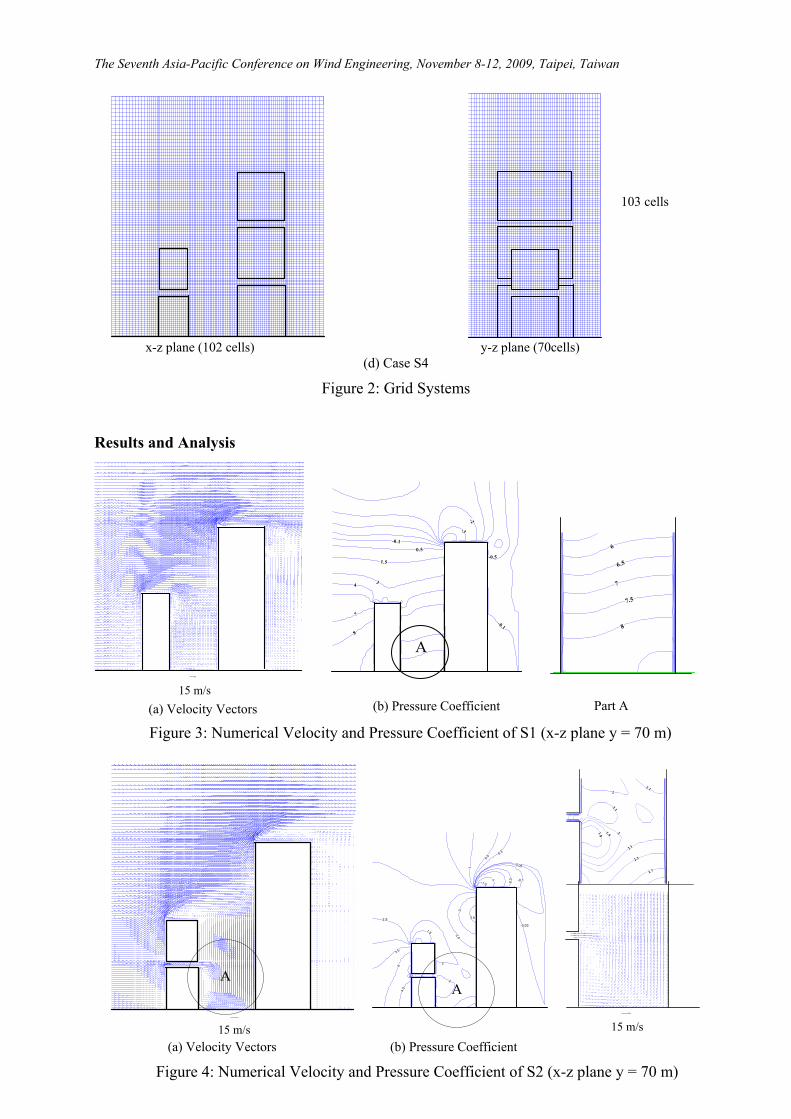
Computational domain is extended as 220 m long, 140 m wide and 220 m wide (see Figure 1). Conservation equations for mass, momentum together with transport equations for the turbulent variables k and ε are discretized into finite difference forms by the finite-volume method in a staggered grid system. The grid system for all cases are shown in Figure 2, the mesh is fine in the area around the exterior wall of the buildings and refuge floors. The algorithm SIMPLEST was used for solving the velocity-pressure linked equations. The convergence criterion is to check whether the sum of normalized absolute residuals in each control volume for all variables is less than 10-3.
The inlet wind velocity is 8m/s and other boundaries are set as free boundaries.

The Seventh Asia-Pacific Conference on Wind Engineering, November 8-12, 2009, Taipei, Taiwan
x-z plane (104cells) y-z plane (70 cells)
(a) Case S1
x-z plane (102 cells) y-z plane (70 cells)
(b) Case S2
x-z plane (102 cells) y-z plane (70 cells)
(c) Case S3
90 cells
102 cells
102 cells
The Seventh Asia-Pacific Conference on Wind Engineering, November 8-12, 2009, Taipei, Taiwan
x-z plane (102 cells) y-z plane (70cells)
(d) Case S4
Figure 2: Grid Systems
Results and Analysis
Part A
4
7
8
1.5
0.5
-0.1
-2
-3
-0.5
-0.1
3
6
7
8
6.5
7.5
A
15 m/s (a) Velocity Vectors (b) Pressure Coefficient
Figure 3: Numerical Velocity and Pressure Coefficient of S1 (x-z plane y = 70 m)
(b) Pressure Coefficient
Figure 4: Numerical Velocity and Pressure Coefficient of S2 (x-z plane y = 70 m)
15 m/s
2.5
3.5
4
1.5
2
2
2.5
3
1
0.5
0.3
-0.05
-0.1
-0.3
-0.03
-1
-1.5
3.5
4.5
1.8
2.1
2.3
2.7
1.9 2
22.1
2.1
A
A
15 m/s
(a) Velocity Vectors
103 cells
The Seventh Asia-Pacific Conference on Wind Engineering, November 8-12, 2009, Taipei, Taiwan
Selected numerical results for all the four cases are shown from Figures 3 to 6. Numerical velocity and pressure distributions for scenario S1 are shown in Figure 3. Positive pressure distributions are found in the region above the lower building roof and the zone behind the lower building. This is different from the wind-induced field around only a single building where negative pressure distributions are observed. Flow recirculation is observed at the high level wall region of the lower building, and wind-induced air-flow in the region between the two buildings is observed to flow downwards. All these mean that if the vents are positioned at the rear wall and the roof of the lower building, the vent efficiency might be greatly reduced. However, wind-induced environment around the back higher building shows the same wind flow field as the wind flow over a single building, negative pressure distributions are found at the roof and the leeward of the building. Smoke exhaust vent located at this area will increase the exhaust rate.
Numerical results for scenario S2 are shown in Figure 4. As a refuge floor is added in the front lower building, the pressure at the zone between the two buildings is lower than those in S1, and wind-induced flow is observed to be flowing down. Recirculation airflow is
(a) Velocity Vectors
3
3.5
4
2
1.7
2.5
-0.3
-0.3
-1
-0.5
-0.2
-0.04
1 1.3
1.5
1.6
1.7
1.9
1.4
1.51.6
1.3
-0.01
1.5
15 m/s 15 m/s
A
A
(a) Velocity Vectors (b) Pressure Coefficient Part A
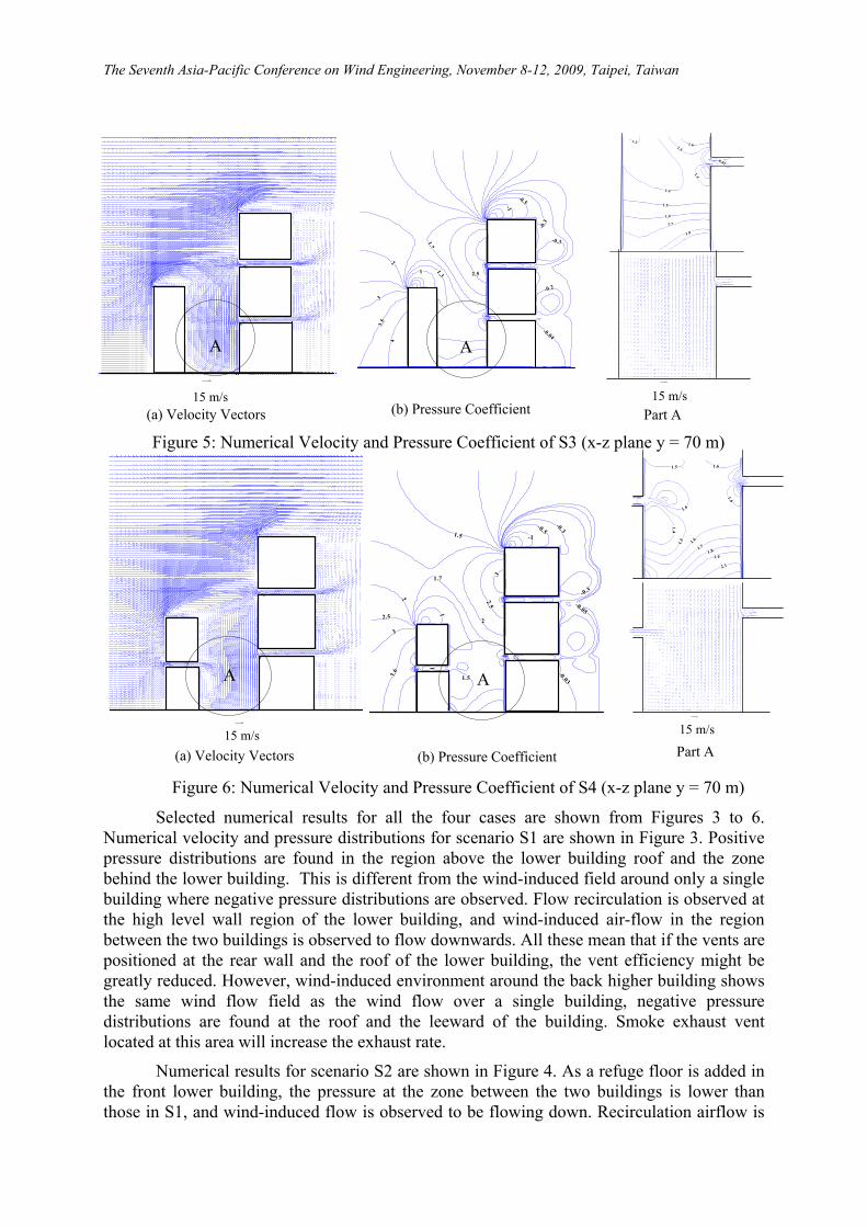
Figure 5: Numerical Velocity and Pressure Coefficient of S3 (x-z plane y = 70 m)
15 m/s Part A
3.6
3
2.5
2
1.7
11
1.5
2
3
-1
-0.5
-0.3
-0.3
-0.05
-0.03
2.5
1.5
1.6
1.7
1.9
1.5
1.4
1.6
1.5 1.6
1.6
2.1
1.8
(a) Velocity Vectors (b) Pressure Coefficient
15 m/s
Part A 15 m/s
A
A
Figure 6: Numerical Velocity and Pressure Coefficient of S4 (x-z plane y = 70 m)

The Seventh Asia-Pacific Conference on Wind Engineering, November 8-12, 2009, Taipei, Taiwan
found to form at the region close to the rear wall below the refuge floor. If the vent outlet is located at this area, smoke might re-circulate here if the fire-induced vertical upward velocity is not so high. Same as in S1, vent openings are not suitable to be located at the roof and the rear wall of the lower building.
Numerical velocity and pressure coefficient distributions are shown in Figure 5. Same as in S1 and S2, positive pressure distributions are also found in the roof region and the rear region of the front lower building, and the value is lower than in S2. Re-circulation airflow is observed to be formed at the region above the two refuge floors behind the higher building. Smoke exhaust openings cannot be located at the roof of the lower building because some exhaust smoke might flow into the refuge floor of the higher building. Also, it might not be suitable to position the vent at the rear wall of the higher building close to the refuge floor.
For scenario S4, wind-induced environment around the two buildings is illustrated in Figure 6. Re-circulating airflows are found below the refuge floor for the lower building and above the refuge floor for the higher building. It is not suitable to the position smoke exhaust in the wall close to these regions, and same as S3, the smoke exhaust vent also cannot be positioned in the roof of the lower building.
Conclusions
Wind environment around buildings with or without refuge floor were studied by numerical method. Wind-induced velocity and pressure distributions are presented. Simulation results showed that the wind-induced environment is affected by the surrounding topography greatly. Wind-induced pressure might be positive other than negative at the roof and leeward of the front building. Ventilation or smoke exhaust efficiency might decrease if the vent openings are located in this region. For the arrangement of the building like those shown in this paper, smoke exhaust vents are not suitable to be located at the roof for the front lower building because the exhaust smoke will flow into the refuge floor of the back higher building. Moreover, outlet opening is also suggested not to be located at the rear wall below or above the refuge floor for the front building and the back building respectively. All these results might be useful in designing the smoke exhaust system and ventilation system.
References
Buildings Department (1996), “Code of practice for the provision of means of escape in case of fire”, Hong Kong.
Kandola, B.S. (2002), “Introduction to Mechanics of Fluid”, The SFPE Handbook of Fire Protection Engineering, 3rd Edition, Dinenno, P.J. (Ed.), National Fire Protection Association, Quincy, Massachusetts, USA, pp. 1-1 − 1-26.
Kim, S.E. and Boysan, F. (1999), “Application of CFD to Environmental Flows”, Journal of Wind Engineering and Industrial Aerodynamics, 81, 145-158
Launder, B.E. and Spalding, D.B. (1974), “The Numerical Computation of Turbulent Flows”, Computer Methods in Applied Mechanics and Engineering, 3(2): 269-289.
Stathopoulos, T. (1996), “Computer Simulation of Wind Environmental Conditions around Buildings”, Engineering Structures, 18(11), 876-885.
The PHOENICS POLIS, CHAM Ltd., Wimbledon Village, London, UK (2001).