Embed Size (px)
Citation preview

GTB0150 | Rev 5 May/2014 Page 1 of 19
NuAire, Inc. | 2100 Fernbrook Lane | Plymouth, MN 55447 | U.S.A | ph: 763.553.1270 | fx: 763.553.0459 | tf: 800.328.3352 | www.nuaire.com
TECHNICAL BULLETIN : GENERAL INFORMATION
NuAire Model NU‐PR797
Positive Pressure Recirculating Compounding Aseptic Isolator Performance Evaluation
Compliance to USP797
Background The United States Pharmacopeia (USP) published USP Chapter 797, Pharmaceutical Compounding ‐ Sterile Preparations. The chapter details the requirements of most every aspect of Compounded Sterile Preparations (CSP’s) from definitions of quality assurance programs practices and procedures necessary to provide the highest quality CSP’s to patients. Each state board of Pharmacy will determine to adopt this chapter in full, partially or with modifications and provide a timetable to accomplish the task.
Compounding Aseptic Isolators (CAI’s) as Primary Engineering Controls (PEC’s) Within the USP797 chapter many aspects of PEC’s are discussed. This includes CAI’s starting with their definition, design characteristics, placement, performance verification and general use. In regard to design characteristics, placement, performance verification and general use, the USP797 states that “It is incumbent on the compounding personnel to obtain from the manufacturer that the CAI/CACI will meet this standard.” To assure that NuAire’s CAI complies, NuAire has performed various testing to the CETA CAG‐002‐2006 as well as additional performance testing exceeding the specified requirements. To assure compliance we will review the USP797 chapter on each of the above CAI aspects and reference compliance design and/or product performance verification testing as documented in this technical bulletin. The USP 797 chapter starts with the definition of a CAI as the following:
Compounding Aseptic Isolator (CAI) ‐ A form of isolator specifically designed for compounding pharmaceutical ingredients or
preparations. It is designed to maintain an aseptic compounding environment within the isolator throughout the compounding and material transfer processes. Air exchange into the isolator from the surrounding environment should not occur unless the air has first passed through a microbial retentive filter (HEPA minimum). The USP797 chapter continues to identify design characteristics of PEC’s as discussed within the “Facility Design and Environmental Controls” section. This section as stated below provides the following design characteristic requirements for compliance. Alongside the requirements, NuAire compliance is stated.
GTB0150 | Rev 5 May/2014 Page 2 of 19
NuAire, Inc. | 2100 Fernbrook Lane | Plymouth, MN 55447 | U.S.A | ph: 763.553.1270 | fx: 763.553.0459 | tf: 800.328.3352 | www.nuaire.com
Design Characteristics Requirements of USP797 NuAire Compliance
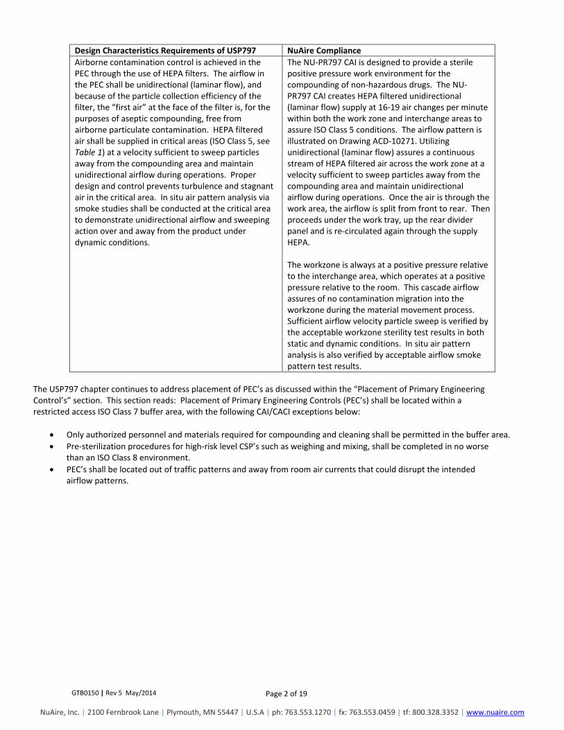
Airborne contamination control is achieved in the PEC through the use of HEPA filters. The airflow in the PEC shall be unidirectional (laminar flow), and because of the particle collection efficiency of the filter, the “first air” at the face of the filter is, for the purposes of aseptic compounding, free from airborne particulate contamination. HEPA filtered air shall be supplied in critical areas (ISO Class 5, see Table 1) at a velocity sufficient to sweep particles away from the compounding area and maintain unidirectional airflow during operations. Proper design and control prevents turbulence and stagnant air in the critical area. In situ air pattern analysis via smoke studies shall be conducted at the critical area to demonstrate unidirectional airflow and sweeping action over and away from the product under dynamic conditions.
The NU‐PR797 CAI is designed to provide a sterile positive pressure work environment for the compounding of non‐hazardous drugs. The NU‐PR797 CAI creates HEPA filtered unidirectional (laminar flow) supply at 16‐19 air changes per minute within both the work zone and interchange areas to assure ISO Class 5 conditions. The airflow pattern is illustrated on Drawing ACD‐10271. Utilizing unidirectional (laminar flow) assures a continuous stream of HEPA filtered air across the work zone at a velocity sufficient to sweep particles away from the compounding area and maintain unidirectional airflow during operations. Once the air is through the work area, the airflow is split from front to rear. Then proceeds under the work tray, up the rear divider panel and is re‐circulated again through the supply HEPA. The workzone is always at a positive pressure relative to the interchange area, which operates at a positive pressure relative to the room. This cascade airflow assures of no contamination migration into the workzone during the material movement process. Sufficient airflow velocity particle sweep is verified by the acceptable workzone sterility test results in both static and dynamic conditions. In situ air pattern analysis is also verified by acceptable airflow smoke pattern test results.
The USP797 chapter continues to address placement of PEC’s as discussed within the “Placement of Primary Engineering Control’s” section. This section reads: Placement of Primary Engineering Controls (PEC’s) shall be located within a restricted access ISO Class 7 buffer area, with the following CAI/CACI exceptions below:
Only authorized personnel and materials required for compounding and cleaning shall be permitted in the buffer area.
Pre‐sterilization procedures for high‐risk level CSP’s such as weighing and mixing, shall be completed in no worse than an ISO Class 8 environment.
PEC’s shall be located out of traffic patterns and away from room air currents that could disrupt the intended airflow patterns.

GTB0150 | Rev 5 May/2014 Page 3 of 19
NuAire, Inc. | 2100 Fernbrook Lane | Plymouth, MN 55447 | U.S.A | ph: 763.553.1270 | fx: 763.553.0459 | tf: 800.328.3352 | www.nuaire.com
CAI’s and CACI’s shall be placed in an ISO Class 7 buffer area unless they meet all of the following conditions:
Placement Requirements of USP797 NuAire Compliance
The Isolator shall provide isolation from the room and maintain ISO Class 5 during dynamic operating conditions, including transferring ingredients, components, and devices into and out of the Isolator and during preparation of CSP’s.
The NU‐PR797 CAI provides isolation from the room and maintains ISO Class 5 conditions during dynamic operating conditions, including transfer of work materials into and out of the Isolator during preparations of CSP’s. This is verified by the acceptable test results of the workzone sterility test (both static and dynamic) and the product Ingress and Egress test.
Particle counts sampled approximately 6 to 12 inches upstream of the critical exposure site shall maintain ISO Class 5 levels during compounding operations.
The NU‐PR797 CAI maintains ISO Class 5 conditions upstream of the critical exposure site during compounding operations. This is verified by the acceptable test results of the workzone sterility test (both static and dynamic).
Not more than 3520 particles (0.5 µm and larger) per m3 shall be counted during material transfer, with the particle counter probe located as near to the transfer door as possible without obstructing the transfer.
The NU‐PR797 CAI maintains ISO Class 5 conditions during the material transfer process with the material located near as possible to the door. This is verified by the acceptable test results of the product Ingress and Egress test.
It is incumbent on the compounding personnel to obtain documentation from the manufacturer that the CAI/CACI will meet this standard when located in environment where the background particle counts exceed ISO Class 8 for 0.5 µm and larger particles. When Isolators are used for sterile compounding, the recovery time to achieve ISO Class 5 air quality shall be documented and internal procedures developed to ensure that adequate recovery time is allowed after material transfer before and during compounding operations.
The NU‐PR797 CAI provides ISO Class 5 conditions as demonstrated by the documented test results and thus can be located outside and ISO Class 8 environment. Preparation Ingress and Egress test results indicated that all particle counts were well below ISO Class 5 conditions. No wait or purge time is required during the material transfer process.
If the PEC is a CAI or CACI that does not meet the requirements above or is a LAFW or BSC that cannot be located within an ISO Class 7 buffer are, then only low‐risk level non‐hazardous and radiopharmaceutical CSP’s pursuant to a physician order for a specific patient may be prepared and administration of CSP shall commence within 12 hours of preparation or as recommended in the manufacturer’s package insert, whichever is less. Performance verification testing to the CAG‐002‐2006 on all aspects of the NU‐PR797 CAI is recorded on the subsequent pages. Additional testing was performed using biological challenges to demonstrate workzone airflow patterns from a cross contamination perspective. This testing included the sidewall area, just under the IV pole in the direct compounding area with and without TPN bags in place. The results indicate that no cross contamination occurred within 14 inches of the workzone sidewall and 12 inches between work products in the direct compounding area. The results also indicate the importance of using the unidirectional “first air” during the compounding process to assure product sterility. General use of the NU‐PR797 CAI including cleaning and disinfecting the compounding area and personnel cleansing and garbing should follow the USP797 chapter unless stated below. Cleaning and disinfecting the compounding area should follow the USP797 chapter for practices and frequencies. These practices shall be included in written Standard Operating Procedures (SOP’s) and shall be followed by all compounding personnel. Personnel cleansing and garbing should also follow the USP797 chapter except for the following:

GTB0150 | Rev 5 May/2014 Page 4 of 19
NuAire, Inc. | 2100 Fernbrook Lane | Plymouth, MN 55447 | U.S.A | ph: 763.553.1270 | fx: 763.553.0459 | tf: 800.328.3352 | www.nuaire.com
Personnel Garbing Exception of USP797 NuAire Compliance
When CAI’s and CACI’s are the source of the ISO Class 5 (see Table 1) environment, the garbing and gloving requirements for compounding personnel should be as described above, unless the isolator manufacturer can provide written documentation based on validated environmental testing that any component(s) of PPE or personnel cleansing are not required.
The NU‐PR797 CAI performance verification test results based on the CETA CAG‐002‐2006, NuAire recommends at a minimum, all basic clothing and personal hygiene requirements should be met. No shoe, head, facial hair or face covers are required. Use standard pharmacy gown, perform hand hygiene and don sterile, powder‐free gloves. During material movement process, gloves should be sanitized with adequate frequency with an effective disinfectant.
Conclusion The performance verification test results based on the CETA CAG‐002‐2006 indicate that the NuAire NU‐PR797 CAI meets and exceeds the requirements of the USP 797 for providing an ISO Class 5 environment. The test results also indicate the CAI continues to meet the above requirements for use outside a clean room maintaining ISO Class 5 conditions during both product movement in and out of the CAI as well as the dynamic compounding process itself. In addition to the performance verification testing, cross contamination testing was performed. The cross contamination results indicate the benefit of a full size supply HEPA filter producing unidirectional (laminar airflow). The results can also be used to aid in the generation of efficient and effective work practices. Work practices should always be performed aseptically during the compounding process. Below, briefly reviewed are some base aseptic work practices. These work practices along with the testing results should provide a base for which to generate standard compounding work instructions.
a. After proper introduction into the Isolator of supply items required for and limited to the assigned operations, they are so arranged that a clear, uninterrupted path of unidirectional (laminar airflow)or “first air” will bathe all critical sites at all times during the planned procedures. That is, no objects may be placed above an exposed critical site in a vertical position.
b. All supply items are arranged in the Isolator working from dirty (work material entry point) to clean (Direct Compounding Area (DCA)) to reduce clutter and to provide maximum efficiency and order for the flow of work.
c. All procedures are performed in a manner designed to minimize the risk of touch contamination. Gloves are sanitized with
adequate frequency with an approved disinfectant. d. All rubber stoppers of vials and bottles and the neck of ampules are sanitized with 70% isopropyl alcohol before the
introduction of a needle or spike for the removal of product. e. After the preparations of every admixture, the contents of the container are thoroughly mixed and then inspected for the
presence of particulate matter, evidence of incompatibility, or other defects. f. After procedures are completed, used syringes, bottles, vials, and other supplies are removed or discarded, but with a
minimum of exit and re‐entry into the Isolator to minimize the risk of introducing contamination into the septic work space. The above information along with the various testing results provides location, operation, and usage information required by the USP 797. Additional work practice information is available from USP and ASHP.

GTB0150 | Rev 5 May/2014 Page 5 of 19
NuAire, Inc. | 2100 Fernbrook Lane | Plymouth, MN 55447 | U.S.A | ph: 763.553.1270 | fx: 763.553.0459 | tf: 800.328.3352 | www.nuaire.com

GTB0150 | Rev 5 May/2014 Page 6 of 19
NuAire, Inc. | 2100 Fernbrook Lane | Plymouth, MN 55447 | U.S.A | ph: 763.553.1270 | fx: 763.553.0459 | tf: 800.328.3352 | www.nuaire.com
Supply HEPA Filter Integrity Testing: (REF. CETA CAG‐002, 2.05) Purpose: This test determines the integrity of all HEPA filters, filter housings, and filter mounting frames to the IEST‐RP‐CC034. The Isolator shall be set at operational airflows for this test. Instrument:
ATI TDA‐2E Aerosol Photometer
Sinclair‐Phoenix SG‐30 Smoke Generator Procedure:
1. Open front hinged window exposing workzone interior. 2. Remove supply HEPA diffusers. 3. Turn on Isolator blower. 4. Polyalphaolefin (PAO) aerosol is introduced upstream of the HEPA filter by placing supply tube in the rear center of the
workzone over the intake slots. 5. Sample the upstream challenge using the port provided to verify the challenge requirement of 10 to 90 micrograms per liter
is supplied and set the photometer to 100%. 6. The HEPA filter and periphery are scanned by passing the photometer probe across the filter, using slightly overlapping
strokes. Scanning shall be done at the transverse rate of not more than 2 in. /sec. (51mm/sec). Acceptance Criteria: When scanning, a leakage from any point shall not exceed 0.01% of the upstream concentration. Conclusion: No leaks were detected exceeding 0.01% of upstream concentration.

GTB0150 | Rev 5 May/2014 Page 7 of 19
NuAire, Inc. | 2100 Fernbrook Lane | Plymouth, MN 55447 | U.S.A | ph: 763.553.1270 | fx: 763.553.0459 | tf: 800.328.3352 | www.nuaire.com
Airflow Testing (REF. CETA CAG‐002, 2.01) Purpose: This test is performed to verify that the Isolator meets the airflow requirements. Instrument:
TSI 8355 Thermo anemometer
Ring Stand Procedure:
1. Place thermo anemometer and ring stand in main chamber and adjust on a horizontal plane 6 inches (152mm) from the supply diffuser.
2. With window open take readings on the grid provided with no readings taken closer than 6 inches (152mm) from inside perimeter and record results
Acceptance Criteria:
1. Average downflow velocity > 35 fpm (.18 m/s) minimum. 2. Individual readings must be within + 20 (factory) + 25% (field) percent or + 16 fpm of the average downflow velocity,
whichever is greater. Inches (mm):
600 6
(152) 11.91 (303)
17.82 (453)
23.73 (663)
29.64 (753)
35.55(903)
41.46(1053)
47.37(1203)
53.25(1353)
6 (152)
40 44 44 44 46 45 39 43 36
10 (254)
31 36 39 41 45 40 38 36 30
14 (356)
24 31 29 27 29 26 28 26 30
Conclusion: Average airflow velocity and range meets acceptance criteria.
Average velocity: 36 fpm Allowable Airflow Range: 20 fpm to 52 fpm Actual Airflow Range: 24 fpm to 46 fpm
GTB0150 | Rev 5 May/2014 Page 8 of 19
NuAire, Inc. | 2100 Fernbrook Lane | Plymouth, MN 55447 | U.S.A | ph: 763.553.1270 | fx: 763.553.0459 | tf: 800.328.3352 | www.nuaire.com
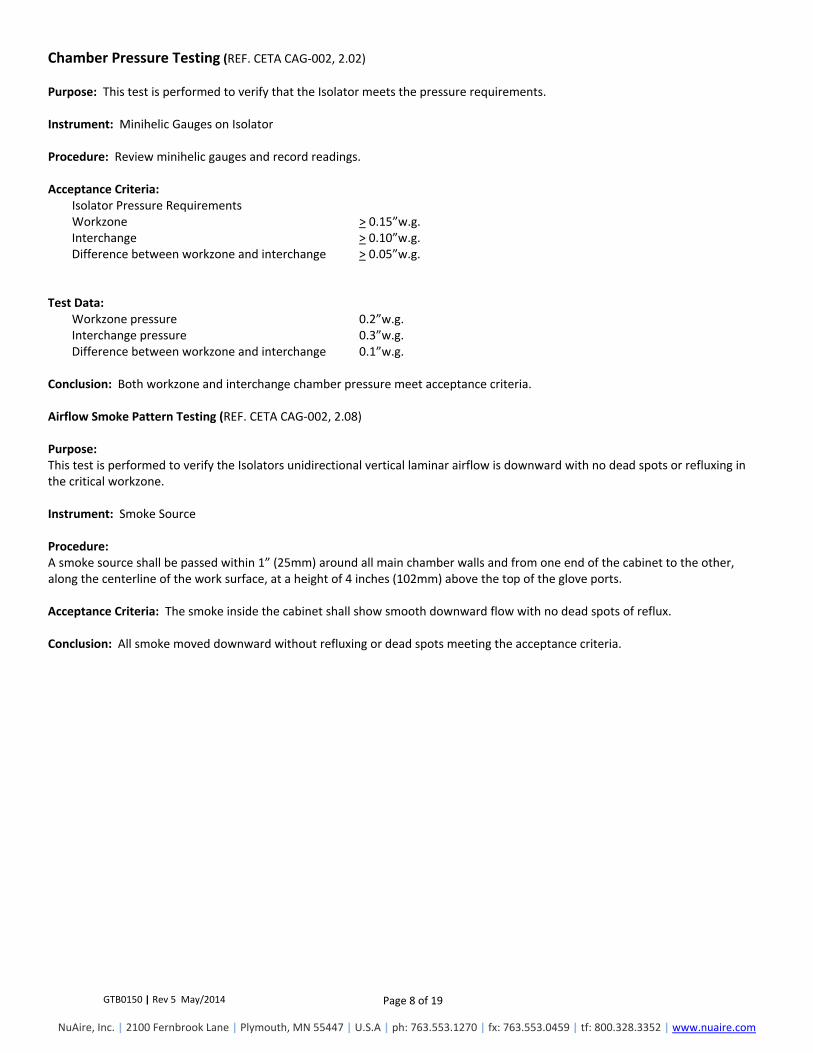
Chamber Pressure Testing (REF. CETA CAG‐002, 2.02) Purpose: This test is performed to verify that the Isolator meets the pressure requirements. Instrument: Minihelic Gauges on Isolator Procedure: Review minihelic gauges and record readings. Acceptance Criteria:
Isolator Pressure Requirements Workzone > 0.15”w.g. Interchange > 0.10”w.g. Difference between workzone and interchange > 0.05”w.g.
Test Data:
Workzone pressure 0.2”w.g. Interchange pressure 0.3”w.g. Difference between workzone and interchange 0.1”w.g.
Conclusion: Both workzone and interchange chamber pressure meet acceptance criteria. Airflow Smoke Pattern Testing (REF. CETA CAG‐002, 2.08) Purpose: This test is performed to verify the Isolators unidirectional vertical laminar airflow is downward with no dead spots or refluxing in the critical workzone. Instrument: Smoke Source Procedure: A smoke source shall be passed within 1” (25mm) around all main chamber walls and from one end of the cabinet to the other, along the centerline of the work surface, at a height of 4 inches (102mm) above the top of the glove ports. Acceptance Criteria: The smoke inside the cabinet shall show smooth downward flow with no dead spots of reflux. Conclusion: All smoke moved downward without refluxing or dead spots meeting the acceptance criteria.

GTB0150 | Rev 5 May/2014 Page 9 of 19
NuAire, Inc. | 2100 Fernbrook Lane | Plymouth, MN 55447 | U.S.A | ph: 763.553.1270 | fx: 763.553.0459 | tf: 800.328.3352 | www.nuaire.com
Product Protection Cross Contamination Biological Test: Purpose: Three different sets of tests were performed to quantify the ability of the Compounding Isolator to provide cross contamination protection of products that are being manipulated within the workzone. Biological testing was chosen because the test protocol could easily be adapted within the Compounding Isolator. The NSF/ANSI 49:2002 cross contamination test uses a nebulizer to aerosolize bacterial spores (B. Subtilis) into the workzone air stream. The bacterial spores are then either swept away in the workzone laminar airflow to be HEPA filtered or collected by agar plates or vacuum samplers. Analyzing the collected results indicates workzone laminar airflow patterns to aid in understanding Isolator performance and work practices. The first test is an NSF/ANSI 49:2002 cross contamination test that is performed on the work surface both right and left sides. The second and third test is a modified biological test run at the IV pole height to evaluate cross contamination at a higher level, in addition to downstream airflow patterns with and without IV bags present. Instrument:
Nebulizer w/Bacillus Subtilis no less than 5.0 x 10⁴
Six AGI‐30 samplers (flow rate calibrated at 12.5 Lpm) containing 20 mL of sterile diluent.
Procedure, First Test: 1. First cross contamination test, set up and run following NSF/ANSI 49:2002. 2. Route tube for nebulizer in through a glove port and then seal with plastic and tape. Place three control plates around the base of the nebulizer (front and both sides) to collect control quantities of bacteria to verify the challenge.
3. Place two rows of 5 plates, with the first row centered on a line 14” from sidewall and a second row directly behind the first row. 4. Test per NSF/ANSI 49:2002 (run nebulizer for 5 minutes, stop, continue to run the Isolator for 15 minutes, collect plates, and incubate at 99°F (37°C) for 48 hours.

GTB0150 | Rev 5 May/2014 Page 10 of 19
NuAire, Inc. | 2100 Fernbrook Lane | Plymouth, MN 55447 | U.S.A | ph: 763.553.1270 | fx: 763.553.0459 | tf: 800.328.3352 | www.nuaire.com
Acceptance Criteria: No more than 2 colony forming units (CFU’s) shall be formed on plates other than the control plates. Test Data:
Run 1
Right Side Run 2
Right Side Run 1
Left Side Run 2
Left Side
Control Plates Closest to Backwall 1. 23 1. 0 1. 0 1. 0Center 2. >200 2. >200 2. >150 2. >200Closest to Front 3. 0 3. 0 3. 27 3. 0
Run #1 Run #2 Front Row Back Row Front Row Back Row
Test Plates Right Side
1. 0 1. 0 1. 0 1. 02. 0 2. 0 2. 0 2. 03. 0 3. 0 3. 0 3. 04. 0 4. 0 4. 0 4. 05. 0 5. 0 5. 0 5. 06. 0 6. 0 6. 0 6. 07. 0 7. 0 7. 0 7. 08. 0 8. 0 8. 0 8. 09. 0 9. 0 9. 0 9. 010. 0 10. 0 10. 0 10. 0
Run #1 Run #2 Front Row Back Row Front Row Back Row
Test Plates Left Side
1. 0 1. 0 1. 0 1. 02. 0 2. 0 2. 0 2. 03. 0 3. 0 3. 0 3. 04. 0 4. 0 4. 0 4. 05. 0 5. 0 5. 0 5. 06. 0 6. 0 6. 0 6. 07. 0 7. 0 7. 0 7. 08. 0 8. 0 8. 0 8. 09. 0 9. 0 9. 0 9. 010. 0 10. 0 10. 0 10. 0
Conclusion: No colonies were found on the plates in either row 14” from sidewalls. Only the control plates surrounding the nebulizer to verify the challenge collected CFU’s indicating that there is no lateral airflow movement from either sidewall towards the center of the workzone.
GTB0150 | Rev 5 May/2014 Page 11 of 19
NuAire, Inc. | 2100 Fernbrook Lane | Plymouth, MN 55447 | U.S.A | ph: 763.553.1270 | fx: 763.553.0459 | tf: 800.328.3352 | www.nuaire.com
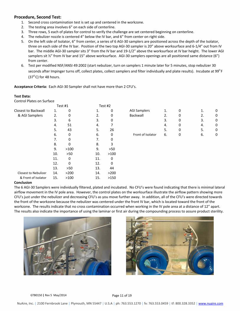
Procedure, Second Test: 1. Second cross contamination test is set up and centered in the workzone. 2. The testing area involves 6” on each side of centerline. 3. Three rows, 5 each of plates for control to verify the challenge are set centered beginning on centerline. 4. The nebulizer nozzle is centered 4” below the IV bar, and 6” from center on right side. 5. On the left side of Isolator, 6” from center, a series of 6 AGI‐30 samplers are positioned across the depth of the Isolator,
three on each side of the IV bar. Position of the two top AGI‐30 sampler is 20” above worksurface and 6‐1/4” out from IV bar. The middle AGI‐30 sampler sits 3” from the IV bar and 19‐1/2” above the worksurface at IV bar height. The lower AGI samplers sit ½” from IV bar and 15” above worksurface. AGI‐30 samplers openings are all positioned same distance (6”) from center.
6. Test per modified NSF/ANSI 49:2002 (start nebulizer, turn on samplers 1 minute later for 5 minutes, stop nebulizer 30
seconds after Impinger turns off, collect plates, collect samplers and filter individually and plate results). Incubate at 99F (37C) for 48 hours.
Acceptance Criteria: Each AGI‐30 Sampler shall not have more than 2 CFU’s. Test Data: Control Plates on Surface Test #1 Test #2 Closest to Backwall 1. 0 1. 0 AGI Samplers 1. 0 1. 0& AGI Samplers 2. 0 2. 0 Backwall 2. 0 2. 0
3. 6 3. 0 3. 0 3. 0 4. 51 4. 7 4. 0 4. 0 5. 43 5. 26 5. 0 5. 0 6. 0 6. 0 Front of Isolator 6. 0 6. 0 7. 0 7. 0 8. 0 8. 3 9. >100 9. >50 10. >50 10. >100 11. 0 11. 0 12. 0 12. 0 13. >50 13. 44
Closest to Nebulizer 14. >200 14. >200 & Front of Isolator 15. >100 15. >150
Conclusion The 6 AGI‐30 Samplers were individually filtered, plated and incubated. No CFU’s were found indicating that there is minimal lateral airflow movement in the IV pole area. However, the control plates on the worksurface illustrate the airflow pattern showing more CFU’s just under the nebulizer and decreasing CFU’s as you move further away. In addition, all of the CFU’s were directed towards the front of the workzone because the nebulizer was centered under the front IV bar, which is located toward the front of the workzone. The results indicate that no cross contamination occurred when working in the IV pole area at a distance of 12” apart. The results also indicate the importance of using the laminar or first air during the compounding process to assure product sterility.

GTB0150 | Rev 5 May/2014 Page 12 of 19
NuAire, Inc. | 2100 Fernbrook Lane | Plymouth, MN 55447 | U.S.A | ph: 763.553.1270 | fx: 763.553.0459 | tf: 800.328.3352 | www.nuaire.com
Procedure, Third Test: 1. Third cross contamination test is set up centered in the workzone. 2. The testing area involves 6” on each side of centerline. 3. Place 2 IV bags from IV bar in the testing area. 4. Three rows, 5 each of plates for control to verify the challenge are set centered beginning on centerline. 5. The Nebulizer nozzle is centered 4” below the IV bar, and 6” from center on right side. Its opening is ½” from first row of
control plates. 6. On the left side of Isolator, 6” from center, a series of 6 AGI‐30 samplers are positioned across the depth of the Isolator,
three on each side of the IV bar. Position of the two top AGI‐30 sampler is 20” above worksurface and 6‐1/4” out from IV bar. The middle AGI‐30 sampler sits 3” from the IV bar and 19‐1/2” above the worksurface at IV bar height. The lower AGI samplers sit ½” from IV bar and 15” above worksurface. AGI‐30 samplers openings are all positioned same distance (6”) from center.
7. Test per modified NSF/ANSI 49:2002 (start nebulizer, turn on samplers 1 minute later for 5 minutes, stop nebulizer 30
seconds after Impinger turns off, collect plates, collect samplers, filter individually and plate results). Incubate at 99F (37C) for 48 hours.
Acceptance Criteria: Each AGI‐30 Sampler shall not have more than 2 CFU’s. Test Data: Control Plates on Surface Test #1 Test #2 Closest to Backwall 1. 0 1. 0 AGI Samplers 1. 0 1. 0& AGI Samplers 2. 0 2. 0 Backwall 2. 0 2. 0
3. 6 3. 1 3. 0 3. 0 4. 0 4. 0 4. 0 4. 0 5. 0 5. 0 5. 0 5. 0 6. 0 6. 0 Front of Isolator 6. 0 6. 0 7. 0 7. 0 8. 0 8. 0 9. 1 9. 0 10. 27 10. >100 11. 0 11. 0 12. 0 12. 0 13. 5 13. 0
Closest to Nebulizer 14. >200 14. >100 & Front of Isolator 15. >100 15. >300
Conclusion: Again, the 6 AGI‐30 Samplers were evaluated in the same manner as the second test and with the same test results of no CFU’s found. Again, reviewing the control plates, the airflow pattern was slightly different in this third test. The difference is the bacterial spores didn’t travel as far on the worksurface. This seems to be caused by the addition of IV bags that impeded the lateral flow of the bacterial spores illustrating how objects, and work materials, etc., can influence airflow patterns.

GTB0150 | Rev 5 May/2014 Page 13 of 19
NuAire, Inc. | 2100 Fernbrook Lane | Plymouth, MN 55447 | U.S.A | ph: 763.553.1270 | fx: 763.553.0459 | tf: 800.328.3352 | www.nuaire.com
Workzone Sterility Test (Static/Dynamic) (REF. CETA CAG‐002, 2.10)
Purpose: This test is performed to determine to verify that the Compounding Isolator main chamber operates within ISO 14644‐1 Class 5 at 0.5 micron in both static and dynamic (surrogate compounding process) conditions. Instrument:
Met One Laser Particle Counter Model A2408
Aerosol Generator
Procedure: 1. Verify the background count in the testing room is at least 100,000 ppcf (ppcf) (3,532,000 particles per cubic meter (ppcm)). 2. If the count is too low, elevate the background levels using an aerosol generator. 3. Connect the particle counter sampling tubing to the workzone test port provided on the Isolator. Connect isokinetic probe to sampling tube within the workzone. 4. Turn on Isolator and let warm up five minutes. Turn on particle counter and flush out sample tubing line to remove latent particles. Set the particle counter to measure 0.5 micron or larger at 1 CFM sampling rate. 5. Take readings at 5 locations sequentially (no particle counter filtering between intervals) in 1‐minute intervals on a grid; in a horizontal plane as measured by the center point of the glove ports (approximately 6 inches above the worksurface). The grid location is designated as the workzone center point and each corner measured 6‐inches (152mm) from the inside perimeter. For dynamic test, place probe in measurement location, start surrogate compounding process, then start air sampling (NOTE, for center position during surrogate compounding process, probe was raised to stay above the process area).
Acceptance Criteria: No particle count reading during the 1‐minute interval should exceed 100 ppcf. In addition, since we fall within the 2 to 9 sampling locations at 5, the ISO 14644‐1 requires a statistical analysis of the upper 95% confidence level to confirm that sample levels measured meet the requirements. Test Data: Room background count: > 120,000 ppcf Test 1 (Static) Test 2 (Static) Test 3 (Dynamic) Test 4 (Dynamic) Particle counts for each test point
Left Rear 0 1 2 5 Left Front 1 0 0 0
Center 2 1 4 11 Right Rear 0 0 8 9 Right Front 1 0 1 4
Conclusion All 1‐minute interval particle counts for both static and dynamic conditions were well below the 100 ppcf level in both measurement and statistical analysis meeting and exceeding ISO Class 5 at 0.5 micron.

GTB0150 | Rev 5 May/2014 Page 14 of 19
NuAire, Inc. | 2100 Fernbrook Lane | Plymouth, MN 55447 | U.S.A | ph: 763.553.1270 | fx: 763.553.0459 | tf: 800.328.3352 | www.nuaire.com
Interchange Chamber Sterility Test: (REF. CETA CAG‐002, 2.10) Purpose: This test is performed to determine to verify that the Compounding Isolator interchange chamber operates within ISO 14644‐1 Class 5 at 0.5 micron. Instrument:
Met One Laser Particle Counter Model A2408
Aerosol Generator Procedure:
1. Verify the background count in the testing room is at least 100,000 ppcf (ppcf) (3,532,000 particles per cubic meter (ppcm)). 2. If the count is too low, elevate the background levels using an aerosol generator. 3. Connect the particle counter sampling tubing to the workzone test port provided on the Isolator. Connect isokinetic probe
to the sampling tube within the workzone. 4. Turn on Isolator and let warm up five minutes. Turn on particle counter and flush out sample tubing line to remove latent
particles. Set the particle counter to measure 0.5 micron or larger at 1 CFM sampling rate. 5. Take a reading at one center location for in 1‐minute approximately 6 inches above of the work surface.
Acceptance Criteria: No particle count reading during the 1‐minute interval should exceed 100 ppcf. Test Data: Room background count: > 120,000 ppcf Particle counts for each test point. Test 1 Test 2 Test 3 __2__ __5__ __1__ Conclusion: All 1‐minute interval particle counts were well below the 100 ppcf level meeting and exceeding ISO Class 5 at 0.5 micron.
GTB0150 | Rev 5 May/2014 Page 15 of 19
NuAire, Inc. | 2100 Fernbrook Lane | Plymouth, MN 55447 | U.S.A | ph: 763.553.1270 | fx: 763.553.0459 | tf: 800.328.3352 | www.nuaire.com
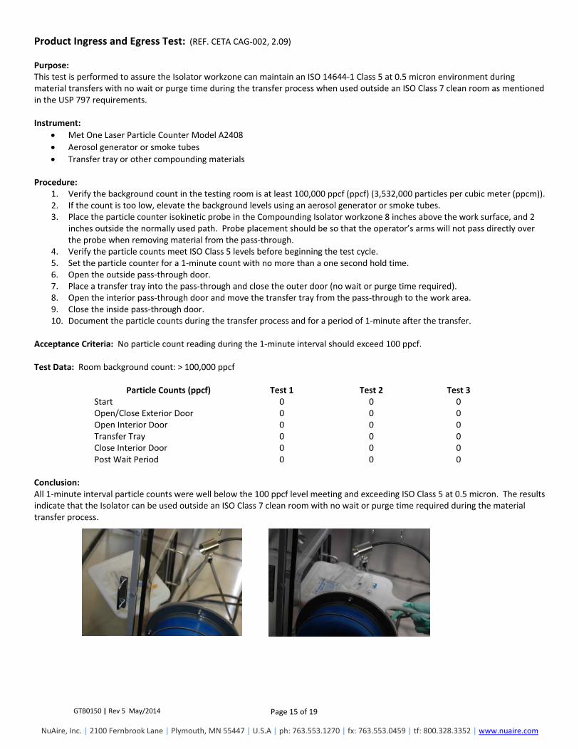
Product Ingress and Egress Test: (REF. CETA CAG‐002, 2.09) Purpose: This test is performed to assure the Isolator workzone can maintain an ISO 14644‐1 Class 5 at 0.5 micron environment during material transfers with no wait or purge time during the transfer process when used outside an ISO Class 7 clean room as mentioned in the USP 797 requirements. Instrument:
Met One Laser Particle Counter Model A2408
Aerosol generator or smoke tubes
Transfer tray or other compounding materials Procedure:
1. Verify the background count in the testing room is at least 100,000 ppcf (ppcf) (3,532,000 particles per cubic meter (ppcm)). 2. If the count is too low, elevate the background levels using an aerosol generator or smoke tubes. 3. Place the particle counter isokinetic probe in the Compounding Isolator workzone 8 inches above the work surface, and 2 inches outside the normally used path. Probe placement should be so that the operator’s arms will not pass directly over the probe when removing material from the pass‐through. 4. Verify the particle counts meet ISO Class 5 levels before beginning the test cycle. 5. Set the particle counter for a 1‐minute count with no more than a one second hold time. 6. Open the outside pass‐through door. 7. Place a transfer tray into the pass‐through and close the outer door (no wait or purge time required). 8. Open the interior pass‐through door and move the transfer tray from the pass‐through to the work area. 9. Close the inside pass‐through door. 10. Document the particle counts during the transfer process and for a period of 1‐minute after the transfer.
Acceptance Criteria: No particle count reading during the 1‐minute interval should exceed 100 ppcf. Test Data: Room background count: > 100,000 ppcf
Particle Counts (ppcf) Test 1 Test 2 Test 3Start 0 0 0 Open/Close Exterior Door 0 0 0 Open Interior Door 0 0 0 Transfer Tray 0 0 0 Close Interior Door 0 0 0 Post Wait Period 0 0 0
Conclusion: All 1‐minute interval particle counts were well below the 100 ppcf level meeting and exceeding ISO Class 5 at 0.5 micron. The results indicate that the Isolator can be used outside an ISO Class 7 clean room with no wait or purge time required during the material transfer process.

GTB0150 | Rev 5 May/2014 Page 16 of 19
NuAire, Inc. | 2100 Fernbrook Lane | Plymouth, MN 55447 | U.S.A | ph: 763.553.1270 | fx: 763.553.0459 | tf: 800.328.3352 | www.nuaire.com
Recovery Time Determination (REF. CETA CAG‐002, 2.07) Purpose: This test is performed to determine the amount of time it takes the main chamber to recover to ISO 14644‐1 Class 5 at 0.5 micron particle levels after an event such as a full window opening or large scale contamination generated by the compounding process. Instrument:
1. Laskin Nozzle Aerosol Generator 2. Met One Laser Particle Counter Model A2408 3. Clock w/Second Hand
Procedure:
1. Place particle counter isokinetic probe in the Compounding Isolator workzone at a height as measured by the center point of the glove ports directly under the IV pole and centered within the workzone. 2. Set the particle counter sample time to 6‐second sample periods in “Concentration” mode to report in ppcf. 3. Insert tube from aerosol generator through glove port and seal around. 4. Turn off Compounding Isolator and fill the chamber with particulate using a Laskin nozzle generator set at 20 psi for 10‐seconds. 5. Turn on the Compounding Isolator and start timer. 6. To prevent sampling above the particle counter’s coincidence loss rate or damaging the device, wait until the smoke is visibly cleared from the chamber and remove particle counter probe cover and begin sampling. 7. Actuate the particle counter every 8‐seconds. 8. Concentration levels are achieved when three consecutive counts are at or below 100 ppcf. 9. Total recovery time is considered from Compounding Isolator blower turn‐on time to the first particle count where maintained particle levels were achieved.
Acceptance Criteria: Particle concentration levels to be at or below 100 ppcf in less than 60‐seconds. Test # 1 Test # 2 Test # 3 44 Seconds 38 Seconds 49 Seconds Conclusion: All particle concentration levels were reduced to ISO 14644‐1 Class 5 at 0.5 micron conditions well within 60 seconds. The results indicate with an additional safety factor, that the recommended Isolator start up time should be at least 5 minutes to assure ISO Class 5 workzone conditions.

GTB0150 | Rev 5 May/2014 Page 17 of 19
NuAire, Inc. | 2100 Fernbrook Lane | Plymouth, MN 55447 | U.S.A | ph: 763.553.1270 | fx: 763.553.0459 | tf: 800.328.3352 | www.nuaire.com
Glove/Sleeve Breach Test (REF. CETA CAG‐002, 2.04) Purpose: This test is performed to assure some level of product protection in the event of a significant sleeve integrity failure. Instrument: TSI 8355 Thermo anemometer Procedure:
1. Remove one glove/sleeve from the view screen. 2. Measure velocity at the center of the opening.
Acceptance Criteria: Velocity shall be equal or greater than 80 fpm. Test Data: 82 fpm Conclusion: The measured velocity at the center of the opening was greater than 80 fpm. In addition to the airflow, the sleeves are mechanically attached with a band clamp to virtually eliminate the risk of a significant sleeve integrity failure.
GTB0150 | Rev 5 May/2014 Page 18 of 19
NuAire, Inc. | 2100 Fernbrook Lane | Plymouth, MN 55447 | U.S.A | ph: 763.553.1270 | fx: 763.553.0459 | tf: 800.328.3352 | www.nuaire.com
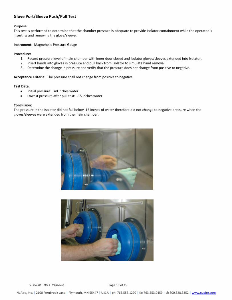
Glove Port/Sleeve Push/Pull Test Purpose: This test is performed to determine that the chamber pressure is adequate to provide Isolator containment while the operator is inserting and removing the glove/sleeve. Instrument: Magnehelic Pressure Gauge Procedure:
1. Record pressure level of main chamber with inner door closed and Isolator gloves/sleeves extended into Isolator. 2. Insert hands into gloves in pressure and pull back from Isolator to simulate hand removal. 3. Determine the change in pressure and verify that the pressure does not change from positive to negative.
Acceptance Criteria: The pressure shall not change from positive to negative. Test Data:
Initial pressure: .40 inches water
Lowest pressure after pull test: .15 inches water Conclusion: The pressure in the Isolator did not fall below .15 inches of water therefore did not change to negative pressure when the gloves/sleeves were extended from the main chamber.

GTB0150 | Rev 5 May/2014 Page 19 of 19
NuAire, Inc. | 2100 Fernbrook Lane | Plymouth, MN 55447 | U.S.A | ph: 763.553.1270 | fx: 763.553.0459 | tf: 800.328.3352 | www.nuaire.com
Interchange Particle Purge Time Determination Test (REF. CETA CAG‐002, 2.13) Purpose: This test is performed to determine the amount of time it takes the interchange chamber to recover to ISO Class 5 at 0.5 micron particle levels after placing materials into the interchange chamber prior to transfer into main chamber. Instrument:
Met One Laser Particle Counter Model A2408
Clock w/second hand Procedure:
1. Verify the background count in the testing room is at least 100,000 (ppcf) (3,532,000 particles per cubic meter (ppcm)). 2. If the count is too low, elevate the background levels using an aerosol generator. 3. Place interchange counter isokinetic probe in the geometric center of the interchange chamber at a height of 6 inches. 4. Set the particle counter sample time to 3 second sample periods in “Concentration” mode to report ppcf. 5. Open exterior interchange door and place a transfer basket on the interchange worksurface. 6. Close exterior interchange door and initiate particle counter and clock. 7. Concentration levels are achieved when three consecutive counts are at or below 100 ppcf. 8. Record purge time as determined from initiation of particle counter to where maintained particle levels are achieved.
Acceptance Criteria: Particle concentration levels to be at or below 100 ppcf in less than 30 seconds. Test Data: Room background particle count: > 100,000 ppcf
Test #1 Test #2 Test #3 4 0 2 Conclusion: All particle concentration levels were reduced to ISO Class 5 at 0.5 micron conditions well within the 30 seconds. In addition, the interchange chamber being slightly less positive than the main chamber will always assure that no contamination will ever enter the main chamber through the Isolator airflow.