Embed Size (px)
Citation preview

052522-002r13 Printed in USA November, 2018
INSTALLATION MANUAL APEX
with Direct Response Electronics RV
Read this manual before installing or servicing this product. Failure to follow the instructions and safety precautions in this manual can result in personal injury and/or cause the product to not operate properly.
TABLE OF CONTENTS Product Overview .......................................................................................................................... 1
Apex Patio Awning Specifications .................................................................................................. 1 Component Checklist.............................................................................................................................. 2
Installation – Mechanical .............................................................................................................. 4 Required Pre-Installation Parameters ..................................................................................................... 4 Mounting Plate Layout and Installation ................................................................................................... 4 Mounting the Awning Unit ....................................................................................................................... 5
Installation – Electrical .................................................................................................................. 6 Control Panel Installation - Key Pad ....................................................................................................... 6 Control Box Installation ........................................................................................................................... 7
Installing the Remote Receiver....................................................................................................... 8 Programming the Remote Receiver ....................................................................................... 8 Operational Notes: ................................................................................................................. 8
Ignition Lockout Sensor Installation (Optional) ............................................................................... 9 Wiring Diagram – Single Awning .......................................................................................................... 10 Wiring Diagram – 2-Awnings ................................................................................................................ 11 Wiring Diagram – 4 Awnings ................................................................................................................ 13 Connection Flex w/ "110VDR" Control Boxes ...................................................................................... 15 Optional Manual Bypass Switch ........................................................................................................... 15 Optional LED Lighting Switch Installation ............................................................................................. 16
Standard System Adjustments .................................................................................................. 17 Adjusting the Pitch ................................................................................................................................ 17 Setting the Motor Limits ........................................................................................................................ 18
Adjusting the OUT Limit Switch .................................................................................................... 18 Adjusting the IN Limit Switch ........................................................................................................ 18
Manual Override ................................................................................................................................... 19
PROPRIETARY STATEMENT The Apex Patio Awning is a product of Carefree of Colorado, located in Broomfield, Colorado, USA. The information contained in or disclosed in this document is considered proprietary to Carefree of Colorado. Every effort has been made to ensure that the information presented in the document is accurate and complete. However, Carefree of Colorado assumes no liability for errors or for any damages that result from the use of this document.
The information contained in this manual pertains to the current configuration of the models listed on the title page. Earlier model configurations may differ from the information given. Carefree of Colorado reserves the right to cancel, change, alter or add any parts and assemblies, described in this manual, without prior notice.
Carefree of Colorado agrees to allow the reproduction of this document for use with Carefree of Colorado products only. Any other reproduction or translation of this document in whole or part is strictly prohibited without prior written approval from Carefree of Colorado.
SAFETY INFORMATION
This is the safety alert symbol. It is used to alert individuals to potential personal injury hazards. Obey all safety messages that follow this symbol to avoid possible personal injury or death.
WARNING Indicates a hazardous situation, which if not avoided, could result in death or serious bodily injury.
CAUTION Indicates a hazardous situation, which if not avoided, may result in minor or moderate bodily injury.
NOTICE Indicates a situation that may result in equipment-related damage.
General Safety:
WARNING This product can expose you to chemicals including Di-isodecyl phthalate (DIDP), Vinyl Chloride and Formaldehyde, which are known to the state of California to cause cancer or birth defects or other reproductive harm. For more information visit www.P65warnings.ca.gov
WARNING Shock Hazard. Always disconnect battery or power source before working on or around the electrical system.
WARNING Always wear appropriate safety equipment (i.e. goggles).
CAUTION Always use appropriate lifting devices and/or helpers when lifting or
holding heavy objects.
NOTICE When using fasteners, do not over tighten. Soft materials such as fiberglass and
aluminum can be "stripped out" and lose the ability to grip and hold.
Carefree of Colorado www.carefreeofcolorado.com a Scott Fetzer company
Electric components in this product have been tested by the following agencies:
Motor: UL Recogonized (USA)
CSA Approved (Canada)
Controls: UL Listed (USA & Canada)
Carefree of Colorado Installation Manual APEX
522522-002r13 1
PRODUCT OVERVIEW The Apex Patio Awning offers the coach owner an awning system that provides as much or as little shade as required. The canopies are housed in an aluminum case that easily blends in with the coach roof. The awning extends to a maximum of 10 feet from the side wall. The canopy is made from Acrylic fabric.
Each unit is equipped with lateral support arms that are the strongest available on the market. No vertical arms interfere with coach sidewalls or equipment that may be mounted on the roof. These arms can also be adjusted to vary the canopy pitch up to 3 feet (it is strongly recommended that service and adjustments be performed by trained technicians).
The unique and innovative 110V electronic control system provides Carefree’s Direct Response system with interior touch pad controls for standard extend/retract functions. At the master control panel the auto-retract system can be engaged to automatically retract the awnings in windy conditions with sensitivity, set by the user, to respond to a variety of wind speed conditions. An RF remote is furnished with the Direct Response system.
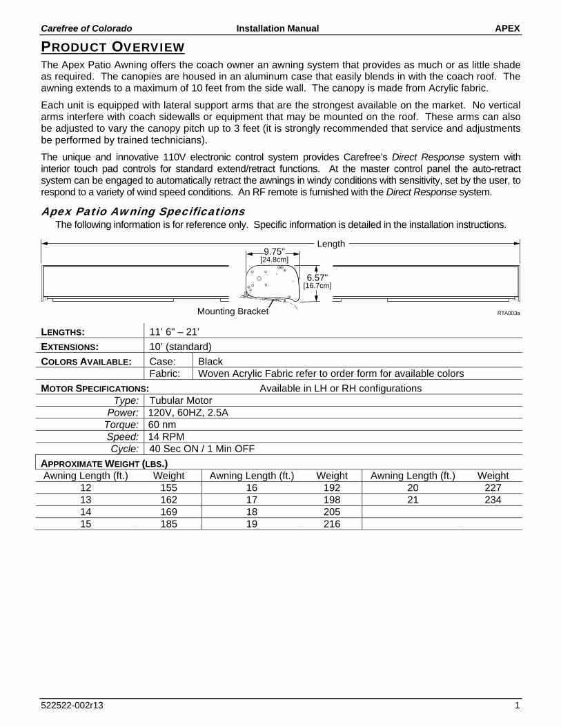
Apex Patio Awning Specifications The following information is for reference only. Specific information is detailed in the installation instructions.
LENGTHS: 11’ 6" – 21’
EXTENSIONS: 10’ (standard)
COLORS AVAILABLE: Case: Black Fabric: Woven Acrylic Fabric refer to order form for available colors
MOTOR SPECIFICATIONS: Available in LH or RH configurations Type: Tubular Motor
Power: 120V, 60HZ, 2.5A Torque: 60 nm Speed: 14 RPM Cycle: 40 Sec ON / 1 Min OFF
APPROXIMATE WEIGHT (LBS.) Awning Length (ft.) Weight Awning Length (ft.) Weight Awning Length (ft.) Weight
12 155 16 192 20 227 13 162 17 198 21 234 14 169 18 205 15 185 19 216
Length
RTA003aMounting Bracket
6.57"[16.7cm]
9.75"[24.8cm]

APEX Installation Manual Carefree of Colorado
2 052522-002r13
COMPONENT CHECKLIST
RTA032b
Single Awning
Dual Awning
4-Awning
3 4 5
7
61
2
11
9 10
12 13
14 15 16 17
18
19
20
21 22
8
PowerOn/Off Stop
Motion SensorLow High
Awning ControlExtend Retract
All Awnings
Awning 2
Awning 1
Extend Retract
PowerOn/Off
Awning 4
Motion SensorLow High
Stop
Awning 1
Awning 2
Awning 3
Extend Retract
All Awnings
Driver Side
Passenger Side
Power On/Off
Motion SensorLow High
Awning Control
Extend
Retract
Stop
23

Carefree of Colorado Installation Manual APEX
522522-002r13 3
ITEM DESCRIPTION QTY NOTE
1 Apex Awning Assembly 1 1 2 Mounting Bracket (Note) 2 3 Screw, Rolock, Thread Cutting 3/8 x 1 1/2 (Note) 3 4 Screw, Lag 3/8 x 3 (Note) 3 5 Screw, Hex Head 5/16-18 x 2 (Note) 3 6 Square Nut 5/16-18 (Note) 3 7 Hex Key 7mm x 133mm 1 8 Control Box Single Awning 1 4 9 Key Pad Assy Single Awning 1 4,5 10 Remote Control Key FOB, 433MHz Single Awning 1 6 11 Control Box Dual Awning 1 4 12 Key Pad Dual Awning 1 4,5 13 Remote w/ stop, 433 MHz Dual Awning 1 4,6 14 Control Box 1 (Motor #1, Motor #2) 4-Awning Combo 1 4 15 Control Box 2 (Motor #3, Motor #4) 4-Awning Combo 1 4 16 Key Pad 4-Awning Combo 1 4,5 17 Remote w/ stop, 433 MHz 4-Awning Combo 1 4,6 18 RF Receiver, 433 MHz 1 19 RJ11 Cable 60 inches 1 7 20 RJ11 Cable 240 inches 1 9 21 Sensor, Ignition Lock-Out 1 7,8 22 Splitter 1 7,8 23 Coupler, Cable 1 9 Notes: 1. Awning configuration is specified at time of order, including awning length, LH or RH configuration,
fabric color etc. Check awning assembly against original purchase order. 2. Item 2 Mounting Plates: Quantity of 3 per awning 18'-11" or less
Quantity of 4 per awning 19' or longer Some Original Equipment Manufacturer (OEM) installations may specify a different quantity.
3. Mounting screws (item 3 or 4) for the mounting plates = 6 per mounting plate Securing screw (item 5) and nut (item 6) = 1 each per mounting plate. See note 2.
4. Electronic components are not interchangeable between systems. 5. Mounting screws are included with switches and mounting plates. 6. Additional remotes can be ordered separately. 7. 60" cable (item 19) is furnished with items 9a, 18 and 21, one additional cable is furnished with the 4-
awning control boxes (items 14, 15). 8. The optional ignition lockout and splitter (items 21, 22) must be ordered separately. Two versions of
the lockout sensor are available; refer to page 9 for description. 9. Long cable (item 20) and /or coupler (item 23) are specified at time of order.
APEX Installation Manual Carefree of Colorado
4 052522-002r13
INSTALLATION – MECHANICAL The following instructions are for the physical installation of one Apex awning. Repeat the instructions for each awning to be installed.
REQUIRED PRE-INSTALLATION PARAMETERS Prior to installing the awning system, the installer must determine the layout of the system and provide specific construction elements to successfully assemble the awning components.
1. Determine the location, size and type of awning to be mounted. There must be structure at the awning mount locations. Fiberglass or sheet metal alone is NOT
strong enough to support the weight of the awning!
WARNING The Apex awning has significant weight. The awning and attaching brackets must be securely attached to the structural frame of the roof. Consult the coach manufacturer to determine the type and position of the roof's structural members and the structure's ability to support the weight. Failure to heed this warning can result in serious injury and property damage
2. Determine the mounting locations for the control box and switch assemblies. For 110VAC installations, the installer must provide enclosed junction boxes for all wire splices. Boxes are
required in conformance with prevailing construction codes.
At the control box location, AC input is required. It is recommended that the installer provide a dedicated AC circuit for the awning system that is protected by an appropriate sized fuse/circuit breaker. Each patio awning draws a maximum of 3 amps.
The motion sensor for the Direct Response system is mounted on the lead rail of the patio awning. 10 feet cable is available from the awning mount position, and will require a routing path to the control box. If the control box is located at a distance greater than 10 feet, the installer must provide a terminated jumper cable from the box location to the cable end.
CAUTION The Apex awning is extremely heavy. Moving and/or lifting the awning
requires a minimum of 3 people. The use of a lifting device is strongly recommended.
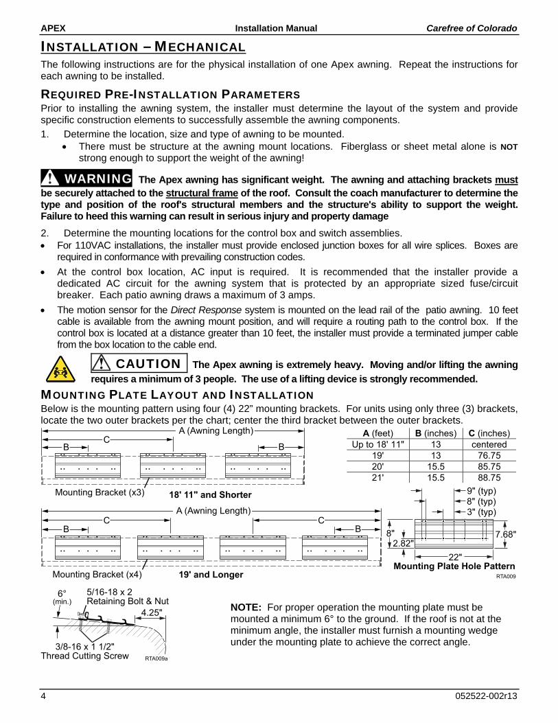
MOUNTING PLATE LAYOUT AND INSTALLATION Below is the mounting pattern using four (4) 22” mounting brackets. For units using only three (3) brackets, locate the two outer brackets per the chart; center the third bracket between the outer brackets.
NOTE: For proper operation the mounting plate must be mounted a minimum 6° to the ground. If the roof is not at the minimum angle, the installer must furnish a mounting wedge under the mounting plate to achieve the correct angle.
19' and Longer RTA009
3" (typ)8" (typ)9" (typ)
8"2.82"
7.68"
22"Mounting Plate Hole Pattern
A (Awning Length)
B BC
Mounting Bracket (x3)
A (Awning Length)
B BC C
Mounting Bracket (x4)
18' 11" and Shorter
A (feet) B (inches) C (inches)
Up to 18' 11" 13 centered
19' 13 76.75
20' 15.5 85.75
21' 15.5 88.75
RTA009a
4.25"
3/8-16 x 1 1/2"Thread Cutting Screw
5/16-18 x 2Retaining Bolt & Nut
6°(min.)

Carefree of Colorado Installation Manual APEX
522522-002r13 5
1. Determine the location of the awning mounts:
1.1 Mounting area must be flat and clear of obstacles,
1.2 The awnings have appreciable weight; the mounting screws MUST fasten into the structure.
2. Position the mounting plates on the coach roof. Horizontally position the plates using the dimensions in the chart.
NOTE: Two types of attaching screws are included in the kit. The 3/8” rolock screws are for attaching into metal structure. The 3/8” lag screws should be used for attaching into wood structures.
3. For rolock thread cutting screws:
3.1 For each plate, on one end of the plate, use the plate as a template and drill an 11/32” pilot hole into the structure. Attach the plate using a 3/8-16 x 1 1/2 thread cutting screw.
3.2 Confirm position of plate and repeat step 6 on the opposite end of the mounting plate.
3.3 Continue to drill and attach using the 3/8-16 x 1 1/2 thread cutting screws. Use six (6) screws minimum per plate.
4. For lag screws:
4.1 For each plate, on one end of the plate, use the plate as a template and drill a 3/16” pilot hole into the structure. Attach the plate using a 3/8 x 3 lag screw.
4.2 Confirm position of plate and repeat step 6 on the opposite end of the mounting plate.
4.3 Continue to drill and attach using the 3/8 x 3 lag screws. Use six (6) screws minimum per plate.
5. In the rear track of each mounting plate, start one (1) 5/16-18 x 2 screw and square nut through hole in back of mounting plate. Do not tighten at this time.
6. At the motor location, drill one (1) 1/2” hole through outer surface. The position may be under or behind the end cap position.
MOUNTING THE AWNING UNIT 1. While lifting the awning, route the awning motor
wires through the 1/2” hole drilled previously.
NOTE: It is necessary to first insert the sensor cable and connector through the hole then insert the motor wires.
2. Set the awning into the hooks of the mounting bracket. Pull the case forward to fully engage the bracket.
3. Adjust the horizontal position of the awning as required.
4. Tighten the securing bolts. Torque to 10 ft-lbs.
5. Seal the wires and access hole with a quality silicone sealant.
Mounting Bracket (ref)
Securing Bolt
RTA004
Awning Frame (ref)

APEX Installation Manual Carefree of Colorado
6 052522-002r13
INSTALLATION – ELECTRICAL
WARNING Shock Hazard. Always disconnect battery or power source before working on or around the electrical system.
IMPORTANT NOTICES: Failure to follow the wiring instructions in this publication may void the warranty.
All wiring must conform to NEC (National Electrical Code) and local codes.
DO NOT wire two or more motors to one motor controller.
The SO cable from the 110VAC awning motor can only pass directly through a wall, it can not be laid up in the wall and must be connected to NM wire or individual wires in conduit no more than 6 inches past the point of entry.
The installer must provide enclosed junction boxes for all 110VAC wire splices. Boxes are required in conformance with prevailing construction codes. Installers are required to furnish the UL approved electrical boxes where required.
At the control box location, AC input is required. It is recommended that the installer provide a dedicated AC circuit for the awning system that is protected by an appropriate sized fuse/circuit breaker. Each patio awning draws a maximum of 3 amps.
The motion sensor for the Direct Response system is mounted on the patio awning. 10 feet cable is available from the awning wall mount, and will require a routing path to the control box. If the control box is located at a distance greater than 10 feet, the installer must provide a terminated jumper cable from the box location to the cable end.
Terminated cable is a 4-wire RJ11 terminated phone cord (straight, no twist).
NOTE: Cable lengths of the furnished cables are listed in the chart with the system wiring diagram. If a connection requires a length greater than the supplied cable, the installer must provide a terminated jumper cable from the box location to the cable end. Terminated cables are 4-wire RJ11 terminated phone cord (straight, no twist).
KEY PAD INSTALLATION 1. Locate the mounting location of the key pad. The key pad
requires a flat area approximately 2 3/4" wide by 4 1/2" tall.
2. Use the mounting plate as a template and mark the location of the two mounting holes.
3. Remove the plate, mark and cut a 1" hole in the position shown.
4. Mount the plate to the surface using the included screws.
5. Route the 25 foot RJ11 cable from the control box location through the wall and mounting plate.
6. Attach the cable to the back of the key pad then attach the key pad to the mounting plate.
NOTE: The key pad attaches to the plate with magnetic latches. No additional attaching hardware is required.
1.25”
O 1” min.
O .125” Pilot Hole(2 plcs)
RJ11 Cable
Mounting Plate
Key Pad
Paramount005
4.5”
3.25”(ref)
2.75”
BlackRedGreen
Black
Yellow
RedGreen
Yellow
Cables are 4-wire RJ11terminated phone cord(straight, no twist).
RTA031
Carefree of Colorado Installation Manual APEX
522522-002r13 7
CONTROL BOX INSTALLATION NOTES: a) For Multiple Awing Installations: The awning motor that is connected to the controller board marked "motor
#1" will correspond with "Awning 1" on the touch pad control and remote. The awning motor connected to "motor #2" will correspond with "Awning 2" on the controls etc.
b) For 4-Awning Installations: Awnings connected to motor #1 & #2 correspond to "Passenger Side Awnings", awnings connected to motor #3 & #4 correspond to "Driver Side Awnings".
c) The control boxes are not suitable for exterior installations and must be mounted in the INTERIOR of the vehicle.
For Single Awning installations: refer to wiring diagram on page 10.
For 2-Awning installations: refer to wiring diagram on page 11.
For 4-Awning installations: refer to wiring diagram on page 13.
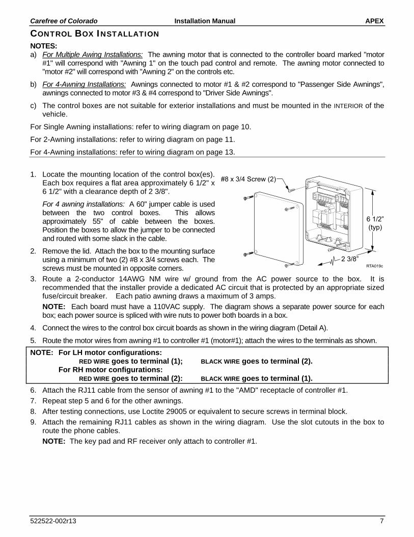
1. Locate the mounting location of the control box(es). Each box requires a flat area approximately 6 1/2" x 6 1/2" with a clearance depth of 2 3/8".
For 4 awning installations: A 60" jumper cable is used between the two control boxes. This allows approximately 55" of cable between the boxes. Position the boxes to allow the jumper to be connected and routed with some slack in the cable.
2. Remove the lid. Attach the box to the mounting surface using a minimum of two (2) #8 x 3/4 screws each. The screws must be mounted in opposite corners.
3. Route a 2-conductor 14AWG NM wire w/ ground from the AC power source to the box. It is recommended that the installer provide a dedicated AC circuit that is protected by an appropriate sized fuse/circuit breaker. Each patio awning draws a maximum of 3 amps.
NOTE: Each board must have a 110VAC supply. The diagram shows a separate power source for each box; each power source is spliced with wire nuts to power both boards in a box.
4. Connect the wires to the control box circuit boards as shown in the wiring diagram (Detail A).
5. Route the motor wires from awning #1 to controller #1 (motor#1); attach the wires to the terminals as shown.
NOTE: For LH motor configurations: RED WIRE goes to terminal (1); BLACK WIRE goes to terminal (2). For RH motor configurations: RED WIRE goes to terminal (2): BLACK WIRE goes to terminal (1).
6. Attach the RJ11 cable from the sensor of awning #1 to the "AMD" receptacle of controller #1.
7. Repeat step 5 and 6 for the other awnings.
8. After testing connections, use Loctite 29005 or equivalent to secure screws in terminal block.
9. Attach the remaining RJ11 cables as shown in the wiring diagram. Use the slot cutouts in the box to route the phone cables.
NOTE: The key pad and RF receiver only attach to controller #1.
#8 x 3/4 Screw (2)
RTA019c
6 1/2”
(typ)
2 3/8”

APEX Installation Manual Carefree of Colorado
8 052522-002r13
INSTALLING THE REMOTE RECEIVER 1. Determine the location of the RF receiver:
1.1 Do not mount the unit near heat producing elements such as LP appliances or engine exhaust components.
1.2 For best reception, do not mount the unit near or on a metal surface.
1.3 Mount the unit with the antenna pointing up.
1.4 The included cable is approximately 60 inches long. Mount the unit close enough to the splitter or control box so that the cord can be connected without stressing the connections.
1.5 Allow adequate room below the box to access the connector jack, programming button and indicator light.
2. Position the control box and secure using two (2) #6 x 1/2” screws.
NOTE: If the box is mounted on a surface that is less that 1/2” thick, the screws will protrude through the opposite side of the surface.
3. Connect the cable to the receiver.
4. Route the cable to the splitter; or, to the control box and connect to “EYE”.
PROGRAMMING THE REMOTE RECEIVER These instructions apply to the current 433 MHz configuration of the remote and receiver (RR version 2). For older versions refer to the Apex Service Manual listed on the inside of the front cover.
1. Power to the control box must be on.
2. Press and release the “Press to Learn Transmitter” button on the bottom of the receiver box. The receiver is in program mode when the red light comes on.
3. Press and release the stop button on the remote. The red light will go out after the receiver learns the remote signal.
NOTE: For single awning key FOB remotes: Pressing the stop button will cause the blue up arrow button to default as the open (extend) function. If a function button is pressed to train the receiver, it will be programmed as the open (extend) button. Example: Pressing the bottom button will program the bottom button for extend and the top button as retract.
4. Repeat for each additional remote.
OPERATIONAL NOTES: Transmitter and receiver operate on a frequency of 433 MHz.
The receiver exits the program mode after ten seconds.
If the light does not come on above, the memory is full and must be cleared. If the light still does not come on, check the continuity of the cord between the boxes and repair or replace as required. Pin 1 of the 1st connector goes to pin 1 of the 2nd connector etc.
If the light does not go out in above, the receiver already knows the transmitter's signal or the battery in the remote needs to be replaced.
To clear the memory: PRESS AND HOLD the transmitter learn button. While holding the button, the indicator light should be OFF for the full 5 seconds then come on.
The system may be programmed for up to 5 remotes. Additional remotes may be ordered separately.
DR020
TO
EY
E P
OR
Ton R
P24
Pro
gra
mM
ode
Pre
ss to L
earn
Tra
nsm
itte
r
UP
ProgramButton
IndicatorLight
RTA034
1”
TO
EY
E P
OR
Ton R
P24
Pro
gra
mM
od
e
Pre
ss to L
earn
Tra
nsm
itte
r
UP
3 7/8”
4 3/16”
#6 x 1/2Screw (2)

Carefree of Colorado Installation Manual APEX
522522-002r13 9
IGNITION LOCKOUT SENSOR INSTALLATION (OPTIONAL) Two ignition lockout sensors are available with the Direct Response System.
The STD ignition lockout module disables the extend function when the module receives a current through a switched 12VDC circuit..
The RTL ignition lockout module will fully retract the awning and disable the extend function when the module receives a current through a switched 12VDC circuit.
A switched 12VDC source is a line that is "hot" when the ignition switch is in the on position; or, a 12VDC circuit through a relay that is "hot" when a specific condition is met (i.e. releasing the parking brake). Relays are not furnished.
1. Disconnect power to the awning. Shut off the power source or pull the appropriate circuit breaker.
2. Locate the control box for the Direct Response System.
3. Open the cover of the control box.
4. For Single Awning Applications: 4.1. Disconnect the remote receiver cable from the "EYE" port in the control box. Do not disconnect the
cable from the receiver box.
4.2. Connect the supplied 6" cable to “EYE” port in the control box.
4.3. Attach the splitter to the other end of the cable.
4.4. Plug the cable from the remote receiver into the splitter.
4.5. Attach the Lock-Out Sensor to the end of the 60" cable. Route the cable as desired and connect the cable to the splitter.
4.6. Proceed to step 6.
5. For Multiple Awning Applications: 5.1. The module may be connected to the control box as described for single awning applications.
OR
5.2. The module may be directly connected to any open "EYE" port on any of the control boards. It is not necessary to use the short cable or splitter.
5.3. Proceed to step 6.
NOTE: Wires to the module are not pin specific.
6. Attach one 18-gauge wire to a terminal of the sensor and route the wire to a suitable 12VDC ground.
7. Attach a second 18-gauge wire to the second terminal of the sensor and route the wire to a SWITCHED 12VDC source.
8. Bundle and secure the sensor, cable and wires as required.
9. Reattach the control box cover.

APEX Installation Manual Carefree of Colorado
10 052522-002r13
WIRING DIAGRAM – SINGLE AWNING
FROM TO (RH CONFIGURATION) TO (LH CONFIGURATION) Motor Black Control Box 1 Control Box 2
Red 2 1 White 3 3 Ground 6 6
AC Power Source
White Control Box 4 Control Box 4 Black 5 5 Ground 7 7
Awning Sensor 10’ Cable Control Box “AMD” Control Box “AMD” Key Pad 60“ Cable Control Box “DSK” Control Box “DSK” Splitter 60" Cable Control Box "EYE" Control Box "EYE" RF Receiver 60” Cable Splitter Splitter Ignition Lockout 60“ Cable Splitter Splitter Notes: 1. Cable lengths are the lengths of the furnished cables. If a connection requires a length greater than the supplied cable, the
installer must provide a terminated jumper cable from the box location to the cable end.
TO
EY
E P
OR
To
n R
P2
4
Pro
gra
mM
od
e
Pre
ss t
o L
ea
rnT
ran
sm
itte
r
UP
RFReceiver
GRN
BLKWHT
RED
DR012
Ignition Switched+12VDC
12VDCGround
IgnitionLockoutSensor(Optional)
SplitterSe
nso
r
Key Pad
Awning3
5
4
2 C
on
du
cto
r 14
AW
G N
M W
ire w
/ Gn
d
To 110VAC
AM
DS
UN
AU
XE
YE
DS
KBLKWHT
RED
GRNgrn
whtblk
1
765432
1
765432
3 C
on
du
cto
r 14
AW
GN
M W
ire w
/ Gn
d
Sensor
Remote
RedBlackWhiteGreen (Ground)
1 Wire Legend:
2 For LH Motor Configurations: Motor Red goes to Pin (1); Motor Black goes to Pin (2)For RH Motor Configurations: Motor Red goes to Pin (2) Black; Motor Black goes to pin (1)
3 The SO cable from the 110VAC awning motor can only pass through a wall, it cannot be laid up in the walland must be connected to NM wire or individual wires in conduit no more than 6 inches past the point of entry.
NOTES:
4
Wires for the Ignition Lock-Out Sensor are not pin specific.5
Splitter is used only when Optional Lock-Out Sensor is installed. Connect RF Receiver directly to “EYE”if Lock-Out is not installed.
Detail AFor RH Configuration
Reverse Red & Black Wires
REDWHT
BLK
GRNgrn
whtblk
Key Pad
Rear ViewSwitch Panel
Patio
Wind Speed
RibbonCable
Detail BUsed thru 2006
PowerOn/Off
Retract
Stop
Extend
Auto-Retract
On/Off
High
Wind Speed
Low

Carefree of Colorado Installation Manual APEX
522522-002r13 11
WIRING DIAGRAM – 2-AWNINGS
TO
EY
E P
OR
Ton R
P24
Pro
gra
mM
od
e
Pre
ss to
Le
arn
Tra
nsm
itte
r
UP
RFReceiver
GRN
BLKWHT
RED
Key Pad
DR014
Ignition Switched+12VDC
12VDCGround
IgnitionLockoutSensor(Optional)
Splitter
Se
nso
r #1
Key PadS
en
so
r #2
Awning #13
5
4
REDWHT
BLK
GRN
BLKWHT
RED
GRN
WhtBlk
Grn
Wht Blk
Grn
2 C
on
du
cto
r 14
AW
G N
M W
ire w
/ Gnd
To 1
10V
AC
AM
DS
UN
AU
XE
YE
DS
K
AM
DS
UN
AU
XE
YE
DS
K
1
765432
1
7
6
5
4
3
2
1
7
6
5
4
3
2
3 Conductor 14AWGNM Wire w/ Gnd
Sensor
GRN
BLKWHT
RED Awning #2Sensor
Remote
3
3 Conductor 14AWGNM Wire w/ Gnd
DETAIL A110VAC Power Line In
BlackRedGreen
Black
Yellow
RedGreen
Yellow
Cables are 4-wire RJ11terminated phone cord(straight, no twist).
1
765432

APEX Installation Manual Carefree of Colorado
12 052522-002r13
NOTES:
Wire Legend
Awning #1shown as LH Motor, Awning #2shown as RH Motor
For LH Motor Configurations: Motor Red goes to Pin (1); Motor Black goes to Pin (2) For RH Motor Configurations: Motor Red goes to Pin (2); Motor Black goes to Pin (1)
The SO cable from the 110VAC awning motor can only pass directly through a wall; it cannot be laid up in the wall and must be connected to NM wire or individual wires in conduit no more than 6" past the point of entry.
Splitter is used only when Optional Lock-Out Sensor is installed. Connect RF receiver directly to "EYE" if Lock-Out is not installed.
Wires for Ignition Lock-Out Sensor are not pin specific.
For screw type terminals: After testing connections, use Loctite 29005 or equivalent to secure screws in terminal block
Cables are 4-wire RJ11 terminated phone cord (straight, no twist).
Terminal block designations are for reference only. Actual boards may not be marked.
TO CONTROL BOARD FROM MOTOR #1 MOTOR #2 AC Power Source White 4 4
Black 5 5 Ground 7 7
Awning #1 Motor Black Refer to Flag Note 2
Red White 3 Ground 6
Awning #2 Motor Black Refer to Flag Note 2
Red White 3 Ground 6
#1 Sensor 10’ Cable “AMD” #2 Sensor 10’ Cable “AMD” Key Pad 25' Cable "DSK" Splitter 60" Cable "EYE" RF Receiver 60” Cable Splitter Ignition Lockout 60“ Cable Splitter Notes: 1. Splitter is used w/ Ignition Lock-Out only. If Lock-Out is not installed, connect the receiver directly to "EYE".
2. Cable lengths are the lengths of the furnished cables. If a connection requires a length greater than the supplied cable, the installer must provide a terminated jumper cable from the box location to the cable end.
1
Green (Ground)White
RedBlack
2
3
4
5 Loctite 29005
Screw Type Terminal Block
6
7
8

Carefree of Colorado Installation Manual APEX
522522-002r13 13
WIRING DIAGRAM – 4 AWNINGS
TO
EY
E P
OR
To
n R
P2
4
Pro
gra
mM
od
e
Pre
ss to
Le
arn
Tra
nsm
itte
r
UP
RFReceiver
GRN
BLKWHT
RED
Key Pad
DR015
Ignition Switched+12VDC
12VDCGround
IgnitionLockoutSensor(Optional)
Splitter
Se
nso
r #1
Key Pad
Se
nso
r #2
Awning #13
5
4
REDWHT
BLK
GRN
BLKWHT
RED
GRN
WhtBlk
Grn
Wht Blk
Grn
2 C
on
du
cto
r 14
AW
G N
M W
ire w
/ Gnd
To 1
10V
AC
REDWHT
BLK
GRN
BLKWHT
RED
GRN
AM
DS
UN
AU
XE
YE
DS
K
AM
DS
UN
AU
XE
YE
DS
K
AM
DS
UN
AU
XE
YE
DS
K
AM
DS
UN
AU
XE
YE
DS
K
1
765432
1
765432
1
765432
1
7
6
5
4
3
2
1
7
6
5
4
3
2
To 1
10V
AC
3 Conductor 14AWGNM Wire w/ Gnd
To 1
10V
AC
Sensor
GRN
BLKWHT
RED Awning #2Sensor
Remote
3
3 Conductor 14AWGNM Wire w/ Gnd
GRN
BLKWHT
RED
Sensor #
3
Se
nso
r #4
Awning #33
3 Conductor 14AWGNM Wire w/ Gnd
Sensor
GRN
BLKWHT
RED Awning #4Sensor
3
3 Conductor 14AWGNM Wire w/ Gnd
DETAIL A110VAC Power Line In
(typical both boxes)
BlackRedGreen
Black
Yellow
RedGreen
Yellow
Cables are 4-wire RJ11terminated phone cord(straight, no twist).
1
765432

APEX Installation Manual Carefree of Colorado
14 052522-002r13
NOTES:
Wire Legend
Awnings #1 & #4 shown as LH Motor, Awnings #2 & #3 shown as RH Motor
For LH Motor Configurations: Motor Red goes to Pin (1); Motor Black goes to Pin (2) For RH Motor Configurations: Motor Red goes to Pin (2); Motor Black goes to Pin (1)
The SO cable from the 110VAC awning motor can only pass directly through a wall; it cannot be laid up in the wall and must be connected to NM wire or individual wires in conduit no more than 6" past the point of entry.
Splitter is used only when Optional Lock-Out Sensor is installed. Connect RF receiver directly to "EYE" if Lock-Out is not installed.
Wires for Ignition Lock-Out Sensor are not pin specific.
For screw type terminals: After testing connections, use Loctite 29005 or equivalent to secure screws in terminal block
Cables are 4-wire RJ11 terminated phone cord (straight, no twist).
Terminal block designations are for reference only. Actual boards may not be marked.
TO CONTROL BOARD FROM MOTOR #1 MOTOR #2 MOTOR #3 MOTOR #4 AC Power Source White 4 4 4 4
Black 5 5 5 5 Ground 7 7 7 7
Awning #1 Motor Black Refer to Flag Note 2
Red White 3 Ground 6
Awning #2 Motor Black Refer to Flag Note 2
Red White 3 Ground 6
Awning #3 Motor Black
Refer to Flag Note 2
Red White 3 Ground 6
Awning #4 Motor Black
Refer to Flag Note 2 Red
White 3 Ground 6
#1 Sensor 10’ Cable “AMD” #2 Sensor 10’ Cable “AMD” #3 Sensor 10’ Cable “AMD” #4 Sensor 10’ Cable “AMD” Key Pad 25' Cable "DSK" Splitter 60" Cable "EYE" RF Receiver 60” Cable Splitter Ignition Lockout 60“ Cable Splitter Notes: 1. Splitter is used w/ Ignition Lock-Out only. If Lock-Out is not installed, connect the receiver directly to "EYE".
2. Cable lengths are the lengths of the furnished cables. If a connection requires a length greater than the supplied cable, the installer must provide a terminated jumper cable from the box location to the cable end.
1
Green (Ground)White
RedBlack
2
3
4
5 Loctite 29005
Screw Type Terminal Block
6
7
8

Carefree of Colorado Installation Manual APEX
522522-002r13 15
CONNECTION FLEX W/ "110VDR" CONTROL BOXES The wiring diagrams show the standard installation for multiple awning configurations. For control boxes marked w/ "110VDR", the installer may adjust the cable interconnections for greater flexibility during installation.
1. The key pad may be installed in the unused DSK port of any board with the jumper cables sequentially connected from the AUX port to the DSK port of the next board.
Example: Placing the keypad in the DSK of Board 3.
2. The RF Receiver and the optional ignition lock-out can be plugged into any unused "EYE" port. It is not
necessary to use the splitter as shown in the diagrams.
3. The "110VDR" control boxes are compatible with integrator interfaces. Contact Carefree engineering for information and system requirements.
OPTIONAL MANUAL BYPASS SWITCH Installers may elect to install a manual bypass switch for testing or emergency operation of the awning. The simple switch allows the operator to extend or retract the awning without using the keypad control panel. For multiple awning installations, a separate switch must be installed for each awning.
1. Open the control box and identify the terminal block next to the phone cord jacks.
2. Connect the switch to the terminal block as shown in the diagram.
The switch is a single pole, double throw, momentary ON, center OFF. Components are installer furnished.
Key Pad
CR024
AMDSUNAUXEYEDSK AMDSUNAUXEYEDSK AMDSUNAUXEYEDSK AMDSUNAUXEYEDSK
Motor 1 Motor 2 Motor 3 Motor 4
Common
Extend
RetractManual SwitchSingle Pole, Double
Throw, Momentary ON,
Center OFF
DR011

APEX Installation Manual Carefree of Colorado
16 052522-002r13
OPTIONAL LED LIGHTING SWITCH INSTALLATION An optional factory installed LED light strip is available for the Apex awning. The strip is mounted in the lead rail; the harness is routed through the awning with the Direct Response cable.
For multiple awning installations, each LED strip may be attached to an individual switch or two LED strips can be hooked in parallel to a single switch.
NOTE: Installers may choose to furnish the control switch. The installation requires that the power line (+12VDC) be attached to a dedicated 2A circuit breaker or a 2A in-line fuse must be installed between the switch and power source. For easy access, locate the fuse close to the switch.
1. Route the harness into the vehicle with the Direct Response cable and the motor power cable.
2. Determine the location of the switch.
3. At the switch location, cut a 1 1/8" x 1 1/2" hole.
4. Wire the switch as shown below. Wire terminals at the switch are .187, 18-24 awg female disconnects.
NOTE: Allow adequate slack in the 12VDC power line so that the in-line fuse (installed in step 5) can be accessed from behind the switch.
5. Install the in-line fuse: 5.1. Near the switch, cut the red 12VDC power line to the switch. Do not strip the insulation.
5.2. Insert a wire end into one of the wire channels until it butts up against the stop.
5.3. Fold that half of the connector body over until the element contacts the wire. Use pliers to crimp the connector closed.
5.4. Repeat for the second wire end.
5.5. Slide the fuse into the fuse port. Ensure that is firmly seated.
6. Press the in-line fuse, wires and switch into the mounting hole. Secure the switch using two (2) #6 x 1/2" screws.
7. Snap the switch bezel over the switch frame.
Kit SR0101 is available from Carefree and includes switch, fuse holder and 2A fuse.
LED021
1st awning LED Strip
Vehicle Wall
Red
+12VDC
GND
Switch18awg Wire
(minimum)
Re
d
Bla
ck
2A In-line Fuse See Switch Detail
2nd awning LED Strip Re
d
Bla
ck
ON
OFF
2A In-line Fuse(+12VDC Line)
Red
+12VDC
Single Pole, Single Throw Switch18awg Wire
(minimum)
Red (from power harness)
18-24awgFemale Disconnect (x2)2A In-line Fuse
GND
Red
+12VDC
Lighted Single Throw Switch18awg Wire
(minimum)
Red (from power harness)
2A In-line Fuse
18-24awgFemale Disconnect (x2)
1.13"
1.5"
#6 x 1/2" Screw (x2)
LED Strip
Vehicle Wall
Red
+12VDC
GND
Switch18awg Wire
(minimum)
Re
d
Bla
ck
2A In-line Fuse See Switch Detail
Individual Awning
Double Awning

Carefree of Colorado Installation Manual APEX
522522-002r13 17
STANDARD SYSTEM ADJUSTMENTS ADJUSTING THE PITCH The awning is factory set with minimum pitch. The amount of adjustment for increasing pitch may be limited by the mounting height above a door opening. The diagram chart below provides the minimum distance required above an opening with a swing-out door or window when the awning is set at MINIMUM and MAXIMUM pitch:
Door Width 0” 12” 18” 24” 30” 36” A @ MINIMUM PITCH 1” 1.25” 1.5” 1.75” 2” 2.5” A @ MAXIMUM PITCH 1” 3.5” 5.25” 7” 8.75” 10.5” NOTE: 1. Minimum Height (A) is measured from the door opening to the bottom of the mounting plate. The
value given is a minimum requirement. 2. Dimensions are based on a 6° roof pitch
NOTICE During installation or when the pitch of the awning is adjusted, it is important that the
lead rail is parallel to the awning housing.
1. Extend the awning fully.
2. On one end, loosen the 6mm hex screw located on the spring arm knuckle.
3. SLIGHTLY loosen the 3/4” nut on the side of the knuckle.
4. Turn the 3/4” adjustment nut located on the bottom of the knuckle. CLOCKWISE raises the pitch, COUNTERCLOCKWISE lowers the pitch.
NOTE: When raising the pitch, it is helpful to have a second person lift up on the lead rail.
5. Repeat steps 2 through 4 for the other end.
6. When the pitch adjustments are completed, tighten the 6mm screw and the 3/4” nut on the side of the knuckle.
When the pitch is adjusted, it is necessary to adjust the angle of the lead rail for the awning to close correctly. (refer to Detail B)
7. SLIGHTLY loosen the 3/4” nut on the side of each arm knuckle on the lead rail.
8. Turn the INSIDE 6mm hex screws of each knuckle to increase or decrease the angle of the lead rail. The bottom of the lead rail should be parallel with the ground.
9. When the lead rail adjustments are completed, tighten the 3/4” nut on the side of the knuckles.
A
Pitch
Width of Open Door RTA012
3/4” Adjustment Nut
6mm Hex Screw
RTA013
3/4” NutOn Side of Knuckle
Lead Rail (ref)
6mm Hex Screw
3/4” Nut
DETAIL A
DETAIL B
APEX Installation Manual Carefree of Colorado
18 052522-002r13
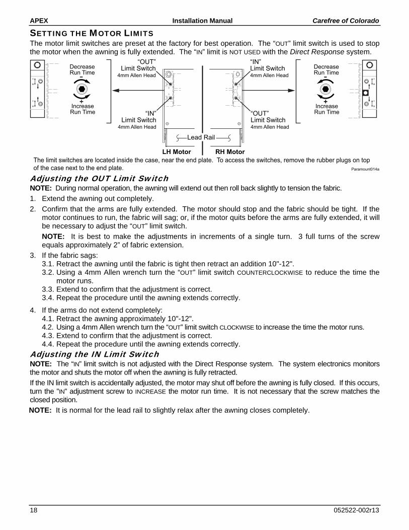
SETTING THE MOTOR LIMITS The motor limit switches are preset at the factory for best operation. The “OUT” limit switch is used to stop the motor when the awning is fully extended. The “IN” limit is NOT USED with the Direct Response system.
Adjusting the OUT Limit Switch NOTE: During normal operation, the awning will extend out then roll back slightly to tension the fabric.
1. Extend the awning out completely.
2. Confirm that the arms are fully extended. The motor should stop and the fabric should be tight. If the motor continues to run, the fabric will sag; or, if the motor quits before the arms are fully extended, it will be necessary to adjust the “OUT” limit switch.
NOTE: It is best to make the adjustments in increments of a single turn. 3 full turns of the screw equals approximately 2” of fabric extension.
3. If the fabric sags: 3.1. Retract the awning until the fabric is tight then retract an addition 10"-12". 3.2. Using a 4mm Allen wrench turn the “OUT” limit switch COUNTERCLOCKWISE to reduce the time the
motor runs. 3.3. Extend to confirm that the adjustment is correct. 3.4. Repeat the procedure until the awning extends correctly.
4. If the arms do not extend completely: 4.1. Retract the awning approximately 10"-12". 4.2. Using a 4mm Allen wrench turn the “OUT” limit switch CLOCKWISE to increase the time the motor runs. 4.3. Extend to confirm that the adjustment is correct. 4.4. Repeat the procedure until the awning extends correctly.
Adjusting the IN Limit Switch NOTE: The “IN” limit switch is not adjusted with the Direct Response system. The system electronics monitors the motor and shuts the motor off when the awning is fully retracted.
If the IN limit switch is accidentally adjusted, the motor may shut off before the awning is fully closed. If this occurs, turn the "IN" adjustment screw to INCREASE the motor run time. It is not necessary that the screw matches the closed position.
NOTE: It is normal for the lead rail to slightly relax after the awning closes completely.
The limit switches are located inside the case, near the end plate. To access the switches, remove the rubber plugs on top
of the case next to the end plate. Paramount014a
“IN”Limit Switch4mm Allen Head
“OUT”Limit Switch4mm Allen Head
LH Motor RH Motor
Lead Rail
“IN”Limit Switch
4mm Allen Head
“OUT”Limit Switch
4mm Allen Head
DecreaseRun Time
IncreaseRun Time
DecreaseRun Time
IncreaseRun Time

Carefree of Colorado Installation Manual APEX
522522-002r13 19
MANUAL OVERRIDE If 110V power is not available to the coach, the Apex awning can still be safely retracted using the manual override.
1. The bypass is located inside the case, near the end cap. Remove the large rubber plug located toward the rear of the case on the motor side of the awning.
2. Chuck the 7mm hex key into a 3/8” battery powered drill.
3. Insert the hex key into the manual override on the awning.
4. Operate the drill in the direction shown in the diagram to close the awning. Reverse the drill to open the awning.
5. When done, reinsert the rubber plug.
7mm HexManualOverride
RTA015aLH Motor RH Motor
Lead Rail
Open
Close
Open
Close