Embed Size (px)
DESCRIPTION
Cisco NSS Admin Guide
Citation preview

Cisco Small Business
NSS300 Series Smart Storage
ADMINISTRATION GUIDE

© 2011 Cisco Systems, Inc. All rights reserved. OL-21155-04
CCDE, CCENT, CCSI, Cisco Eos, Cisco Explorer, Cisco HealthPresence, Cisco IronPort, the Cisco logo, Cisco Nurse Connect, Cisco Pulse, Cisco SensorBase, Cisco StackPower,Cisco StadiumVision, Cisco TelePresence, Cisco TrustSec, Cisco Unified Computing System, Cisco WebEx, DCE, Flip Channels, Flip for Good, Flip Mino, Flipshare (Design), FlipUltra, Flip Video, Flip Video (Design), Instant Broadband, and Welcome to the Human Network are trademarks; Changing the Way We Work, Live, Play, and Learn, Cisco Capital,Cisco Capital (Design), Cisco:Financed (Stylized), Cisco Store, Flip Gift Card, and One Million Acts of Green are service marks; and Access Registrar, Aironet, AllTouch, AsyncOS,Bringing the Meeting To You, Catalyst, CCDA, CCDP, CCIE, CCIP, CCNA, CCNP, CCSP, CCVP, Cisco, the Cisco Certified Internetwork Expert logo, Cisco IOS, Cisco Lumin,Cisco Nexus, Cisco Press, Cisco Systems, Cisco Systems Capital, the Cisco Systems logo, Cisco Unity, Collaboration Without Limitation, Continuum, EtherFast, EtherSwitch, EventCenter, Explorer, Follow Me Browsing, GainMaker, iLYNX, IOS, iPhone, IronPort, the IronPort logo, Laser Link, LightStream, Linksys, MeetingPlace, MeetingPlace Chime Sound,MGX, Networkers, Networking Academy, PCNow, PIX, PowerKEY, PowerPanels, PowerTV, PowerTV (Design), PowerVu, Prisma, ProConnect, ROSA, SenderBase, SMARTnet,Spectrum Expert, StackWise, WebEx, and the WebEx logo are registered trademarks of Cisco and/or its affiliates in the United States and certain other countries.
All other trademarks mentioned in this document or website are the property of their respective owners. The use of the word partner does not imply a partnership relationship betweenCisco and any other company. (1002R)

Contents
Chapter 1: Introducing the NAS 8
Benefits 8
Logging In to the NAS 9
Using the Help 10
Approved Vendor List for Drives and UPS Compatibility 10
Chapter 2: Getting Started 11
Before You Begin 11
Getting to Know the NSS300 Series Smart Storage 12
NSS322 12
NSS324 and NSS326 15
Installing the NSS322, NSS324, and NSS326 19
Placement Tips 19
Installing the Disk Drives 19
Locking and Unlocking the Disk Trays 22
Connecting the Equipment 23
Verifying the Hardware Installation 24
Starting NAS Configuration 24
Windows Operating System 25
Mac OS X or Linux Operating System 25
System Configuration Using the Windows Setup Wizard 25
System Configuration Using the LCD Display 30
System Configuration Using Mac OS X or Linux 32
Mapping a Network Drive 33
Mapping a Network Drive from the Setup Wizard 33
Mapping a Network Drive From Windows 34
Installing the Client Utility for Windows 35
Install the Tool 35
Run the Tool From the CD 36
Remove the Tool 37
Installing the Client Utility for Mac 37
Cisco Small Business NSS300 Series Smart Storage Administration Guide 3

Contents
Accessing the Management GUI Using a Web Browser 38
Suggested Next Steps 38
Set Up Services 38
Set Up Backup 39
Set Up Network Shares 39
Reset Network Settings and Password 39
Inline Power Switch Module 40
Chapter 3: Managing the System 42
Status 42
System Information 43
System Service 44
Resource Monitor 47
View Logs 48
Administration 51
General Settings 51
Network 58
Hardware 67
Security 69
Notification 74
Power Management 79
Network Recycle Bin 81
Backup/Restore Settings 83
System Logs Settings 84
Firmware Upgrade 92
Restore to Factory Default 93
Network Service Discovery 94
Users 97
User Groups 102
Disk Management 105
Volume Management 105
RAID Management 111
Cisco Small Business NSS300 Series Smart Storage Administration Guide 4

Contents
HDD SMART 115
Encrypted File System 117
iSCSI 118
Virtual Disk 132
Network Shares 133
Share Folders 133
Quota 138
Network Services 140
Microsoft Networking 140
Apple Networking 145
NFS Service 146
FTP Service 148
Telnet/SSH 150
SNMP Settings 151
Web Server 152
Remote Access 156
Applications 164
Web File Manager 164
Accessing the Web File Manager 166
Using the Web File Manager 167
Multimedia Station 172
Download Station 186
Accessing the Download Station 187
Using the Download Station 187
iTunes Server 190
UPnP Media Server 191
MySQL Server 192
PKG Plugins 193
Syslog Server 194
RADIUS Server 197
Backup 202
External Drive 202
Cisco Small Business NSS300 Series Smart Storage Administration Guide 5

Contents
USB One Touch Copy 204
Remote Replication 205
Time Machine 207
Mozy Backup 209
External Device 229
External Storage Device 229
UPS Settings 231
Chapter 4: Configuring the NAS for Active Directory Authentication 234
Before You Begin 234
Joining the NAS to Your Domain 235
Configuring Date and Time 235
Configuring DNS Settings 236
Configuring Microsoft Networking 237
Chapter 5: NAS Maintenance 241
Restart or Shut Down the NAS 242
Hardware System Reset 242
Basic System Reset (3 seconds) 244
Advanced System Reset (10 seconds) 245
Disk Failure or Malfunction 245
Power Outage or Abnormal Shutdown 247
System Software Abnormal Operation 247
System Temperature Protection 247
Product Battery Replacement 248
Chapter 6: Troubleshooting Abnormal RAID Operation 249
Before You Begin the Troubleshooting Process 249
Troubleshooting Abnormal RAID Operation of Your NAS 250
Chapter 7: Using the LCD Display 252
Cisco Small Business NSS300 Series Smart Storage Administration Guide 6

Contents
System Configuration Using the LCD Display 252
Viewing System Information Using the LCD Display 256
TCP/ IP 256
Physical Disk 257
Volume 258
System 259
Shut Down 259
Reboot 260
Password 260
Back 261
System Messages 261
Appendix A: Specifications 262
Appendix B: Where to Go From Here 264
Cisco Small Business NSS300 Series Smart Storage Administration Guide 7

1
Introducing the NAS
The Cisco Network Attached Storage, or NAS, is a data storage device that is
connected to a network and provides network access to the data stored on it. The
NAS provides centralized data storage for backup and collaboration. Users can
access data from devices on the local network or from remote locations. The NAS
has many data protection and high availability features to assure data is always
protected.
Benefits
The NAS is a high-performance network storage device that targets the needs of
small business. There are three models of the NAS based on the number of disks
that they can support internally.
• 2-Bay Desktop Network Storage System (NSS322)
• 4-Bay Desktop Network Storage System (NSS324)
• 6-Bay Desktop Network Storage System (NSS326)
Each NAS model provides the following benefits:
• Next generation protocol Internet Protocol version 6 (IPv6)
• Data protection in the form of Redundant Array of Independent Disks (RAID)
• UPnP DLNA Media Server
• Command line remote access
• iSCSI target feature
• Email or SMS alert integration for remote notification
• One Touch backup button on the front of the NAS
• Ability to transfer and sync data connected to USB devices
Cisco Small Business NSS300 Series Smart Storage Administration Guide 8

Introducing the NAS
Logging In to the NAS 1
• Mozy online backup
• WebDAV/HTTP access to shares
• Included applications, such as WordPress, and the capabilility to have more
added.
Logging In to the NAS
You can log in to the NAS from your web browser.
NOTE You must know the IP address of your NAS log in. If your NAS is equipped with an
LCD display, you can find it there. Otherwise, you can determine the IP address from
the device that issued the IP address to the NAS.
To log in to your NAS:
STEP 1 Start a web browser. In the Address bar, enter the IP address of the device on port
8080: for example, http://192.168.0.100:8080.
STEP 2 When the login window opens, enter the administrator account username and
password.
The default username is admin. The default password is admin.
Username and password are case sensitive.
STEP 3 If necessary, choose your language from the Language menu.
STEP 4 Click SSL Login to login using SSL.
STEP 5 Click Login.
NOTE If you are logging in to the NAS for the first time, you will be prompted to change the
admin password.
Cisco Small Business NSS300 Series Smart Storage Administration Guide 9

Introducing the NAS
Using the Help 1
Using the Help
Online, content-sensitive help is built-in to the NAS interface and is always
available to help you understand the rich features of the NAS.
NOTE The term “content-sensitive help” means you have instant access to specific help
content regarding the window that is currently opened. This makes it quicker to find
the answers that you need.
To access content-sensitive, online help:
STEP 1 Go to a window for which you desire online help.
STEP 2 From the top right of the open window, click Help. A new help window opens for
and provides online help information for that specific feature.
STEP 3 After reading online help, you can close the help window.
Approved Vendor List for Drives and UPS Compatibility
The Cisco Small Business Smart Storage Approved Disk Drive List provides
recommendations for compatible hard drives, UPS, and external enclosure for use
in the NSS322, NSS324, and NSS326 Series of Network Attached Storage (NAS)
products. Cisco recommends using enterprise-class hard drives that are rated for
24 x 7 applications. If you are using an external USB or eSATA drive or enclosure
that is not on the AVL list, you may be able to read and write to it but for complete
feature support and long term data integrity, we recommend a drive or enclosure
that has been fully tested and approved.
For more information, see the Cisco Small Business Smart Storage Approved
Disk Drive List.
Cisco Small Business NSS300 Series Smart Storage Administration Guide 10

2
Getting Started
This chapter describes the front and back panels of the NAS, how to physically
install your NAS, and how to configure your NAS using the Cisco Setup Wizard or
LCD panel. If you are a new NAS user, we recommend that you to use the Setup
Wizard that is available on the product CD.
The Setup Wizard will help you with:
• Installing the Disk Drives
• Connecting the Equipment
• Starting NAS Configuration
• Mapping a Network Drive
• Installing the Client Utility for Windows
• Installing the Client Utility for Mac
Before You Begin
Before you begin the installation, make sure that you have the following equipment
and services:
• Internet connectivity (optional).
• Small Phillips screwdriver.
• Ethernet switch or router.
• 1-6 SATA 2.5-inch disk drives or 3.5-inch disk drives (not included with
some models). It is not required that the disk drives be the same physical
size.
• Uninterruptible Power Supply (UPS), with a USB connection, which is able
to supply power for 10 minutes or more with at least 350 watts of capacity.
Strongly recommended to provide backup power and reduce the risk of
Cisco Small Business NSS300 Series Smart Storage Administration Guide 11

Getting Started
Getting to Know the NSS300 Series Smart Storage 2
system damage after power interruptions. After the initial installation of the
NAS device, see UPS Settings, page 231 to configure the NAS to
communicate with the UPS.
• Properly grounded anti-static wrist strap (recommended).
Getting to Know the NSS300 Series Smart Storage
The following sections describe the physical features of the NSS322, NSS324,
and NSS326 Smart Storage devices.
NSS322
The following section describes the front and back panels of the NSS322 Smart
Storage.
Front Panel
2775
55
LAN
HDD2
HDD1
eSATA
NSS 322
1
2
3
4
5
Smart Storage
Cisco Small Business NSS300 Series Smart Storage Administration Guide 12

Getting Started
Getting to Know the NSS300 Series Smart Storage 2
NSS322 IndicatorsNumber LED Indicator Description
1 HDD1, HDD2 • (Green) Flashes green when the disk drive
data is accessed. Solid green when the disk
drive is accessible.
• (Red) A hard drive read/write error occurs.
LAN (Orange) Flashes when there is network traffic to or
from the NAS. Solid orange when the NAS is
connected to the network.
eSATA (Orange) Flashes orange when an eSATA device is
being accessed.
2 Power • (Off) Disk drives are in standby mode or the
device is powered off.
• (Solid Green) The NAS is ready.
• (Flashing Green) One or more of the
following conditions apply:
- The NAS is starting up.
- The NAS is not configured.
- Disk drive is not formatted.
• (Flashing Red) The NAS is in degraded
mode. One of the disk drives failed in RAID 1
configuration.
3 One Touch Copy (Blue) USB device is detected.
NSS322 Front Panel ButtonsNumber Item Description
2 Power Button Press Power to power on or shutdown the
NAS.
3 One Touch Copy
Button
Press One Touch Copy to copy files to or from
an external USB drive.
Cisco Small Business NSS300 Series Smart Storage Administration Guide 13
Getting Started
Getting to Know the NSS300 Series Smart Storage 2
Back Panel
4 USB 2.0 USB port for accessing external
USB-attached storage.
5 Disk Tray Lock Lift the silver tab up to lock the disk tray. Press
the silver tab down to unlock the disk tray.
See Locking and Unlocking the Disk Trays,
page 22.
NSS322 Back PanelNumber Item Description
1 VGA Console output to VGA monitor. Used for
device recovery.
2 Reset Restores the network settings and password
to the factory. See Reset Network Settings
and Password, page 39.
NSS322 Front Panel ButtonsNumber Item Description
2775
56
8
1
2
5
7 6
4
3
Cisco Small Business NSS300 Series Smart Storage Administration Guide 14

Getting Started
Getting to Know the NSS300 Series Smart Storage 2
NSS324 and NSS326
The following sections describe the front and back panels of the NSS324 and
NSS326. The front and back panels of the NSS326 are shown.
3 Ethernet Port (2) Dual Ethernet ports. The top LAN port is LAN1
and the bottom LAN port is LAN2.
4 eSATA (2) eSATA ports for accessing external eSATA-
attached storage. Use eSATA connector.
5 Power Connector Connects the device to the external power
adapter, which connects to a standard power
outlet.
6 USB 2.0 (4) USB port for accessing USB attached storage
and UPS status.
7 Kensington Lock Slot Attach a Kensington lock to protect the device
from theft.
8 Fan System fan.
NSS322 Back PanelNumber Item Description
Cisco Small Business NSS300 Series Smart Storage Administration Guide 15

Getting Started
Getting to Know the NSS300 Series Smart Storage 2
Front Panel
NSS324 and NSS326 IndicatorsNumber Led Indicator Description
1 One Touch Copy
Button
(Blue) USB device is detected.
4 Status (Red) Flashes red when the device is
initialized and the disk drives are being
formatted.
(Green) Flashes green when the disk drives
are not initialized. Solid green when the NAS
is powered up and finished booting.
LAN (Orange) Flashes when there is network
traffic to or from the NAS. Solid orange when
the NAS is connected to the network.
ENTER
SELECT
2775
09
STATUS LAN USB eSATA
NSS 326
Smart Storage
5 6
1
2 3
4
7
Cisco Small Business NSS300 Series Smart Storage Administration Guide 16

Getting Started
Getting to Know the NSS300 Series Smart Storage 2
eSATA (Orange) Flashes orange when an eSATA
device is being accessed.
HDD (Green) Flashes green when the disk drive
data is accessed. Solid green when the disk
drive is accessible.
(Red) A hard drive read/write error occurs.
NSS324 and NSS326 Front Panel ButtonsNumber Item Description
1 One Touch Copy Press One Touch Copy to copy files to or from
an external USB drive.
2 USB 2.0 USB port for accessing external
USB-attached storage.
3 Power Press Power to power on or shutdown the
device.
5 Enter Displays options for configuration or status
such as bootup progress, disk configuration,
and volume. After configuration, you can view
the hostname and IP address.
6 Select Press Select to confirm a configuration or
menu option.
7 Disk Tray Lock Lift the silver tab up to lock the disk tray. Press
the silver tab down to unlock the disk tray.
See Locking and Unlocking the Disk Trays,
page 22.
NSS324 and NSS326 IndicatorsNumber Led Indicator Description
Cisco Small Business NSS300 Series Smart Storage Administration Guide 17

Getting Started
Getting to Know the NSS300 Series Smart Storage 2
Back Panel
NSS324 and NSS326 Back PanelNumber Item Description
1 Power Connector Connects the device to a standard power
outlet.
2 eSATA (2) eSATA ports for accessing external eSATA-
attached storage. Use eSATA connector.
3 USB 2.0 (4) USB port for accessing USB-attached
storage and UPS status.
4 VGA Console output to VGA monitor. Used for
device recovery.
5 Reset Restores the network settings and password
to the factory default. See Reset Network
Settings and Password, page 39.
6 Kensington Lock Slot Attach a Kensington lock to protect the device
from theft.
2775
10
Model No.: NSS326Smart Storage
4
1
688 7 3
2
5
Cisco Small Business NSS300 Series Smart Storage Administration Guide 18

Getting Started
Installing the NSS322, NSS324, and NSS326 2
Installing the NSS322, NSS324, and NSS326
Please place your NSS322, NSS324, or NSS326 on a desktop or flat surface.
Placement Tips
• Ambient Temperature—To prevent the device from overheating, do not
operate it in an area that exceeds an ambient temperature of 104°F (40°C).
• Air Flow—Be sure that there is adequate air flow around the device. Avoid
any obstructions to air flow either in front of or behind the chassis.
• Mechanical Loading—Be sure that the device is level and stable to avoid
any hazardous conditions. Do not place any other devices on top of the
NAS.
• Vibration/Impacts—Be sure that the device is installed in a location where
it will not be subject to vibration or impact because this can cause a
mechanical shock and premature drive failures.
Installing the Disk Drives
!CAUTION When storing unused disk drives, do not stack multiple disk drives because this can
cause drive failures.
When installing the disk drives, follow the suggestions in Cisco Electrostatic Discharge and Grounding Best Practices, located on the product CD.
7 Ethernet Port (2) Dual Ethernet ports. The top LAN port is LAN1
and the bottom LAN port is LAN2.
8 Fan System fan(s).
NOTE: The NSS324 has one fan.
NSS324 and NSS326 Back PanelNumber Item Description
Cisco Small Business NSS300 Series Smart Storage Administration Guide 19

Getting Started
Installing the Disk Drives 2
To install disk drives in the NAS chassis:
STEP 1 Remove the contents of the NAS package from the box.
STEP 2 Place the chassis upright on a flat surface.
STEP 3 From disk bay 1, remove the disk tray.
To remove the disk tray, push the silver tab down to unlock the tray, and push the
lower tab to release the tray lever. Using the tray lever, pull the tray out.
NOTE If your device has the disk drives already installed, continue to the next section,
Connecting the Equipment, page 23.
STEP 4 Position the disk drive into a disk tray. The electrical connectors of the disk drive
must face toward the back of the drive tray.
STEP 5 Attach the disk drive to the tray by inserting the disk drive screws into the four
holes at the bottom of the tray and tightening them with a Phillips screwdriver.
NOTE Use the screws provided in the box with the device. Using other screws can cause
damage to your disk or disk tray.
There are clearly marked disk holes to accommodate the following disk drives:
• 3.5-inch disk drive (use the included silver screws)
• 2.5-inch disk drive (use the included black screws)
ENTER
2775
16
ENTER
SELECTSTATUS LAN USB eSATA
NSS 326
Smart Storage
Cisco Small Business NSS300 Series Smart Storage Administration Guide 20

Getting Started
Installing the Disk Drives 2
STEP 6 Insert the tray back in the correct sequence into the empty bay of the chassis.
NOTE Drive trays should not be swapped from slot to slot.
There is also an HDD sequence label included in the package contents that can be
placed on the top of the chassis, showing the disk drive sequence. For example,
1-2 for the NSS322, 1-4 for the NSS324, and 1-6 for the NSS326.
2775
17
2.5 inch 3.5 inch
1 2 3 4 5 6
HDD Sequence
Cisco Small Business NSS300 Series Smart Storage Administration Guide 21

Getting Started
Locking and Unlocking the Disk Trays 2
The HDD sequence number is also located on the inside of the disk tray.
STEP 7 Using your thumb, apply even pressure to the middle of the tray while you insert
the tray slowly and fully into position in the chassis.
STEP 8 The disk tray lever should be in the open position.
STEP 9 Gently push the disk tray lever down.
STEP 10 Repeat steps 3 through 9 to install disk drives from slot 2 to slot 4 for the NSS324
and slot 2 to slot 6 for the NSS326.
Locking and Unlocking the Disk Trays
An icon is located on the silver tab indicating:
• When the silver tab is up, the disk tray is locked.
• When the silver tab is down, the disk tray is unlocked.
Cisco Small Business NSS300 Series Smart Storage Administration Guide 22

Getting Started
Connecting the Equipment 2
To lock the disk tray:
STEP 1 Verify that the disk tray is fully inserted in the chassis with the disk tray lever down.
STEP 2 Lift the silver tab up to lock the tray.
STEP 3 Continue to Connecting the Equipment, page 23.
To unlock and remove the disk tray:
STEP 1 On the disk tray, press the silver tab down to unlock the tray.
STEP 2 Press the button below the silver tab to release the disk tray lever.
STEP 3 Using the disk tray lever, gently pull the disk tray out from the chassis.
Connecting the Equipment
To connect the NAS device to the network:
STEP 1 Connect the supplied Ethernet cable to one of the Ethernet ports on the back of
the chassis.
STEP 2 Connect the other end of the Ethernet cable to a switch or router on your network.
STEP 3 Connect the supplied power cord to the Power port on the back of the chassis.
Cisco Small Business NSS300 Series Smart Storage Administration Guide 23

Getting Started
Verifying the Hardware Installation 2
STEP 4 Plug the other end of the power cord into a battery-backed-up outlet on the UPS,
or a standard power outlet if a UPS is not being used.
STEP 5 To start the NAS, press and release the Power button on the front panel.
Listen for one beep. Wait for one to two minutes until the device beeps another
time.
The device has started successfully. The power light turns solid green when the
NAS is ready to use.
Verifying the Hardware Installation
To verify the hardware installation, complete the following tasks:
• Check the cable connections.
• Check the LED states, as described in Getting to Know the NSS300
Series Smart Storage, page 12.
If you encounter problems, consider the following tips:
• If the NAS does not recognize the disk drives, possible causes and
solutions are:
- Confirm the disk drive is supported by Cisco. See the Cisco approved
vendor list at www.cisco.com/go/smallbizsmartstorage.
- Disk tray is installed incorrectly. Try removing and reseating the disk tray.
- Power the device off, then back on to recognize the disk drives.
NOTE If you need help resolving a problem, visit the Cisco Small Business Support
Community at www.cisco.com/go/smallbizsupport. For technical documentation
and other links, see Where to Go From Here, page 264.
Starting NAS Configuration
Before you begin the system configuration, make sure that you have a computer
that meets the following requirements:
Cisco Small Business NSS300 Series Smart Storage Administration Guide 24

Getting Started
Starting NAS Configuration 2
• Internet browser connectivity to the NAS (Internet connectivity optional).
The following browsers are supported:
- Microsoft Internet Explorer 7.0 or later
- Mozilla Firefox 3.0 or later
- Apple Safari 3.0 or later
• Supported operating systems:
- Windows 2000, XP, Vista, Server 2003, Server 2008, Windows 7
- Mac OS X 10.4 or later
- Unix or Linux 2.6 or later
Windows Operating System
If you are using a Windows operating system, you can configure the Smart
Storage by using either the Setup Wizard or the LCD display located on the front
panel of the device. See the following sections:
• System Configuration Using the Windows Setup Wizard—For more
advanced users, the Setup Wizard guides you through the initial
configuration settings.
• System Configuration Using the LCD Display—Easier and quicker
installation that uses more default settings. System configuration using the
LCD display is supported on the NSS324 and NSS326.
Mac OS X or Linux Operating System
If you are using a Mac OS X or Linux operating system, see the following sections:
• System Configuration Using Mac OS X or Linux
System Configuration Using the Windows Setup Wizard
After connecting the equipment and pressing the Power button, the system takes
a few minutes to initialize. Listen for one beep. Wait a minute until you hear a
second beep. The power light will turn solid green. The NAS device has started
successfully and you can configure the device using the First Time Installation
Wizard.
Cisco Small Business NSS300 Series Smart Storage Administration Guide 25

Getting Started
Starting NAS Configuration 2
NOTE If you receive Windows firewall warnings during this process, you may need to
allow the installation application to unblock the firewall settings. If the installation
does not start, you may also need to temporarily disable any security software on
your computer to run the Setup Wizard.
To configure your system using the Setup Wizard:
STEP 1 Insert the product CD and from the Welcome window and choose your NAS
model. The Setup Menu window opens.
STEP 2 Under First Time Installation, click Setup. The First Time Installation Wizard
window opens.
STEP 3 Click Next to launch the wizard. The End-User License Agreement window
opens.
STEP 4 To accept the End-User License Agreement, check the I accept this agreement
check box and click Next. The Hardware Installation Guide window opens.
STEP 5 Click Next and follow the prompts to check the package contents, install the disk
drives, and connect the equipment.
NOTE If you have already installed the disk drives and connected the equipment, click
Skip until you reach the System Configuration window.
STEP 6 From the System Configuration window, click Next to go to NAS configuration.
The NAS Configuration window opens.
STEP 7 Click Next. The Discovering the NAS window opens and advises when the
uninitialized device is found.
NOTE If your device is already configured, click Skip to go to Map Network Drive. See
Mapping a Network Drive, page 33.
STEP 8 Click Next. The Web Configuration window opens.
STEP 9 The First Time Installation Wizard detects the NAS and prompts you to go through
the web configuration process. From the drop-down list, select a NAS device.
STEP 10 Click Next to continue. You are directed to a web configuration window to
complete the settings step by step. The Welcome window displays.
STEP 11 Click Next. You are redirected to a window where you can enter the name for this
server.
STEP 12 In the Server Name field, enter a name to identify the NAS device.
Cisco Small Business NSS300 Series Smart Storage Administration Guide 26

Getting Started
Starting NAS Configuration 2
The server name can be a maximum length of 14 characters, which supports
alphanumeric characters (a-z, 0-9) and hyphens (-). It is required that the server
name begin with a letter versus a number. The server name does not accept
names with a space or period (.)
STEP 13 Click Next. You are redirected to a window where you can change the
administrator password.
NOTE The default administrator username is admin. The default administrator password
is admin.
STEP 14 Change the administrator password by entering the new password in the
Password field. To verify the password, re-enter it in the Verify Password field.
STEP 15 Click Next. You are redirected to a window where you can enter the date, time,
and time zone for the server.
STEP 16 Enter the date, time, and time zone for this server. The options are:
• Time Zone—Select a time zone from the drop-down menu.
• Date/Time—Select the current date and time from the drop-down menus.
• Synchronize with an Internet time server automatically—To obtain time
automatically from an NTP server, click this check box.
• Server—From the drop-down list, select the NTP server name and click
TEST to verify status.
For example:
- time-a.timefreq.bldrdoc.gov (default)
- time-b.timefreq.bldrdoc.gov
- time-c.timefreq.bldrdoc.gov
• Set the server time the same as your computer time—To synchronize the
server time/clock with the time/clock on your computer, click this check box.
STEP 17 Click Next. You are redirected to a window where you can enter the IP address,
subnet mask, and default gateway for the device.
STEP 18 Enter the IP address, subnet mask, and default gateway for this server. You can
either acquire the IP address automatically from a DHCP server or choose to
configure a static IP address.
• Obtain TCP/IP settings automatically via DHCP—Click this check box to
acquire the IP address from a DHCP server. This is enabled by default.
Cisco Small Business NSS300 Series Smart Storage Administration Guide 27

Getting Started
Starting NAS Configuration 2
• Click Use the following settings to configure a static IP address:
- IP Address—Enter an IP address for the NAS.
- Subnet Mask—Enter the subnet mask of your network.
- Default Gateway—Enter the default gateway address. This is typically
the IP address of your router.
- Primary DNS Server (optional)—Enter the IP address of the Domain
Name System (DNS) server. This address is typically provided by your
Internet Service Provider (ISP).
- Secondary DNS Server (optional)—Enter a second DNS server.
STEP 19 Click Next. You are redirected to a window where you can select the services to
be enabled.
STEP 20 Select the services to be enabled. These services can also be enabled or
disabled at a later time. The options are:
• Network services—Click the check box to enable Microsoft Networking,
Apple Networking, or Unix/Linux NFS.
• File services—Click the check box to enable Web File Manager, FTP
Service, or Download Station.
• Multimedia services—Click the check box to enable Multimedia Station,
UPnP multimedia server, or iTunes service.
• Web server services—Click the check box to enable Web Server or MySQL
server.
STEP 21 Click Next. You are redirected to a window where you can select the disk
configuration.
STEP 22 Select the disk configuration.
NOTE It is recommended to configure the NSS324 or NSS326 with RAID 5 if there are
three or more disks installed.
• Disk configuration:
The following options are available:
- Do not set disk configuration—If you have created disk volume
configuration or plan to create multiple disk configurations, select not to
initialize the disk drives.
Cisco Small Business NSS300 Series Smart Storage Administration Guide 28

Getting Started
Starting NAS Configuration 2
- Single Disk—Uses the disk drives as single disk volumes. When a drive
failure occurs, all data is lost.
- JBOD (Linear)—JBOD lets you combine multiple disks of mixed
capacities into a single logical storage device. The capacity of the JBOD
array is the sum of the total capacities of the individual component disks
(that is, it does not have the limitation of RAID 1 where you lose some
capacity when using mixed sized disks). JBOD offers no performance
increase compared to the component disks. It has lower reliability than
the component disks, as the failure of a single disk results in the failure of
the whole array.
- RAID 0—Distributes data across several disks in a way that improves
speed and full capacity. All data on all disks will be lost if any single disk
fails.
- RAID 1—Uses two disks (mirrored disks) each of which store the same
data, so that data is not lost as long as one disk survives. Total capacity of
the array equals the capacity of the smaller disk.
- RAID 5—Combines three or more disks in a way that protects data
against loss of any single disk. RAID 5 is applicable to NSS324 and
NSS326.
- RAID 6—Combines four or more disks in a way that protects data against
loss of any two disks. RAID 6 is applicable to NSS324 and NSS326.
• File system:
- EXT4—EXT4 is the successor to EXT3 and provides better performance
because the EXT4 file system can support very large volumes (default).
- EXT3—EXT3 is commonly used in the Linux environment. EXT3 provides
reliable file systems with a maximum capacity support up to
16 terabytes (TB).
• Encrypt disk volume:
- No—Do not encrypt the disk volume (default).
- Yes—Encrypt the disk volume using a password.
Cisco Small Business NSS300 Series Smart Storage Administration Guide 29

Getting Started
Starting NAS Configuration 2
If you choose yes, the disk volume is encrypted with a password and provides an
extra layer of security against the theft of data in the event that disks are stolen.
File transfer performance to encrypted volumes is generally lower than non-
encrypted volumes.The default encryption password is the password of the
administrator account.
STEP 23 Click Next. The Finish window displays the server configuration.
STEP 24 Click Start Installation. System begins initializing and the configuration progress
is displayed.
When the configuration is complete, you are returned to the Configuring the NAS
window in the Setup Wizard.
STEP 25 From the Configuring the NAS window, click Next to continue to Map a Network
Drive. The Map Network Drive window opens. Continue to Mapping a Network
Drive, page 33.
System Configuration Using the LCD Display
After connecting the equipment and pressing the Power button, the system boots,
loads the driver, and mounts the volume. You can optionally configure the NAS
device using the options in the LCD display.
NOTE If you have configured the NAS using the Setup Wizard, you do not need to setup
the NAS using the LCD display.
NOTE System configuration using the LCD display is supported on the NSS324 and
NSS326.
Cisco Small Business NSS300 Series Smart Storage Administration Guide 30

Getting Started
Starting NAS Configuration 2
To configure your system using the LCD display:
STEP 1 At the prompt Config Disks? in the LCD display, press Select to choose the disk
configuration.
The following options are available:
• Do not set disk configuration—If you have created disk volume
configuration or plan to create multiple disk configurations, select not to
initialize the disk drives.
• Single Disk—Uses the disk drives as single disk volumes. When a drive
failure occurs, all data is lost.
• JBOD (Linear)—JBOD lets you combine multiple disks of mixed capacities
into a single logical storage device. The capacity of the JBOD array is the
sum of the total capacities of the individual component disks (that is, it does
not have the limitation of RAID 1 where you lose some capacity when using
mixed sized disks). JBOD offers no performance increase compared to the
component disks. It has lower reliability than the component disks, as the
failure of a single disk results in the failure of the whole array.
• RAID 0—Distributes data across several disks in a way which that improves
speed and full capacity. All data on all disks will be lost if any single disk fails.
• RAID 1—Uses two disks (mirrored disks) which each store the same data, so
that data is not lost as long as one disk survives. Total capacity of the array
equals the capacity of the smaller disk.
• RAID 5—Combines three or more disks in a way that protects data against
loss of any single disk. RAID 5 is applicable to the NSS324 and NSS326.
• RAID 6—Combines four or more disks in a way that protects data against
loss of any two disks. RAID 6 is applicable to the NSS324 and NSS326.
STEP 2 After choosing the disk configuration, press Enter. The LCD display shows:
Choose <Disk Configuration>Yes No
Yes is the default.
STEP 3 Press Enter to continue. The LCD display shows:
Encrypt VolumeYes No
Cisco Small Business NSS300 Series Smart Storage Administration Guide 31

Getting Started
Starting NAS Configuration 2
No is the default. If you choose yes, the disk volume is encrypted with a
password and provides an extra layer of security against the theft of data.
The default encryption password is a password of the “admin” account.
STEP 4 Press Enter to continue. The system configuration progress is displayed. When
the configuration is complete, you will receive an IP address and default NAS
device name that is shown in the LCD display
STEP 5 Start a web browser. In the Address bar, enter the IP address of the device that is
shown in the LCD display:
http://x.x.x.x:8080
STEP 6 When the login window opens, enter the administrator account username and
password.
The default username is admin. The default password is admin. Username and
password are case sensitive.
STEP 7 Click Login.
STEP 8 Follow the prompts to change the admin password.
STEP 9 Click Submit.
STEP 10 When the login window opens, enter the administrator account username admin
and the new administrator password.
Continue to Mapping a Network Drive From Windows, page 34.
System Configuration Using Mac OS X or Linux
To configure your system using Mac OS X or Linux:
STEP 1 Connect the NAS to the computer directly and power on the device.
The NAS Ethernet ports support MDI/MDI-X auto-switching.
STEP 2 Verify the IP address of your computer is configured to the same subnet as the
NAS device. For example: 192.168.1.1.
STEP 3 Open a web browser and enter the IP address of the NAS device. For example:
http://192.168.1.50:8080
Cisco Small Business NSS300 Series Smart Storage Administration Guide 32

Getting Started
Mapping a Network Drive 2
This is the default static IP address if DHCP is not enabled. If the NAS device does
not have a static IP address and if the device is not able to receive an IP address
via DHCP, it will default to 192.168.1.50. If the DHCP server on your network is
enabled, as soon as the DHCP server responds, the NAS device will accept an IP
address even if the default static IP address is assigned.
NOTE If your operating system is Linux, refer to the LCD display on the front panel of the
NAS device and configure the IP address to match the network. The LCD display is
located on the NSS324 and NSS326.
STEP 4 Follow the prompts to complete the configuration.
Continue to Suggested Next Steps, page 38.
Mapping a Network Drive
You can map a network drive either by using the Setup Wizard or from Windows.
Mapping a Network Drive from the Setup Wizard
NOTE Skip steps 1-5 if you are already on the Map Network Drive window in the Setup
Wizard.
To map a network drive from the Setup Wizard:
STEP 1 Insert the product CD and from the Welcome window, click NSS322, NSS324, or
NSS326 depending on which NAS device you are installing. The Setup Menu
window opens.
STEP 2 Under First Time Installation, click Setup. The First Time Installation Wizard
window opens.
STEP 3 Click Next to launch the wizard. The End-User License Agreement window
opens.
STEP 4 To accept the End-User License Agreement, check the I accept this agreement
check box and click Next. The Hardware Installation Guide window opens.
STEP 5 Click Skip until you reach the Map Network Drive window.
Cisco Small Business NSS300 Series Smart Storage Administration Guide 33
Getting Started
Mapping a Network Drive 2
STEP 6 From the Map Network Drive window, click Next to start mapping your network
drive. The Discovering the NAS window opens and the First Time Installation
Wizard searches for your initialized NAS.
STEP 7 When the initialized NAS is found, click Next. The Select the NAS Device window
opens.
STEP 8 From the drop-down list, select the NAS device that you want to map as a network
drive.
STEP 9 Click Next. The Mapping Drives window opens.
STEP 10 From the drop-down lists, select a folder type and select a drive letter to be
mapped.
Preconfigured share folders types are:
• Public—Network share for file sharing (default).
• Usb—Network share for data copy function using the USB ports.
• Web—Network share for Web server.
• Download—Network share for Download Station.
• Multimedia—Network share for Multimedia Station.
• Network Recycle Bin 1—Network share recycle bin.
STEP 11 From the authentication login window, enter the administrator account username
and password.
STEP 12 Click Next. The Mapping Success window opens.
STEP 13 Click More to map another drive or click Next to continue to the Client Utility
Installation. See Installing the Client Utility for Windows, page 35.
Mapping a Network Drive From Windows
NOTE If you are using Windows Vista, you might receive a security warning and have to
temporarily disable any security software on your computer.
To map a network drive from Windows:
STEP 1 From the Windows desktop, click the My Computer icon to open My Computer.
STEP 2 Choose Tools > Map Network Drive. The Map Network Drive window opens.
Cisco Small Business NSS300 Series Smart Storage Administration Guide 34

Getting Started
Installing the Client Utility for Windows 2
STEP 3 From the drop-down lists, select the drive letter to be mapped.
STEP 4 In the Folder field, type the share name you want to map. For example:
\\<NAS IP address>\<share name>
STEP 5 Click OK.
STEP 6 Click Finish.
NOTE If you are prompted to enter a username and password for authentication, enter the
administrator account username and password.
STEP 7 Open Windows Explorer to view and use the network share as a local drive.
Installing the Client Utility for Windows
Installing the Client Utility, or NSS Discovery Tool, is optional. The NSS Discovery
Tool provides functions for you to search, configure, and manage your NAS
devices.
NOTE If you receive Windows firewall warnings during this process, you may need to
allow the NSS Discovery Tool to unblock the firewall settings.
From the NSS Discovery Tool windows, you have the following options:
• Install the Tool
• Run the Tool From the CD
• Remove the Tool
Install the Tool
When installed to your computer, the NSS Discovery Tool acts as a standalone
discovery tool. If you have numerous devices on your network, the NSS Discovery
Tool detects uninitialized and initialized NAS devices.
Cisco Small Business NSS300 Series Smart Storage Administration Guide 35

Getting Started
Installing the Client Utility for Windows 2
To install the NSS Discovery Tool for Windows:
STEP 1 Insert the product CD and from the Welcome window, click NSS322, NSS324, or
NSS326 depending on which NAS device you are installing. The Setup Menu
window opens.
STEP 2 From the Setup menu and under Utility Installation, click Install. The NSS
Discovery Tool Setup window opens.
STEP 3 Click Next.
Select the components to install from the following options:
• Desktop Shortcuts
• Quick Launch Shortcuts
STEP 4 Click Next. The Choose Install Location window opens.
STEP 5 Click Install to install to the default folder or click Browse to install to another
folder.
STEP 6 When the Completing the NSS Discovery Tool Setup Wizard window opens,
click Finish.
Run the Tool From the CD
To run the NSS Discovery Tool from the CD:
STEP 1 Insert the product CD and from the Welcome window, click NSS322, NSS324, or
NSS326 depending on which NAS device you are installing. The Setup Menu
window opens.
STEP 2 From the Setup menu and under Utility Installation, click Install. The NSS
Discovery Tool Setup window opens.
STEP 3 Click Install. The NSS Discovery Tool window opens and shows a list of initialized
NAS devices on your network. From this window, you can connect, configure, or
view details for the listed devices.
STEP 4 Click Exit to close the tool.
Cisco Small Business NSS300 Series Smart Storage Administration Guide 36

Getting Started
Installing the Client Utility for Mac 2
Remove the Tool
To remove the NSS Discovery Tool:
STEP 1 Insert the product CD and from the Welcome window, click NSS322, NSS324, or
NSS326 depending on which NAS device you are installing. The Setup Menu
window opens.
STEP 2 From the Setup menu and under Utility Installation, click Remove. The NSS
Discovery Tool Setup window opens.
STEP 3 Click Next.
STEP 4 Click Uninstall. The Uninstall NSS Discovery Tool window opens.
STEP 5 When the Completing the NSS Discovery Tool Uninstall Wizard window opens,
Click Close.
Installing the Client Utility for Mac
Installing the Client Utility, or NSS Discovery Tool, is optional. The NSS Discovery
Tool provides functions for you to search, configure, and manage your NAS
devices.
To install the NSS Discovery Tool for Mac:
STEP 1 Insert the product CD.
STEP 2 Double-click the CD icon on the desktop to view the contents in Finder.
STEP 3 From the …\MAC\NSSDiscoveryTool\...folder, click the Setup.dmg file to launch
the Setup Wizard.
STEP 4 The End User License Agreement window opens. If you agree to the terms of the
license, click Agree to install the software.
STEP 5 From the NSS Discovery Tool window, drag the NSS Discovery Tool icon into the
Application folder.
STEP 6 From the Application folder, double-click NSS Discovery Tool to launch the
software. The NSS Discovery Tool window opens. From this window, you can
connect, configure, or view details for the listed devices.
Cisco Small Business NSS300 Series Smart Storage Administration Guide 37

Getting Started
Accessing the Management GUI Using a Web Browser 2
STEP 7 Click Exit to close the tool.
Accessing the Management GUI Using a Web Browser
To access the GUI from a web browser:
STEP 1 Open a web browser and enter:
http://<NAS IP address>:8080.
STEP 2 When the login window opens, enter the administrator username and password.
Suggested Next Steps
Congratulations, you are now ready to start using your NAS. You may wish to
consider taking some of the following steps:
Set Up Services
If you set up any services, such as network, file, multimedia or web server, you
need to configure the detailed settings for the services from the corresponding
administration windows. For example, from the Applications menu, you can
configure the following:
• Web File Manager—When enabled, you can access files on the NAS
device using a web browser.
• Multimedia Station—From the NAS, you can share photos, music, or video
files over the network.
• Download Station—Supports HTTP and FTP download.
• iTunes Service—When enabled, you can find, browse, and play all the
music files on the NAS using computers that are on the network and using
iTunes.
For more information, see Applications, page 164.
Cisco Small Business NSS300 Series Smart Storage Administration Guide 38

Getting Started
Reset Network Settings and Password 2
Set Up Backup
From the Backup menu, you can configure the following:
• External Drive—Back up the local drive data to an external storage device.
You can back up immediately, schedule a day and time to execute the
backup, or set up an automatic backup.
• USB One Touch Copy—Configure the USB One Touch button to copy to or
from an external USB drive.
• Remote Replication—Back up the files on the NAS to another NAS or rsync
server over the LAN or Internet.
For more information, see Backup, page 202.
Set Up Network Shares
From the Network Shares menu, you can configure the following:
• Share Folders—Create share folders on the NAS and edit the access rights
of the users and user groups to these share folders.
• Quota—Enable the quota settings for all the users and specify the quota
size they are allowed to use on each disk volume of the NAS.
For more information, see Network Shares, page 133.
Reset Network Settings and Password
You can restore the network settings and password for your NAS device using the
reset button located on the back panel. The NAS device should be powered on for
this procedure. Using a paper clip, press the reset button for 3 seconds, until the
NAS beeps.
The following settings are reset to default:
• System administration password: admin
• Network settings:
- Obtain TCP/IP settings automatically via DHCP
- Disable Jumbo Frame
Cisco Small Business NSS300 Series Smart Storage Administration Guide 39
Getting Started
Inline Power Switch Module 2
- System management port - 8080
• System tools: IP filter settings - Allow all connections
• LCD panel password: (blank)
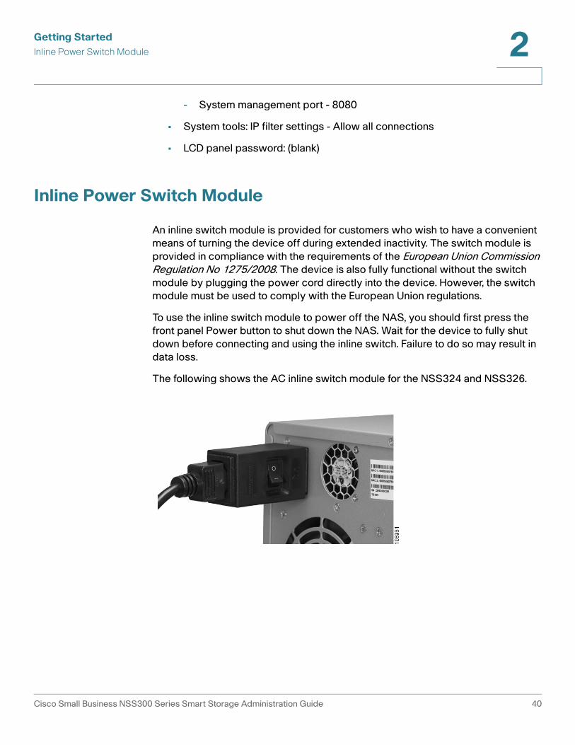
Inline Power Switch Module
An inline switch module is provided for customers who wish to have a convenient
means of turning the device off during extended inactivity. The switch module is
provided in compliance with the requirements of the European Union Commission Regulation No 1275/2008. The device is also fully functional without the switch
module by plugging the power cord directly into the device. However, the switch
module must be used to comply with the European Union regulations.
To use the inline switch module to power off the NAS, you should first press the
front panel Power button to shut down the NAS. Wait for the device to fully shut
down before connecting and using the inline switch. Failure to do so may result in
data loss.
The following shows the AC inline switch module for the NSS324 and NSS326.
Cisco Small Business NSS300 Series Smart Storage Administration Guide 40

Getting Started
Inline Power Switch Module 2
The following shows the DC inline switch module for the NSS322.
Cisco Small Business NSS300 Series Smart Storage Administration Guide 41

3
Managing the System
This chapter describes how to configure and manage your system Cisco Small
Business Smart Storage. The following sections are included:
• Status
• Administration
• Disk Management
• Network Shares
• Network Services
• Applications
• Backup
• External Device
Status
This section describes how to check the status of the system and includes the
following topics:
• System Information
• System Service
• Resource Monitor
• View Logs
Cisco Small Business NSS300 Series Smart Storage Administration Guide 42

Managing the System
Status 3
System Information
The Status > System Information window displays general information such as
system information, port status, and hardware information.
System Information
• Server Name—Name of the NAS.
• Firmware Version—Firmware version of the NAS.
• Firmware MD5 Checksum—MD5 checksum of the current firmware. This
number is useful to verify the integrity of the firmware.
• System Up Time—Time that the NAS has been in continuous operation in
days, hours, and minutes.
• Object ID—Object ID of the NAS, used in SNMP applications.
• PID VID—Product identifier (PID) and Version identifier (VID) of the NAS.
• Serial Number—Serial number of the NAS.
Cisco Small Business NSS300 Series Smart Storage Administration Guide 43

Managing the System
Status 3
Port Status
• Port No.—Number of the Ethernet port.
• Port Status—Status of the Ethernet port. Down indicates that the port is
not connected. Up indicates that the port is connected and operational.
• IP Address—IP address of the Ethernet port.
• MAC Address—MAC address of the Ethernet port.
• Packets Received—Number of packets received by the Ethernet port.
• Packets Sent—Number of packets sent by the Ethernet port.
• Error Packets—Number of packets detected with errors.
Hardware Information
• CPU Usage—Percentage of load on the CPU in the NAS.
• Total Memory—Total RAM memory in the NAS.
• Free Memory—Amount of free RAM memory in the NAS.
• CPU Temperature—Temperature of the CPU in the NAS.
• System Temperature—Internal system temperature of the NAS.
• HDD Temperature—Temperature of each hard drive in the NAS.
• System Fan Speed—RPM of each system cooling fan in the NAS.
System Service
The Status > System Service window displays the current system service
settings and status. Status shows a green color dot when the system service is
enabled.
Cisco Small Business NSS300 Series Smart Storage Administration Guide 44

Managing the System
Status 3
Microsoft Networking—This service is configured from the Network Services >
Microsoft Networking window.
• Enabled—Status of the Microsoft Networking file service.
• Server Type—Displays either Standalone Server or AD Domain Member
networking type.
• Workgroup—Workgroup to which the NAS belongs.
• Enable WINS Server—Status of WINS server.
• Enable Local Master Browser—Status of the Local Master Browser.
Apple Networking—This service is configured from the Network Services >
Apple Networking window.
• Enabled—Status of the Apple Networking protocol.
• Apple Zone Name—Name of the Apple zone.
Unix/Linux NFS—This service is configured from the Network Services >
NFS Service window.
• Enabled—Status of the Unix/Linux NFS service.
Web File Manager—This service is configured from the Applications >
Web File Manager window.
• Enabled—Status of the Web File Manager service.
Cisco Small Business NSS300 Series Smart Storage Administration Guide 45

Managing the System
Status 3
FTP Service—This service is configured from the Network Services >
FTP Service window.
• Enabled—Status of the FTP service.
• Port—Port number for FTP service.
• Maximum Connections—Maximum number of all FTP connections.
Multimedia Station—This service is configured from the Applications >
Multimedia Station window.
• Enable Multimedia Station—Status of the Multimedia Station service.
• Enable iTunes Service—Status of the iTunes service. This service is
configured from the Applications > iTunes Service window.
• Enable UPnP Media Server—Status of theUPnP Media Server service.
This service is configured from the Applications > UPnP Media Server
window.
Download Station—This service is configured from the Applications >
Download Station window.
• Enabled—Status of the Download Station service.
Web Server—This service is configured from the Network Services >
Web Server window.
• Enabled—Status of the Web Server service.
• Port—Port number for Web Server service.
DDNS Service—This service is configured from the Administration > Network >
DDNS window.
• Enabled—Status of the DDNS Service.
MySQL Server—This service is enabled, disabled, and configured from the
Applications > MySQL Server window.
• Enabled—Status of the MySQL Server service.
• Enable TCP/IP Networking—Status of TCP/IP Networking. This is enabled
from the Administration > Network window.
System Port Management—The System Port is configured from the
Administration > General Settings > System Administration window.
• Port—Value of the System Port.
Cisco Small Business NSS300 Series Smart Storage Administration Guide 46
Managing the System
Status 3
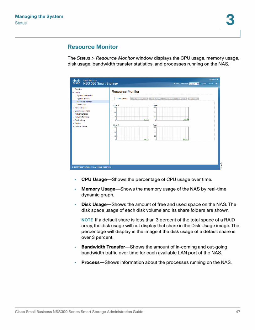
Resource Monitor
The Status > Resource Monitor window displays the CPU usage, memory usage,
disk usage, bandwidth transfer statistics, and processes running on the NAS.
• CPU Usage—Shows the percentage of CPU usage over time.
• Memory Usage—Shows the memory usage of the NAS by real-time
dynamic graph.
• Disk Usage—Shows the amount of free and used space on the NAS. The
disk space usage of each disk volume and its share folders are shown.
NOTE If a default share is less than 3 percent of the total space of a RAID
array, the disk usage will not display that share in the Disk Usage image. The
percentage will display in the image if the disk usage of a default share is
over 3 percent.
• Bandwidth Transfer—Shows the amount of in-coming and out-going
bandwidth traffic over time for each available LAN port of the NAS.
• Process—Shows information about the processes running on the NAS.
Cisco Small Business NSS300 Series Smart Storage Administration Guide 47

Managing the System
Status 3
View Logs
This section provides descriptions for the system logs and includes the following
sections:
• System Event Logs
• System Connection Logs
• On-Line Users
System Event Logs
The Status > View Logs > System Event Logs window displays the event logs,
including warning, error, and information messages. In the event of system
malfunction, you can retrieve the event logs to analyze system problems.
• Type—Type of log. Possible log types are Informational, Error, and Warning
messages.
• Date—Date that the log occurred.
• Time—Time that the log occurred.
• Users—User or system that generated the log entry.
• Source IP—IP address of the user.
• Computer Name—Name of the computer (if applicable) or local host that
generated the log entry.
• Content—Description of the log.
Cisco Small Business NSS300 Series Smart Storage Administration Guide 48

Managing the System
Status 3
System Connection Logs
The Status > View Logs > System Connection Logs window displays the HTTP,
FTP, Telnet, SSH, AFP, SAMBA, RADIUS, and iSCSI connection logs.
• Type—Type of log. Possible log types are Informational, Error, and Warning
messages.
• Date—Date that the log occurred.
• Time—Time that the log occurred.
• Users—User or system that generated the log entry.
• Source IP—IP address of the user.
• Computer Name—Name of the computer (if applicable) or local host that
generated the log entry.
• Connection Type—Type of connection. For example, HTTP, FTP, Telnet,
SSH, AFP, SAMBA, RADIUS, or iSCSI.
• Accessed Resources—Type of resource accessed. For example:
administrative activity, path, and name of files transferred.
• Action—Type of action. For example: login, log out, write, read, delete, and
rename.
Cisco Small Business NSS300 Series Smart Storage Administration Guide 49

Managing the System
Status 3
On-Line Users
The Status > View Logs > On-Line Users window displays the information for the
on-line users who are accessing the NAS. This displays real-time status versus
system log information, which shows a history.
• Type—Real-time status for on-line users.
• Login Date—Date that the user logged in.
• Login Time—Time that the user logged in.
• Users—Name of administrator or users account.
• Source IP—IP address of the user.
• Computer Name—Name of the computer (if applicable) or remote host IP
address that generated the log entry.
• Connection Type—Type of connection. For example, HTTP, FTP, Telnet,
SSH, AFP, SAMBA, RADIUS, or iSCSI.
• Accessed Resources—Type of resource accessed. For example,
administrative activity or network share folder.
Cisco Small Business NSS300 Series Smart Storage Administration Guide 50

Managing the System
Administration 3
Administration
From the Administration window, you can configure and view the following
parameters:
• General Settings
• Network
• Hardware
• Security
• Notification
• Power Management
• Network Recycle Bin
• Backup/Restore Settings
• System Logs Settings
• Firmware Upgrade
• Restore to Factory Default
• Network Service Discovery
• Users
• User Groups
General Settings
This section describes how to configure the general settings for the NAS.
• System Administration
• Date and Time
• Daylight Savings Time
• Language
• Password Strength
Cisco Small Business NSS300 Series Smart Storage Administration Guide 51

Managing the System
Administration 3
System Administration
From the Administration > General Settings > System Administration window,
you can configure the server name, port settings, and Secure Connection (SSL).
To configure the system administration settings:
STEP 1 Choose Administration > General Settings > System Administration from the
Navigation menu. The System Administration window opens.
STEP 2 Enter the parameters:
• Server Name—Name of the NAS. The server name can be up to 14
characters long and may contain alphabet characters, numbers, and hyphen
(-). The server does not accept names with spaces, periods (.), or names
composed of numbers only.
• System Port—Port for the system management. The default port is 8080.
The services which use this port include: System Management, Web File
Manager, Multimedia Station, and Download Station.
• Enable Secure Connection (SSL)—Click the check box to enable an SSL
secure connection.
- Port Number—Enter the port number for the SSL connection. The
default port is 443.
- Force secure connection (SSL) only—This option forces the use of an
SSL connection. After enabling the “Force secure connection (SSL) only”
option, the Web Administration can only be connected via HTTPS.
Cisco Small Business NSS300 Series Smart Storage Administration Guide 52

Managing the System
Administration 3
NOTE If the Web Server is enabled, the default port number is 80 for the
Web Server. To access the Web server and System Management, see
the following examples.
To access the Web Server:
http://<IP Address>
To access System Management:
http://<IP Address>:8080
STEP 3 Click Apply. The System Administration settings are updated to the NAS.
Date and Time
From the Administration > General Settings > Date and Time window you can set
the date, time, and time zone according to your location. You can also choose
whether or not to synchronze the NAS time with a Network Time Protocol (NTP)
server, or with the time of your computer.
If the settings are incorrect, the following problems may occur:
• When using a web browser to access the server or save a file, the display
time of the action will be incorrect.
• The time of event log displayed will be inconsistent with the actual time
when an action occurs.
Cisco Small Business NSS300 Series Smart Storage Administration Guide 53
Managing the System
Administration 3
To define the date and time:
STEP 1 Choose Administration > General Settings > Date and Time from the Navigation
menu. The Date and Time window opens.
STEP 2 From the Time Zone drop-down list, choose the time zone that the NAS is set to.
STEP 3 To set the Date and Time, click the down arrows by each value and select the
current date and time.
Enter the values for the following:
• Date Format—Select the order of how you want the day, month and year to
display. For example, DD/MM/yyyy or yyyy/MM/DD.
• Set the server time the same as your computer time—Click Update Now
to set the time of the NAS to the same time as your computer.
• Synchronize with an Internet time server automatically—To obtain time
automatically from an NTP server, click the check box. The first time you
enable the NTP server, it may take several minutes for time synchronization
before the time is correctly adjusted.
- Server—From the drop-down list, choose the NTP server name and click
Update Now.
- Click the Input Manually check box to enter an address that is different
from the drop-down list.
- Time Interval—Time interval for the date and time to be updated on the
NAS. Choose day(s) or hour(s) and a numeric time value.
STEP 4 Click Apply to update the Date and Time settings.
Daylight Savings Time
From the Administration > General Settings > Daylight Savings Time window you
can automatically update the time to accommodate daylight savings time on the
NAS.
Cisco Small Business NSS300 Series Smart Storage Administration Guide 54

Managing the System
Administration 3
To set the daylight savings time:
STEP 1 Choose Administration > General Settings > Daylight Savings Time from the
Navigation menu. The Daylight Savings Time window opens.
The following parameters are displayed:
• Time Zone—Current time zone that the NAS is set to. To change this value,
see Date and Time, page 53.
• Recent daylight saving time—Range of time set by the current Daylight
Saving Time settings.
• Offset—Current time offset by daylight savings time.
STEP 2 If needed, set the following parameters:
• Adjust system clock automatically for daylight saving time—Click the
check box to enable the NAS to automatically adjusts its time settings to
accommodate daylight savings time.
- Enable customized daylight saving time table—Click the check box to
create a custom Daylight Savings Time table. When selected, the
Customized Daylight Saving Time Tables opens. Click Add Daylight
Cisco Small Business NSS300 Series Smart Storage Administration Guide 55

Managing the System
Administration 3
Saving Time Data to create a new table. After a new table has been
created, select the option of the Daylight Savings Table that you would
like to use.
STEP 3 Click Apply to update the NAS with the daylight savings time settings.
Language
From the Administration > General Settings > Language window you can define
the language filename encoding. The NAS server uses Unicode as the default
filename encoding system and will work with operating systems (OS) that support
Unicode, such as Windows XP/Vista and MAC OS X.
If you are using an OS that does not support Unicode, such as Windows 95/98/ME,
select the same language as your OS for filename encoding. Since most FTP
software clients do not support Unicode, you will need to select the language that
your FTP client supports in order to properly display file and folder names on the
server. If the filename encoding is not properly selected, the following problems
may occur:
• You may be unable to create files or folders in certain languages.
• You may be unable to display filenames or folder names in certain
languages.
Cisco Small Business NSS300 Series Smart Storage Administration Guide 56

Managing the System
Administration 3
To define the language filename encoding:
STEP 1 Choose Administration > General Settings > Language from the Navigation
menu. The General Settings window opens.
STEP 2 From the Filename Encoding drop-down list, select the language you want to use
for filename encoding.
NOTE If you are using an OS that does not support Unicode, such as
Windows 95/98/ME, please select the same language as your OS for
filename encoding.
STEP 3 Click Apply. The language filename encoding is set and the NAS is updated.
Password Strength
From the Administration > General Settings > Password Strength window, you
can apply the password rules. You can enable one or more of the Password
Strength options to enforce password strength. After the setting has been applied,
the system will automatically check the validity of password set by users.
Cisco Small Business NSS300 Series Smart Storage Administration Guide 57

Managing the System
Administration 3
To define the password rules:
STEP 1 Choose Administration > General Settings > Password Strength from the
Navigation menu. The Password Strength window opens.
STEP 2 Enable one or more of the Password Strength options to enforce password
strength:
• The new password contains characters from at least three of the
following classes: lower case letters, upper case letters, digits, and
special characters—This option forces the user to use at least three of
these classes of characters: lower-case letters, upper-case letters, digits,
and special characters. Special characters are characters such as “!,” “@,”
and “#.”
• No character in the new password may be repeated more than three
times consecutively—This option specifies that no character in the new
password can be entered consecutively three times in a row such as
“123ZZZabc.”
• The new password must not be the same as the associated username, or
the username reversed—This option specifies that the password cannot
contain a variation of the username used to login to the NAS.
• The new password must not be "cisco", "ocsic", or any variant obtained
by changing the capitalization of letters therein, or by substituting “1” “|”
or “!” for i, and/or substituting “0” for “o”, and/or substituting “$” for
“s”—This option specifies that the password cannot contain a variation of
the word “Cisco.”
STEP 3 Click Apply. The password rules are applied to the NAS.
Network
This section describes how to configure the network settings, such as:
• TCP/IP
• DDNS
• IPv6
Cisco Small Business NSS300 Series Smart Storage Administration Guide 58

Managing the System
Administration 3
TCP/IP
From the Administration > Network > TCP/IP window, you can configure network
tranfer rates, default gateway, port trunking, DNS server, and Jumbo Frame Setting
(MTU).
To configure TCP/IP settings:
STEP 1 Choose Administration > Network > TCP/IP from the Navigation menu. The TCP/
IP window opens.
STEP 2 Configure or view the TCP/IP settings.
IP Address
• Interface—Physical NAS network interface.
• DHCP—Specifies whether this interface uses Dynamic Host Configuration
Protocol (DHCP).
• IP Address—IP address of this interface.
Cisco Small Business NSS300 Series Smart Storage Administration Guide 59

Managing the System
Administration 3
• Subnet Mask—Subnet mask of this interface.
• Gateway—IP address of the network gateway device.
• MAC Address—MAC address of this interface.
• Speed—Negotiated or specified link speed.
• MTU—Maximum Transmission Unit (MTU) for this interface.
• Link—Status of this interface. A green light indicates that the interface is
active. If only one NIC is used, the web interface will not show the other link
as down or not in use. It will only show both NICs if the NSS is configured as
a standalone from the discovery tool.
• Edit—Allows you to turn off DHCP, specify a static IP address, enable the
NAS to be a DHCP server, and allows you to specify link speed or set it to
auto negotiation. When you click Edit, the TCP/IP-Property window opens
and the following options are available:
• Network Speed—From the drop-down list, select from the following
options:
- Auto-negotiation—Allows the server to adjust transfer rates
automatically.
- 1000 Mbps full-duplex—Sets this transfer rate.
- 100 Mbps full-duplex—Sets this transfer rate.
• Obtain IP address settings automatically via DHCP—Select to enable the
NAS to acquire the IP address from a DHCP server.
• Use static IP address—Select to enable the NAS to use a static IP address.
Enter the static IP address, subnet mask, and default gateway.
• Enable DHCP Server—If DHCP is not available in the LAN where the NAS is
located, you can enable this function to enable the NAS as a DHCP server
and allocate dynamic IP address to DHCP clients in the LAN.
You can set the range of IP addresses allocated by the DHCP server and the
lease time. Lease time refers to the time that the IP address is leased to the
clients by the DHCP server. When the time expires, the client has to acquire
an IP address again.
Cisco Small Business NSS300 Series Smart Storage Administration Guide 60

Managing the System
Administration 3
For example, to establish a DLNA network and share the multimedia files on
the NAS to a DLNA digital media player via UPnP, without a NAT gateway that
supports DHCP server, you can enable DHCP server on the NAS. The NAS
will allocate dynamic IP addresses to media players or other clients
automatically and set up a local network.
NOTE If there is an existing DHCP server in your LAN, do not enable this
function. Otherwise, there will be IP address allocation conflicts and network
access errors.
Default Gateway
• Use the setting from—From the drop-down list, select the interface to use.
Port Trunking
All of the NAS models include Dual-LAN ports, which allow port trunking options
whereby two network interfaces function as one to increase bandwidth beyond
the limits of any single interface, while at the same time offering redundancy and
load balancing for higher availability. Following is a list of supported port trunking
modes.
NOTE Some trunking and redundancy options require a switch that also
supports these features. Note that incompatible mode settings may cause
the network interface to hang or affect overall network performance.
• Enable Network Port Trunking—Enable or disable port trunking. When
enabled, the following options are available from the drop-down list:
- Balance-rr (Round-Robin)—Round-Robin mode is good for general
purpose load balancing between the adapters. This mode transmits
packets in sequential order from the first available slave through the last.
Balance-rr provides load balancing and fault tolerance.
- Active Backup (Fail Over)—Active Backup uses just one adapter. It
switches to the second adapter if the first adapter fails. Only one slave in
the bond is active. The bond’s MAC address is only visible externally on
one port (network adapter) to avoid confusing the switch. Active Backup
mode provides fault tolerance.
- Balance XOR—Balance XOR balances traffic by splitting up outgoing
packets between the adapters, using the same one for each specific
destination when possible. It transmits based on the selected transmit
hash policy. The default policy is a simple slave count operating on Layer
2 where the source MAC address is coupled with destination MAC
Cisco Small Business NSS300 Series Smart Storage Administration Guide 61

Managing the System
Administration 3
address. Alternate transmit policies may be selected via the
xmit_hash_policy option. Balance XOR mode provides load balancing
and fault tolerance.
- Broadcast—Broadcast sends traffic on both interfaces. Broadcast mode
provides fault tolerance.
- IEEE 802.3ad (Dynamic Link Aggregation)—Dynamic Link Aggregation
uses a complex algorithm to aggregate adapters by speed and duplex
settings. It utilizes all slaves in the active aggregator according to the
802.3ad specification. Dynamic Link Aggregation mode provides load
balancing and fault tolerance but requires a switch that supports IEEE
802.3ad with LACP mode properly configured.
- Balance-tlb (Adaptive Transmit Load Balancing)—Balance-tlb uses
channel bonding that does not require any special switch support. The
outgoing traffic is distributed according to the current load on each slave
(computed relative to the speed). Incoming traffic is received by the
current slave. If the receiving slave fails, the other slave takes over the
MAC address of the failed receiving slave. Balance-tlb mode provides
load balancing and fault tolerance.
- Balance-alb (Adaptive Load Balancing)—Balance-alb is similar to
balance-tlb but also attempts to redistribute incoming (receive load
balancing) for IPV4 traffic. This setup does not require any special switch
support or configuration. The receive load balancing is achieved by ARP
negotiation sent by the local system on their way out and overwrites the
source hardware address with the unique hardware address of one of
the slaves in the bond such that different peers use different hardware
address for the server. Balance-alb mode provides load balancing and
fault tolerance.
NOTE If the NAS administration interface cannot be accessed due to an improperly
configured port trunking mode or incompatible switch, reset the network settings
by pressing the reset button on the back panel of the NAS for 3 seconds.
DNS Server
You can specify the DNS server address here, or choose to obtain it automatically.
If you have selected to obtain the IP address automatically, you do not need to
configure the primary and secondary DNS servers.
• Primary DNS Server—Enter the IP address of the Domain Name System
(DNS) server. This address is typically provided by your Internet Service
Provider (ISP).
• Secondary DNS Server—Enter a second DNS server.
Cisco Small Business NSS300 Series Smart Storage Administration Guide 62

Managing the System
Administration 3
Jumbo Frame Settings (MTU)
Jumbo Frames refer to Ethernet frames that are larger than 1500 bytes. Jumbo
Frames are designed to enhance Ethernet networking throughput and reduce the
CPU utilization of large file transfers by enabling more efficient, larger payloads
per packet. Maximum Transmission Unit (MTU) refers to the size (in bytes) of the
largest packet that a given layer of a communications protocol can transmit.
The NAS uses standard Ethernet frames, which are 1500 bytes by default. If your
network appliances support Jumbo Frame setting, select the appropriate MTU
value for your network environment. The NAS supports 4074, 7418, and 9000
bytes for MTU.
NOTE Jumbo Frame setting is valid in a Gigabit network environment only.
Also, all network appliances connected must enable Jumbo Frame and use
the same MTU value.
• Select Jumbo Frame Setting—From the drop-down list, select the MTU
value for your network. The NAS supports 4074, 7418, and 9000 bytes for
MTU.
STEP 3 Click Apply to save the settings.
NOTE If the NAS administration interface cannot be accessed due to an improperly
configured Jumbo Frame setting or incompatible switch, reset the network
settings by pressing the reset button on the back panel of the NAS for 3 seconds.
DDNS
From the Administration > Network > DDNS window, you can configure Dynamic
DNS Service (DDNS). DDNS allows Internet access to the server using a domain
name rather than an IP address. DDNS also maintains IP address information even
when the client received a dynamic IP assignment subject to frequent change by
the ISP. This configuration ensures that the server is always available independent
of the IP address. To use this service you must establish an account with a
dynamic DNS service provider.
Cisco Small Business NSS300 Series Smart Storage Administration Guide 63

Managing the System
Administration 3
To configure DDNS settings:
STEP 1 Choose Administration > Network > DDNS from the Navigation menu. The DDNS
window opens.
STEP 2 Configure the DDNS settings.
DDNS Service
• Enable Dynamic DNS Service—Click this option to enable a DDNS service.
DDNS is useful when you are hosting your own website, FTP server, or other
server behind the NAS. If DDNS is enabled, you can select a fixed host and
domain name to a dynamic Internet IP address. Before you can use this
feature, you need to sign up for a DDNS service.
• Select DDNS Server— From the drop-down list, select a DDNS server. The
NAS supports the following DDNS server providers:
- www.tzo.com
- www.dyndns.org
- update.ods.org
- members.dhs.org
- www.dyns.cx
- www.3322.org
- www.no-ip.com
Cisco Small Business NSS300 Series Smart Storage Administration Guide 64

Managing the System
Administration 3
• Enter the account information you registered with the DDNS provider—
Complete the following fields.
- User Name—Username that you registered with the DDNS provider.
- Password—Password registered with the DDNS provider.
- Host Name—Host name registered with the DDNS provider.
• Check the External IP Address Automatically—Enable this option if your
NAS is located behind a gateway. The NAS checks the external (WAN) IP
automatically at the specified interval. If the IP address is changed, the NAS
will inform the DDNS provider automatically to ensure it can be accessed via
the host name. From the drop-down list, select the specified interval.
• Update DDNS using the alternate port 21333 (bypass local web proxy)—
Click to enable updating DDNS using the alternate port 21333.
Recent DDNS Update Result
• Connection IP Last Checked—WAN IP address last checked.
• Next Check for Connection IP—Time schedule that WAN IP address will
next be checked. Can also show as a blank field.
• Last DDNS Update Time—Time that the DDNS was last updated.
• Update Server Response—OK or Failed response.
STEP 3 Click Apply to save the DDNS Service settings.
IPv6
From the Administration > Network > IPv6 window, you can configure IPv6. The
system NAS supports IPv6 connectivity with stateless address configurations.
Router Advertisement Daemon (RADVD) is also available for sending out router
advertisements described in RFC 2461 for IPv6. Hosts within the same network
can automatically configure their addresses. This option should be used when the
network router is configured as dual stack (IPv4 and IPv6). The router will send the
advertisement. Newer clients such as Windows 7, Vista, MAC OS 10.5 (and
greater) will benefit from IPv6, as they will query DNS via IPv6 first and then IPv4.
The latest browsers such as IE8, Safari 4, and Firefox prefer IPv6 DNS but will fall
back to IPv4 if IPv6 fails. This setting also needs to be applied on the router.
Cisco Small Business NSS300 Series Smart Storage Administration Guide 65

Managing the System
Administration 3
The services on the NAS that support IPv6 include:
• Remote replication
• Web Server
• FTP
• iSCSI (Virtual disk drives)
• SSH
To configure IPv6:
STEP 1 Choose Administration > Network > IPv6 from the Navigation menu. The IPv6
window opens.
STEP 2 Click the Enable IPv6 check box to use this function. The NAS will restart
automatically. After the system restarts the settings for the IPv6 interface will
display in the IPv6 window.
• Edit—Allows you to edit the IPv6 settings. When you click Edit, the IPv6-
Property window opens and the following options are available:
- IPv6 Auto Configuration—If you have an IPv6 enabled router on the
network, click this option to allow the NAS to acquire the IPv6 address
and the configurations automatically.
- Use static IP address—Click to use a static IP address. Enter the IP
address (for example, 2001:bc95:1234:5678), prefix length (for example,
64), and the gateway address for the NAS. Contact your ISP for the prefix
and the prefix length information.
Cisco Small Business NSS300 Series Smart Storage Administration Guide 66

Managing the System
Administration 3
- Enable Router Advertisement Daemon (radvd)—Click to enable this
option and configure the NAS as an IPv6 host that distributes IPv6
addresses to the local clients which support IPv6. Enter the prefix and
prefix length.
STEP 3 Enter the name of the primary DNS server in the first field and the name of the
secondary DNS server in the second field. Contact your ISP or network
administrator for the DNS server information.
NOTE If you selected IPv6 auto configuration in the previous steps, leave the
double colons (::) in both fields.
STEP 4 Click Apply to save the IPv6 settings.
Hardware
From the Administration > Hardware window, you can configure the hardware
related functions of the NAS.
Cisco Small Business NSS300 Series Smart Storage Administration Guide 67

Managing the System
Administration 3
To configure the hardware related functions:
STEP 1 Choose Administration > Hardware from the Navigation menu. The Hardware
window opens.
STEP 2 Configure the following settings.
Hardware
• Enable configuration reset switch—Enables the reset switch at the back
panel of the NAS. You can press the reset button for 3 or 10 seconds to reset
the administrator password and system settings to default. If disabled, the
reset switch cannot be used to set the unit to its default settings. For more
information about the reset, see Hardware System Reset, page 242.
• Enable hard disk standby mode—Enables disk standby mode if inactive for
more than the specified time.
• Enable light signal alert when the free size of SATA disk is less than the
value—The Status LED indicator flashes red and green when this function is
enabled and the free space of the SATA disk is less than the value. The
recommended range for this value is 1-51200 MB.
• Enable write cache (for EXT4)—Enable to allow the system to use internal
cache when the filesystem is configured for EXT4.
Buzzer Control
Enable alarm buzzer
• System operations (startup, shutdown, and firmware upgrade)—Enable
to allow an audible beep when a system operation occurs.
• System events (error and warning)—Enable to allow an audible beep
when an error or warning occurs.
Smart Fan Configuration
• When ALL of the following temperature readings are met the fan will
rotate at low speed—Click to use the default smart fan settings. When the
system default settings are selected, the fan rotation speed is automatically
adjusted when the server temperature, CPU temperature, and hard drive
temperature meet the criteria.
• Self-defined temperature—Click to define the settings manually. Select the
temperature from the drop-down lists.
Cisco Small Business NSS300 Series Smart Storage Administration Guide 68

Managing the System
Administration 3
STEP 3 Click Apply to save the hardware settings.
Security
This section describes how to configure the security on the NAS and includes the
following:
• Security Level
• Network Access Protection
• SSL Certificate and Private Key
Security Level
From the Administration > Security > Security Level window, you can configure
the security level for the NAS as high, medium, or low.
To configure the security level:
STEP 1 Choose Administration > Security > Security Level from the Navigation menu.
The Security Level window opens.
STEP 2 Select the security level for the NAS.
• High—Only allow connections that are on the list. This is commonly referred
to as a white list. To add connections to the list, click the green “+” icon and
add the connection. Click the red “-” icon to remove a connection.
Cisco Small Business NSS300 Series Smart Storage Administration Guide 69

Managing the System
Administration 3
- Single IP Address—Enter the IP address from which the connections to
this NAS are allowed.
- Specify IP addresses of certain network by setting IP address and
netmask—Enter the IP address and netmask of the network from which
the connections to this NAS are allowed.
- IP Range—Enter the IP address range from which the connections to this
NAS are allowed.
• Medium—Deny connections that are on the list. This is commonly referred
to as a black list. When the connection of a host server is denied, all protocols
of that server are not allowed to access the NAS. To add connections to the
list, click the green “+” icon and add the connection. Click the red “-” icon to
remove a connection.
- Single IP Address—Enter the IP address from which the connections to
this NAS are denied.
- Specify IP addresses of certain network by setting IP address and
netmask—Enter the IP address and netmask of the network from which
the connections to this NAS are rejected.
- IP Range—Enter the IP address range from which the connections to this
NAS are rejected.
• Low—Allow all connections regardless of connections in the list.
STEP 3 Click Apply to save the security settings. The network services will be restarted
and current connections to the server will be disconnected.
Network Access Protection
From the Administration > Security > Network Access Protection window, you
can enhance the security of the system and prevent unwanted intrusion. Network
access protection shields the NAS from Internet attacks by automatic IP blocking.
You can define the rules of IP blocking for different services or protocols.
NOTE If the Security Level is set as High, Network Access Protection will be
disabled since only connections from specified IP addresses are permitted
access.
Cisco Small Business NSS300 Series Smart Storage Administration Guide 70

Managing the System
Administration 3
STEP 1 Choose Administration > Security > Network Access Protection from the
Navigation menu. The Network Access Protection window opens.
STEP 2 Click Enable network access protection to enable network access protection.
STEP 3 Select the different services or protocols and from the drop-down lists, select the
time intervals to define the rules. For example:
In 10 minutes, after unsucessful attempts for 10 times, block the IP for 5 minutes.
You can select the following services or protocols:
• SSH
• Telnet
• HTTP(S)
• FTP
• SAMBA
• AFP
STEP 4 Click Apply to save the settings.
Cisco Small Business NSS300 Series Smart Storage Administration Guide 71
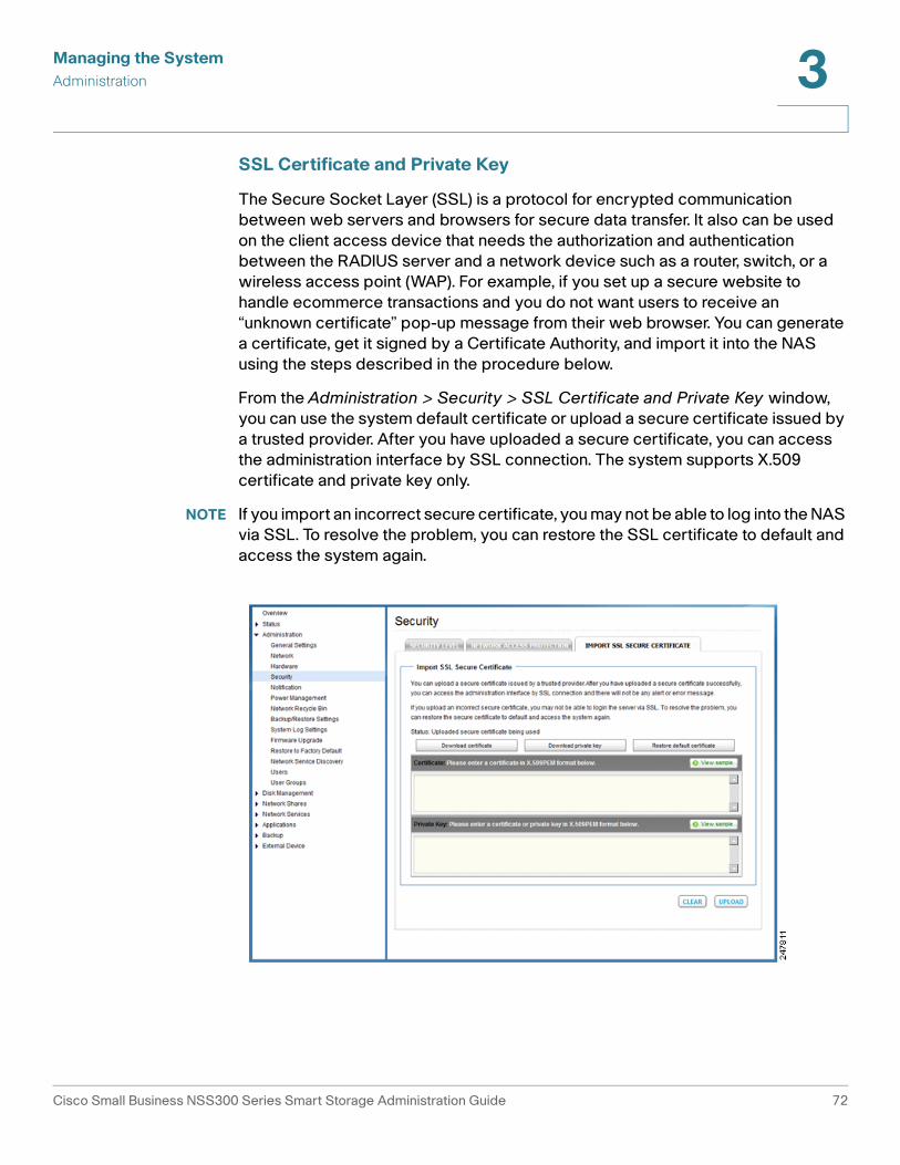
Managing the System
Administration 3
SSL Certificate and Private Key
The Secure Socket Layer (SSL) is a protocol for encrypted communication
between web servers and browsers for secure data transfer. It also can be used
on the client access device that needs the authorization and authentication
between the RADIUS server and a network device such as a router, switch, or a
wireless access point (WAP). For example, if you set up a secure website to
handle ecommerce transactions and you do not want users to receive an
“unknown certificate” pop-up message from their web browser. You can generate
a certificate, get it signed by a Certificate Authority, and import it into the NAS
using the steps described in the procedure below.
From the Administration > Security > SSL Certificate and Private Key window,
you can use the system default certificate or upload a secure certificate issued by
a trusted provider. After you have uploaded a secure certificate, you can access
the administration interface by SSL connection. The system supports X.509
certificate and private key only.
NOTE If you import an incorrect secure certificate, you may not be able to log into the NAS
via SSL. To resolve the problem, you can restore the SSL certificate to default and
access the system again.
Cisco Small Business NSS300 Series Smart Storage Administration Guide 72

Managing the System
Administration 3
To import an SSL secure certificate:
STEP 1 Choose Administration > Security > SSL Certificate and Private Key from the
Navigation menu. The SSL Certificate and Private Key window opens.
STEP 2 Click View sample to view a sample certificate or private key.
STEP 3 Enter the certificate and private key information in the applicable fields.
STEP 4 Click Upload to upload the certificate and private key or click Clear to remove any
information from the certificate and private key fields.
Another example of a client device accessing the network using the RADIUS
server for authorization and authentication is if your network is set up with secure
access that requires you to use a certificate and/or private key that is imported
into the client device such as a laptop, mobile device, or surveillance cameras.
Your client device requires the support of 802.1x with Extensive Authentication
Protocol (EAP) available for configuring the certificate and private key. The
following steps illustrate the use of this RADIUS feature.
Cisco Small Business NSS300 Series Smart Storage Administration Guide 73

Managing the System
Administration 3
To export an SSL secure certificate and private key:
STEP 1 Choose Administration > Security > SSL Certificate and Private Key from the
Navigation menu. The Import and Export SSL Secure Certificate window opens.
STEP 2 Click Download certificate to download the file. The window popup asks you to
save to a local drive on your PC. The file is saved by default as “SSLcertificate.crt.”
You need to save this file with a “.pem” extension or to an extension that your client
access supports.
STEP 3 Click Download private key to download the file. The window popup asks you to
save to a local drive on your PC. The file is saved by default as
“SSLprivatekey.key.” You need to save this file with a “.pem” extension or to an
extension that your client access supports.
Notification
This section describes configuring the NAS system notifications settings, such as:
• Configure SMTP Server
• Configure SMSC Server
• Alert Notification
Configure SMTP Server
From the Administration > Notification > Configure SMTP Server window, you
can configure the Simple Mail Transfer Protocol (SMTP) server. The NAS supports
email alert to inform you about any system warnings or errors. To receive the alert
by email, you need configure the SMTP server.
Cisco Small Business NSS300 Series Smart Storage Administration Guide 74
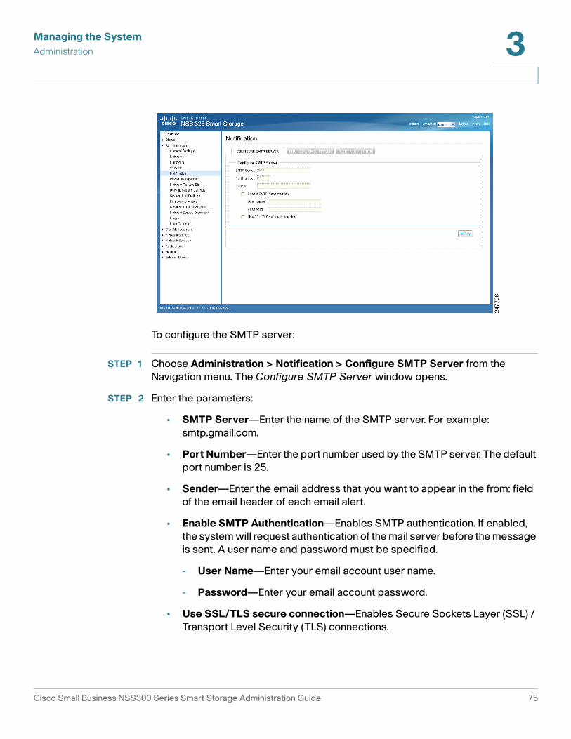
Managing the System
Administration 3
To configure the SMTP server:
STEP 1 Choose Administration > Notification > Configure SMTP Server from the
Navigation menu. The Configure SMTP Server window opens.
STEP 2 Enter the parameters:
• SMTP Server—Enter the name of the SMTP server. For example:
smtp.gmail.com.
• Port Number—Enter the port number used by the SMTP server. The default
port number is 25.
• Sender—Enter the email address that you want to appear in the from: field
of the email header of each email alert.
• Enable SMTP Authentication—Enables SMTP authentication. If enabled,
the system will request authentication of the mail server before the message
is sent. A user name and password must be specified.
- User Name—Enter your email account user name.
- Password—Enter your email account password.
• Use SSL/TLS secure connection—Enables Secure Sockets Layer (SSL) /
Transport Level Security (TLS) connections.
Cisco Small Business NSS300 Series Smart Storage Administration Guide 75

Managing the System
Administration 3
STEP 3 Click Apply to save the settings.
Configure SMSC Server
From the Administration > Notification > Configure SMSC Server window, you
can configure the Short Message Service Center (SMSC) settings to send instant
system alerts via the SMS service provided by the SMS provider. The default SMS
service provider is Clickatell. You can also add your own SMS service provider.
To configure the SMSC server:
STEP 1 Choose Administration > Notification > Configure SMSC Server from the
Navigation menu. The Configure SMSC Server window opens.
STEP 2 From the SMS Service Provider drop-down list, select one of the following:
• Clickatell—This is the default SMS service provider.
• Add SMS service provider—Select to add your SMS service provider.
Different parameter settings are displayed dependent on your choice of the
default service provider or adding your SMS service provider.
STEP 3 Enter the parameters for either Clickatell or Add SMS service provider:
Cisco Small Business NSS300 Series Smart Storage Administration Guide 76

Managing the System
Administration 3
Clickatell
• Enable SSL Connection—Click to enable the SSL connection.
• SSL Port—Enter the port number used for the SSL connection. The default
port is 443.
• SMS Server Login Name—Enter the SMS server login name.
• SMS Server Login Password—Enter the SMS server login password.
• SMS Server API_ID—Enter the SMS server API ID provided from your
provider. In order to get the API_ID, the user needs to add the NAS product
name to the service provider list. In this case, it will be Cisco. This ID is
different from the Client ID that the user receives when product is registered.
Add SMS service provider
• SMS Service Provider—Enter the name of the SMS service provider.
• URL Template Text—Enter the text as specified in the URL Template
Replaceable Parameters table.
NOTE You will not be able to receive the SMS properly if the URL template
text entered does not follow your SMS service provider’s format.
STEP 4 Click Apply to save the SMSC server settings.
Alert Notification
From the Administration > Notification > Alert Notification window, you can
configure settings to receive instant SMS messages or email alerts in the event
that a system warning or error occurs.
Cisco Small Business NSS300 Series Smart Storage Administration Guide 77

Managing the System
Administration 3
To configure the alert notification:
STEP 1 Choose Administration > Notification > Alert Notification from the Navigation
menu. The Alert Notification window opens.
STEP 2 Enter the parameters:
Alert Notification
• Send system error alert by—From the drop-down list, select how you want
the system error alert sent. The options are:
- No alert—Select if you do not want system error alerts sent.
- Email—Select to receive system error alerts via email.
- SMS—Select to receive system error alerts via SMS.
- Email & SMS—Select to receive system error alerts via email and SMS.
• Send system warning alert by—From the drop-down list, select how you
want the system warning alert sent. The options are:
- No alert—Select if you do not want system warning alerts sent.
- Email—Select to receive system warning alerts via email.
Cisco Small Business NSS300 Series Smart Storage Administration Guide 78
Managing the System
Administration 3
E-mail Notification Settings
• E-mail address 1—Enter the email address to receive the alert notification.
• E-mail address 2—Enter a second email address to receive the alert
notification.
• Send A Test E-mail—Click to send a test email to the email address
specified the email notification settings.
NOTE The SMTP server must be configured for alert mail delivery.
SMS Notification Settings
• Country Code—From the drop-down list, select the country code where
the cell phone number is located.
• Cell Phone No. 1—Enter the cell phone number to receive the SMS
notification.
• Cell Phone No. 2—Enter a second cell phone number to receive the SMS
notification.
• Send A Test SMS message—Click to send a test SMS message to the cell
phone numbers specified in the SMS notification settings.
NOTE The SMSC server must be configured to send SMS notification.
STEP 3 Click Apply to save the alert notification settings.
Power Management
From the Administration > Power Management window, you can restart or shut
down the NAS immediately, define the behavior of the NAS when the power
resumes after a power outage, and set a schedule for automatic system power on
and off.
Cisco Small Business NSS300 Series Smart Storage Administration Guide 79

Managing the System
Administration 3
To configure power management:
STEP 1 Choose Administration > Power Management from the Navigation menu. The
Power Management window opens.
STEP 2 Set the parameters:
• Restart/ Shutdown—To restart the NAS immediately, click RESTART. To
shutdown the NAS immediately, click SHUTDOWN.
• Configure Wake on LAN—Enable this option to power on the NAS remotely
by Wake on LAN. If enabled, this feature allows the NAS to be powered on
remotely from the LAN by the NSS Discovery Tool included on the Setup
Wizard CD.
NOTE If the power connection is physically removed when the NAS is turned
off, Wake on LAN will not function whether or not the power supply is
reconnected afterwards.
- Enable—Click to enable Wake on LAN.
- Disable—Click to disable Wake on LAN.
• When the AC power resumes—Specify the action the NAS should take
when the power resumes after power loss.
- Resume the server to the previous power-on or power-off status—
The NAS will return to its previous power-on or power-off status.
Cisco Small Business NSS300 Series Smart Storage Administration Guide 80
Managing the System
Administration 3
- Turn on the server automatically—The NAS will power on as soon as
power is restored.
- The server should remain off—The NAS will remain off when power
returns.
• Set power on/power off/restart schedule—This option allows you to
power on or power off the NAS on a schedule. From the drop-down lists,
select everyday, weekdays, weekend, or any days of the week and set the
time for automatic system power on, power off, or restart. Weekdays
represent Monday to Friday. Weekend represents Saturday and Sunday. Up
to 15 schedules can be set. Click “+” to add a new schedule and click “-” to
delete a schedule.
- Enable schedule—Click to enable the schedule.
- Postpone the restart/shutdown schedule when replication job is on
progress—Enable to allow the scheduled system restart or shutdown to
be carried out after a running replication job completes. Otherwise, the
system will ignore the running replication job and execute scheduled
system restart or shutdown.
STEP 3 Click Apply to save the power management settings.
Network Recycle Bin
From the Administration > Network Recycle Bin window, you can enable a
network recycle bin or empty the network recycle bin. When enabled, there is a
corresponding network recycle bin for each disk/disk volume.
The network recycle bin number is assigned accordingly to the creation of the
disk volume number. The first array volume created will be assigned to Network
Recycle Bin #1 and second array volume created will be assigned to Network
Recycle Bin #2 and so on. For example: The first RAID 5 volume creation will
automatically be assigned Network Recycle Bin #1. Then if a user added a new
single disk from Disk Management > Volume Management, a new Network
Recycle Bin #2 will be assigned.
Refer to the Property of the network share in Network Shares > Share Folders to
view the details for each network recycle bin.
After enabling Network Recycle Bin, all of the files deleted via Samba/CIFS
(not NFS, AFP, FTP) in the network folders of the NAS are moved to the Network
Recycle Bin network folder.
Cisco Small Business NSS300 Series Smart Storage Administration Guide 81

Managing the System
Administration 3
To enable the network recycle bin:
STEP 1 Choose Administration > Network Recycle Bin from the Navigation menu. The
Network Recycle Bin window opens.
STEP 2 Click Enable Network Recycle Bin to enable the network recycle bin. The system
will keep all files deleted from any of the network share folders in the Network
Recycle Bin. The files will be kept accordingly with the Network Recycle Bin
number respective to the order of the disk volume when it was created.
• Empty Network Recycle Bin—To the clear network recycle bin, click
EMPTY NETWORK RECYCLE BIN.
!CAUTION All files in the network recycle bins are permanently deleted when clicking Empty
Network Recycle Bin.
STEP 3 Click Apply to save the settings.
Cisco Small Business NSS300 Series Smart Storage Administration Guide 82

Managing the System
Administration 3
Backup/Restore Settings
From the Administration > Backup/Restore Settings window, you can backup and
restore system settings.
NOTE It is good practice to periodically back up the system settings, especially if
changes are made to the NAS configuration and saved to your computer. Since the
NAS backup config files are always named the same (backupdata.bin), you can
save the backup config files either in uniquely-named folders (for example,
backup041310) or rename the config file (for example, default name is
backupdata.bin; rename to backup041310.bin).
To configure the system backup and restore settings:
STEP 1 Choose Administration > Backup/Restore Settings from the Navigation menu.
The Backup/Restore Settings window opens.
STEP 2 Enter the parameters:
Backup System Settings
• Backup—Click to backup all of the system settings, including the NAS user
accounts, server name, system application settings, network services
settings, and network configuration.
Restore System Settings
• Restore—Click Restore to restore all of the settings.
Cisco Small Business NSS300 Series Smart Storage Administration Guide 83

Managing the System
Administration 3
- Browse—Click to select a previously saved setting file and click Restore.
NOTE It is important for the user to backup the system settings on a weekly basis so that
the most current system changes are included in the backup.
TFTP Configuration—TFTP configuration is used to enable a saved configuration
to be pushed out to the NAS. For instance, a reseller might create a custom
configuration to distribute to all of their clients. The custom configuration is pushed
out to the NAS as soon as the NAS boots up and makes a DHCP request, such as
getting an IP address from the router.
• Enable Automatic Configuration Download from TFTP Server
(Option 66/150 & 67)—When enabled, the NAS will automatically retrieve
the system configuration from a Trivial File Transfer Protocol (TFTP) server
which is provided by the DHCP server when the NAS boots up.
- Backup TFTP Server—Enter the name of the backup TFTP server. If the
TFTP server provided by the DHCP server cannot be accessed, the NAS
will acquire the backup configuration file from the backup TFTP server.
- Backup Configuration File—Enter the name of the backup configuration
file from the backup TFTP server you entered in Backup TFTP Server.
NOTE If the NAS is configured with a static IP address, the system will not
acquire the TFTP configuration from the DHCP server and will use the NAS
internal configuration file for system startup, even if Enable Automatic
Configuration Download from TFTP Server is enabled.
STEP 3 Click Apply to save the settings.
System Logs Settings
This section describes the system logs and includes the following sections:
• System Log Settings
• System Event Logs
• System Connection Logs
• On-Line Users
• Syslog
Cisco Small Business NSS300 Series Smart Storage Administration Guide 84

Managing the System
Administration 3
System Log Settings
From the Administration > System Log Settings window, you can view, save, and
clear the system event logs.
System Event Logs
From the Administration > System Log Settings > System Event Logs window,
you can display warning, error, and informational messages. In the event of a
system malfunction or an error indicator light on the front panel, the event logs can
be retrieved to help diagnose the system problem.
To view the system event logs:
STEP 1 Choose Administration > System Log Settings > System Event Logs from the
Navigation menu. The System Event Logs window opens and displays the
following information.
• Type—Type of log. Log types are Informational, Error, and Warning
messages.
• Date—Date that the log occurred.
• Time—Time that the log occurred.
• Users—User or system that generated the log entry.
• Source IP— IP address of the user.
• Computer Name—Name of the computer (if applicable) or local host that
generated the log entry.
Cisco Small Business NSS300 Series Smart Storage Administration Guide 85

Managing the System
Administration 3
• Content—Description of the log.
STEP 2 From the drop-down list, you can filter the type of log message displayed. Log
types are All events, Informational, Error, and Warning messages.
STEP 3 From the drop-down list, Displays records per page, select the number of
records to display.
STEP 4 Click the arrows in the lower right to navigate forward or back on the System Event
Logs window.
To clear a system event log:
STEP 1 Choose Administration > System Log Settings > System Event Logs from the
Navigation menu. The System Event Logs window opens.
STEP 2 Right-click a single log and delete the record. Or click Clear to delete all of the
system event logs.
To save the system event logs:
STEP 1 Choose Administration > System Log Settings > System Event Logs from the
Navigation menu. The System Event Logs window opens and displays the
following information.
STEP 2 Click Save and save the .csv file generated by the system.
System Connection Logs
From the Administration > System Log Settings > System Connection Logs
window, you can filter the type of message you want to view, specify connection
types to be logged, start or stop logging events, and clear or save the system
connection logs. From the System Connection Logs window, you can also
disconnect the IP address connection or add the IP address to the black list.
Cisco Small Business NSS300 Series Smart Storage Administration Guide 86

Managing the System
Administration 3
To view the system connection logs:
STEP 1 Choose Administration > System Log Settings > System Connection Logs from
the Navigation menu. The System Connection Logs window opens and displays
the following information.
• Type—Type of log. Log types are Informational, Error, and Warning
messages.
• Date—Date that the log occurred.
• Time—Time that the log occurred.
• Users—User or system that generated the log entry.
• Source IP—IP address of the user.
• Computer Name—Name of the computer (if applicable) or local host that
generated the log entry.
• Connection Type—Type of connection. For example, HTTP, FTP, Telnet,
SSH, AFP, SAMBA, RADIUS, or iSCSI.
• Accessed Resources—Type of resource accessed. For example,
administrative activity, folder path, and name of files that have been
accessed.
• Action—Type of action. Examples of action types are login, log out, write,
delete, read, or rename.
STEP 2 From the drop-down list, you can filter the type of log message displayed. Log
types are All events, Informational, Error, and Warning messages.
Cisco Small Business NSS300 Series Smart Storage Administration Guide 87

Managing the System
Administration 3
STEP 3 From the drop-down list, Displays records per page, select the number of
records to display.
STEP 4 Click the arrows in the lower right to navigate forward or back on the System
Connection Logs window.
To configure the system connection logs options:
STEP 1 Choose Administration > System Log Settings > System Connection Logs from
the Navigation menu. The System Connection Logs window opens.
STEP 2 Click Options to specify the connection type to be logged. The Connection Type
window opens.
Set the following parameters:
• Select the connection type to be logged—The system supports logging
the HTTP, FTP, Telnet, SSH, AFP, SAMBA, RADIUS, and iSCSI connections.
• When the number of logs reaches 10,000, archive the connection logs
and save the file in the folder—Click to automatically save the log files in
one of the created network share folders when the logs reach 10,000 events.
- From the drop-down list, select the network share folder location to save
the logs.
STEP 3 Click Apply to save the system connection logs options.
STEP 4 Click Start Logging to enable the system connection logs feature. To disable this
feature, click Stop Logging.
To clear a system connection log:
STEP 1 Choose Administration > System Log Settings > System Connection Logs from
the Navigation menu. The System Connection Logs window opens.
STEP 2 Right-click a single log and delete the record. Or click Clear to delete all of the
system connection logs.
Cisco Small Business NSS300 Series Smart Storage Administration Guide 88

Managing the System
Administration 3
To save the system connection logs:
STEP 1 Choose Administration > System Log Settings > System Connection Logs from
the Navigation menu. The System Connection Logs window opens and displays
the following information.
STEP 2 Click Save and save the .csv file generated by the system.
To disconnect the IP address connection or add the IP address to the block list:
STEP 1 Choose Administration > System Log Settings > System Connection Logs from
the Navigation menu. The System Connection Logs window opens.
STEP 2 Right-click a log and select from the following options:
• Disconnect this connection—Select to disconnect the selected IP address.
• Add to the block list—Select to block the selected IP address.
- From the drop-down list, select the time frame that you want the IP
address to be blocked.
• Disconnect this connection and block the IP—Select to disconnect the
connection and also block the IP address.
STEP 3 Click OK to save the settings or click Cancel to exit.
On-Line Users
From the Administration > System Log Settings > On-Line Users window, you
can view information about the users accessing the system. This displays real-
time status versus system log information.
Cisco Small Business NSS300 Series Smart Storage Administration Guide 89

Managing the System
Administration 3
• Type—Real-time status for on-line users.
• Login Date—Date that the user logged in.
• Login Time—Time that the user logged in.
• Users—User or system that generated the log entry.
• Source IP—IP address of the user.
• Computer Name—Name of the computer (if applicable) or local host that
generated the log entry.
• Connection Type—Type of connection. For example, HTTP, FTP, Telnet,
SSH, AFP, SAMBA, RADIUS, or iSCSI.
• Accessed Resources—Type of resource accessed. For example,
administrative activity or network share folder.
From the Administration > System Log Settings > On-Line Users window, you
can disconnect the IP address connection or add the IP address to the block list.
To disconnect the IP address connection or add the IP address to the block list:
STEP 1 Choose Administration > System Log Settings > On-Line Users from the
Navigation menu. The On-Line Users window opens.
STEP 2 Right-click a log and select from the following options:
• Disconnect this connection—Select to disconnect the selected IP address.
Cisco Small Business NSS300 Series Smart Storage Administration Guide 90

Managing the System
Administration 3
• Add to the block list—Select to block the selected IP address.
- From the drop-down list, select the time frame that you want the IP
address to be blocked.
• Disconnect this connection and block the IP—Select to disconnect the
connection and also block the IP address.
STEP 3 Click OK to save the settings or click Cancel to exit.
Syslog
From the Administration > System Log Settings > Syslog window, you can enable
syslog to save the event logs and connection logs to a remote syslog server.
Syslog is a standard for forwarding log messages in an IP network. The NAS has a
built-in syslog server. For more information, see Syslog Server, page 194.
To configure the syslog settings:
STEP 1 Choose Administration > System Log Settings > Syslog from the Navigation
menu. The Syslog window opens.
STEP 2 Click Enable syslog.
STEP 3 Enter the hostname or IP address of the syslog server in the Syslog Server IP field.
Cisco Small Business NSS300 Series Smart Storage Administration Guide 91

Managing the System
Administration 3
STEP 4 In the UDP Port field, enter the UDP port number used to transmit syslog
messages. Default is 514.
STEP 5 Select the logs to record.
• System Event Logs—Enable to record the system event logs.
• System Connection Logs—Enable to record the system connection logs.
You must enable and configure the syslog server from Applications > Syslog
Server in order to use this feature.
STEP 6 Click Apply to save the syslog settings.
Firmware Upgrade
From the Administration > Firmware Upgrade window, you can view the current
firmware version and update the firmware on the NAS. The current NAS settings
will not change while performing the firmware version update.
!CAUTION As a precautionary measure, backup the NAS system configuration before
upgrading the firmware.
Cisco Small Business NSS300 Series Smart Storage Administration Guide 92

Managing the System
Administration 3
To upgrade the firmware:
STEP 1 Choose Administration > Firmware Upgrade from the Navigation menu. The
Firmware Upgrade window opens. The current firmware version is displayed.
STEP 2 Click Browse to locate the correct firmware file for the system update. Before
updating the system, verify that the product model and firmware version you are
going to update is correct.
!CAUTION As a precautionary measure, backup the NAS system configuration before
upgrading the firmware.
STEP 3 Click Update The System.
Within 15 seconds, a MD5 checksum result window will display to confirm the
integrity of the system. After the successful integrity check of the NAS, click OK
for the new firmware file to upload to the NAS. After this has completed, a
message displays and asks you to reboot the system. Please wait patiently. A
system log in window will automatically display after the successful update to the
new firmware.
Restore to Factory Default
From the Administration > Restore to Factory Default window, you can restore all
NAS settings to the factory default settings.
!CAUTION When you restore to the factory default settings, all of the drive data, user
accounts, network shares, and system settings are cleared and restored to
default. Please back up all important data and system settings before resetting
the NAS.
Cisco Small Business NSS300 Series Smart Storage Administration Guide 93

Managing the System
Administration 3
To restore factory defaults:
STEP 1 Choose Administration > Restore to Factory Default from the Navigation menu.
The Restore to Factory Default window opens.
STEP 2 Click Reset to reset all settings to factory default.
!CAUTION When you restore to the factory default settings, all of the drive data, user accounts,
network shares, and system settings are cleared and restored to default. Please
back up all important data and system settings before resetting the NAS.
STEP 3 Click OK to continue or Cancel to exit.
Network Service Discovery
This section describes the following network discovery configurations:
• UPnP Discovery Service
• Bonjour
Cisco Small Business NSS300 Series Smart Storage Administration Guide 94

Managing the System
Administration 3
UPnP Discovery Service
From the Administraton > Network Service Discovery > UPnP
Discovery Service window, you can enable UPnP discovery service. When a
device is added to the network, the UPnP discovery protocol allows the device to
advertise its services to the control points on the network. By enabling the UPnP
Discovery Service, the NAS can be discovered by any operating systems that
support UPnP.
To enable UPnP discovery service:
STEP 1 Choose Administration > Network Service Discovery > UPnP Discovery
Service from the Navigation menu. The UPnP Discovery Service window opens.
STEP 2 Click Enable UPnP Service.
STEP 3 Click Apply to save the setting.
Bonjour
From the Administraton > Network Service Discovery > Bonjour window, you can
broadcast the network services using Bonjour. By broadcasting the network
services with Bonjour, your Mac and Windows will automatically discover the
network services, such as FTP, which are running on the NAS without the need to
enter the IP addresses or configure the DNS servers.
Cisco Small Business NSS300 Series Smart Storage Administration Guide 95

Managing the System
Administration 3
If you are using Windows, you can utilize Bonjour by installing Bonjour for Windows
or the Cisco FindIT Network Discovery Utility.
NOTE Prior to enabling the service from the Administraton > Network Service Discovery
> Bonjour window, you need to activate each network service, such as FTP, in order
to allow the NAS to advertise the service with Bonjour.
To broadcast network services using Bonjour:
STEP 1 Choose Administration > Network Service Discovery > Bonjour from the
Navigation menu. The Bonjour window opens.
STEP 2 Select the network services that you want to broadcast with Bonjour. The
following network services are listed:
• Web Administration— Web administration
• SAMBA—Server Message Block over TCP/IP
• AFP—Apple File Protocol over TCP/IP
• SSH— Secure Shell
• FTP—File Transfer Protocol
• HTTPS—Secure web server
• UPNP—DLNA media server
Cisco Small Business NSS300 Series Smart Storage Administration Guide 96

Managing the System
Administration 3
• CSCO-SB—Cisco Small Business enabled devices
STEP 3 Click Apply to save the settings.
Users
From the Administration > Users window, you can view a list of users, create a
new user, create multiple users, configure user settings, and delete users.
The system creates the following users by default:
• admin—By default, the administrator admin has access to system
administration and cannot be deleted.
• guest—This user is not displayed on this window. A guest does not belong
to any user group. The login password for guest is guest.
• anonymous—This user is not displayed on this window. When connecting
to the server using FTP service, you can use this name to login as a guest.
NOTE A maximum of 4096 local users can be created. This number includes the system
default users.
Cisco Small Business NSS300 Series Smart Storage Administration Guide 97

Managing the System
Administration 3
To view the users:
STEP 1 Choose Administration > Users from the Navigation menu. The Users window
opens and displays the following information.
• User Name—A list of the users assigned to this NAS.
• Quota—Space allocated for this user.
• Action—An action to perform for this user. Options are Change Password,
Edit Account, User Groups, and Private Network Share.
STEP 2 From the drop-down list, you can select to view:
• Local Users—Select to view the local users assigned to this NAS.
• Domain Users—Select to view the domain users assigned to this NAS.
STEP 3 Type a user name in the search field to search for a specific user.
STEP 4 From the drop-down list, Displays entries per page, select the number of entries
to display.
STEP 5 Click the arrows in the lower right to navigate forward and back on the User
window.
To create a user:
STEP 1 Choose Administration > Users from the Navigation menu. The Users window
opens.
STEP 2 Click Create a New User. The Add a New User wizard window opens to guide
you through the new user settings.
• User Information—User Name and password.
• Quota—Quota settings. This is disabled by default when creating a new
user.
• User Group—Collection of users with the same access right to the share
folders.
• Personal Share Folder—Share folder for the user.
• Privilege—Privilege for the share folders. Privilege access options are read
only, read/write, and deny access.
STEP 3 Click Next to continue to User Information settings.
Cisco Small Business NSS300 Series Smart Storage Administration Guide 98

Managing the System
Administration 3
STEP 4 Enter the user information:
• User Name—User name. The user name must not exceed 32 characters. It
is case-sensitive and supports double-byte characters, such as Chinese,
Japanese, and Korean. The following characters are not supported:
" / \ [ ] : ; | = , + * ? < > ` ' %
• Password—Password. It is recommended to use a password with at least 6
characters.
• Verify Password—Enter the password again to verify the password.
STEP 5 Click Next to continue to Quota settings. The Quota settings are disabled by
default.
To enable quota settings for all users at a later date from Network Shares > Quota.
See Quota, page 138. When this feature is enabled and you add a new user
account, the quota settings will display as enabled. If quota settings are enabled
for all users and you need to set up a specific user, see Administration > Users
and click Edit Account to specify the quota limit.
STEP 6 Click Next to continue to Group Name.
STEP 7 Select a group from the following options:
• administrators—All members in this group have administration rights. You
cannot delete this group.
• everyone—All users, by default, belong to the everyone group. You cannot
delete this group.
STEP 8 Click Next to continue to Personal Share Folder.
STEP 9 Choose the default settings or configure the following parameters from the
Personal Share Folder window:
• Create Personal Share Folder—Select to create a personal share folder.
The default is No.
• New Folder Name—Enter a name for the new folder.
• Hide Folder—Select Yes to hide the folder. The default is No. If a personal
folder is selected Yes to hide, this personal folder will not be seen by any
other user accounts, including administrator accounts, when accessed from
a Windows, Unix, or Mac platform. Only an user account assigned to this
personal folder can see it. Later if you want to change this folder for others to
see, go to that share and edit the account.
Cisco Small Business NSS300 Series Smart Storage Administration Guide 99

Managing the System
Administration 3
• Lock file (oplocks)—Yes is the default. Click No to unlock the file. By default,
the file is locked so that another user cannot write to this file. Only an
administrator account can override this privilege.
• Disk Volume—From the drop-down list, select the disk volume.
• Path—Specify the path for the share folder you are creating from the
following options:
- Specify path automatically—Select to specify path automatically.
- Enter path manually—Select to manually enter the path and description.
Click the left mouse cursor in the field to see the existing network share
folder paths. You can choose the path provided from the list to create
your personal folder.
• Description—Enter the description of the personal share folder.
STEP 10 Click Next to continue to the Share Folders window.
STEP 11 From the Share Folders window, you can select the user access privilege for the
listed share folders. The options are:
• Read only—Allow read only access to share folder.
• Read/Write—Allow read/write access to share folder.
• Deny Access—Deny access to share folder.
STEP 12 Click Next to confirm the settings. The Confirm Settings window opens.
STEP 13 Click Next, then Finish to complete adding a new user. The User window opens
and the new user is listed.
To create multiple users:
STEP 1 Choose Administration > Users from the Navigation menu. The Users window
opens.
STEP 2 Click Create Multiple Users. The Create Multiple Users wizard window opens to
guide you through the settings.
STEP 3 Click Next to continue to the Account Login Info window.
STEP 4 Enter the parameters.
• User Name Prefix—User name prefix. For example, this could be a
department prefix such as Engineering or Marketing.
Cisco Small Business NSS300 Series Smart Storage Administration Guide 100

Managing the System
Administration 3
• User Name Start No—Number that will be appended to the first user
created for the multiple users.
• Number of Users—Number of multiple users that you want to create.
• Password—Password. It is recommended to use a password with at least 6
characters.
• Verify Password—Enter the password again to verify the password.
STEP 5 Click Next to proceed to the Create Private Network Share window.
STEP 6 Select one of the following options from the Create Private Network Share
window.
• Yes—Creates a private network share folder for each user. When selected
and Next is clicked, the following parameters display:
- Hide Network Drive—Select Yes to hide the folder. The default is No. If
a personal folder is selected Yes to hide, this personal folder will not be
seen by any other user accounts, including administrator accounts, when
accessed from a Windows, Unix, or Mac platform. Only an user account
assigned to this personal folder can see it. Later if you want to change this
folder for others to see, go to that share and edit the account.
- Lock file (oplocks)—Yes is the default. Click No to unlock the file. By
default, the folder is protected so that another user cannot delete files
from this folder. Only an administrator account can override this privilege.
- Disk volume—From the drop-down, select the disk volume.
• No—When selected, the wizard completes adding the new multiple users.
The share folder privileges can be configured separately and at a later time.
STEP 7 Click Next. The User window opens and the new multiple users are listed. If you
selected to create private network share folders for each user, the share folders
can be viewed by clicking the Private Network Share icon in Actions.
To delete a user:
STEP 1 Choose Administration > Users from the Navigation menu. The Users window
opens.
STEP 2 Click the check box next to the user name that you want to delete.
STEP 3 Click Delete.
Cisco Small Business NSS300 Series Smart Storage Administration Guide 101

Managing the System
Administration 3
STEP 4 Click OK to continue or Cancel to exit.
User Groups
From the Administration > User Groups window, you can view a list of user
groups, create a user group, configure user group settings, and delete user
groups.
A user group is a collection of users with the same access right to the share
folders. User groups simplify group access to a share. A common example is
adding new employees to a department. Rather than setting individual share
folder permissions for each employee, simply add a new user to the group and
that user will have all the share folder privileges of the group.
The NAS has created the following user groups by default:
• administrators—All members in this group have administration right. You
cannot delete this group.
• everyone—All registered users belong to the everyone group. You cannot
delete this group.
NOTE A maximum of 4096 groups can be created. This number includes the system
default user groups.
Cisco Small Business NSS300 Series Smart Storage Administration Guide 102

Managing the System
Administration 3
To view the user groups:
STEP 1 Choose Administration > User Groups from the Navigation menu. The User
Groups window opens and displays the following information.
• Group Name—A list of the user groups assigned to this NAS.
• Action—An action to perform for this user group. Options are Details, Edit
Group Users, and Private Network Share.
STEP 2 From the drop-down list, you can select to view:
• Local Groups—Select to view the local groups assigned to this NAS.
• Domain Groups—Select to view the domain groups assigned to this NAS.
STEP 3 Type a user group name in the search field to search for a specific group.
STEP 4 From the drop-down list, Displays entries per page, select the number of entries
to display.
STEP 5 Click the arrows in the lower right to navigate forward and back on the User
window.
Cisco Small Business NSS300 Series Smart Storage Administration Guide 103

Managing the System
Administration 3
To create a user group:
STEP 1 Choose Administration > User Groups from the Navigation menu. The User
Groups window opens.
STEP 2 Click Create a User Group. The Create a User Group wizard window opens to
guide you through the new group settings.
• User Group Name—Enter the User Group name.
A group name must not exceed 256 characters. It is case-sensitive and
supports double-byte characters, such as Chinese, Japanese, and Korean.
The following characters are not supported:
" / \ [ ] : ; | = , + * ? < > ` ' %
STEP 3 Click Next to continue to the Assign Users window.
• Yes—Click to assign users to the user group. Continue to Step 4.
• No—Click to exit the wizard and add users to the user group at a later time.
STEP 4 Click Next to continue to the user name list.
STEP 5 Click the check box next to the user name that you want to add to the group.
STEP 6 Click Next to continue and Finish to complete the process of creating a group. You
are returned to the User Group window and the new group is displayed in the
Group Name list.
To delete a user group:
STEP 1 Choose Administration > User Groups from the Navigation menu. The User
Groups window opens.
STEP 2 Click the check box next to the user group name that you want to delete.
STEP 3 Click Delete.
STEP 4 Click OK to continue or Cancel to exit.
Cisco Small Business NSS300 Series Smart Storage Administration Guide 104

Managing the System
Disk Management 3
Disk Management
This section describes the functions under Disk Management that let you
configure the disks and view disk status. The following topics are included:
• Volume Management
• RAID Management
• HDD SMART
• Encrypted File System
• iSCSI
• Virtual Disk
Volume Management
The Disk Management > Volume Management window shows the model, size,
and current status of the disks in the NAS. You can format volumes, check disks,
and scan bad blocks on the disk.
Cisco Small Business NSS300 Series Smart Storage Administration Guide 105

Managing the System
Disk Management 3
Cisco Small Business NSS300 Series Smart Storage Administration Guide 106

Managing the System
Disk Management 3
Depending on the NAS model that you own, volumes can be created in the
following volume types:
Volume Type Description
Single Disk
Volume
Each disk will be used as a standalone disk. However, if a
disk is damaged, all data will be lost.
RAID 1 Mirroring
Disk Volume
RAID 1 (mirroring disk) protects your data by automatically
backing up the contents of one drive onto the second
drive of a mirrored pair. This protects your data if one of
the drives fails. Unfortunately, the storing capacity is equal
to a single drive, as the second drive is used to
automatically back up the first. Mirroring Disk is suitable
for personal or corporate use to store important data.
RAID 0 Striping
Disk Volume
RAID 0 (striping disk) combines 2 or more drives into one
larger disk. It offers the fastest disk access but it does not
have any protection of your data if the striped array fails.
The disk capacity equals the number of drives in the array
times the size of the smallest drive. Striping disk is usually
used to maximize your disk capacity or for fast disk
access but not for storing important data.
Linear Disk Volume
(JBOD)
JBOD is also defined as “Just a Bunch of Disks.” You can
combine two or more disks into one larger disk. When a
file is saved, it will be saved on physical disks sequentially,
but does not have a disk failure file protection function.
The overall capacity of linear disk is the sum of all disks.
Linear disk is generally used for storing large data and is
not appropriate to use for file protection of sensitive data.
Cisco Small Business NSS300 Series Smart Storage Administration Guide 107

Managing the System
Disk Management 3
RAID 5 Disk
Volume
RAID 5 disk volume is ideal for organizations running
databases and other transaction-based applications that
require storage efficiency and data protection.
To create a RAID 5 disk volume, a minimum of 3 hard disks
are required. The total capacity of RAID 5 disk volume
equals the size of the smallest capacity disk in the array x
(number of hard disks -1). It is recommended that you use
the same brand and same capacity hard drive to establish
the most efficient hard drive capacity.
Additionally, if your system contains four disk drives, three
of them can be used to implement RAID 5 data disks and
the fourth drive can be used as a spare disk. When a
physical disk failure occurs, the system will automatically
rebuild the data with the spare disk.
RAID 5 can survive 1 disk failure and the system can still
operate properly. When a disk fails in RAID 5, the disk
volume will be in “degraded mode.” There is no more data
protection at this stage. If one more disk fails, all data will
be lost. Therefore, you must replace a new disk
immediately. You can install a new disk after turning off the
server or hot swap the new disk when the server is on.
The status of the disk volume will be “rebuilding” after
installing a new disk. When rebuilding completes, your
disk volume resumes to normal status.
To install a disk when the server is on, make sure the disk
volume is in “degraded” mode. Or wait for two long beeps
after the disk crash, then insert the new disk.
Volume Type Description
Cisco Small Business NSS300 Series Smart Storage Administration Guide 108

Managing the System
Disk Management 3
To create a volume type:
STEP 1 Choose Disk Management > Volume Management from the Navigation menu.
The Volume Management window opens.
STEP 2 Click on a desired volume type that is supported by your NAS.
STEP 3 Choose parameters for your selected volume type.
STEP 4 Click Create.
RAID 6 Disk
Volume
RAID 6 disk volume is ideal for important data protection.
To create a RAID 6 disk volume, a minimum of 4 hard disks
are required. The total capacity of RAID 6 disk volume
equals the size of the smallest capacity disk in the array x
(number of hard disks -2). It is recommended that you use
same brand and same capacity hard drive to establish the
most efficient hard drive capacity.
RAID 6 can survive 2 drives failure and system can still
operate properly.
NOTE To install a disk when the server is on, make
sure the disk volume is in “degraded” mode. Or wait
for two long beeps after the disk crash, and then
insert the new disk.
RAID 5, RAID 6
Read-only Mode
The drive configuration enters read-only mode in the
following occasions:
• 2 drives are damaged in RAID 5
• 3 drives are damaged in RAID 6
The drives in the above configurations are read-only. It is
recommended to re-create new drive configuration in
such case.
Volume Type Description
Cisco Small Business NSS300 Series Smart Storage Administration Guide 109

Managing the System
Disk Management 3
To scan for bad blocks on a disk:
STEP 1 Choose Disk Management > Volume Management from the Navigation menu.
The Volume Management window opens.
STEP 2 Click Scan Now for the drive that you want to scan. The status of the scan is
shown in the Status column.
To format a volume:
STEP 1 Choose Disk Management > Volume Management from the Navigation menu.
The Volume Management window opens.
!CAUTION Formatting a volume will remove all data from it.
STEP 2 Click Format Now on the volume that you want to format.
STEP 3 Choose a file system type and click OK.
When the disk is formatted, the NAS will create the following default share folders:
• Public—Network share for file sharing.
• Download—Network share for Download Station.
• Multimedia—Network share for Multimedia Station.
• Usb—Network share for data copy function via USB ports.
• Web—Network share for Web Server.
• Network Recycle Bin 1—Default network recycle bin share for deleted
files. You need to enable the network recycle bin from the Administration >
Network Recycle Bin window.
Cisco Small Business NSS300 Series Smart Storage Administration Guide 110

Managing the System
Disk Management 3
To check a volume:
STEP 1 Choose Disk Management > Volume Management from the Navigation menu.
The Volume Management window opens.
STEP 2 Click Check Now on the volume that you want to check.
RAID Management
The RAID Management function enables capacity expansion, RAID configuration
migration, or spare drive configuration while preserving the original drive data.
The following actions are available in the Disk Management > RAID Management
window:
Action Description
Expand capacity This action enables drive capacity expansion by replacing
the drives in an array one by one. Expand capacity is
supported for the following drive configurations: RAID 1
expansion, RAID 5 expansion, RAID 6 expansion.
Add hard drive This action enables adding new drive member to a drive
configuration. Add hard drive is supported by the
following drive configurations: RAID 5 and RAID 6
expansion.
Cisco Small Business NSS300 Series Smart Storage Administration Guide 111

Managing the System
Disk Management 3
To expand the capacity of a disk volume:
!CAUTION Do not turn off power to the NAS during this process.
STEP 1 Choose Disk Management > RAID Management from the Navigation menu. The
RAID Management window opens.
STEP 2 Click on the volume that you want to expand.
STEP 3 Click Expand Capacity. The Expand capacity window opens.
Migrate This action enables a drive configuration to be migrated to
a different RAID configuration. Migrate is supported for the
following drive configurations: Migrate single drive to RAID
1, 5, or 6, Migrate RAID 1 to RAID 5 or 6, Migrate RAID 5 to
RAID 6.
Configure spare
drive
This action allows you to add or remove a RAID 5 spare
drive.
Bitmap Bitmap improves the time for rebuilding after a crash, or
removing/re-adding a device. It does not improve normal
read/write performance, and might even cause a small
degradation in performance. However, if an array has a
bitmap a device can be removed and re-added and only
blocks changes need to be made since the removal (as
recorded in the bitmap) can be resynced. Bitmap support
is only available for RAID 1, 5, and 6.
Recover This action can recover a failed RAID disk volume from
“Inactive” status to the normal state (RAID 1, 5, and 6 will
be recovered to the degrade mode, RAID 0 and JBOD will
be recovered to the normal state). Before recovering the
failed disk volume, confirm that all hard disks of the disk
volume are properly seated in the NAS drive bay. Once
recovery is completed, back up your disk data
immediately in case the disk volume fails again. Not all
inactive RAID disk volumes can be recovered.
Action Description
Cisco Small Business NSS300 Series Smart Storage Administration Guide 112

Managing the System
Disk Management 3
STEP 4 On the drive that you want to expand capacity, after the text in the Description field
says “You can replace this drive,” then replace the specified drive with one that
has more capacity. Click Change.
STEP 5 When the description “Please remove this drive”displays, remove the hard drive
from the NAS. Wait for the NAS to beep twice after removing the hard drive.
STEP 6 After the text in the Description field says “Please insert the new drive,” then insert
the drive into the drive slot.
STEP 7 After inserting the hard drive, wait for the NAS to beep. The system will then start
rebuilding the RAID array.
STEP 8 After the rebuilding is completed, click Expand Capacity in the RAID
Management window to execute Online RAID Capacity Expansion.
STEP 9 Click Expand Capacity in the RAID Management - Expand capacity window to
proceed.
STEP 10 Click OK to continue. The NAS will beep and start to expand the capacity.
!CAUTION This process may take as little as a few hours or more than 24 hours to complete
depending on the number and size of the drives being replaced. Please wait
patiently for the process to finish. Do not turn off power to the NAS during this
process. After Online RAID Capacity Expansion completes, the new capacity will
be displayed and the disk status will change to Ready. You can start to use the
larger capacity.
To add a hard drive:
STEP 1 Choose Disk Management > RAID Management from the Navigation menu. The
RAID Management window opens.
STEP 2 Select the hard drive to add to the RAID configuration.
STEP 3 Click Add Hard Drive.
STEP 4 Select the hard drive to add to the RAID and click Add Hard Drive. All data on the
selected drive will be deleted during this process. Click OK to confirm. The NAS
will beep twice.
Cisco Small Business NSS300 Series Smart Storage Administration Guide 113

Managing the System
Disk Management 3
!CAUTION This process may take as little as a few hours or more than 24 hours to complete
depending on the number and size of the drives being replaced. Please wait
patiently for the process to finish. Do not turn off power to the NAS during this
process.
After drive expansion, the number of drives in the configuration and the total
capacity will reflect the changes implemented. You can use the larger capacity.
To migrate a disk configuration to a higher RAID level:
STEP 1 Prepare a hard drive of the same format and same capacity (or larger) as an
existing drive in the RAID configuration. The drive configuration status must be
“Ready.”
STEP 2 Choose Disk Management > RAID Management from the Navigation menu. The
RAID Management window opens.
STEP 3 Select an available drive and click Migrate.
STEP 4 Select one or more available drives. The drive capacity after migration is
displayed. Click Migrate.
When migration is in process, the required time and total drive capacity after
migration are displayed in the Description field. After migration completes, the
new drive configuration is displayed and the status is Ready. You can use the new
drive configuration.
To configure a spare drive:
STEP 1 Prepare a drive of the same format and same capacity (or larger) as an existing
drive in the RAID configuration. The drive configuration status must be Ready.
STEP 2 Choose Disk Management > RAID Management from the Navigation menu. The
RAID Management window opens.
STEP 3 Select a volume to have a spare drive added to it and click Configure Spare Drive.
STEP 4 Select a drive to be added to the volume that you previously selected and click
Configure Spare Drive. When you add a spare drive, all the data on the selected
drive will be deleted during this process. Click OK to proceed.
Cisco Small Business NSS300 Series Smart Storage Administration Guide 114

Managing the System
Disk Management 3
After the configuration completes, the drive configuration is updated and the
status is Ready. You can use the drive configuration.
HDD SMART
The Disk Management > HDD SMART windows enables users to monitor hard
drive health, temperature, and usage status by the hard disk S.M.A.R.T. mechanism.
Tab Description
Summary Shows the hard disk SMART summary and the latest test
results.
Hard disk
information
Shows hard disk model, number, serial number, disk
capacity, firmware, and ATA information.
SMART
information
Shows value and status for items such as spin-up time,
power on hours and cycles, temperataure, and error rates.
Test Select to execute the a rapid or complete SMART test for
the hard disk. The test result will be shown.
Cisco Small Business NSS300 Series Smart Storage Administration Guide 115

Managing the System
Disk Management 3
To view a summary of hard disk health:
• Choose Disk Management > HDD SMART > Summary from the
Navigation menu. The Summary window opens.
To view hard disk information:
• Choose Disk Management > HDD SMART > Hard Disk Information from
the Navigation menu. The Hard Disk Information window opens.
To view hard disk SMART information:
STEP 1 Choose Disk Management > HDD SMART > SMART Information from the
Navigation menu. The SMART Information window opens.
STEP 2 Select the hard disk that you want to view SMART information. The window
display SMART information on the selected drive.
To test a hard disk:
STEP 1 Choose Disk Management > HDD SMART > Test from the Navigation menu. The
Test window opens.
STEP 2 Select the hard disk that you want to test.
STEP 3 Choose either Rapid Test or Complete Test to test the hard disk. The Complete
Test is more thorough, but will take longer to test.
STEP 4 Click Test.
Settings Select to enable temperature alarm. When the hard disk
temperature exceeds the configured limit, the system
records an error message. The rapid and complete test
schedules can be configured. The latest test results can
be viewed on the Summary window.
Tab Description
Cisco Small Business NSS300 Series Smart Storage Administration Guide 116

Managing the System
Disk Management 3
To set temperature alarm settings and schedule hard disk tests:
STEP 1 Choose Disk Management > HDD SMART > Settings from the Navigation menu.
The Settings window opens.
STEP 2 Select the hard disk that you want to configure.
STEP 3 Click Enable Temperature Alarm and choose an alarm temperature value to
enable a temperature alarm.
STEP 4 Click Enable Rapid Test and choose a time period to schedule a rapid test.
STEP 5 Click Enable Complete Test and choose a time period to schedule a complete
test.
STEP 6 Click Apply.
Encrypted File System
From the Disk Management > Encrypted File System window, you can manage
the encrypted disk volumes on the NAS. Each encrypted disk volume is locked by
a particular key. The encrypted volume can be unlocked by the following methods:
• Encryption Password—Enter the encryption password to unlock the disk
volume. The default password is “admin.”
• Encryption Key File—You can download the encryption key file to the
server to unlock the disk volume. The key can be downloaded from
“Encryption Key Management” window after you have unlocked the disk
volume successfully.
You can create encrypted volumes in Disk Management > Volume Management
window and encrypted volumes can only be configured when creating a disk
volume.
To manage disk volume encryption:
STEP 1 Choose Disk Management > Encrypted File System from the Navigation menu.
The Disk Volume Encryption Management window opens.
STEP 2 Click Encryption Key Management. The Encryption Key Management window
opens.
Cisco Small Business NSS300 Series Smart Storage Administration Guide 117

Managing the System
Disk Management 3
STEP 3 Choose encryption options and click Apply.
iSCSI
The NAS supports built-in Internet Small Computer System Interface (iSCSI)
service for server clustering and virtualized environments. The iSCSI service
allows the transmission of SCSI commands over an IP network.
This section describes how to configure the iSCSI settings for the NAS.
• iSCSI Initiator Installation
• iSCSI Configuration
• Maximum iSCSI Targets and LUNs
• iSCSI Quick Configuration Wizard
• Creating Additional LUNs for an iSCSI Target
• Switch the Mapping of a LUN
• Advanced ACL
• Connect to the iSCSI Targets with Microsoft iSCSI Initiator on Windows
• Connect to the iSCSI Targets with Xtend SAN iSCSI Initiator on Mac OS
• Connect to the iSCSI Targets with Open-iSCSI Initiator on Linux
iSCSI Initiator Installation
If you are using Windows Vista, Windows 7, or Windows Server 2008, Microsoft
iSCSI software initiator is included. On these platforms, no installation is required.
For other Windows platforms, some basic steps of iSCSI initiator installation are:
1. When installing the iSCSI initiator on a Windows machine, the setup will take you through the process of "Enabling MPIO for iSCSI."
2. Next you will connect to the iSCSI array by adding the NAS IP address and port number in an "Add target portal" dialog window.
3. Modify the iSCSI initiator properties like connecting to the target, then you need to bind the iSCSI targets to the iSCSI start up process.
4. When you mount a brand-new iSCSI-based volume on your server, Windows treats it the same as if you have added a new hard drive to your computer.
Cisco Small Business NSS300 Series Smart Storage Administration Guide 118

Managing the System
Disk Management 3
For more information, see Connect to the iSCSI Targets with Microsoft iSCSI
Initiator on Windows, page 128.
iSCSI Configuration
The iSCSI configuration involves the following steps:
1. Install an iSCSI initiator on your computer (Windows PC, Mac, or Linux).
2. Enable iSCSI Target Service on the NAS and create a new iSCSI target.
3. Run the iSCSI initiator (Windows PC, Mac, or Linux) and connect to the iSCSI target (NAS).
4. After successful logon, format the iSCSI target (disk volume). Then you can start to use the disk volume on the NAS as a virtual drive on your computer.
In relation to your computer and the NAS, your computer is called an initiator
because it initiates the connection to the storage device, which is called a target.
NOTE It is suggested not to connect to the same iSCSI target with two different clients
(iSCSI initiators) at the same time because this could cause data or disk damage.
Maximum iSCSI Targets and LUNs
A maximum of 256 iSCSI targets and LUNs (Logical Unit Number) can be created.
For example, if you create 100 targets on the NAS, the maximum number of LUNs
you can create is 156. Multiple LUNs can be created for each target. However, the
maximum number of concurrent connections to the iSCSI targets supported by
the NAS varies depending on your network infrastructure and the application
performance. Too many concurrent connections may slow down the performance
of the NAS.
iSCSI Quick Configuration Wizard
From the Disk Management > iSCSI window, you can enable iSCSI and create an
iSCSI target list using the Quick Configuration Wizard.
Cisco Small Business NSS300 Series Smart Storage Administration Guide 119
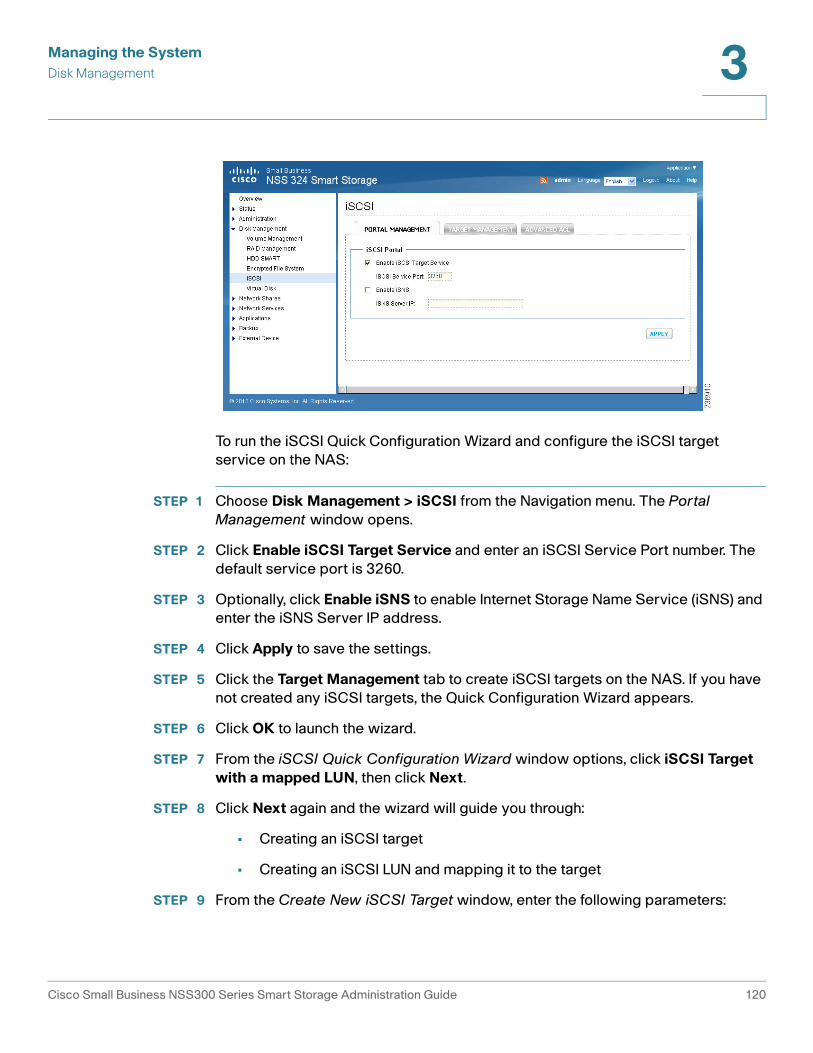
Managing the System
Disk Management 3
To run the iSCSI Quick Configuration Wizard and configure the iSCSI target
service on the NAS:
STEP 1 Choose Disk Management > iSCSI from the Navigation menu. The Portal
Management window opens.
STEP 2 Click Enable iSCSI Target Service and enter an iSCSI Service Port number. The
default service port is 3260.
STEP 3 Optionally, click Enable iSNS to enable Internet Storage Name Service (iSNS) and
enter the iSNS Server IP address.
STEP 4 Click Apply to save the settings.
STEP 5 Click the Target Management tab to create iSCSI targets on the NAS. If you have
not created any iSCSI targets, the Quick Configuration Wizard appears.
STEP 6 Click OK to launch the wizard.
STEP 7 From the iSCSI Quick Configuration Wizard window options, click iSCSI Target
with a mapped LUN, then click Next.
STEP 8 Click Next again and the wizard will guide you through:
• Creating an iSCSI target
• Creating an iSCSI LUN and mapping it to the target
STEP 9 From the Create New iSCSI Target window, enter the following parameters:
Cisco Small Business NSS300 Series Smart Storage Administration Guide 120

Managing the System
Disk Management 3
iSCSI Target Profile:
• Target Name—Enter the target name for the iSCSI storage resource.
• Target Alias—Enter the target alias for the iSCSI storage resource.
CRC/Checksum (Optional):
• Data Digest—Click to use the data digest procedure when identifying and
verifying the checksum.
• Header Digest—Click to use the header digest procedure when identifying
and verifying the checksum.
STEP 10 Click Next to continue to the authentication settings.
STEP 11 From the CHAP Authentication Settings window, enter the following parameters:
• Use CHAP authentication—Select to enable CHAP authentication. Using
CHAP authentication, only the iSCSI target authenticates the initiator. For
example, the initiators have to enter the user name and password setting
here to access the target.
• User Name—Enter the user name for CHAP authentication. Maximum
length is 256 characters.
• Password—Enter the password. Maximum length is 12-16 characters.
• Re-enter Password—Re-enter the password for verification.
• Mutual CHAP—Click to use the CHAP two-way authentication protocol
between the iSCSI target and initiator. The target authenticates the initiator
using the first set of username and password. The initiator authenticates the
target using the mutual CHAP settings.
• User Name—Enter the initiator user name for the mutual CHAP
authentication. Maximum length is 12-16 characters.
• Password—Enter the password. Maximum length is 12-16 characters.
• Re-enter Password—Re-enter the password for verification.
STEP 12 Click Next to create an iSCSI LUN. An iSCSI LUN is a logical volume mapped to the
iSCSI target.
STEP 13 From the Create an iSCSI LUN window, configure the following parameters:
• LUN Allocation—Select one of the following modes to allocate the disk
space to the LUN.
Cisco Small Business NSS300 Series Smart Storage Administration Guide 121

Managing the System
Disk Management 3
- Thin-Provisioning—Select this option to allocate the disk space in a
flexible manner. You can allocate the disk space to the target anytime
regardless of the current storage capacity available on the NAS. Over-
allocation is allowed since the storage capacity of the NAS can be
expanded by online RAID capacity expansion (available in RAID 1, 5, 6).
- Instant Allocation—Select this option to allocate the disk space to the
LUN instantly. This option guarantees the disk space assigned to the LUN
but may take more time to create the LUN.
• LUN Name—Enter the LUN name.
• LUN Location—From the drop-down list, select the LUN location, which is
the disk volume on the NAS.
• Capacity—Enter the capacity for the LUN. Move the slider to increase or
decrease the capacity.
STEP 14 Click Next to confirm the settings.
STEP 15 From the Confirm Settings window, click Next to continue.
STEP 16 When the target and the LUN have been created successfully you will see a
message on the iSCSI Quick Configuration Wizard window. Click Finish.
You can view the target and LUN from the Target Management tab.
STEP 17 Run the iSCSI initiator (Windows PC, Mac, or Linux) and connect to the iSCSI
target (NAS).
After successful logon, format the iSCSI target (disk volume). You can start to use
the disk volume on the NAS as a virtual drive on your computer.
NOTE The NAS supports a maximum of eight iSCSI devices.
Creating Additional LUNs for an iSCSI Target
From the Disk Management > iSCSI > Target Management window, you can
create multiple LUNs for an iSCSI target. The LUNs created can be mapped to and
unmapped from the iSCSI target anytime. You can also unmap the LUN from a
target and map it to another target.
Cisco Small Business NSS300 Series Smart Storage Administration Guide 122

Managing the System
Disk Management 3
To create multiple LUNs:
STEP 1 Choose Disk Management > iSCSI > Target Management from the Navigation
menu. The Target Management window opens.
STEP 2 Click Quick Configuration Wizard to launch the wizard.
STEP 3 From the iSCSI Quick Configuration Wizard window options, click iSCSI LUN
only.
STEP 4 Click Next. The Create an iSCSI LUN window opens.
STEP 5 From the Create an iSCSI LUN window, enter the following parameters:
• LUN Allocation—Select one of the following modes to allocate the disk
space to the LUN.
- Thin-Provisioning—Select this option to allocate the disk space in a
flexible manner. You can allocate the disk space to the target anytime
regardless of the current storage capacity available on the NAS. Over-
allocation is allowed since the storage capacity of the NAS can be
expanded by online RAID capacity expansion (available in RAID 1, 5, 6).
- Instant Allocation—Select this option to allocate the disk space to the
LUN instantly. This option guarantees the disk space assigned to the LUN
but may take more time to create the LUN.
• LUN Name—Enter the LUN name.
Cisco Small Business NSS300 Series Smart Storage Administration Guide 123

Managing the System
Disk Management 3
• LUN Location—From the drop-down list, select the LUN location, which is
the disk volume on the NAS.
• Capacity—Enter the capacity for the LUN. Move the slider to increase or
decrease the capacity.
STEP 6 Click Next. The Map to Target window opens.
STEP 7 From the Map to Target window, you can select the target to map the LUN to. This
is optional. You can also select not to map the LUN now and map it at a later time.
The parameters are:
• Do not map it to a target for now—Select to not map the LUN to a target.
• Target Alias/Taget IQN—Select the target to map the LUN to.
STEP 8 Click Next to confirm the settings, then click Next again to continue.
STEP 9 When the LUN has been created successfully, you will see a message on the
iSCSI Quick Configuration Wizard window. Click Finish.
You can view the target list and unmapped LUN list from the Target Management
tab.
In the Target Management window, the status is displayed for the iSCSI target and
LUN. The following table provides the various status descriptions.
Item Status Description
iSCSI Target Ready The iSCSI target is ready but no
initiator has connected to it yet.
Connected The iSCSI target has been
connected by an initiator.
Disconnected The iSCSI target has been
disconnected.
Offline The iSCSI target has been
deactivated and cannot be
connected by the initiator.
Cisco Small Business NSS300 Series Smart Storage Administration Guide 124

Managing the System
Disk Management 3
In the Target Management window, there are a number of actions that you can
perform as described below:
Action Icons
LUN Enabled The LUN is active for connection
and is visible to authenticated
initiators.
Disabled The LUN is inactive and is invisible
to the initiators.
Action Description
Deactivate Click this icon to deactivate a ready or connected target.
Note that the connection from the initiators will be
removed.
Activate Click this icon to activate an offline target.
Modify Click this icon to modify the target settings, such as target
alias, CHAP information, and checksum settings.
Click this icon to modify the LUN settings, such as LUN
allocation, name, and disk volume directory.
Delete Click this icon to delete an iSCSI target. All the
connections will be removed.
Disable Click this icon to disable a LUN. All the connections will be
removed.
Enable Click this icon to enable a LUN.
Unmap Click this icon to unmap the LUN from the target. Note that
you must disable the LUN first before unmapping the LUN.
When you click this icon, the LUN will be moved to the
Un-Mapped iSCSI LUN List.
Map Click this icon to map the LUN to an iSCSI target. This
option is only available from the Un-Mapped iSCSI LUN
List.
Item Status Description
Cisco Small Business NSS300 Series Smart Storage Administration Guide 125

Managing the System
Disk Management 3
Switch the Mapping of a LUN
From the Disk Management > iSCSI > Target Management window, you can
unmap a LUN from the iSCSI target and map it to another target.For the icons
referred to in these steps, refer to Action Icons, page 125.
To switch the mapping of a LUN.
STEP 1 Choose Disk Management > iSCSI > Target Management from the Navigation
menu. The Target Management window opens.
STEP 2 Select a LUN to unmap from an iSCSI target and click the Disable icon.
STEP 3 Click the Unmap icon to unmap the LUN. The LUN will appear in the Un-Mapped
iSCSI LUN List.
STEP 4 Click the Map icon to map the LUN to another target.
STEP 5 Select the target to map the LUN to and click Apply. The LUN is mapped to the
target.
After creating the iSCSI targets and LUN on the NAS, you can use the iSCSI
initiator installed on your computer (Windows PC, Mac, or Linux) to connect to the
iSCSI targets and LUN and use the disk volumes as the virtual drives on your
computer.
Advanced ACL
From the Disk Management > iSCSI > Advanced ACL window, you can create a
LUN masking policy to configure the permission of the iSCSI initiators that attempt
to access the LUN mapped to the iSCSI targets on the NAS.
View Click this icon to view the connection status of an iSCSI
target.
Action Description
Cisco Small Business NSS300 Series Smart Storage Administration Guide 126

Managing the System
Disk Management 3
To create a LUN masking policy:
STEP 1 Choose Disk Management > iSCSI > Advanced ACL from the Navigation menu.
The Advanced ACL window opens.
STEP 2 Click Add a Policy.
STEP 3 From the Add a Policy window, enter the policy name, the initiator IQN, and assign
the access right for each LUN created on the NAS.
NOTE To find the initiator IQN, start Microsoft iSCSI initiator and click the General tab. The
initiator IQN is listed in the Initiator Node Name field.
• Name—Displays LUN name.
• Read Only—The connected initiator can only read the data from the LUN.
• Read/Write—The connected initiator has read and write access to the LUN.
• Deny Access—The LUN is invisible to the connected initiator.
If no LUN masking policy is specified for a connected iSCSI initiator, the default
policy is applied. The default policy allows read and write access from all the
connected iSCSI initiators. You can click the Edit icon on the LUN masking list to
edit the default policy.
NOTE Make sure you have created at least one LUN on the NAS before editing the default
LUN policy.
Cisco Small Business NSS300 Series Smart Storage Administration Guide 127

Managing the System
Disk Management 3
Connect to the iSCSI Targets with Microsoft iSCSI Initiator on Windows
Before you start to use the iSCSI target service, make sure you have created an
iSCSI target with a LUN on the NAS and installed the correct iSCSI initiator for
your operating system.
iSCSI initiator on Windows
If you are using Windows Vista, Windows 7, or Windows Server 2008, Microsoft
iSCSI software initiator is included. For all other Windows versions, you will need
to install additional software. For more information see:
http://www.microsoft.com/downloads/details.aspx?familyid=12cb3c1a-15d6-
4585-b385-befd1319f825&displaylang=en
To configure Microsoft iSCSI Initiator on Windows:
STEP 1 In Windows, start iSCSI initiator from Control Panel > Administrative Tools.
STEP 2 From the iSCSI Initiator Properties window, click the Discovery tab, then click
Discover Portal. The Discover Target Portal window opens.
STEP 3 Enter the NAS IP address and the port number for the iSCSI service.
STEP 4 Click OK.
STEP 5 From the iSCSI Initiator Properties window, click the Targets tab. The available
iSCSI targets and their status are shown.
STEP 6 Select the target you want to connect and click Connect. The Connect To Target
window opens.
STEP 7 Check the check box to add this connection to the list of Favorite Targets.
STEP 8 Click Advanced to specify the logon information if you have configured the
authentication. Otherwise, click OK to continue.
Upon successful logon, the status of the target shows as Connected.
After the target is connected, Windows will detect it’s presence and treat it as if
there is a new hard disk drive added that needs to be initialized and formatted
before it can be used.
STEP 9 Right-click My Computer > Manage. The Computer Management window opens.
STEP 10 Choose Storage > Disk Management from the left panel. A window displays
automatically and ask if you want to initialize the newly found hard drive.
STEP 11 Click OK and format this drive as you usually would when adding a new disk.
Cisco Small Business NSS300 Series Smart Storage Administration Guide 128

Managing the System
Disk Management 3
After disk initialization and formatting, the new drive is attached to your computer.
You can now use this iSCSI target as a regular disk partition.
Connect to the iSCSI Targets with Xtend SAN iSCSI Initiator on Mac OS
This section shows you how to use Xtend SAN iSCSI Initiator on the Mac OS to
add the iSCSI target (NAS) as an extra partition. Before you start to use the iSCSI
target service, make sure you have created an iSCSI target with a LUN on the NAS
and installed the correct iSCSI initiator for your OS.
About Xtend SAN iSCSI initiator
ATTO's Xtend SAN iSCSI Initiator for Mac OS X allows Mac users to utilize and
benefit from iSCSI. It is compatible with Mac OS X 10.4.x to 10.6.x. For more
information, see:
http://www.attotech.com/products/product.php?sku=INIT-MAC0-001
For the Xtend SAN iSCSI Initiator download, there might be a charge for this
software. For freeware, you can check the global SAN iSCSI initiator released by
Studio Network Solutions (SNS).
NOTE After installing Xtend SAN iSCSI initiator, you can locate it in Places > Applications.
To use Xtend SAN iSCSI initiator on Mac:
STEP 1 In your Mac OS, choose Places > Applications > Xtend SAN.
STEP 2 Click the Discover Targets tab.
STEP 3 Choose either Discover by DNS/IP or Discover by iSNS depending on the
network topology. In this example, the IP address is used to discover the iSCSI
targets.
STEP 4 In the Discover Targets window, enter the following parameters:
• Address—Enter the NAS IP address.
• Port—Enter the iSCSI target port number. The default port number is 3260.
• CHAP—If applicable, enter the CHAP authentication information.
- Target User Name—Enter the target user name for CHAP authentication.
- Target Secret—Enter the target secret key for CHAP authentication.
Cisco Small Business NSS300 Series Smart Storage Administration Guide 129

Managing the System
Disk Management 3
- Mutual Authentication—Check the check box to use the CHAP two-way
authentication protocol between the iSCSI target and initiator. The target
authenticates the initiator using the first set of username and password.
The initiator authenticates the target using the mutual CHAP settings.
- Initiator User Name—Enter the initiator user name for the mutual CHAP
authentication.
- Initiator Secret—Enter the initiator secret key for the mutual CHAP
authentication.
STEP 5 Click Finish. All the available iSCSI targets on the NAS will be shown. Select the
target you want to connect and click Add.
STEP 6 Click the Setup tab to configure the connection properties of the selected iSCSI
target.
STEP 7 Click the Status tab and select the target to connect. Then click Login to proceed.
The first time you login to the iSCSI target, a window displays automatically to
remind you the disk is not initialized.
STEP 8 Click Initialize… to format the disk. You can also perform the initialization from the
Disk Utilities application.
You can now use the iSCSI target as an external drive on your Mac.
Connect to the iSCSI Targets with Open-iSCSI Initiator on Linux
This section shows you how to use Linux Open-iSCSI Initiator on Ubuntu to add
the iSCSI target (NAS) as an extra partition. Before you start to use the iSCSI
target service, make sure you have created an iSCSI target with a LUN on the NAS
and installed the correct iSCSI initiator for your operating system.
About Linux Open-iSCSI Initiator
The Linux Open-iSCSI Initiator is a built-in package in Ubuntu 8.04 LTS or later. You
can connect to an iSCSI volume at a shell prompt with a few commands. For more
information about Ubuntu, see:
http://www.ubuntu.com/
To download Open-iSCSI see:
http://www.open-iscsi.org/
Cisco Small Business NSS300 Series Smart Storage Administration Guide 130

Managing the System
Disk Management 3
Before you start
Install the Open-iSCSI package. The package is also known as the Linux Open-
iSCSI Initiator.
To install the Open-iSCSI package, type the following command:
# sudo apt-get install open-iscsi
To connect to an iSCSI target (NAS) with Linux Open-iSCSI Initiator:
STEP 1 You might need to modify the iscsid.conf for CHAP logon information, such as
node.session.auth.username and node.session.auth.password. Type the following
command:
# vi /etc/iscsi/iscsid.conf
STEP 2 Save and close the file. Then restart the open-iscsi service using the following
command:
# /etc/init.d/open-iscsi restart
STEP 3 Discover the iSCSI targets on a specific host (the NAS in this example). For
example, IP address is 10.8.12.31 and a default port number 3260.
# iscsiadm -m discovery -t sendtargets -p 10.8.12.31:3260
STEP 4 Check the available iSCSI node(s) to connect.
# iscsiadm -m node
You can delete the node(s) you don’t want to connect to when the service is on
with the following command:
# iscsiadm -m node --op delete --targetname THE_TARGET_IQN
STEP 5 Restart open-iscsi to login to all the available nodes.
# /etc/init.d/open-iscsi restart
You should see the login message as: Login session [iface: default, target:
iqn.2004-04.com:NAS:iSCSI.ForUbuntu.B9281B, portal: 10.8.12.31,3260] [ OK ]
STEP 6 Check the device status with dmesg.
# dmesg | tail
STEP 7 Enter the following command to create a partition. In this example, /dev/sdb is the
device name.
Cisco Small Business NSS300 Series Smart Storage Administration Guide 131

Managing the System
Disk Management 3
# fdisk /dev/sdb
STEP 8 Format the partition using the following command:
# mkfs.ext3 /dev/sdb1
STEP 9 Mount the file system using these two commands:
# mkdir /mnt/iscsi
# mount /dev/sdb1 /mnt/iscsi/
STEP 10 You can test the I/O speed using the following command:
# hdparm -tT /dev/sdb1
STEP 11 Below are some “iscsiadm” related commands:
Discover the targets on the host:
# iscsiadm -m discovery --type sendtargets --portal HOST_IP
Login to a target:
# iscsiadm –m node --targetname THE_TARGET_IQN --login
Logout a target:
# iscsiadm –m node --targetname THE_TARGET_IQN --logout
Delete a target:
# iscsiadm –m node --op delete --targetname THE_TARGET_IQN
Virtual Disk
The Virtual Disk (VD) is based on iSCSI technology, which makes it become the
stack master and can connect to the other stack targets. With the VD, you can
expand the capacity of your NAS and use it as the system disk volume(s). In
addition, you can create disk shares and use them for data exchange, storage and
backup, just like the local disk shares.
NOTE This function and its content is only applicable on some NAS models.
Each virtual disk drive will be recognized as a single logical volume in the local
system.
Cisco Small Business NSS300 Series Smart Storage Administration Guide 132

Managing the System
Network Shares 3
To add a virtual disk:
STEP 1 Choose Disk Management > Virtual Disk from the Navigation menu. The Virtual
Disk window opens.
STEP 2 Click Add Virtual Disk.
STEP 3 Enter the target server IP and port number (default: 3260). Click Get Remote Disk.
If authentication is required, enter the user name and password. Then, click Apply.
STEP 4 When the status of the virtual disk is “Ready,” you can start to use the virtual disk
as a disk volume of the NAS.
The NAS supports a maximum of eight virtual disks.
Network Shares
This section describes creating network share folders and editing the access
rights of users and user groups. The following topics are included:
• Share Folders
• Quota
Share Folders
The primary purpose of a network share is for sharing files over a network. Under
a standard operating environment you can create different network shares for
various file types and provide different access rights to users or user groups to
shared folders. Several default network shares are created during system
initialization and installation.
Cisco Small Business NSS300 Series Smart Storage Administration Guide 133

Managing the System
Network Shares 3
Action Icons
In the Share Folders window there are a number of actions that you can perform
on each share folder as described below.
Action Icon Description
Property Click this icon to edit the share folder property, including
disk volume, hide network drive, lock file, path, comment,
and enable write-only FTP access.
Access
Control
Click this icon to edit the access right of the users and
user groups to the share folder.
NFS
Access
Control
Click this icon to edit the NFS access right of the share
folder. See NFS Access Control, page 135.
WebDAV
Access
Control
Click this icon to edit the WebDAV (Web-based
Distributed Authoring and Versioning) access control of
the share folder. You can edit the WebDAV access right of
the local users and local groups, and edit the access rights
of guests who could remotely access the share folders by
web browser. To use this function, you must enable
WebDAV and Web server from the Network Services >
Web Server window. See WebDAV Access Control,
page 136.
Cisco Small Business NSS300 Series Smart Storage Administration Guide 134
Managing the System
Network Shares 3
NFS Access Control
You can set the NFS access rights for a network share as described in the table
below. If you select No limit or Read only, you can specify the IP address or
domains that are allowed to connect to the share folder by NFS.
The format of an allowed IP address or domain name is shown below:
• Single server—A valid domain name, IP address, or host name that can be
resolved by a DNS server.
• Use wildcard characters to specify a series of servers—Use “*” or “?” to
specify the string criteria. When you use wildcard characters in a valid host
name, dot (.) is not included in wildcard characters. For example, when you
enter *.example.com, one.example.com is counted while
one.two.example.com is not counted.
• IP network—Can be specified in two formats. The first format is a.b.c.d/x,
where a.b.c.d refers to the network and x refers to number of bits of the
network mask. For example, the IP configuration can be specified as
192.168.0.0/24. The second valid format is a.b.c.d/network mask. In this
case, a.b.c.d refers to the network and the following value refers to the
network mask setting. For example, the same IP configuration can be
specified as192.168.100.8/255.255.255.0.
Refresh Click this icon to refresh the information of the share folder.
NOTE Share Folder status does not update
dynamically. You must click Refresh for the latest
status. By default, the system will automatically
refresh all shares by 2:00 a.m. (0200) based on the
NAS system clock.
Field Description
No Limit Unlimited access allows the user to create, read, write,
and delete files or folders in the network share and any
subfolders.
Read Only Read Only access allows the user to read files in the
network share and any subfolders but denies functions to
write, create, or delete.
Deny Access Denies all access to files and folders in the network share.
Action Icon Description
Cisco Small Business NSS300 Series Smart Storage Administration Guide 135

Managing the System
Network Shares 3
• Network group—Represented as @group-name; group-name refers to the
name of NIS network group.
NOTE Make sure the format you enter is correct. An incorrect format can lead to access
errors.
WebDAV Access Control
You can set up WebDAV folder access controls. WebDAV is a set of extensions to
the HTTP or HTTPS protocol that allows the users to edit and manage files on
remote World Wide Web servers. Users and User Group rights can be set to Full
Access, Deny Access or Read Only. WebDAV access right settings applied to a
folder will be granted to all users who are given access this share folder; they will
share the same access right settings.
Creating New Share Folders or Restoring Default Network Shares
From the Network Shares > Share Folders window you can create new share
folders and also restore default network shares.
To create a new share folder:
STEP 1 Choose Network Shares > Share Folders from the Navigation menu. The Share
Folders window opens.
STEP 2 Click New Share Folder. The Create a Share Folder Wizard opens. Click Next to
continue.
a. Enter a folder name for the share folder.
b. Choose a disk volume for the share folder.
c. Choose whether you want to hide the share folder in My Network Places.
d. Choose whether to lock open files (oplocks) in the share folder.
e. Choose whether to automatically specify a path for the share folder or you can
manually enter a path.
f. Enter a description for the share folder.
g. Click Next.
STEP 3 Select a privilege level and guest access rights for the share folder and click Next.
STEP 4 Select read/write access by user and click Next.
Cisco Small Business NSS300 Series Smart Storage Administration Guide 136

Managing the System
Network Shares 3
STEP 5 A confirm settings window opens, click Next if you agree with the settings or click
Back to change any settings.
STEP 6 Click Finish to exit the Share Folder Wizard.
To restore default network shares:
STEP 1 Choose Network Shares > Share Folders from the Navigation menu. The Share
Folders window opens.
STEP 2 Click Restore Default Network Shares. A dialog asks if you are sure that you
want to restore default network shares. Click OK to continue.
ISO Share Folders
From the Network Shares > Share Folders > ISO Share Folders window, you can
mount the ISO image files on the NAS as ISO share folders and access the
contents without disc burning. The NAS supports mounting up to 256 ISO share
folders.
To mount an ISO file on the NAS:
STEP 1 Choose Network Shares > Share Folders > ISO Share Folders from the
Navigation menu. The ISO Share Folders window opens.
STEP 2 Click Mount An ISO File. The Choose An ISO Image File window opens.
Cisco Small Business NSS300 Series Smart Storage Administration Guide 137

Managing the System
Network Shares 3
STEP 3 From the Source ISO Image File field, select an ISO image file on the NAS.
STEP 4 Click Next and the image file will be mounted as a share folder on the NAS.
STEP 5 In the ISO Share Folder Settings window, enter the following parameters:
• Folder Name—Enter the folder name.
• Hide Folder—Choose Yes to hide the folder. Default is No.
• Description—Enter a description for the folder.
STEP 6 Click Next. The Privilege window opens.
STEP 7 Specify the user access rights to the share folder:
• Grant read-only access right for administrators only—Read only access
for administrators only.
• By User—Access rights to share folder by user.
• By User Group—Access rights to share folder by user group.
STEP 8 Configure the Guest Access Right:
• Deny Access—Deny guest access.
• Read only—Allow read only access for guests.
STEP 9 Click Next.
STEP 10 Confirm the settings and click Next.
STEP 11 The new share folder is created successfully. Click Finish.
After mounting the image file, you can specify the access rights of the users using
different network protocols such as SMB, AFP, NFS, and WebDAV by clicking the
icons in the Action column from the Share Folders tab.
The NAS supports mounting ISO image files using Web File Manager, see Mount
ISO Shares, page 171.
Quota
From the Network Shares > Quota window, you can enable the quota settings for
all the users and specify the quota size they are allowed to use on each disk
volume of the NAS. This function is disabled by default.
Cisco Small Business NSS300 Series Smart Storage Administration Guide 138

Managing the System
Network Shares 3
To enable quota for all users:
STEP 1 Choose Network Shares > Quota from the Navigation menu. The Quota window
opens.
STEP 2 Click Enable quota for all users to enable a quota size to be applied to all users.
STEP 3 Enter a quota size in MB.
Field Description
Enable Quota for
all users
The Quota function is disabled by default. You can activate
this function to manage or allocate disk space for each
user.
Quota size on the
disk
Set quota size for each user's access authorization to the
disk. A user is denied the right to create new files or
directories once the quota size is exceeded. This integer
number entered in the quota field must be greater than 0
and cannot exceed the supported limit up to 2,000,000
MB (2 TB).
Cisco Small Business NSS300 Series Smart Storage Administration Guide 139

Managing the System
Network Services 3
STEP 4 Click Apply. Your Quota settings are updated to the NAS and the quota settings
are shown.
STEP 5 Click Generate to generate a quota settings file in CSV format.
STEP 6 After the file has been generated, click Download to save the file to a specified
location.
NOTE You can change the individual user quote size in Administration > Users > Edit
Account Profile.
Network Services
This section describes the following network services that are supported on the
NAS.
• Microsoft Networking
• Apple Networking
• NFS Service
• FTP Service
• Telnet/SSH
• SNMP Settings
• Web Server
• Remote Access
Microsoft Networking
The NAS device supports Microsoft networking protocols used with home and
business LANs.
Microsoft Windows users must enable Microsoft networking in order to access
the files on network share folders. After enabling this option, you must assign a
workgroup name. The workgroup name must not exceed 15 characters. The
following characters are not supported:
" / \ [ ] : ; | = , + * ? < > ` ' %
Cisco Small Business NSS300 Series Smart Storage Administration Guide 140

Managing the System
Network Services 3
NOTE The first character cannot be a period (.).
The NAS device can be configured as a standalone server or member of the
Windows Active Directory® (AD). AD can centralize the information about users,
groups of users, and computers and manage them in a more advanced network.
Through the network, AD Server can offer other computers and network devices
within the same domain correct account information so that the information system
of the organization can be safer and more convenient.
To enable Microsoft networking:
STEP 1 Choose Network Services > Microsoft Networking from the Navigation menu.
The Microsoft Networking window opens.
STEP 2 Click Enable file service for Microsoft networking to enable Microsoft
networking.
STEP 3 Select either Standalone Server or AD Domain Member networking type and
enter the appropriate parameters according to the the networking type that you
choose.
Cisco Small Business NSS300 Series Smart Storage Administration Guide 141

Managing the System
Network Services 3
• Standalone Server—Use local Users for user authentication.
—OR—
• AD Domain Member—Use a Microsoft AD domain to authenticate users.
Field Description
Server Description
(Optional)
Describe the NAS so that users can easily identify the
server. For example, the name of the administrator or
department, or the location of the server.
Workgroup Specify the workgroup to which the NAS belongs.
Field Description
Server Description
(Optional)
Describe the NAS so that users can easily identify the
server. For example, the name of the administrator or
department, or the location of the server.
Domain NetBIOS
Name
Enter the NetBIOS domain name from the AD Domain
server. To identify the name, from the AD server open a
window from Control Panel > System Properties. The
name that displays in the Domain field is the domain
name. The NetBIOS domain name is the first
occurrence of the domain name. For example, if the
domain name is “Cisco.com, ” the NetBIOS domain
name is “Cisco” without “.com.”
AD Server Name The name of the AD server. To identify the name, from
the AD server open a window from Control Panel >
System Properties.
• A name displays in the title computer name as
the AD server name (Windows 2008 only).
• For Windows 2003, the format display from the
server is different. The AD server name is part
the computer name. Example in Windows 2003:
computer name displays “aaaaaa.bbbbbb.com”
where “aaaaaa” is the AD server name and
“bbbbbb.com” is the domain name.
Cisco Small Business NSS300 Series Smart Storage Administration Guide 142

Managing the System
Network Services 3
STEP 4 Click Apply. Your Microsoft networking settings are updated to the NAS.
Advanced Options
From the Network Services > Microsoft Networking > Advanced Options
window, you can configure advanced settings such as enabling WINS server,
NTLMv2 authentication login for shared folders, and enable trusted domains.
Domain Enter the AD server domain name. To identify the
name, from the AD server open a window from Control
Panel > System Properties. The name that displays in
the Domain field is the domain name.
Organization Unit
(Optional)
Organization Unit provides a unique way to classify
users, groups of users, or computers located in the AD
domain directories. The purpose of Organization Unit
is to differentiate between objects (users, groups of
users, or computers) with the same name, primarily to
parcel out authority to manage objects.
Domain Administrator
Username
Enter the AD domain administrator username to login
to the AD domain server for NAS to import AD user and
group profiles.
Domain Administrator
Password
Enter the AD domain administrator password for AD
domain server authentication.
Field Description
Cisco Small Business NSS300 Series Smart Storage Administration Guide 143

Managing the System
Network Services 3
To configure advanced options:
STEP 1 Choose Network Services > Microsoft Networking > Advanced Options from
the Navigation menu. The Advanced Options window opens.
STEP 2 Click Enable WINS server to allow the NAS AD configuration to support WINS
server functionality.
STEP 3 If there is an existing WINS server on your network and your workstation is
configured to use that WINS server for name resolution, you must specify your
WINS server IP address on the NAS. Click the check box Use the specified WINS
server to enable the specified WINS server and enter the WINS server IP address.
STEP 4 Click Local Master Browser to make the NAS responsible for keeping track of
computers available on the network or the computers that have announced
themselves as master browser for offering services.
NOTE Do not set this NAS to be the domain master if a Windows system is
already set as the domain master within your network.
STEP 5 Click Allow only NTLMv2 authentication to require login to the shared folders
only with NTLMv2 authentication. If the option is turned off, NTLM (NT LAN
Manager) will be used by default and NTLMv2 can be negotiated by the client.
The default setting is disabled.
Cisco Small Business NSS300 Series Smart Storage Administration Guide 144

Managing the System
Network Services 3
STEP 6 From the Name Resolve Priority drop-down list, DNS is used for name resolution
by default.
STEP 7 Click Login style: DOMAIN\USERNAME instead of DOMAIN+USERNAME for
FTP, AFP, and Web File Manager to enable users to use the same login name
format (domain\username) to connect to the NAS via AFP, FTP, and Web File
Manager.
STEP 8 When you click Automatically register in DNS and the NAS is joined to an Active
Directory, the NAS will register itself automatically in the domain DNS server. This
will create a DNS host entry for the NAS in the DNS server. If the NAS IP address
is changed, the NAS will automatically update the new IP address in the DNS
server.
STEP 9 Click Enable Trusted Domains to enable trusted domains.
STEP 10 Click Apply. Your advanced option settings are updated to the NAS.
Apple Networking
From the Network Services > Apple Networking window, Apple Macintosh users
can enable Apple Networking in order to access network shares via the Apple File
Protocol (AFP).
If your NAS is a member of an AppleTalk network that includes an extended
network assigned with multiple zones, assign a zone name. The zone name must
not exceed 15 characters. The following characters are not supported:
" / \ : | ? < > . %
If you do not wish to assign a network zone, enter an asterisk (*). The asterisk (*) is
the default setting.
Cisco Small Business NSS300 Series Smart Storage Administration Guide 145

Managing the System
Network Services 3
To enable Apple networking:
STEP 1 Choose Network Services > Apple Networking from the Navigation menu. The
Apple Networking window opens.
STEP 2 Click Enable Apple Filing Protocol to enable Apple networking.
STEP 3 Click Apply. Your Apple networking settings are updated to the NAS.
NFS Service
From the Network Services, NFS Service window, Linux users can enable NFS
Service to support file access by Linux servers.
Cisco Small Business NSS300 Series Smart Storage Administration Guide 146

Managing the System
Network Services 3
To enable NFS service:
STEP 1 Choose Network Services > NFS Service from the Navigation menu. The NFS
Service window opens.
STEP 2 Click Enable NFS Service to enable NFS service.
NOTE For virtualization environment, it is recommended that you disable the write cache
function in the Administration > Hardware dialog box. Default is disabled.
STEP 3 Click Apply. Your NFS service settings are updated to the NAS.
Cisco Small Business NSS300 Series Smart Storage Administration Guide 147

Managing the System
Network Services 3
FTP Service
FTP clients can have access to network share folders on the NAS device.
To enable FTP service:
STEP 1 Choose Network Services > FTP Service from the Navigation menu. The FTP
Service window opens.
STEP 2 Click Enable FTP Service to enable FTP service.
STEP 3 Select at least one FTP transfer protocol type:
• FTP (standard)—Use general FTP protocol.
• FTP with SSL/TLS (Explicit)—Use SSL or TLS Explicit encryption
protocol.
STEP 4 Enter a port number for FTP service. The default is 21.
STEP 5 You can enable or disable Unicode Support by clicking Yes (enabled) or No
(disabled) in the Unicode Support field. The default setting is No. If your FTP client
Cisco Small Business NSS300 Series Smart Storage Administration Guide 148

Managing the System
Network Services 3
does not support Unicode, select No for Unicode Support and select a supported
filename encoding from Administration > General Settings so that folders and
files can be displayed correctly.
STEP 6 You can enable or disable anonymous login to the FTP site by clicking Yes
(enabled) or No (disabled) in the Enable Anonymous field. The default setting is No.
STEP 7 Enter the FTP Connection parameters:
• Maximum number of all FTP connections—Maximum number of clients
that can be connected at the same time. The upper limit is 256.
• Maximum Number of Connections for a Single Account—Maximum
number of connections for a single account. The upper limit is 256.
• Enable FTP transfer limitation—Click to set the values for FTP transfer
limitation.
- Maximum upload rate (KB/s)—Enter the maximum upload value.
- Maximum download rate (KB/s)—Enter the maximum download value.
STEP 8 Enter Advanced FTP parameters:
• Passive FTP Port Range—You can use the default port range (55536-
56559) or define a port range higher than 1024.
• Respond with external IP address for passive FTP connection request—
You can enable this function when a remote computer is not able to connect
to the FTP server using a WAN connection where the FTP server is behind a
router/firewall. When this function is enabled the FTP server returns the
manually specified IP address or automatically detects the external IP
address so that the remote computer can connect to the FTP server
successfully.
STEP 9 Click Apply. Your FTP service settings are updated to the NAS.
Cisco Small Business NSS300 Series Smart Storage Administration Guide 149

Managing the System
Network Services 3
Telnet/SSH
From the Network Services > Telnet/SSH window, you can allow access to the
NAS using a Telnet or SSH connection.
NOTE Only the “admin” account can login remotely. User with administrator privileges is
not allowed to login remotely.
To enable Telnet/SSH remote login:
STEP 1 Choose Network Services > Telnet/SSH from the Navigation menu.
The Telnet/SSH window opens.
STEP 2 Click Allow Telnet connection to enable Telnet/SSH remote login.
STEP 3 Enter a Port Number for Telnet. The default port is 23.
STEP 4 Click Allow SSH connection to enable SSH connection.
STEP 5 Enter a Port Number for SSH connection. The default value is 22.
STEP 6 Click Enable SFTP to use SFTP, known as SSH File Transfer Protocol or Secure
File Transfer Protocol.
STEP 7 Click Apply. Your Telnet/SSH settings are updated to the NAS.
Cisco Small Business NSS300 Series Smart Storage Administration Guide 150

Managing the System
Network Services 3
SNMP Settings
From the Network Services > SNMP Settings window, you can configure Simple
Network Management Protocol (SNMP), which is widely used in network
management systems to monitor appliances attached to a network such as a NAS.
You can set up SNMP traps to be alerted via SNMP. You can enter up to three
SNMP trap addresses. In addition, you can also select the system event log level in
SNMP.
To enable SNMP service:
STEP 1 Choose Network Services > SNMP Settings from the Navigation menu. The
SNMP Settings window opens.
STEP 2 Click Enable SNMP Service to enable SNMP service.
STEP 3 Enter a Port Number for SNMP service. The default value is 161.
STEP 4 Click SNMP Trap Level types. You can choose from Information, Warning, and
Error event log types.
STEP 5 Specify up to three SNMP trap addresses in the Trap Address fields.
STEP 6 Select an SNMP version. You can choose from SNMP V1/V2 or SNMP V3.
STEP 7 Specify an SNMP community in the Community field.
Cisco Small Business NSS300 Series Smart Storage Administration Guide 151

Managing the System
Network Services 3
STEP 8 Click Apply. Your SNMP settings are updated to the NAS.
STEP 9 To install the SNMP MIB to your managing systems, click Download and save the
file.
The MIB is a type of database in ASCII text format that is used to manage the NAS
in the SNMP network. The SNMP manager uses the MIB to determine the values or
understand the messages sent from the agent (NAS) within the network. You can
download the MIB and view it with any word processor or text editor.
Web Server
From the Network Services > Web Server window, you can enable Web Server
and create a web page that is viewable either locally or on a public network. To
access the NAS using a web browser, enable Web File Manager. See Web File
Manager, page 164.
Cisco Small Business NSS300 Series Smart Storage Administration Guide 152

Managing the System
Network Services 3
To enable web server:
STEP 1 Choose Network Services > Web Server from the Navigation menu. The Web
Server window opens.
STEP 2 Click Enable Web Server to enable the web server.
STEP 3 Enter a Port Number for the web server. The default value is 80.
STEP 4 Enable or disable register_globals by clicking On (enable) or Off (disable). The
setting is disabled by default. When the web program asks to enable PHP
register_globals, enable register_globals. However, for system security concerns,
it is recommended that this option be disabled when possible.
STEP 5 Enable SSL if a secure connection is needed by clicking Enable Secure
Connection (SSL). After enabling this option, users can access websites which
are hosted on the NAS over SSL. The concept of HTTPS is a combination of the
HTTP with the SSL/TLS to create a secure channel over the network.
STEP 6 Enable WebDAV (Web-based Distributed Authoring and Versioning) if needed by
clicking Enable WebDAV. WebDAV is a set of extensions to HTTP that allows users
to edit and manage files collaboratively on remote World Wide Web servers. After
enabling this function, you can access shared folders remotely through a client
application.
NOTE Go to Network Shares > Share Folders for detailed privilege settings.
STEP 7 Enable php.ini if necessary by clicking php.ini Maintenance. The php.ini file is the
system configuration file for the Web Server. After enabling this function, you can
edit, upload or restore this file. It is recommended that you use the system default
setting.
STEP 8 Click Apply. Your web server settings are updated to the NAS.
Virtual Host
Virtual host is a web server function that provides the capability to host more than
one domain (website) on one physical host. You can host multiple websites on the
NAS with this feature. The maximum number of websites that you can host with
virtual host is 32.
Cisco Small Business NSS300 Series Smart Storage Administration Guide 153

Managing the System
Network Services 3
The information provided in the table below is used in the examples as a reference
guide only.
Before you begin, make sure you have completed the following items:
• Web Server—Enable Web Server in Network Services > Web Server.
• DNS Records—The host name must point to the WAN IP of your NAS and
you can normally configure this from your DNS service providers.
• Port Forwarding—If the web server listens on port 80, you need to
configure port forwarding on your router to allow inbound traffic from port
80 to the LAN IP (10.8.12.45) of your NAS.
• SSL Certificate Import—If you are going to enable SSL connection for the
website and intend to use your own trusted SSL certificates, you can import
the certificate from the administration backend in Administration > Security
> SSL Secure Certificate and Private Key.
Host Name WAN/LAN IP
and Port
Document Root Demo Web
Application
site1.mysite.com WAN IP:
111.222.333.444
LAN IP (NAS):
10.8.12.45
Port (NAS): 80
/Web/site1_mysite Joomla
site2.mysite.com /Web/site2_mysite WordPress
www.mysite2.com /Web/www_mysite2 phpBB3
Cisco Small Business NSS300 Series Smart Storage Administration Guide 154

Managing the System
Network Services 3
To use virtual host, follow these steps:
STEP 1 Choose Network Services > Web Server > Virtual Host from the Navigation
menu. The Virtual Host window opens.
STEP 2 Click Enable Virtual Host. After enabling virtual host, you can create multiple
websites by uploading web files to each folder.
STEP 3 Click Apply.
STEP 4 Click Create New Virtual Host. The Create New Virtual Host window opens.
STEP 5 Enter the following parameters:
• Host Name—Enter the host name. For example, site1.mysite.com.
• Folder Name—Specify the folder (in the Web directory) where the web files
will be uploaded to. For example, site1.mysite.
• Protocol:
• HTTP—Click to specify HTTP protocol for the connection.
• HTTPS—Click to specify HTTPS protocol for the connection. If you
select HTTPS, verify that the option Enable Secure Connection (SSL) is
enabled in Network Services > Web Server.
• Port—Enter the port number for the connection.
• Action—Click the Property icon to open the Modify Virtual Host window
and reconfigure the current settings.
STEP 6 Click Apply.
STEP 7 Continue to enter the information for the remaining sites you want to host on the
NAS. Create a folder for each website (For example, site1_mysite, site2_mysite,
and www_mysite2).
STEP 8 Start transferring the website files to the corresponding folders. For example:
• Transfer the Joomla files to site1_mysite
• Transfer the phpBB3 files to site2_mysite
• Transfer the WordPress files to www_mysite2.com
STEP 9 When the files transfer is complete, point your web browser to the websites. Use
http or https, depending on your connection settings:
Cisco Small Business NSS300 Series Smart Storage Administration Guide 155

Managing the System
Network Services 3
http://NAS_host_name
OR
https://NAS_host_name
In this example, the URLs are:
• http://site1.mysite.com
• http://site2.mysite.com
• http://www.mysite2.com
For this example, you would see the Joomla, phpBB3, and WordPress web pages
respectively.
Remote Access
From the Network Services > Remote Access window, you can activate Cisco
Access Now. Cisco Access Now is the secure, easy-to-use way to access and
manage your Smart Storage NAS devices from anywhere.
The process for activating and managing NAS using Cisco Access Now is:
• Create an account—Setup a Cisco Access Now account.
• Register your device—Associate Smart Storage to your Cisco Access
Now account.
• Access from anywhere—Visit www.ciscoaccessnow.com from a web
browser to securely access your devices.
This section includes the following:
• Cisco Access Now Specifications
• Creating a Cisco Access Now Account and Registering Your NAS
• Accessing Your NAS From Anywhere
• Previewing or Modifying the Remote Access Settings
Cisco Small Business NSS300 Series Smart Storage Administration Guide 156

Managing the System
Network Services 3
Cisco Access Now Specifications
The following table provides the Cisco Access Now specifications.
Creating a Cisco Access Now Account and Registering Your NAS
To activate the remote access network service, you need to create a Cisco
Access Now account and register your NAS device(s) to the account.
NOTE The Cisco Access Now account is different than a Cisco.com account. If you
already have a Cisco.com account, that account will not work for Cisco Access
Now.
Web Browser and Mobile Access Cisco Access Now
Web/Mobile connections per day 10
Web/Mobile connection time per session 30 minutes
Local connections Unlimited
Simultaneous Web/Mobile device connections 1
Cisco Small Business NSS300 Series Smart Storage Administration Guide 157

Managing the System
Network Services 3
To create a Cisco Access Now account and register your NAS:
STEP 1 Choose Network Services > Remote Access from the Navigation menu. The
Remote Access window opens.
STEP 2 Click Activate Cisco Access Now.
STEP 3 If you already have a Cisco Access Now account, continue to Step 7. If you do not
have a Cisco Access Now account, in the Create Account section, click New
Registration.
STEP 4 From the Create An Account window, enter the following information:
• Email—Email address for the person who will be using the Cisco Access
Now account.
• Password—Enter a password for the Cisco Access Now account.
• Confirm Password—Re-enter the password for the account.
• Security Question—From the drop-down list, select the security question
that you want to use in the event that you forget the password.
• Security Question Answer—Enter the security question answer that you
will use in the event that you forget the password.
If needed, you can create multiple Cisco Access Now accounts from here.
STEP 5 Click Apply. You will receive a message that the account has been successfully
created. In addition, an email confirming registration is delivered to the email
Cisco Small Business NSS300 Series Smart Storage Administration Guide 158

Managing the System
Network Services 3
address used when creating the account. Save your Cisco Access Now account
details to register your NAS.
STEP 6 Click OK to return to the Remote Access window.
STEP 7 To register the NAS, enter the following information in the Device Registration
section:
• Email—Enter the email address that was used when creating the Cisco
Access Now account.
• Password—Enter the password for the Cisco Access Now account. If you
do not remember the password, click Retrieve Password.
• Device Name—Displays the NAS device name as it will appear on the Cisco
Access Now portal.
STEP 8 Click Register Device to Cisco Access Now, then click OK to continue. A
message displays that the NAS device name has been registered with the Cisco
Access Now service.
NOTE To register multiple NAS devices to your Cisco Access Now account, log into the
NAS device you want to register. Repeat Step 7 and Step 8.
Cisco Small Business NSS300 Series Smart Storage Administration Guide 159

Managing the System
Network Services 3
STEP 9 The Status table displays the following:
• Owner—Email address associated with the registered NAS device and the
Cisco Access Now account.
• State—Active or Inactive.
• User Level—Basic or Pro. For more information about user levels, see
www.ciscoaccessnow.com/service-plans.
• Last Session—Email address for the last user that connected to the NAS
from the Cisco Access Now website.
• Device ID—NAS device ID registered the system MAC address with Cisco
Access Now.
To preview or make any modification to the remote access settings, click the
Cisco Access Now link. You are redirected to the Cisco Access Now web site and
will need to log in with your email and password. If you have multiple NAS devices
registered, you will see a list showing all of your registered devices and other
devices that you are able to access. See Previewing or Modifying the Remote
Access Settings, page 162.
STEP 10 To troubleshoot network communication between the NAS and Cisco Access
Now, click Diagnostics . Use the diagnostic tool if the device failed to register or is
unable to access remotely via the web. In the Diagnostics window, connectivity
information is displayed. Click Finish to exit the Diagnostics tool.
STEP 11 In the Management section, the following options are available:
• Suspend—To suspend your NAS device from Cisco Access Now service,
click Suspend. Click OK from the confirmation window if you are
suspending the service. When the service is suspended and your NAS
device is already registered for service, remote access through Cisco
Access Now is not possible.
• Reset—Click to clear the configuration and reset the Cisco Access Now
service on the NAS so it can recover from a failed registration or other
incorrectly configured states. The device name will be cleared. The email
and password will not be cleared.
Cisco Small Business NSS300 Series Smart Storage Administration Guide 160

Managing the System
Network Services 3
STEP 12 In the Management section, the following options are available after your NAS
device is suspended:
• Resume—To resume the Cisco Access Now service, click Resume. If your
NAS device is already registered to Cisco Access Now, your service will
resume. If your NAS device was not registered to Cisco Access Now before
you suspended service, you will need to register the NAS device for remote
access service.
• Deactivate—To disable the remote access feature from the NAS device,
click Deactivate.
Accessing Your NAS From Anywhere
You can securely access your NAS from a web browser anywhere, anytime. From
the web browser you can launch the Smart Storage GUI the same as if you were
accessing the NAS locally.
The following operating systems and web browsers are supported:
• Windows XP—IE6, IE7, or Firefox 3.5
• Windows Vista—IE7, IE8, Firefox 3.6
• Windows 7—IE8, Chrome, Firefox 3.6
• Mac OS X 10.5—Firefox 3.5, Safari 4
• Mac OS X 10.6—Firefox 3.6, Safari 5
NOTE Accessing your NAS from a mobile or tablet platform is not supported at this time.
STEP 1 From a web browser, go to www.ciscoaccessnow.com and login using your Cisco
Access Now account email address and password.
• If you forgot your password, click Forgot Password from the login screen to
retrieve the password.
• You can also create a new Cisco Access Now account from the web site.
Click the Create a New Account link to create a new account.
After you successfully login, the NAS devices that are registered to your
Cisco Access Now account are displayed in the My Devices window.
STEP 2 Click the NAS icon to access the device.
Cisco Small Business NSS300 Series Smart Storage Administration Guide 161

Managing the System
Network Services 3
STEP 3 You are prompted to download a Java applet. Click Run to continue. The NAS
login window displays.
STEP 4 From the NAS login window, enter the NAS device username and password with
administrator privilege to access the NAS GUI.
Previewing or Modifying the Remote Access Settings
To preview or modify the remote access settings:
STEP 1 From a web browser, go to www.ciscoaccessnow.com and login using your Cisco
Access Now account email address and password. From the My Devices window,
the NAS devices that you have registered are displayed.
STEP 2 From the drop-down list, you can modify the device display by selecting one of
the following options:
• Show only mine—Display NAS devices registered to you.
• Show only my friends—Display NAS devices that you share with your
friends who also have accounts with Cisco Access Now.
• Show mine and friends—Display your registered NAS devices and the
shared NAS devices with friends who have accounts with Cisco Access
Now.
STEP 3 Click Hide inactive devices to hide any NAS devices that may be powered off,
offline, or deactivated from the Cisco Access Now service.
STEP 4 Click the NAS device name to launch the NAS GUI the same as if you were
accessing the NAS locally. You are prompted to download a Java applet. Click
Run to continue. The NAS login window displays. From the NAS login window,
enter the NAS device username and password.
STEP 5 To share a NAS device, click Share.
NOTE You can only share with email addresses that have signed up for Cisco Access Now
accounts.
a. In Friends Email, enter the Cisco Access Now email address for the person you
would like to invite and share the NAS access.
b. Click Share. The email address is added to the Current Sharing table and the
access privilege is shown. The person with the newly added email address
can now log into www.ciscoaccessnow.com and view the list of shared NAS
devices.
Cisco Small Business NSS300 Series Smart Storage Administration Guide 162

Managing the System
Network Services 3
To delete a shared access, enter the Cisco Access Now email address for the
person you would like to delete and click Delete.
STEP 6 From the drop-down list, select the language you want for the GUI.
STEP 7 To modify or view the NAS device settings, click Settings. The following
parameters are available from the Settings window:
• Device Type—Network Storage
• Manufacturer—Cisco
• Device Identification—NAS identification number.
• New Name—Enter a new name for the NAS device if you want to change
the current NAS device name. Click Rename to confirm.
• Transfer Email—Enter the Cisco Access Now email address that you
would like to transfer the NAS device to. This option is used if you are giving
up the ownership of the NAS device or if you are changing email addresses.
Click Transfer to confirm.
• Reset Security—Click to reset the NAS secure code and restart the NAS.
• Language—From the drop-down menu, select the language for the GUI.
STEP 8 To modify or view account settings, click Account in the lower-right corner of the
window. The following parameters are available from the Account Summary
window:
• Registered Email—Displays the registered email address for the person
using the Cisco Access Now account.
• User Level—Displays current user level as Basic or Pro. For more
information, see www.ciscoaccessnow.com/service-plans.
• Current Password—Enter current password for the Cisco Access Now
account.
• New Password—Enter new password for the Cisco Access Now account.
• Confirm Password—Re-enter the password for the account.
• New Email—Enter new registered email address for the person using the
Cisco Access Now account.
• Confirm Email—Re-enter the new registered email address.
• Language—From the drop-down menu, select the language for the GUI.
Cisco Small Business NSS300 Series Smart Storage Administration Guide 163

Managing the System
Applications 3
STEP 9 Click Home in the lower-right corner of the window to return to the My Devices
window or click Logout in the lower-right to exit.
Applications
This section describes the numerous applications available that expand the NAS
capabilities.
• Web File Manager
• Multimedia Station
• Download Station
• iTunes Server
• UPnP Media Server
• MySQL Server
• PKG Plugins
• Syslog Server
Web File Manager
You have the option of using a web browser to access your files on this NAS. If
your system is connected to the Internet and uses a public IP address, the Web
File Manager allows you to access your files on the NAS using a web browser.
Cisco Small Business NSS300 Series Smart Storage Administration Guide 164

Managing the System
Applications 3
To enable the Web File Manager:
STEP 1 Choose Applications > Web File Manager from the Navigation menu. The Web
File Manager window opens.
STEP 2 Click Enable Web File Manager to enable the Web File Manager.
STEP 3 Click Apply. Your Web File Manager settings are updated to the NAS.
NOTE You must first create a network share before using Web File Manager. After the web
file manager is enabled, it can be accessed from Applications > Web File Manager.
If your NAS is using SSL, you can access Web File Manager from the URL
https://<NAS IP address>:8080/cgi-bin/filemanager/. The default port is 8080.
If your NAS is configured with a different port, you need to use that port value for
access to the Web File Manager application. You need a valid user account to log
into the Web File Manager management GUI.
Cisco Small Business NSS300 Series Smart Storage Administration Guide 165

Managing the System
Applications 3
Accessing the Web File Manager
This section describes how to use the Web File Manager which allows you to
manage the files on your NAS from the Internet.
There are three ways to access the Web File Manager:
• Directly using the Web File Manager URL.
• From the NAS main login window.
• From the administration window.
NOTE You must know the IP address of your NAS to login to the Web File Manager.
To access the Web File Manager from a URL:
STEP 1 From your browser, go to URL http://<IP Address>:8080/cgi-bin/filemanager/.
STEP 2 Enter your Username and Password. The Web File Manager opens.
To access the Web File Manager from the NAS login window:
STEP 1 Enter your Username and Password.
STEP 2 From the Application drop-down list, select Web File Manager.
STEP 3 Click Login. The Web File Manager login window opens.
STEP 4 Enter your Username and Password for the Web File Manager. The Web File
Manager opens.
To access the Web File Manager from the Administration window:
STEP 1 Login to the Administration window.
STEP 2 Choose Web File Manager from the Application drop-down list, located in the top
right corner of the window. The Web File Manager window opens.
STEP 3 If a login window appears, login to the Web File Manager.
Cisco Small Business NSS300 Series Smart Storage Administration Guide 166

Managing the System
Applications 3
Using the Web File Manager
The Web File Manager window is composed of three areas: Directory Tree (labled
Web File Manager), Details, and the Actions area. These are explained in more
detail below.
• Directory Tree—The Directory Tree shows a visual representation of the
files and directories of your NAS. You can expand and collapse the
structure by clicking on the plus (+) and minus (-) icons.
• Details Area—The Details area shows information on the selected file or
directory such as name, size, and permissions.
• Actions Area—The Actions Area is the largest part of the Web File Manager
where you can perform numerous actions on files and directories on your
NAS. These actions are described below.
Actions area
Details area
Directory
Tree
Cisco Small Business NSS300 Series Smart Storage Administration Guide 167

Managing the System
Applications 3
Action Icons
In the Web File Manager window there are a number of actions that you can
perform on files as described below.
Action Icon Description
Parent
Folder
Click to move to the parent folder of the currently selected
file.
Refresh Click to refresh the contents of the current directory.
Upload Click to upload a file into the current directory.
Download Click to download a file or directory from the current
directory.
Create
Folder
Click to create a new folder in the current directory.
Rename Click to rename the currently selected file or directory.
Copy Click to copy the currently selected file or directory.
Move Click to move the currently selected file or directory.
Delete Click to delete the currently selected file or directory.
Cisco Small Business NSS300 Series Smart Storage Administration Guide 168

Managing the System
Applications 3
To upload a file to the current directory:
STEP 1 Click the Upload icon. The Upload to window opens.
STEP 2 Click Browse and select a file. Click Open.
NOTE If Skip is chosen for the Mode, the file will not be copied if another file exists with
the same filename. If Overwrite is chosen for the Mode and if there is a file with the
same filename, then that file will be overwritten.
STEP 3 Click Start. Your files are copied to your NAS.
STEP 4 Click the Refresh icon if you want to see the file in the Actions area.
To download a file from the NAS:
STEP 1 Click the Download icon. The File Download dialog opens.
STEP 2 Click Save and specify a location for the file. Click Save.
To create a new folder on the NAS:
STEP 1 Using the Directory Tree, go to the location where you want the new folder.
STEP 2 Click the Create Folder icon. The Create folder dialog opens.
STEP 3 Enter a name for the new folder and click Ok.
To rename a file or folder on the NAS:
STEP 1 Select the file or folder that you want to rename.
STEP 2 Click the Rename icon. The Rename dialog opens.
STEP 3 Enter a new name for the file or folder and click Ok.
Cisco Small Business NSS300 Series Smart Storage Administration Guide 169

Managing the System
Applications 3
To copy a file or folder on the NAS:
STEP 1 Select the file or folder that you want to copy.
STEP 2 Click the Copy icon. The Copy to dialog opens.
NOTE If Skip is chosen for the Mode, the file will not be copied if another file exists with
the same filename. If Overwrite is chosen for the Mode and if there is a file with the
same filename, then that file will be overwritten.
STEP 3 Enter a new name for the file or folder and click Ok.
To move a file or folder on the NAS:
STEP 1 Select the file or folder that you want to move.
STEP 2 Click the Move icon. The Move to dialog opens.
NOTE If Skip is chosen for the Mode, the file will not be moved if another file exists with
the same filename. If Overwrite is chosen for the Mode and if there is a file with the
same filename, then that file will be overwritten.
STEP 3 Enter a new name for the file or folder and click Ok.
To delete a file on the NAS:
STEP 1 Select the file that you want to delete.
STEP 2 Click the Delete icon. The Delete dialog opens.
STEP 3 Click Yes to verify that you want to delete the file.
Cisco Small Business NSS300 Series Smart Storage Administration Guide 170

Managing the System
Applications 3
Mount ISO Shares
Using Web File Manager, you can mount an ISO file on the NAS as a share folder.
To mount an ISO file on the NAS as a share folder:
STEP 1 Login to the Administration window.
STEP 2 Choose Web File Manager from the Application drop-down list, located in the top
right corner of the window. The Web File Manager window opens.
STEP 3 If a login window appears, login to the Web File Manager.
STEP 4 Locate the ISO file on the NAS. Right-click the file and select Mount ISO from the
menu.
STEP 5 Enter the share folder name and click OK.
STEP 6 Click OK to confirm.
The ISO share folder appears in the share folder list. You can access the contents
of the ISO image file. You can login the NAS web interface with an administrator
account and specify the access rights of the users in Network Shares > Share
Folders. See Share Folders, page 133.
To unmount a share folder:
STEP 1 Login to the Administration window.
STEP 2 Choose Web File Manager from the Application drop-down list, located in the top
right corner of the window. The Web File Manager window opens.
STEP 3 If a login window appears, login to the Web File Manager.
STEP 4 Locate the ISO file on the NAS. Right-click the file and select Unmount from the
menu.
STEP 5 Click Yes to confirm and then click OK to unmount.
Cisco Small Business NSS300 Series Smart Storage Administration Guide 171

Managing the System
Applications 3
Multimedia Station
From the Applications > Multimedia Station window, you can configure the NAS to
share photos, music, or video files over the network. The Multimedia Station is a
web interface that allows you to manage your multimedia files including videos,
music, and photos. Prior to using Multimedia Station, you need to enable web
server on the NAS.
To use the Multimedia Station:
STEP 1 Choose Network Services > Web Server from the Navigation menu. The Web
Server window opens.
STEP 2 Click Enable Web Server and Enable Secure Connection (SSL). The default port
number for the SSL connection is 8081.
STEP 3 Click Apply to save your settings.
STEP 4 Choose Applications > Multimedia Station from the Navigation menu. The
Multimedia Station window opens.
STEP 5 Click Enable Multimedia Station to enable the Multimedia Station. This option is
enabled by default. You can access the Multimedia Station from one of the
following links:
http://<NAS IP address>:80/MSV2/
https://<NAS IP address>:8081/MSV2/
Cisco Small Business NSS300 Series Smart Storage Administration Guide 172

Managing the System
Applications 3
STEP 6 Click Rescan media library to enable rescan media library. This option is enabled
by default.
• Daily Start Time—From the drop-down lists, select the time in hour and
minutes. Hours are displayed in the 24-hour format.
STEP 7 Click Apply. Your Multimedia Station settings are updated to the NAS.
STEP 8 In the Reset admin password section, enter the following:
• Password—new password for the Multimedia admin account.
• Verify Password—re-enter the new password.
STEP 9 Click OK to continue.
STEP 10 The first time you connect to Multimedia Station, enter a new password for the
Multimedia admin account.
STEP 11 Click Submit to continue to the Multimedia Station window. If you have created
user accounts for the previous version of Multimedia Station, you can select Keep
existing user accounts to reserve the user accounts.
NOTE The user accounts (including admin) of Multimedia Station are different from the
system user accounts on the NAS. For security reasons, it is recommended to use
a different password for the Multimedia admin account. The password can be a
maximum of 16 characters. Supported characters are A-Z, az, 0-9, -, !, @, #, $, %, _.
STEP 12 From the Multimedia Station window, click Login in the upper right corner.
STEP 13 Enter the user name with access rights to Multimedia Station and the password.
NOTE If you login as the administrator (admin), you can create new users and configure
other advanced settings.
Multimedia Station consists of Media Center, My Jukebox, and Control Panel.
After the Multimedia Station is enabled, it can be accessed by selecting
Applications > Multimedia Station from the top right corner of the Administration
window. If your NAS is using SSL, you can access Multimedia Station from the URL
https://<NAS IP address>:8081/MSV2. The default port is 8081. If your NAS is
configured with a different port, use that port value for access to the Multimedia
Station application. You need a valid user account to log in to the main
management GUI.
Cisco Small Business NSS300 Series Smart Storage Administration Guide 173

Managing the System
Applications 3
Media Center
The folders and multimedia files of the default network share (.../ Multimedia) for
Multimedia Station are shown in Media Center. You can view or play the
multimedia contents (images, videos, and audio files) on the NAS using your web
browser over LAN or WAN.
Supported File Formats
Action Icons
Content Type Supported File Format
Audio MP3
Image JPG/JPEG, GIF, PNG
(Animation will not be shown for animated GIF files)
Video Playback: FLV, MPEG-4 Video (H.264 + AAC)
Transcode: AVI, MP4, M4V, MPG, MPEG, RM, RMVB,
WMV
(Files will be converted into FLV)
Action Icon Description
Home Click to return to the home directory of Multimedia
Station.
Parent
Directory
Click to return to the parent directory.
Refresh Click to refresh the current directory.
Cisco Small Business NSS300 Series Smart Storage Administration Guide 174

Managing the System
Applications 3
Manage
Album
Click to either create a new album under the current
directory or add new files to this album by copying or
uploading files to this directory.
Action can be performed by administrators only.
Set Album
Cover
Click to set up the album cover for each album/directory
by specifying one photo in this album/directory.
Action can be performed by administrators only.
Cooliris Click to browse your photos in 3-dimensional with
Cooliris. You need to install the Cooliris plug-in for your
browser first. When you click 3D viewing, you are
prompted to download and install Cooliris.
Slide Show Click to start the slide show. You can set up the photo
frame, background music, and animation in the slide
show mode.
Publish Click to publish the selected photos (maximum 5 photos)
to popular social networking sites. Supported sites are
Twitter, Facebook, MySpace, Plurk, Windows Live, and
Blogger.
Action can be performed by administrators only.
NOTE: The album must be set to public (Control Panel > Set Folder Public) before it can be published and Multimedia Station must be accessible from the Internet. It is recommended to set up the DDNS for the NAS before using this feature. See DDNS, page 63.
E-Mail Click to send photos (maximum 5 photos) to friends by
e-mail.
Action can be performed by administrators only.
NOTE: You have to set up the SMTP server in the NAS administration console before using this feature. See Configure SMTP Server, page 74.
Thumbnails Click to browse the files in thumbnail view. This is the
default view in MultimediaStation.
Action Icon Description
Cisco Small Business NSS300 Series Smart Storage Administration Guide 175

Managing the System
Applications 3
Play Music
The NAS supports playing music files from your web browser. For the supported
audio formats, see Supported File Formats, page 174.
To play music:
STEP 1 From Multimedia Station, choose Media Center > My Music.
STEP 2 Click an MP3 file on the web page and the NAS will start playing it.
If you click a music file in a folder, all other supported music files in the folder will
also be shown in the playlist and played.
STEP 3 Click the X in the upper right corner to exit the playback window.
View Image Files
The NAS supports viewing images from your web browser. For the supported
image formats, see Supported File Formats, page 174.
To view image files:
STEP 1 From Multimedia Station, choose Media Center > My Photo.
STEP 2 Click an image file to open it.
STEP 3 Click EXIF in the upper left corner of the window to view detailed information such
as filename, size, date, and aperture.
Details Click to browse the files in detailed view. The supported
functions are: Open, Rename, Delete, Download, and Full
Image View.
Sort Click to sort files alphabetically in ascending or
descending order.
Search Click to search for files within the current directory.
Action Icon Description
Cisco Small Business NSS300 Series Smart Storage Administration Guide 176

Managing the System
Applications 3
STEP 4 To add a caption for the image, click Edit caption and enter the description. The
description cannot exceed 512 characters.
STEP 5 To submit comments about the image file, enter text in the Comment field and click
Submit. Each comment cannot exceed 128 characters.
STEP 6 To view comments, click All comments.
Set Background Music
Prior to setting the background music of an image file or a folder of image files,
make sure you have created a playlist in Control Panel > Playlist Editor in
Multimedia Station. See Playlist Editor, page 184.
To set the background music of an image file or a folder of image files:
STEP 1 From Multimedia Station, choose Media Center > My Photo.
STEP 2 Open an image file and click the Music Note icon.
STEP 3 Select the playlist and click Save. To remove the background music, select No
Music.
Create Album
You can create an album folder in Multimedia Station and upload files to the album.
To create an album:
STEP 1 From Multimedia Station, choose Media Center > My Photo.
STEP 2 Click the Manage Album icon.
STEP 3 Select Create New Album and enter the album name. The album name can be a
maximum of 64 characters. The following characters are not supported:
| \ : ? " < > *
STEP 4 Click Next.
STEP 5 To copy the files from another location in Media Center to the album, click the File
Copy tab and select the files to copy.
STEP 6 Click File Copy to start copying the files.
Cisco Small Business NSS300 Series Smart Storage Administration Guide 177

Managing the System
Applications 3
STEP 7 To upload files to the album, click the File Upload tab, then Browse to select the
files to upload.
STEP 8 Click File Upload to begin uploading the files.
Manage Album
You can manage an album (folder) in Multimedia Station and upload or copy files to
the album.
NOTE Action can be performed by administrators only.
To manage an album:
STEP 1 To manage an album (folder) using the web-based interface on Multimedia Station,
locate the directory in Media Center.
STEP 2 Click the Create Album icon.
STEP 3 Select Upload & Organize.
STEP 4 Click Next.
STEP 5 To copy the files from another location in Media Center to the album, click the File
Copy tab and select the files to copy.
STEP 6 Click File Copy to start copying the files.
STEP 7 To upload files to the album, click the File Upload tab, then Browse to select the
files to upload.
STEP 8 Click File Upload to begin uploading the files.
STEP 9 Click the Details icon to browse the multimedia content details.
STEP 10 Click the icons in the rght-hand column to open, rename, delete, or download files
and folders.
Set Album Cover
You can add an image file as your album cover to the album folder in Multimedia
Station. You can set the album cover for each album by specifying one photo for
the album.
NOTE Action can be performed by administrators only.
Cisco Small Business NSS300 Series Smart Storage Administration Guide 178

Managing the System
Applications 3
To add an image file as the album cover:
STEP 1 From Multimedia Station, choose Media Center > My Photo.
STEP 2 Browse and select the album you want to add the album cover to.
STEP 3 Click the Set Album Cover icon.
STEP 4 Select the image file that you want as the album cover.
STEP 5 Click Save.
Slide Show
You can view multiple images as a slide show. You can also set the photo frame,
background music, and animation in the slide show mode.
To view images as a slide show:
STEP 1 From Multimedia Station, choose Media Center > My Photo.
STEP 2 Browse and select the album or images that you want to view as a slide show in
Media Center.
STEP 3 Click the Slide Show icon to start the slide show.
STEP 4 Select the playback speed: 3s, 6s, 9s, or 15s.
STEP 5 From the drop-dwon menu, select the photo frame for displaying the image file.
STEP 6 Select the icon to display the images full-screen display or 3-dimensional (3D)
display.
Publish Image Files
You can publish image files from MultiMedia Station to social networking sites.
Supported sites are Twitter, Facebook, MySpace, Plurk, Windows Live, and
Blogger.
The album must be set to public (Control Panel > Set Folder Public) before it can
be published and Multimedia Station must be accessible from the Internet. It is
recommended to set up the DDNS for the NAS before using this feature. See
DDNS, page 63.
NOTE Action can be performed by administrators only.
Cisco Small Business NSS300 Series Smart Storage Administration Guide 179

Managing the System
Applications 3
To publish image files from Media Center:
STEP 1 From Multimedia Station, choose Media Center > My Photo.
STEP 2 Click the Publish icon.
STEP 3 Select the image files you want to publish. You can publish a maximum of five
photos at a time.
STEP 4 Enter the following parameters:
• Title—Enter the title for the images. Maximum number of characters is 256.
• Link—Enter the IP address or host name of the NAS. The supported
alphanumeric characters are dot (.), and slash (/) only. Maximum number of
characters is 256.
• Description—Enter the description.
STEP 5 From Publish to, select the social networking website icon to publish the files to
and enter the login information for the website.
Email Image Files
Prior to emailing the image files, verify the SMTP server settings have been
correctly configured on the NAS. See Configure SMTP Server, page 74.
NOTE Action can be performed by administrators only.
To email image files from Media Center:
STEP 1 From Multimedia Station, choose Media Center > My Photo.
STEP 2 Select the images that you want to email.
STEP 3 Click the Email icon.
STEP 4 Enter the following parameters:
• Subject—Enter the subject for the selected images. Maximum number of
characters is 128.
• My Name—Enter your name. Supported characters are alphabet (A-Z and a-
z), numbers (0-9), dash (-), and underscore (_).
• My Email—Enter your email address. Maximum number of characters is 128.
Cisco Small Business NSS300 Series Smart Storage Administration Guide 180

Managing the System
Applications 3
• Friend’s Name—Enter the name of the person receiving the images.
Maximum number of characters is 128.
• Friend’s Email—Enter the email address for the person receiving the
images. Maximum number of characters is 128.
• Message—Enter your personal message. Maximum number of characters is
1024.
STEP 5 Click Send.
Play Video
The NAS supports playing video files from your web browser. For the supported
video formats, see Supported File Formats, page 174.
To play a video file from Media Center:
STEP 1 From Multimedia Station, choose Media Center > My Video.
STEP 2 Click the video file and the NAS will begin playing the video.
If you click a video file in a folder, all other supported video files in the folder will
also be shown in the playlist and played.
STEP 3 Click the X in the upper right corner to exit the playback window.
Transcode Video
If the video files are in AVI, M4V, MPG/MPEG, RM/RMVB, WMV formats, you need
to transcode, or convert, the file in order to play it on Multimedia Station. It is also
recommended to convert the video files into the formats that Multimedia Station
supports before uploading the files to the NAS. For the supported video formats,
see Supported File Formats, page 174.
NOTE Action can be performed by administrators only.
To transcode a video file:
STEP 1 From Multimedia Station, choose Media Center > My Video.
STEP 2 Browse and locate the video file you want to transcode.
STEP 3 Click the Transcode Video icon and wait while the transcoding is in process.
Cisco Small Business NSS300 Series Smart Storage Administration Guide 181

Managing the System
Applications 3
The video will be converted to a FLV format, which is playable on your web
browser.
My Jukebox
You can create playlists of music files and play them in My Jukebox. The album art
and its information will be read from the ID3 tag automatically, if applicable.
To create or edit your own playlist for My Jukebox:
STEP 1 From Multimedia Station, go to Control Panel > Playlist Editor.
NOTE Only the administrators can edit the playlists.
STEP 2 Click My Jukebox to view, select, and play the playlists.
The playlists in My Jukebox are shared with all the users of Multimedia Station.
Control Panel
The Control Panel consists of four areas:
• User Management
• Change Password
• Playlist Editor
• Photo Frame Settings
• Set Folder Public
User Management
You can create multiple user accounts on Multimedia Station. The maximum
number of user accounts that Multimedia Station supports is 128, including the
admin account.
NOTE The user accounts created here are different from the system accounts you create
on the NAS from Administration > Users.
Cisco Small Business NSS300 Series Smart Storage Administration Guide 182

Managing the System
Applications 3
To add a user account on Multimedia Station:
STEP 1 From Multimedia Station, choose Control Panel > User Management.
STEP 2 Click Add User to create a user account.
STEP 3 Enter the user information.
• Username—Enter the username. The username field supports alphabets
(A-Z and a-z), numbers (0-9), dash (-), and underscore (_). The username
cannot exceed 32 characters.
• Password— Enter the password. The password field supports alphabets
(A-Z, a-z), numbers (0-9), and -, !, @, #, $, %, _. The password must be 1 to 16
characters.
• Verify Password—Re-enter the password.
• Description—Enter the user account description.
- Is Admin—Select to indicate that the user is an administrator and has
administrator privileges for Multimedia Station.
- Disabled—Select to disable the user account.
• Inaccessible Folder/Accessible Folder—Specify the folders that the user
can or cannot access.
STEP 4 Click Save to save the settings.
STEP 5 From the User Management window, the users are shown in a list. You can edit the
user information, delete the user account, or change the login password for a user
account.
NOTE The default account admin cannot be deleted.
Change Password
You can change the Multimedia Station administrator password.
To change the Multimedia Station administrator password:
STEP 1 From Multimedia Station, choose Control Panel > Change Password.
STEP 2 In the Change Password window, enter the following:
• Old Password—Enter the old password.
Cisco Small Business NSS300 Series Smart Storage Administration Guide 183

Managing the System
Applications 3
• New Password—Enter the new password. The password field supports
alphabets (A-Z, a-z), numbers (0-9), and -, !, @, #, $, %, _. The password must
be 1 to 16 characters.
• Verify Password—Re-enter the new password.
STEP 3 Click Save to save the password changes.
Playlist Editor
You can create, add to, or delete a playlist. After creating the playlist, you can play
it in My Jukebox.
To create a playlist:
STEP 1 From Multimedia Station, choose Control Panel > Playlist Editor.
STEP 2 From the Playlist Editor window, select an existing playlist from the drop-down
menu or click Add to create a playlist.
STEP 3 Select the music files from the left column (folders in Multimedia Station) and click
> to add the files to the playlist.
STEP 4 Click Save to save your playlist and then click Close to exit the window.
After creating the playlist, you can play it in My Jukebox.
Photo Frame Settings
You can choose from the system default photo frames or upload your photo
frames for viewing the image files. The suggested resolution is 400 width x 300
height pixels, or you can use an image with a 4:3 aspect ratio. The supported
format is PNG.
The maximum number of photo frames Multimedia Station supports is 64,
including the system default photo frames. The system default photo frames
cannot be deleted.
Cisco Small Business NSS300 Series Smart Storage Administration Guide 184

Managing the System
Applications 3
To add or upload a photo frame:
STEP 1 From Multimedia Station, choose Control Panel > Photo Frame Settings.
To add a photo frame:
a. From the Photo Frame Settings window, select a frame from the Photo Frame
List. The selected frame is shown in the Preview area.
b. Click Add.
To upload a photo frame:
a. From the Photo Frame Settings window, click Add.
b. In the Name field, enter the name for the photo frame. The name of a photo
frame can be 1 to 16 characters.
c. Click Browse and select the file you want to upload.
d. Click Upload.
STEP 2 Click Close to exit the window.
Set Folder Public
To publish the image files to a website, you need to allow public access to the
folder.
NOTE Folders with public access can be seen and accessed by anyone without logging
into Multimedia Station.
To set a folder to allow public access:
STEP 1 From Multimedia Station, choose Control Panel > Set Folder Public.
STEP 2 In the Inaccessible Folder section, select the folder to allow public access and
click > to move the folder to the Accessible Folder section.
STEP 3 Click Save to apply your settings.
Cisco Small Business NSS300 Series Smart Storage Administration Guide 185

Managing the System
Applications 3
Download Station
The NAS supports HTTP and FTP downloads. To use the download function of the
NAS, you must enable the Download Station application.
!CAUTION It is illegal to download of copyrighted materials. The Download Station
functionality is provided for downloading authorized files only. Downloading or
distribution of unauthorized materials may result in severe civil and criminal penalty.
Users are subject to the restrictions of the copyright laws and should accept all the
consequences.
To enable the Download Station:
STEP 1 Choose Applications > Download Station from the Navigation menu. The
Download Station window opens.
STEP 2 Click Enable Download Station to enable Download Station.
NOTE After the Download Station is enabled, it can be accessed by selecting
Applications > Download Station from the top right corner of the Administration
window.
STEP 3 Click Apply. Your Download Station settings are updated to the NAS.
Cisco Small Business NSS300 Series Smart Storage Administration Guide 186

Managing the System
Applications 3
Accessing the Download Station
This section describes how to use the Download Station which supports BT, HTTP,
and FTP download.
There are three ways to access the Download Station: directly using the
Download Station URL, from the NAS main login window, or from the
administration window.
NOTE You must know the IP address of your NAS to login to the Download Station.
To access the Download Station from a URL:
STEP 1 From your browser, go to URL http://<IP Address>:8080/cgi-bin/downloadstation/.
STEP 2 Enter your Username and Password. The Download Station opens.
To access the Download Station from the NAS login window:
STEP 1 Enter your Username and Password.
STEP 2 From the Application drop-down list, select Download Station.
STEP 3 Click Login. The Download Station login window opens.
STEP 4 Enter your Username and Password for the Download Station. The Download
Station opens.
To access the Download Station from the Administration window:
STEP 1 Login to the Administration window.
STEP 2 Choose Download Station from the Application drop-down list, located in the top
right corner of the window. The Download Station opens.
STEP 3 If a login window appears, login to the Download Station.
Using the Download Station
To use the download function of the NAS, you must enable the Download Station
application from Applications > Download Station.
Cisco Small Business NSS300 Series Smart Storage Administration Guide 187

Managing the System
Applications 3
• Download Task—File name of the task.
• Status—Download status of the task, such as Run or Wait.
• Size—Total size of the task.
• %—Download percentage of the task.
• Time Left—Estimated download time of the download task.
To add a new FTP/HTTP task:
STEP 1 Click Add New FTP/HTTP Task.
STEP 2 Enter the FTP or HTTP URL of the download task and select the share folder to
save the files.
STEP 3 Enter the user name and password to access the URL of the download task (if
necessary).
STEP 4 Click Ok to start downloading. After uploading a download task, the task will
appear on the View Run List.
Cisco Small Business NSS300 Series Smart Storage Administration Guide 188
Managing the System
Applications 3
To configure download tasks:
STEP 1 Click Set Config and enter the number of the maximum tasks you want to
download at the same time. The default is 3.
STEP 2 Enter the maximum download rate. The default is 0, which indicates unlimited.
STEP 3 Enter the download time settings. Select continuous download or set the daily
download time. If the end time value is smaller than the start time, the end time will
be treated as the time on the next day.
To pause a running download task:
STEP 1 Select the task in the View Run List.
STEP 2 Click Pause/Restart Download Task.
You can view tasks that are paused or finished in the View Pause List and View
Finish List respectively.
STEP 3 To restart a paused task, select the task in the View Pause List and click
Pause/Restart Download Task.
To delete a running, paused, or finished task:
STEP 1 Select the task from the View Run List, View Pause List, or View Finish List.
STEP 2 Click Delete Download Task.
You can select to remove the download task only and retain the downloaded files,
or remove the task and downloaded files.
NOTE To access the folders you have downloaded, go to the NAS “Download” share
folder.
Cisco Small Business NSS300 Series Smart Storage Administration Guide 189

Managing the System
Applications 3
To view diagnostic information of a download task:
STEP 1 Select a task on the list
STEP 2 Click Dump Diagnostic Information.
iTunes Server
From the Applications > iTunes Service window, you can enable the iTunes
Server service. When enabled, this service lets you share mp3 files that are in the
Multimedia folder on the NAS. You can find, browse, and play all the music files on
the NAS using computers that are on the network by using iTunes.
NOTE To use the iTunes Service, iTunes must be installed on your computer and music
files must be uploaded to the Multimedia folder of NAS. You can download the
latest iTunes software from the Apple website at http://www.apple.com.
To enable the iTunes Service:
STEP 1 Choose Applications > iTunes Service from the Navigation menu. The iTunes
Service window opens.
STEP 2 Click Enable iTunes Service to enable iTunes Service.
STEP 3 If you want to require the users to access the data only by entering the correct
password, click Password required and enter a password.
Cisco Small Business NSS300 Series Smart Storage Administration Guide 190

Managing the System
Applications 3
STEP 4 To display the label information correctly, select the label encoding for the music
files from the Label Encoding drop-down list.
STEP 5 You can define Smart playlist rules to categorize the songs into different playlists.
If there is no song that matches the rules in the playlist, the iTunes client will not
show the playlist. If you want to create a Smart playlist, click the Smart Playlist
tab, click Add, and enter a Smart playlist. Click Apply to save the Smart playlist.
STEP 6 Click Apply. Your iTunes Service settings are updated to the NAS.
UPnP Media Server
The NAS offers a DLNA compatible UPnP media server called TwonkyMedia.
Enable this function and the NAS will share particular music, photos, or video files
to DLNA network. You can use DLNA compatible digital media player, to play the
multimedia files from the NAS to your TV, or to any PC with the DLNA application,
or to an acoustic sound system.
Universal Plug and Play (UPnP) is a set of computer network protocols
promulgated by the UPnP Forum. UPnP allows devices to connect seamlessly and
allows simplification of networks at home and in a corporate environment. UPnP
achieves this by defining and publishing UPnP device control protocols built on
open, Internet-based communication standards. The term UPnP comes from the
term Plug-and-Play, a technology for dynamically attaching devices to a computer.
Cisco Small Business NSS300 Series Smart Storage Administration Guide 191

Managing the System
Applications 3
To enable the UPnP Media Server:
STEP 1 Choose Applications > UPnP Media Server from the Navigation menu. The UPnP
Media Server window opens.
STEP 2 Click Enable UPnP Media Server to enable UPnP Media Server.
STEP 3 If you want to view the UPnP Media Server configuration window with your
browser, click After enabling this service, click the following link to enter UPnP
Media Server configuration page. You can access the configuration page
directly from http://<NAS IP address>:9000/ if SSL is enabled.j
STEP 4 Click Apply. Your UPnP Media Server settings are updated to the NAS.
MySQL Server
You can enable this option to configure MySQL Server of the NAS as a database
server of another web server in remote site through Internet connection. When you
disable this option, your MySQL Server will only be configured as local database
server for the web server of the NAS.
After enabling remote connection, you can assign a port for the remote connection
service of MySQL Server.
Cisco Small Business NSS300 Series Smart Storage Administration Guide 192

Managing the System
Applications 3
To enable MySQL Server:
STEP 1 Choose Applications > MySQL Server from the Navigation menu. The MySQL
Server window opens.
STEP 2 Click Enable MySQL Server to enable MySQL Server.
STEP 3 To enable TCP/IP Networking, click Enable TCP/IP Networking and specify a port
number. The default port is 3306.
STEP 4 Click Apply. Your MySQL Server settings are updated to the NAS.
NOTE You can install the phpMyAdmin package to manage your MySQL server.
You can reset the root password by clicking Reset Root Password. The password
of MySQL root will be reset to “admin” after executing this function.
You can re-initialize the MySQL database by clicking Re-Initialize Database. All
the data on MySQL database will be cleared after executing this function.
PKG Plugins
From the Applications > PKG Plugins window, you can install PKG packages to
add more functions to the NAS. Before you install the packages, make sure the
files are correct, read the instructions carefully, and back up all important data on
the NAS. Download the software package that you want to install on NAS to your
computer.
Cisco Small Business NSS300 Series Smart Storage Administration Guide 193

Managing the System
Applications 3
To install a previously installed PKG package:
STEP 1 Choose Applications > PKG Plugins from the Navigation menu. The PKG Plugins
window opens.
STEP 2 Click the PKG application that you want to install. The PKG Plugins window opens.
STEP 3 Click the web page link for the application. The web page for the application
opens.
STEP 4 Follow the instructions on the application web page to continue installing the
package.
To install a new PKG package:
STEP 1 Choose Applications > PKG Plugins > Installation from the Navigation menu. The
PKG Plugins INSTALLATION window opens.
STEP 2 Click Browse to locate a PKG file.
STEP 3 Click Install. The PKG Plugin is installed to the NAS.
To remove a PKG package:
STEP 1 Choose Applications > PKG Plugins > PKG Installed from the Navigation menu.
The PKG Plugins PKG INSTALLED window opens.
STEP 2 Click on the package that you want to remove.
STEP 3 Click Remove. The PKG Plugin is removed from the NAS.
Syslog Server
This section describes how to configure the syslog server settings for the NAS.
• Server Settings
• Filter Settings
• Syslog Viewer
Cisco Small Business NSS300 Series Smart Storage Administration Guide 194

Managing the System
Applications 3
Server Settings
From the Applications > Syslog Server > Server Settings window, you can
configure the server settings, log settings, and email notification.
After enabling the Syslog Server, the NAS can receive and store system log
messages based on the syslog settings. Users can also define the maximum size,
the stored path, and the name of the log file. Once the log file has reached its
maximum size, it will be archived and renamed automatically. For example:
MyLogFile_2010_06_06. The date format follows the user-defined date format in
Administration > General Settings.
To enable the syslog server:
STEP 1 Choose Applications > Syslog Server from the Navigation menu. The Syslog
Server Configuration window opens.
STEP 2 Click Enable Syslog Server to enable the Syslog Server.
STEP 3 Enable UDP is automatically activated on port 514. You can change this to a
different port by entering a different port number. You can also enable TCP by
clicking on Enable TCP which uses TCP port 514 by default. You can change this
to a different port by entering a different port number.
Cisco Small Business NSS300 Series Smart Storage Administration Guide 195

Managing the System
Applications 3
STEP 4 Enter a maximum size (in MB) for the logs in Maximum Log Size.
STEP 5 In Log File, specify a directory location for the logs to be saved.
STEP 6 If you would like email notification of log messages, click Enable the email
notification and specify the severity level of the logs you wish to receive.
STEP 7 Click Apply. The syslog server settings are updated to the NAS.
Filter Settings
The Applications > Syslog Server > Filter Settings window displays the filter
settings and status. From this window, you can also add or delete a filter.
• Filter—Lists the filters that are currently defined.
• Status—Shows the status of each filter.
• Action—The type of action.
• Add a New Filter—Click to define different filters and the expressions of
each filter in the Filter Settings. The filter wizard helps you create the filters
easily. You can also select to use the manual editing mode to create and edit
the filters.
• Delete—Click to delete a filter.
Cisco Small Business NSS300 Series Smart Storage Administration Guide 196

Managing the System
Applications 3
Syslog Viewer
The Applications > Syslog Server > Syslog Viewer window displays the log file.
• Date—Date that the log occurred.
• Time—Time that the log occurred.
• Facility—Program that logged the message.
• Severity—Severity level of the log.
• Hostname—Name of the host that originated the log.
• Application—Name of the application that originated the log.
• P.ID—Process ID of the log.
• M.ID—Message ID of the log.
• Message—Message content of the log.
RADIUS Server
This section describes how to configure the RADIUS server settings, such as:
• Server Settings
• RADIUS Clients
• RADIUS Users
Cisco Small Business NSS300 Series Smart Storage Administration Guide 197

Managing the System
Applications 3
Server Settings
Remote Authentication Dial In User Service (RADIUS) is a networking protocol that
provides centralized authentication, authorization, and accounting management
for computers to connect and use a network service. It is often used to manage
access to the Internet or internal networks which may incorporate modems,
access points, and web servers. The built-in RADIUS Server monitors UDP ports
1645, 1812 (for RADIUS authentication) and 1646, 1813 (for RADIUS accounting)
for RADIUS requests.
From the Applications > RADIUS Server > Server Settings window, you can
enable the RADIUS server.
To enable the RADIUS server:
STEP 1 Choose Applications > RADIUS Server > Server Settings from the Navigation
menu. The Server Settings window opens.
STEP 2 Click Enable RADIUS Server.
• Grant dial-in access to system user accounts—Click the check box to
enable dial-in access to existing users.
NOTE RADIUS server supports PAP, EAP-TLS/PAP, and EAP-TTLS/PAP authentication for
system user accounts.
STEP 3 Click Apply to save the server settings.
Cisco Small Business NSS300 Series Smart Storage Administration Guide 198

Managing the System
Applications 3
RADIUS Clients
From the Applications > RADIUS Server > RADIUS Clients window, you can view
the existing RADIUS clients or configure the authorization for an access device,
such as a router, a switch, or a wireless access point (WAP).
The following parameters are displayed in the RADIUS Clients window:
• Name—Lists the names of the existing RADIUS clients.
• IP Address—IP address of the RADIUS client.
• Prefix Length—Prefix length of the RADIUS client.
• Status—RADIUS client status. You can enable or disable the RADIUS client
from the Action field.
• Action—You can enable, disable, or edit the RADIUS client from the Action
field.
• Delete—Click to delete the selected RADIUS client.
• Create a New Client—Click to create a new RADIUS client.
Cisco Small Business NSS300 Series Smart Storage Administration Guide 199

Managing the System
Applications 3
To create a new RADIUS client:
STEP 1 Choose Applications > RADIUS Server > RADIUS Clients from the Navigation
menu. The RADIUS Clients window opens.
STEP 2 Click Create a New Client to create a new RADIUS client, such as a router, switch,
or WAP. Enter the following parameters:
• Name—Name of the new RADIUS client.
• IP Address—IP address for the new RADIUS client.
• Prefix Length—Prefix length for the new RADIUS client. The number of bits
in an IP address that specify its network number. IP addresses have two
subcomponents; a network part and a host part. For example, a value of 24
entered into the prefix length will have a single network and 254 hosts
available in those IP addresses.
• Secret Key—Secret key for the new RADIUS client. The secret key must be
at least six characters. Use this same secret key and input at the router,
switch, or WAP administration configuration parameters for their own
RADIUS options.
STEP 3 Click Apply to save the new client settings.
RADIUS Users
From the Applications > RADIUS Server > RADIUS Users window, you can
configure the RADIUS user settings. RADIUS users are the specific end points
such as PCs and devices actually attempting to connect to and gain access to
network resources.
Cisco Small Business NSS300 Series Smart Storage Administration Guide 200

Managing the System
Applications 3
To configure RADIUS user settings:
STEP 1 Choose Applications > RADIUS Server > RADIUS Users from the Navigation
menu. The RADIUS Users window opens.
STEP 2 Enter the following parameters:
• Search—Type a username in the search box to search for a specific user.
• Create a New User—Click to create a new RADIUS user such as a PC.
• Name—Enter the new username.
• Password—Enter the password for the new RADIUS user.
• Verify Password—Re-enter the password for the new RADIUS user.
• User Name—Lists the existing RADIUS users.
• Status—Displays the user account status. You can enable or disable the
user account in the Action field.
• Action—You can enable, disable, or edit the RADIUS user from the Action
field.
• Delete—Click to delete the selected RADIUS user.
Cisco Small Business NSS300 Series Smart Storage Administration Guide 201

Managing the System
Backup 3
Backup
The NAS allows numerous ways to backup the data on its internal drives. This
section includes the following topics regarding backing up your data:
• External Drive
• USB One Touch Copy
• Remote Replication
• Time Machine
• Mozy Backup
External Drive
You can back up the local drive data to an external storage device. From the
Backup > External Drive window, you can select to execute instant, automatic, or
schedule backup methods, and configure the relevant settings.
• Backup Now—To back up data to the external storage device immediately.
• Schedule Backup—To back up data by schedule. You can select the week
day and time to execute the backup.
• Auto-backup—To execute the backup automatically once the storage
device is connected to the NAS.
You can select “Copy” or “Synchronize” for the copy options. When “Copy” is
selected, files are copied from the NAS to the external device. By selecting
“Synchronize,” the data on the internal drives of the NAS and the external storage
device are synchronized. Any different files from the same folder name on the
external device are deleted.
Cisco Small Business NSS300 Series Smart Storage Administration Guide 202

Managing the System
Backup 3
To backup to an external storage device:
STEP 1 Choose Backup > External Drive from the Navigation menu. The External Drive
window opens.
STEP 2 Select one or more network shares from the Available shares box.
STEP 3 Click the Right Arrow to move the selected network shares to the Shares to back
up box.
STEP 4 Select an external storage device in Back up to an External Storage Device.
STEP 5 Select a backup method in Backup Method. If you selected Schedule Backup,
click days and specify a time to backup.
STEP 6 Select a copy option in Copy options.
!CAUTION If you select “Synchronize”, all data on the destination folders will be DELETED and
then synchronized with the source folders.
Cisco Small Business NSS300 Series Smart Storage Administration Guide 203

Managing the System
Backup 3
!CAUTION Do not remove an external drive from the NAS while backup is in progress.
STEP 7 Click Apply. Back up to an external device begins.
USB One Touch Copy
From the Backup > USB One Touch Copy window, you can configure the function
of the USB one touch copy button. The following three functions are available:
• Copy from the front USB storage to a specified directory of the internal
drive of the NAS.
• Copy to the front USB storage from a specified directory of the internal
drive of the NAS.
• Disable the one touch copy button.
To configure the USB One Touch Copy feature:
STEP 1 Choose Backup > USB One Touch Copy from the Navigation menu. The USB One
Touch Copy window opens.
STEP 2 Click one of the behaviors of the USB One Touch Copy button.
STEP 3 Click Apply. Your USB One Touch Copy settings are updated to the NAS.
Cisco Small Business NSS300 Series Smart Storage Administration Guide 204

Managing the System
Backup 3
NOTE The USB LED blinks when the data transfer to an external device is in progress.
After the data transfer is completed, the USB LED will stop flashing and the USB
One Touch Copy button will be temporarily disabled. To perform another data
transfer using USB One Touch Copy, unplug the USB cable from the port and re-
insert prior to starting the data transfer.
Remote Replication
From the Backup > Remote Replication window, you can configure the remote
replication feature. The Remote Replication feature lets you replicate your local
files to a remote folder on another server. You can perform immediate replication
job or schedule a replication job to be executed at a specified time periodically. In
order to reduce the network bandwidth usage as well as the time consumed, your
files can be compressed before transferring over the network.
Cisco Small Business NSS300 Series Smart Storage Administration Guide 205

Managing the System
Backup 3
To create a new replication job:
STEP 1 Choose Backup > Remote Replication from the Navigation menu. The Remote
Replication window opens.
STEP 2 Enter the parameters in Remote Replication:
• Port Number—Specify a port number for remote replication. The default
port number is 873.
• Enable backup from a remote server to the local host—Check this option
to allow the remote server to back up data to the local host (NAS) via remote
backup protocol.
• Allow remote Rsync server to back up data to NAS—Check this option to
allow the remote server to back up data to the local host (NAS) via Rsync
protocol.
STEP 3 From Current Jobs, you can configure the following settings:
a. Click Options to change the advance settings for backup timeout, number of
retries, and retry intervals.
b. Click Create New Replicating Job to launch the Remote Replication Wizard.
STEP 4 Enter the parameters in the Remote Replication Wizard. Click Next after entering
the parameters for each step in the Remote Replication Wizard.
a. Select a server type and enter a Remote Replication Job Name. Click Next.
b. Enter the IP address or name of the remote server, the Port Number for remote
backup, the User Name, and Password with write access to the remote server.
Click Test to check the connection. Click Next.
c. Enter the destination path. The share folder name (network share or directory)
is case-sensitive. Click Next.
d. Enter the source path. You can select to back up the whole network share and a
folder in the share. Click Next.
e. Define a replication schedule. Click Next.
f. Set up other options for the remote replication job. Click Finish. A new
replicating job appears in the Current Jobs list.
STEP 5 Click Apply. Your Remote Replication settings are updated to the NAS.
Cisco Small Business NSS300 Series Smart Storage Administration Guide 206

Managing the System
Backup 3
Time Machine
From the Backup > Time Machine window, you can configure your NAS as a Mac
OS X Time Machine backup destination.
On your Apple computer, you must use Mac OSX 10.5.6 or later.
NOTE When using the Time Machine function, Apple Filing Protocol (AFP) service will be
enabled automatically. Note that all the Time Machine users share the same
network share for this function.
To enable Time Machine support:
STEP 1 Disable the Time Machine function in the System Preferences on your Apple
computer.
STEP 2 Choose Backup > Time Machine from the Navigation menu. The Time Machine
window opens.
STEP 3 Enter a Password for the Time Machine destination. The User Name is
TimeMachine.
STEP 4 Select a Volume for the Time Machine destination.
STEP 5 Select a capacity to be assigned to the Time Machine destination.
NOTE Time Machine will eventually utilize all the disk space allocated to it.
STEP 6 Click Apply. Your Time Machine settings are updated to the NAS.
Cisco Small Business NSS300 Series Smart Storage Administration Guide 207

Managing the System
Backup 3
NOTE For more information on Time Machine, refer to Apple Support at
http://www.apple.com/support/leopard/timemachine/.
To configure the backup settings on your Apply Mac computer:
STEP 1 Open Time Machine on your Mac and click Select Backup Disk.
STEP 2 From the list, select the TMBackup on your NAS and click Use for Backup.
STEP 3 Enter the user name and password to login to the NAS.
• Name— Enter TimeMachine.
• Password—Enter the password you have configured on the NAS from the
Backup > Time Machine window.
STEP 4 Click Connect.
STEP 5 Upon successful connection, the Time Machine is switched to ON. The available
space for backup is shown and the backup will start in 120 seconds.
The first-time backup can take more time, according to the data size on the Mac.
To recover the data to the Mac OS, see the tutorial on http://www.apple.com.
Manage Backup
You can manage the existing backup from the Manage Backup window.
Cisco Small Business NSS300 Series Smart Storage Administration Guide 208

Managing the System
Backup 3
• Volume—Display Time Machine backups tasks stored in the selected drop-
down volume.
• Name—The name of the Time Machine backup (the sparse bundle disk
image which was created by Time Machine).
• Size—Size of this Time Machine backup.
• Date Modified—Last modified date of this Time Machine backup.
• Delete—Delete the selected Time Machine backup.
Mozy Backup
This section describes the Mozy online backup service and includes the following:
• Introduction
• Mozy Security Overview
• Activating Mozy Online Backup Service
• Managing Your Backups
• Restoring Your Files
• Managing Account Services
• Mozy Account Pages
Cisco Small Business NSS300 Series Smart Storage Administration Guide 209

Managing the System
Backup 3
Introduction
The phenomenal growth in storage demand in today’s Internet world is creating
challenges for business. Mozy backup on the Cisco Smart Storage NAS provides
small businesses with a secure enterprise-level disaster recovery solution for their
critical data. Small business computers and servers can connect to the NAS for
backing up their data and sharing folders and files. The Mozy backup running on
the NAS essentially provides a second level of backup to the cloud and ensures
data protection in case of a disaster such as a NAS hardware failure, fire, or flood.
The benefits include:
• Easy way to centralize and automate backup of your critical business data;
all via one intuitive interface as part of Cisco Smart Storage.
• Integrated online backup offered from Mozy (an EMC company), the world’s
most popular online backup service with a highly scalable, secure, and
proven operation with global data centers.
• Restore files and folders from the same interface on Cisco Smart Storage.
Additional restore options include:
- Ability to restore from Mozy’s website.
- Ship a DVD from Mozy’s website.
• No separate software running on computers or servers.
How is Mozy for Smart Storage different from MozyHome and MozyPro?
Mozy for Smart Storage was created with NAS integration in mind, specifically
with the Cisco Smart Storage family of devices. Built for embedded platforms,
Mozy for Smart Storage cannot be purchased as a standalone product.
MozyHome and MozyPro are consumer and SMB-focused products specifically
for Windows and Mac platforms. MozyHome is available for one low price geared
towards personal usage (video, music, photos, etc.) while MozyPro is a pay-as-
you-go product for small business to enterprise environments.
Mozy Security Overview
If you are concerned “Who at Mozy will see my data?” know that your data is
encrypted prior to transmission to the Mozy servers. Mozy servers are located in
several world-class data centers across the globe and the data remains
encrypted within Mozy’s data centers. All data centers are SAS 70 Type 2
compliant. Mozy’s security and operational procedures are ISO 2700 compliant.
For more information, see the Mozy security overview document at:
http://mozy.com/assets/300/Mozy_Security_Overview.pdf
Cisco Small Business NSS300 Series Smart Storage Administration Guide 210

Managing the System
Backup 3
Activating Mozy Online Backup Service
From the Backup > Mozy Backup window, you can activate the Mozy online
backup service. The Setup Wizard will guide you through the Mozy registration
process. What you need to start the online backup service:
• NAS device
• Access to NAS UI
There are three ways to register and activate the Mozy backup service. From the
Mozy Setup Wizard, the options are:
• I would like to purchase a Mozy license and activate it—Use this option if
you do not have an account with Mozy. You will create an account, enter your
billing information, then receive an activation key that enables your NAS to
backup files with Mozy. This is the default.
• My IT vendor has already purchased a Mozy license for me and now I
need to activate my Mozy service.—If your service was configured by a
vendor or reseller, you might have already received an email with an
activation key. In this case, you should use this option.
You can also register using this option if you are adding a second NAS
Smart Storage device to an existing email address that already has an
account with Mozy.
• I need to reactivate my Mozy service—Use this option if you are
connecting to an existing Mozy account. You will use this option if you are
restoring data to a new NAS after a hardware upgrade or repair.
Each of these options and the steps are covered in detail in the following
procedures.
I would like to purchase a Mozy license and activate it
To purchase a Mozy license and activate it:
STEP 1 Log in to the Smart Storage device.
STEP 2 Choose Backup > Mozy Backup from the Navigation menu. The Mozy setup
wizard Welcome window opens to guide you through the registration.
STEP 3 Select I would like to purchase a Mozy license and activate it. This is the default.
STEP 4 Click Next to continue with the registration. You are advised that to create an
account, you will need an email address and credit card for billing purposes.
Cisco Small Business NSS300 Series Smart Storage Administration Guide 211
Managing the System
Backup 3
STEP 5 Click Next. If a Security Alert dialog box appears, click Yes to continue. A new
browser window opens and you are directed to cisco.mozy.com, where you will
create an account with Mozy.
STEP 6 Click Sign Up Now. The Create Admin Account window opens. Enter the
following parameters:
• Name—Enter the name of the person who will be using the Mozy account.
• Company—The company associated with the Mozy account.
• Email—Enter the email address for the person who will be using the Mozy
account.
• Phone—Enter the person’s phone number. This field is optional.
• Password—Enter a password for the Mozy account.
• Confirm Password—Re-enter the password for the account.
• Country—From the drop-down list, select the country where the account
will be active.
• Affiliate Code—If you purchased the Mozy online backup service from an
affiliate partner, enter the affiliate partner code here so that they can receive
the sales commision. If you did not purchase from an affiliate partner, leave
this field blank.
• Promo Code—If you have a promotional discount code, enter it here. This
field is optional.
STEP 7 Click Continue to proceed to the Select a Plan window.
STEP 8 From the Select a Plan window, mouse over and click the table cells to select a
plan that works best for you. The selected table cell is highlighted in color (green).
STEP 9 Click Continue to proceed to the Select Payment Options window.
STEP 10 From the Select Payment Options window, enter the billing address and credit
card information, then check I have read and agree to the Terms and Conditions.
STEP 11 Click Continue to proceed to the Order Summary window. From this window, you
can review the account, subscription, and billing information.
STEP 12 Click Submit to complete the registration and receive your activation key. Copy
the activation key to use in the following steps.
NOTE This activation key is needed to activate online backup on your storage device. You
will also receive a confirmation via email that will include your activation key and
account information.
Cisco Small Business NSS300 Series Smart Storage Administration Guide 212

Managing the System
Backup 3
STEP 13 Click Continue to My Account. The Mozy Account Pages display. For more
information about these pages, see Mozy Account Pages, page 227.
STEP 14 In the Assign to user field, enter the email address that will be using this account
and assigned to the listed activation key. Then click Assign.
STEP 15 Cick Log Out in the upper right corner of the window to return to your storage
device, where you can activate the Mozy online backup.
STEP 16 From your storage device, the Enter Activation Information window opens.
STEP 17 From the Enter Activation Information window, enter the following information:
Enter a valid email address and the activation key that was assigned to that
address.
• User email—Enter the email address used for the account registration.
• Activation Key—Enter the activation key received for this account during
the registration from the Mozy website.
Create a new password that will be used with this email address and activation
key.
• Password—Enter the password for the account. This is a new password for
the account and different from the one you entered on the Mozy website
during registration.
NOTE The password must have a minimum of eight characters. It is
recommended that the password not contain any words or names and
include characters from at least three of the following four classes:
uppercase characters, lowercase characters, numbers, and punctuation
characters.
• Verify Password—Re-enter the password for the account.
STEP 18 Click Next.
STEP 19 From the Mozy Server Location window, select the closest Mozy country location
to back up the files to.
STEP 20 Click Next. The license is activated for the account and a message displays
advising that you have authenticated with Mozy.
STEP 21 Click Finish to exit the setup wizard. Continue to Managing Your Backups,
page 216 to configure your backup parameters.
Cisco Small Business NSS300 Series Smart Storage Administration Guide 213

Managing the System
Backup 3
NOTE You can view the status of your account and the NAS activation key from Backup >
Mozy Backup > Manage Services.
My IT vendor has already purchased a Mozy license for me and now I need to activate my Mozy service.
You have an activation key from your vendor but need to activate your Mozy
service and create a password.
NOTE You can also register using this option if you are adding a second NAS Smart
Storage device to an existing email address that already has an account with Mozy.
STEP 1 Log in to the Smart Storage device.
STEP 2 Choose Backup > Mozy Backup from the Navigation menu. The setup wizard
Welcome window opens to guide you through the registration.
STEP 3 Select My IT vendor has already purchased a Mozy license for me and now I
need to activate my Mozy service.
STEP 4 Click Next to continue with the registration.
STEP 5 From the Activation Information window, enter the following information:
Please enter a valid email address and the activation key that was assigned to that
address. If you are adding a second NAS device to an existing email address that
already has an account with Mozy, you can enter that account email address.
• User email—Email address associated with the Mozy account registration.
• Activation Key—Activation key for the account.
Please create a new password that will be used with this email address and
activation key.
NOTE If you are adding a second NAS device to an existing email address that already
has an account with Mozy, you must reuse the password you previously created for
that account.
• Password—Enter the new password for the account.
• Verify Password—Re-enter the password for the account.
STEP 6 Click Next.
STEP 7 From the Mozy Server Location window, select the closest Mozy country location
to back up the files to.
Cisco Small Business NSS300 Series Smart Storage Administration Guide 214

Managing the System
Backup 3
STEP 8 Click Next. The license is activated for the account and a message displays
advising that you have authenticated with Mozy.
STEP 9 Click Finish to exit the setup wizard. Continue to Managing Your Backups,
page 216 to configure your backup parameters.
NOTE You can view the status of your account and the NAS activation key from Backup >
Mozy Backup > Manage Services.
I need to reactivate my Mozy service
NOTE You need to have your activation key and password available for these steps.
You already have an activation key and password:
STEP 1 Log in to the Smart Storage device.
STEP 2 Choose Backup > Mozy Backup from the Navigation menu. The Mozy setup
wizard Welcome window opens to guide you through the registration.
STEP 3 Select I need to reactivate my Mozy service.
STEP 4 Click Next to continue with the registration.
STEP 5 From the Enter Activation Information window, enter a valid activation key and the
email address that is associated with that key.
• User email—Enter the email address used for the account registration.
• Activation Key—Enter the activation key you received in the email from
your sales person or directly from Mozy.
• Password—Enter the password for the account.
STEP 6 Click Next to continue. A message displays advising that you have authenticated
with Mozy.
STEP 7 Click Finish to exit the setup wizard. Continue to Managing Your Backups,
page 216 to configure your backup parameters.
NOTE You can view the status of your account and the NAS activation key from Backup >
Mozy Backup > Manage Services.
Cisco Small Business NSS300 Series Smart Storage Administration Guide 215

Managing the System
Backup 3
Managing Your Backups
After the online backup account has been activated, you can configure how you
want to manage your backups, such as selecting files and scheduling backups.
Selecting Critical Files and Folders to Backup
Determine which files and folders you want to backup. An example of critical files
to back up is important financial documents, legal agreements, or medical images
and documents.
When you choose the file or folder you want to backup or restore, a check appears
in the check box. The check has three variations dependent on your selection:
• Black—A folder and all of the sub-folders or files are selected.
• Gray—Single folders or files within a directory are selected. The gray
check appears in the parent folder check box.
• No Check/Blank—No files are selected.
Backup management includes:
• Files to Backup—Choosing which files or folders to backup.
• Backup Schedule—Setting the schedule parameters.
• Backup Settings—Setting the bandwidth throttle and backup type
(continuous or scheduled).
• Account Management—Modify account tasks, such as increase storage,
change payment details, or deactivate backup service.
• Restore Files—Three methods are offered for restoring your files.
Cisco Small Business NSS300 Series Smart Storage Administration Guide 216

Managing the System
Backup 3
To select which directory, folders, or files to backup:
STEP 1 Choose Backup > Mozy Backup > Backup. The Mozy Backup window opens.
STEP 2 Configure the following settings:
• Folders to Backup—Check the check box to select the directories, folders,
or files that you want to backup. Click the arrow to expand the directory
structure and choose specific files to backup.
NOTE When you choose the file or folder you want to backup, the check has
three variations dependent on your selection. Black indicates a folder and all
of the sub-folders or files are selected. Gray indicates single folders or files
within a directory are selected. The gray check appears in the parent folder.
Blank indicates that no files are selected.
• Contents of Selected Directory—Dispays the files from the selected
directories.
STEP 3 Click Apply to begin the backup.
• Mozy Storage Used—The first number indicates the amount of storage
space used and the second number indicates the total storage space
purchased. For example, 15GB/20GB signifies that there is 15 GB of storage
space used out of 20 GB of storage space purchased.
Cisco Small Business NSS300 Series Smart Storage Administration Guide 217

Managing the System
Backup 3
- Storage allocation bar—Displays the percentage of used allocated
space.
- Increase Mozy Storage—Click the link to go to Cisco.Mozy.com where
you can increase the storage capacity.
STEP 4 In Backup Status & Logging, you can view the progress of the backup.
NOTE Files are not backed up immediately. One hour after a file is modified, the file
becomes eligible for backup and is sent to the Mozy servers. This one hour delay
applies for both continuous and scheduled backups. Mozy does not back up files
immediately after changes in order to prevent excessive bandwidth and CPU
usage on the NAS.
• File in progress—Displays the file currently being backed up.
• Files Pending—Displays number of files remaining for backup. Click the link,
i.e. x files (x B), to display more information about the pending files.
- Timestamp—Time the file was changed.
- Size—Size of the listed file.
- Operation—Type of backup operation.
- Filepath—Directory path from where the file was backed up.
• History of the last—From the drop-down list, select 60 minutes, 24 hours,
7 days, or 30 days.
- View Log—Click the link to view the backup log history.
- Failed—Number of files and bytes that failed during the backup.
- Succeeded—Number of files and bytes that completed backup.
STEP 5 Click Settings... to configure the backup schedule parameters:
Cisco Small Business NSS300 Series Smart Storage Administration Guide 218

Managing the System
Backup 3
• Continuous—Select to add to the backup queue, so that the files will be
backed up at some time in the future.
• Scheduled—Select to perform backups at a specific time. From the the
drop-down lists, select the time to begin and end the backup.
- Daily—Select to schedule a daily backup.
- Weekly—Select to schedule a weekly backup and select the applicable
day of the week for the backup to occur.
• Limit Network Usage (Throttle)—To manage backup services from
monopolizing the available bandwidth of your Internet connection, you can
limit backup services to a specific rate (in kilobytes per second). This would
guarantee a minimum level of bandwidth for backup services and maintain
satisfactory response to service other network applications and needs.
For example, a company might connect to the Internet via a DSL line that
has about 1 Mbps uplink capacity. In this case, they can limit Mozy to use
250 Kbps so that the majority of their network bandwidth is reserved for
company operations.
- Always Limit—Select to always limit the Internet connection usage to
the specified kilobytes per second.
Cisco Small Business NSS300 Series Smart Storage Administration Guide 219

Managing the System
Backup 3
- Limit between these hours—Select to limit the network usage kilobytes
during a specific time frame. From the drop-down lists, select the time to
begin and end the throttle.
STEP 6 Click Finish.
Restoring Your Files
You can restore files using any of the following three methods.
• NAS GUI— Restore a previous backup from the NAS GUI.
• Web Restore—Go to Mozy.com and request copies of backed up files
directly from the Mozy website.
• Request a Restore DVD—Go to Mozy.com and request that a DVD
containing previously backed up files be sent to you.
30-Day Versioning of Files
The 30-day versioning support allows you to restore deleted or previous versions
of files for ultimate data protection. If you accidentally delete a file and want to
access the original version of a document that has since been changed or edited
several times, you are able to because Mozy keeps all previous copies of a file for
30 days.
Mozy will always keep the most recent copy of a file if the following conditions are
met:
• You have an active account with Mozy.
• You have performed a backup within the last month.
• The file has not been deleted or removed from your computer.
• The file is selected for backup.
Cisco Small Business NSS300 Series Smart Storage Administration Guide 220
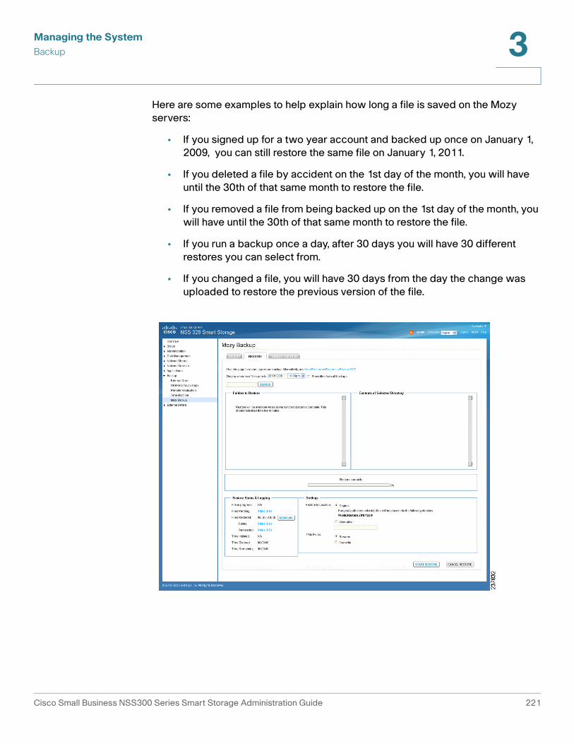
Managing the System
Backup 3
Here are some examples to help explain how long a file is saved on the Mozy
servers:
• If you signed up for a two year account and backed up once on January 1,
2009, you can still restore the same file on January 1, 2011.
• If you deleted a file by accident on the 1st day of the month, you will have
until the 30th of that same month to restore the file.
• If you removed a file from being backed up on the 1st day of the month, you
will have until the 30th of that same month to restore the file.
• If you run a backup once a day, after 30 days you will have 30 different
restores you can select from.
• If you changed a file, you will have 30 days from the day the change was
uploaded to restore the previous version of the file.
Cisco Small Business NSS300 Series Smart Storage Administration Guide 221

Managing the System
Backup 3
To restore a previous Mozy backup:
STEP 1 Choose Backup > Mozy Backup > Restore. The Restore window opens. From
this window, you can restore specific files.
Other restore options are also available from this window. Use these options when
the data being restored is a very large amount or if the NAS is unavailable for some
reason such as, damage to the NAS due to fire, flood, or hardware failure.
For an example of a large restore where these might be good options, take into
consideration that you can restore approximately 450 MB of data per hour on a
1 Mbps connection. If you are attempting to restore 250 GB on a 2 Mbps downlink,
you would be faced with 11.5 days of connection time to restore all that data. It is a
better option to have the restore DVDs sent to you using overnight mail.
• Web Restore—Click this link to go to Mozy.com and request copies of
backed up files directly from the Mozy website.
• Request a Restore DVD—Click this link to go to Mozy.com and request that
a DVD containing previously backed up files be sent to you.
NOTE There is a separate charge for the option of requesting a restore DVD.
STEP 2 The following options are available to search or select files to restore:
To search for previously backed up files:
a. In the Display versions of files prior to field, enter the date. From the drop-down
list, select a time. For the date entered, there must be a valid, existing backup.
• Show files from all backups—Check to display files from all backups
b. In the Search field, enter the filename you want to locate. The search is a
“string-match” based search and not a wildcard based search. For example, the
asterisk (*) is treated as a character in the string being searched. So, if you
enter text and an asterisk (*) in the Search field, nothing will be returned.
c. Click Search. The Search Result is displayed.
d. Select the files to restore.
Cisco Small Business NSS300 Series Smart Storage Administration Guide 222

Managing the System
Backup 3
Select the directories to restore:
a. In Folders to Restore, check the check box to select the directories, folders, or
files you want to restore. The folders expand and a check appears in the check
box for the folder and files that are selected for restore.
NOTE When you choose the file or folder you want to restore, the check has three
variations dependent on your selection. Black indicates a folder and all of the sub-
folders or files are selected. Gray indicates single folders or files within a directory
are selected. The gray check appears in the parent folder check box. Blank
indicates that no files are selected.
b. Click the arrow to expand the directory structure.
• Contents of Selected Directory—Dispays the files from the selected
directories.
STEP 3 In Restore Status, you can view the progress of the restore.
• File in progress—Displays the file currently being restored.
• Files Pending—Displays number of files and bytes remaining for restore.
Click the link, i.e. x files (x B), to display more information about the pending
files.
- Source—Directory path from where the file was originally backed up.
- Destination—Directory path to where the file is being restored.
- Time Initiated—Time the restore request was made.
- Status—Current status of the job in the restore queue, such as Pending,
Succeeded, or Failed.
• Files Restored—The first number indicates the number of files and bytes
queued to be restored. The second number indicates the number of files and
bytes that have been restored.
- View Log—Click the link to view the restore log history.
- Failed—Number of files and bytes that failed during the restore.
- Succeeded—Number of files and bytes that were restored successfully.
• Time Initiated—Time that the restore was started.
Cisco Small Business NSS300 Series Smart Storage Administration Guide 223

Managing the System
Backup 3
STEP 4 In Settings, configure the following restore parameters:
Restore to Location:
• Original—Select to restore the files to the original location. This is the
default. If original path does not exist, files will be placed into the following
directory:
/Public/Restore-19691231/
• Alternative—Select to restore the files to a specific folder. When this is
selected, the Select a folder dialog box opens and allows you to select the
folder to use on the NAS. After selecting the folder, click Finish.
If File Exists:
• Rename—Select to rename file if it currently exists.
• Overwrite—Select to overwrite existing files.
STEP 5 Click Start Restore. The Restore complete progress bar tracks the restore
progress and completion.
Managing Account Services
From the Manage Services window, you can view the account information
summary, manage notifications, manage the account, or deactivate the backup
service. If you are performing account management tasks, such as increasing
storage, changing payment details, or deactivating backup service, there is a link
provided that directs you to the Mozy website. For more information about Mozy
account management, see Mozy Account Pages, page 227.
Cisco Small Business NSS300 Series Smart Storage Administration Guide 224
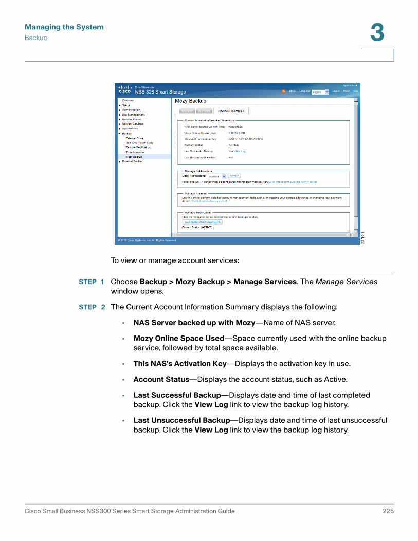
Managing the System
Backup 3
To view or manage account services:
STEP 1 Choose Backup > Mozy Backup > Manage Services. The Manage Services
window opens.
STEP 2 The Current Account Information Summary displays the following:
• NAS Server backed up with Mozy—Name of NAS server.
• Mozy Online Space Used—Space currently used with the online backup
service, followed by total space available.
• This NAS’s Activation Key—Displays the activation key in use.
• Account Status—Displays the account status, such as Active.
• Last Successful Backup—Displays date and time of last completed
backup. Click the View Log link to view the backup log history.
• Last Unsuccessful Backup—Displays date and time of last unsuccessful
backup. Click the View Log link to view the backup log history.
Cisco Small Business NSS300 Series Smart Storage Administration Guide 225

Managing the System
Backup 3
STEP 3 From Manage Notifications, you can set the Mozy Notifications to Disabled or
Enabled. The default setting is Disabled.
When Mozy Notifications is enabled, the following apply:
• Notification will be sent out at midnight everyday.
• Warning level only shows the number of successful backups.
• Error level shows the number of successful and failed backups with the error
log.
The NAS system error alert mechanism is configured from the Administration >
Notification > Alert Notification window. Alerts from Mozy will be sent to the email
address specified. See Alert Notification, page 77.
STEP 4 From Manage Account, you can perform detailed account management tasks,
such as increasing your storage allowance or changing your payment details. Click
the Mozy Account Management link. For more information about Mozy account
management, see Mozy Account Pages, page 227.
STEP 5 From Manage Mozy Client, you can stop or start the online backups to Mozy. This
would typically be used to troubleshoot issues with the Mozy online backup on
Cisco Smart Storage. You can also deactivate and activate the Mozy service.
To suspend or resume backups:
• To stop backups, click Suspend Mozy Backups. The Current Status field
will display status as Suspended and the message “Your files are currently
not being backed up to Mozy” is displayed.
• To restart backups, click Resume Mozy Backups. The Current Status field
will display status as Active.
To deactivate the Mozy service:
NOTE When you deactivate the Mozy backup service, the activation information from the
sys.cfg is cleared. It is important to have the email, activation key, and password
that you used to activate the service available before performing this step. Also,
when deactivating the Mozy backup service, the local database files will be
deleted. The local database files will be resynced from the Mozy server when the
Mozy backup service is activated.
a. Click Suspend Mozy Backups. The Current Status field will display status as
Suspended and the message “Your files are currently not being backed up to
Mozy” is displayed.
b. Click Deactivate Mozy Service. The Mozy service is deactivated.
Cisco Small Business NSS300 Series Smart Storage Administration Guide 226

Managing the System
Backup 3
To reactivate the Mozy service:
a. Choose Backup > Mozy Backup, then click Activate Mozy Service.
b. From the Mozy setup wizard Welcome window, select one of the following
options:
- Select I already have an activation key and password to re-enter the
previously used email, activation key, and password information.
OR
- Select I have an activation key but no password to enter a new
activation key and information.
c. Choose Backup > Mozy Backup > Manage Services. From the Manage
Services window, click Resume Mozy Backups. The Current Status field will
display status as Active.
NOTE You must click Resume Mozy Backups to complete the activation process and
resume the backup service.
Support for Mozy Issues with Cisco Smart Storage
For any Mozy issues with Cisco Smart Storage, if your product is under warranty
or you have a Cisco service contract, contact Cisco support first. If it is a Mozy
issue, you will be redirected by Cisco support to the Mozy support center. See
Appendix B, “Where to Go From Here.”
Mozy Support by Country
For more information regarding Mozy currency, language support, and support by
country, see:
http://cisco.mozy.com/country_support
Mozy Account Pages
From the Mozy website, you can manage your account and make changes, such
as increasing your storage allowance and changing your payment details.
Cisco Small Business NSS300 Series Smart Storage Administration Guide 227

Managing the System
Backup 3
To access the Mozy Account Pages:
STEP 1 From your web browser, access or type the following URL:
http://cisco.mozy.com
Or:
From your NAS device, choose Backup > Mozy Backup > Manage Services.
Then click the Mozy Account Management link.
STEP 2 From the Mozy website, click Log In in the upper-right corner of the window to
access the Account Pages. You will need to enter your Mozy account email and
password.
The following options are available from the Mozy Account Pages:
• My Account —View currently assigned licenses, reassign a license to an
email address, or upgrade your storage plan. You can also restore your files
from a specific storage device directly from the Mozy website.
• Account Information—View or edit the account information, change the
email address, or change the account password.
• Billing and Payment—View the payment information, plan, or billing history.
You can also change the credit card information.
• Purchase Activation Keys—Add Mozy online backup to another Smart
Storage device. You can select the number of licenses needed and the
storage amount. You also have the option to edit the default settings for your
license term and storage amount.
• FAQ—Menu of frequently asked questions with answers and applicable
steps provided.
• Contact Support—Lists the Mozy support email and phone contact.
STEP 3 To sign out of the Mozy Account Pages, click Log Out in the upper-right corner of
the window.
Cisco Small Business NSS300 Series Smart Storage Administration Guide 228

Managing the System
External Device 3
External Device
This section describes the external devices supported by NAS and includes the
following topics:
• External Storage Device
• UPS Settings
External Storage Device
The NAS is designed with external ports to support eSATA drives, USB drives, and
thumb drives for extended storage. From the External Device > External Storage
Device window, you can perform numerous functions on these external devices
such as formatting the device, removing the disk partition, and removing the
device from the NAS.
NOTE External devices are accessible to everyone who has network access to the NAS.
Therefore, all users on the NAS can read and write data to these devices.
!CAUTION Do not unplug an external device when it is in use to protect it and the data on it.
!CAUTION Formatting or removing a disk partition from an external device will delete all data
from the external device.
Cisco Small Business NSS300 Series Smart Storage Administration Guide 229

Managing the System
External Device 3
To format an external device:
STEP 1 Connect an external device to the NAS.
STEP 2 Choose External Device > External Storage Device from the Navigation menu.
The External Storage Device window opens.
STEP 3 Select the external storage device from the window.
STEP 4 Choose a format type.
STEP 5 Click Format Now. The external device is formatted in the selected format.
NOTE The NAS can format the external drive for a FAT32, NTFS, EXT3, EXT4, or HFS+ (Mac
only) file system. If you are formating your external drive for EXT3 or EXT4, it cannot
be recognized if you are using a Windows operating system. The NAS will
recognize each partition existing on the external drive is one disk. If a single drive
with multiple partitions is connecting to the NAS port, it will appeared as multiple
USB disks. For example, if you are using an external disk drive with four partitions,
the NAS will recognize each partition as USBdisk1, USBdisk2, USBdisk3, and
USBdisk4. To format a complete clean for external drives, you need to format each
partition.
Cisco Small Business NSS300 Series Smart Storage Administration Guide 230

Managing the System
External Device 3
To remove a partition from an external device:
STEP 1 Connect an external device to the NAS.
STEP 2 Choose External Device > External Storage Device from the Navigation menu.
The External Storage Device window opens.
STEP 3 Select the external storage device from the window.
STEP 4 Click Remove Disk Partition. The disk partition is removed from the selected
external device.
To remove an external device from the NAS:
STEP 1 Choose External Device > External Storage Device from the Navigation menu.
The External Storage Device window opens.
STEP 2 Select the external storage device from the window.
STEP 3 Click Remove Device. The selected external device is removed from the NAS.
UPS Settings
The NAS supports connection to an Uninterruptible Power Supply (UPS) to protect
your system from abnormal system shutdown caused by a power outage. From
the External Device > UPS Settings window, you can enable UPS support and
configure the UPS settings, model and IP address.
The UPS Information area shows the UPS brand, model, AC power status, battery
capacity, and estimated protection time for your UPS. If these fields are not filled,
either the UPS is not communicating with the NAS or it does not provide this
information to the NAS.
Cisco Small Business NSS300 Series Smart Storage Administration Guide 231

Managing the System
External Device 3
To enable UPS support:
STEP 1 Ensure that the UPS is connected to your NAS according to the instructions from
the UPS manufacturer.
STEP 2 Choose External Device > UPS Settings from the Navigation menu. The UPS
Settings window opens.
STEP 3 Click Enable UPS Support.
STEP 4 To turn off the NAS after a specified amount of time after power has failed, click
After the AC power fails for x minute(s), turn off the server, and specify a time in
minutes.
STEP 5 To put the server in standby mode after the power has failed, click After the AC
power fails for x minute(s), the server should enter standby mode, and specify
a time in minutes. When power resumes, the system resumes to operation status.
STEP 6 In Protocol, choose a connection method from the drop-down list:
• USB UPS (auto detect)— Choose if your UPS is connected to the NAS via
USB.
• APC UPS with SNMP Management—Choose if your UPS is connected to
the NAS via IP SNMP.
Cisco Small Business NSS300 Series Smart Storage Administration Guide 232

Managing the System
External Device 3
STEP 7 Enter the IP address of the UPS in the address fields.
STEP 8 Click Apply. Your UPS settings are updated to the NAS.
Cisco Small Business NSS300 Series Smart Storage Administration Guide 233

4
Configuring the NAS for Active Directory Authentication
The NAS supports Microsoft Active Directory Domain Services (AD DS). This
chapter describes how to configure your NAS to join Microsoft Active Directory
Services.
NOTE The NAS supports Windows Server 2000 and above.
Before You Begin
Before you configure NAS for Active Directory authentication, ensure the following:
• You have access to an Active Directory domain.
• You have access to a properly configured DNS server.
• You have the following information:
- An Active Directory domain administrator account for authentication.
- The fully Qualified Domain Name (FQDN) of the Active Directory domain.
- The NetBIOS domain name for the Active Directory domain.
- The hostname or IP address (hostname is preferred) of the domain
controller running the Active Directory domain.
The domain controller is a Windows Server 2000 or above computer
running Active Directory Services.
- (Optional) The name of the Organizational Unit (OU) the NAS belongs to.
• The IP address of your NAS.
NOTE It is important to note the time and date settings of your NAS device. A time
deviation of more than 5 minutes between the NAS and your Domain Controller
causes Kerberos Authentication to fail and you cannot join your domain.
Cisco Small Business NSS300 Series Smart Storage Administration Guide 234

Configuring the NAS for Active Directory Authentication
Joining the NAS to Your Domain 4
NOTE We recommend that you configure your NAS to use your Domain Controller for time
synchronization.
Joining the NAS to Your Domain
This section describes how to join your NAS to your domain.
• Configuring Date and Time, page 235
• Configuring DNS Settings, page 236
• Configuring Microsoft Networking, page 237
Configuring Date and Time
To configure NAS to use an NTP server:
STEP 1 Start the web-based configuration utility of your NAS device.
To start the web-based configuration utility, open a web browser and enter the
following in the URL field:
http://<IP Address>:8080
Where <IP Address> is the IP address of your NAS device.
STEP 2 Choose Administration > General Settings > Date and Time.
STEP 3 To get the date and time from an NTP server, check Synchronize with an internet
time server automatically.
STEP 4 To specify an NTP server in the Server field, check Input Manually.
Cisco Small Business NSS300 Series Smart Storage Administration Guide 235

Configuring the NAS for Active Directory Authentication
Joining the NAS to Your Domain 4
STEP 5 In the Server field, enter the hostname or IP address of the NTP server.
Make sure the time difference between the NAS and the domain controller is less
than five minutes. If time difference is greater than five minutes, Kerberos
Authentication fails and you cannot join the domain. To avoid this possibility, we
recommend you use the domain controller as the NTP server.
STEP 6 To save your settings, click Apply.
Configuring DNS Settings
To configure DNS settings for your NAS, follow these steps.
STEP 1 From the web-based configuration utility of your NAS, click Administration >
Network > TCP/ IP.
STEP 2 In the Primary DNS Server field, enter the IP address of the primary DNS server.
We recommend that you use the domain controller as the primary DNS server.
STEP 3 In the Secondary DNS Server field, enter the IP address of the secondary DNS
server.
STEP 4 To save your settings, click Apply.
Cisco Small Business NSS300 Series Smart Storage Administration Guide 236

Configuring the NAS for Active Directory Authentication
Joining the NAS to Your Domain 4
Configuring Microsoft Networking
To configure your NAS to be an Active Directory domain member, follow these
steps.
STEP 1 From the web-based configuration utility of your NAS device,
choose Network Services > Microsoft Networking.
STEP 2 Click the AD Domain Member radio button.
STEP 3 (Optional) In the Server Description field, enter a description of your NAS.
Cisco Small Business NSS300 Series Smart Storage Administration Guide 237

Configuring the NAS for Active Directory Authentication
Joining the NAS to Your Domain 4
STEP 4 In the Domain NetBIOS Name field, enter the name of your NetBIOS domain.
You can find the name of your NetBIOS domain from a domain computer or a
domain controller.
To find the name of the NetBIOS domain for your organization from a domain
computer, follow these steps:
a. Choose Start > Run.
b. In the Open field, enter CMD and click OK.
c. At the command prompt, enter the following:
nbtstat -A <IP_address_of_domain_controller>
The output of the command should be similar to the following:
C:\Users\a_user>nbtstat -A 192.168.52.250
Local Area Connection 2:
Local Area Connection:
Node IpAddress: [192.168.52.39] Scope Id: []
NetBIOS Remote Machine Name Table
Name Type Status
---------------------------------------------
MY_DC <00> UNIQUE Registered
NSS <00> GROUP Registered
NSS <1C> GROUP Registered
MY_DC <20> UNIQUE Registered
NSS <1B> UNIQUE Registered
MAC Address = 00-0C-29-E2-ED-5E
In the NetBIOS Remote Machine Name Table, the first row contains the
hostname of the domain controller (in this example, MY_DC) and the second row
contains the NetBIOS name (in this example, NSS), as indicated by the text in
bold.
Cisco Small Business NSS300 Series Smart Storage Administration Guide 238

Configuring the NAS for Active Directory Authentication
Joining the NAS to Your Domain 4
To find the name of the NetBIOS domain for your organization from a domain
controller, follow these steps:
a. Open “Active Directory Users and Computers” Snap-In.
b. Right-click on you fully qualified domain name and choose Properties.
In the Properties window, the Domain Name (Pre-Windows 2000) field displays
the NetBIOS name.
STEP 5 In the AD Server Name field, enter the hostname of your domain controller.
To find the hostname of your domain controller:
a. Log in to your domain controller.
b. Click Start, right-click My Computer, and choose Properties.
c. In the Properties window, click Computer Name.
In the Properties window, the Full computer name field displays the hostname.
For example, if the full computer name is mydc.example.com, the hostname of
the domain controller is mydc.
You can also follow these steps to find the hostname of your domain controller:
a. Choose Start > Run, enter CMD in the Run window, and click OK.
b. In the command window, type Hostname and press Enter.
The returned text is the hostname of your domain controller.
STEP 6 In the Domain field, enter the fully qualified domain name (for example,
mycompany.local).
STEP 7 (Optional) In the Organizational Unit (OU) field, enter the path of the OU
containment.
STEP 8 In the Domain Administrator Username field, enter the username of the domain
controller administrator.
STEP 9 In the Domain Administrator Password field, enter the password of the domain
controller administrator.
Cisco Small Business NSS300 Series Smart Storage Administration Guide 239

Configuring the NAS for Active Directory Authentication
Joining the NAS to Your Domain 4
STEP 10 To save your settings, click Apply.
A window appears displaying a message indicating whether your NAS has
successfully joined the domain controller. In addition, the web-based utility adds
an entry to the system log.
If your NAS failed to join the domain controller, check your settings and try again.
STEP 11 Confirm that your NAS successfully joined the domain controller.
a. Choose Administration > Users.
b. From the drop-down menu, choose Domain Users.
c. Verify that you see the list of all the Active Directory domain users.
d. Choose Administration > User Groups.
e. From the drop-down menu, choose Domain Groups.
f. Verify that you see the list of all the Active Directory domain user groups.
If your NAS successfully joined the Active Directory domain, you can access the
NSS shared folders from any computer in the domain.
To open a shared folder, open a Windows Explorer window and enter the following
in the Address field:
\\<NSS_Name>\<Shared_Folder_Name>
To access NAS shared folders from a computer which is not part of the Active
Directory domain, use a Windows Explorer window to open the shared folder and
then provide your credentials as follows:
<NetBios_Domain_Name>\<domain_username>
For example, mydomain\nssuser1.
Cisco Small Business NSS300 Series Smart Storage Administration Guide 240

5
NAS Maintenance
This chapter describes how to restart or shut down the NAS, reset the NAS
system hardware, the steps to take to replace a hard disk, what to do in the event
of a power outage, and how your system temperature is protected. The following
sections are included:
• Restart or Shut Down the NAS
• Hardware System Reset
• Disk Failure or Malfunction
• Power Outage or Abnormal Shutdown
• System Software Abnormal Operation
• System Temperature Protection
Cisco Small Business NSS300 Series Smart Storage Administration Guide 241

NAS Maintenance
Restart or Shut Down the NAS 5
Restart or Shut Down the NAS
Follow the steps below to restart or shut down the NAS.
STEP 1 Choose Administration > Power Management from the Navigation menu. The
Power Management window opens.
STEP 2 To restart the NAS immediately, click RESTART. To shutdown the NAS immediately,
click SHUTDOWN.
You can also press the power button for 5 seconds to turn off the NAS. The NAS
beeps once and shuts down immediately.
Hardware System Reset
There are two ways to reset the NAS system hardware: basic and advanced.
NOTE Hardware system reset as described in this chapter is different from the
Administration > Restore to Factory Default command. See Restore to Factory
Default, page 93 more details regarding the Restore to Factory Default
command.
Cisco Small Business NSS300 Series Smart Storage Administration Guide 242

NAS Maintenance
Hardware System Reset 5
!CAUTION To prevent the unintentional loss of NAS system settings, be sure to read and
understand the basic and advanced descriptions of the hardware system reset
function before performing a system hardware reset.
NOTE To reset the system by the reset button, the option Enable configuration reset
switch in Administration > Hardware must be activated.
Cisco Small Business NSS300 Series Smart Storage Administration Guide 243

NAS Maintenance
Hardware System Reset 5
Basic System Reset (3 seconds)
The following settings are reset to their default value during a basic system reset:
To perform a basic system reset:
STEP 1 Press and hold the reset button for 3 seconds, a beep will sound.
STEP 2 Wait for the NAS to reboot.
System Basic System Reset
(1 beep)
Advanced System Reset
(2 beeps)
All NAS models Press the reset button for
3 seconds.
Press the reset button for
10 seconds.
Feature/Function Setting after 3 Second
Reset
System administration password admin
Administration > Network > TCP/ IP Obtain IP address settings
automatically via DHCP
Administration > Network >TCP/ IP Disable Jumbo Frame
General Settings > System Administration >
System Port
8080 (system service port)
Administration > Security > Security Level Low (Allow all connections)
LCD panel password (only applicable to
models with LCD panel)
No Password
Cisco Small Business NSS300 Series Smart Storage Administration Guide 244

NAS Maintenance
Disk Failure or Malfunction 5
Advanced System Reset (10 seconds)
!CAUTION Users, User Groups, and Network Share folders will be cleared during an advanced
system reset.
During an advanced system reset, the NAS will reset all system settings to their
default values just as it does by web-based system reset in Administration >
Restore to Factory Default except that all data remains on the disk. However, to
retrieve the data after an advanced system reset, you will need to create the same
network share folders on the NAS to access the data. Use the “specify path” when
creating the network share folders, in order to access the data.
To perform an advanced system reset:
STEP 1 Press and hold the reset button for 10 seconds, you will hear two beeps at the
third and the tenth seconds.
STEP 2 Wait for the NAS to reboot.
STEP 3 Adjust NAS system settings as necessary.
Disk Failure or Malfunction
If one of your disks fail, the status indicator on the NAS will blink red; you can verify
that a disk failure has occurred by viewing the system logs.
NOTE When configuring your NAS using RAID, be sure to select the proper RAID level for
adequate data protection. Refer to Disk Management, page 105 for more details
on RAID.
Perform the following steps to replace a failed disk.
STEP 1 Choose Administration > System Log Settings from the Navigation menu. The
System Logs window opens.
STEP 2 If a disk failure has occurred, the log will specify which disk has failed.
STEP 3 Locate the failed disk on the NAS and remove it. The failed disk can be identified
by a red indicator over the failed disk.
Cisco Small Business NSS300 Series Smart Storage Administration Guide 245

NAS Maintenance
Disk Failure or Malfunction 5
!CAUTION Be especially careful to pull out the disk from the correct drive slot. An improperly
removed disk in a RAID array can cause catastrophic failure to the remaining
degraded RAID array, including total data loss.
STEP 4 Remove the failed drive from the drive sled by removing the screws that attach it.
STEP 5 Connect a new disk into the drive sled using the appropriate screws for the disk.
STEP 6 Insert the drive assembly into the NAS.
STEP 7 If you are using a mirroring RAID disk configuration, the NAS will configure the
drive and place it into the RAID array. This operation may take several minutes or
hours depending on the size of the disk and RAID array.
STEP 8 If you are using a non-RAID disk configuration, you may need to reformat and
reconfigure the new disk. You can change disk configuration from
Disk Management > Volume management.
NOTE You can view the System Logs to verify that the NAS has returned to normal
operation.
If you experience any other malfunction or failure with the NAS, do the following:
STEP 1 Record the malfunction status or error messages shown in system logs.
STEP 2 Stop using the failed NAS and turn it off.
STEP 3 Contact customer service for technical support.
NOTE The NAS must be repaired by professional technicians, do not try to repair the
server yourself. Back up any important files or folders to avoid potential data loss
due to disk failure.
Cisco Small Business NSS300 Series Smart Storage Administration Guide 246

NAS Maintenance
Power Outage or Abnormal Shutdown 5
Power Outage or Abnormal Shutdown
In case of a power outage or improper shutdown of the NAS, it will resume to the
state before it is shut down.
NOTE Other power outage options are available from the External Device >
UPS Settings window.
If your NAS does not function properly after restart, do the following:
STEP 1 If the system configuration is lost, configure the system again.
STEP 2 In the event of abnormal operation of the NAS, contact customer service for
technical support.
System Software Abnormal Operation
If the system software does not operate properly, the NAS automatically restarts
to resume normal operation. If you find that the system restarts continuously, it may
fail to resume normal operation. In this case, contact technical support.
System Temperature Protection
The system shuts down automatically for hardware protection if any of the
following criteria is met:
• The system temperature exceeds 70°C (158°F)
• The CPU temperature exceeds 85°C (185°F)
• The hard drive temperature exceeds 65°C (149°F)
Cisco Small Business NSS300 Series Smart Storage Administration Guide 247

NAS Maintenance
Product Battery Replacement 5
Product Battery Replacement
This product contains a permanently affixed battery, so for product safety and
data integrity reasons such battery should only be removed or replaced
professionally by a repair technician or waste management professional. Please
contact Cisco or an authorized service agent if the product fails to perform due to
malfunction of the permanently affixed battery.
!CAUTION There is the danger of explosion if the battery is replaced incorrectly.
Cisco Small Business NSS300 Series Smart Storage Administration Guide 248

6
Troubleshooting Abnormal RAID Operation
This chapter describes steps to troubleshoot abnormal RAID operation of your
Cisco NAS.
NOTE If the NAS administration interface cannot be accessed due to an improperly
configured port trunking mode, improperly configured Jumbo Frame setting, or an
incompatible switch, reset the network settings by pressing the reset button on the
back panel of the NAS for 3 seconds.
Before You Begin the Troubleshooting Process
!CAUTION Before troubleshooting the RAID configuration of your NAS, back up the important
data on the NAS to avoid any potential data loss.
!CAUTION Insert or remove only one drive from the NAS at a time.
!CAUTION After inserting or removing a hard drive, wait until you hear two beeps from the NAS
before inserting or removing the next hard drive.
Cisco Small Business NSS300 Series Smart Storage Administration Guide 249
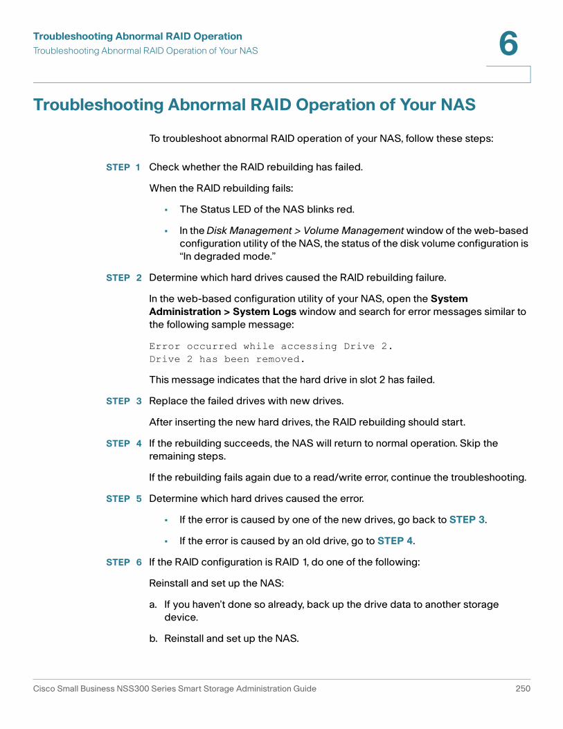
Troubleshooting Abnormal RAID Operation
Troubleshooting Abnormal RAID Operation of Your NAS 6
Troubleshooting Abnormal RAID Operation of Your NAS
To troubleshoot abnormal RAID operation of your NAS, follow these steps:
STEP 1 Check whether the RAID rebuilding has failed.
When the RAID rebuilding fails:
• The Status LED of the NAS blinks red.
• In the Disk Management > Volume Management window of the web-based
configuration utility of the NAS, the status of the disk volume configuration is
“In degraded mode.”
STEP 2 Determine which hard drives caused the RAID rebuilding failure.
In the web-based configuration utility of your NAS, open the System
Administration > System Logs window and search for error messages similar to
the following sample message:
Error occurred while accessing Drive 2.Drive 2 has been removed.
This message indicates that the hard drive in slot 2 has failed.
STEP 3 Replace the failed drives with new drives.
After inserting the new hard drives, the RAID rebuilding should start.
STEP 4 If the rebuilding succeeds, the NAS will return to normal operation. Skip the
remaining steps.
If the rebuilding fails again due to a read/write error, continue the troubleshooting.
STEP 5 Determine which hard drives caused the error.
• If the error is caused by one of the new drives, go back to STEP 3.
• If the error is caused by an old drive, go to STEP 4.
STEP 6 If the RAID configuration is RAID 1, do one of the following:
Reinstall and set up the NAS:
a. If you haven’t done so already, back up the drive data to another storage
device.
b. Reinstall and set up the NAS.
Cisco Small Business NSS300 Series Smart Storage Administration Guide 250

Troubleshooting Abnormal RAID Operation
Troubleshooting Abnormal RAID Operation of Your NAS 6
Execute RAID 1 migration:
a. Format one of the new drives as a single drive.
b. Back up the data on the NAS to the new drive using Web File Manager.
c. Unplug the drive with errors and insert a new drive in its place.
d. Execute a RAID 1 migration.
STEP 7 If the RAID configuration is RAID 5 or 6, back up the data and run system
installation and configuration again.
Cisco Small Business NSS300 Series Smart Storage Administration Guide 251

7
Using the LCD Display
This chapter describes the LCD display on the front panel of the NSS324 and
NSS326 Smart Storage devices. Using the LCD display, you can configure the
disks and view the system information. The following sections are included:
• System Configuration Using the LCD Display
• Viewing System Information Using the LCD Display
• System Messages
System Configuration Using the LCD Display
When the NAS is configured and the device is powering up, you can view the NAS
name and IP address. For example:
For the initial or first-time installation, the LCD display shows the number of hard
drives detected and the IP address.
N A S B E 4 5 E 21 2 7 . 2 1 0 . 1 3 9 . 1 5 2
Number of Disks
Detected
Default Disk
Configuration
Available Disk Configuration Options
1 Single Single
2 RAID 1 Single, JBOD, RAID 0, RAID 1
3 RAID 5 Single, JBOD, RAID 0, RAID 5
4 or more RAID 5 Single, JBOD, RAID 0, RAID 5, RAID 6
Cisco Small Business NSS300 Series Smart Storage Administration Guide 252

Using the LCD Display
System Configuration Using the LCD Display 7
Use the Select and Enter button when configuring the disks using the LCD display.
The following shows the location of the Select and Enter button on the NSS326.
The location is the same on the front panel of the NSS324.
To configure the disks using the LCD display:
STEP 1 At the prompt Config Disks? in the LCD display, press Select to choose the disk
configuration.
For example, when you power on the NAS with five disks installed, the LCD display
shows:
Number Item Description
1 Enter Displays options for configuration or status such as bootup progress, disk configuration, and volume. After configuration, you can view the hostname and IP address.
2 Select Press Select to confirm a configuration or menu option.
ENTER
SELECT
1979
75
STATUS LAN USB eSATA
NSS 326
Smart Storage
1 2
C o n f i g . D i s k s ?R A I D 5
Cisco Small Business NSS300 Series Smart Storage Administration Guide 253

Using the LCD Display
System Configuration Using the LCD Display 7
The following options are available:
• Single Disk—Uses the disk drives as single disk volumes. When a drive
failure occurs, all data is lost.
• JBOD (Linear)—JBOD lets you combine multiple disks of mixed capacities
into a single logical storage device. The capacity of the JBOD array is the
sum of the total capacities of the individual component disks (that is, it does
not have the limitation of RAID 1 where you lose some capacity when using
mixed sized disks). JBOD offers no performance increase compared to the
component disks. It has lower reliability than the component disks, as the
failure of a single disk results in the failure of the whole array.
• RAID 0—Distributes data across several disks in a way which that improves
speed and full capacity. All data on all disks will be lost if any single disk fails.
• RAID 1—Uses two disks (mirrored disks) which each store the same data, so
that data is not lost as long as one disk survives. Total capacity of the array
equals the capacity of the smaller disk.
• RAID 5—Combines three or more disks in a way that protects data against
loss of any single disk.
• RAID 6—Combines four or more disks in a way that protects data against
loss of any two disks.
STEP 2 After choosing the disk configuration, press Enter. The LCD display shows the
configuration that you selected. For example:
Yes is the default disk configuration.
When you select RAID 1, RAID 5, or RAID 6 configuration, the system initializes the
disks, creates the RAID device, formats the RAID device, and mounts it as a volume
on the NAS. The progress is shown on the LCD display. When the progress
reaches 100 percent, you can access the RAID volume, create share folders, and
upload files to the folders on the NAS. In the interim, to ensure that the stripes and
blocks in all the RAID component devices are ready, the NAS will execute RAID
synchronization. The synchronization progress can be monitored from the Disk
Management > Volume Management window. The synchronization rate is
approximately 30-60 MB/s. This number can vary by disk models, system
resource usage, and other factors.
C h o o s e R A I D 5 ?Y e s N o
Cisco Small Business NSS300 Series Smart Storage Administration Guide 254

Using the LCD Display
System Configuration Using the LCD Display 7
NOTE If any disk of the RAID array fails during the synchronization, the RAID device will
enter degraded mode. The volume data is still accessible. If you replace a failed
disk with a new disk to the RAID device, it will start to rebuild. You can check the
status from the Disk Management > Volume Management window.
STEP 3 Press Enter to continue. The LCD display shows:
No is the default. If you choose yes, the disk volume is encrypted with a password
and provides an extra layer of security against the theft of data. The default
encryption password is a password of the “admin” account.
NOTE To change the encryption password, choose Disk Management > Encrypted File
System from the Navigation menu. See Encrypted File System, page 117.
STEP 4 Press Enter to continue. The system configuration progress is displayed. When the
configuration is complete, you will receive an IP address and default NAS device
name that is shown in the LCD display.
STEP 5 Start a web browser. You can access the management GUI from a web browser
using either the NAS IP address or NAS device name.
• In the Address bar, enter the IP address of the device that is shown in the LCD
display:
http://<NAS IP address>:8080
Or
• In the Address bar, enter the NAS device name that is shown in the LCD
display:
http://<NAS device name>:8080
STEP 6 When the login window opens, enter the administrator account username and
password.
The default username is admin. The default password is admin.
Username and password are case sensitive.
STEP 7 Click Login.
STEP 8 Follow the prompts to change the admin password.
STEP 9 Click Submit.
E n c r y p t V o l u m e ?Y e s N o
Cisco Small Business NSS300 Series Smart Storage Administration Guide 255

Using the LCD Display
Viewing System Information Using the LCD Display 7
STEP 10 When the login window opens, enter the administrator account username admin
and the new administrator password that you created in STEP 8.
Viewing System Information Using the LCD Display
When the LCD display shows the NAS name and IP address, press the Enter
button for two seconds to enter the Main Menu. Press the Select button to move
forward through the options.
From the Main Menu you can view system information, shut down or reboot the
NAS, or modify the password for the LCD display.
The Main Menu displays the following items:
• TCP/ IP
• Physical Disk
• Volume
• System
• Shut Down
• Reboot
• Password
• Back
TCP/ IP
From the TCP/IP menu, press the Select button to move forward through the
options. In TCP/ IP, you can view the following options:
• LAN IP Address—IP address of this interface.
• LAN Subnet Mask—Subnet mask of this interface.
• LAN Gateway—IP address of the network gateway device.
• LAN PRI. DNS—IP address of the Domain Name System (DNS) server. This
address is typically provided by your Internet Service Provider (ISP).
Cisco Small Business NSS300 Series Smart Storage Administration Guide 256

Using the LCD Display
Viewing System Information Using the LCD Display 7
• LAN SEC. DNS—Second DNS server.
In Network Settings, press the Enter button to enter the Network Settings. Press
the Select button to move forward through the options.
• Network Settings:
- Network Settings – DHCP—Specifies whether this interface uses
Dynamic Host Configuration Protocol (DHCP).
- Network Settings – Static IP—If a static IP address is configured,
shows static IP address, subnet mask, gateway, and DNS of LAN 1 and
LAN 2.
- Network Settings – BACK—Move back in the menu options.
• Back to Main Menu—Return to the Main Menu.
Physical Disk
In Physical disk, you can view the following options:
• Disk Info
• Back to Main Menu
To view the physical disk:
STEP 1 From the Main Menu, press the Select button until the Physical disk option is
displayed.
STEP 2 Press the Enter button. The Disk Info shows the temperature and the capacity of
the first disk.
STEP 3 Press the Select button to view each disk.
STEP 4 When Back to Main Menu is displayed, press the Enter button to return to the Main
Menu.
D i s k : 1 T e m p : 5 0 ° CS i z e : 2 3 2 G B
Cisco Small Business NSS300 Series Smart Storage Administration Guide 257

Using the LCD Display
Viewing System Information Using the LCD Display 7
Volume
The Volume option shows the disk configuration of the NAS.
To view the volume:
STEP 1 From the Main Menu, press the Select button until the Volume option is displayed.
STEP 2 Press the Enter button. The first line shows the RAID configuration and storage
capacity. The second line shows the member drive number of the configuration.
STEP 3 If there is more than one volume, press the Select button to view the information.
STEP 4 When Back to Main Menu is displayed, press the Enter button to return to the Main
Menu.
The following table shows the description of the LCD messages for RAID 5
configuration.
R A I D 5 7 5 0 G BD r i v e 1 2 3 4
LCD Display Drive Configuration
RAID 5+S RAID 5 + spare
RAID 5 (D) RAID 5 degraded mode
RAID 5 (B) RAID 5 rebuilding
RAID 5 (S) RAID 5 re-synchronizing
RAID 5 (U) RAID 5 is unmounted
RAID 5 (X) RAID 5 non-activated
Cisco Small Business NSS300 Series Smart Storage Administration Guide 258

Using the LCD Display
Viewing System Information Using the LCD Display 7
System
The System option shows the system temperature and the rotation speed of the
system fan.
To view the system option:
STEP 1 From the Main Menu, press the Select button until the System option is displayed.
STEP 2 Press the Enter button. The CPU and system temperatures are displayed.
STEP 3 Press the Select button to view the rotation speed of the system fan. The NSS326
displays FAN1 and FAN2.
STEP 4 Press the Select button. When Back to Main Menu is displayed, press the Enter
button to return to the Main Menu.
Shut Down
Use the Shut down option to power off the NAS.
To power off the NAS:
STEP 1 From the Main Menu, press the Select button until the Shut down option is
displayed.
STEP 2 Press the Select button to select Yes.
STEP 3 Press the Enter button to confirm.
C P U T e m p : 5 0 ° CS y s T e m p : 5 5 ° C
S y s F A N 1 : 8 6 5 R P MS y s F A N 2 : 8 6 5 R P M
Cisco Small Business NSS300 Series Smart Storage Administration Guide 259

Using the LCD Display
Viewing System Information Using the LCD Display 7
Reboot
Use the Reboot option to restart the NAS.
To reboot the NAS:
STEP 1 From the Main Menu, press the Select button until the Reboot option is displayed.
STEP 2 Press the Select button to select Yes.
STEP 3 Press the Enter button to confirm.
Password
The default password of the LCD display is blank. Enter the Password option to
change the password of the LCD display.
NOTE The LCD password is not the same as the “admin” account password.
To change the password of the LCD display:
STEP 1 From the Main Menu, press the Select button until the Password option is
displayed. The following is shown:
STEP 2 Select Yes to continue.
STEP 3 Enter a password with a maximum of eight numeric characters (0-9).
STEP 4 When the cursor moves to OK, press the Enter button. To confirm the changes,
verify the password.
C h a n g e P a s s w o r dY e s N o
N e w P a s s w o r d :O K
Cisco Small Business NSS300 Series Smart Storage Administration Guide 260

Using the LCD Display
System Messages 7
Back
Select the Back option to return to the main menu.
System Messages
When the NAS encounters system errors, an error message is shown on the LCD
display. Press the Enter button to view the message. Press the Enter button again
to view the next message.
S y s t e m E r r o r !P l s . C h e c k L o g s
System Message Description
Sys. Fan Failed System fan failed.
Sys. Overheat System is overheated.
HDD Overheat Disk overheated.
CPU Overheat CPU is overheated.
Network Lost Both LAN 1 and LAN 2 are
disconnected in Failover or
Load-Balancing mode.
LAN1 Lost LAN 1 is disconnected.
LAN2 Lost LAN 2 is disconnected.
HDD Failure Disk has failed.
HDD Ejected Disk is ejected.
Vol1 Full Volume is full.
Vol1 Degraded Volume is in degraded mode.
Vol1 Unmounted Volume is unmounted.
Vol1 Nonactivate Volume is not activated.
Cisco Small Business NSS300 Series Smart Storage Administration Guide 261

A
.
Specifications
This appendix lists the specifications for the Cisco Small Business NSS322,
NSS324, and NSS326 Smart Storage devices.
Feature NSS322 NSS324 NSS326
Physical Specifications
Form Desktop Desktop Desktop
Dimensions
(H x W x D)
5.91 x 4.02 x 8.5 in.
150 x 102 x 216 mm
6.97 x 7.09 x 9.25 in.
177 x 180 x 235 mm
6.89 x 10.12 x 9.25 in
175 x 257 x 235 mm
Net Weight 3.84 lbs
1.74 kg
8.04 lbs
3.65 kg
11.46 lbs
5.2 kg
Gross Weight 11.02 lbs
5 kg
18.43 lbs
8.36 kg
22.35 lbs
10.14 kg
Hardware Specifications
Network 2 Gigabit LAN ports 2 Gigabit LAN ports 2 Gigabit LAN ports
eSATA 2 (back) 2 (back) 2 (back)
Memory 1GB DDRII RAM 1GB DDRII RAM 1GB DDRII RAM
Flash 512 MB 512 MB 512 MB
USB 2.0 x 5 1 (front) 4 (back) 1 (front) 4 (back) 1 (front) 4 (back)
Power
Type External power
adaptor
Internal power
supply
Internal power
supply
Input 100-240V~,
47~63Hz, 7A
100-240V~,
47~63Hz, 3.5A
100-240V~,
47~63Hz, 3.5A
Cisco Small Business NSS300 Series Smart Storage Administration Guide 262
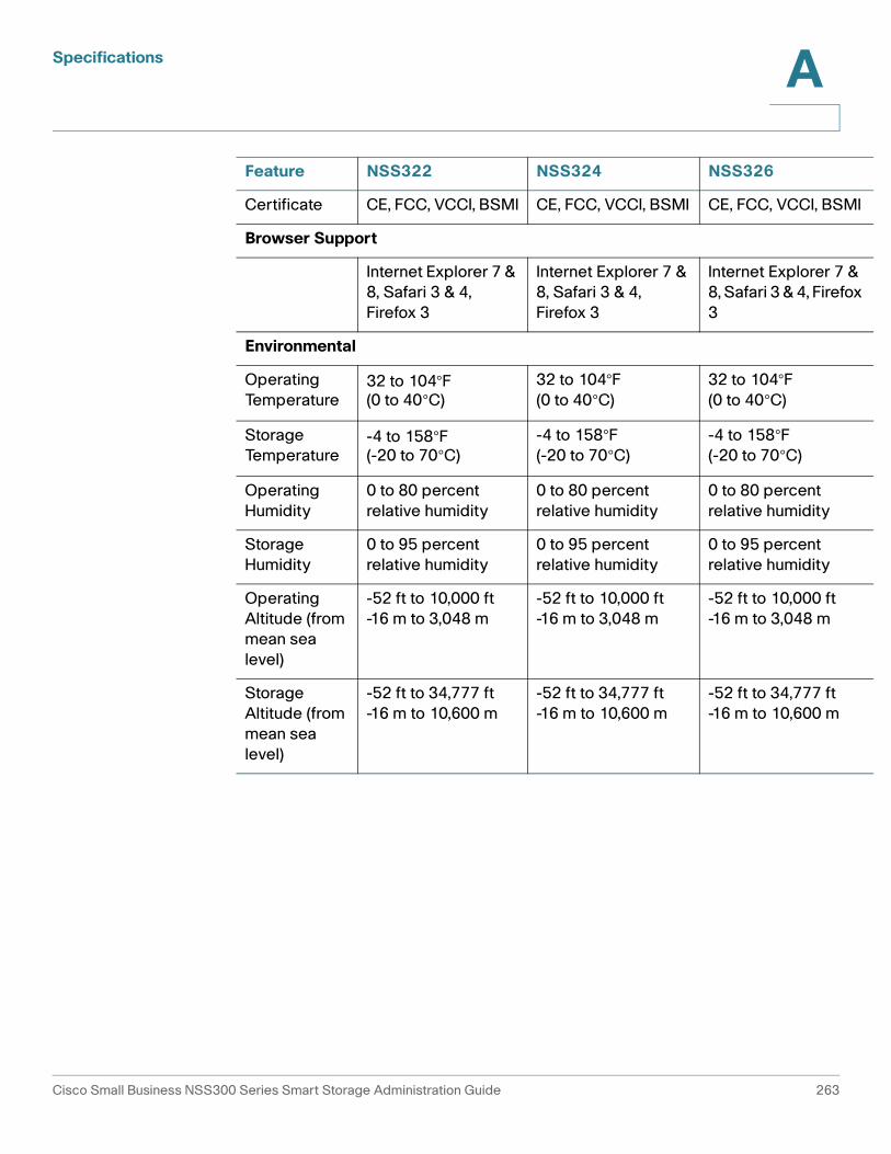
Specifications A
I
x
Certificate CE, FCC, VCCI, BSMI CE, FCC, VCCI, BSMI CE, FCC, VCCI, BSM
Browser Support
Internet Explorer 7 &
8, Safari 3 & 4,
Firefox 3
Internet Explorer 7 &
8, Safari 3 & 4,
Firefox 3
Internet Explorer 7 &
8, Safari 3 & 4, Firefo
3
Environmental
Operating
Temperature32 to 104°F (0 to 40°C)
32 to 104°F
(0 to 40°C)
32 to 104°F
(0 to 40°C)
Storage
Temperature-4 to 158°F (-20 to 70°C)
-4 to 158°F
(-20 to 70°C)
-4 to 158°F
(-20 to 70°C)
Operating
Humidity
0 to 80 percent
relative humidity
0 to 80 percent
relative humidity
0 to 80 percent
relative humidity
Storage
Humidity
0 to 95 percent
relative humidity
0 to 95 percent
relative humidity
0 to 95 percent
relative humidity
Operating
Altitude (from
mean sea
level)
-52 ft to 10,000 ft
-16 m to 3,048 m
-52 ft to 10,000 ft
-16 m to 3,048 m
-52 ft to 10,000 ft
-16 m to 3,048 m
Storage
Altitude (from
mean sea
level)
-52 ft to 34,777 ft
-16 m to 10,600 m
-52 ft to 34,777 ft
-16 m to 10,600 m
-52 ft to 34,777 ft
-16 m to 10,600 m
Feature NSS322 NSS324 NSS326
Cisco Small Business NSS300 Series Smart Storage Administration Guide 263

B
Where to Go From Here
Cisco provides a wide range of resources to help you obtain the full benefits of the
Cisco Small Business Smart Storage.
Support
Cisco Small Business Support Community
www.cisco.com/go/smallbizsupport
Online Technical Support and Documentation(Login Required)
www.cisco.com/support
Phone Support Contacts www.cisco.com/en/US/support/tsd_cisco_small_business _support_center_contacts.html
Software Downloads(Login Required)
Go to tools.cisco.com/support/downloads, and enter the model number in the Software Search box.
Mozy Support by Email [email protected]
Mozy Support by Phone 866-789-6699
Mozy currency, language support, and support by country
http://cisco.mozy.com/country_support
Product Documentation
NSS322, NSS324, and
NSS326 Smart Storage
(Datasheets, Firmware,
Quick Start Guides, FAQs,
Application Notes,
Release Notes, Approved
Vendor List, Regulatory
Compliance and Safety
Information)
www.cisco.com/go/smallbizsmartstorage
Add-on PKG Applications www.cisco.com/go/storage-apps
Cisco Small Business NSS300 Series Smart Storage Administration Guide 264

Where to Go From Here B
Cisco Small Business
Cisco Partner Central for Small Business(Partner Login Required)
www.cisco.com/web/partners/sell/smb
Cisco Small Business Home
www.cisco.com/smb
Marketplace www.cisco.com/go/marketplace
Cisco Small Business NSS300 Series Smart Storage Administration Guide 265