Embed Size (px)
Citation preview

NRGreen Power L.P.
Whitecourt Recovered Energy Project
Final Report for Climate Change Emissions Management Corporation
(CCEMC)
Funding Agreement
Submission Date: July 7, 2015
CCEMC Project ID: E100319
Principal Investigator: Jim Walsh, Vice President Operations
CCEMC Project Advisor: Les Little / Vicki Lightbown
Project Completion Date: December 8, 2014
CCEMC funds received to date: $5.6MM
CCEMC funds held back: $1.4MM

Whitecourt Energy Efficiency Project
CCEMC Project ID: #100319
Page i
TABLE OF CONTENTS TABLE OF CONTENTS ................................................................................................................................ I LIST OF TABLES ....................................................................................................................................... II LIST OF FIGURES ...................................................................................................................................... II 1.0 EXECUTIVE SUMMARY ................................................................................................................... 3 2.0 PROJECT DESCRIPTION ................................................................................................................ 4
2.1 Introduction and Background ........................................................................................... 4 2.2 Technology Development ................................................................................................ 5
2.2.1 Turboexpander .................................................................................................................... 5 2.2.2 Balance of Plant .................................................................................................................. 7
2.2.2.1 Gas Turbine Exhaust Path .................................................................................. 8 2.2.2.2 Diathermic Oil Circuit .......................................................................................... 8 2.2.2.3 Organic Fluid Circuit ........................................................................................... 8 2.2.2.4 Auxiliary Equipment ............................................................................................ 9
2.2.3 Generator Output and Interconnection to the Electrical Grid .............................................. 9 2.2.4 PLC Control System and Architecture Design .................................................................... 9
2.3 Project Goals ................................................................................................................. 11 2.3.1 Project Objectives ............................................................................................................. 11
2.4 Work Scope Overview ................................................................................................... 11 2.4.1 Timelines ........................................................................................................................... 11
3.0 OUTCOMES AND LEARNINGS ....................................................................................................... 13 3.1 Project Performance ...................................................................................................... 13
3.1.1 Process ............................................................................................................................. 13 3.1.2 Construction ...................................................................................................................... 14 3.1.3 Commissioning and Operational Analysis ........................................................................ 14 3.1.4 Lessons Learned ............................................................................................................... 18 3.1.5 Application ......................................................................................................................... 19
4.0 GREENHOUSE GAS AND NON-GHG IMPACTS ............................................................................... 20 4.1 GHG Benefits Resulting From the Completed Project ................................................... 20 4.2 Expected Annual GHG Benefits Projected Over a Ten-Year Period .............................. 20 4.3 Non-GHG Benefits Resulting From the Completed Project ............................................ 21
4.3.1 Economic Impacts ............................................................................................................. 21 4.3.2 Environmental Impacts ...................................................................................................... 21
4.3.2.1 Land .................................................................................................................. 21 4.3.2.2 Water ................................................................................................................. 22 4.3.2.3 Air ...................................................................................................................... 22 4.3.2.4 Biodiversity ........................................................................................................ 22 4.3.2.5 Noise ................................................................................................................. 22
5.0 OVERALL CONCLUSIONS ............................................................................................................. 23 6.0 SCIENTIFIC ACHIEVEMENTS ......................................................................................................... 24
6.1 Patents .......................................................................................................................... 24 6.2 Presentations (Oral) ...................................................................................................... 24

Whitecourt Energy Efficiency Project
CCEMC Project ID: #100319
Page ii
6.3 Published Industry Journals ........................................................................................... 25 6.4 Industry Reports ............................................................................................................ 25
7.0 NEXT STEPS ............................................................................................................................... 26 8.0 COMMUNICATIONS PLAN ............................................................................................................. 27 9.0 ABSTRACT AND KEYWORDS ........................................................................................................ 28
LIST OF TABLES Table 1: Estimated ORegen™ Recovery Cycle Power Output 5 Table 2: Schedule of Project Activities 12 Table 3: WREP Net Power Output Dec 24, 2014 to Jan 2, 2015 17 Table 4: Projected Generation on Emission Offset Credits 22
LIST OF FIGURES Figure 1: Turbo Expander Unit Overview 6 Figure 2: ORegen™ Concept 7 Figure 3: Whitecourt ORegen™ PFD 13 Figure 4: Chickadee Creek and Windfall Compressor Site Construction 14 Figure 5: Net Produced Power / Average Daily Net Power vs Ambient Temperature 16 Figure 6: WREP Net Power Output vs Ambient Temperature 18
Whitecourt Energy Efficiency Project
CCEMC Project ID: #100319
Page 3
1.0 EXECUTIVE SUMMARY The Whitecourt Recovered Energy Project (WREP) is the installation of a waste heat recovery generation system within the Alliance Windfall Compressor station site. The WREP project utilizes GE Oil & Gas ORegen™ System for Waste Heat Recovery to produce 13.8 MW of power.
The ORegen™ System maximizes the Organic Rankine Cycle efficiency through a thermodynamic superheat cycle that recovers waste heat from gas turbine exhaust. The heat is then transferred to a vapour and run through a Turbo- Expander that is coupled to a generator to produce electric energy. Cyclopentane was chosen as the organic process fluid for this application to maximize the efficiency of the Organic Rankine Cycle and resulting power generation.
This is the first installation of the ORegen™ System for Waste Heat Recovery, and there have been some start up and operational issues. These issues continue to be resolved today and ensuring the application of the lessons learned during this projects will assist in a successful field execution, commissioning and start up for future projects.
The Windfall compressor station runs nearly 100% of the time and it is anticipated that the waste heat recovery system will operate approximately 98.9% of the time, producing up to 125 GWh annually. This equates to the creation of approximate 70,000 tonnes /yr of GHG offsets. Based on a full 15 years of credit production, the WREP project has the potential to offset 935,000 tonnes CO2E, through the generation of 2,500 GWh of electricity. The positive economic and environmental impacts of WREP will be realized well beyond its life expectancy through positively reinforcing the benefits of waste heat recovery in industrial applications and positively encouraging the movement toward sustainable electricity development in Alberta.

Whitecourt Energy Efficiency Project
CCEMC Project ID: #100319
Page 4
2.0 PROJECT DESCRIPTION
2.1 Introduction and Background The Whitecourt Recovered Energy Project (WREP) was constructed by NRGreen Power Limited Partnership, an entity related to Alliance Pipeline Limited Partnership by virtue of certain common indirect ownership. This project is the brownfield installation of a waste heat recovery generation system within the Alliance Windfall Compressor station site. This site is located approximately 35 km northwest of Whitecourt, AB.
The project consists of the following major components:
3 waste heat recovery units
1 power island, approximately 14 MW
1 138 kV to 13.8 kV substation
1 138 kV interconnection with the Altalink power grid
As Alliance compressors at the Windfall station run 100% of the time (100% heat source availability), coupled with the anticipated WREP plant availability of 98.8%, the estimated production from the WREP project is approximately 125 GWh annually. This equates to the creation of approximate 62,000 tonnes /yr of GHG offsets.
The WREP project utilizes the technology in the GE Oil & Gas ORegen™ System for Waste Heat Recovery, which maximizes the Organic Rankine Cycle efficiency. This is achieved through the development of its radial inflow turbo expanders, selection of specific organic fluids, design of an appropriate thermal oil close circuit, engineering the process to be optimum for the site specific atmospheric and geographic conditions, and combining the package with PLC control architecture to manage the input of multiple heat sources to a single power island and control the output of electrical generation to the power grid.
The Windfall compressor station is comprised of three GE LM 2500+ gas turbine compressor packages, two in operation and one in standby. Heat contained in the exhaust gases produced by the two operating 30 MW compressor units is recovered and sent to the ORegen™ electrical power generating unit. Based on an ambient condition of +5°C and two compressors in operation, the total net power of the ORegen ™ WREP plant is 13.8 MW. This power is generated without changing the current operating conditions of the compressors.
The following table illustrates the expected power output recovered from the exhaust of a single LM 2500+ turbine.

Whitecourt Energy Efficiency Project
CCEMC Project ID: #100319
Page 5
Table 1: Estimated ORegen™ Recovery Cycle Power Output
Gas Turbine Model
Gas Turbine Power (KW)
Exhaust Flow (Kg/sec)
Exhaust Temp
(deg C)
System Efficiency
(%)
ORegen™ Output (MWe)
LM 2500+ 30,500 80.0 490 41 6.9
The addition of this base load power to the electrical grid offsets a requirement for 13.8 MW of power that may be otherwise generated by fossil fuel sources, reducing the overall GHG emissions.
2.2 Technology Development Oregen™ System is based on a Rankine Cycle using an organic fluid. This concept involves superheating the organic fluid and expanding it through a Turbo-Expander which converts it into electric power with very high efficiency.
The Turbo-Expander is the radial turbine that converts the energy contained in the superheated vapour cyclopentane into mechanical energy. The power developed by the Turbo Expander is transferred to the synchronous generator through a speed-reducing gearbox.
The selection of the optimal organic fluid is a result of a comparison of a range of different fluids based on their suitability for use in an Organic Rankine Cycle like ORegen ™. The organic fluid needs to have good expansion properties, stability at high temperatures, have a boiling point that is very close to the atmospheric conditions, suitable to be operated at extreme ambient conditions to avoid freezing, and have a high thermal conductivity in vapour state to maximize heat transfer. The properties must allow the condenser to operate close to atmosphere pressure (120 kPa abs) to avoid ambient air from leaking into the closed loop system.
Chemical stability, flammability, toxicity, corrosiveness and environmental residual risks were all taken into consideration for the choice of the process fluid. To minimize cost, the selected fluid should be available at low price on the hydrocarbon local market. Based on these criteria, cyclopentane was chosen for the WREP ORegen ™ project.
2.2.1 Turboexpander The Turbo-Expander is a two-stage expander-gear-generator package, mounted on an integral gearbox with a seal system. The integral gearbox is designed for an output shaft speed of 1800 rpm and is coupled to a synchronous generator mounted on a separate skid.
The two stages (High Pressure and Low Pressure) rotate at different speeds to optimize the efficiency of each stage. Each stage is equipped with inlet guide vanes to optimize the efficiency at partial load, and with dry gas seals designed to avoid contamination of the gas loop as well as to release a negligible amount of organic fluid to atmosphere through a dedicated vent. The seals are equipped with

Whitecourt Energy Efficiency Project
CCEMC Project ID: #100319
Page 6
segmented carbon separation seals buffered with nitrogen. The nitrogen is generated by a nitrogen generator.
Vapour cyclopentane at the inlet of the first stage is slightly superheated at approximately 40 bar (4,000 kPa) and 250°C. Superheating is required to avoid liquid particles from dropping out of the vapour and entering into the Turbo-Expander. At the discharge of the Turbo-Expander the temperature is approximately 140°C, which is still high enough to allow the insertion of a Recuperator to enhance the cycle efficiency.
The Turbo Expander unit is mounted on a structural steel skid, and is serviced by lube oil and seal gas system. The package includes complete control system with hardware and software, including field instruments, valves, cables, junction boxes, etc., fully cabled with-in the skid and a Unit Control Panel for the control/shutdown of the package.
Figure 1: Turbo Expander Unit Overview

Whitecourt Energy Efficiency Project
CCEMC Project ID: #100319
Page 7
2.2.2 Balance of Plant The ORegenTM system has been optimized to maximize the energy recovery with standard components, minimum plant size and maximum power, using the Organic Rankine Cycle (ORC System). The ORC System is a thermodynamic cycle utilized to produce electrical power from the heat recovered from the exhaust flue gas of a gas turbine. The ORegenTM process is well suited for heat sources in the 150 - 540°C range which also represents approximately 80% of the industrial heat capture opportunity.
The ORegenTM System is composed by (3) three main subsystems as follow:
Gas turbine exhaust path
Diathermic oil circuit
Organic fluid circuit
Figure 2: ORegenTM Concept

Whitecourt Energy Efficiency Project
CCEMC Project ID: #100319
Page 8
2.2.2.1 Gas Turbine Exhaust Path
The gas turbine exhaust gases pass through two of the three waste heat recovery units (WHRUs) on the two online Alliance compressor units, where the heat contained in the exhaust is transferred to the Diathermic Oil System, circulated by operating pumps. The cooled exhaust is then directed to an exhaust stack and released into the atmosphere.
In the event of an off design operating condition or in case of a system shut down, the diverters bypass part or all the gas directly to the atmosphere. The diverter allows for the operation of the compressor station in a completely independent manner, ensuring that it is not affected due to ORegenTM system constraints.
2.2.2.2 Diathermic Oil Circuit
The diathermic oil circuit is a closed loop system. After WHRUs, the diathermic oil flows into a heat exchanger train transferring the heat content of the diathermic oil to the organic fluid cycle. The oil cycle ends with an expansion vessel for hot oil storage, before returning to the circulation pumps. An emergency oil pump covers minimum flow for WHRU cooling in case of emergency shutdown and/or electrical black-out.
The expansion vessel is under a nitrogen blanket to keep the system pressure above the oil vapor pressure and to avoid oxygen infiltration.
2.2.2.3 Organic Fluid Circuit
The organic fluid circuit is also a closed loop system. Starting at the outlet of the pentane condenser, the liquid pentane is collected at low pressure in the pentane collector. The pentane circulation pump then circulates the pentane at high pressure into the cold side of the recuperator where it cools the low pressure vapors pentane that enters the hot side of the recuperator. The recuperator lowers the pentane condenser load. The high-pressure liquid pentane leaves the cold side of the recuperator and is then heated, using the thermal oil, to near its boiling point through a series of two pre-heaters. The hot high pressure liquid pentane is then vaporized in the evaporator, and the vapor is then super-heated in the super-heater. The high pressure hot condensate vapor then enters the two-stage expander where it expands and creates mechanical energy that drives a generator to produce electrical power. The low pressure condensate vapor then enters the hot side of the recuperator where it is pre-cooled before entering the pentane condenser

Whitecourt Energy Efficiency Project
CCEMC Project ID: #100319
Page 9
and returned in the liquid to the condensate collector, thus completing the cycle.
2.2.2.4 Auxiliary Equipment
The organic fluid circuit will be completed with an off-line drum and transfer pump designed to temporary accommodate the organic fluid for maintenance of a piece of equipment or a portion of the plant. A system connected to the condenser outlet header removes the non-condensable gases that may accumulate inside the circuit. The expander generator will be equipped with a dry gas seal system designed to avoid the process fluid contamination.
The system is capable to manage the WHRU switch over without ORegenTM plant shutdown. During transient time the electric power output may be reduced.
2.2.3 Generator Output and Interconnection to the Electrical Grid The Turbo-Expander drives a gearbox with an output shaft speed of 1800 rpm and coupled to a synchronous generator, with a capacity of 13.8 MW. A dedicated two winding three phase step-up power transformer is provided for the turbine generator output and is connected to the Alberta Interconnected Electrical System at 138 kV.
2.2.4 PLC Control System and Architecture Design The PLC control system and Architecture Design is required to allow the ORegenTM system to be fully integrated into the existing Alliance pipeline operating system and the Alberta Electrical Grid.
The control system employed is an upgrade to a redundant system, similar to the system used on all of the units at the Windfall station. The design is a star topography, which means that any single point of failure within the controls architecture is survivable. Additionally, it allows for MOS (maintenance over ride switches) on all critical devices allowing for online calibration of most devices.
The hardware used in the control system is “non-proprietary” off the shelf items – identical to the hardware used on the Windfall facility. This reduces inventory requirements as well as ensuring that on site personnel are familiar with the equipment and its maintenance. The tagging structure in the control system is similar to that used on the Windfall facility, hence the HMI (human machine interface) screens and data tables are easily transportable from existing Alliance facilities to this installation and vice versa. The standard data collection / data query system is also used on the facility which reduced installation time and allows for a wider, more efficient trending and problem analysis process.

Whitecourt Energy Efficiency Project
CCEMC Project ID: #100319
Page 10
Communications protocols are designed to integrate with the Alberta Electrical Grid system – safety points are easily maintained and transported bi-directionally between entities.
Integration Points:
The PLC and HMI platforms are fully integrated, allowing for the use of the same PC’s and direct data sharing between Alliance and NRGreen facilities.

Whitecourt Energy Efficiency Project
CCEMC Project ID: #100319
Page 11
2.3 Project Goals
2.3.1 Project Objectives The main project objective was to successfully implement the GE Oil & Gas ORegen™ System for Waste Heat Recovery at the Windfall Compressor site to utilize the waste heat from the compressors to produce approximately 16 MW Gross power, with 13.8 MW net power into the electrical grid.
The following are the long term objectives for this project.
Operate the project for 20 years, potentially offsetting 1.3 MM tonnes of GHG
Maximize the project generation to maximize the creation of GHG offsets
Based on the economic value of waste heat recover power generation, the application of the technology to other Alliance sites in Canada and the US is under consideration
GE plans to introduce the ORegen ™ technology to the market, creating a reference with a major customer that can be leveraged for future projects both inside and outside of Canada.
GE plans to apply the operational experience gained in this project to improve overall plant performances for future projects.
2.4 Work Scope Overview
2.4.1 Timelines The schedule of activities as described in Table 2 was followed for the execution of the project.
Development and FEED activities were completed in 9 months. The engineering, procurement and fabrication portion of the project took 22 months to complete, as this was the first ORegen™ system developed. Construction and commissioning was completed over 30 months from initial site preparation to final completion. Start-up activities were completed in 2 months and first power was produced on September 12, 2014. Optimization and maintenance activities were completed from October to December 2014, resulting in intermittent power generation. On December 8 2014, the was placed in commercial operation. Full power production continued until the plant was shut down on January 8, 2015 to replace the dry gas seals in the Turbo-Expander. The dry gas seal replacement was completed in May 2015.

Whitecourt Energy Efficiency Project
CCEMC Project ID: #100319
Page 12
Table 2: Schedule of Project Activities Milestone # Milestone Start Date End Date
1 Development, BOD Approvals, Contracts Finalized, Contracts Executed, FEED
01- Jan-11 01-Aug-11
2 FEED, Engineering and procurement, Project Sanctioned, Initial Payment to GE
01-Aug-11 30-Sept-11
3 Engineering and Procurement, All PO’s issued for categories specified by GE, site preparation
01-Oct-11 31-Dec-11
4 Engineering, Procurement, Receipt of main forging at GE Florence manufacturing facility, receipt of all VDR documents from GE
01-Jan-12 31-Mar-12
5 Procurement and Construction, Mobilization for site work
01- Apr-12 30-Jun-12
6 Procurement and Construction. 1st and 2nd batch of deliveries ready from GE
01-Jul-12 30-Sep-12
7 Procurement and Construction. 3rd and 4th batch of deliveries ready from GE. Altalink construction
01-Oct-12 31-Dec-12
8 Procurement and Construction – all components received from GE
01-Jan-13 31-Jul-13
9 Construction 01-Aug-13 30-Apr-14 10 Commissioning – dry and wet 01-May-14 08-Jun-14 11 Start- up 09-Jun-14 12-Sept-14 12 Maintenance and Optimization 01-Oct-14 01-Dec-15 13 Facility placed in Commercial Operation 08-Dec-14 14 Dry Gas Seal Replacement 31-Dec-14 27-May-15 15 Start –up 27-May-15

Whitecourt Energy Efficiency Project
CCEMC Project ID: #100319
Page 13
3.0 OUTCOMES AND LEARNINGS
3.1 Project Performance
3.1.1 Process The process performance has operated essentially as expected. The transfer of heat to the diathermal oil and subsequent transfer to the cyclopentane have worked as predicted. The process response of the project has been good. The plant specific process flow diagram in Figure 3 shows the application of the ORegen™ design for the WREP project.
Figure 3: Whitecourt ORegenTM PFD
However the project was placed into service late and has had operational issues. The delays are primarily due to mechanical reliability and quality issues. This project is considered “Serial Number 1”, i.e. the first ORegen™ project ever constructed. No previous prototyping was conducted nor were there any previous projects to assist with the engineering of the WREP project. In part due to these factors, delays were experienced due to construction difficulties, vessel quality issues, mechanical reliability of the turbo expander, modifications to the control system and numerous smaller commissioning issues.
Whitecourt Energy Efficiency Project
CCEMC Project ID: #100319
Page 14
3.1.2 Construction This facility was constructed and installed in the same manner as a standard oil field installation – through modular fabrication and site construction. The ORegen™ technology was developed and fabricated in Europe, however the plant was fully constructed and commissioned in Alberta, using Alberta based trades for the panel fabrication and installation, mechanical piping fabrication and installation, and overall site construction.
The site construction was completed in 30 months, from initial site preparation to full commissioning and power production. Over a hundred people were involved in the construction and commissioning of the plant. The equipment required to assemble the plant was sourced from Alberta companies.
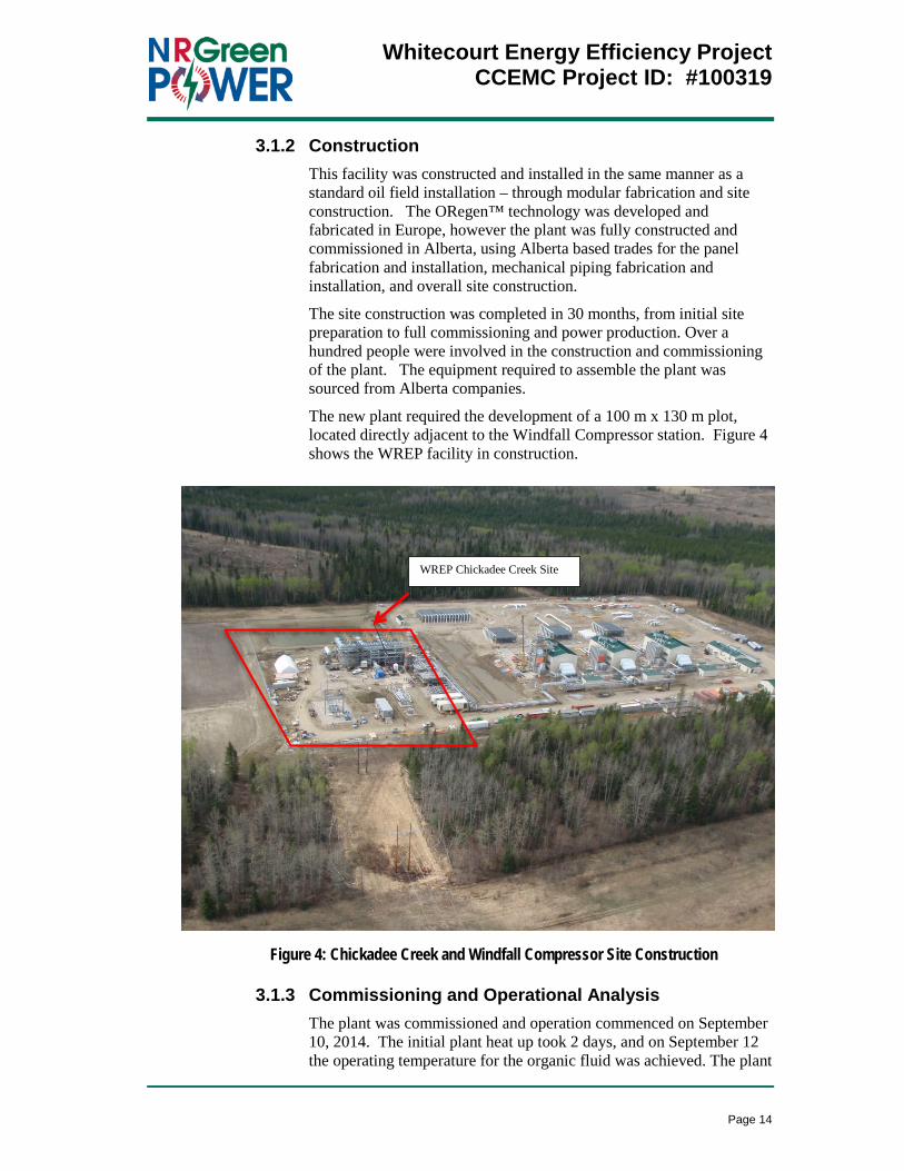
The new plant required the development of a 100 m x 130 m plot, located directly adjacent to the Windfall Compressor station. Figure 4 shows the WREP facility in construction.
Figure 4: Chickadee Creek and Windfall Compressor Site Construction
3.1.3 Commissioning and Operational Analysis The plant was commissioned and operation commenced on September 10, 2014. The initial plant heat up took 2 days, and on September 12 the operating temperature for the organic fluid was achieved. The plant
WREP Chickadee Creek Site
Whitecourt Energy Efficiency Project
CCEMC Project ID: #100319
Page 15
operated for 7 days post commissioning and was then taken off line to perform repairs on various components. The repairs were completed within 8 days.
Upon completion of the repairs, the plant operated intermittently until January 31, 2015. Intermittent operation was due to planned Altalink outages, operational conditions on the Alliance mainline and ongoing maintenance and repairs to the ORegen ™ plant. The plant went off line on January 31, 2015 due to issues with the dry gas seals in the turbo expander and the decision to replace the seal was made. This resulted in a 4 month outage.
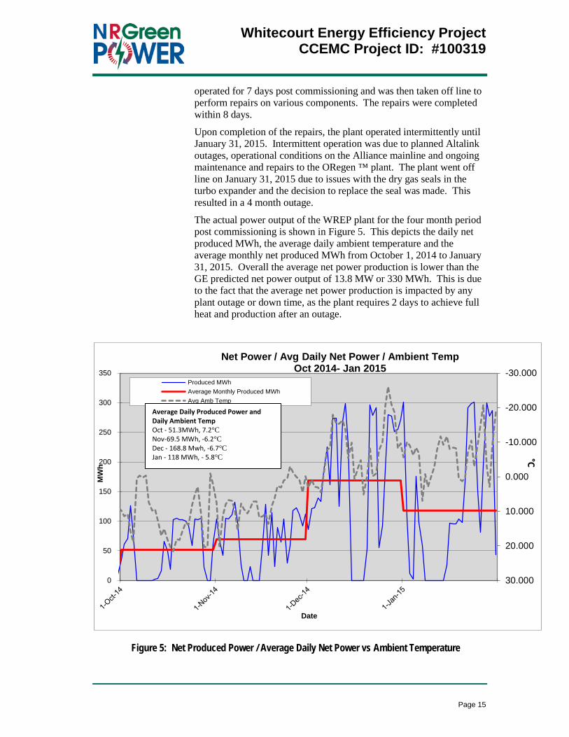
The actual power output of the WREP plant for the four month period post commissioning is shown in Figure 5. This depicts the daily net produced MWh, the average daily ambient temperature and the average monthly net produced MWh from October 1, 2014 to January 31, 2015. Overall the average net power production is lower than the GE predicted net power output of 13.8 MW or 330 MWh. This is due to the fact that the average net power production is impacted by any plant outage or down time, as the plant requires 2 days to achieve full heat and production after an outage.
Figure 5: Net Produced Power / Average Daily Net Power vs Ambient Temperature
-30.000
-20.000
-10.000
0.000
10.000
20.000
30.0000
50
100
150
200
250
300
350
MW
h
Date
Net Power / Avg Daily Net Power / Ambient Temp Oct 2014- Jan 2015
Produced MWhAverage Monthly Produced MWhAvg Amb Temp
°C
Average Daily Produced Power and Daily Ambient Temp Oct - 51.3MWh, 7.2°C Nov-69.5 MWh, -6.2°C Dec - 168.8 Mwh, -6.7°C Jan - 118 MWh, - 5.8°C

Whitecourt Energy Efficiency Project
CCEMC Project ID: #100319
Page 16
The following table illustrates the power ramp up after a plant outage on December 24, 2014. The plant was restarted at 06:30 on December 24 and operated until an outage on January 2, 2015. The plant warm up was not completed and full power output was not achieved until December 27, 2015.
Table 3: WREP Net Power Output Dec 24, 2014 to Jan 2, 2015
Total Net
MWh Total hrs
operational Net MW
(Based on operating
hours)
Average Ambient Temp
°C
Dec 24, 2014 55.5 8 6.7 0.3 Dec 25, 2014 91.5 10 9.2 -7.1 Dec 26, 2014 186.3 18 10.4 -10.5 Dec 27, 2014 279.5 24 11.6 -3.0 Dec 28, 2014 277.2 24 11.5 -9.3 Dec 29, 2014 251.6 24 10.5 -15 Dec 30, 2014 254.8 24 10.6 -20 Dec 31, 2014 271.2 24 11.3 -3 Jan1, 2015 300.7 24 12.5 +3 Jan 2, 2015 106 12 8.8 -9

Whitecourt Energy Efficiency Project
CCEMC Project ID: #100319
Page 17
°C
Figure 6: WREP Net Power Output vs Ambient Temperature
The analysis of the operational data over the 10 day period from December 24, 2014 to January 2, 2015, shows that after the initial warm up phase, the efficiency of the ORegen ™ plant is dependent on the ambient temperature during operation. As the temperature approaches 5°C, the power production approaches the GE predicted net power output of 13.8 MW. Decreases in temperature correlate to decreases in power production, even once the plant has reached operating temperature. This is evident from December 28 – 30 when the average ambient temperature dropped to -20°C and the net power produced dropped to an average of 10.5 MW. However, when the temperature rose to +3°C on January 1, 2015, the net power produced increased to 12.5 MW. This is shown graphically in Figure 6.
The conclusion based on the limited data analysis is that even though the organic fluid was selected to increase efficiency under the WREP operating conditions, the actual plant efficiency is dependent on the ambient operating temperature.
-20
-15
-10
-5
0
5
10
6
8
10
12
14
16
24-Dec-14 26-Dec-14 28-Dec-14 30-Dec-14 01-Jan-15
MW Average Ambient Temp °C
WREP NET POWER OUTPUT VS AMBIENT TEMPERATURE DEC 24, 2014 - JAN 2, 2015
°C MW
Whitecourt Energy Efficiency Project
CCEMC Project ID: #100319
Page 18
3.1.4 Lessons Learned The lessons learned during the WREP project were mainly due this being the first ORegen™ project ever constructed. The lack of previous projects or prototyping resulted in issues due to actual operating conditions that were not anticipated in the design of the project. The following items were identified as major lessons learned and impacted the start up and operation of the plant. Application of the resolutions will ensure the successful execution of future projects.
1. Cyclopentane leakage from Preheater girth Flange.
Cyclopentane leakage was found on preheater equipment during the initial start up activity. To resolve this, the equipment was dismounted, inspected and the original cyclopentane tube-sheet was replaced.
2. Blowcase and process drainages management.
The blowcase was designed to hold any cyclopentane liquid drop out that occurred during plant shut down. Once the plant was shut down, some liquid cyclopentane would drop out of the vapour state and due to the piping configuration, travel back to the outlet of the LP side of turbo expander. This liquid needs to be removed prior to start up.
Upon start up, it was determined that the cyclopentane drainage volume was too high to be managed with the existing blowcase configuration. To resolve this, the blowcase was replaced with a dedicated pump system to meet the requirements.
3. Cyclopentane pump seals damage.
The cyclopentane pump seal was broken two times during pump operation, due to impurities and dirt in the cyclopentane. This was thought to be introduced into the fluid due to mill scale and pipe rust which is common in piping. To resolve this, the seals were replaced with ones that are capable of operating under the actual fluid conditions.
4. Dry gas seals of Turboexpander
The dry gas seal system on the Turbo Expander failed. This is currently being resolved by the installation of a new dry gas sealing system which uses nitrogen as a seal gas and a redesigned seal system for this application.

Whitecourt Energy Efficiency Project
CCEMC Project ID: #100319
Page 19
3.1.5 Application The GE Oil & Gas ORegen™ technology addresses the goals of the CCEMC by addressing climate change in the following:
Allows Alliance Pipeline to capture the lost energy in the hot exhaust from its natural gas fired compressors and conserve this energy so that it can be sold and convereted into electricity.
Providing stable baseload electrical generation to the Alberta Electical grid, reducing the requirement for fossil fuel generation.
Produces no new emmissions as the existing compressor operation is not altered.
Uses no incremental fuel for opeartion, requires no water and has no discharges, thereby conserving resources.
The GHG offsets can be utilized by Alliance to fullfil its obligation to reduce GHG emmissions from its operaterions in Alberta.
Whitecourt Energy Efficiency Project
CCEMC Project ID: #100319
Page 20
4.0 GREENHOUSE GAS AND NON-GHG IMPACTS
4.1 GHG Benefits Resulting From the Completed Project Electricity generation accounts for approximately one-quarter of Alberta’s greenhouse gas (GHG) emissions (Bell and Weiss, 2009, p.1). In order for Alberta to achieve meaningful reductions in GHG emissions while maintaining a vibrant economy, more efficient means of electrical generation is needed. Waste heat recovery is one method of achieving these reductions.
NRGreen evaluated a number of technologies (in particular steam and pentane) and execution approaches to develop projects using waste heat from Alliance’s Windfall compressor station. When considering the capital cost, operating requirements and generation potential, NRGreen concluded that using an efficient application of an organic rankine cycle was most appropriate and implemented the ORegenTM system. The ORegenTM system generates electricity using energy from fuel that has already been expended for its primary purpose (natural gas transmission) without materially impacting operations at Alliance’s Windfall Compressor Station. The heat that would have otherwise been exhausted is instead captured as useful energy and used to generate electricity. This, in turn, reduces the combustion of fossil fuels that would have otherwise occurred to generate the equivalent quantity of electricity.
4.2 Expected Annual GHG Benefits Projected Over a Ten-Year Period The expected lifetime of WREP and its installed technologies is 20 years. Although electricity generation and its associated environmental benefit will occur for the entire lifetime of the project, offset credits will be generated for the maximum allowable credit duration prescribed by Alberta Environment. Within the current system, offset credits will be generated for a period of 8 consecutive years from the credit start date of December 8, 2014 with a possible 5-year extension to December 8, 2027. During the 8 to 15 year credit duration period, financial benefit will be realized through the generation of emission offset credits.
The project is estimated to produce 70,000 tonnes of carbon dioxide equivalent (CO2E) offsets per year under normal operation. The actual calculated CO2E reduction for 2014 is 6,000 tonnes and for 2015 is estimated to be 19,000 tonnes respectively due to the project start date, commissioning and start up time. For the credit period of 2016 to 2028, GHG emission reductions are estimated to be 910,000 tonnes. A full 15 years of credit production will result in estimated GHG reductions of 935,000 tonnes.

Whitecourt Energy Efficiency Project
CCEMC Project ID: #100319
Page 21
Table 4: Projected Generation on Emission Offset Credits
Projected Generation on Emission Offset Credits Based on the Alberta Electricity Grid Factor of 0.65 tonnes CO2E/MWh
Year GHG Reductions (tonnes CO2E/year)
Year GHG Reductions (tonnes CO2E/year)
1 2014 6,000 8 2021 70,000 2 2015 19,000 9 2022 70,000 3 2016 70,000 10 2023 70,000 4 2017 70,000 11 2024 70,000 5 2018 70,000 12 2025 70,000 6 2019 70,000 13 2026 70,000 7 2020 70,000 14 2027 70,000
15 2028 70,000 Total 935,000
4.3 Non-GHG Benefits Resulting From the Completed Project
4.3.1 Economic Impacts The ORegenTM technology, once proven commercially with WREP, is scalable and can be applied to other industrial process where sources of waste heat energy are available in Alberta (i.e. other pipelines, existing gas fired electrical generators, gas processing plants, oil sands production, etc.).
WREP will create the opportunity for additional technical training of existing personnel, potentially develop a secondary industry associated with operation and maintenance of the facility and enhance research on waste heat recovery. The need for qualified personnel will only increase as the technology is used in subsequent projects.
4.3.2 Environmental Impacts The minimal environmental impact of WREP coupled with the emission offsets it produces strongly encourage the development of similar waste heat recovery installations in the future. The environmental impacts associated with WREP are described below and it is expected that future waste heat recovery installations can be realized with similar low environmental impact.
4.3.2.1 Land
Alliance’s Windfall Compressor station lies on an area previously stripped of topsoil and resurfaced with gravel. The ORegenTM system is installed on the existing graveled, previously disturbed site; a small amount of additional disturbance beyond the facility site was required to allow machinery to work in and around the waste heat unit during construction. As such, the North fenceline of the site was

Whitecourt Energy Efficiency Project
CCEMC Project ID: #100319
Page 22
moved north by approximately 20 meters. Topsoil from this area was properly stripped and stored according to Alliance’s soil handling guidelines. Temporary disturbances during construction included increased vehicular traffic to and from the site and additional airborne dust and exhaust.
4.3.2.2 Water
There is no water use or process discharge associated with the operation of WREP. Site runoff at the Windfall compressor station is controlled and maintained on site. In the event of a catastrophic failure, products used as part of the waste heat recovery cycle (thermal oil, lubricating oil) will drain to the existing retention pond through ditches built around the perimeter of the facility.
4.3.2.3 Air
Aside from the intermittent operation of an Auxiliary Power Unit (APU), there are no new GHG emissions generated by WREP.
4.3.2.4 Biodiversity
Comprehensive wildlife surveys were conducted along the Alliance pipeline system in 1997 and 1998 as a part of the Greenfield project environmental assessment. Species of concern were not previously observed within the immediate vicinity of the Windfall Compressor Station during the Greenfield project assessment or during pipeline construction or operations.
The project is located on an ungulate winter range with moderate potential for moose, elk and deer, but it has not been designated an ungulate key habitat due to its location adjacent to Highway 43, other rights-of-way and facilities.
4.3.2.5 Noise
A noise impact assessment was conducted to predict the sound levels associated with WREP. Concurrent operation of Alliance’s Windfall compressor station and WREP does not exceed the AUC nighttime permissible sound level.

Whitecourt Energy Efficiency Project
CCEMC Project ID: #100319
Page 23
5.0 OVERALL CONCLUSIONS
The installation of the GE Oil & Gas ORegen™ System for Waste Heat Recovery for the Whitecourt Recovered Energy Project (WREP) was successful in utilizing the waste heat from Alliance’s Windfall Compressor station site to generate electricity with limited additional environmental impacts.
As this is the first ORegen™ system, there have been start up and operational issues, which has impacted the ability to consistently produce power. These issues continue to be resolved today and GE anticipated that the completion of the dry gas seal gas conversion to nitrogen will resolve the final operational issue and allow for full plant production. Ensuring the application of the lessons learned during this project for future projects will assist in a successful field execution, commissioning and start up.
Based on the analysis of available data the WREP plant generates an average of 10-12.6 MW of net power during full operation. This is within 70-90% of the original projected power generation. Power generation is impacted by the average ambient temperature, and full power generation was only achieved when the ambient temperature was at or below the optimal temperature of 5°C, resulting in lower than predicted generation. Further analysis of operating data under a range of temperatures will be completed once the plant is fully operational, and it is anticipated that the plant will operate within 90 – 100% of project power.
Operation of the Alliance compressors at Windfall 100% of the time, combined with the 98.8% availability of WREP, results in approximately 125 GWh annual net power production. This equates to the creation of approximate 70,000 tonnes /yr of GHG offsets, potentially offsetting 935,000 tonnes CO2E over 15 years. The positive economic and environmental impacts of WREP will be realized well beyond its life expectancy through positively reinforcing the benefits of waste heat recovery in industrial applications and positively encouraging the movement toward sustainable electricity development in Alberta.

Whitecourt Energy Efficiency Project
CCEMC Project ID: #100319
Page 24
6.0 SCIENTIFIC ACHIEVEMENTS The results of the project funded by the CCEMC were presented at industry conferences, published in industry journals and industry reports. In addition, GE has obtained 6 patents relating to the development of this project.
6.1 Patents
Docket Number Docket Title Title DWPI - Title External link
233509 High-Pressure ORC Cycle with Near-Critical Boiling
DIRECT EVAPORATOR SYSTEM AND METHOD FOR ORGANIC RANKINE CYCLE SYSTEMS
Power generation system using an Organic Rankine Cycle (ORC), has heat exchanger made to receive an ORC fluid at single inlet as a pressurized liquid at a pressure greater than or equal the critical pressure of ORC fluid
https://www.google.com/patents/US20130133868
233702 Generation 2 Direct Evaporator Cyclopentane ORC
ORGANIC RANKINE CYCLE SYSTEM AND METHOD
Organic Rankine cycle (ORC) system for e.g. gas turbine has preheater that receives the elevated temperature waste heat fluid from the superheater and allows heat exchange with a relatively lower temperature working fluid in a liquid state
https://www.google.com/patents/US8240149
233728 Protective Staging Technology for Limiting Film Temperature Through Configuration of HXR Sections
DIRECT EVAPORATOR APPARATUS AND ENERGY RECOVERY SYSTEM
Direct evaporator apparatus for organic Rankine cycle energy recovery system used in e.g. small-scale gas turbine, has heat exchange tube with inlet and outlet in direct fluid communication with preheater and superheater zones, respectively
https://www.google.com/patents/EP2348200
233729 Heat Exchanger for Direct Evaporation in ORC Systems with Coating for Enhanced Nucleate Boiling
HEAT EXCHANGER WITH SURFACE-TREATED SUBSTRATE
Organic rankine cycle system for recovering and utilizing waste heat from waste heat source by using closed circuit of working fluid, comprises evaporator comprising surface-treated substrate for promoting nucleate boiling of working fluid
https://www.google.com/patents/EP2423475
240796 Dual-Reheat Rankine Cycle with Active Condensation Temperature Control
DUAL REHEAT RANKINE CYCLE SYSTEM AND METHOD THEREOF
Double reheat Rankine-cycle system has low temperature unit that circulates evaporation stream of working fluid from high temperature unit
https://www.google.com/patents/US8459029
241323 Direct evaporator heat exchanger for ORC with internal heat exchange capability
DIRECT EVAPORATOR APPARATUS AND ENERGY RECOVERY SYSTEM
Direct evaporator apparatus for use in organic rank- inc cycle energy recovery system, has heat exchange tube positioned within heat source flow path, where portion of gas in contact with portion of tube is in thermal contact with gas
https://www.google.com/patents/US8511085
6.2 Presentations (Oral) 1. Cinelli, F., Leher, M., Miliani, A., Seghi, G. Reducing the CO2 Footprint
by Means of Overall Cycle Efficiency Increasing. Presented at GASTECH 2009 in
Abu Dhabi, May 25-28, 2009.

Whitecourt Energy Efficiency Project
CCEMC Project ID: #100319
Page 25
2. Asti, A., Bacci, A., Del Greco, A.S., Del Turco, P.,Landi, G., Seghi, G. The ORegenTM Waste Heat Recovery Cycle: Reducing the CO2 Footprint by Means of Overall Cycle Efficiency Improvement. Presented at ASME Turbo Expo 2011 in Vancouver, British Columbia, June 6-10, 2011.
6.3 Published Industry Journals 1. Cinelli, F., Leher, M., Miliani, A., Seghi, G. Reducing the CO2 Footprint
by Means of Overall Cycle Efficiency. 2. Burrato, A. The ORegenTM Waste Heat Recovery System to Reduce CO2
Emissions and Increase Plant Efficiency. GE Oil & Gas Technology Insights, 2013.
6.4 Industry Reports 1. Post Guillen, D., Zia, J. Modifications and Optimization of the Organic
Rankine Cycle to Improve the Recovery of Waste Heat. Idaho National Laboratory, September 2013.

Whitecourt Energy Efficiency Project
CCEMC Project ID: #100319
Page 26
7.0 NEXT STEPS Once the WREP plant reaches full operation, NRGreen will analyze and review the data to determine the feasibility of implementation at other Alliance compressor sites that are not already equipped with waste heat recovery generation.
GE has sold 4 ORegen™ units over the past five years and plans to apply the lessons learned for the implementation of the following projects:
1- ORegen ™ unit for Berakas Project in Brunei Darussalam (16 MW)
1- ORegen ™ unit for Saiyok Waste Heat recovery in Thailand (16 MW)
2 -ORegen ™ units for Hongliu project in China (16 MW each)
GE also plans to approach the market to introduce two new sizes of the ORegen ™ plant, an 8.5 MW and a 2.0 MW. Both of these plants will be suitable for mechanical drive and power generation.

Whitecourt Energy Efficiency Project
CCEMC Project ID: #100319
Page 27
8.0 COMMUNICATIONS PLAN The technology behind the GE Oil & Gas ORegen™ System for Waste Heat Recovery has been broadly communicated through industry conferences, GE Oil & Gas literature and in the press.
http://www.ge-spark.com/spark/nrgreen/en/video/
http://site.ge-energy.com/businesses/ge_oilandgas/en/prod_serv/serv/oregen.htm
https://www.youtube.com/watch?v=lvaBDOl-nXQ
http://www.greencarcongress.com/2011/11/first-application-of-ge-oregen-organic-rankine-cycle-waste-heat-recovery-system-at-alliance-pipeline.html
http://www.ge-spark.com/spark/resources/whitepapers/Reducing_CO2_Footprint_by_Cycle_Efficiency.pdf
http://www.businesswire.com/news/home/20090127006179/en/Power-Emissions-Key-Features-Newly-Certified-Ecomagination#.VWxvNVTnboo

Whitecourt Energy Efficiency Project
CCEMC Project ID: #100319
Page 28
9.0 ABSTRACT AND KEYWORDS The Whitecourt Recovered Energy Project (WREP) Station is the construction of a waste heat recovery generation system within the Alliance Pipeline Windfall Compressor station site. NRGreen Power undertook the installation of the GE Oil & Gas ORegen™ System for Waste Heat Recovery to produce 13.8 MW of net power into the Alberta Electrical Grid.
The ORegen™ System maximizes the Organic Rankine Cycle efficiency through a thermodynamic superheat cycle that recovers waste heat from gas turbine exhaust. This is the first installation of the GE ORegen™ System for Waste Heat Recovery.
The Windfall compressor station runs nearly 100% of the time and it is anticipated that the waste heat recovery system will operate approximately 98.9% of the time, producing up to 125 GWh of net power annually into the Alberta electrical grid. This equates to the creation of approximate 70,000 tonnes /yr of GHG offsets. Based on a full 15 years of credit production, the WREP project has the potential to offset 935,000 tonnes CO2E, through the generation of 2,500 GWh of electricity.
GE Oil & Gas plans to introduce the ORegen ™ technology to the market, creating a reference with a major customer that can be leveraged for future projects both inside and outside of Canada. GE also plans to apply the operational experience gained in this project to improve overall plant performances for future projects.
The positive economic and environmental impacts of WREP will be realized well beyond its life expectancy through positively reinforcing the benefits of waste heat recovery in industrial applications and positively encouraging the movement toward sustainable electricity development in Alberta.
Keywords:
NRGreen
Alliance Pipeline
GE Oil & Gas
ORegen ™ System for Waste Heat Recovery
Organic Rankine Cycle