Embed Size (px)
Citation preview

Novel Needle Guide for Preoperative Wire-Guided Localization of Breast Lesions
Colin Schrof, First Author University of Wisconsin - Madison, Department of Biomedical Engineering 671 Broken Arrow Rd. Chanhassen, MN 55317 [email protected] Gopika SenthilKumar, First Author University of Wisconsin - Madison, Department of Biomedical Engineering 1900 Norhardt Dr. Apt 115, Brookfield, WI 53045 [email protected] Kevin Fantl, First Author University of Wisconsin - Madison, Department of Biomedical Engineering W247N5915 Grouse Ct., Sussex, WI 53089 [email protected] Kari Borowski, First Author University of Wisconsin - Madison, Department of Biomedical Engineering N21W29750 Glen Cove Rd., Pewaukee, WI 53072 [email protected] Alexander Henry, First Author University of Wisconsin - Madison, Department of Biomedical Engineering 8309 S 68th Street, Franklin, WI 53132 [email protected] Dr. Lonie R. Salkowski, [CONFIRM AUTHOR STATUS] UW Madison School of Medicine & Public Health, Departments of Radiology and Medical Physics 600 Highland Avenue, Madison, WI 53792-3252 [email protected] Dr. Beth Meyerand, [CONFIRM AUTHOR STATUS] University of Wisconsin - Madison, Department of Biomedical Engineering/UW Health [CONFIRM AFFILIATION] [INSERT ADDRESS] [email protected] Dr. Frederick Kelcz, [CONFIRM AUTHOR STATUS] UW Health/ UW Breast Center [CONFIRM AFFILIATION] [INSERT ADDRESS] [email protected]

Abstract
Lumpectomy, surgical removal of the lesion is the standard treatment for patients with early-stage or small breast cancers [1]. Most lumpectomies are preceded by a tumor localization procedure that can be performed using various methods. One method is by using mammography for Image guided localization (IGL). IGL involves localizing the lesion using a fine wire with a hook to assist the surgeon in identifying non-palpable lesions [4,5]. IGLs are a manual technique, depending heavily on the radiologist's skill level. The procedure takes approximately 15 to 45 minutes to place the wire(s) depending on the complexity of the case. Often this can result in multiple corrections of the needle placement prior to wire deployment to ensure that the wire(s) properly localizes the lesion for surgical removal [4]. Our team has designed a needle guide that can streamline the process and reduce variability between physicians. The guide is a single-handed, ring-based model that can be removed from the imaging area with ease to prevent interference with the X-ray. The hinges and cylindrical composition of the guide stabilizes the needle and ensures accurate needle puncture during the first try; its conical bottom opening allows the clinician to easily locate the initial marking on the patient, and the countersink allows for maximum assisted-puncture. Pilot testing on a phantom breast model was performed by a radiologist and two undergraduate students. Results showed that the guide maintained accuracy on the first insertion regardless of skill level and is effective at all regions of the breast model. Further understanding of its benefits over the standard procedure, as well as to test whether the guide improves procedures performed by new and/or inexperienced clinicians, will be studied in the future. The objective of this article is to introduce a novel needle guide that helps streamline the pre-lumpectomy, image-guided breast lesion localization procedure.

I. Introduction
Breast cancer is the leading cause of cancer death in women [6]. The standard of care for patients with early-stage or small breast cancer is a conservative surgical approach to remove only the cancerous tissue and some surrounding healthy tissue while preserving the breasts (i.e. lumpectomy) [1]. Tumors that are best seen on mammography undergo a mammographic-image based wire localization procedure in which the lesion is localized using a needle containing a fine wire with a hook, so the surgeons can identify the location of non-palpable lesions during the lumpectomy procedure [4,5]. The current method for performing the procedure, is a manual technique that often requires multiple corrections and x-ray images; this contributes to patient discomfort, pain, and anxiety [5]. In this paper, we introduce a novel needle guide that streamlines image-guided localizations (IGL) and increases accuracy of initial puncture, thereby reducing the need for numerous x-ray images, corrections, and procedure time.
1.1 Mammography Guided Wire Localization Procedure
Preoperative procedures for localizing non-palpable breast lesions are often performed with mammographic guidance. While numerous other methods for localization such as the Radioguided Occult Lesion Localization and Radiolabeled Seen Localization are being studied, image-guided wire localizations (IGL) remains the gold-standard preoperative localization procedure [5,7]. During IGL, the lesion is first identified by taking a mammographic image with the breast under compression (Figure 1.A). If a biopsy was performed, a titanium clip is left at the region of interest and this clip can also be used a marker for localization.
The breast is compressed with a fenestrated plate that displays an alphanumeric-label at the margins of the window which the radiologist can use to identify the location of the lesion (or titanium clip) in the XY plane (Figure 1.B). After marking this location, it is anesthetized with the injection of a local anesthesia such as lidocaine. Next a needle housing a fine wire with a hook is inserted with assistance both from the light source shining down from the top (craniocaudal projection) of the mammography machine and the shadow created by the needle hub. The hub creates a square shadow on the breast with which the physician can center the needle to insert it perpendicularly (Figure 1.C). Once the needle is inserted, another X-ray is taken to determine if the needle intersects lesion, or area of interest, within the square of the needle hub (Figure 1.D). The accuracy tolerance of this insertion is typically considered to be up to 1 cm from the lesion (or titanium clip) [8]. If the intersection does not meet the margin, the needle must be backed out and realigned with another X-ray taken after each adjustment. After proper location this imaging plane, the imaging head is then rotated orthogonally and the patient’s breast is put into lateral-medial compression for another X-ray to evaluate the depth of the needle (Figure 1. E). The depth of the needle is adjusted by pulling the needle out of the breast to optimally localize the lesion. Once the

radiologist is satisfied with the localization, the needle is removed, and the wire is left inside the breast, after which the patient is transported to the operating room.
This procedure can also be performed starting in the lateral projection and later imaging in the craniocaudal project. Overall this procedure needs two orthogonal imaging planes to ensure the accuracy of wire placement in 3D space. The surgeon uses the mammography images with the hook-wire inside as seen in figure 1.F, as well as the exposed wire, to plan the incision and remove the lesion. The procedure is performed by radiologists the day of the planned lumpectomy, takes approximately 30 to 45 minutes [4,5].
Figure 1: The images above show a few of the important steps of IGL. A: Image of a breast
phantom in compression with the mammography machine. B: X-ray image tumor location and alphanumeric grid. C: The hub of the needle creating a shadow on the breast phantom. D: Top image with needle, wire and hub. E: Lateral compression of a phantom breast with localization
needle and wire. F: Final image with wire-placement after needle removal. 1.2. Drawbacks of Current IGL

The current method for performing IGL is highly manual, often requiring numerous corrections and images; the quality of procedure also depends on the skill level and experience of the radiologist. This introduces variability in the quality of care patients receive depending on the expertise of the radiologist. Additionally, patients have an increased risk of vasovagal reactions (due to fasting and associated anxiety), complain of discomfort from the long duration of the procedure, and show high anxiety from having a major procedure performed right before surgery [5]. The time required for the current procedure also introduces scheduling problems and limits the number of patients that can effectively be treated [5]. Therefore, it is essential that the procedure is streamlined and made more efficient while improving accuracy of lesion localization. 1.3 Competing Devices In 2003, a grid system with holes for needle insertion was recommended by researchers from the University General Hospital, Murcia, Spain [8]. However, the system is not shown to be widely used clinically since it does not guide the needle insertion to ensure accurate localization (i.e. procedure is still mostly free-handed), still relies on radiologist skill level, adds time for adding the plate into the procedure, and introduces high barrier of introduction since it requires the clinicians to change their current training and methods significantly. Numerous studies have also suggested methods for improving the wire and hook, compression mechanism of the breast, as well as insertion directions or tactics, however the procedure is still extensive and continues to have the drawbacks described in section 1.2 [10-18]. 1.4 Efficacy of Needle Guides in improving other related-procedures Needle guides have been introduced in the ultrasound-guided biopsy procedure, and clinical studies have shown their usefulness in improving accuracy, standardizing care, lowering time of procedure, and reducing errors in both experienced and inexperienced operators [19,20]. We are confident that our needle guide will provide similar benefits in improving the IGL procedure.
II. Functional Requirements The needle guide must assist with the localization process by allowing for exact orthogonal needle alignment by the physician to ensure accuracy of procedure (Figure 1.D). This product must be compatible with the current mammography machine and procedures that are used, and have a low barrier to introduction in the clinics. In addition, the device must be safe for the physician and the patient. Along with safety, the product must be easily sterilized after manufacturing, and have a low enough cost for one-per-patient use. It must also be ergonomic, easy to use, withstand drops and pressure from use.

Table 1. Primary criteria for the design of the rapid needle alignment device in order of relative
importance/significance.
III. Needle Guide Design Description
The assistive needle localization guide we propose for use with the mammography machine is shown in Figure 2. It consists of two pieces, connected by a pin inserted into a pin hinge. In use, it is designed to be single-use to ensure sterility and minimize durability concerns. This design was finalized after 6 iterations of 3D printed guides followed by physician client validation.
Figure 2. 3D SolidWorks models of the front and back of the needle guide placed on the fenestrated plate in its functional insertion position (on a scale model of the fenestrated plate). The radiologist will insert the needle into the countersink region at the top of the guide until the desired depth has
been achieved.

3.1 Mechanical Specifications
Our final design of the needle guide incorporates a handheld design to achieve perpendicular, accura puncture during localization. This is enacted by the use of two flanges which use reference points on the fenestrated compression plate to rest on. The needle is inserted through a tubular chamber in the center of the guide, between the flanges. This chamber is prefaced with a large countersink to provide both an easy aiming experience for the physician and a maximal insertion depth without reducing mechanical stability. At the bottom of this chamber, there is a cone which comes down to the point where the needle exits the chamber. This allows for easy and ergonomic aiming of the mark on the patient. On either side of the insertion chamber, two large holes exist for the user to place their fingers into. This, alongside the hinge, will allow for single-handed use, which allows for easy integration into the current procedure. The pin hinge was incorporated to prevent out-of-plane rotation, providing additional stability. Finally, the edges of the guide are rounded to provide a smooth finish for comfortable use. The prototype was 3D printed with Grey Pro SLA resin for easy hinge rotation while ensuring strength. For clinical implementation, Dental SG resin, which is autoclavable and Class 1 biocompatible, will be used [23]. This device has been designed to be completely mechanical and disposable to provide ease of integration in the clinics and provide physicians with the option to not use it for highly unique or intricate patients.
IV. Methods
4.1 Preliminary Testing Preliminary testing was completed by a practiced physician who performed the localization procedure using the final needle guide design on silicone breast model rather than a human subject. The testing was performed on the Selenia Dimensions mammography machine: Hologic, Marlborough, MA [22]. During testing, the physicians first performed the free-handed IGL procedure using the overhead light’s shadow to guide the needle into the breast model and then utilized our device for IGL. The physician’s feedback regarding the comfortability of the device, ease of use, etc. was taken into consideration while drafting the clinical study. Additionally, a bubble tap was used to ensure the device maintained perpendicularity on the plate, and researchers observed the physician’s technique multiple times to ensure that the hinge worked well, the device was easy to remove, the countersink allowed for maximum insertion, and the removal of the device did not interfere with the accuracy or perpendicularity of insertion. Additionally, mammography images from the current method and after the use of our device was taken to assess the preliminary accuracy of our device. Finally, the efficacy of the silicone breast model for testing and objective metric measurement was analyzed.

4.2 Breast Model Development Trials with tissue explants, soft silicone models, and a number of gels were done to idealize a phantom breast model for IRB studies. The breast model material best suitable for the localization device testing was determined to be an elastomeric copolymer gel produced by Humimic Medical™. The properties of the gel allowed for numerous advantages including moldability, anatomically similar density, and reusability. In order to allow for simple X-ray imaging (i.e. mediolateral and craniocaudal images), the breast model was made in a cubical shape. The fabrication steps shown in Figure 3 illustrate the melting and molding process utilized to produce the final model. First, the clear raw gel is melted down at approximately 230 degrees fahrenheit until liquified. Once the gel is in its liquid state, concentrated flesh tone pigment dye is added at approximately 2% by weight. This allows for the phantom to be opaque for the purposes of the study. Lastly, the homogeneous gel is removed from the heat source and immediately poured into a 4 inch x 4 inch x 4 inch aluminum mold. After being left to harden and cool for 18-24 hours, the elastomeric gel is usable for the study and can be remolded for extended use.
Figure 3: Images depicting breast model fabrication steps. A: (Left) Liquified gel at 230 degrees Celsius. B: (Center) Pouring flesh-toned gel into aluminum. C: (Right) Semi-solid phantom gel
during hardening process. 4.3 Device Validation The finalized device and the newly developed breast model were tested by a radiologist and two undergraduate students. A titanium clip was inserted and its location was marked with a pen (shown in figure 4). Then the breast model was moved to top right, top left, bottom right, bottom left, and middle of the fenestrated plate, and all three participants performed the localization procedure using

the guide. A top (CC) and side image (ML) were taken for each localization. The distance from the needle to the clip on all images were analyzed for each image.
Figure 4: Breast model with marking at clip location with needle inserted at mark.
4.4 Clinical Testing To determine the effectiveness of the proposed localization needle guide compared to the traditional freehand method, we received IRB approval for clinically testing the device. The testing set-up is identical to the set-up used in the current methodology of a needle localization procedure, except a phantom breast model will be used in the place of a patient. The newly developed breast model will be in a hospital or clinic room with a radiologist, a mammography machine, and any other support staff necessary for the localization procedure. Breast models will be randomly assigned to each phase (control vs. experimental). Each physician participating will complete both phases of the study. The study subjects will be any hospital staff trained to perform the needle localization procedure. They will first take a pre-study survey reporting their current experience with the procedure and amount of training received. Next, the subjects perform the standard localization procedure while the researchers record the following metrics: time from initial needle puncture to final removal, total procedure time, and number of corrective images taken during procedure. Next, the subjects are trained to use the needle guide using a standard training protocol. They are all given 15 minutes maximum for training. Then, they perform the procedure with our needle-guide while the researchers measure the same metrics. After all the subjects finished with testing, we analyzed the

accuracy of needle puncture in the final medio-lateral images; the researcher performing the analysis was blinded to the images. 4.5 Statistical Analysis PRISM GraphPad v8 was used to perform paired t-tests for procedure times, accuracy, and number corrections. For comparing between participants, unpaired t-test was used (figure 6D). The values are reported on bars in the graphs.
V. Preliminary Testing Results
Figure 5: Mammographic images from testing using silicone breast phantom model. A: Top-image from free-hand localization. B: Image from mediolateral compression after free-hand localization.
C: Top-image from guide-assisted localization. D: Image from mediolateral compression after guide-assisted localization.
The physician was very well trained and performed the free-handed localization procedure with ease. However, after the physician performed the procedure with the needle guide device, it was found that the number of corrections and x-ray images used as well as procedure time was higher during the free-handed procedure. Since this testing was purely for fine-tuning our device and clinical testing procedure, those numbers/ times are not reported. During the needle-guided procedure, a bubble-tap proved that the needle guide’s horizontal surface was aligned parallel with the plate, thereby proving that the cylindrical component of the guide was perpendicular the plate. The physician inserted the needle through the middle of the countersink into the model until the hub was impeded from further penetration. After insertion, the physician easily removed the device from the fenestrated plate without affecting the needle, thereby verifying the functionality of the hinge mechanism as well as the ease of integration into the current procedure. The physician did not have any discomfort free-handing the last part of the needle after device removal. The final figures taken

after the freehand technique and the needle-guide showed similar accuracy (Figure 5). Effectively, this testing verified that the needle guide stably holds the needle in an orthogonal position relative to the fenestrated plate, is usable with one hand, is stable in guiding the needle, lowers the number of corrections and the time required for the procedure, and has a low barrier to introduction in the clinics. Additionally we discovered problems with our current breast model and decided to develop a new model as described below as described in the methods for the actual clinical testing. The silicone breast model used for preliminary testing had a tendency to accordion-out when taken out of compression for imaging the medio-lateral orientation. Thus, there was variability in how the breast was re-compressed for the second image. In a real patient, this is not a problem since the breast cannot freely rotate; therefore, we decided that our model will need to be a cube that is less compressible, so we can ensure that the model orientation is standardized between testing subjects.
VI. Device Validation Results
Figure 6: The needle was within 1mm from the clip in all CC or top images. B: The distance between the needle and clip was less than 5mm in all ML or side images. C: Accuracy was

maintained at all locations on the fenestrated plates. D: Accuracy was not affected based on the level of participant’s previous training with the localization procedure ( free-hand and guide-based).
Validation of the device proved that the device maintains accuracy as shown in figure 6 A and B. We picked a 5mm threshold for side-image (ML) distance between the clip and the needle as per expert advice from our physician clients. For the top image, we used a 1mm threshold. The device also maintains accuracy at all locations on the fenestrated plate as shown in figure 6C. The slightly higher error in the right was due to the undergraduate students not the radiologist (data not shown). This could have been due to difference in handedness or the side of the plate the students chose to stand. It could also seem that way due to limited number of data points. Finally, the accuracy of localization was not affected by the prior training level of the participants (both free-hand and with the guide). Thus, our data seems promising in proving that the guide maintains accuracy regardless of skill level and location on the fenestrated plate.
VII. Clinical Testing Results
7.1 Quantitative Results
Figure 7: A: The needle insertion time was significantly decreased with the guide than free hand. B: The total procedure time was decreased with the guide than free hand.
Clinical testing of the needle guide proved the time efficiency of its use. Figure 7A depicts a significant decrease in the time from initial needle insertion to hand removal when comparing the

freehand technique to the use of the needle guide. Figure 7B suggests a decreasing trend in total procedure time when the guide is used.
Figure 8: The guide reduced both needle insertion time and total procedure time for 7/10 trials. The ratio of the two timing metrics between the trials with the guide to the free handed trials was calculated, and the results can be seen in Figure 8. The results reveal that the guide reduced both timing metrics for 7/10 trials, with the average percent reduction around 50%. Some of the guide trials reduced the these timing metrics by as much as 80%.

Figure 9: The reduction in procedure time and reduction in needle insertion time are positively correlated, with error bars shown as the dotted lines on the graph. As needle insertion time is
increasingly reduced, total procedure time also increasingly decreases. There is a strong positive correlation between the reduction in both time points taken during the study. This correlation can be seen in Figure 9. It proves that reducing the needle insertion process time itself is correlated to reducing the overall procedure time as well. It has been already stated that the guide significantly decreased needle insertion time, so the positive correlation in Figure 9 reveals the promising potential of the needle guide to decrease overall procedure time and consequently improve the efficiency of clinics.
Figure 10: The accuracy of the procedure was maintained within 5 mm using the guide for both the ML and CC X-ray images.
In order to be deemed an accurate procedure, the needle must be inserted within 5 mm of the titanium clip. Figure 10 suggests that all final images for all trials for both free handed procedures and guided procedures maintained that 5 mm accuracy. There was no statistical difference between the free handed and guided distances from the clip.

Figure 11: A: For 9/10 participants, they only needed to take 1 X-ray image before achieving an
accurate insertion. The number of images needed vs. number of images taken was quantified by examining the accuracy of all X-ray images taken, including each preliminary X-ray image prior to the final image the physician deemed accurate. The number of images needed, as depicted in Figure 11A, is how many images the participant theoretically would have needed to take prior to achieving a distance from the clip within 5mm. As seen in the figure, the number of images needed for the guided procedures were significantly less than the total number of images that were taken. This indicates that while participants were using the guide, they took more images than would be necessary to maintain accuracy while they were using the guide.
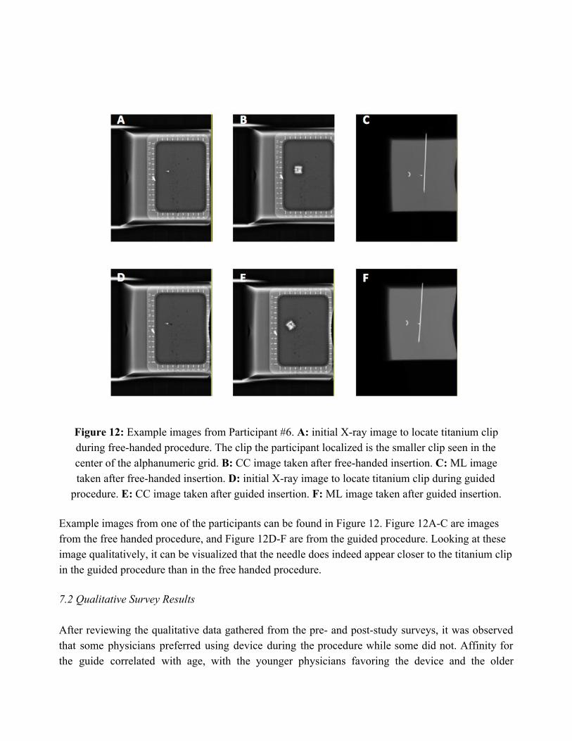
Figure 12: Example images from Participant #6. A: initial X-ray image to locate titanium clip during free-handed procedure. The clip the participant localized is the smaller clip seen in the center of the alphanumeric grid. B: CC image taken after free-handed insertion. C: ML image taken after free-handed insertion. D: initial X-ray image to locate titanium clip during guided
procedure. E: CC image taken after guided insertion. F: ML image taken after guided insertion. Example images from one of the participants can be found in Figure 12. Figure 12A-C are images from the free handed procedure, and Figure 12D-F are from the guided procedure. Looking at these image qualitatively, it can be visualized that the needle does indeed appear closer to the titanium clip in the guided procedure than in the free handed procedure. 7.2 Qualitative Survey Results After reviewing the qualitative data gathered from the pre- and post-study surveys, it was observed that some physicians preferred using device during the procedure while some did not. Affinity for the guide correlated with age, with the younger physicians favoring the device and the older

physicians preferring the traditional technique. Medical learning techniques, training time with the device, and study design may have an effect on device affinity as well. The breast phantom used in the study also may have an effect on the results as well. Noteworthy suggestions from the study subjects included softening the phantom to more accurately represent breast tissue. While this may not directly cause issues with the accuracy or efficiency of our device, it may cause an uncomfortable or unfamiliar experience while completing our study.
VIII. Conclusions and Future Work The primary goal of the needle guide is to streamline the IGL process in breast cancer treatment and reduce the variability in procedure between physicians by providing accurate, orthogonal needle alignment during puncture by the physician. Our hand-held ring design achieves this goal by incorporating two flanges that align on the localization plate perpendicularly, forcing orthogonal alignment of the needle. Our guide is 3D printed, features a hinge for stability, and utilizes a conical shape to guide the needle down to a specific point with accuracy in the range of a fraction of a millimeter. Secondary goals that were achieved in development include seamless integration into the current mammography machine, equipment, and procedures that are currently used, safety for the physician and the patient, ease of use, durability over repetitive use, and sterility. Our device became validated through our study as its accuracy was proven to be consistent regardless of experience level. Furthermore, the effectivity of our needle guide was confirmed through our clinical testing results. Use of the guide showed significant decreases in time compared to the free hand technique while accuracy was maintained. In addition, less images needed to be taken while using the guide in the study. These results suggest that our device would help to streamline the IGL process while increasing patient comfort and standardizing patient care. Through the examination of the qualitative assessment, it appears that affinity to the needle guide likely depends on age, procedure experience, medical learning techniques, and training time. Moving forward, the results reported in this paper would suggest that clinics that utilize this guide may see increases in care quality as well as cost savings due to greater time efficiency and reduced use of expensive imaging tools. Upon implementing this guide into clinics, we find it to be important that comprehensive training is completed prior to use on patients. IX. Acknowledgements This device was developed as a four-semester design project in the University of Wisconsin - Madison College of Engineering in the Department of Biomedical Engineering. It was developed during the courses Biomedical Engineering 300, 301, 400, and 402: Biomedical Engineering Design, headed by Dr. John Puccinelli. We are grateful to our client, Dr. Frederick Kelcz, and our two

advisors, Dr. Lonie Salkowski and Dr. Beth Meyerand, all having affiliations with UW Health (https://www.uwhealth.org) and the Department of Biomedical Engineering (https://www.engr.wisc.edu/department/bme). They have provided direction and support during these courses. We are also grateful to the University of Wisconsin-Madison College of Engineering for class space and the use of prototyping facilities. X. References
[1]"Breast Cancer - Treatment Options", Cancer.Net, 2017.
[2]L. Burt, J. Ying, M. Poppe, G. Suneja and D. Gaffney, "Risk of secondary malignancies after radiation therapy for breast cancer: Comprehensive results.", The Breast, no. 35, 2018.
[3]E. Obedian, D. Fischer and B. Haffty, "Second malignancies after treatment of early-stage breast cancer: lumpectomy and radiation therapy versus mastectomy.", Journal of Clinical Oncology, 2000.
[4]"Pre-Surgical Needle-Wire Localization - UCLA Radiology, Los Angeles, Westwood, Manhattan Beach, Santa Monica, CA", Radiology.ucla.edu, 2018.
[5] S. Dua, M. Keshtgar and R. Gray, "Strategies for localisation of impalpable breast lesions", The Breast, vol. 20, no. 3, 2018.
[6] R. L. Siegel, K. D. Miller, and A. Jemal, “Cancer Statistics, 2017,” Wiley Online Library.
[7] R. Gray, C. Salud, K. Nguyen, E. Duaway, J. Friedland, C. Berman, E. Peltz, G. Whiteland and C. Cox, "Randomized Prospective Evaluation of a Novel Technique for Biopsy or Lumpectomy of Nonpalpable Breast Lesions: Radioactive Seed Versus Wire Localization", Annals of Surgical Oncology, vol. 8, no. 9, 2001.
[8] J. Berna-Serna, J. Nieves, M. Madrigal and J. Berna-Mestre, "A new system for localization of nonpalpable breast lesions with adhesive marker plate", The Breast, vol. 13, no. 2, 2004.
[9]“Mammography - Canadian Cancer Society,” www.cancer.ca.
[10] M.J. Homer, “Localization of nonpalpable breast lesions: technical aspects and analysis of 80 cases,” AJR Am J Roentgenol, no. 140, pp. 807-811, 1983.
[11] M.J. Homer, “Nonpalpable breast lesion localization using a curved-end retractable wire,” Radiology, no.157, pp. 259-260, 1985.
[12] M.J. Homer Preoperative needle localization of lesions in the lower half of the breast: needle entry from below.” AJR Am J Roentgenol, no.149, pp. 43-45, 1987.

[13] D.B. Kopans, S. DeLuca, “A modified needle-hookwire technique to simplify preoperative localization of occult breast lesions.” Radiology, no. 134, p. 781, 1980.
[14] D.B. Kopans, K. Lindfors, K.A. McCarthy, J.E. Meyer, “Spring hookwire breast lesion localizer: use with rigid-compression mammographic systems.” Radiology, 157 (1985), pp. 537-538
[15] N.J. Parekh, J.N. Wolfe, “Localization device for occult breast lesions: use in 75 patients.” AJR Am J Roentgenol, 148 (1987), pp. 699-701
[16] J.D. Berná, V. Garcı́a-Medina, J. Pérez, C.C. Kuni, “A new apparatus for the localization of nonpalpable mammary lesions.” Eur J Radiol, 12, 1991.
[17] H.H. Chen, J.R. Bernstein, M.L. Paige, A.R. Crampton, “Needle nonpalpable breast lesions with a portable dual-grid compression system. Work in progress.” Radiology, no. 170, pp. 687-690, 1989.
[18] J. Bolmgren, B. Jacobson, B. Nordenström, “Stereotaxic instrument for needle biopsy of the mamma.” AJR Am J Roentgenol, no. 129, pp. 121-125, 1977.
[19] L. Brattain, C. Floryan, O. Hauser, M. Nguyen, R. Yong, S. Kesner, S. Corn and C. Walsh, "Simple and effective ultrasound needle guidance system", IEEE, 2018.
[20] N. Bluvol, A. Kornecki, A. Shaikh, D. Fernandez, D. Taves and A. Fenster, "Freehand Versus Guided Breast Biopsy: Comparison of Accuracy, Needle Motion, and Biopsy Time in a Tissue Model", Vascular and Interventional Radiology, 2018. [21] "Sterilization Methods and Their Impact on Medical Devices Containing Electronics", 2011. [Online]. Available: https://www.maximintegrated.com/en/app-notes/index.mvp/id/5068. [Accessed: 02- Mar- 2018].
[22] “Selenia Dimensions mammography system,” Hologic.com, 2017.
[23] “Dental SG Resin”, Formlabs.com, 2019 Potential Journal: IEEE Journal of Translational Engineering in Health and Medicine https://ieeexplore.ieee.org/xpl/aboutJournal.jsp?punumber=6221039#AimsScope Projected Submission: May/Early June 2019

XI. Appendix 11.1 Testing Protocol
Purpose: To determine the effectiveness of our designed localization needle guide
compared to the traditional freehand method. Hypothesis: Utilizing the guide during needle localizations will lower the time taken for
the procedure, increase the accuracy of localization (marked by increased alignment with normal), and reduce the number of corrections needed.
Materials: ● Localization needles, 5cm, 7cm, 10 cm ● Mammography machine and fenestrated plate ● 3D printed needle guide ● Ultrasound Gelatin Phantom Model
Setup: The testing set-up is identical to the set-up used in the current methodology of a
needle localization procedure, except a phantom breast model will be used in the place of a patient. The model will be in a hospital or clinic room with a radiologist, a mammography machine, and any other support staff necessary for the localization procedure. Breast models will be randomly assigned to each phase (control vs. experimental). Each physician participating will complete both phases of the study.
Protocol (Control Phase): 1. Once the breast model is in compression during the localization procedure, and the
phantom tumor location has been marked using the alphanumeric grid, the timer will be started. The timer will be stopped when the physician starts to remove the needle, leaving the wire in.
a. If multiple needles are used, each will be timed seperately using the same guidelines as above.
2. The physician performs the needle localization as performed currently, and perform corrections as needed.
3. The researchers will observe the procedure and note the number of corrections as well as the general flow and effectiveness of the technique.
4. After the procedure, the physician will fill out the post-procedure survey.
Protocol (Experimental Phase): 1. The physicians will receive a maximum of 15 minutes of training using the guide and
become familiar with its functionalities.

a. During training, initial feedback about comfort, ease of integration into current style of treatment, and actual time needed for proficient use of guide will be recorded.
2. Once the breast model is in compression during the localization procedure, and the phantom tumor location has been marked using the alphanumeric grid, the timer will be started. The timer will be stopped when the physician starts to remove the needle, leaving the wire in.
a. If multiple needles are used, each will be timed seperately using the same guidelines as above
5. A new, sterilized guide will be used for each participant. 6. Place the guide flush against the breast model with the supports resting against the front
lip and floor of the plate and insert the needle until it is impeded by the countersink from further insertion
7. Remove the guide and observe any needle deflection. Perform corrections as needed (using the guide each time).
8. The researchers will observe the procedure and note the number of corrections as well as the general flow and ease of the new technique.
9. After the procedure, the physician will fill out the post-procedure survey. Data:
Time for procedure will be recorded and compared for each radiologist between each test group using a z-test (n=30 if possible). In addition, the amount of corrections during localization will also be recorded and tested for significance between each test phase. The first image testing for perpendicularity and the final image from the procedure will be analyzed for each participant, marking the angle from normal. The images will be de-identified and sent as numerical files, ensuring blind analysis by the researcher. These methods will help to give quantitative results to our study.
In addition, the qualitative results recorded from the training session, operation notes, and post-op surveys will be compiled and compared for further consideration and development.

11.2 Testing Script Introduction
“Hello, good afternoon! My name is ________(insert name)______, this is ______(name)_______, etc. We are part of a biomedical engineering design team whose focus is to create a device that improves the efficiency of the needle localization process. Thank you for your time and participation in our study. Please know that you can terminate your participation in this study at any time.
For this study, we will first have you fill out a pre-study survey. After this is complete, you will perform a standard needle localization procedure. We have provided phantom breast models in which a titanium clip has been inserted in order to mimic clinical conditions. These breast models are made of high-density gelatin. If you have any associated allergies, please let a researcher know. After you perform the first standard procedure, we will give you a training session for how to use our needle guide. After this training, you will perform the procedure again using the guide. During both of these procedures, the researchers will be in the back observing, but please refrain from asking any questions or speaking to us during this time. The training session is the only time during which we can answer questions. At the end of both procedures, make sure you leave the wire in and remove the needle, as you would in a clinical setting. After you are done performing the second procedure, we will ask that you fill out a post-study survey.
There are no increased risks from adding our guide into the procedure; however, if you have any concerns about your safety, please let a researcher know as soon as possible.
Before we begin, do you have any questions for us at this point?” -- Question period 1 -- “We will now have you fill out the pre-study survey.” -- time for participants to fill out survey --
Control (Phase 1):
“At this time, we would ask that you perform the standard localization procedure using the breast model provided. Conduct the procedure up until the point where you would deploy wire. During this procedure, we will not interact with you or disrupt your process in any way. Your goal is to localize the titanium clip that has been inserted in the phantom model. Do you have questions before you begin?”

-- Question period 2 -- -- time for participants to perform procedure --
Device Training (Phase 2):
“Prior to any instruction, please note that this device is still in prototypical stages, and your feedback is very valuable to us in improving any basic mechanical functions. The needle guide is intended to be held in one hand like so [DEMONSTRATE]. A hinge action allows for the guide to be opened and closed as such [DEMONSTRATE]. The intended purpose of the device is to be held closed (1), aligned on the alphanumeric grid (2), the needle inserted through the top of the device and into the model (3), the device pulled open (4), and then removed from the grid (5). After the device is removed, the needle may or may not require further insertion after initial puncture. We now ask that you familiarize yourself with the use of the guide - A phantom model is provided to allow for appropriate insertion practice. For consistency, we will walk you through the process step by step, after each step, please let us know when you feel comfortable and are ready to continue”
STEP 1: “Please grasp and hold the device as intended” STEP 2: “Please open and close the device as intended” STEP 3: ”Please practice adjusting/aligning the device the device on the alphanumeric grid” STEP 4: “Please perform a complete needle insertion using the device. Repeat this step until you are comfortable utilizing the device”
Experimental (Phase 3):
“At this time, we would ask that you perform the same standard localization procedure using the breast model provided. Conduct the procedure up until the point where you would deploy wire.However, we ask that you now use the device to guide your needle insertion. During this procedure, we will not interact with you or disrupt your process in any way. Do you have any questions?”
-- Question period 3 -- “Now, you may begin.”
Admin notes: Record the time that the testing session begins. Start timer 1 as soon as the needle touches the model and stop it when the tester removes their hand from the procedure for the final time before taking an x-ray

Start timer 2 as soon as the needle touches the model and stop it when the tester removes the needle, leaving the wire behind. Record the time that testing concludes including survey Concluding statements:
“At this time please complete the post-study survey.”
-- time for them to complete the survey --
“Do you have any further questions, comments, or suggestions for us? Thank you for
your involvement in helping us improve patient and physician comfort during needle localizations.”
11.3 Updated Device Design
Figure 13: Updated design of the needle guide shown from the isometric (A) and top (B) views
Utilizing both the quantitative and qualitative results from the clinical study, the design of the needle guide was modified for improved puncture depth and better handling. To satiate these requirements, the insertion chamber in the center of the guide was changed from a conical shape to a cylinder. This allows for the needle to be inserted deeper without the hub striking and being stopped. There is a conical countersink at the bottom of the cylinder to provide an easier aiming experience for the user. In addition, the fingers holes were modified to improve the ergonomics of the device. The holes were made smaller on the thumb side and are now symmetrical about the centerline of the device. This grants users higher control over the device while in use and reduces hand strain. Also, symmetrical finger holes eliminates the need for left- and right-hand configurations for the device. Now, only one configuration exists that can be used for both types of dominant hand users.