Embed Size (px)
Citation preview

Novel needle cutting edge geometry for end-cut biopsy
Jason Z. Moorea)
Department of Mechanical and Nuclear Engineering, Pennsylvania State University,State College, Pennsylvania 16802
Patrick W. McLaughlinDepartment of Radiation Oncology, University of Michigan, Ann Arbor, Michigan 48109
Albert J. ShihDepartment of Mechanical and Nuclear Engineering, Pennsylvania State University, State College,Pennsylvania 16802 and Department of Biomedical Engineering, University of Michigan, Ann Arbor,Michigan 48109
(Received 14 February 2011; revised 11 September 2011; accepted for publication 10 November
2011; published 12 December 2011)
Purpose: To introduce and determine the biopsy length performance of the novel enhanced cutting
edge (ECE) needle tip design, which contains high inclination angles that allow for more efficient
tissue cutting.
Methods: ECE and regular two-plane symmetric needle tip’s biopsy performance and cutting force
are compared over a series of needle insertion experiments into bovine liver under varying levels of
internal needle vacuum. An earlier developed needle tip force model is also applied. From these
experiments and force model, the effect of needle tip geometry and vacuum on biopsy performance
and force is studied.
Results: Biopsy sample length is on average 22%, 30%, and 49% longer for ECE needles compared
to that of regular needles for the internal pressures of 0, �33.9, and �67.7 kPa, respectively. For
ECE needles the vacuum level of �67.7 kPa produces on average biopsy lengths that are 41%,
31%, 29%, 45%, and 42% longer compared to no vacuum for two-plane needle tip bevel angles of
10�, 15�, 20�, 25�, and 30�, respectively. The force results show the ECE needle can be inserted
with less initial insertion force than the regular two-plane needle for needles where the needle tip is
fully contacting the tissue upon insertion. Vacuum is also showed to help lower insertion forces.
Conclusions: The novel ECE needle tip design outperforms the regular two-plane symmetric nee-
dle by yielding longer biopsy samples and lower insertion forces, thereby demonstrating the bene-
fits of needle geometries that contain higher inclination angles. The use of vacuum further
improves the ECE needle tip biopsy sample length and lowers insertion forces. VC 2012 AmericanAssociation of Physicists in Medicine. [DOI: 10.1118/1.3665253]
Key words: biopsy, tissue cutting, needle geometry
I. INTRODUCTION
Needle biopsy is a common medical procedure where a hol-
low needle is used as a minimally invasive means to extract
tissue from the body for diagnosis of cancer and other dis-
ease. End-cut needle biopsy is a biopsy procedure, as shown
in three steps in Fig. 1, which can acquire a large volume of
tissue sample in a minimally invasive procedure. In the first
step of end-cut biopsy, the hollow needle and stylet (solid
rod) are positioned directly in front of the target area. In the
second step, the hollow needle advances forward cutting the
tissue and a mechanism seals the sample inside the needle.
In the third step, the needle is removed and the biopsy sam-
ple is examined. The length of the biopsy sample is usually
less than the needle insertion length due to inefficiencies in
cutting by the needle tip edge geometry and the resistance
due to friction of tissue moving inside the needle.
The ability of a biopsy needle to efficiently cut tissue and
acquire a large amount of tissue sample is crucial for a suc-
cessful diagnosis of diseases that cannot be easily imaged
using medical equipment (CT, MRI, etc.) such as prostate
cancer. Diseases that can be imaged such as breast cancer
are targeted with a needle using imaging equipment and a
specific sample of tissue is acquired. However, in the case of
prostate biopsy, long cores of tissue are required to sample
all areas of the prostate. Prostate biopsy needles that acquire
smaller samples of tissue have a higher occurrence of false
negative results,1–3 which leads to delayed treatment of the
patient. This paper explores methods to increase sample
length of an end-cut biopsy needle through advanced needle
tip cutting edge geometry and the use of vacuum.
Some biopsy devices apply a vacuum pressure inside the
hollow needle (negative internal needle pressure) to improve
biopsy sample length, a common practice in many breast bi-
opsy devices. It has been shown, in breast biopsy, that a 14
gauge vacuum assisted end-cut biopsy device can obtain
more samples faster than with a regular 14 gauge needle de-
vice.4 However, quantified studies of vacuum level on end-
cut biopsy performance have not been well documented.
Solid needle insertion force and deflection into tissue
have been extensively explored in a number of studies.
99 Med. Phys. 39 (1), January 2012 0094-2405/2012/39(1)/99/10/$30.00 VC 2012 Am. Assoc. Phys. Med. 99

Podder et al.5 and Maurin et al.6 studied the in vivo solid
needle force. The effect of tip geometry on solid needle
deflection and force has been measured experimentally7,8
and modeled.9–11 However, because this work is based on
solid needle cutting, these studies cannot be directly applied
to hollow biopsy needle performance. The survey shows that
results are lacking for hollow needle biopsy performance in
relation to needle cutting edge geometry and vacuum.
Moore et al.12–15 has explored both flat plane and curved
plane needle tips to analytically solve the inclination angle (k),
rake angle (a), and contact length (l) of the needle tip geometry.
The k in cutting mechanics is defined as the angle between the
tangent to the cutting edge, vector s, and the plane perpendicu-
lar to the cutting direction, plane Pr, as illustrated in Fig. 2. The
a is defined as the angle between planes Pr and Ac measured in
plane Pn as shown in Fig. 2, where Pn is the plane with normal
vector s and Ac is the face plane of the needle tip surface. In
Fig. 2 vector a marks, the intersection of planes Pn and Ac and
vector b marks the intersection of planes Pn and Pr; therefore,
making the angle between a and b equal to a.
It is hypothesized that lower insertion force leads to lon-
ger biopsy sample lengths. A predictive force model was
previously developed for hollow needle insertion,16 which
is reviewed in Sec. III, and concluded that high k can lower
both insertion force as well as force variation and a has lit-
tle affect on needle tip cutting force. This knowledge is
applied in this study to design a new needle tip geometry,
called the enhanced cutting edge (ECE), to increase the kalong the cutting edge which will lower insertion force.
This study correlates the effect of insertion force to biopsy
sample lengths.
The concept to increase k on the leading cutting edge of
the needle by creating a sharp needle tip point, known as a
lancet point,17 has been around since the patent by Huber18
in 1946 for hypodermic needles. The lancet point contains
two extra surface planes that are ground at the one-plane
bevel needle tip to increase k on the leading needle tip point
to reduce the needle insertion force. The more recent patents
by Ross19 and Gravlee20 showed biopsy needle tip designs
that improved biopsy cutting efficiency. However, none of
these inventors18–20 studied the specific effects of changing
the rake and inclination angle needle tip geometry.
In this study, the ECE and regular two-plane needles are
evaluated for end-cut biopsy of tissue under various levels of
internal needle pressure. Experiments of needle insertion
into bovine liver are performed using regular and ECE 11
gauge two-plane symmetric needles. The levels of internal
needle pressure tested are atmospheric, 0 kPa, and the vac-
uum gauge pressures of �33.9 and �67.7 kPa. These inser-
tion studies compare both the initial cutting force and the
biopsy sample length to distinguish the performance of the
ECE versus regular needle tip designs.
In this study, the rake and inclination angles of two-plane
and ECE needle tips are compared. Next, a needle insertion
force model is reviewed. Biopsy experiments are conducted
into bovine liver, measuring insertion force and biopsy sam-
ple length. Lastly, the results are analyzed and discussed.
II. TWO-PLANE AND ECE NEEDLE TIP GEOMETRY
The geometry of the needle cutting edge can be character-
ized by k, and a.12 Moore et al.12 has solved the k and a for
a variety of flat plane and curved surfaced needle tips. For
the two-plane symmetric needle, as shown in Fig. 3, the kand a are
kðn; cÞ ¼ arcsincot n sin cj jffiffiffiffiffiffiffiffiffiffiffiffiffiffiffiffiffiffiffiffiffiffiffiffiffiffiffiffiffiffiffi
1þ cot2 n sin2 cp (1)
aðn; cÞ ¼ arccos
ffiffiffiffiffiffiffiffiffiffiffiffiffiffiffiffiffiffiffiffiffiffiffiffiffiffiffiffiffiffiffiffiffiffiffiffiffiffifficos2 c sin2 nþ sin2 c
q(2)
where n is the bevel angle of the needle and c is the radial
coordinate to a point A on the cutting edge, as illustrated on
the two-plane symmetric needle in Fig. 3. An xyz coordinate
axis is defined for any needle by the z axis coinciding with
the needle axis and the x axis passing through the lowest
point of the needle tip profile.
A two-plane symmetric needle contains inclination angles
that vary,12 0� k� 90� � n, and rake angles that vary,FIG. 2. Definitions of inclination angle (k) and rake angle (a) on a two-plane
symmetric needle tip.
FIG. 1. End-cut needle biopsy procedure of capturing tissue.
100 Moore, McLaughlin, and Shih: Novel needle cutting edge geometry for end-cut biopsy 100
Medical Physics, Vol. 39, No. 1, January 2012
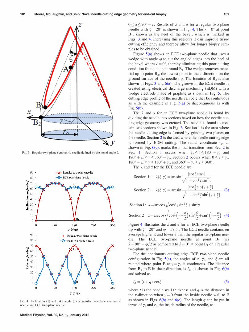
0� a� 90� � n. Results of k and a for a regular two-plane
needle with n¼ 20� is shown in Fig. 4. The k¼ 0� at point
B1, known as the heel of the bevel, which is marked in
Figs. 3 and 4. Increasing this region’s k can improve tissue
cutting efficiency and thereby allow for longer biopsy sam-
ples to be obtained.
Figure 5(a) shows an ECE two-plane needle that uses a
wedge with angle u to cut the angled edges into the heel of
the bevel where k¼ 0�, thereby eliminating this poor cutting
condition found at and around B1. The wedge removes mate-
rial up to point B2, the lowest point in the z-direction on the
ground surface of the needle tip. The location of B2 is also
shown in Figs. 3 and 6(a). The groove in the ECE needle is
created using electrical discharge machining (EDM) with a
wedge electrode made of graphite as shown in Fig. 5. The
cutting edge profile of the needle can be either be continuous
as with the example in Fig. 5(a) or discontinuous as with
Fig. 5(b).
The k and a for an ECE two-plane needle is found by
dividing the needle into sections based on how the needle cut-
ting edge geometry was created. The needle is found to con-
tain two sections shown in Fig. 6. Section 1 is the area where
the needle cutting edge is formed by grinding two planes on
the needle, Section 2 is the area where the needle cutting edge
is formed by EDM cutting. The radial coordinate ce, as
shown in Fig. 6(c), marks the initial transition from Sec. 2 to
Sec. 1. Section 1 occurs when ce� c� 180� � ce and
180� þ ce� c� 360� � ce. Section 2 occurs when 0� c� ce,
180� � ce� c� 180� þ ce, and 360� � ce� c� 360�.The k and a for the ECE needle are
Section 1 : kðn; cÞ ¼ arcsincotn sin cj jffiffiffiffiffiffiffiffiffiffiffiffiffiffiffiffiffiffiffiffiffiffiffiffiffiffiffiffiffiffi
1þ cot2 n sin2 cp
Section 2 : kðn; cÞ ¼ arcsincot /
2sin cþ p
2
� ��� ��ffiffiffiffiffiffiffiffiffiffiffiffiffiffiffiffiffiffiffiffiffiffiffiffiffiffiffiffiffiffiffiffiffiffiffiffiffiffiffiffiffi1þ cot2 /
2sin2 cþ p
2
� �q (3)
Section 1 : a¼arccos
ffiffiffiffiffiffiffiffiffiffiffiffiffiffiffiffiffiffiffiffiffiffiffiffiffiffiffiffiffiffiffiffiffiffiffifficos2csin2nþsin2c
q
Section 2 : a¼arccos
ffiffiffiffiffiffiffiffiffiffiffiffiffiffiffiffiffiffiffiffiffiffiffiffiffiffiffiffiffiffiffiffiffiffiffiffiffiffiffiffiffiffiffiffiffiffiffiffiffiffiffiffiffiffiffiffiffiffiffiffiffifficos2 cþp
2
� �sin2/
2þsin2 cþp
2
� �r(4)
Figure 4 illustrates the k and a for an ECE two-plane needle
tip with n¼ 20� and u¼ 57.5�. The ECE needle contains on
average higher k and lower a than the regular two-plane nee-
dle. The ECE two-plane needle at point B2 has
k¼ 90� �u=2 as compared to k¼ 0� at point B1 on a regular
two-plane needle.
For the continuous cutting edge ECE two-plane needle
configuration in Fig. 5(a), the angles of u, ce, and n are all
related where point E at c¼ ce is continuous. The distance
from B2 to E in the z-direction, is ln, as shown in Fig. 6(b)
and solved as
ln ¼ ðtþ qÞ cotn (5)
where t is the needle wall thickness and q is the distance in
the x-direction when y¼ 0 from the inside needle wall to E
as shown in Figs. 6(b) and 6(c). The length q can be put in
terms of ce and ri, the inside radius of the needle, as
FIG. 3. Regular two-plane symmetric needle defined by the bevel angle n.
FIG. 4. Inclination (k) and rake angle (a) of regular two-plane symmetric
needle and ECE two-plane needle.
101 Moore, McLaughlin, and Shih: Novel needle cutting edge geometry for end-cut biopsy 101
Medical Physics, Vol. 39, No. 1, January 2012

q ¼ rið1� cosceÞ (6)
The width of the top of the wedge is equal to 2c, as shown in
Figs. 5(a), 6(a), and 6(c), and c is
c ¼ ln tanðu=2Þ ¼ ri sin ce (7)
Combining Eqs. (5)–(7) gives the relationship among u, ce,
and n
cotn tanðu=2Þðtþ ri � ri cos ceÞ ¼ ri sin ce (8)
Using trigonometric identities and the quadratic equation,
this equation is solved in terms of ce as
ce ¼ 2 tan�1
1�ffiffiffiffiffiffiffiffiffiffiffiffiffiffiffiffiffiffiffiffiffiffiffiffiffiffiffiffiffiffiffiffiffiffiffiffiffiffiffiffiffiffiffiffiffiffiffiffiffiffiffiffiffiffiffiffiffiffiffiffiffiffi1� tan2
u2
� �cot2 nð Þ t2þ 2tri
r2i
� s
tanu2
� �cot nð Þ tþ 2ri
ri
0BBBB@
1CCCCA (9)
If Eq. (9) produces an imaginary solution to ce, then the cut-
ting edge must be discontinuous. In the case that the cutting
edge of Section 1 is tangent to the cutting edge of Section 2,
the square root in Eq. (9) will equal 0 with the given parame-
ters of t, ri, u, and n.
The needle cutting edge is discontinuous when point E is
discontinuous at c¼ ce, as in the example in Fig. 5(b). In this
situation, the values of u, n, and ce are independent of each
other and Eq. (9) does not apply. The geometry of a discon-
tinuous ECE two-plane needle is defined by u, n, and c.
While the geometry of a continuous ECE two-plane needle
is defined by only u and n.
III. NEEDLE INSERTION FORCE MODEL ANDS FACTOR
Moore et al.16 developed a predictive force model based
on k and a of a needle’s cutting edge to predict the force nec-
essary for a hollow needle to initially cut tissue, FN. The
model was developed by inserting 16 blades of varying kand a into bovine liver and measuring the specific force,
thereby allowing for the development of a model f(k, a), as
shown in Eq. (10), for specific force needed to cut tissue for
a cutting edge of a given k and a. Higher k lowers insertion
force while a has little affect on insertion force
f ðk; aÞ ¼ � 0:042þ 0:296kþ 0:298a� 0:255 k2
� 0:408 k a� 0:011 a2 þ 0:083 k3
þ 0:118 k2aþ 0:080 k a2 � 0:059a3 (10)
For a two-plane needle at the moment of initial tissue cut-
ting, a portion of the needle is exposed to tissue cutting as
shown in Fig. 7. The tissue contacts the needle on the lead-
ing edge of the needle tip and on the inside cutting edge, as
marked in Fig. 7(a), over a specific range marked as h in Fig.
7(b). Moore et al.16 experimentally found that this angle hchanged based on n as
h ¼ 9:2n n < 19:6�
h ¼ 180� n > 19:6�(11)
FIG. 5. (a) ECE two-plane needle with a continuous cutting edge and (b) ECE two-plane needle with a discontinuous cutting edge.
FIG. 6. ECE two-plane needle in (a) isometric view (b)
side view, and (c) top view.
102 Moore, McLaughlin, and Shih: Novel needle cutting edge geometry for end-cut biopsy 102
Medical Physics, Vol. 39, No. 1, January 2012

Moore et al.16 developed the force model shown in Eq. (12)
for a two-plane symmetric needle by integrating f(k, a)
around the inside needle tip cutting edge and calculating the
cutting force on the leading edge by knowing the leading
edge geometry for a two-plane needle is k¼ 0� and
a ¼ p2� n.
FN ¼ S
ðpþ h2
p� h2
2f ðk; aÞridcþ 2t f 0;p2� n
� �(12)
The variable S is the scale factor used to convert the straight
blade cutting to round needle insertion force using the f(k, a)
obtained in blade cutting. A round needle distributes force
over a larger area of tissue than does the flat blade, thereby
making the needle less efficient at cutting tissue than the flat
blade when no internal vacuum is applied. The S factor
properly scales the needle cutting force to the blade cutting
force. Vacuum experiments, described in the Sec. IV, show
the S factor is lower, indicating higher cutting efficiency, for
higher levels of vacuum applied.
IV. EXPERIMENTATION
IV.A. Setup for Needle insertion experiments
The overview and close-up view of the experimental
setup to perform the needle insertion experiments is shown
in Fig. 8. The experimental setup uses a Siskiyou Instrument
(Grants Pass, Oregon) 200cri linear stage, a Kistler (Winter-
thur, Switzerland) 9256A1 piezoelectric force dynamome-
ter, and a tissue holder that, via a pneumatic cylinder,
applies a static pressure of 15.5 kPa on the top of the bovine
liver tissue block to ensure consistent tissue conditions.
FIG. 8. Experimental setup for needle insertion into bovine liver.
FIG. 7. (a) Side view and (b) top view of needle tip
exposed to initial tissue cutting.
FIG. 9. Regular two-plane symmetric and ECE needles used for
experiments.
103 Moore, McLaughlin, and Shih: Novel needle cutting edge geometry for end-cut biopsy 103
Medical Physics, Vol. 39, No. 1, January 2012

Bovine liver is a very soft work-material; therefore, consist-
ent tissue holding conditions are critical to produce repeat-
able and reliable results as demonstrated by Shih et al.21 in
a study of machining elastomers, another soft work-
material. The needles were inserted at a rate of 1.5 mm=s
through 50 mm length of tissue. A vacuum pump is used to
supply a constant vacuum pressure to the inside of the nee-
dle for the experiments using the vacuum gauge pressures
of �33.9 and �67.7 kPa. After each needle insertion, the
sample was then extracted using a solid rod and biopsy
length was measured.
IV.B. Needles
A total of ten needles were manufactured as shown
in Fig. 9; five regular two-plane needles and five ECE
two-plane needles both having bevel angles, n, of 10�, 15�,20�, 25�, and 30�. The needles are 11 gauge thin wall 316
stainless steel needles (OD 3.05 mm and ID 2.54 mm). All
the ECE two-plane needles are machined with the angle
u¼ 57.5�. This angle is used because for n¼ 20�, the wedge
cutting edge will be tangent to the inside cutting edge for the
11 gauge thin wall needles. The ECE needles of n¼ 15� and
n¼ 10� are discontinuous as shown previously in Fig. 5(b).
The c value for needles n¼ 10� and 15� is 0.69 mm because
the graphite EDM milling tool used to make the needles has
a width, 2c, of 1.38 mm.
IV.C. Determination of initial tissue cutting force fromthe experiments
The force model previously described by Moore et al.16
examines the force when the tissue is initially cut (FN). The
force during needle insertion into tissue has been described by
Heverly et al.22 to occur in two distinct phases, Phase 1 and
Phase 2. Phase 1 is the initial phase where the tissue deflects
and force increases but no physical tissue cutting occurs.
Phase 2 is the second phase where tissue is cut and the force
suddenly drops or levels off. If uncut tissue is in front of the
needle after Phase 2, then Phase 1 will repeat and the process
will start over again. This cycle will continue until the needle
insertion is stopped or all the tissue is cut. The first transition
between Phase 1 and Phase 2 marks the force FN, as illus-
trated by the example force graph in Fig. 10 which shows the
force results for one of the experiments on an ECE needle of
n¼ 20�. The experimental force data from all the experiments
are examined in this way to determine FN.
IV.D. Summary of experimental procedure
In summary, this study uses five regular two-plane nee-
dles and five ECE two-plane needles (both having n¼ 10�,15�, 20�, 25�, and 30�). The ECE and regular needles are
tested at the pressures of 0, �33.9, and �67.7 kPa. Ten nee-
dle insertions are performed for each needle style and pres-
sure level upon which both insertion force and biopsy length
are measured for a total of 300 needle insertion experiments.
V. RESULTS AND ANALYSIS
Biopsy length and force results along with limiting biopsy
performance factors are discussed in Sec. V A, V B, V C,
and V D.
V.A. Biopsy length
V.A.1. Needle geometry effect
The ECE needle produces longer biopsy results than the reg-
ular needle. As illustrated in Fig. 11, the biopsy sample length
is on average 22%, 30%, and 49% longer for ECE needles
compared to that of regular needles for the internal pressures of
FIG. 10. Needle insertion into bovine liver force example of ECE needle
with n¼ 20�.
FIG. 11. Biopsy sample length comparing ECE two-plane needles to regular two-plane needles.
104 Moore, McLaughlin, and Shih: Novel needle cutting edge geometry for end-cut biopsy 104
Medical Physics, Vol. 39, No. 1, January 2012

0, �33.9, and �67.7 kPa, respectively. This demonstrates that
the ECE concept of modifying the needle to increase inclina-
tion angle on cutting edge is beneficial for end-cut biopsy. The
higher inclination angles allow for more efficient needle tip
cutting of tissue and, therefore, longer biopsy samples.
Lower bevel angles result in longer biopsy lengths for
both ECE and regular two-plane needles. The lower bevel
angles correspond to higher inclination angles that are dem-
onstrated to more efficiently cut the tissue. This observation
reflects the force model prediction that higher inclination
angles are able to cut tissue with less force.
The effect of vacuum is not easily distinguished in
Fig. 11; therefore, Fig. 12 is created by rearranging the bi-
opsy length data to compare the three vacuum levels.
V.A.2. Vacuum effect
For regular two-plane needles shown in Fig. 12(a), the use
of vacuum improves biopsy length for n¼ 10� and 15� but
shows no effect for n¼ 20�, 25�, and 30�. Previously Moore
et al.16 showed that higher k cuts tissue with lower insertion
force making the cutting edge more efficient at cutting tissue.
The low inclination angles in the regular needles of n¼ 20�,25�, and 30� make them inefficient at cutting tissue. The vac-
uum is only beneficial to biopsy length if the needle tip can
efficiently cut the tissue. If the needle tip can efficiently cut
tissue, then the tissue sample that enters the needle can be
pulled into the needle by the vacuum force which acts to
overcome the internal wall needle friction as shown in Fig.
13. If the needle is unable to effectively cut tissue, then the
tissue sample does not effectively enter the needle preventing
the vacuum force from benefiting the biopsy yield.
For ECE needles, the vacuum level of �67.7 kPa produces
on average biopsy lengths that are 41, 31, 29, 45, and 42%
longer compared to no vacuum for n¼ 10�, 15�, 20�, 25�,and 30�, respectively, as illustrated in Fig. 12(b). The ECE
needle tip’s high inclination angle makes it effective at cut-
ting the tissue and the vacuum allows the needle to overcome
the internal tissue friction shown in Fig. 13; thereby, leading
to longer biopsy samples for vacuum assisted ECE needles.
V.B. Biopsy force
V.B.1. Needle geometry effect
The ECE needle produces lower needle insertion forces
than regular needles for n¼ 20�, 25�, and 30� as shown in
Fig. 14. The initial insertion force is on average 20%, 9%, and
5% higher for regular compared to ECE two-plane needles for
the internal needle pressures of 0, �33.9, and �67.7 kPa,
respectively, on the needles of n¼ 20�, 25�, and 30�. Cutting
force differences between ECE and regular needles are less
noticeable at higher vacuum levels because increased vacuum
lowers cutting force on all needles, thereby making differen-
ces in performances less pronounced.
The needles of n¼ 10� and n¼ 15� show little change
because the ECE needle geometry differs from the regular
two-plane needle only at the far back of the needle tip and the
initial tissue cutting occurs at the front of the needle tip when
n¼ 10� and 15�. This lower force for higher inclination angles
corresponds to previous findings by Moore et al.16
For both ECE and regular two-plane needles, lower bevel
angles result in lower biopsy insertion forces. Again demon-
strating that less force is required to cut tissue when using
needles containing higher inclination angles.
V.B.2. Vacuum effect
Vacuum lowers the average insertion force for both regu-
lar and ECE two-plane needles of n¼ 15�, 20�, 25�, and 30�
as illustrated in Figs. 15(a) and 15(b), respectively. When
vacuum is used the vacuum force helps to apply the force
necessary to cut the tissue which leads to lower insertion
forces. The vacuum also aids in overcoming the internal nee-
dle friction as discussed in Sec. V A 2.
For the needles of n¼ 10�, the vacuum level appears to
have little effect on the insertion force. This happens because
the initial tissue cutting occurs at the very front of the needle
FIG. 12. Biopsy sample length comparing pressure
effect for (a) regular and (b) ECE two-plane needles.
FIG. 13. Internal wall friction force repels the motion of the incoming tissue
while the vacuum force helps to pull the sample into the needle.
105 Moore, McLaughlin, and Shih: Novel needle cutting edge geometry for end-cut biopsy 105
Medical Physics, Vol. 39, No. 1, January 2012

n¼ 10�. In this configuration, the vacuum is unable to apply
a vacuum force on the tissue because mostly air is being
pulled into the needle.
V.C.3. S-factor variation for vacuum effect
The S factor decreases at higher vacuum levels for both
ECE and regular needles showing that vacuum improves cut-
ting efficiency. The S factor in Eq. (12) is determined using
a least squares fit to the force data for the regular two-plane
needles and ECE needles, for all the three tested levels of in-
ternal needle pressure as shown in Fig. 16. Figure 17 shows
that the S factor for both types of needles decreases at lower
pressures. This indicates higher cutting efficiency is obtained
when lower vacuum pressure is applied to the inside of the
needles.
V.C. Comparing biopsy length to biopsy force
Needles of higher inclination angle that produce lower
insertion forces also produce on average longer biopsy sam-
ple lengths. Figures 18(a)–18(c) shows the relationship
between needle insertion forces and biopsy length for inter-
nal needle pressures of 0, �33.9, and �67.7 kPa, respec-
tively. Least squares fit linear lines are illustrated for both
ECE and regular needles. It is shown that for both ECE and
regular needles lower needle insertion forces coincide with
longer biopsy lengths as shown with least squares fit linear
lines all having negative slopes. Lower insertion forces are
an indication of more efficient tissue cutting. More efficient
tissue cutting leads to longer biopsy sample lengths.
Figure 18 also shows the R2 values for the linear least
squares best fit lines. Higher levels of vacuum lead to higher
R2 values which indicate a more linear relationship. This
improved linearity is a direct result of the vacuum force
overcoming the internal needle friction which hinders longer
biopsy lengths from being obtained. Figure 18(a) shows that
for the internal needle pressure of 0 kPa both ECE and
regular needles lower force corresponds to little improve-
ment in biopsy length when n¼ 10� and 20�, the needles that
produce the two lowest needle insertion forces. However, for
the internal needle pressure of �33.9 kPa [Fig. 18(b)] and
�67.7 kPa [Fig. 18(c)], lower forces correspond to signifi-
cantly longer biopsy lengths even for the highest biopsy
lengths found when n¼ 10� and 20�.Higher vacuum allows for a steeper slope in force to bi-
opsy length results as shown in Fig. 18. This is a result of
vacuum creating both lower needle insertion forces and lon-
ger biopsy lengths. The slope of both ECE and regular nee-
dles are very similar for the vacuum pressures of �33.9 kPa
and �67.7 kPa. This occurs because internal needle friction
FIG. 14. Needle insertion force comparing ECE two-plane needles to regular two-plane needles.
FIG. 15. Needle insertion force comparing pressure effect for (a) regular and (b) ECE two-plane needles.
106 Moore, McLaughlin, and Shih: Novel needle cutting edge geometry for end-cut biopsy 106
Medical Physics, Vol. 39, No. 1, January 2012

is not hindering the biopsy length acquisition; therefore, the
force of initial insertion is directly related to biopsy length.
V.D. Limiting biopsy performance factors
The performance of the ECE needle is limited by the nee-
dle tip length. Results showed that lower values of nimproved biopsy performance but the needle tip length,
which equals ri=tann, increases greatly at lower n values.
Too long of a needle tip length will cause the needle tip to
become weaker which puts the needle at risk for bending or
breaking inside the patient.
Results showed that higher vacuum can allow for longer
biopsy lengths. However, too high of a vacuum may cause
the tissue sample to be pulled into the vacuum hose making
it difficult to be retrieved. High vacuum levels may create
fragmented biopsy samples which cause less accurate
diagnosis.2
FIG. 16. Force model prediction with given S factors for regular two-plane and ECE needles.
FIG. 17. The effect of needle vacuum pressure on S factor.
107 Moore, McLaughlin, and Shih: Novel needle cutting edge geometry for end-cut biopsy 107
Medical Physics, Vol. 39, No. 1, January 2012

VI. CONCLUSIONS
This study demonstrated that needles of higher inclination
angle that produce lower insertion forces also produce on av-
erage longer biopsy sample lengths. The novel ECE needle
tip design was proposed and experimentally determined to
outperform the regular two-plane symmetric needle by on
average yielding longer biopsy samples. Biopsy sample
length is on average 22%, 30%, and 49% longer for ECE
needle compared to that of regular needle for the internal
pressures of 0, �33.9, and �67.7 kPa, respectively. The use
of vacuum further improved the ECE needle tips biopsy
sample length. For ECE needles the vacuum level of �67.7
kPa produces on average biopsy lengths that are 41, 31, 29,
45, and 42% longer compared to no vacuum for n¼ 10�,15�, 20�, 25�, and 30�, respectively.
The force results showed the ECE needle could be inserted
with less initial insertion force than the two-plane needle for
needles where the needle tip was fully contacting the tissue
upon insertion. Vacuum was also showed to help lower inser-
tion forces. The S factor of the needle force model was shown
to decrease upon increasing the vacuum, indicating a more ef-
ficient tissue cutting can take place with the use of vacuum.
Future work will focus on optimizing an ECE needle and vac-
uum level that is safe for patient use and does not lead to dam-
aged or difficult to retrieve biopsy samples.
ACKNOWLEDGMENTS
This research work is sponsored by the National Science
Foundation (NSF) Award CMMI#0825795, National Natural
Science Foundation of China (Award No. 50775119), and
supported by the University of Michigan Radiation Oncol-
ogy Department.
a)Author to whom correspondence should be addressed. Electronic mail:
[email protected]. Fink, G. Hutarew, A. Pytel, and N. Schmeller, “Prostate biopsy out-
come using 29 mm cutting length,” Urol. Int., 75(3), 209–212 (2005).2K. Iczkowski, G. Casella, R. Seppala, G. Jones, B. Mishler, J. Qian, and
D. Bostwick, “Needle core length in sextant biopsy influences prostate
cancer detection rate,” Urology, 59(5), 698–703 (2002).3G. Ubhayakar, W. Li, C. Corbishley, and U. Patel, “Improving glandular
coverage during prostate biopsy using a long-core needle: Technical per-
formance of an end-cutting needle,” BJU Int. 89(1), 40–43 (2002).4C. D. Lehman and T. Aikawa, “MR-guided vacuum-assisted breast bi-
opsy: Accuracy of targeting and success in sampling in a phantom model,”
Radiology 232(3), 911–914 (2004).
5T. K. Podder, D. P. Clark, J. Sherman, D. Fuller, E. Messing, D. Rubens,
J. Strang, R. Brasacchio, L. Liao, W. S. Ng, and Y. Yu, “in vivo motion
and force measurement of surgical needle intervention during prostate
brachytherapy,” Med. Phys. 33, 2915–2922 (2006).6B. Maurin, L. Barbe, B. Bayle, P. Zanne, J. Gangloff, M. de Mathelin, A.
Gangi, L. Soler, and A. Forgione, “In vivo study of forces during needle
insertions,” edited by T. M. Buzug and T. C. Lueth, Perspectives in
image-guided surgery (World Scientific Pub Co, Singapore, 2004), pp.
415–422.7T. K. Podder, D. P. Clark, J. Sherman, D. Fuller, E. Messing, D. J. Rubens,
J. G. Strang, Y. D. Zhang, W. O’Dell, W. S. Ng, and Y. Yu, “Effects of tip
geometry of surgical needles: an assessment of force and deflection,” 3rdEuropean Medical and Biological Engineering Conference, (Prague,
Czech Republic, 2005).8M. O’Leary, C. Simone, T. Wahio, K. Yoshinaka, and A. Okamura,
“Robotic needle insertion: effects of friction and needle geometry,” in the
2003 IEEE International Conference on Robotics and Automation (Taipei,
Taiwan, 2003), pp. 1774–1780.9H. Kataoka, T. Washio, M. Audette, and K. Mizuhara, “A model for rela-
tions between needle deflection, force, and thickness on needle pene-
tration,” in the Proceedings of the 4th International Conference onMedical Image Computing and Computer-Assisted Intervention (Utrecht,
The Netherlands, 2001), pp. 966–974.10A. M. Okamura, C. Simone, and M. O’Leary, “Force modeling for needle
insertion into soft tissue,” IEEE Trans. Biomed. Eng. 51, 1707–1716 (2004).11R. Webster, J. Kim, N. Cowan, G. Chirikjian, and A. Okamura,
“Nonholonomic modeling of needle steering,” Int. J. Robot. Res. 25(5–6),
509–525 (2006).12J. Moore, Q. Zhang, C. McGill, P. McLaughlin, H. Zheng, and A. Shih,
“Cutting edge rake and inclination angles modeling for plane needles,”
J. Manuf. Sci. Eng. 132(5), 051005 (2010).13J. Moore, Q. Zhang, C. McGill, H. Zheng, P. McLaughlin, and A. Shih,
“Modeling cutting edge geometry for plane and curved needle tips,” Proc.
Inst. Mech. Eng., Part B (accepted).14J. Moore, C. McGill, Q. Zhang, P. McLaughlin, H. Zheng, and A. Shih,
“Blade oblique cutting of tissue for investigation of biopsy needle
insertion,” Trans. NAMRI=SME 37, 49–56 (2009).15J. Moore and A. Shih, “Tissue oblique cutting flow angle and needle inser-
tion contact length,” Trans. NAMRI=SME 38, 711–718 (2010).16J. Moore, K. Malukhin, A. Shih, and K. Ehmann, “Hollow needle tissue
insertion force model,” CIRP Ann. – Manuf. Technol. 60, 157–160
(2011).17T. Kucklick, The Medical Device R&D Handbook (Taylor & Francis,
Boca Raton, 2006).18R. L. Huber, “Hypodermic needle,” U.S, patent 2,409,979 (22 October
1946).19Chauncy F. Ross, “Hypodermic needle,” U.S. patent 6,702,790 (9 March
2004).20Joseph F. Gravlee, Jr., “Hypodermic needle,” U.S. patent 5,733,266 (31
March 1998).21A. Shih, M. Lewis, and J. Strenkowski, “End milling of elastomers—
Fixture design and tool effectiveness for material removal,” J. Manuf. Sci.
Eng. 126,115–123 (2004).22M. Heverly, P. Dupont, and J. Triedman, “Trajectory optimization for
dynamic needle insertion,” International Conference on Robotics andAutomation (Barcelona, Spain, 2005), pp. 1658–1663.
FIG. 18. Needle insertion force compared to biopsy length with least squares best fit lines for needle pressures of (a) 0 kPa, (b) �33.9 kPa, and (c) �67.7 kPa.
108 Moore, McLaughlin, and Shih: Novel needle cutting edge geometry for end-cut biopsy 108
Medical Physics, Vol. 39, No. 1, January 2012


![Impact of a Modified Needle Tip Geometry on Penetration ... · Multiple factors impact subcutaneous insulin injection pain. Injection devices [e.g., syringe or pen needle (PN)] affect](https://img.dokumen.tips/doc/110x75/5ea621ddc0be5f67aa36cdbb/impact-of-a-modified-needle-tip-geometry-on-penetration-multiple-factors-impact.jpg)