Embed Size (px)
Citation preview
International Journal of Reviews in Computing © 2009 IJRIC. All rights reserved. IJRIC
www.ijric.org E-ISSN: 2076-3336
25
NOVEL DEVELOPMENT OF A FUZZY CONTROL SCHEME WITH UPFC’s FOR DAMPING OF OSCILLATIONS IN
MULTI-MACHINE POWER SYSTEMS
1 DAKKA OBULESU, 2Dr. S.F. KODAD, 3Dr. B.V. SANKAR RAM
1 Research Scholar, EEE Dept., JNTU, Hyderabad-85, Andhra Pradesh, India, Associate Professor, MITS, Madanapalli, Chittor Dist, AP, India.
Phone : +91 09441078630, Email : [email protected], [email protected] 2 Professor & HOD, Dept. of EEE, Aurora Engg College, Bhongir-508116.
Phone: +91 09866666660, Email : [email protected] 3 Professor, Dept. of EEE, JNTUCE, Kukatpally, Hydarabad-85.
Phone: +91 09849303342, Email : [email protected]
ABSTRACT
This paper presents a novel development of a fuzzy logic controlled power system using UPFCs to damp the oscillations in a FACTS based integrated multi-machine power system consisting of 3 generators, 3 transformers, 9 buses, 4 loads & 2 UPFCs. Oscillations in power systems have to be taken a serious note of when the fault takes place in any part of the system, else this might lead to the instability mode & shutting down of the power system. UPFC based POD controllers can be used to suppress the oscillations upon the occurrence of a fault at the generator side or near the bus side. In order to improve the dynamic performance of the multi-machine power system, the behavior of the UPFC based POD controller should be coordinated, otherwise the power system performance might be deteriorated. In order to keep the advantages of the existing POD controller and to improve the UPFC-POD performance, a hybrid fuzzy coordination based controller can be used ahead of a UPFC based POD controller to increase the system dynamical performance & to coordinate the UPFC-POD combination. This paper depicts about this hybrid combination of a fuzzy with a UPFC & POD control strategy to damp the electro-mechanical oscillations. The amplification part of the conventional controller is modified by the fuzzy coordination controller. Simulink models are developed with & without the hybrid controller. The 3 phase to ground symmetrical fault is made to occur near the first generator for 200 ms. Simulations are performed with & without the controller. The digital simulation results show the effectiveness of the method presented in this paper.
Keywords : UPFC, POD, Fuzzy logic, Coordination, Controller, Oscillations, Damping, Stability, Simulink, State space model.
1. INTRODUCTION Applications of ANN to power systems are a growing area of interest. In the modern day power system stability, operation & control (PSOC), FACTS (Flexible AC Transmission Systems) plays a very important role. Usage of FACTS in the power systems not only enhances the dynamic performance, but also increases the stability of the power systems, enhances the controllability & increases its power transfer capability. Some of the devices used in the control of FACTS are the SVC, TCSC, STATCOM, UPFC, and the IPFC. The FACTS controllers utilize power electronics based technology and can provide dynamic control on line power flows, bus voltages, line impedance & phase
angles. One of the controllers being used in the work presented in this paper is the UPFC based fuzzy coordination scheme for the damping of power system oscillations [1].
The FACTS initiative was originally launched in 1980’s to solve the emerging problems faced due to restrictions on transmission line construction, and to facilitate growing power export / import and wheeling transactions among utilities. The two basic objectives behind the development of FACTS technology; is to increase power transfer capability of transmission systems, and to keep power flow over designated routes, significantly increase the utilization of existing (and new) transmission assets, and play a major role in facilitating

International Journal of Reviews in Computing © 2009 IJRIC. All rights reserved. IJRIC
www.ijric.org E-ISSN: 2076-3336
26
contractual power flow in electricity markets with minimal requirements for new transmission lines.
According to IEEE, FACTS - which is the abbreviation of Flexible AC Transmission Systems, is defined as “alternating current transmission systems incorporating power electronics based and other static controllers to enhance controllability and power transfer capability”. Dynamic reactive power compensation and damping power system oscillations can also be achieved using FACTS controllers. Injecting the series voltage phasor, with desirable voltage magnitude and phase angle in a line can provide a powerful means of precisely controlling the active and reactive power flows, by which system stability can be improved, system reliability can be enhanced while operating and transmission investment cost can be reduced.
It is possible to vary the impedance of specific transmission line to force power flow along a desired “contract path” in the emerging power systems, and to regulate the unwanted loop power flows and parallel power flows in the interconnected system. The FACTS controllers have been broadly developed on two different principles, one that alters the line series reactance or bus shunt reactance or voltage phase difference across a line and utilizes conventional thyristor switches for control. In general, FACTS controllers can be divided into four categories based on their connection in the network, viz., series, shunt, combined series-series, and combined series-shunt. In our work, we have used the series-shunt combination [2].
FACTS devices have shown very promising results when used to improve the power system steady state performance. In addition, because of the extremely fast control action associated with FACTS-device operations, they have been very promising candidates for utilization in power system damping enhancement. The first generation FACTS devices include SVC, TCPS, and TCSC. It has been found that SVCs can be effective in damping power system oscillations if a supplementary feedback signal is applied [11-12]. Compared with other FACTS devices, little attention has been paid to TCPS modeling and control. Based on the equal area criterion, the TCPS control problem has also investigated using linear control techniques [13-15].
Many research efforts have been devoted to the control of TCSC. Chen et. al. designed a state feedback TCSC controller based on the pole placement technique [16]. Other TCSC optimal and nonlinear control schemes proposed in the literature
[17-19]. A unified power flow controller (UPFC) is the most promising device in the FACTS concept. Several trials have been reported in the literature to model a UPFC for steady-state and transient studies. Based on Nabavi–Iravani model [20], Wang developed two UPFC models [21-23] which have been linearized and incorporated into the Heffron-Phillips model [3].
FACTS devices enhance the stability of the power system with its fast control characteristics and continuous compensating capability. The controlling of the power flow and increasing the transmission capacity of the existing transmission lines are the two main objectives of FACTS technology [25]. Thus, the utilization of the existing power system comes into optimal condition and the controllability of the power system is increased with these objectives. Gyugyi proposed the Unified Power Flow Controller which is the new type generation of FACTS devices in the year 1991 [26]. Unified Power Flow Controller (UPFC), being one the member of the FACTS device thus emerged as one of the effective controllers for controlling and optimization of the power flow in the electrical power transmission systems [7]. This device was formed due to the combination of the two other FACTS devices, namely Static Synchronous Compensator (STATCOM) and the Static Synchronous Series Compensator (SSSC). These are connected to each other by a common DC link, which is a typical a storage capacitor. The all parameters of the power transmission line (impedance, voltage and phase angle) can be control simultaneously by UPFC [28]. In addition, it can perform the control function of the transmission line real / reactive power flow, UPFC bus voltage and the shunt-reactive-power flow control [29].
The control mechanism and the controller have an important effect on the performance of UPFC. In the literature, several control mechanisms are used in UPFC models. A novel fuzzy inference system described in matrix form was proposed and used to improve the dynamic control of real and reactive power [30]. Two fuzzy logic controllers based on Mamdani type fuzzy logic were used. In our work considered, we have used the Mamdani type fuzzy logic scheme for the control purposes [3].
The selection of suitable location for UPFC was studied and composite-criteria based fuzzy logic was used to evaluate the network contingency ranking [31]. The power-feedback control scheme is used in the control mechanism of UPFC [32]. The power fluctuation is damped readily and the

International Journal of Reviews in Computing © 2009 IJRIC. All rights reserved. IJRIC
www.ijric.org E-ISSN: 2076-3336
27
value of reactive power is minimized as possible by using several time constants. However, there is no change in the value of the real power. The control method of variable interval-fuzzy-mutual is used in the control mechanism of UPFC [33]. The performance of UPFCs is observed by using three different controllers comparisons in [34-35].
In recent years, the fast progress in the field of power electronics has opened new opportunities for the power industry via utilization of the controllable Flexible AC Transmission System devices like Unified Power Flow Controller which offer an alternative means to mitigate power system oscillations [5]. Oscillation Stability analysis and control has been an important subject in power system research and applications. The deregulation and competitive environment in the contemporary power networks [1, 2] will imply a new scenario in terms of load and power flow condition and so causing problems of line transmission capacity. But, nowadays, some problems exist like power system oscillation stability & refers to the damping of electromechanical oscillations occurring in power systems with oscillation frequency in the range of 0.2 Hz. to 2 Hz. These low-frequency oscillations are the consequence of the development of interconnection of large power systems. A low frequency oscillation in a power system constrains the capability of power transmission, threatens system security and damages the efficient operation of the power system [4].
Damping of electromechanical oscillations between interconnected machines in a integrated power system is always necessary for a secured system operation. A FACTS controller always increases the transmission capability and the stability. Researchers have developed a number of methods for damping of power system oscillations using FACTS devices. However, majority of them are confined to single machine infinite bus systems. Very few researchers have worked on multi-machine control of FACTS systems. Of course, this yields satisfactory results [6]. But, excellent results can be obtained using the fuzzy logic concepts, neural network concepts & the genetic algorithms. This has been showed by few researchers in their papers [10], [36]. In this paper, we make a modest attempt to simulate a fuzzy logic control scheme with a UPFC for a FACTS power system to dampen the power system oscillations [7].
The fuzzy logic control technique has been an active research topic in automation and control theory since the work of Mamdani proposed in
1974 based on the fuzzy sets theory of Zadeh proposed in 1965 to deal with the system control problems which are not easy to be modeled [36]. The concept of FLC is to utilize the qualitative knowledge of a system to design a practical controller. For a process control system, a fuzzy control algorithm embeds the intuition and experience of an operator designer and researcher. The control doesn’t need accurate mathematical model of a plant, and therefore, it suits well to a process where the systems with uncertain or complex dynamics. Of course, fuzzy control algorithm can be developed by adaptation based on learning and fuzzy model of the plant [14]. The fuzzy control is basically non-linear and adaptive in nature, giving robust performance under parameter variation and load disturbance effect [8].
In general, a fuzzy control algorithm consists of a set of heuristic decision rules and can be regarded as an adaptive and non-mathematical control algorithm based on a linguistic process, in contrast to a conventional feedback control algorithm [3], [4]. Controlled Series Compensation for Improving Stability of Multi-Machine Power Systems in [17]. Fuzzy control using linguistic information possesses several advantages such as robustness, model-free, universal approximation theorem and rules-based algorithm [5], [6]. Recent literature has explored the potentials of fuzzy control for machine drive application [7], [8]. It has been shown that a properly designed direct fuzzy controller can out-perform conventional proportional integral derivative (PID) controllers [8]. Note that fuzzy logic controllers are nothing but rule-based controllers in which a set of rules representing a control decision mechanism to adjust the effect of certain cases coming from power system is considered. Further, these FLCs do not require a mathematical model of the system & can cover a wide range of operating conditions with much robustness inherency. FLCs combined with UPFC can definitely reduce the POD in multi-machine systems [9].
In an interconnected power system, the synchronous generators should rotate at the same speed and power flows over tie-lines should remain constant under normal operating conditions. However, low frequency electromechanical oscillations may occur when a disturbance is applied to the power system. These oscillations can be observed in most power system variables like bus voltage, line current, generator rate and power. Power system oscillations were first observed as soon as synchronous generators were
International Journal of Reviews in Computing © 2009 IJRIC. All rights reserved. IJRIC
www.ijric.org E-ISSN: 2076-3336
28
interconnected to provide more generation capacity and more reliability to a power system [10].
Originally, the fairly closely connected generators were observed to swing against each other at frequencies of around 1 – 2 Hz. Damper windings on the generator’s rotor were used to prevent the amplitude of oscillations from increasing. After fast excitation systems were introduced to prevent the generators from loosing synchronism following a system is fault, it was noticed that this kind of excitation system always tends to reduce the damping of the system oscillations. Advanced tuning of POD controllers for EPS using FACTS to damp the oscillations was presented by Korba et.al. [37].
The organization of the paper is as follows. Firstly, a brief introduction to the FACTS, its evolutions, applications, the UPFC controller & the fuzzy logic controller was presented in the previous paragraphs. Section 2 presents the mathematical modeling of the multi-machine system along with the parameters. In section 3, the control strategy, the design of the controller is presented. Section 4 presents the development of the Simulink model for the damping of the power system oscillations. Simulation results are presented in section 5. Conclusions are finally presented at the end in section 6. This is followed by the acronyms & the references.
2. MODELING OF THE 3-MACHINE, 9-BUS INTEGRATED POWER SYSTEM
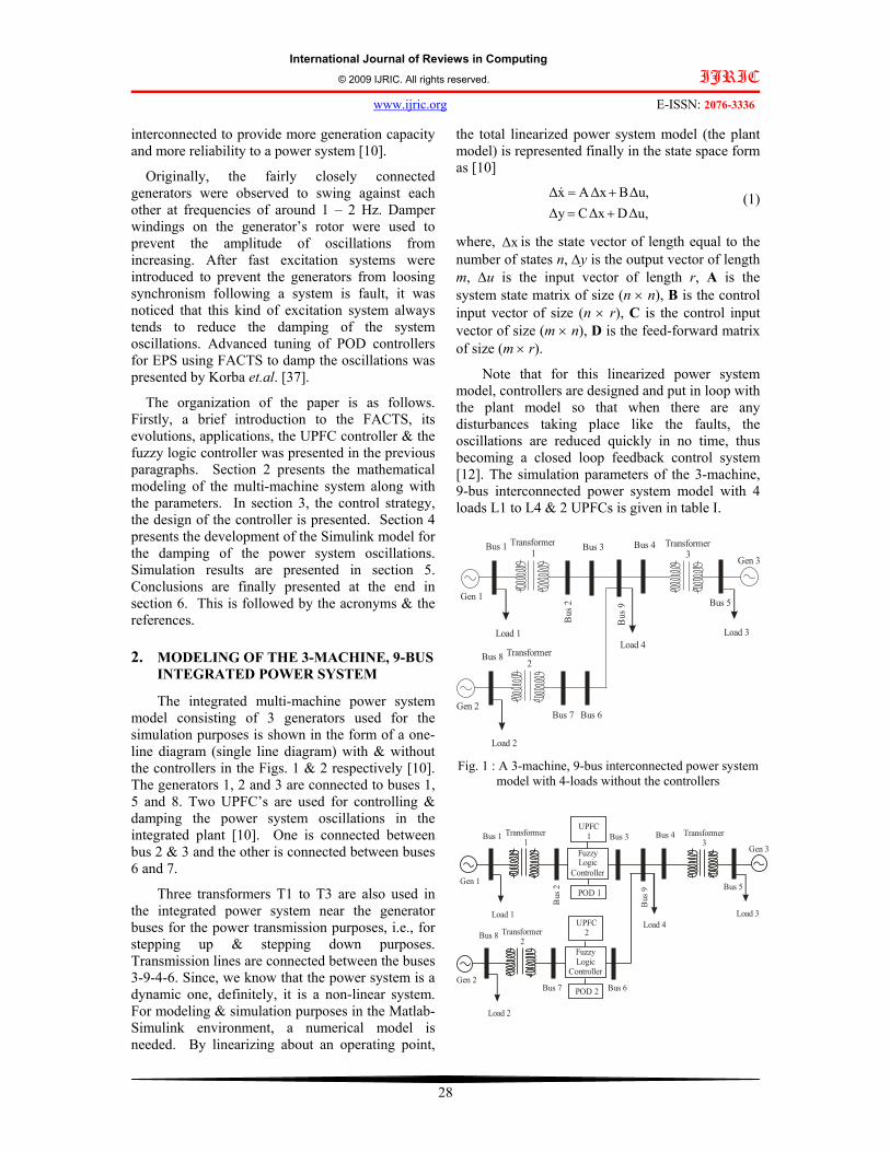
The integrated multi-machine power system model consisting of 3 generators used for the simulation purposes is shown in the form of a one-line diagram (single line diagram) with & without the controllers in the Figs. 1 & 2 respectively [10]. The generators 1, 2 and 3 are connected to buses 1, 5 and 8. Two UPFC’s are used for controlling & damping the power system oscillations in the integrated plant [10]. One is connected between bus 2 & 3 and the other is connected between buses 6 and 7.
Three transformers T1 to T3 are also used in the integrated power system near the generator buses for the power transmission purposes, i.e., for stepping up & stepping down purposes. Transmission lines are connected between the buses 3-9-4-6. Since, we know that the power system is a dynamic one, definitely, it is a non-linear system. For modeling & simulation purposes in the Matlab-Simulink environment, a numerical model is needed. By linearizing about an operating point,
the total linearized power system model (the plant model) is represented finally in the state space form as [10]
∆u,D∆xC∆y∆u,B∆xAx∆
+=+=& (1)
where, ∆x is the state vector of length equal to the number of states n, ∆y is the output vector of length m, ∆u is the input vector of length r, A is the system state matrix of size (n × n), B is the control input vector of size (n × r), C is the control input vector of size (m × n), D is the feed-forward matrix of size (m × r).
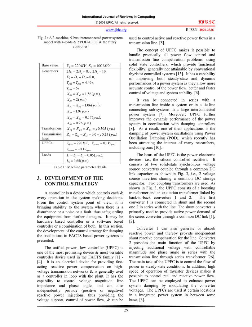
Note that for this linearized power system model, controllers are designed and put in loop with the plant model so that when there are any disturbances taking place like the faults, the oscillations are reduced quickly in no time, thus becoming a closed loop feedback control system [12]. The simulation parameters of the 3-machine, 9-bus interconnected power system model with 4 loads L1 to L4 & 2 UPFCs is given in table I.
Gen 1
Bus 1 Transformer 1B
us 2
Bus 3
Load 1B
us 9
Bus 4 Transformer 3 Gen 3
Bus 5
Load 3
Gen 2
Bus 8 Transformer 2
Bus 7 Bus 6
Load 2
Load 4
Fig. 1 : A 3-machine, 9-bus interconnected power system model with 4-loads without the controllers
Gen 1
Bus 1 Transformer 1
Bus
2
FuzzyLogic
Controller
Bus 3
Load 1
Bus
9
Bus 4 Transformer 3
Gen 3
Bus 5
Load 3
Gen 2
Bus 8 Transformer 2
Bus 7 Bus 6
Load 2
Load 4
UPFC1
POD 1
FuzzyLogic
Controller
UPFC2
POD 2
International Journal of Reviews in Computing © 2009 IJRIC. All rights reserved. IJRIC
www.ijric.org E-ISSN: 2076-3336
29
Fig. 2 : A 3-machine, 9-bus interconnected power system model with 4-loads & 2 POD-UPFC & the fuzzy
controller
Base value MVASKVV BB 100,220 ==Generators
.).(25.0.),.(17.0
.).(9.1.),.(06.1
.).(2.),.(56.1
6,49.4,0.0
102,822
3
21
3
21
3
21
03
0201
321
321
upXupXX
upXupXX
upXupXX
sTsTT
DDDHsHH
d
dd
q
d
dd
d
dd
===
=
===
===
=====
===
Transformers .).(305.0321 upjXXX TTT ===Transmission lines
.).(25.00.0321 upjZZZ lll +===
UPFCs
Operse
OperseOper
VVVVKVV
1.0,1.0,220
min
max
−=
==
Loads .).(65.0
.),.(05.0
4
321
upLupLLL
====
Table I : Machine parameter details
3. DEVELOPMENT OF THE CONTROL STRATEGY
A controller is a device which controls each & every operation in the system making decisions. From the control system point of view, it is bringing stability to the system when there is a disturbance or a noise or a fault, thus safeguarding the equipment from further damages. It may be hardware based controller or a software based controller or a combination of both. In this section, the development of the control strategy for damping the oscillations in FACTS based power systems is presented.
The unified power flow controller (UPFC) is one of the most promising device & most versatile controller device used in the FACTS family [1] - [4]. It is an electrical device for providing fast-acting reactive power compensation on high-voltage transmission networks & is generally used as a controller in loop with the plant. It has the capability to control voltage magnitude, line impedance and phase angle, and can also independently provide (positive or negative) reactive power injections, thus providing the voltage support, control of power flow, & can be
used to control active and reactive power flows in a transmission line. [5].
The concept of UPFC makes it possible to handle practically all power flow control and transmission line compensation problems, using solid state controllers, which provide functional flexibility, generally not attainable by conventional thyristor controlled systems [13]. It has a capability of improving both steady-state and dynamic performances of a power system as they allow more accurate control of the power flow, better and faster control of voltage and system stability. [6].
It can be connected in series with a transmission line inside a system or in a tie-line connecting sub-systems in a large interconnected power system [7]. Moreover, UPFC further improves the dynamic performance of the power system in coordination with damping controllers [8]. As a result, one of their applications is the damping of power system oscillations using Power Oscillation Damping (POD), which recently has been attracting the interest of many researchers, including ours [10].
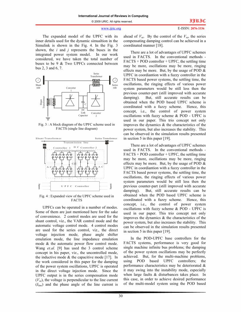
The heart of the UPFC is the power electronic devices, i.e., the silicon controlled rectifiers. It consists of two solid-state synchronous voltage source converters coupled through a common DC link capacitor as shown in Fig. 3, i.e., 2 voltage source inverters sharing a common DC storage capacitor. Two coupling transformers are used. As shown in Fig. 3, the UPFC consists of a boosting transformer and an excitation transformer linked by back-to-back converters 1 and 2. The first converter 1 is connected in shunt and the second one 2 in series with the line. The shunt converter is primarily used to provide active power demand of the series converter through a common DC link [1], [2].
Converter 1 can also generate or absorb reactive power and thereby provide independent shunt reactive compensation for the line. Converter 2 provides the main function of the UPFC by injecting additional voltage with controllable magnitude and phase angle in series with the transmission line through series transformer [26]. The main task of the UPFC is to control the flow of power in steady-state conditions. In addition, high speed of operation of thyristor devices makes it possible to control real and reactive power flow. The UPFC can be employed to enhance power system damping by modulating the converter voltages. The UPFCs are used at certain locations in a integrated power system in between some buses [3].
International Journal of Reviews in Computing © 2009 IJRIC. All rights reserved. IJRIC
www.ijric.org E-ISSN: 2076-3336
30
The expanded model of the UPFC with its inner details used for the dynamic simualtion in the Simulink is shown in the Fig. 4. In the Fig. 3 shown, the i and j represents the buses in the integrated power system model. In our work considered, we have taken the total number of buses to be 9 & Two UPFCs connected between bus 2, 3 and 6, 7.
i j
SeriesTransformer
Shun
tTr
ansf
orm
er
Converter1
Converter2
Shuntside
Seriesside
DC Link
Capacitor
C
Fig. 3 : A block diagram of the UPFC scheme used in FACTS (single line diagram)
C
Series TransformerS hun t Transfo rm er
U P F C C on tro lle r
Inpu
ts
Inputs
C on tro lle r 1 C on tro lle r 2
A C A C
D C
Transm ission line
Fig. 4 : Expanded view of the UPFC scheme used in FACTS
UPFCs can be operated in a number of modes. Some of them are just mentioned here for the sake of convenience. 2 control modes are used for the shunt control, viz., the VAR control mode and the automatic voltage control mode. 4 control modes are used for the series control, viz., the direct voltage injection mode, phase angle shifter emulation mode, the line impedance emulation mode & the automatic power flow control mode. Wang et.al. [9] has used the 3 control scheme concept in his paper, viz., the uncontrolled mode, the inductive mode & the capacitive mode [17]. In the work considered in this paper for the damping of the power system oscillations, UPFC is operated in the direct voltage injection mode. Since the UPFC output is in the series compensation mode (Vse), the voltage is perpendicular to the line current (Iline) and the phase angle of the line current is
ahead of Vse. By the control of the Vse, the series compensating damping control can be achieved in a coordinated manner [18].
There are a lot of advantages of UPFC schemes used in FACTS. In the conventional methods - FACTS + POD controller + UPFC, the settling time may be more, oscillations may be more, ringing effects may be more. But, by the usage of POD & UPFC in coordiantion with a fuzzy controller in the FACTS based power systems, the settling time, the oscillations, the ringing effects of various power system parameters would be still less then the previous counter-part (still improved with accurate damping). But, still accurate results can be obtained when the POD based UPFC scheme is coordinated with a fuzzy scheme. Hence, this concept, i.e., the control of power system oscillations with fuzzy scheme & POD - UPFC is used in our paper. This trio concept not only improves the dynamics & the characteristics of the power system, but also increases the stability. This can be observed in the simulation results presented in section 5 in this paper [19].
There are a lot of advantages of UPFC schemes used in FACTS. In the conventional methods - FACTS + POD controller + UPFC, the settling time may be more, oscillations may be more, ringing effects may be more. But, by the usage of POD & UPFC in coordiantion with a fuzzy controller in the FACTS based power systems, the settling time, the oscillations, the ringing effects of various power system parameters would be still less then the previous counter-part (still improved with accurate damping). But, still accurate results can be obtained when the POD based UPFC scheme is coordinated with a fuzzy scheme. Hence, this concept, i.e., the control of power system oscillations with fuzzy scheme & POD - UPFC is used in our paper. This trio concept not only improves the dynamics & the characteristics of the power system, but also increases the stability. This can be observed in the simulation results presented in section 5 in this paper [19].
In the POD-UPFC base controllers for the FACTS systems, performance is very good for single machine infinite bus problems; the damping of the power system oscillations may be perfectly achieved. But, for the multi-machine problems, using POD based UPFC controllers; the performance characteristics may be deteriorated & it may swing into the instability mode, especially when large faults & disturbances takes place. In this case, in order to achieve desired performance of the multi-model system using the POD based
International Journal of Reviews in Computing © 2009 IJRIC. All rights reserved. IJRIC
www.ijric.org E-ISSN: 2076-3336
31
UPFC controller, one has to take the coordination between the POD-UPFC controllers. This is very much essential, because a single POD-UPFC controller is used for the control of different parameters in a single machine. For multi-machine system, definitely, one has to use multiple POD-UPFC controllers for controlling the oscillations. Then, the coordination between the different POD based UPFC controllers plays a very important role in the stability of the power systems [20]. To achieve excellent coordination between the various parameters of the POD based UPFC controllers in FACTS, the fuzzy logics can be used along with the POD-UPFC controller, which yields excellent performance. This type of hybrid controller concept is considered in order to keep the existing POD based UPFC controller performance and further improve its control performance using the fuzzy scheme [21].
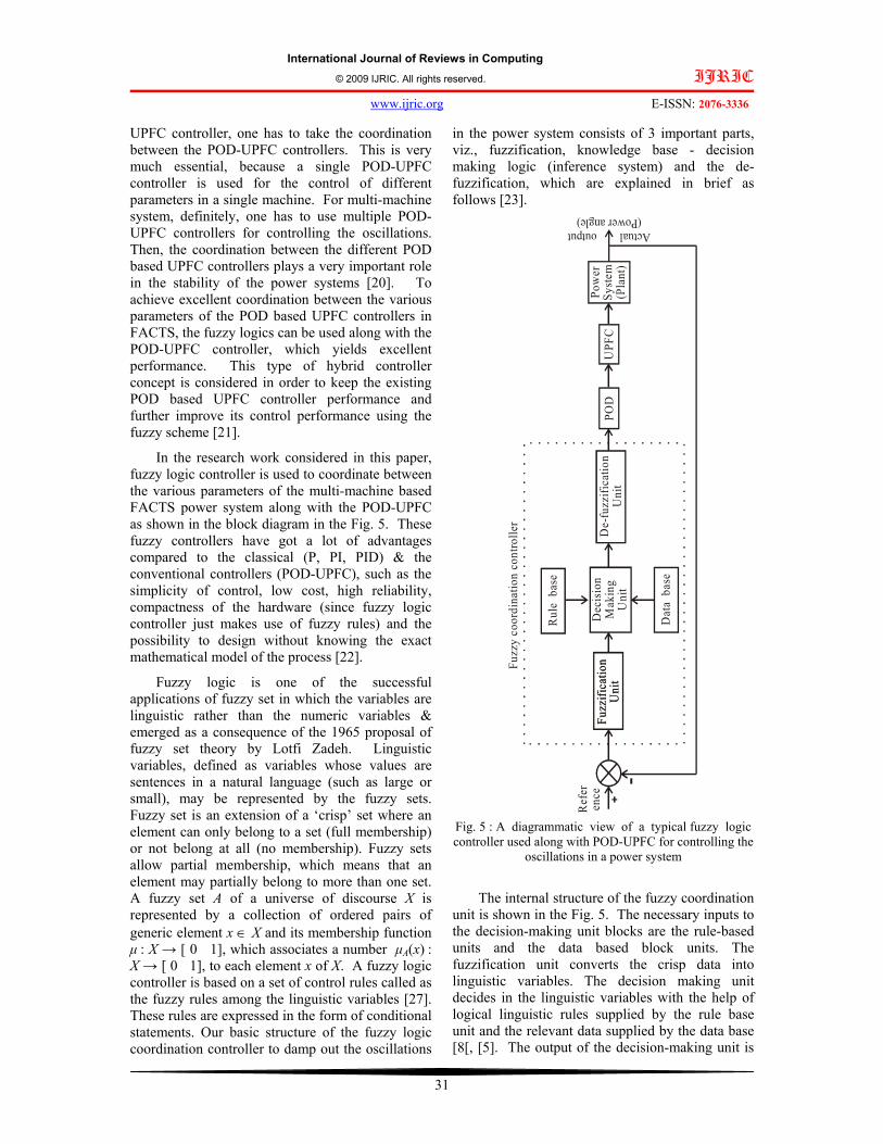
In the research work considered in this paper, fuzzy logic controller is used to coordinate between the various parameters of the multi-machine based FACTS power system along with the POD-UPFC as shown in the block diagram in the Fig. 5. These fuzzy controllers have got a lot of advantages compared to the classical (P, PI, PID) & the conventional controllers (POD-UPFC), such as the simplicity of control, low cost, high reliability, compactness of the hardware (since fuzzy logic controller just makes use of fuzzy rules) and the possibility to design without knowing the exact mathematical model of the process [22].
Fuzzy logic is one of the successful applications of fuzzy set in which the variables are linguistic rather than the numeric variables & emerged as a consequence of the 1965 proposal of fuzzy set theory by Lotfi Zadeh. Linguistic variables, defined as variables whose values are sentences in a natural language (such as large or small), may be represented by the fuzzy sets. Fuzzy set is an extension of a ‘crisp’ set where an element can only belong to a set (full membership) or not belong at all (no membership). Fuzzy sets allow partial membership, which means that an element may partially belong to more than one set. A fuzzy set A of a universe of discourse X is represented by a collection of ordered pairs of generic element x ∈ X and its membership function µ
: X → [ 0 1], which associates a number µA(x)
:
X → [ 0 1], to each element x of X. A fuzzy logic controller is based on a set of control rules called as the fuzzy rules among the linguistic variables [27]. These rules are expressed in the form of conditional statements. Our basic structure of the fuzzy logic coordination controller to damp out the oscillations
in the power system consists of 3 important parts, viz., fuzzification, knowledge base - decision making logic (inference system) and the de-fuzzification, which are explained in brief as follows [23].
Rul
e b
ase
Dec
isio
n M
akin
gU
nit
Fuzz
ifica
tion
Uni
tD
e-fu
zzifi
catio
nU
nit
Dat
a b
ase
Fuzz
ifica
tion
Uni
tPO
D
Actual output(Power angle)
Ref
eren
ceU
PFC
Pow
er
Syst
em(P
lant
)
Fuzz
y co
ordi
natio
n co
ntro
ller
Fig. 5 : A diagrammatic view of a typical fuzzy logic controller used along with POD-UPFC for controlling the
oscillations in a power system
The internal structure of the fuzzy coordination unit is shown in the Fig. 5. The necessary inputs to the decision-making unit blocks are the rule-based units and the data based block units. The fuzzification unit converts the crisp data into linguistic variables. The decision making unit decides in the linguistic variables with the help of logical linguistic rules supplied by the rule base unit and the relevant data supplied by the data base [8[, [5]. The output of the decision-making unit is

International Journal of Reviews in Computing © 2009 IJRIC. All rights reserved. IJRIC
www.ijric.org E-ISSN: 2076-3336
32
given as input to the de-fuzzification unit and the linguistic variables of the signal are converted back into the numeric form of data in the crisp form [5]. The decision-making unit uses the conditional rules of ‘IF-THEN-ELSE’, which can be observed from the algorithm mentioned below [24]. In the fuzzification process, i.e., in the first stage, the crisp variables PUPFC-1 and PUPFC-2 are converted into fuzzy variables or the linguistics variables [7].
The fuzzification maps the 2 input variables to linguistic labels of the fuzzy sets. The fuzzy coordinated controller uses the linguistic labels : {(Small S mf1), (Medium M mf1), (Big B mf2)}. Each fuzzy label has an associated membership function. The membership function of triangular type is used in our work & is shown in the Fig. 6. The inputs are fuzzified using the 3-fuzzy sets (S, M, B). Power inputs of UPFC 1 and UPFC 2 are given to fuzzy controller. The output of the fuzzy-converter will genarate the pulses, which are further given as inputs to the POD [25].
PUPFC-1
PUPFC-2
FUZZYSVPWM
(Mandani)
Ouput
Fig. 6 : FIS Fuzzy editor with 2 inputs and 1 outputs
The output of the fuzzy-converter will genarate the pulses, which are further given as inputs to the POD [25]. The membership function of the small set is given by the Eqn. (2) as [10]
⎪⎩
⎪⎨
⎧
>≤≤−+−
−<
=px
pxNpNpx
Npxxsmall
0)(
)(1)(µ (2)
where x, is the inputs to the Fuzzy-POD-UPFC controllers, namely the PUPFC-1 and PUPFC-2. From this equation, we see that when x is less than (p− N), the value of the function is 1, when it is greater than p, the value is zero. In between the 2 inequalities, the value of the function is having a decreasing slope of −1 [26].
The membership function of the big set is given by the Eqn. (3) as [10]
( )⎪⎩
⎪⎨
⎧
+>+≤≤−
<
=)(1
)(0
)(Npx
NpxpNpx
pxxBigµ (3)
The membership function of the medium set is given by the Eqn. (4) as [10]
⎪⎪
⎩
⎪⎪
⎨
⎧
+>+≤≤++−≤≤−−+
−<
=
)(1)()(
)()()(0
)(
NpxNpxpN
pNxpxNpN
pNxNpx
xBigµ (4)
Note that p is the parameter which can be determined on the basis of the rated values of the controllers [27]. The whole concept of the membership functions as mentioned in the above Eqns. (2) to (4) which are used in generating the rule base for the fuzzification process is explained graphically in the form of a diagram in the Fig. 7.
p n− p p n+ x1
Smallmf1
Mediummf2
Bigmf3
µ(x)
0
1
Fig. 7 : Membership function used in the fuzzification process.
The developed fuzzy rules included in the fuzzy coordinated controller is given below in the form of an algorithm as follows :
1. If (input_1 is mf1) and (input_2 is mf1) then (output_1 is mf3)(1)
2. If (input_1 is mf1) and (input_2 is mf2) then (output_1 is mf2)(1)
3. If (input_1 is mf1) and (input_2 is mf3) then (output_1 is s1)(1)
4. If (input_1 is mf2) and (input_2 is mf1) then (output_1 is mf3)(1)
5. If (input_1 is mf2) and (input_2 is mf2) then (output_1 is mf2)(1)
6. If (input_1 is mf2) and (input_2 is mf3) then (output_1 is s1)(1)
7. If (input_1 is mf3) and (input_2 is mf1) then (output_1 is mf3)(1)
8. If (input_1 is mf3) and (input_2 is mf2) then (output_1 is mf2)(1)
9. If (input_1 is mf3) and (input_2 is mf3) then (output_1 is s1)(1)

International Journal of Reviews in Computing © 2009 IJRIC. All rights reserved. IJRIC
www.ijric.org E-ISSN: 2076-3336
33
The control decisions are made based on the fuzzified variables. The inference involves a set of rules for determining the output decisions [28]. As there are 2 input variables PUPFC-1 and PUPFC-2 & three fuzzified variables (S, M, B), the fuzzy logic coordination controller has a set of 9 rules for each POD based UPFC controller. To determine the degree of memberships for the output variables, the concept of min-max inference is used. Note that both the controllers use the same rule base system [29]. Only the input is exchanged. The rule base for the decision-making unit is written as shown in the table II as follows :
PUPFC1 → Small set S mf1
Medium set M mf2
Big Set B
mf3 PUPFC2 ↓
Small set S mf1 B M S Medium set M mf2 B M S Big set B mf3 M S S
Table II : The 9-fuzzy rules used for determining the output decisions (Inference table) rule base used for the
control purposes
Now, the 9 output variables of the inference system are the linguistic variables and they must be converted into numerical output, i.e., they have to be de-fuzzified [30]. This process is what is called as de-fuzzification.
Defuzzification is the process of producing a quantifiable result in fuzzy logic. The defuzzifcation transforms a fuzzy set information into a numeric data information. This operation along with the operation of fuzzification is critical to the design of fuzzy systems as both of these operations provide nexus between the fuzzy set domain and the real valued scalar domain [31].
There are so many methods to perform the deffuzification, viz., centre of gravity method, centre of singleton method, maximum methods, the marginal properties of the centroid methods & so on. In our work, we use the centre of gravity method. The output of the fuzzy-coordination controller according to the centre of gravity method is given by the Eqn. (5) as
( )
( )∑
∑
=
== 9
1
9
1.
iic
ii
ic
u
uuu
µ
µ, (5)
where ui corresponds to the value of the control output for which the membership values in the output sets are equal to unity [32].
The output of the fuzzy-coordination unit is further given as the input to the POD, which in turn is given as input to the UPFC controller. The POD (Power Oscillation Damping) uses 5 individual blocks, viz., the amplification block, the wash out link, 2 stage of lag-lead blocks and a limiter.
The modeling of this is done in Simulink and is shown in the Fig. 9. Note that the inputs to controller (PUPFC-1 and PUPFC-2) are the active power flow through the UPFCs. The output signal of the fuzzy-POD combination is the command signals to the UPFCs [33]. Thus, in this way, the conventional POD controllers are tuned by making use of the fuzzy-coordination controllers.
The control signal generated from this combined fuzzy-POD-UPFC is given to the multi-machine model which is further used to dampen the oscillations [34]. The main advantage of putting the fuzzy coordination controller before the UPFC-POD in modeling is the amplification part of the conventional controller being modified by the fuzzy coordination unit, thus increasing the power system stability. The overall structure of the fuzzy-coordination controller used in the work is shown in the block-diagram in the Fig. 8.

International Journal of Reviews in Computing © 2009 IJRIC. All rights reserved. IJRIC
www.ijric.org E-ISSN: 2076-3336
34
s T
1 +
s w Tw
P UPF
C-1
Fuzz
yC
oord
inat
orC
ontro
ller
1
1 +
sT
1 +
s 1 T2
1 +
sT
1 +
s3 T4
LimiterV max
V min
Cont
rol s
igna
l to
UPF
C-1
s T
1 +
s w Tw
P UPF
C-2
Fuzz
yC
oord
inat
orC
ontro
ller
2
1 +
sT
1 +
s 1 T2
1 +
sT
1 +
s3 T4
LimiterV max
V min
Cont
rol s
igna
l to
UPF
C-2
Fina
l con
trol
sign
al to
th
e pl
ant
UPF
CCo
ntro
ller
1
UPF
CC
ontro
ller
2
POD
Con
trolle
r - 1
POD
Con
trolle
r - 2
Fig. 8 : The Fuzzy coordinated-POD-UPFC controller
LimiterAmplificationBlock
Wash-out l ink Two lag-lead blocks in cascade
1Out1
tf([0.05 1],[0.05 1])tf([0.05 1],[0.05 1])tf([3 0],[3 1])0.7
Gain
1In1
Fig. 9 : Transfer function model of one of the 2 POD controllers used for simulation purposes with the numerical values
3. DEVELOPMENT OF THE SIMULINK
MODEL In this section, we present the development of
the Simulink model for the multi-machine power system with and without the controller. The Fig. 10 shows the simulation model of 3-generator, 9-bus system installed with two Fuzzy-POD-UPFC controllers, i.e., first one between 2nd and the 3rd bus and second one is at 6th and 7th bus. The entire system modeled in Simulink is a closed loop feedback control system consisting of the plants, controllers, comparators, feedback systems, the mux, de-mux, integrators, state-space models, sub-
systems, transformers, the output sinks (scopes) & the input sources [39].
The Simulink model is developed from the basic functions available in the Simulink library & from the various tool-boxes available. Transformers are used for voltage step up & step down purposes. The sub-system shown in the Simulink model consists of FACTS POD controller and it involves a 3-stage first order transfer functions consisting of an amplification block, a wash-out block and mc stages of lead-lag blocks & the limiters [35].
The output signal of the Fuzzy coordinated POD is amplification signal adjusted to the UPFC POD controller & given as input to the UPFC. In this way, the conventional POD controllers are

International Journal of Reviews in Computing © 2009 IJRIC. All rights reserved. IJRIC
www.ijric.org E-ISSN: 2076-3336
35
coordinated dynamically by means of fuzzy-logic & the amplification part of the conventional controller is modified by the fuzzy coordination controllers, thus acting as a pre-amplifier [38]. Fuzzy coordinated controller consists of 3 basic blocks viz., fuzzification, inference, and the de-fuzzification blocks. A set of 9 fuzzy rules are written and called in the form of a file in the developed Simulink model with the controller.
The 3 phase to ground symmetrical fault is made to occur near the first generator for 200 ms from the first cycle to the tenth cycle. In the work considered shown in the Fig. 10, the combined effect of Fuzzy-POD-UPFC is mainly used for power system oscillation damping [37]. The Fig. 11 shows the simulation model of 3-generator, 9-bus system installed without the controllers.
This system is thus, an open loop control system because of the absence of the controller [40]. The 3 phase to ground symmetrical fault is also made to occur near the first generator for 200 ms from the first cycle to the tenth cycle like in the model with the controller. This is done in order to compare the effectiveness of the incorporated controller in the model when the fault takes place with the model without the controller when the fault takes place [36]. 5. SIMULATION RESULTS
Simulations are carried out in Matlab 7. The simulation was run for 2 secs with & without the
controller. The step size for the simulation was taken to be very small so that we get very accurate results. For the software implementation purposes, we had taken a 3-generator nine bus system with 220 KV line and 100 MW generators. The 3 phase to ground symmetrical fault is made to occur near the first generator for 200 ms from the first cycle to the tenth cycle & is also simulated in the Simulink model. Due to the occurrence of the fault, the simulation results were observed with & without the controller. The fuzzy editor with 2 inputs & 1 output is shown in the Fig. 12. Further, the membership function is shown in the Fig. 13. The 9 fuzzy rules used in the development of fuzzy logic coordination scheme is shown in the Fig. 14. The rule viewer for the same is presented in the Fig. 15.
The response curve of power angle in degrees vs. time is obtained without & with the controller and is shown in the Figs. 16 and 17 respectively. The comparative response curves with & without the controller both is shown in the Fig. 18. It is clearly observed from the simulation results that with the developed controller, the dynamic performance of the power system is quite improved with the incorporation of the fuzzy coordination scheme. It is also observed that with the controller, the power angle characteristics curves exhibit very less overshoots & undershoots, The oscillations are also damped out in a lesser time. The response characteristics take less time to settle & reach the final steady state value.
Continuous
pow ergui
z
1
Unit Delay3
z
1
Unit Delay2 z
1
Unit Delay1
z
1
Unit Delay
timefuzzy
To Workspace4deltafuzzy
To Workspace3
y
To Workspace2
x2
To Workspace1
x1
To Workspace
A
B
C
A
B
C
Vabc
IabcA
B
C
a
bc
Three-PhaseV-I Measurement1
Vabc
IabcA
B
C
a
bc
Three-PhaseV-I Measurement
A B C
a b c
A
B
C
a
b
c
A
B
C
a
b
c
A B C
A B C
Three-PhaseSeries RLC Load2
A B C
Three-PhaseSeries RLC Load1
A B C
In1Out1
Subsystem4
In1
Conn1
Conn2
Conn3
Conn4
Conn5
Conn6
Conn7
Conn8
Conn9Subsystem2
In1
Conn1
Conn2
Conn3
Conn4
Conn5
Conn6
Conn7
Conn8
Conn9
Subsystem1In1Out1
Subsystem
V*
VI*
V*
VI*
Out1ABC
Power Plant #1Pnom=1000 MW3
Out1ABC
Power Plant #1Pnom=1000 MW2
Out1ABC
Power Plant #1Pnom=1000 MW1
m Delta
Fuzzy Logic Control ler2
Fuzzy Logic Control ler
Iabc*
IabcPulses
Current Regulator2
Iabc*
IabcPulses
Current Regulator
Clock
AB
C
ab
c
B4
Vabc
IabcPQ
3-phase Instantaneous
Active & Reactive PowerVabc
IabcPQ
3-phase
Fig. 10 : The developed Simulink model of a 3-machine, 9-bus system with Fuzzy-POD-UPFC (with controller)

International Journal of Reviews in Computing © 2009 IJRIC. All rights reserved. IJRIC
www.ijric.org E-ISSN: 2076-3336
36
13.8kV 1000 MVA
B 3 B 9
Generator side 1 system
13.8kV 1000 MVA
Generator side 3 system
Generator 1Generator 2
Generator 3
Load 1 Load 4
Load 2
Load 3
2Out2
1Out1
6C1
5B3
4A1
3C
2B
1A
Continuous
pow ergui
timewithout
To Workspace
A
B
C
A
B
C
A B C
a b c
A
B
C
a
b
c
A
B
C
a
b
c
A B C
A B C
A B CA B C
Scope3
m
Pref
Pm
Vf
Reg_M2
m
Pref
Pm
Vf
Reg_M1
0.50.5
Out1
A
B
C
Out1
A
B
C
Out1
A
B
C
m Delta
Clock
Va
Iab
A
B
C
a
b
c
bc
bc
A
B
C
a
b
c
A
B
C
a
b
cB 8
A B C
a b cB 6
A
B
C
a
b
c
B 5A
B
C
a
b
c
B 4
A B C
a b cB 3
A
B
C
a
b
c
B 2
A
B
C
a
b
c
B 1
Pm
Vf _
m
A
B
C1000 MVA1
A
B
C
a
b
c
1000 MVA 13.8 kV/230 kV1
A
B
C
a
b
c
1000 MVA 13.8 kV/230 kV
Pm
Vf _
m
A
B
C1000 MVA
Fig. 11 : The developed Simulink model of a 3-machine, 9-bus system without Fuzzy based UPFC-P OD
(without controller)
Fig. 12 : FIS Fuzzy editor with 2 inputs & 1 output
Fig. 13 : Developed membership functions using the Simulink
Fig. 14 : 9-Fuzzy rules used in the development of the fuzzy logic coordination scheme
Fig. 15 : Rule viewer for 2 inputs & one output

International Journal of Reviews in Computing © 2009 IJRIC. All rights reserved. IJRIC
www.ijric.org E-ISSN: 2076-3336
37
Fig. 16 : Simulation result of power angle v/s time (without Fuzzy-POD-UPFC)
Fig. 17 : Simulation result of power angle v/s time (with UPFC & fuzzy control)
Fig. 18 : Comparison of the simulation results of power angle v/s time
(without UPFC & with UPFC & fuzzy control) 6. CONCLUSIONS
A FACTS based multi-machine power system comprising of 3 generators, 9 buses, 3 loads with and without the 2 Fuzzy-POD-UPFC controllers was considered in this paper. Simulink models were developed in Matlab 7 with & without the Fuzzy-POD-UPFC controllers for the considered multi-machine model in order to damp out the oscillations. The control strategy was also developed by writing a set of fuzzy rules. The fuzzy control strategy was designed based on the conventional POD-UPFC controller & put before the POD-UPFC in the modeling.
The main advantage of putting the fuzzy coordination controller before the POD-UPFC in modeling is the amplification part of the conventional controller being modified by the fuzzy coordination unit, thus increasing the power system stability. Simulations were run in Matlab 7 & the results were observed on the scope. Graphs of power angle vs. time were observed with and without the controller. From the simulation results, it was observed that without the Fuzzy-POD-UPFC
controller, the nine bus system will be having more disturbances, while we check the power angle on the first generator.
There are lot of ringing oscillations (overshoots / undershoots) & the output takes a lot of time to stabilize, which can be observed from the simulation results. But, from the incorporation of the Fuzzy-POD-UPFC coordination system in loop with the plant gave better results there by reducing the disturbances in the power angle and also the post fault settling time also got reduced a lot. The system stabilizes quickly, thus damping the local mode oscillations and reducing the settling time immediately after the occurrence of the fault.
The developed control strategy is not only simple, reliable, and may be easy to implement in real time applications. The performance of the developed method in this paper thus demonstrates the damping of the power system oscillations using the effectiveness of Fuzzy-POD-UPFC coordination concepts over the damping of power system oscillations without the Fuzzy-POD-UPFC coordination scheme. NOMENCLATURE
UPFC Unified Power Flow Controller FACTS Flexible AC Transmission System POD Power Oscillation Damping PSOC Power System Operation & Control IEEE Institute of Electrical & Electronics SVC Static Var Compensator TCSC Thyristor Controlled Series Compensator TCPS Thyristor Controlled Phase Shifter SSSC Static Synchronous Series Compensator STATCOM Static Synchronous Compensator DC Direct Current AC Alternating Current FLC Fuzzy Logic Control PD Proportional Derivative PID Proportional Integrator Derivative
REFERENCES
[1]. L. Gyugi, “Unified Power flow concept for flexible AC transmission systems”, IEE Proc., Vol. 139, No. 4, pp. 323–332, 1992.
[2]. M. Noroozian, L. Angquist, M. Ghandari, and G. Anderson, “Use of UPFC for optimal power flow control”, IEEE Trans. on Power Systems, Vol. 12, No. 4, pp. 1629–1634, 1997.
[3]. Nabavi-Niaki and M.R. Iravani, “Steady-state and dynamic models of unified power flow controller (UPFC) for power system studies”, IEEE’96 Winter Meeting, Paper 96, 1996.
[4]. C.D. Schauder, D.M. Hamai, and A. Edris. “Operation of the Unified Power Flow

International Journal of Reviews in Computing © 2009 IJRIC. All rights reserved. IJRIC
www.ijric.org E-ISSN: 2076-3336
38
Controller (UPFC) under Practical constraints”, IEEE Trans. On Power Delivery, Vol. 13, No. 2. pp. 630~639, Apr. 1998.
[5]. Gyugyi, L., “Unified power flow controller concept for flexible AC transmission systems”, IEE Proc. Gener. Transm. Distrib., No.139, pp. 323-331, 1992
[6]. S.N. Dhurvey and V.K. Chandrakar: “Performance Comparsion of UPFC in Coordination with Optimized POD and PSS On Damping of Power System Oscillations”, WSEAS Transactions on Power Systems, Issue 5 , Vol. 3 , pp. 287-299, May 2008.
[7]. V.K.Chandrakar, A.G.Kothari, “RBFN Based UPFC for Improving transient stability Performance”, WSEAS Transactions on Power Systems, Issue 1 , Vol. 2 , pp.1-6 , Jan 2007.
[8]. K.R. Padiyar , K. Uma Rao, “Modeling and Control of UPFC for Transient Stability”, Elsevier Journal of Electrical Power Energy Systems, N0. 21, pp. 1- 11, 1999.
[9]. H.F. Wang, M. Jazaeri, Y.J. Cao, “Operating modes and control interaction analysis of unified power flow controllers”, IEE Proc., Gener. Transm. Distrib., Vol. 152, Issue 2, pp. 264–270, Mar. 2005.
[10]. Lijun Cai, Istvan Erlich, “Fuzzy coordination of FACTS controllers for damping power system oscillations”, Proc. Of the Int. Symp. On Modern Electronic Power Systems, Wroclaw, pp. 251-256, Sept. 11-13, 2002.
[11]. A. E. Hammad, “Analysis of Power System Stability Enhancement by Static VAR Compensators”, IEEE Trans. PWRS, Vol. 1, No. 4, pp. 222–227, 1986.
[12]. S. Lee and C. C. Liu, “An Output Feedback Static VAR Controller for the Damping of Generator Oscillations”, Electric Power System Research, Vol. 29, pp. 9–16, 1994.
[13]. A. Hasanovic and A. Feliachi, “Genetic Algorithm Based Inter-Area Oscillation Damping Controller Design Using MATLAB”, Power Eng. Society Summer Meeting 2002 IEEE, Vol. 3, pp. 1136 –1141, 21-25 Jul 2002.
[14]. M.R. Iravani, P.L. Dandeno, K.H. Nguyen, D. Zhu, and D. Maratukulam, “Applications of Static Phase Shifters in Power Systems”, IEEE Trans. Power Delivery, Vol. 9, No.3, pp. 1600–1608, 1994.
[15]. M.A. Abido, “Thyristor Controlled Phase Shifter Based Stabilizer Design Using Simulated Annealing Algorithm”, Intl. Conf. Electric Power Engineering, PowerTech,
Budapest, Paper 99, pp. 307, 29 Aug.–2 Sept. 1999.
[16]. A. A. Hashmani, Youyi Wang, and T. Lie, “Design and Application of a Nonlinear Coordinated Excitation and TCPS Controller in Power Systems”, Proc. the 2001 American Control Conf., Vol. 2, pp. 811–816, 25–27 Jun. 2001.
[17]. X.R. Chen, N.C. Pahalawaththa, U.D. Annakkage, and C. Kumble, “Controlled Series Compensation for Improving Stability of Multi-Machine Power Systems”, IEE Proc. Gen. Trans. and Distrib., Vol. 142, No. 4, pp. 361–366, 1995.
[18]. J. Chang and J.H. Chow, “Time-Optimal Control of Power Systems Requiring Multiple Switchings of Series Capacitors”, IEEE Trans. Power Systems, Vol. 13, No. 2, pp. 367–373, 1998.
[19]. Y. Wang, R.R. Mohler, R. Spee, and W. Mittelstadt, “Variable-Structure Facts Controllers for Power System Transient Stability”, IEEE Trans. Power Systems, 7(1)(1992), pp. 307–313.
[20]. M.A. Abido, “Genetic-Based TCSC Damping Controller Design for Power System Stability Enhancement”, Intl. Conf. Electric Power Engineering - 1999, PowerTech Budapest 99, pp. 165, 29 Aug.–2 Sep. 1999.
[21]. A. Nabavi-Niaki, and M.R. Iravani, “Steady-State and Dynamic Models of Unified Power Flow Controller (UPFC) for Power System Studies”, IEEE Trans. Power Systems, Vol. 11, No. 4, pp. 1937–1943, 1996.
[22]. H.F. Wang, “Damping Function of Unified Power Flow Controller”, IEE Proc. Gen. Trans. and Distrib., Vol. 146, No. 1, pp. 81–87, 1999.
[23]. H.F. Wang, “Application of Modeling UPFC Into Multi-Machine Power Systems”, IEE Proc. Gen. Trans. and Distrib., Vol. 146, No. 3, pp. 306–312, 1999.
[24]. Y. H. Song, A. T. Jons, “Flexible AC Transmission Systems (FACTS)”, IEE Power and Energy Series, pp. 30, 1999.
[25]. S. Hongbo, D.C Yu. Luo Chunlei, “A novel method of power flow analysis with unified power flow controller (UPFC)”, Power Engineering Society Winter Meeting, 2000, pp. 2800 – 2805, Vol. 4, 23-27 Jan. 2000.
[26]. Narain G. Hingorani, Laszlo Gyugyi “Understanding FACTS: Conceptsand Technology of Flexible AC Transmission Systems”, Power electronics sponsored by the Institute of Electrical and Electronics

International Journal of Reviews in Computing © 2009 IJRIC. All rights reserved. IJRIC
www.ijric.org E-ISSN: 2076-3336
39
Engineers, Inc. 3 Park Avenue, New York, NY 10016-5997, 2000.
[27]. A. A. Eldamaty, S. O. Faried, S. Aboreshaid, “Damping Power System Oscillations Using a Fuzzy Logic Based Unified Power Flow Controller”, J. Electrical and Computer Engineering, pp. 1950 –1953, 2005.
[28]. R.P Kalyani, G.K. Venayagamoorthy, M. Crow, “Neuroidentification of system parameters for the shunt & series branch control of UPFC”, Power Engineering Society General Meeting, 2003, IEEE Vol. 4, 13-17 Jul. 2003.
[29]. S. Kannan, S. Jayaram, M. M. A. Salama, “Real and Reactive Power Coordination for a Unified Power Flow Controller”, IEEE Transactions on Power Systems, Vol. 19, Issue 3, pp. 1454 – 1461, 2004.
[30]. R. Orizondo, R. Alves, “UPFC Simulation and Control Using the ATP/EMTP and MATLAB/Simulink Programs”, Transmission & Distribution Conference and Exposition, IEEE/PES, pp. 1 – 7, 2006.
[31]. D. Thukaram, L. Jenkins, K. Visakha, “Improvement of System Security with Unified Power Flow Controller at Suitable Locations under Network Contingencies of Interconnected Systems”, IEE Proceedings Generation, Transmission and Distribution, Vol. 152, Issue 5, pp. 682 – 690, 2005.
[32]. H. Fujita, Y. Watanabe, H. Akagi, “Control and Analysis of a Unified Power Flow Controller”, IEEE Transactions on Power Electronics, Vol. 14, Issue 6, pp. 1021 – 1027, 1999.
[33]. B. Lu, L. Hou, B. Li, Y. Liu, “A New Unified Power Flow Fuzzy Control Method”, Jr. Innovative Computing, Information and Control, Second International Conference, pp. 479 – 479, 2007.
[34]. Y. Qing, L. Norum, T. Undeland, S. Round, “Investigation of Dynamic Controllers for a Unified Power Flow Controller”, Trans. On Industrial Electronics, Control, and Instrumentation, Vol. 3, pp. 1764-1769, 1996.
[35]. M. W. Mustafa, A. A. Zin, A.F. Kadir, “Steady State Analysis of Power Transmission Using Unified Power Flow Controller”, Transmission and Distribution Conference and Exhibition, Vol. 3, pp. 2049 – 2053.
[36]. P. K. Dash, S. Mishra, and G. Panda, “Damping Multi-modal Power System Oscillation Using a Hybrid Fuzzy Controller for Series Connected FACTS Devices”, IEEE
Trans. on Power Systems, Vol. 15, No. 4, pp. 1360–1366, Nov. 2000.
[37]. P. Korba, F.R. Segundo, B. Chaudhuri, “Advanced tuning of POD controllers for EPS using FACTS”, Proc. of the 17th World Congress, IFAC, Seoul, Korea, , pp. 11076-11077, Jul. 6-11, 2008.
[38]. Rusejla Sadikovi´C, “Use of FACTS Devices for Power Flow Control and Damping of Oscillations in Power Systems”, Doctoral Thesis, Swiss Federal Institute of Technology, Zurich, 2006.
[39]. Lutfu Saribulut, Mehmet Tumay, and Đlyas Eker, “Performance Analysis of Fuzzy Logic Based Unified Power Flow Controller”, Proc. World Academy of Science, Engineering and Technology, Vol. 35, ISSN 2070-3740, pp. 321-327, Nov. 2008.
[40]. P.K. Dasha, S. Mishra, “Damping of multimodal power system oscillations by FACTS devices using non-linear Takagi-Sugeno fuzzy controller”, Proc. Electrical Power and Energy Systems, Vol. 25, pp. 481–490, 2003.
D. Obulesu received the B.E. degree in EEE from STJ Institute of Technology, Ranebennur, Karnataka, India from Karnataka University and M.Tech. in Power Electronics from Dr. M.G.R. University in the year 2000
and 2005 respectively. He has got a teaching experience of nearly 08 years. Currently, he is working as Associate Professor in Madanapalli Institute of Technology & Sciences, Madanapally, Chittoor Dist, Andhra Pradesh, India in the Dept. of Electrical & Electronics Engg. & simultaneously doing his Ph.D. (Research Scholar) in Electrical & Electronics Engg. from the prestigious Jawaharlal Nehru Technological University (JNTU), Hyderabad, Andhra Pradesh, India. He has published a number of research papers in various national & international journals & conferences. His area of interests are neural networks, fuzzy logic, artificial intelligence, power electronics, Matlab, FACTS, etc.

International Journal of Reviews in Computing © 2009 IJRIC. All rights reserved. IJRIC
www.ijric.org E-ISSN: 2076-3336
40
Dr. S. F. Kodad received the B.E. degree in EEE from STJ Institute of Technology, Ranebennur, Karnataka, India from Karnataka University and the M.Tech. degree in Energy Systems Engg. from JNTU, Hyderabad, India in the year
1992. He received his Ph.D. degree in Electrical Engg. from JNTU, Hyderabad, India in the year 2004. He has got a teaching experience of nearly 21 years. Currently, he is working as Professor & Head in Aurora College of Engg., Hyderabad, Andhra Pradesh, India in the Dept. of Electrical & Electronics Engg. He has published a number of papers in various national & international journals & conferences & done a number of in-house & industry projects. He has also presented a number of guest lectures and various seminars and participated in a number of courses, seminars, workshops, symposiums in the various parts of the country in different institutions and also conducted a few courses. He is also guiding a number of Ph.D. students. His area of interests are neural networks, fuzzy logic, power electronics, power systems, artificial intelligence, Matlab, Renewable energy sources, etc.
Dr. B. V. Sankar Ram received the B.E. degree in Electrical Engg. from Osmania University & M.E. degree in Power Systems from Osmania University, Hyderabad, Andhra Pradesh, India. He received his Ph.D.
degree in Electrical Engg. from JNTU, Hyderabad, India. He obtained Diploma in Candidate Management Finance. He has got a teaching experience of more than 20 years. Currently, he is working as Professor in JNTU College of Engg. Hyderabad, India in the Dept. of Electrical Engg. He has published a number of papers in various national & international journals & conferences & done a number of in-house & industry projects. He is also guiding a number of research scholars in various topics of engg. He has specialized in power systems. His research interests include power system reliability and Flexible AC Transmission systems, power electronics & it is applications.