Embed Size (px)
Citation preview
ISSN 0021�3640, JETP Letters, 2009, Vol. 89, No. 5, pp. 229–232. © Pleiades Publishing, Ltd., 2009.
229
1 Recently due to the work of Veselago [1], muchattention has been paid to a so called perfect lens,whose properties are due to particular features ofmedia with negative refractive index. Keen interest tothis theme was aroused by the work of Pendry [2],where because of impossibility to produce media withnegative refractive index he had proposed to usemetallic films with ε = –1 for near field focusing. Theattempts to make a perfect lens have already involvedinteresting experiments on optical near field focusing(superlenses [3], hyperlenses [4, 5], and nanolenses[6]). However, the Veselago perfect lenses [1] with n =–1 have not yet been achieved, and as will be shownbelow, they cannot be realized due to the reasons notat all connected with technical difficulties of making ametamaterial with negative refractive index. The fact isthat a conventional picture of operation of a perfectlens is incorrect, because it disagrees with the standardMaxwell equations.
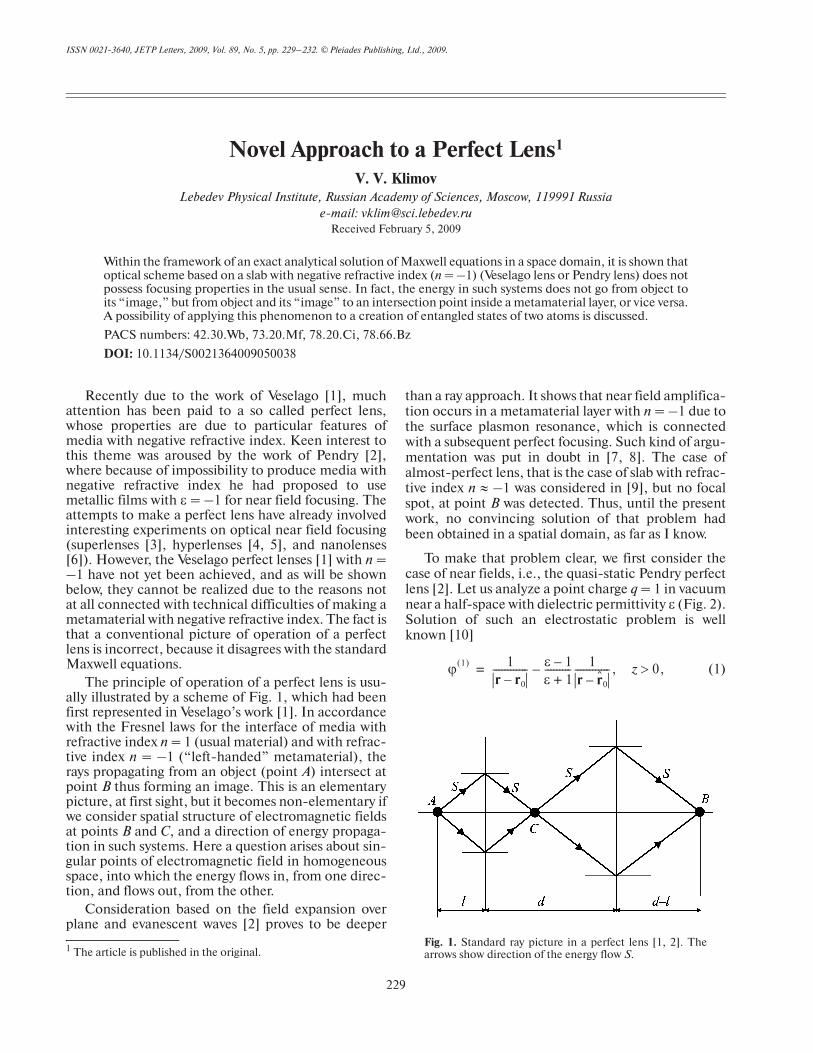
The principle of operation of a perfect lens is usu�ally illustrated by a scheme of Fig. 1, which had beenfirst represented in Veselago’s work [1]. In accordancewith the Fresnel laws for the interface of media withrefractive index n = 1 (usual material) and with refrac�tive index n = –1 (“left�handed” metamaterial), therays propagating from an object (point A) intersect atpoint B thus forming an image. This is an elementarypicture, at first sight, but it becomes non�elementary ifwe consider spatial structure of electromagnetic fieldsat points B and C, and a direction of energy propaga�tion in such systems. Here a question arises about sin�gular points of electromagnetic field in homogeneousspace, into which the energy flows in, from one direc�tion, and flows out, from the other.
Consideration based on the field expansion overplane and evanescent waves [2] proves to be deeper
1 The article is published in the original.
than a ray approach. It shows that near field amplifica�tion occurs in a metamaterial layer with n = –1 due tothe surface plasmon resonance, which is connectedwith a subsequent perfect focusing. Such kind of argu�mentation was put in doubt in [7, 8]. The case ofalmost�perfect lens, that is the case of slab with refrac�tive index n ≈ –1 was considered in [9], but no focalspot, at point B was detected. Thus, until the presentwork, no convincing solution of that problem hadbeen obtained in a spatial domain, as far as I know.
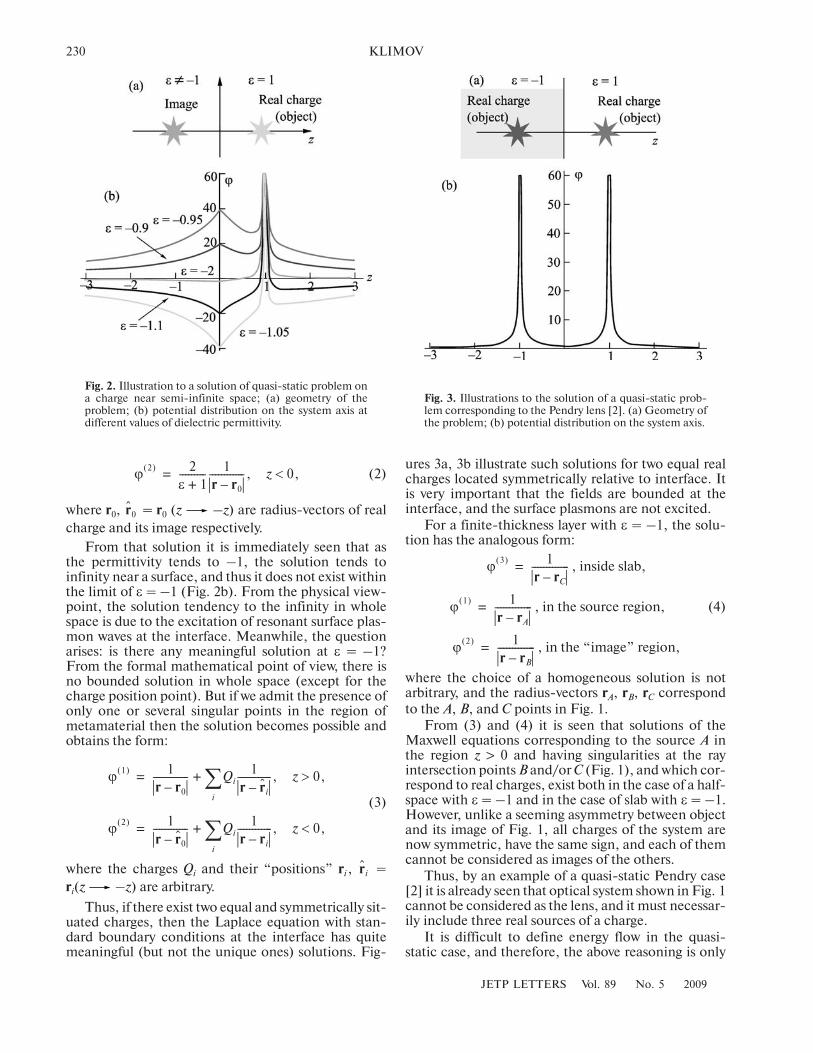
To make that problem clear, we first consider thecase of near fields, i.e., the quasi�static Pendry perfectlens [2]. Let us analyze a point charge q = 1 in vacuumnear a half�space with dielectric permittivity ε (Fig. 2).Solution of such an electrostatic problem is wellknown [10]
(1)ϕ1( ) 1
r r0–������������ ε 1–
ε 1+��������� 1
r r̂0–������������, z– 0,>=
Novel Approach to a Perfect Lens1
V. V. KlimovLebedev Physical Institute, Russian Academy of Sciences, Moscow, 119991 Russia
e�mail: [email protected] February 5, 2009
Within the framework of an exact analytical solution of Maxwell equations in a space domain, it is shown thatoptical scheme based on a slab with negative refractive index (n = –1) (Veselago lens or Pendry lens) does notpossess focusing properties in the usual sense. In fact, the energy in such systems does not go from object toits “image,” but from object and its “image” to an intersection point inside a metamaterial layer, or vice versa.A possibility of applying this phenomenon to a creation of entangled states of two atoms is discussed.
PACS numbers: 42.30.Wb, 73.20.Mf, 78.20.Ci, 78.66.Bz
DOI: 10.1134/S0021364009050038
Fig. 1. Standard ray picture in a perfect lens [1, 2]. Thearrows show direction of the energy flow S.
230
JETP LETTERS Vol. 89 No. 5 2009
KLIMOV
(2)
where r0, = r0 (z –z) are radius�vectors of realcharge and its image respectively.
From that solution it is immediately seen that asthe permittivity tends to –1, the solution tends toinfinity near a surface, and thus it does not exist withinthe limit of ε = –1 (Fig. 2b). From the physical view�point, the solution tendency to the infinity in wholespace is due to the excitation of resonant surface plas�mon waves at the interface. Meanwhile, the questionarises: is there any meaningful solution at ε = –1?From the formal mathematical point of view, there isno bounded solution in whole space (except for thecharge position point). But if we admit the presence ofonly one or several singular points in the region ofmetamaterial then the solution becomes possible andobtains the form:
(3)
where the charges Qi and their “positions” ri, =ri(z –z) are arbitrary.
Thus, if there exist two equal and symmetrically sit�uated charges, then the Laplace equation with stan�dard boundary conditions at the interface has quitemeaningful (but not the unique ones) solutions. Fig�
ϕ2( ) 2
ε 1+��������� 1
r r0–������������, z 0,<=
r̂0
ϕ1( ) 1
r r0–������������ Qi
1r r̂i–
������������, zi
∑ 0,>+=
ϕ2( ) 1
r r̂0–������������ Qi
1r ri–
������������, zi
∑ 0,<+=
r̂i
ures 3a, 3b illustrate such solutions for two equal realcharges located symmetrically relative to interface. Itis very important that the fields are bounded at theinterface, and the surface plasmons are not excited.
For a finite�thickness layer with ε = –1, the solu�tion has the analogous form:
, inside slab,
, in the source region, (4)
, in the “image” region,
where the choice of a homogeneous solution is notarbitrary, and the radius�vectors rA, rB, rC correspondto the A, B, and C points in Fig. 1.
From (3) and (4) it is seen that solutions of theMaxwell equations corresponding to the source A inthe region z > 0 and having singularities at the rayintersection points B and/or C (Fig. 1), and which cor�respond to real charges, exist both in the case of a half�space with ε = –1 and in the case of slab with ε = –1.However, unlike a seeming asymmetry between objectand its image of Fig. 1, all charges of the system arenow symmetric, have the same sign, and each of themcannot be considered as images of the others.
Thus, by an example of a quasi�static Pendry case[2] it is already seen that optical system shown in Fig. 1cannot be considered as the lens, and it must necessar�ily include three real sources of a charge.
It is difficult to define energy flow in the quasi�static case, and therefore, the above reasoning is only
ϕ3( ) 1
r rC–�������������=
ϕ1( ) 1
r rA–�������������=
ϕ2( ) 1
r rB–�������������=
Fig. 2. Illustration to a solution of quasi�static problem ona charge near semi�infinite space; (a) geometry of theproblem; (b) potential distribution on the system axis atdifferent values of dielectric permittivity.
Fig. 3. Illustrations to the solution of a quasi�static prob�lem corresponding to the Pendry lens [2]. (a) Geometry ofthe problem; (b) potential distribution on the system axis.
JETP LETTERS Vol. 89 No. 5 2009
NOVEL APPROACH TO A PERFECT LENS 231
the indirect evidence that the usual picture is not cor�rect, and one cannot use the system of Fig. 1 in theregime of a usual lens. For final evidence of that fact,we consider full electrodynamics problem with one orseveral interfaces between the right�handed mediumwith ε = 1, µ = 1 and the left�handed medium withε = –1, µ = –1 (n = –1). One can verify that there isno solution of the Maxwell equations with one sourcein the right�hand medium and without any sources inthe “left�handed” half�space. However, one mayderive explicit solution of the Maxwell equations byadmitting the existence of a finite number of singularpoints, where charges and currents arise.
Consider a case of a single interface between right�and “left�handed” matter. If the right�handed half�space contains a dipole with boundary�parallel orien�tation, then in the left�hand matter the dipole must beplaced, which is directed in the opposite direction atthe mirror�symmetrical point (see Fig. 4). Formallyspeaking, the Hertz vector in the “right�handed”medium has the form:
(5)
and in the “left�handed” medium,
(6)
Using relations between Hertz potential Π and fieldsE, H [11]
(7)
from (5) and (6) we find the electric and magneticfields, which satisfy standard continuity conditions fortangential components, that, should be solution ofMaxwell equation. Note that both (5) and (6) describephase propagation from the source, and energy flowfrom the source (“right�handed” medium) and to thesource (“left�handed” medium).
Π1( ) d0
iω r r0– /c( )exp
r r0–����������������������������������eiω t=
Π2( ) d0
iω r r̂0– /c( )exp
r r̂0–����������������������������������eiω t
.=
E ∇ ∇Π( ) εµ ω/c( )2Π,+=
H iε ω/c( )∇ Π×–=
For the “left�handed” slab, the solution is builtanalogously, and has the form
(8)
where rA, rB, and rC are radius�vectors of ray intersec�tion points A, B, C in Fig. 1. It is very interesting thatthe solution (8) remains valid even in the case l > d, butin this case positions of B and C are inside and outsideslab, respectively. Of course in that case there are nosingularities except for the dipole source at point A andone cannot speak about lens effect.
The picture for the normally oriented dipole is fullyanalogous. In that case, however, one should choose aantisymmetrical combination of Hertz potentials.
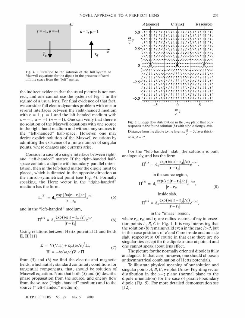
To illustrate physical meaning of our solution andsingular points A, B, C, we plot Umov�Poynting vectordistribution in the y–z plane (normal plane to thedipole orientation) for the case of parallel�boundarydipole (Fig. 5). For more detailed demonstration see[12].
Π1( ) d0
iω r rA– /c( )exp
r rA–����������������������������������e iω t–
,=
in the source region,
Π3( ) d0
iω r rC– /c( )exp
r rC–����������������������������������e iω t–
,=
inside slab,
Π2( ) d0
iω r rB– /c( )exp
r rB–����������������������������������e iω t–
,=
in the “image” region,
Fig. 4. Illustration to the solution of the full system ofMaxwell equations for the dipole in the presence of semi�infinite space from the “left” matter.
Fig. 5. Energy flow distribution in the y–z plane that cor�responds to the found solution (8) with dipole along x�axis.
Distance from the dipole to the layer is l = 3, layer thick�
ness, d = 2l.
ω
c���
232
JETP LETTERS Vol. 89 No. 5 2009
KLIMOV
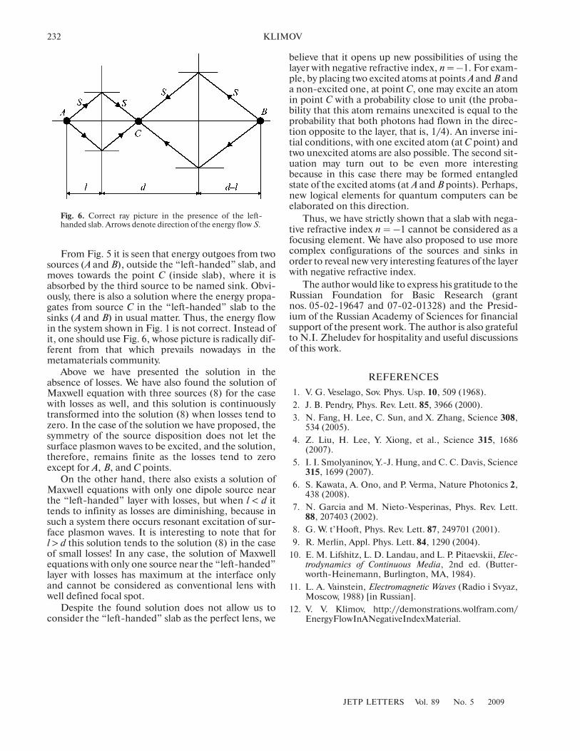
From Fig. 5 it is seen that energy outgoes from twosources (A and B), outside the “left�handed” slab, andmoves towards the point C (inside slab), where it isabsorbed by the third source to be named sink. Obvi�ously, there is also a solution where the energy propa�gates from source C in the “left�handed” slab to thesinks (A and B) in usual matter. Thus, the energy flowin the system shown in Fig. 1 is not correct. Instead ofit, one should use Fig. 6, whose picture is radically dif�ferent from that which prevails nowadays in themetamaterials community.
Above we have presented the solution in theabsence of losses. We have also found the solution ofMaxwell equation with three sources (8) for the casewith losses as well, and this solution is continuouslytransformed into the solution (8) when losses tend tozero. In the case of the solution we have proposed, thesymmetry of the source disposition does not let thesurface plasmon waves to be excited, and the solution,therefore, remains finite as the losses tend to zeroexcept for A, B, and C points.
On the other hand, there also exists a solution ofMaxwell equations with only one dipole source nearthe “left�handed” layer with losses, but when l < d ittends to infinity as losses are diminishing, because insuch a system there occurs resonant excitation of sur�face plasmon waves. It is interesting to note that forl > d this solution tends to the solution (8) in the caseof small losses! In any case, the solution of Maxwellequations with only one source near the “left�handed”layer with losses has maximum at the interface onlyand cannot be considered as conventional lens withwell defined focal spot.
Despite the found solution does not allow us toconsider the “left�handed” slab as the perfect lens, we
believe that it opens up new possibilities of using thelayer with negative refractive index, n = –1. For exam�ple, by placing two excited atoms at points A and B anda non�excited one, at point C, one may excite an atomin point C with a probability close to unit (the proba�bility that this atom remains unexcited is equal to theprobability that both photons had flown in the direc�tion opposite to the layer, that is, 1/4). An inverse ini�tial conditions, with one excited atom (at C point) andtwo unexcited atoms are also possible. The second sit�uation may turn out to be even more interestingbecause in this case there may be formed entangledstate of the excited atoms (at A and B points). Perhaps,new logical elements for quantum computers can beelaborated on this direction.
Thus, we have strictly shown that a slab with nega�tive refractive index n = –1 cannot be considered as afocusing element. We have also proposed to use morecomplex configurations of the sources and sinks inorder to reveal new very interesting features of the layerwith negative refractive index.
The author would like to express his gratitude to theRussian Foundation for Basic Research (grantnos. 05�02�19647 and 07�02�01328) and the Presid�ium of the Russian Academy of Sciences for financialsupport of the present work. The author is also gratefulto N.I. Zheludev for hospitality and useful discussionsof this work.
REFERENCES
1. V. G. Veselago, Sov. Phys. Usp. 10, 509 (1968).
2. J. B. Pendry, Phys. Rev. Lett. 85, 3966 (2000).
3. N. Fang, H. Lee, C. Sun, and X. Zhang, Science 308,534 (2005).
4. Z. Liu, H. Lee, Y. Xiong, et al., Science 315, 1686(2007).
5. I. I. Smolyaninov, Y.�J. Hung, and C. C. Davis, Science315, 1699 (2007).
6. S. Kawata, A. Ono, and P. Verma, Nature Photonics 2,438 (2008).
7. N. Garcia and M. Nieto�Vesperinas, Phys. Rev. Lett.88, 207403 (2002).
8. G. W. t’Hooft, Phys. Rev. Lett. 87, 249701 (2001).
9. R. Merlin, Appl. Phys. Lett. 84, 1290 (2004).
10. E. M. Lifshitz, L. D. Landau, and L. P. Pitaevskii, Elec�trodynamics of Continuous Media, 2nd ed. (Butter�worth�Heinemann, Burlington, MA, 1984).
11. L. A. Vainstein, Electromagnetic Waves (Radio i Svyaz,Moscow, 1988) [in Russian].
12. V. V. Klimov, http://demonstrations.wolfram.com/EnergyFlowInANegativeIndexMaterial.
Fig. 6. Correct ray picture in the presence of the left�handed slab. Arrows denote direction of the energy flow S.

![Novel LVCSR Decoder Based on Perfect Hash Automata and ... · Perfect hashing techniques based on finite-state automata can be very efficient when solving these problems [3, 23]](https://img.dokumen.tips/doc/110x75/5f3b89d7ea2bb5733a4d2d8b/novel-lvcsr-decoder-based-on-perfect-hash-automata-and-perfect-hashing-techniques.jpg)


![MAX VISION Tablet: A Perfect Formulation to Support the ... · posterior pole. The lens capsule may be involved with the higher anterior curvature than posterior of the lens.[3] Lens](https://img.dokumen.tips/doc/110x75/5ffd3e0819710b5969179155/max-vision-tablet-a-perfect-formulation-to-support-the-posterior-pole-the.jpg)