Embed Size (px)
Citation preview

Pressure holding technology & degassing technology
Technomat Nova /Duo Nova
✓ Constant pressure✓ Deaeration✓ Make-up feed✓ Feed evacuation✓ Temperature measurement✓ Oxygen measurement
✓ pH measurement
✓ Conductivity measurement
Remote monitoringRemote control
INNOVATIVE PRESSURE COMPETENCE

2
INNOVATIVE PRESSURE COMPETENCE
With remote monitoring and
remote control you have your system
under control everywhere and
all the time.
Benefit!

Technomat
3
Technomat, the automatic pump-controlled compact station, reveals new
ways for constant pressure and deaeration in heating and cooling circuits.
Barnova Technomat
✓ Keeps the pressure constant in the system with low-noise centrifugal
pumps – even within tight pressure limits
✓ Depressurized operated membrane collecting tank
✓ Deaerates system and refilling water in a controlled manner!
✓ Back feeds refilling water in a controlled manner
✓ Discharges system water in a controlled manner
✓ Monitors in conjunction with the multi-language Barnova SPS control system:
· Membrane rupture
· pH and conductivity
· Temperature and oxygen content of the system retaining water
· Operating states with both time and date particulars
· Warning and malfunction notifications
✓� Transfers all operating states onto control systems
✓ Remote monitoring and control through use
of intelligent hardware
✓ Higher operational security through use of
a second pressure transducer.
Thanks to its unique compact design, the Barnova Technomat can
be installed in both an easy-to-operate and ready-to-operate manner.
In short: “How can air problems be dealt without any manual venting?”
By using the Barnova Technomat!
Barnova TechnomatNOVA/DUO NOVAThe constant pressure station that shows what it can do!
Reference property item – Skyper high-rise offices, Frankfurt a.M.
The Technomat is the pressure holding
station that measures oxygen content,
pH value and conductivity depending on
the temperature and therefore always
knows what it‘s doing!
Benefit!

4
INNOVATIVE PRESSURE COMPETENCE
The Barnova VPN solution for remote monitoring, remote control, networking and alarms
With the VPN-M2M-NETWORK you are directly connected to the Barnova SPS. This makes it possible not only
to view operating states, warnings and malfunctions, but also to intervene directly. Diagnoses, reconfiguration and
resetting parameters can all be done from the convenience of your own home.
✓ Multi-client system, user groups scalable to any level
✓ Highest security standards through certificate-based VPN connections and firewall
✓ Low investment and operating costs
✓ Reduction of travel and personnel costs
✓ Troubleshooting and issue resolution 24/7
✓ Automatic notification of warnings and/or malfunctions
VPN-M2M-NETWORKS
www
ww
ww
ww VPN Server
Barnova SPS
Smartphone
PC BPC A
Laptop

Technomat
5
Barnova remote control, remote monitoring webshots
Operator
Overview

6
INNOVATIVE PRESSURE COMPETENCE
Barnova remote control, remote monitoring webshotsService menu
Data logger
Service menu

Technomat
7
It is absolutely essential to comply with various standards.
· Monitor and improve water quality.
· Avoid corrosion, scale accumulation, heat loss and breakdowns
Planning hot water heating systems
DIN EN 12828 Heating systems in buildings
Protecting the drinking water network against contamination due to backflow
· DIN EN 1717/DIN 1988-100 Protecting drinking water against contamination due to backflow
· Drinking water ordinanceKnowing the drinking water composition
Information from the responsible water provider or water analyses
Selecting the quality of the filling water and top-up water
VDI 2035, Part 1: Preventing damage in water heating installations · Scale formation in drinking water and water heating systems
VDI 2035, Part 2: Preventing damage in water heating installations · Corrosion on the heating water side
Technically correct execution, commissioning and transfer
by the specialist company
Ensuring heating water quality and operational security
System water quality with Barnova SPS and entry in the system book (as per VDI 2035 Part 2) of the heating system according to valid standards through regular maintenance of the heating system and its components.
Drinking water is not the same as heating water
Untreated drinking water is of limited use as heating water. The service life of hot water systems and entire
heating units is critically impacted by the quality of the heating water.
Standard-compliant and technically correct procedure for hot water heating systems under DIN EN 12828.
Standard-compliant steps – from planning to operation

8
INNOVATIVE PRESSURE COMPETENCE
Improving water quality, avoiding breakdowns
The water quality in heating systems has a significant impact on oper-
ational security and efficiency. Poor water quality leads to breakdowns
and system damage through deposits and corrosion. Our experience
from numerous cases has shown that water quality is not a focus and
therefore does not fulfil the respective requirements. Associated with
this in many cases are difficulties having warranty claims granted by
boiler manufacturers.
The rules define limits for the pH value, hardness, conductivity and ox-
ygen content. These parameters have a significant impact on whether
deposits, breakdowns and corrosion occur in a system. These values
differ depending on whether the system is operated with high or low
salt content. The pH value range to be maintained, by contrast, de-
pends heavily on the boiler material. For example, the use of aluminium
materials require maintaining a very tight
pH value range (8.2 to 8.5). Therefore, in many cases, the low salt op-
tion is preferable, but due to the wide range of factors that could have
an impact, we recommend a technical consultation with our heating
water experts for your individual application.
Water quality requirements are defined in:
· VDI 2035
· AGFW worksheet (“Arbeitblatt”) FW 510
· the requirements of the boiler manufacturers
Guideline Values
Just 3 mm of deposits lead to heat loss
of 20%
Overview of guideline values
Requirements for the operational mode of the heat-ing network
Low salt contentHigh salt content
Conductivityat 25 °C(µS/cm)
10 – 30 30 – 100 100 – 1500
Appearanceclear, free of
suspended substances
pH valueat 25 °C
9.0 – 10.0*9.0 – 10.5* 9.0 – 10.5*
Oxygen(mg/l)
< 0.1 < 0.05 < 0.02
Hardness(mmol/l)
< 0.02** < 0.02** < 0.02**
* does not apply to the use of aluminium materials (pH 8.2 – 8.5):** Amounts to 0.11 dH° > Source: AGFW worksheet FW 510. VDI 2035
Tran
sfer
loss
in %
Deposit in mm
50
40
30
20
10
0 0 1 2 3 4 5 6 7 8 9 10 11
Technomat
9
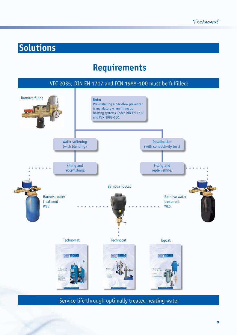
Solutions
VDI 2035, DIN EN 1717 and DIN 1988-100 must be fulfilled:
Requirements
Service life through optimally treated heating water
Water softening(with blending)
Desalination(with conductivity test)
Filling andreplenishing:
Filling andreplenishing:
Note:Pre-installing a backflow preventer is mandatory when filling up heating systems under DIN EN 1717 and DIN 1988-100.
20 Sonderausführungen auf Anfrage! Technische Änderungen vorbehalten!
Barnova FÜLL Nachfüllgruppe Einsatzbereiche: zur direkten Einspeisung von Trinkwassersysteme
in Wasserheizungs- oder Kühlwassersysteme nach DIN 1988
Aufbau Barnova Füll Kompakt : Kugelhahn, Druckminderer, Manometer und DVGW-geprüfter Systemtrenner Aufbau Barnova Füll: Kugelhahn, Wasserzähler, Schmutzfänger und DVGW-geprüfter Systemtrenner 10,0 bar / 60°C Warengruppe 90
Typ Länge (mm) Gewicht (kg) Anschluss Bestell-Nr. Preis
EURO
FÜLL Kompakt 250 1,6 G ½“ 509013 214,00
FÜLL mit Wasseruhr 680 2,4 G ½“ 509001 258,00
FÜLL mit Kontaktwasserzähler 680 2,4 G ½” 509002 319,00
Barnova FÜLL AKTIV Nachfüllstation Einsatzbereiche: zur druckkontrollierten Einspeisung in Wasserheizungs- oder Kühlwassersystemen mit MAG (z. B. Barnova HN; HT) Aufbau: Magnetventil, Druckaufnehmer, Manometer, Wasserzähler, Schmutzfänger, Absperrorgan,
DVGW-geprüfter Systemtrenner und Barnova SPS-Steuerung erforderlicher Versorgungsdruck >1,3 bar über dem MAG-Vordruck!
10,0 bar / 70°C Warengruppe 90
Typ Länge (mm) Gewicht (kg) Anschluss Bestell-Nr. Preis
EURO
FÜLL AKTIV mit Wasseruhr 680 4,4 G 1/2" 509003 1.142,00
FÜLL AKTIV mit Kontaktwasserzähler 680 4,4 G 1/2" 509004 1.229,00
Barnova FÜLL AKTIV SP Nachfüllstation Einsatzbereiche: zur druckkontrollierten Einspeisung in Wasserheizungs- oder Kühlwassersystemen mit MAG (z. B. Barnova HN; HT) Aufbau: Druckaufnehmer, Absperrorgan, Barnova SPS-Steuerung und Pumpe
erforderlicher Versorgungsdruck >1,3 bar über dem MAG-Vordruck!
Bei Einspeisung aus dem Trinkwassersystem ist Barnova FÜLL (siehe Seite 20) vorzuschalten! 10,0 bar / 70°C Warengruppe 90
Typ Länge (mm) Gewicht (kg) Anschluss Bestell-Nr. Preis
EURO
FÜLL AKTIV SP 680 14,4 G 1/2" 509012 1.390,00
Technomat Technocat Topcat
Barnova filling
Barnova water treatmentWEE
Barnova water treatmentWES
Barnova Topcat
INNOVATIVE DRUCKKOMPETENZ
Druckhaltetechnik & Entgasungstechnik
Technomat Nova /Duo Nova
✓ Druckhaltung
✓ Entgasung
✓ Nachspeisung
✓ Abspeisung
✓ Temperaturmessung
✓ Sauerstoffmessung
✓ pH-Messung
✓ Leitfähigkeitsmessung
FernüberwachungFernsteuerung
INNOVATIVE DRUCKKOMPETENZ
Druckhaltetechnik & Entgasungstechnik
Technocat TC / TC mobil
� Entgasung
� Druckhaltung
� Nachspeisung
� Temperaturmessung
� Sauerstoffmessung
INNOVATIVE DRUCKKOMPETENZ
TechnocatTC / TC mobil
Temperaturmessung
Sauerstoffmessung
Schlammabscheider & Luftabscheider
INNOVATIVE DRUCKKOMPETENZ
TechnoflexTopcat - Topcat Duo
✓ Entlüften
✓ Entschlammen
✓ Mikroblasenabscheidung
✓ Magnetische Schmutzabscheider
Topcat - Topcat Duo
Magnetische Schmutzabscheider
Schlammabscheider & Luftabscheider

10
INNOVATIVE PRESSURE COMPETENCE
Interaction of intelligent components –
from the very beginning:
Technomat –> Füll –> WE –> Topcat
The Barnova WE water softener complies
with the VDI 2035 requirements. A mem-
brane rupture signaller constantly mon-
itors the membrane operation. In the
heating up stage, the membrane collect-
ing tank takes up the expanding system
water via the relief valve (mechanical or
electrical) and makes it available again once the pump cools down.
Since the membrane separates the system water from the atmos-
phere, the talk is of an enclosed system.
The Technomat deaerates into the
non-water area of the membrane
(fizzy bottle effect) rather than
into the membrane from below and
thus against the static pressure
in the tank.
Benefit!
The Barnova Technomat Principlefeaturing high deaeration efficiency

Technomat
11
Selective setting of the pumps and relief valves can ensure that the
system pressure is kept within the Delta-P range of 0.2 bar. Deaera-
tion is undertaken by a separate solenoid valve which allows some of
the main volumetric flow of the system return to flow directly into
the non-water area of the membranes. This relief is accompanied by
separation of the gases from the system water and discharge via the
vent valve. The pump then returns the deaerated system water to the
system. This operation is repeated for as long as the interval or
constant deaeration cycles last.
The Technomat Füll or Füll K make-up feed ensures that the minimum
water level in the tank stays constant and offsets any water and
volume losses, which deaeration and leaks could be responsible for,
in a quantity-controlled manner. The point of discharging is to stop
any overfilling of the collecting tank; this is particularly important
should it not be possible to precisely determine the
system capacity.
Especially with return temperatures over
70 °C, constant temperature monitoring
of the system return flow prevents
damage and thus any costs of repair.
The effect of the set value being exceed-
ed is for automatic cooling to protect
the system.
The revolutionary oxygen measurement
in mg/l is the Barnova Technomat’s No. 1
innovation. Deaeration is only activated
once the pre-set value is exceeded.
This stops the fluid becoming so corro-
sive from uncontrolled deaeration that
it seeks to again become saturated with
gases. By consistently measuring the
water‘s pH levels and conductivity in the
system, the prescribed guideline values
are continuously kept in check.
Tip:
Entgasung einEntg
asun
g au
s Entgasung einEntg
asun
g au
s Entgasung einEntg
asun
g au
s Deaeration onDeae
rati
on of
f
Corrosion and heat loss
significantly reduced!
The ideal way to save energy
and money!

12
INNOVATIVE PRESSURE COMPETENCE
Barnova Technomat
Nova 3 to Duo Nova 8Technische DatenType
Technomat with CE Marking, constructed and tested in accordance
with EU Pressure Equipment Directive 97/23/EC and DIN EN 13831
or AD 2000. Electromagnetic compatibility pursuant to 2004/108 EC
Compliant with requirements of the Low-Voltage Directive 2006/95 EC
Areas of application
– hot water heating systems
– up to approx. 12 MW
– max. operating pressure 10.0 bar
– cooling circuit with water mixtures with
a glycol concentration of up to 50%
– pursuant to DIN EN 12828
– with temperature control > 105 °C in accordance
with Technical Rules for Steam Boilers (TRD) 604 p. 2,
EN 12952 and EN 12953
– 72 hours of unsupervised operation
– see DUO PLUS brochure
Number of pumps
Pump type
Unit type
Specifications
Tip:More information on our CD!
Electronic particulars and operating parameters
Unit NOVA3/DUO NOVA3 NOVA5/DUO NOVA5 NOVA7/DUO NOVA7 NOVA8/DUO NOVA8
Temperature range 70 70 70 70
KWNova 0.51 0.85 1.13 1.1Duo Nova 1.02 1.70 2.26 2.2
ANova 2.34 3.72 5.09 7.07Duo Nova 4.68 7.44 10.18 14.14
Max. permitted operating positive pressure (bar) 10 10 10 10
Max. holding pressure (bar) 2.2 4.4 5.6 8.5
Max. permitted operating temperature (°C) 70 70 70 70
Max. permitted supply temperature (°C) 120 120 120 120
Max. permitted ambient temperature (°C) 0 – 45 0 – 45 0 – 45 0 – 45
Noise level (approx. dB) 53 53 53 53
Degree of protection IP54 IP54 IP54 IP54
Electr. connection 230 V/50 Hz 230 V/50 Hz 230 V/50 Hz 230 V/50 Hz

Technomat
13
9
4 4
9
14 14
10 10
18
16 16
1819
19
12 12
11 11
13 1315
17 17
15
16
8 8
7 7
6 6
36
6
6
6
6
6
20
6a 6a6a
2a 2a 2a
1 1 1
2 2 2
5 5
Technomat NOVA
Technomat DUO NOVA
3 3
1: Constant pressure pump2: Relief valve (mechanical or electrical)2a: Dirt trap3: Make-up feed connection4: Deaerating valve5: Electrical control cabinet6: Capped ball valve6a: Capped ball valve with integrated return flow stopper7: System connection 1 1/2” (can be optionally used left/right)8: Supporting frame9: Membrane collecting tank
10: Pressure transmitter11: Safety valve (when SV of the heat generator > 6.0 bar)12: Solenoid valve (deaeration)13: System disconnector14: Water meter/Contact water meter15: Solenoid valve (make-up feed)16: Level detector/sensor or pressure transducer17: Ventilation and venting elbow18: Oxygen measurement point/pH measurement19: Temperature measurement point/Conductivity measurement20: Drinking water connection

14
INNOVATIVE PRESSURE COMPETENCE
DimensionsHere you find the dimensions of the diaphragm collecting tanks as basic tank and add-on tank for Barnova TECHNOMAT NOVA / DUO NOVA / DUO PLUS
Applications: - Water heating systems compliant with DIN EN 12828 - Cooling water networks
Max. operating pressure: - 6.0 barMax. diaphragm operating temperature: - 70°C Connection for NOVA/DUO NOVA: - R 1“ or R 1½“Connection for Duo Plus: - DN 80 or DN 100Basic container: - Tank equipment complete with control on the tank,
depth about 400 mm, and safety valve and ventAdd-on container: - Container equipment complete with safety valve and ventConstruction: - according to EU Pressure Equipment Directive 97/23 EG with mark
6.0 bar / 100°C / colour: blue
Type/Contents
Diameter(mm)
Height(mm)
Weight(kg)
150 550 1.351 65,0
200 550 1.568 75,0
300 550 2.001 90,0
400 750 1.685 130,0
500 750 1.917 140,0
600 750 2.150 150,0
800 750 2.615 180,0
1.000 1.000 2.111 220,0
1.250 1.000 2.437 280,0
1.600 1.250 2.276 330,0
2.000 1.250 2.608 395,0
2.500 1.250 3.024 450,0
3.000 1.600 2.505 490,0
3.500 1.600 2.759 530,0
4.000 1.600 3.012 590,0
5.000 1.600 3.520 690,0
10.000 1.600 6.710 1.180,0
We reserve the right to make technical changes and special tanks are available on request.

Technomat
15
Control SystemStandard display
Power On
· Display:
Constant pressure unit--------------------
barnova gmbhVersion X.X
Standard operation
· Display of the system pressure, tank
level and the operating states of
the pump(s) (On/Off, Manual/0/
Automatic), make-up feed/dis-
charge, deaeration and the two
relief valves
System pressure: bar Level: % P1 P2 NS GAS ÜS1 ÜS2
The switchover for Pump 1 is organ-
ized by Key 1 for Manual/0/Auto-
matic. The same applies to Pump 2
and Key 2. Malfunction or alarm is
indicated on the lowest line should
there be a fault. Continuing with
Yes.
Any fault is indicated in plain text
on the 3rd and 4th lines and can be
acknowledged. Continuing with Yes.
· Display of the temperature and
oxygen content of the heating
water should sensors be fitted
Temperature: °COxygen: mg/l
pH: Conductivity:
Continuing with Yes.
· Display of the figures of both the
pressure sensors, if two sensors are
present, and the ongoing active
sensor
Pressure s. 1: barPressure s. 2: barActive:Switchover with 1/2
Press Key 1 to switch over to Sensor
1 as the active sensor; press Key 2 to
switch over to Sensor 2. Continuing
with Key Yes.
· Display of the values of both the
level sensors, if two sensors are
present, and the ongoing active
sensor
Level s.1: % Level s.2: % Active: Switchover with 1/2
Press Key 1 to switch over to Sensor
1 as the active sensor; press Key 2 to
switch over to Sensor 2. Continuing
with Key Yes.
· Display of the pump running times
(for one or two pumps), the remain-
ing running time for the pumps and
the water meter reading (if set in
the service menu)
Pump 1: h Pump 2: h Remaining running time: m Water meter: l
Continuing with Yes.
· Display of unit and maker’s Nos.
U-number:**0000000**M-number:**0000000**
Continuing with Yes.
· Display of the service phone
numbers
barnova gmbh# Service numbers #Tel 1: 02754/21251-0Tel 2: 0171/1961237
· Display of the actual date
and time
DateTime
Change with ‘No’
Continuing with Yes, with No the
actual time can now be inputted.
· Start/Stop of constant
deaeration
The constant outflow – if not
running – can be started with
the following step (the time set
for the constant outflow is
displayed):
Constant outflowStart??
Time: h YES NO

16
INNOVATIVE PRESSURE COMPETENCE
The constant outflow – if already
running – can be stopped using the
following step. In addition, the re-
maining time of the constant outflow
is displayed:
Constant outflowin operation
Time remaining: h JA=Continue NO=Stop
Yes or No takes
you back to the
Start menu.
Altering the Parameter menuThe programming switches are in the
electrical control cabinet on the PCB
and in the standard position are at
“LEFT to TOP and RIGHT to BOTTOM”.
Switching to “LEFT to BOTTOM” gets
you to Programming Mode 1 = Op-
erator. The approach for this as well
as the scope for setting and display
of the control are as follows:
Start display
Programming mode *1* 1: Operator 2: Service 3: Malfunction memory 4: Data logger
1. Parameterization by operator (1)
without password blocking
The menus displayed are conditional
upon the settings as laid down by
Service!
· Language setting
Language: **_**0:German1:English
· Setting the static height as well as
the minimum and maximum pressure
Static height mMin.Pressure: bMax.Pressure: bmaximum: m
The 4th line has the standards for the
parameters to be currently entered
(cursor flashes)
· Setting the time delay for the fault
notification – Minimum pressure
not reached
DelaysMin.Pressure: minRange: 0..300 = no delay
· Setting the switch-on and switch-
off pressures of the basic load pump
Switch pointsBase load pumpCut-in pressure barCut-out pressure bar
· Using two pumps results in the
switch-on and switch-off pressures of
the peak load pump now being set
Switch pointsPeak load pump
Cut-in pressure barCut-out pressure bar
· Setting the delay times for the ba-
sic load pump
Delay basic load p.Switch on sec.Switch off sec.Range: 0..20 sec.
· Using two pumps results in the
delay times for the peak load pump
now being set
Delay peak load p.Switch on sec.Switch off sec.Range: 0..20 sec.
· Setting the response pressure for
deaeration (deaeration response
pressure is equivalent to the MIN
pressure)
DeaerationResponse press: bar
00.0: without deaeration
· Setting the outflow and deaeration
times

Technomat
17
· Setting whether deaeration oper-
ates as a function of time (0 = con-
stantly, 1 = as a function of time)
Deaeration time
Release 0/1
· Setting the make-up feed as a % of
the tank filling level
Make-up f.. On %Make-up f.. Off %Minimum %Maximum %
· Setting the maximum make-up
feed time
Make-up f.. On %Make-up f.. Off %Make-up f.. Time minMaximum 240 min
· Blocking the make-up feed given
non-closed relief valves
Make-up feed unobstructedwith relief valve
** **0 = No 1 = Yes
· Settings of the make-up feed for
air-conditioning operations as a %
of the tank filling level and maxi-
mum make-up feed time
Air-cond. op.Make-up f.. On %Make-up f.. Off %Make-up f.. Time min
· Settings for discharge as a % of the
tank filling level
DischargingSwitch on: %Switch off: %0 = No discharging
· When switch-on level = 0%, then
there is no discharging
· Inputting the switch-off level is
then automatically skipped
Setting conditions:
· Switch-on level must be greater
than that for make-up feed off
· The switch-on level must be
under or at the same level for
high water
· The switch-off level must be under
the switch-on level
· The switch-off level must be
greater than that for make-up
feed off
· Setting the switching pressures
for the electrical relief valves
Switch on U1 barSwitch off U1 barSwitch on U2 barSwitch off U2 bar
The switch-on pres-
sure must be between
Max-pressure and
Value for pump off!
Switching the left switch upwards
takes you to the standard display.
Then this image appears
Please wait..BNHD V00514 01.10.07
You get back to the start image.
Service menu,Password-protected
Contains all the relevant data set
at the factory and documented in
the test and acceptance inspection
record.
Memory menuPassword-protectedAll alterations in the Parameter menu
as well as warning and alarm notifica-
tions with time and date display are
documented here; the same applies
to the data logger which saves all the
operating states.
Tip:Detailed information in
the installation and oper -
ating instructions

18
INNOVATIVE PRESSURE COMPETENCE
Proportioning of the membrane collecting tank
VaVe = n ____ 100
VaVv = 0,5 ____ 100
(Ve + Vv)Vn = ____ 0,9
Va = Water content of the unit
Ve = Expansion volume
Vv = Water reservoir
Vn = Nominal capacity
Example of calculation:kW = 850
STB = 105 °C
VL = 110 °C
RL = 70 °C
Static height = 35 m
SV = 5 bar
Va not known
100% radiators
Water content of the Unit Va
with approximate values (Ltr./KW)
Heating systemsSupply temperature
70 °C 80 °C 90 °C 100 °C 110 °C
Convectors 9.5 7.5 6.0 5.0 4.0
Ventilating systems 12.5 10.0 8.0 6.5 5.5
Panel-type radiators 14.5 11.0 9.0 7.5 6.5
Radiators 22.0 17.0 13.5 11.0 9.5
Expansion coefficient
Expansion factors n in % and the evaporating pressure pD in bar positive pressure
°C n pD °C n pD °C n pD
20 0.14 - 60 1.68 - 105 4.74 0.21
30 0.40 - 70 2.25 - 110 5.16 0.50
40 0.75 - 80 2.89 - 115 5.59 0.70
50 1.18 - 90 3.58 - 120 6.03 1.00
55 1.42 - 100 4.34 - 130 6.97 1.70
Q = 850 x 0,85 = 722,50 l/h = 0,7225 m3/h
(9,5 x 850)Ve = 5,16 ___________ = 416,67 Ltr. 100
8,075Vv = 0,5 ______ = 40,38 Ltr. 100
(416,67 + 40,38)Vn = ___________ = 507,8 Ltr. 0,9
Chosen: NOVA 5-600
Special-purpose pressure appliances up to 400 MW with control unit and membrane collecting tank for temperatures
> 105 °C, for hot water installations in keeping with TRD 604 Sheet 2, EN 12952/EN 12953 for BOB 72h can be
supplied in whatever size involving individual planning according to specific customer requirements.

Technomat
19
NOVA 8
DUO NOVA 8
NOVA 7
DUO NOVA 7
NOVA 5
DUO NOVA 5
NOVA 3
DUO NOVA 3
90
80
70
60
50
40
30
20
10
0
Tip:
Selection
Calculation of the pumping capacity (Q volumetric flow) I IHeating systems: Output (kW) x 0.85 ______ = ______ hkW h
I ICooling systems: Output (kW) x 0.35 ______ = ______
Thermal output kW
Safety temperature STB °C
Supply temperature °C
Return temperature °C
Static height m
Response pressure of safety valve bar
Selection and ordering particulars
The optimum use of the Technomat Nova and Duo Nova constant
pressure stations is to be selected as a function of the p0 minimum
operating pressure, the unit’s rated thermal output and the Vn nominal
volume of the membrane collecting tank.
Whilst the minimum operating pressure determines the required
pump pressure, the thermal output does the same for the quantity
conveyed.
The nominal capacity of the membrane collecting tank is determined
by the water content of the unit and the corresponding operating
temperatures.
Characteristics – Nova/Duo NovaStatic height (m)
0 1 2 3 4 5 6 7 8 9 Q volumetric flow (m3/h)
Proportioning and design
programme on our CD

20
INNOVATIVE PRESSURE COMPETENCE
Fließschema NOVAFlow sheet - Nova
1: Constant pressure pump2: Relief valve2a: Dirt trap3: Make-up feed connection4: Deaerating valve5: Electrical control cabinet6: Capped ball valve6a: Capped ball valve with integrated return flow stopper7: System connection (can be optionally used left/right)8: Supporting frame9: Membrane collecting tank
10: Pressure transmitter11: Safety valve (when SV of the heat generator < 6.0 bar)12: Solenoid valve (deaeration)13: System disconnector14: Water meter/Contact water meter15: Solenoid valve (make-up feed)16: Level detector/sensor or pressure transducer17: Ventilation and venting elbow18: Oxygen measurement point19: Temperature measurement point20: Drinking water connection
12
4
11
49
5
15
13
14
3
2a
6
12
6a2a
7
2
5
201
SV SV SV4 4
16
10 18 19
Make-up feed waterSoftening (½” connection)
Tank Tank
Deaeration connection system return flow 3⁄8”
System return flow connection 1½”
Tank

Technomat
21
Flow sheet - Duo Nova
20
2a
3
131415
5
5
6a
12a
7
1
6
2
2
4
49
12
SV
11
SV4
10 18 19
16
Make-up feed waterSoftening (½” connection)
Tank Tank
Deaeration connection principal volumetric flow system return 3⁄8”
System return flow connection 1½”
1: Constant pressure pump2: Relief valve2a: Dirt trap3: Make-up feed connection4: Deaerating valve5: Electrical control cabinet6: Capped ball valve6a: Capped ball valve with integrated return flow stopper7: System connection (can be optionally used left/right)8: Supporting frame9: Membrane collecting tank
10: Pressure transmitter11: Safety valve (when SV of the heat generator < 6.0 bar)12: Solenoid valve (deaeration)13: System disconnector14: Water meter/Contact water meter15: Solenoid valve (make-up feed)16: Level detector/sensor or pressure transducer17: Ventilation and venting elbow18: Oxygen measurement point19: Temperature measurement point20: Drinking water connection

22
INNOVATIVE PRESSURE COMPETENCE
Notes:

Technomat
23
Notes:

Barnova GmbHHöhenweg 1657334 Bad Laasphe
Tel. 02752·4799798Fax 02752·[email protected] www.barnova.de
Branch:Barnova GmbHIm Brühl 3-757334 Bad Laasphe-Feudingen
INNOVATIVE PRESSURE COMPETENCE