Embed Size (px)
Citation preview

NOV- 4{1952 J. G. LINDEMAN ETAL 2,616,349 INTEGRAL TOOL CARRIER
Filed Sept. 17, 1948 6 Sheets-Sheet 1
INVENTORS. JESSE G.LINDEMAN, LAWRENCE F. HEINLJ
ROBERT D. KREHBIEL, ORIE L. DURLAND
v ORNEYS
Nav. 4, 1952 J. G. LINDEMAN ETAL 2,616,349 INTEGRAL TOOL CARRIER
Filed Sept. 17, 1948 _ 6 Sheets-Sheet 2
\\ F \
O '2\
V
-i 8
II)
~ & \ <r N N ‘2.
E (O (a N _ E _
(D E U.
5 Q
R
E) 0::
‘ E
if‘ R
J H" ' INVENTORS.
JESSE G. LINDEMAN, LAWRENCE E HEINL, ROBERT D. KREHBIEL, ORIE L. DURLAND
Nov. 4, 1952 J. G. LINDEMAN ETAL 2,616,349 INTEGRAL TOOL CARRIER
Filed Sept. 17. 1948 6 Sheets-Sheet 3
FIG. l3.
" INVENTORS.
' JESSE G. LINDEMAN, L. F. HEINL, ROBERT D. KREHBIEL, ORIE L. DURLAND
A ORNEYS

2,616,349 Nov. 4, 1952 J. G. LINDEMAN EI'AL INTEGRAL‘ TOOL. CARRIER
6 Sheets-Sheet 4 Filed Sept. 17, 1948
“w?
' FIG.7
4
m”? “w W
Mk, ~ 5? ///u 6,3
_ ‘ v m m m % 2 M
mm, m
7.
WW . Fm i A _ d 8 mswzrwamm
INVENTORS JESSE G. LINDEMAN, LAWRENCE F HEINL, ROBERT D. KREHBIEL, ORIE L. DURLAND
ORNEYS
Nov. 4, 1952 J. G. LINDEMAN ETAL 2,616,349 INTEGRAL TOOL CARRIER
Filed Sept. 17, 1948 6 Sheets-Sheet 5
FIG. IO
INVENTORS. JESSE G. LINDEMAN, LAWRENCE F. HEINL ROBERT D. KREHBIEL, ORIE L. DURLAND
TTORNEYS

Patented Nov. 4, 1952 2,616,349
UNITED STATES PATENT OFFICE 2,616,349
INTEGRAL TOOL CARRIER
Jesse G. Lindeman, Yakima, Lawrence F.-Heinl, Zillah, and Robert D. Krehbiel and Orie L. ‘Dur land, Yakima, Wash., assignors, by mesne as signments, to Deere & Company, Moline, 111., a corporation of Illinois
Application September 17, 1948, Serial No. 49,694
(01. 97-47) 12 Claims.
1 The present invention relates generally to agri
cultural implements and more particularly to draft devices for mounting agricultural imple ments on or connecting them to farm tractors or the like. The object and general nature of the .present
invention is the pro-vision of a new and improved , quick detachable tool carrier of the tool bar type adapted to be mounted on a farm tractor and to receive a plurality of ground working and oth er implements. A further feature of this inven tion is the provision of a tool carrier that is adapted to be controlled by the regular power lift of the tractor and a still further feature of this invention is the provision of a tool carrier which, when attached to the tractor, forms an integral part thereof and serves as means for carrying implements and the like in a compact and closely coupled arrangement, whereby the entire out?t is practically as maneuverable as the tractor alone. A further feature of this invention is the pro
vision of new and improved means, acting through the tool carrier, for adjusting the im plement depth, the amount and degree of suc tion of earth working tools, and the lateral or transverse leveling of the implements. it is a feature of this invention to provide a tool carrier of the type which may be adjusted to ac commodate free lateral movement of the tool carried by the carrier or the parts may bear ran-ged so that the implement may be locked in place laterally, as for transporting or when op erating tools where a laterally rigid hitch is de sired. ‘
These and other objects and advantages of the present invention will be apparent to those skilled in the art after a consideration of the following detailed description of the preferred structure, taken in conjunction with the accompanying drawings. In the drawings: Figure l is a side view and Figure 2 is a rear
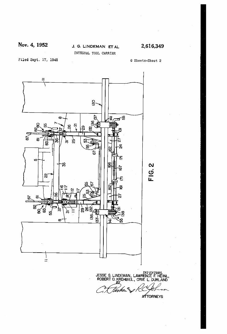
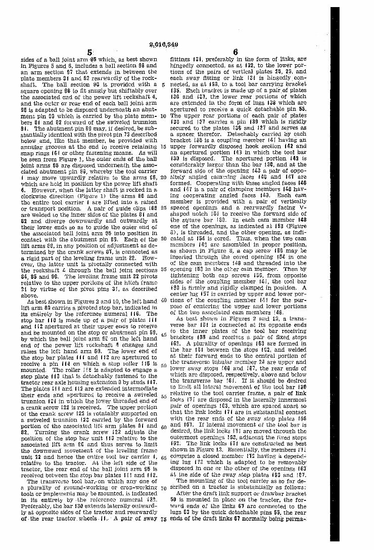
view of the preferred form of tractor-carried or integral tool carrier, shown as mounted on a tractor. of the type having a power lift including a rear transverse power lift rockshaft. Figure 3 is a fragmentary sectional view taken
along the line 3—3 of Figure 1, showing the ball and socket type of connection between the front and rear ends'of the laterally spaced lower draft links and the tractor and tool carrier hitch frame. I
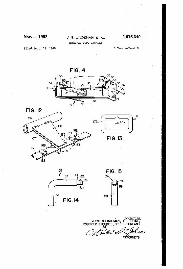
Figure 4 is a fragmentary perspective view of the drawbar bracket or draft link support and
Further, V
10
15
25
30
35
40
45
50
65
its connection to the tractor and the tractor drawbar support. Figure 5 is a partial or fragmentary plan view
of power lift arm or upper link connection be tween the tool carrier hitch frame and the trac tor power lift rockshaft. Figures 6 and 7 are sectional views taken, re
spectively, on ‘the lines 6—-6 and ‘l—--‘! of Figure 5, the ball joint arm being omitted in Figure 7,. Figures 8 and 9 are section-a1 views taken re
spectively along the lines 8-8 and 9--9 of Fig ure 1, showing the preferred form of tool bar mounting. _
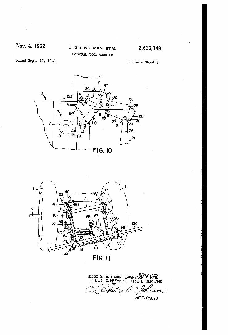
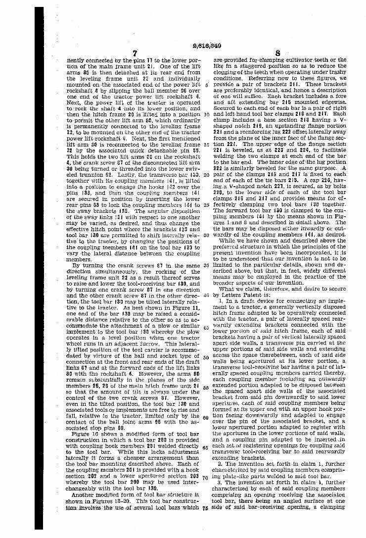
Figure 10 is a fragmentary side view showing the adjustable stop means limiting the lower po sition of the tool carrier. Figure 11 is a fragmentary perspective view
showing the too-l carrier adjusted for operating with the tool bar in a laterally tilted position, as may be desirable when using a plow attachment, with the right hand rear tractor wheel operat ing in a previously formed furrow. Figure 12 is a fragmentary view showing the
means for limiting the lateral movement of the tool bar relative to the hitch frame. Figure 13 is a detail perspective of one of the
stop members shown in Figure 12. Figures 14 and 15 are side and end views, re
spectively, of one of the quick detachable pins employed for connecting the tool carrier with the tractor. '
Figures 16 and 17 are plan and side views of a modi?ed form of tool bar.
Figures 18, 19 and 20 are plan, side and rear views of another form of tool bar construction.
Referring ?rst to Figures 1 and 2, the draft de vice of the present invention shown as a tool carrier, indicated in its entirety by the reference numeral I, mounted on a tractor 2 of the type having a controllable power lift unit 3 which is arranged to operate a transverse power lift rock shaft 4, the ends of which extend from opposite sides of a power lift rockshaft housing 5. The tractor and power lift is conventional, so far as the present invention is concerned, and may be similar to that shown in U. S. Patent 2,302,637, issued November 17, 1942, to E. McCormick, et al. The tractor 2 includes a rear axle housing 1 in lateral extensions 8 of which are axle shafts 9 on which rear traction wheels II are mounted. The lower portion of the rear axle housing ‘I, centrally of the tractor, carries a drawbar sup port l2 in which a laterally swingable dnawbar l3v is disposed. The draft device or tool carrier I includes a
2,616,349 3
generally vertically disposed rigid hitch frame 20 which comprises a lower main frame unit 2i and an upper rigid leveling frame 22. As best shown in Figures 2 and 11, the lower frame unit 21 comprises a rigid frame section made up of a lower transverse tubular member 213 to each end, of which a pair of vertical, closely spaced frame plates 25 and 23 are connected, as by weld ing or the like. Gusset plates 27 are welded to the inner plates 25 and the end portions of the transverse tubular member 2d. Each pair of plates 25 and 26 is rigidly interconnected by one or more spacers 29, and the upper ends of the frame plates 25 and 255 are apertured to receive a pivot pin 3!. The leveling frame unit 22 comprises a rigid
structure made up of a transverse tubular meme ber 35 to each end of which is rigidly connected, as by welding, a pair of closely spaced plates 3% and 31, the spacing between the plates being such that they ?t snugly between the upper portions of themain frame plates 25 and 26, as best shown in Figure 2. The lower rear portions of the plates 35 and 37 are provided with a pair of apertures 39 adapted to receive the associated pivot pin 3| and provided for two positions of the latter, as best shown in Figure l. The pins 3! and asso ciated parts provide a hinged connection be tween the mainframe unit 24 and the leveling framekunit 22 whereby one part is constrained to move relative to the other about a transverse hinge axis, as de?ned by the pins 3!. The latter may be of any suitable construction but prefer ably are relatively short cylindrical _ members having grooves at the end portions to receive snap rings Lil (Figure 10), which detachably hold theassociated parts in assembled relation. A draftlink support in the form of a drawbar
bracket 5L9 is adapted to be secured by a plurality of bolts 5i and 52 to the tractor drawbar sup port 12. The drawbar brackettii includes pairs of upstanding lugs 53, each provided with a pair of apertures 51% by which each pair of lugs is adapted to receive aquick detachable pin 55 in either of two optional positions. The construc tion of the pins 55 is best shown in Figures 14 and 15,’ Each pin includes a shaft portion 57! and a handle portion 58, the shaft portion beinginsert able through the openings in the lugs and/or other parts torreceive it. Theend of. the shaft section 57 is slabbed off, as shown at 59, tapered at its outer end, as shown at 63, and is provided with an annular groove 6! which lies between a cylindrical portion 62. and the main body of the shaft section 5?. The slabbed off portion 59 lies at the side adjacent the handle 58 and is thus ar ranged so that the pin may be inserted inopen ings arranged to fit the shaft section 51 with the exception that one of the inner openings, .as the opening in the inner lug portion 53, is provided with an inwardly directed section 63 which is circularly complementary with respect to the slabbed off portion 59. Thus, when the pin 55 is turned to bring the handle section 58 upwardly and inserted in that position in the openings, the slabbed oif portion 59 receives the inner section 63, and then when the handle section 58 is. turned downwardly, the portion 63 interlocks in the groove GI and prevents accidental disconnection of the pin 55. The bolt 52 serves also to pivotally interconnect the tractor drawbar [3 with the tractor drawbar support l2. Ordinarily, the drawbar bracket 59 is left as a more or less per manent part of the tractor, even when the in tegral tool carrier 1 of the present invention is
10
15
25
30
35
40
55
70
76
4 disconnected from the tractor to provide for other uses of the latter. The lower portion of the tool carrier hitch
frame 25 is connected with the drawbar bracket 56 by link means which not only transmits the draft of the tools to the tractor but also provides for not only up and down movement of the hitch frame 29 but also lateral swinging and oscilla tion with respect to the tractor. Referring now more particularly to Figures 1-K}, a pair of lower links 67 extends ‘between the tractor and the lower portion of the hitch frame 2G. Each link 51 includes an. enlarged apertured end portion 68, the sides 69 of which are flanged and embrace a spherical bushing ‘ii, the aperture '52 of which is dimensioned to ?t snugly over the associated pivot pin. In order to hold the bushing ll in place, the ?anges 69 are crimped so as to snugly embrace the outer spherical surface of the asso ciated bushing "ii; The front end bushings‘?! receive the shaft sections 5? of the associated quick detachable pins 55, and as best shown in‘ Figure 3, the rear end of each of the links 61 is connected through the associated bushing H with a pivot pin ‘l3 that extends through apertures 74 in the lower portions of the associated hitch frame plates 25 and 26. Each end of each pin 73 is grooved to receive a detachable snap ring ‘H, the rings ll’ holding the pivot pins '53 in place but permitting their ready removal when desired. The hitch pin ‘53 and associated parts may be substantially identical with the connecting pin 3! mentioned above. A pair of upper link members, each indicated
in its entirety by the reference numeral 80, con nects the leveling frame unit 22 of the hitch frame 29 with the tractor 2. Preferably this connection is made through the tractor power lift rockshaft 4 and the link members 86 are arranged to be so connected with the power lift rockshaft 4 as to serve as lift arms for raising the hitch frame 29 and associated tool-receiving bar and the tools connected therewith. Each link or power lift arm 88 comprises two plates 8! and 82 rigidly inter connected by a spacer 83 and an arcuate part 84 which partially encircles and is concentric with respect to openings 85 in the forward ends of the plates 8! and 82. The rear ends of each pair of plates 8! and 82 are pivotally connected with the associated pair of plates 36 andv 37 of the leveling frame unit 22, by a quick detachable hitch pin that is identical with the hitch pin 55 described above. Thus, the last mentioned hitch pins es tablish a transverse axis about which the right and left hand links, or arm members 80 are hingedly connected with the leveling frame unit 22 but relative movement between the parts in any other direction is restrained, not only by the hinged connection but also by the fact that the leveling frame plates 35 and 3‘! snugly fit within the lift arm plates SI and 82, as best shown in Figure 2. While we have shown both connec tions as established through a quick detachable pin 55, only one need be quick detachable. The other may be a pin like that shown in Figure 3. Each arm 86 is adjustable relative to the adjacent portion of the leveling frame 22 by means of a crank screw 81 which is provided with oppositely threaded portions 88 and 89 received in swiveled trunnions 9i and 92 carried, respectively, ‘by the plates BI, 82 and 36, 31, the members 9! and 92 I having screw-threaded openings to receive the crank screw portions 38 and 89. The forward end portions of the lifting ar'm'
plate members BI and 82 are disposed on opposite
6:349 5;
sides of a ball joint arm 95 which, as best shown in Figures 5 and 6, includes a ball section 96 and an arm section 8? that extends in between the plate members 8! and 82 rearwardly of the rock shaft. The ball section at is provided with a square opening 98 to ?t snugly but shiftably over the associated end of the power lift rockshaft Q, and the outer or rear end of each ball joint arm 95 is adapted to be disposed underneath an abut ment pin 99 which is carried by the plate mem bers BI and 82 forward of the swiveled trunnion 9 I. The abutment pin $9 may, if desired, be sub stantially identical with the pivot pin ‘I3 described below and, like that member, be provided with annular grooves at the end to receive retaining snap rings IQI or other fastening means. As will be seen from Figure 1, the outer ends of the ball joint arms 95 are disposed underneath the asso ciated abutment pin 99, whereby the tool carrier I may move upwardly relative to the arms 95, which are held in position by the power lift shaft 4. However, when the latter shaft is rocked in a clockwise direction (Figure 1) the arms 88 and the entire tool carrier I are lifted into a raised or transport position. A pair of guide clips I133 are welded to the inner sides of the plates BI and 82 and diverge downwardly and outwardly at their lower ends so as to guide the outer end of the associated ball joint arm 95 into position in contact with the abutment pin 99. Each of the lift arms as, in any position of adjustment as de termined by the crank screws 8?, is connected as a rigid part of the leveling frame unit 22. How ever, the latter unit is pivotally connected with the rockshaft It through the ball joint sections 84, 85 and 93. The leveling frame unit 22 pivots relative to the upper portions of the hitch frame 2I by virtue of the pivot pins 3i, as described above. As best shown in Figures 2 and 10, the left hand
lift arm 80 carries a pivoted stop bar, indicated in its entirety by the reference numeral HQ. The stop bar IIG is made up of a pair of plates HI and H2 apertured at their upper ends to receive and be mounted on the stop or abutment pin 99, by which the ball joint arm ti; on the left hand end of the power lift rockshaft 4 engages and raises the left hand arm 85. The lower end of the stop bar plates III and H2 are apertured to receive a pin lid on which a stop roller H5 is mounted. The roller I55 is adapted to engage a stop plate H6 that is detachably fastened to the tractor rear axle housing extension 8 by studs I II. The plates II I and H2 are extended intermediate their ends and apertured to receive a swiveled trunnion I2I in which the lower threaded end of a crank screw I22 is received. The upper portion of the crank screw £22 is rotatably supported on a swiveled trunnion I23 carried by the forward portion of the associated lift arm plates BI and 82. Turning the crank screw 122 adjusts the position of the stop bar unit iIii relative to the associated lift arm 88 and thus serves to limit the downward movement of the leveling frame unit 22 and hence the entire tool bar-carrier I, relative to the tractor. At the'left side of the tractor, the rear end of the ball joint arm 95 is received between the stop bar plates I I I and I I2. The transverse tool bar,‘ on which any one of
a plurality of ground-working or crop-working tools or implements may be mounted, is indicated in its entirety by the reference numeral I39. Preferably, the bar 933 extends laterally outward 1y at opposite sides of the tractor andrearwardly of the rear tractorwheelsIL- ' Apairof sway
15
25
30
40
60
65
70
75
6 ?ttings I3I, preferably in the form of links, are hingedly connected, as at I32, to the lower por tions of the pairs of vertical plates 25, 2E, and each sway ?tting or vlink I3I is hingedly con nected, as at I33, to a tool bar carrying bracket I35. Each bracket is made up of a pair of plates I36 and I31, the lower rear portions of which are extended in the form of lugs I38 which are apertured to receive a quick detachable pin 55. The upper rear portions of each pair of plates i323 and i3? carries a pin I39 which is rigidly secured to the plates I36 and I3?‘ and serves as a spacer therefor. Detachably carried by each bracket I35 is a coupling member IQI having an upper forwardly disposed hook section M2 and an apertured portion I53 in which the tool bar I36 is disposed. The apertured portion I43 is considerably larger than the bar I30, and at the forward side of the opening M3 a pair of oppo sitely angled camming faces I136 and Isl are formed. Cooperating with these angled faces I135 and Hill is a pair of clamping members I48 hav ing cooperating angled faces I49. Each cam member is provided with a pair of vertically spaced openings and a rearwardly facing V shaped notch i5I to receive the forward side of the square bar I353. In each cam member I48 one of the openings, as indicated at I53 (Figure 8), is threaded, and the other opening, as indi cated at its is cored. Thus, when the two cam members I438 are assembled in proper position, as shown in Figure 8, a cap screw I56 may be inserted through the cored opening Iiili in one of the cam members ids and threaded into the opening I53 in the other cam member. Then by tightening both cap screws I56, from opposite sides of the coupling member Mi, the tool bar we is ?rmly and rigidly clamped in position. A center lug i5"! is carried by upper and lower por tions of the coupling member IQiI for the pur pose of centering the upper and lower portions of the two associated cam members I138. As best shown in Figures 2 and 12, a trans
verse bar IBi is connected at its opposite ends to the inner plates of the tool bar receiving brackets I35 and receives a pair of ?xed stops IE2. A plurality of openings 563 are formed in the bar iGI between the stops I62, and welded at their forward ends to the central portion of the transverse tubular member ‘25 are upper and lower sway stops Hit‘ and Isl, the rear ends of which are disposed, respectively, above and below the-transverse bar ItI. If it should be desired to limit all lateral movement of the tool bar I39 relative to the tool carrier frame, a pair of link locks iii are disposed in the laterally innermost pair of openings IE3, which are spaced apart so that the link locks iii are in substantial contact with the rear ends of the sway stop plates I36 and NW. If lateral movement of the tool bar is desired, the link locks Iii are moved'through the outermost openings I53, adjacent the fixed stops I62. The link locks Iii are constructed as best shown in Figure 13. lssentially, the members H’ l‘ comprise a closed member I72 having a depend ing lug I18 which is adapted to be removably' disposed in one or the other of the openings I63’ at the side of the sway stop plates I66 and IE1‘.
‘ The mounting of the tool carrier as'so far de— scribed on a tractor is substantially as follows:
After the draft link support or drawbar bracket 5Q is mounted in place on the tractor, the for ward ends of the links 61 are connected to ‘the lugs 53 by the quick detachable pins 55, the rear ends of the draft links 61 normally being pe'rma-zr
2613,5349
n'ently‘connected by the pins 1‘! to the lower por tion of ‘the main frame unit 2'I. One of the lift arms '80 is then detached at its rear end from the leveling frame unit 22 and individually mounted on the associated end of the power lift rockshaft 1; by slipping the ball member at over one ‘end of the tractor power lift rockshaft 5. Next, the power lift of the tractor is operated to rock the shaft 4 into its lower position, and then the hitch frame 26 is lifted into a position to permit the other lift arm 83, which ordinarily is permanently connected to the leveling frame 22, to be mounted on the other end of the tractor power-liftrockshaft 5. Next, the ?rst mentioned lift arm 83 is reconnected to the leveling frame 22 by the associated quick detachable pin 55. This'holds the two lift arms 83 on the rockshaft 4, the crank screws? of the disconnected lift arm 38 being‘turned or threaded into the lower swiv eled trunnion 92. Lastly, the transverse bar I33, together with its coupling members idi, is lifted into a position to engage the hooks I532 over the - pins I39, and then the coupling members MI are secured in position by inserting the lower rear pins 55 to lock the coupling members ltil to the sway brackets I35. The angular disposition of the sway links I3l with respect to one another may be varied, as desired, and thus change the effective hitch point where the brackets I35 and tool bar I30 are permitted to shift laterally rela tive to‘the tractor, by changing the positions of the coupling members I4! on the tool bar I38 to vary the lateral distance between the coupling members. By turning the crank screws I5‘! in the same
direction simultaneously, the rocking of the leveling frame unit 22 as a result thereof serves to raise and lower the tool-receiving bar I 30, and by turning one crank screw 81 in one direction and the other crank screw 8'! in the other direc tion, the tool bar I36 may be tilted laterally rela tive to the tractor. As best shown in Figure 11, one end of the bar I30 may be raised a consid erable distance relative to the other so as to ac commodate the attachment of a plow or similar implement to the tool bar I36 whereby the plow operates in a level position when one tractor wheel runs in an adjacent furrow. This lateral ly tilted position of the tool carrier is accommo dated by virture of the ball and socket type of connection at the front and rear ends of the draft links Gland at the forward ends of the lift links 80 with the rockshaft 4. However, the arms 89 remain substantially in the planes of the side members 25, 26 of the main hitch frame unit 2I so- that the amount of tilt is always under the control of the two crank screws 81. However, even in the tilted position, the tool bar l3!) and associated toolsor implements are free to rise and fall, relative to the tractor, limited only by the contact of the ball joint arms 95 with the as sociated stop pins 99.
Figure 16 shows a modi?ed form of tool bar construction in which a tool bar 200 is provided with coupling hook members 2!“ welded directly to the tool bar. While this lacks adjustment laterally it forms a cheaper arrangement than the tool bar mounting described above. Each of the coupling members 20 I is provided with a. hook section 202 and a lower apertured section 293 whereby the tool bar 200 may be used inter changeably with the tool bar I39. Another modi?ed form of tool bar structure is
shown inFigures 18-20. This tool bar construc tiondnvolves the :use inf several .tool bars ‘which
20
35
45
50
55
60
65
70
75
8. are provided for-clamping cultivator ‘teeth or the like in a staggered 3position so as to reduce the cloggingv of the teeth when operating under trashy conditions. Referring vnow to these ?gures, we provide a pair of brackets -2I-I. These brackets are preferably identical, and hence a'description of one will suffice. Each bracket includes a fore and aft extending bar 215 mounted edgewise. Secured to each-‘end of each bar is a pair of right and left hand tool barclamps 2I6and 2H. Each. clamp includes a base section -2I8 having a V shaped notch .2I9, an upstanding ?ange portion 22I and ‘a reenforcing lug 222 offset laterally away from theplane of the inner face of the ?ange sec tion. ‘22I. The upper edge of the ?ange section ‘22I isybeveled, as at 223 and 224, to facilitate welding the two clamps at each endof the bar to the bar end. The inneredge of the lugportion 222 is similarly beveled for'thevsame purpose. :A pair of the clamps 2I6 and 2I'I is ?xed to each end of each of the tiebars2I5. A cap 226, hav ing a V-shaped notch 2'2'L'is secured, as by bolts 228, to the vlower side of each of the tool bar clamps52l6 and .2I.‘I and. provides means for ef fectively clamping two tool bars I39 together. The forward tool bar I3? is clamped to the cou pling members I'M by the means shown in Fig ures Land 8 and described in detail above. The tie bars may be disposedeither inwardly or out wardly of‘the coupling members Idl, as desired. While we have shown and described above the
preferred structure in which the principles of the present invention have ‘been incorporated, it :is to be understood that our ‘invention is not to be limited to the particular'details, shown and de scribed above, but that, in fact, widely different means may be employed in the practice of the broader aspects of ‘our invention. What We claim, therefore, and desire to- secure
by ‘Letters Patent is: 1, In a draft device for connecting an imple
ment to .a tractor, a generally vertically disposed hitch frame adapted to be operatively connected with the tractor, a pair of laterally spaced rear wardly extending brackets connected with the lower portion of said hitch frame, each of said brackets having a pair of vertical laterally spaced apart side walls, a transverse ,pin carried at the upper portions of said side walls and extending across the space therebetween, each of said side walls being apertured at its lower portion, a transverse tool-receiving bar having a pair of lat erally spaced coupling members carried thereby, each coupling member including an outwardly extended portion adapted to be disposed between the spaced apart side walls of the associated bracket from said pin downwardly to said lower apertures, each of said coupling members being formed at its upper end with an upper hookpor tion facing downwardly and adapted to engage over the pin of the associated bracket, and a lower apertured portion adapted to register with the apertures in the lower portions of said walls, and a coupling pin adapted to be insertedin each set of registering openings fOr coupling said transverse tool-receiving bar to said rearwardly extending brackets.
2. The invention set forth in claim 1, further characterized by said coupling members compris ing plate-like parts welded to said tool bar.
3. The invention set forth in claim 1, further characterized by each of said coupling members comprising an opening receiving the associated tool bar, there being an angled surface at one side ‘of said bar-receiving opening, a clamping
2,616,349 91'
member having a complementarily formed, an gled camming surface adapted to ?t against said angled surface, and means for moving said clamping member along said angled surface for clamping the tool bar in said coupling member.
4. The invention set forth in claim 3, further characterized by a pair of oppositely arranged angled surfaces on said coupling member, and a pair of clamping members having complemen tarily formed angled surfaces, and means acting between said clamping members for moving them along said angled surfaces and clamping said tool bar in said coupling member.
5. In an agricultural implement, a sup-port, a pair of laterally spaced rearwardly extending brackets connected with said support, each of said brackets having an upper portion carrying a pin and a lower apertured portion disposed sub stantially underneath said pin, a transverse tool receiving bar having a pair of laterally spaced coupling members carried thereby, each coupling member including an upper extension formed with a downwardly extending hook portion adapted to engage over the pin of the associated bracket with the pin lying between the forward edge of the coupling member and the down vardly extending hook portion, whereby said cou pling members and tool-receiving bar may be supported temporarily on said bracket-carried pins, and a lower apertured portion adapted to register with the aperture in the associated bracket, and a coupling pin adapted to be in serted in each pair of registering openings for coupling said transverse tool-receiving bar to said rearwardly extending brackets.
6. In a draft device for connecting an imple ment to a support, a tool bar member, a coupling member having a portion receiving and embrac ing said tool bar member, said coupling member having at one side of said portion a pair of oppo sitely angled surfaces, a pair of clamping mem bers having complementarily formed angled sur faces adapted to engage, respectively, said ?rst mentioned angled surface, the opposite portions of said clamping members being shaped to en gage said tool bar member, and means acting be tween said clamping members for moving them toward one another along said ?rst angled sur faces and clamping said tool bar in said coupling member.
7. In an agricultural implement, a support, a pair of laterally spaced brackets connected with said support, each of said brackets having an upper portion carrying a pin and a lower aper tured portion disposed substantially underneath said pin, a transverse tool-receiving bar having a pair of laterally spaced coupling members car ried thereby, each coupling member including an upper extension formed with a downwardly ex tending hook portion adapted to engage over the pin of the associated bracket with the pin lying between the adjacent edge of the coupling mem ber and the downwardly extending hook portion, whereby said coupling members and tool-receiv ing bar may be supported temporarily on said bracket-carried pins, and a lower apertured por tion adapted to register with the aperture in the associated bracket, and a coupling pin adapted to be inserted in each pair of registering openings for coupling said transverse tool-receiving bar to said brackets.
8. For use with a draft device for connecting an implement to a support, which device includes a pair of brackets connected with said support, each of said brackets having an upper portion
10
15
20
25
35
40
45
50
55
60
65
70
75
lb carrying a pin and a'lower apertured portion dis posed substantially underneath said pin: the im provement comprising a transverse tool-receiving bar having a pair of laterally spaced coupling members carried thereby, each coupling member including an upper extension formed with a downwardly extending hook portion adapted to engage over the pin of the associated bracket with the pin lying between the adjacent edge of the coupling member and the downwardly extending hook portion, whereby said coupling members and tool-receiving bar may be supported tempo rarily on said bracket-carried pins, and a lower apertured portion adapted to register with the aperture in the associated bracket, said lower apertured portion being spaced in a fore-and aft direction from the associated hook portion a distance such that when the hook portion is en gaged over the associated‘bracket pin, the aper ture in said apertured portion registers with the associated bracket aperture.
9. In a draft device for connecting an imple ment to a tractor, a pair of laterally spaced apart, draft-transmitting brackets, each of said brack ets having a pair of vertical laterally spaced apart side walls, a transverse pin carried at the upper portions of said side walls and extending across the space therebetween, each of said side walls being apertured at its lower portion, a tool support having a pair of laterally spaced coupling members carried thereby, the lateral spacing of said coupling members corresponding to the lat eral spacing of said brackets, each coupling mem ber including an outwardly extended portion adapted to be disposed between the spaced apart side walls of the associated bracket from said pin downwardly to said lower apertures, each of said coupling members being formed at its upper end with an upper hook portion facing downwardly and adapted to engage over the pin of the asso ciated bracket, and a lower apertured portion adapted to register with the apertures in the lower portions of said walls, and a coupling pin adapted to be inserted in each set of registering openings for coupling said transverse tool-re ceiving bar to said rearwardly extending brackets.
10. A coupling member for supporting a tool bar or the like, said coupling member comprising a part having an opening to receive said tool bar, there being a pair of oppositely angled sur faces at one side of said bar-receiving opening, a pair of clamping members having complemen tarily formed, angled camming surfaces adapted to fit, respectively, against said angled surfaces, and means for moving said clamping members toward one another along said angled surfaces for clamping the tool bar in said part.
11. A coupling member for connecting a tool bar with a supporting bracket, said coupling member comprising a part having an opening to receive said tool bar, there being a pair of oppo sitely arranged angled surfaces on said part, and a pair of clamping members having complemen tarily formed angled surfaces, means acting between said clamping members for moving them along said angled surfaces and clamping said tool bar in the opening in said part, and means on said coupling member for connecting the latter to said bracket.
12. For use with an agricultural implement having a support and a pair of laterally spaced brackets connected with said support, each of said brackets having an upper portion carrying a pin and a lower apertured portion disposed substantially underneath said pin, the improve"

2516,3149 II
ment comprising a‘ tool-receiving member, . aipa-ir of: laterally spaced, coupling members carried thereby, each coupling ‘member including‘ an upper‘ extension formed with, a downwardly extending hock portion adapted to. engage over the pin of the associated bracket with the pin lying‘ between the adjacent edge of the coupling member and the downwardly extending hook portion, whereby said coupling members and tool-receiving bar may be supported temporarily on said bracket-carried pins, and a lower aper tured'por'ti'on adapted" to register with theaper ture inrthe associated“ bracket, and a coupling pin adapted to be inserted in each pair of‘registering openings for coupling said tool-receiving'member to said brackets.
JESSE G. LINDEMAN.‘
LAWRENCE F5 ‘ROBERT-"D. KREI-IBIEL.
ORIE'. L. DURLAND.
REFERENCES CITED The following references are of record in the
?le of‘ this patent’:
Number 163,406 612,046
5 359,741 1,006,974 1,227,219 1,337,391 2,129,746
10 2,174,806 2,262,546 2,302,637 2,342,309
_ 2,346,330
15 2,402,003 2,430,732
Number 2° 496,131
1'2 UNITED STATES.‘ PATENTS:
Name Date Ober ______________ __ Oct. 5, 1875
Miller et a1 ________ __ Oct. 111, 1898 Graham __________ __ Oct. 16, I909 Mooreet a1 _______ __ Oct. 24, 1911 Thyseli- __________ __ May 22, 1917
C0oper>__________._-,_ Apr‘. 20, 1926 Smith ___________ __ Sept. 13, 1938
Tuft _______________ _, Oct. 3, 11939
Donoho et'al ______ __ Nov. 11‘, 1941 McCormick et a1. ____ Nov. 17, 1942 Silver ______________ _, Feb. 22, 1944
Ratcli?f __________ __ Apr. 11-, 1944
Ariens ___________ __ June 11,1946
O-relind et a1; _____2,_ ‘Nov. 11,1947
FOREIGN‘ PATENTS
Country Date. France ___________ __ Ju1y'24, 1919
France ___________ __ Oct. 29, 1926 616,484


![Henry Lindeman - Method for Saxophone[1]](https://img.dokumen.tips/doc/110x75/5571f32149795947648d8c23/henry-lindeman-method-for-saxophone1.jpg)