Embed Size (px)
Citation preview

Feasibility Studies for the Proposed Extension of Navigational Channel at Mazagon Dock, Mumbai C
[Type the document subtitle]
Final Report
Nov
2016
WAPCOS Limited
Pune
Mazagon Dock Limited

Feasibility Studies for the Proposed Extension of Navigational Channel at Mazagaon Dock, Mumbai
Final Report Page i
TABLE OF CONTENTS
No. PARTICULARS Pg. No.
Executive Summary i
Chapter 1 : Introduction
1.0 Introduction 1
1.1 Brief History 3
1.2 Scope of Work 5
1.2.1 Objective of the Study 5
1.3 Organisation of the Report 5
Chapter 2 : Site Condition
2.1 Site Condition 6
2.2 Bathymetry 6
2.3 Wind 7
2.3.1 Offshore Wind Data 7
2.3.2 Inshore Wind Data 7
2.4 Tides 8
2.5 Current 8
2.6 Wave 9
2.7 Relative Humidity 9
2.8 Temperature and Salinity 9
2.9 Rainfall 10
2.10 Bed and Water Samples 10
Chapter 3 : Field Survey and Investigation
3.1 General 11
3.2 Bathymetry 11
3.3 Field Data Collection for Monsoon Season 12
3.3.1 Tides 12
3.3.2 Current 14

Feasibility Studies for the Proposed Extension of Navigational Channel at Mazagaon Dock, Mumbai
Final Report Page ii
3.3.3 Water Sample 14
3.4 Field Data Collection for Non-Monsoon Season 15
3.4.1 Tides 15
3.4.2 Current 16
3.4.3 Water Sample 16
3.4.4 Bed Sample 16
3.5 Comparison of Monsoon with Non-Monsoon Observations
17
3.5.1 Tide 17
3.5.2 Currents 17
3.6 Geotechnical Investigation 19
3.7 Laboratory Test 21
3.8 Test on Soil Samples 22
3.9 Test on Rock Samples 22
3.10 Test on Water Samples 22
3.11 Exploration Program 22
3.12 Subsurface Profile 23
Chapter 4 : Mathematical Model Studies carried out at CWPRS, Pune
4.1 General 25
4.2 Mathematical Model Studies for Hydrodynamics and Siltation
25
4.2.1 Recommendations by CWPRS 26
4.3
Mathematical Model Studies for Wave Transformation and Assessment of Wave Condition along Proposed Extension of Navigational Channel
27
4.3.1 Recommendations by CWPRS 28
4.4 Desk Studies for Design of Proposed Extension of Navigational Channel
29
4.4.1 Recommendations by CWPRS 29
4.5 Mathematical Model Studies to Assess Feasibility of Flood Dumping Ground for Disposal of Dredged Material
30
4.5.1 Recommendations by CWPRS 31

Feasibility Studies for the Proposed Extension of Navigational Channel at Mazagaon Dock, Mumbai
Final Report Page iii
4.6 Seismic Sub Bottom Profile Studies 31
4.6.1 Conclusions made by CWPRS 32
Chapter 5 : Budgetary Cost
5.1 Basis of Cost Estimates 33
5.1.1 Dredgers 33
5.1.2 Methodology 34
5.1.3 Disposal of Dredged Material 34
5.1.4 Maintenance Dredging 34
5.2 Basis of Cost Estimates 34
5.3 Calculation of Cost Estimate 35
Chapter 6 : Concluding Remarks & Recommendations

Feasibility Studies for the Proposed Extension of Navigational Channel at Mazagaon Dock, Mumbai
Final Report Page i
LIST OF FIGURES
No. PARTICULARS Pg. No.
Figure A Proposed Layouts of Navigational Channel from MDL up to OCT Berth (Option I and Option II)
iv
Figure B Proposed Layout of Navigational Channel from MDL to OCT Berth – Option III
iv
Figure 1.1 Location Plan of Mazgaon Dock Shipyard at Mumbai
1
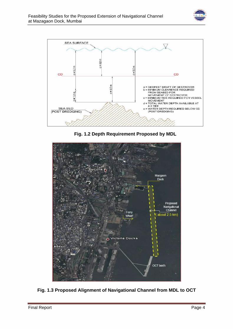
Figure 1.2 Depth Requirement Proposed by MDL 4
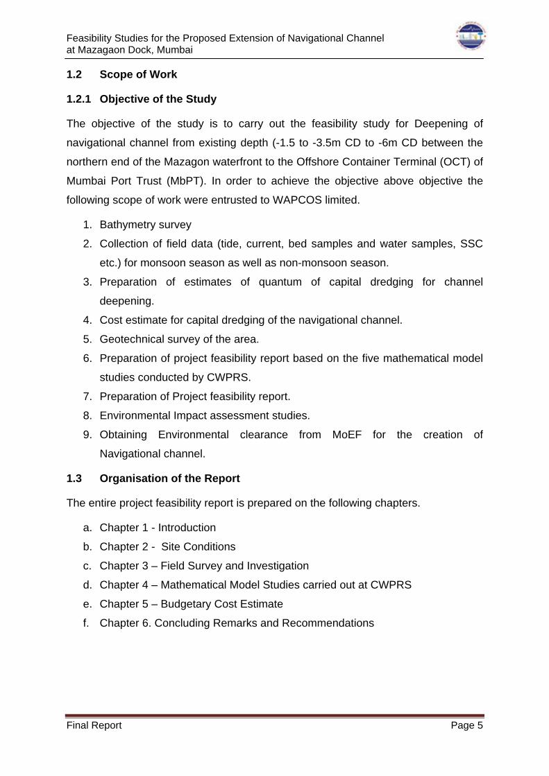
Figure 1.3 Proposed Alignment of Navigational Channel from MDL to OCT
4
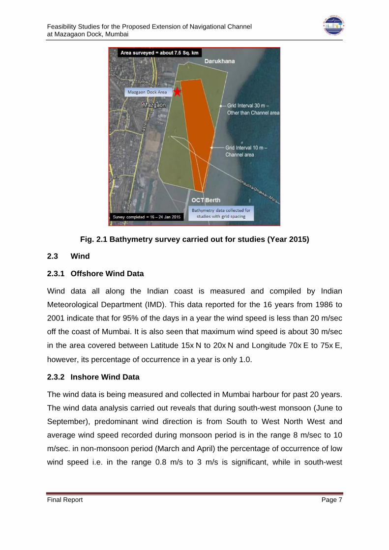
Figure 2.1 Bathymetry survey carried out for studies (Year 2015)
7
Figure 3.1 Bathymetry Survey carried out for Studies (Year 2015)
12
Figure 3.2 Tide graph at MbPT, Ambuja, Vashi and Rewas during springs
13
Figure 3.3 Tide graph at BPX- MbPT, Ambuja Jetty, Vashi Bridge and Rewas Jetty during springs
14
Figure 3.4 Locations of Marine Boreholes (BH-1 to BH-08) 15
Figure 3.5 Locations of Marine Boreholes (BH-1 to BH-08) 20
Figure 4.1 The final layout confirmed by CWPRS through hydrodynamic and siltation studies
27
Figure 6.1 Final layout recommended by CWPRS 36
Figure 6.2 Locations of dumping sites off Mumbai harbour 38

Feasibility Studies for the Proposed Extension of Navigational Channel at Mazagaon Dock, Mumbai
Final Report Page i
LIST OF TABLES
No. PARTICULARS Pg. No.
Table 2.1 Tidal Levels 8
Table 3.1 Tidal ranges at MbPT, Ambuja, Vashi and Rewas Locations
13
Table 3.2 Comparison of Tidal ranges during non-monsoon and monsoon Period
17
Table 3.3 Comparison of Ebb current during non-monsoon & monsoon period at location C1
17
Table 3.4 Comparison of Flood current during non-monsoon and monsoon period at location C1
18
Table 3.5 Comparison of Ebb current during non-monsoon & monsoon period at location C2
18
Table 3.6 Comparison of Flood current during non-monsoon & monsoon period at location C2
18
Table 3.7 Comparison of Ebb current during non-monsoon & monsoon period at location C3
19
Table 3.8 Comparison of Flood current during non-monsoon and monsoon period at location C3
19
Table 3.9 Summary of Co-Ordinates and Depth of Bore Holes
23
Table 5.1 Cost Estimate for Capital Dredging 35

Feasibility Studies for the Proposed Extension of Navigational Channel at Mazagaon Dock, Mumbai
Final Report Page i
EXECUTIVE SUMMARY
Mazagon Dock Shipbuilders Limited (MDL) is a premier leading warship building and
offshore fabrication yard in India under Ministry of Defence, Government of India with
ISO 9001:2008 certificate. The yard is currently engaged in prestigious projects both
for Indian Navy and for export market. Also, company’s present portfolio of designs
spans a wide range of products for both domestic and overseas clients. The MDL is
situated on the leeside of Salsette/Mumbai Island on the west coast of India in the
state of Maharashtra as shown in the fig. The location of MDL is at Latitude 18° 57’
58” N and Longitude 72° 51’ 00” E in the Mumbai harbour area.
Presently, MDL is building several frontline warships for the Indian Navy. The ships
being constructed at MDL are required to be taken out of MDL area, for sea trials, to
the open ocean and also towards the Naval Dock (ND) for fitting of weapon sensors.
Since sufficient depths are not available in front of their waterfront and existing
channel up to Offshore Container Terminal (OCT) of Mumbai Port Trust (MbPT),
MDL is now dependent on the tidal window for their activities. The water depth
available in these stretches is about 1.5 m to 2.0 m below chart datum (CD) and 6.0
m to 6.5 m during a tide of 4.5m. The maximum draft of fully fitted warships proposed
to be built at MDL would be about 7.2m.
Feasibility Studies for the Proposed Extension of Navigational Channel at Mazagaon Dock, Mumbai
Final Report Page ii
In view of limited depths available near the MDL waterfront even during high tide
level prevailing in Mumbai harbour, MDL intends to create a well demarcated
navigational channel from MDL waterfront up to OCT, Mumbai with sufficient depth
for smooth plying. In this regard, MDL has approached WAPCOS Ltd and CWPRS to
undertake various studies for deepening and extension of existing navigational
channel from northern waterfront of MDL to OCT MbPT berth. MDL entrusted
CWPRS to carry out mathematical model studies to find out the feasibility of
deepened / new channel from their waterfront to OCT berth. In order to carry out the
model studies field data pertaining to various hydrographic and oceanographic
parameters were required and subsequently MDL has appointed M/s WAPCOS
Limited to carry out field data collections (tides, currents, water samples, bed
samples and geotechnical investigation) and to prepare Project feasibility report
based on the model studies carried out by CWPRS along with quantum of capital
dredging and cost estimate of the project.
Accordingly, field data were collected and the reports on Non monsoon season data
and Monsoon season data collections were submitted to MDL on June and
November 2015 respectively. These field data along with past dredging data in the
existing channel formed the inputs for the following studies carried out at CWPRS,
Pune.
1. Mathematical model studies for hydrodynamics and siltation for the proposed
extension of navigational channel.
2. Wave transformation studies to determine wave conditions.
3. Dispersion study to assess feasibility of flood dumping ground for disposal of
dredged material.
4. Desk studies for design of proposed extension of navigational channel.
5. Sub–bottom seismic profiling of proposed navigational channel area.
The reports of the same were submitted to WAPCOS through MDL.
Initially, two alternative alignments of navigational channel were proposed by MDL
(Fig A). But based on preliminary studies, it revealed that flow field is not suitable
with the alignment proposed, which may create problem for ship manoeuvring and
increase siltation. Hence, third alignment based on study of prevailing flow field as

Feasibility Studies for the Proposed Extension of Navigational Channel at Mazagaon Dock, Mumbai
Final Report Page iii
Option-III was considered for further studies by CWPRS as shown in Fig B. The flow
field observed being parallel along the navigational channel extension (Option-III),
irrespective of phase of tide; it was considered for deciding the cross section of
channel based on ship navigational studies. The cross section as well as the
alignment finalised through ship navigation studies indicated that uniform channel
width of 110 m is required in the straight part of the navigational channel and width at
the bend of the channel is 125 m. The dredged depth required is of 5.5 m to 6.0 m
below CD of Apollo Bundar for portion of navigational channel from MDL waterfront
up to end of Kasara channel and end of Kasara channel to OCT berth, Mumbai
respectively. Wave conditions all along finalised alignment/ dimensions of
navigational channel for prevailing wave conditions were determined to confirm the
suitability of alignment and dimensions. The studies reveal that maximum value of
Hs = 0.61m and Hs = 0.75m for portion of channel between MDL end of Kasara
channel and end of Kasara channel to OCT bert, MbPT respectively may occur.
These are within the limits and can be implemented. For the final layout, there is
further improvement in flow conditions with regard to current strength and direction
and the channel alignment is suitable from tidal hydrodynamics consideration.
The average rate of siltation computed based on analysis of pre and post bathymetry
surveys (provided by MDL) is about 1.2 m/annum. The type of material in
suspension being of cohesive nature, siltation is due to deposition of suspended
sediments. The quantum of siltation in the entire stretch of navigational channel
(Option-III) is likely to be about 1.1 Million cum/annum. The geotechnical
investigation revealed that the type of sub-soil strata is clay/silty clay from existing
seabed to depth proposed to be maintained in navigational channel. Further, it is
found the quantum of capital dredging would be about 2.8 Million m3. The dredging
may be achieved through deployment of Grab dredger since the material is of clayey
nature and considering the limitation of depth criterion.
The dispersion studies conducted reveal that the flood dumping location (Lat. 180 53’
00” N (±15) and Long. 720 44’ 00” E (±15) is recommended to dump dredged
material during flood phase of the tide only; whereas material dumped during
flood/ebb phase at DS-3 dumping ground (Lat. 180 55’ 00” N (±30) and Long. 720 42’
00” E (±30) can be used to dump at any time. But considering economy, it is
recommended to dump half of dredging material at flood dumping location during

Feasibility Studies for the Proposed Extension of Navigational Channel at Mazagaon Dock, Mumbai
Final Report Page iv
flood phase of the tide and remaining half may be dumped at DS-3 during ebb phase
of tide.
(A) Option I
(B) Option II
FigA: Proposed Layouts of Navigational Channel from MDL up to OCT Berth (Option I and Option II)
Fig B: Proposed Layout of Navigational Channel from MDL to OCT Berth – Option III
Kasara channel
Feasibility Studies for the Proposed Extension of Navigational Channel at Mazagaon Dock, Mumbai
Final Report Page 1
CHAPTER 1 – INTRODUCTION
1.0 INTRODUCTION
India is a developing country and is building its infrastructure like roads, rails and
waterways at an exponential rate. In order to serve the waterborne transport need of
the country and fulfil its future demands, many waterfront facilities are being
developed. Similarly many facilities like ship building yards and dry docks are
established for building and maintenance of many types of ships. Presently country
has 12 shipyards operated by public sector and about 40 by private sector. The
Mazgaon Dock Shipbuilders Limited (MDL), Mumbai is one of the premier
shipbuilding yard of India. The yard was established in 18th century and over 200
years it has earned a reputation of quality of work and resourceful services of
shipbuilding especially for the Indian Navy, Coast Guard & ONGC. After take over by
Indian government in 1960, MDL has grown rapidly as a leading war-shipbuilding
yard of the country. It produces sophisticated warships for the Navy. The MDL is
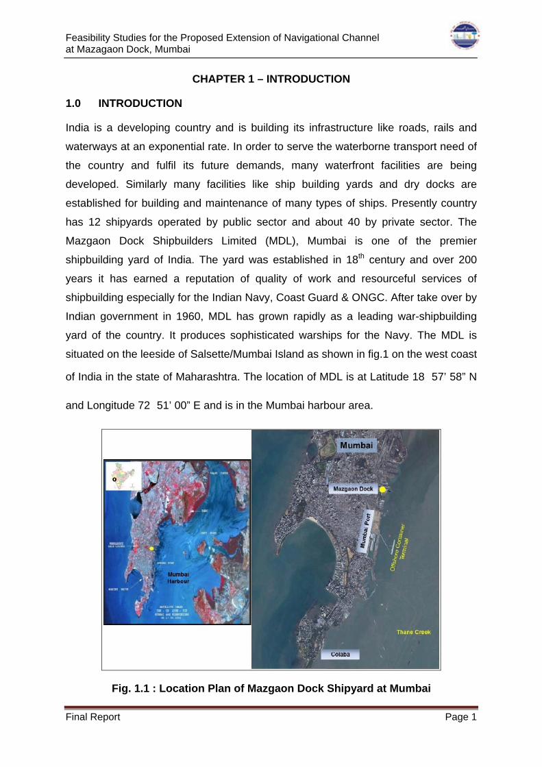
situated on the leeside of Salsette/Mumbai Island as shown in fig.1 on the west coast
of India in the state of Maharashtra. The location of MDL is at Latitude 18⁰ 57’ 58” N
and Longitude 72⁰ 51’ 00” E and is in the Mumbai harbour area.
Fig. 1.1 : Location Plan of Mazgaon Dock Shipyard at Mumbai
Feasibility Studies for the Proposed Extension of Navigational Channel at Mazagaon Dock, Mumbai
Final Report Page 2
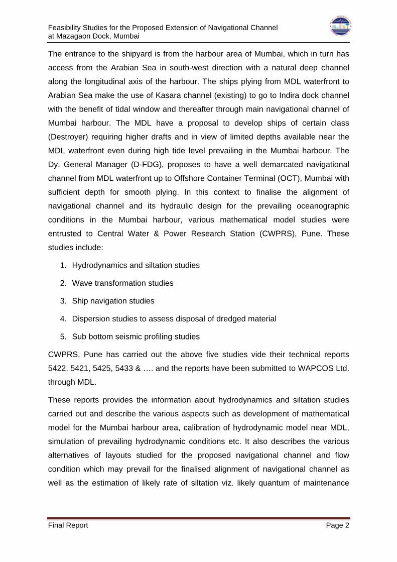
The entrance to the shipyard is from the harbour area of Mumbai, which in turn has
access from the Arabian Sea in south-west direction with a natural deep channel
along the longitudinal axis of the harbour. The ships plying from MDL waterfront to
Arabian Sea make the use of Kasara channel (existing) to go to Indira dock channel
with the benefit of tidal window and thereafter through main navigational channel of
Mumbai harbour. The MDL have a proposal to develop ships of certain class
(Destroyer) requiring higher drafts and in view of limited depths available near the
MDL waterfront even during high tide level prevailing in the Mumbai harbour. The
Dy. General Manager (D-FDG), proposes to have a well demarcated navigational
channel from MDL waterfront up to Offshore Container Terminal (OCT), Mumbai with
sufficient depth for smooth plying. In this context to finalise the alignment of
navigational channel and its hydraulic design for the prevailing oceanographic
conditions in the Mumbai harbour, various mathematical model studies were
entrusted to Central Water & Power Research Station (CWPRS), Pune. These
studies include:
1. Hydrodynamics and siltation studies
2. Wave transformation studies
3. Ship navigation studies
4. Dispersion studies to assess disposal of dredged material
5. Sub bottom seismic profiling studies
CWPRS, Pune has carried out the above five studies vide their technical reports
5422, 5421, 5425, 5433 & …. and the reports have been submitted to WAPCOS Ltd.
through MDL.
These reports provides the information about hydrodynamics and siltation studies
carried out and describe the various aspects such as development of mathematical
model for the Mumbai harbour area, calibration of hydrodynamic model near MDL,
simulation of prevailing hydrodynamic conditions etc. It also describes the various
alternatives of layouts studied for the proposed navigational channel and flow
condition which may prevail for the finalised alignment of navigational channel as
well as the estimation of likely rate of siltation viz. likely quantum of maintenance
Feasibility Studies for the Proposed Extension of Navigational Channel at Mazagaon Dock, Mumbai
Final Report Page 3
dredging to be carried out per annum. Also, these reports provide the information
about the wave transformation studies carried out and findings of the same.
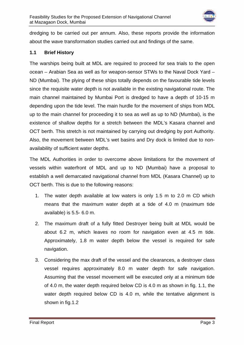
1.1 Brief History
The warships being built at MDL are required to proceed for sea trials to the open
ocean – Arabian Sea as well as for weapon-sensor STWs to the Naval Dock Yard –
ND (Mumbai). The plying of these ships totally depends on the favourable tide levels
since the requisite water depth is not available in the existing navigational route. The
main channel maintained by Mumbai Port is dredged to have a depth of 10-15 m
depending upon the tide level. The main hurdle for the movement of ships from MDL
up to the main channel for proceeding it to sea as well as up to ND (Mumbai), is the
existence of shallow depths for a stretch between the MDL’s Kasara channel and
OCT berth. This stretch is not maintained by carrying out dredging by port Authority.
Also, the movement between MDL’s wet basins and Dry dock is limited due to non-
availability of sufficient water depths.
The MDL Authorities in order to overcome above limitations for the movement of
vessels within waterfront of MDL and up to ND (Mumbai) have a proposal to
establish a well demarcated navigational channel from MDL (Kasara Channel) up to
OCT berth. This is due to the following reasons:
1. The water depth available at low waters is only 1.5 m to 2.0 m CD which
means that the maximum water depth at a tide of 4.0 m (maximum tide
available) is 5.5- 6.0 m.
2. The maximum draft of a fully fitted Destroyer being built at MDL would be
about 6.2 m, which leaves no room for navigation even at 4.5 m tide.
Approximately, 1.8 m water depth below the vessel is required for safe
navigation.
3. Considering the max draft of the vessel and the clearances, a destroyer class
vessel requires approximately 8.0 m water depth for safe navigation.
Assuming that the vessel movement will be executed only at a minimum tide
of 4.0 m, the water depth required below CD is 4.0 m as shown in fig. 1.1, the
water depth required below CD is 4.0 m, while the tentative alignment is
shown in fig.1.2
Feasibility Studies for the Proposed Extension of Navigational Channel at Mazagaon Dock, Mumbai
Final Report Page 4
Fig. 1.2 Depth Requirement Proposed by MDL
Fig. 1.3 Proposed Alignment of Navigational Channel from MDL to OCT
Feasibility Studies for the Proposed Extension of Navigational Channel at Mazagaon Dock, Mumbai
Final Report Page 5
1.2 Scope of Work
1.2.1 Objective of the Study
The objective of the study is to carry out the feasibility study for Deepening of
navigational channel from existing depth (-1.5 to -3.5m CD to -6m CD between the
northern end of the Mazagon waterfront to the Offshore Container Terminal (OCT) of
Mumbai Port Trust (MbPT). In order to achieve the objective above objective the
following scope of work were entrusted to WAPCOS limited.
1. Bathymetry survey
2. Collection of field data (tide, current, bed samples and water samples, SSC
etc.) for monsoon season as well as non-monsoon season.
3. Preparation of estimates of quantum of capital dredging for channel
deepening.
4. Cost estimate for capital dredging of the navigational channel.
5. Geotechnical survey of the area.
6. Preparation of project feasibility report based on the five mathematical model
studies conducted by CWPRS.
7. Preparation of Project feasibility report.
8. Environmental Impact assessment studies.
9. Obtaining Environmental clearance from MoEF for the creation of
Navigational channel.
1.3 Organisation of the Report
The entire project feasibility report is prepared on the following chapters.
a. Chapter 1 - Introduction
b. Chapter 2 - Site Conditions
c. Chapter 3 – Field Survey and Investigation
d. Chapter 4 – Mathematical Model Studies carried out at CWPRS
e. Chapter 5 – Budgetary Cost Estimate
f. Chapter 6. Concluding Remarks and Recommendations

Feasibility Studies for the Proposed Extension of Navigational Channel at Mazagaon Dock, Mumbai
Final Report Page 6
CHAPTER 2 – SITE CONDITION
2.1 Site Condition
MDL lies midway on the West coast of India, on the natural deep-water harbour of
Mumbai. The harbour spread over 400 km2 is protected by the mainland of Konkan
to its east and north and by the island city of Mumbai to its west. The harbour opens
to the south to the Arabian Sea. The prevailing site conditions at Mumbai harbour
are considered for studies under reference and are primarily classified as:
1. Bathymetry
2. Oceanographic Conditions
The bathymetry and oceanographic data was provided by MDL for the model studies
except the wind and wave data. The work of field investigation was entrusted by
MDL to M/s Water and Power Consultancy Services (WAPCOS) of India. The
environmental condition of wind, waves and current considered here is atmospheric
limiting condition which will allow the channel and its navigational area to be used
under normal operating condition.
2.2 Bathymetry
The bathymetry data of the project site is available in Indian Hydro graphic Survey
Chart no. 2016. A recent survey has been carried out by WAPCOS Limited for an
area of approximately 3.00 km X 1.50 km from the northern side of MDL turning
circle (Dharukhana) to the Offshore container terminal of MbPT and the area
covered is as shown in figure 2.1 Also previous pre and post sounding charts
(carried out by Maharashtra Maritime Board) has also been provided by MDL. From
the bathymetry it is found that the depth at areas immediately in front of MDL is of
the order of -1.8 to -2.2m below CD whereas it is going upto an extent of -3.8 m
below CD towards OCT berth. MDL is now maintaining a depth of -2 m below CD in
Kasara channel.
Feasibility Studies for the Proposed Extension of Navigational Channel at Mazagaon Dock, Mumbai
Final Report Page 7
Fig. 2.1 Bathymetry survey carried out for studies (Year 2015)
2.3 Wind
2.3.1 Offshore Wind Data
Wind data all along the Indian coast is measured and compiled by Indian
Meteorological Department (IMD). This data reported for the 16 years from 1986 to
2001 indicate that for 95% of the days in a year the wind speed is less than 20 m/sec
off the coast of Mumbai. It is also seen that maximum wind speed is about 30 m/sec
in the area covered between Latitude 15⁰ N to 20⁰ N and Longitude 70⁰ E to 75⁰ E,
however, its percentage of occurrence in a year is only 1.0.
2.3.2 Inshore Wind Data
The wind data is being measured and collected in Mumbai harbour for past 20 years.
The wind data analysis carried out reveals that during south-west monsoon (June to
September), predominant wind direction is from South to West North West and
average wind speed recorded during monsoon period is in the range 8 m/sec to 10
m/sec. in non-monsoon period (March and April) the percentage of occurrence of low
wind speed i.e. in the range 0.8 m/s to 3 m/s is significant, while in south-west
Feasibility Studies for the Proposed Extension of Navigational Channel at Mazagaon Dock, Mumbai
Final Report Page 8
monsoon (May, June and July) percentage of occurrence of higher wind speed
between 5.0 m/s to 10.5 m/s is more.
2.4 Tides
The typical tidal levels prevailing at Mumbai harbour based on past data at Apollo
Bundar near Gate Way of India is given below. The tides at Mumbai are semi-
diurnal.
Table 2.1 : Tidal Levels
Water Level Magnitude
Highest High Water +5.38 m
Mean High Water Spring +4.42 m
Mean High Water Neap +3.30 m
Mean Sea Level +2.5 m
Mean Low Water Neap +1.85 m Mean Low Water Spring +0.76 m
Lowest Low Water -0.44 m
Also tidal data was collected by WAPCOS Limited for a period of one month during
monsoon ( Aug-Sep 2015) and non-monsoon (Jan 2015) season for a period of one
month each at four locations in Mumbai harbour area viz. i) Apollo Munder (MbPT),
ii) Vashi Bridge (Thane Creek), iii) Ulwe Bunder (Panvel creek), iv) Rewas creek
(Dharamtar creek) and the details of are included in Chapter 3.
2.5 Current
The currents in the harbour are essentially caused by the tides and are not
influenced to any extent by monsoons etc. The tidal flow is unsteady and the
magnitude and direction of the current varies with respect to location, time and
depth. However, the current strength in and around MDL area (C1 = 180 57’46.82”
N, 720 51’20.09”E, C2 = 180 57’14.27” N, 720 51’22.68”E, C3 = 180 58’24.40” N, 720
52’46.31”E) was measured by WAPCOS limited for a period of 15 days during
monsoon and non-monsoon season. The results of the current strength and direction
are included in chapter 3.

Feasibility Studies for the Proposed Extension of Navigational Channel at Mazagaon Dock, Mumbai
Final Report Page 9
2.6 Wave
The predominant waves are the swell waves generated by deep sea storms. These
mainly arise just before and during the South West monsoon. The statistical analysis
indicates that most wave periods fall between 6 seconds and 10 seconds.
During the continuance of the North-East monsoon, North-Easterly winds known as
"Elephantas" blow for short durations during the months of October-November. As
the fetch and duration of these winds are limited, the "Significant height" of the
resulting waves is not likely to exceed 1 metre with period ranging from 3 to 5
seconds.
2.7 Relative Humidity
Relative humidity ranges from 61% to 87% being the highest in the monsoon period.
During the winter months (Nov-Jan) relative humidity ranges from 61% to 72%.
Mean daily temperature ranges from 24 Degrees C to 33 Degrees C except during
the winter period when the minimum temperature may fall to about 19 Degrees. The
hotter months are March, April, May and June.
2.8 Temperature and Salinity
The analysis of data collected on temperature of sea water during non-monsoon
season for spring tide indicate that the temperature varies between 23°C and 25°C,
while during neap, it varies between 23°C and 25°C. Similarly during monsoon
season it varies between 28°C and 30°C for spring tide, while for neap tide it is 27°C
and 29°C.
The salinity measured during non-monsoon spring tide varies between 29.9 ppt and
35.2 ppt, while during neap tide it is between 29.9 ppt and 34.3 ppt. similarly, during
monsoon, it varies between 26 ppt and 31.2 ppt for spring tide & 21.8 ppt and 27.8
ppt for neap tide. These salinity values mentioned above are deduced from values
measured mid-depth. Also, minimum salinity is observed during monsoon season,
while maximum is during non-monsoon.
The data on temperature and salinity was considered for calculating the density of
sea water and it has been found to vary between 1012 kg/cum and 1024 kg/cum.

Feasibility Studies for the Proposed Extension of Navigational Channel at Mazagaon Dock, Mumbai
Final Report Page 10
2.9 Rainfall
The climate of the region has a regular seasonal variation determined by the
occurrence of two annual monsoons. The South-West monsoon period extends from
June to September. Most of the annual rainfall occurs during the South-West
monsoon, the average monthly rainfall being about 45 cm. Rain during the North-
East monsoon is slight. The average annual rainfall over 20 years is 193 cm.
2.10 Bed and water samples
Bed samples were collected by WAPCOS Limited at current meter deployed
locations (C1, C2 and C3) on Jan 2015 and hourly water samples were collected
during monsoon and non-monsoon season (Jan 2015 and Sep 2015) for 24 hours
and the results are explained in chapter 3.

Feasibility Studies for the Proposed Extension of Navigational Channel at Mazagaon Dock, Mumbai
Final Report Page 11
CHAPTER 3 – FIELD SURVEY AND INVESTIGATION
3.1 General
MDL lies midway on the West coast of India, on the natural deep-water harbour of
Mumbai. The harbour spread over 400 km2 is protected by the mainland of Konkan
to its east and north and by the island city of Mumbai to its west. The harbour opens
to the south to the Arabian Sea.
The work of field investigation was entrusted by MDL to M/s Water and Power
Consultancy Services (WAPCOS) of India. For this WAPCOS Ltd has collected data
for monsoon and non-monsoon season during August 2015 and January 2016
respectively. The field data collected are as follows:
1. Bathymetry
2. Tides
3. Currents
4. Bed Samples
5. Water Samples
6. Geotechnical Investigation
3.2 Bathymetry
Bathymetry survey pertaining to an area of approximately 3.00 km X 1.50 km was
carried out by WAPCOS Limited from the northern side of MDL turning circle
(Dharukhana) to the Offshore container terminal of MbPT and the area covered is as
shown in figure 2.1 From the bathymetry it is found that the depth at areas
immediately in front of MDL is of the order of 1.8 to 2.2m below CD whereas it is
going upto an extent of 3.8 to 4m below CD towards OCT berth. MDL is now
maintaining a depth of 2 m below CD in Kasara channel. The final report on
bathymetry survey carried out was submitted to MDL on June 2015 and the same is
attached as Annexure I in this report.

Feasibility Studies for the Proposed Extension of Navigational Channel at Mazagaon Dock, Mumbai
Final Report Page 12
Fig. 3.1 Bathymetry Survey carried out for Studies (Year 2015)
3.3 Field Data Collection for Monsoon Season
3.3.1 Tides
Automatic Tide Gauges (ATGs) were installed at four locations on 28 August 2015
for a period of one month to log tide data in every 10 minutes. The locations are as
follows and given in fig 3.2:
1. Apollo Bandar (MbPT)
2. Vashi Bridge (Thane Creek)
3. Ulwe Bandar/Ambuja (Panvel Creek)
4. Rewas Jetty (Dharamtar Creek)
The collected data indicates that the tides at the locations were observed to be
semidiurnal, with diurnal inequality. The observed heights of tide at MbPT were
reduced with respect to MSL-CD relationship at Apollo Bandar (MSL-CD is 2.51 m).

Feasibility Studies for the Proposed Extension of Navigational Channel at Mazagaon Dock, Mumbai
Final Report Page 13
This MSLCD relation was applied to all three locations. The Maximum range of tide
observed was 5.44 m during the full moon phase and minimum range was observed
to be 0.69 m during neaps.
Fig. 3.2 Locations of tide and current measurements in Mumbai Harbour
Table 3.1: Tidal ranges at MbPT, Ambuja, Vashi and Rewas Locations
Location Maximum Range (m)
Date of Max Range Observed
Minimum Range (m)
Date of Min Range Observed
MbPT 4.75 31-08-2015 0.69 22-09-2015
Vashi Bridge 5.44 31-08-2015 0.79 22-09-2015
Ulwe (Ambuja) 5.31 28-09-2015 0.77 22-09-2015
Rewas 4.94 31-08-2015 0.72 22-09-2015

Feasibility Studies for the Proposed Extension of Navigational Channel at Mazagaon Dock, Mumbai
Final Report Page 14
Figure 3.3: Tide graph at MbPT, Ambuja, Vashi and Rewas during springs
3.3.2 Current
At the proposed locations C1 (180 57’ 46.82” N 720 51’ 20.09” E), C2 (180 57’ 14.27”
N 720 51’ 22.68” E) and C3 (180 57’ 24.40” N 720 52’ 46.31” E), S4 current meter and
Acosticdopler current profilers (ADCP) were installed respectively on 12 September
2015 for a period of 15 days.
Currents at the location were observed to be tidal in nature, with predominantly
North-North-East flow during the Flood and South-South-West flow during the Ebbs
at location C1 and C2. At location C3 Ebb flow is directed to South-West and Flood
flow to North-East.Maximum current speeds were observed during the spring tides
as expected. The speed of the Ebb currents was observed to be stronger than the
Flood currents. Maximum current speeds observed at mid depth during Ebb were
1.046 m/s @ 232.80 T at location C3, 0.739 m/s @199.70 T at location C1 and 0.728
m/s @ 191.10 T at location C2. Maximum current speeds observed at mid depth
during Flood were 0.814 m/s @ 36.60 T at location C3, 0.613 m/s @ 022.60 T at
location C2 and 0.510 m/s @ 012.30 T at location C1.
3.3.3 Water Sample
Water samples from mid-depth at three locations (C1, C2 &C3) were collected hourly
for 24 hours during neap tide (21 - 22 September 2015) and spring tide (28 – 29
September 2015) and the temperatures were manually recorded. Also, 01 number
Feasibility Studies for the Proposed Extension of Navigational Channel at Mazagaon Dock, Mumbai
Final Report Page 15
water sample of 200 litre at each location was collected from the mid depth (during
Neap & Spring) for Grain size distribution of SSC.
The detailed report of monsoon season survey submitted to MDL is attached as
Annexure II of this report.
3.4 Field Data Collection for Non-Monsoon Season
3.4.1 Tides
Automatic Tide Gauges (ATGs) were installed at following location on 4th January
2015 for a period of one month to log tide data in every 10 min interval for 15 days.
1. Ballard Pier Extension (BPX – MbPT)
2. Vashi Bridge (Thane Creek)
3. Ambuja Jetty (Panvel Creek)
4. Rewas Jetty (Dharamtar Creek)
Tides at the locations were observed to be semidiurnal with diurnal inequality. The
observed heights of tide at BPX –MbPT were reduced to the CD level at MbPT. This
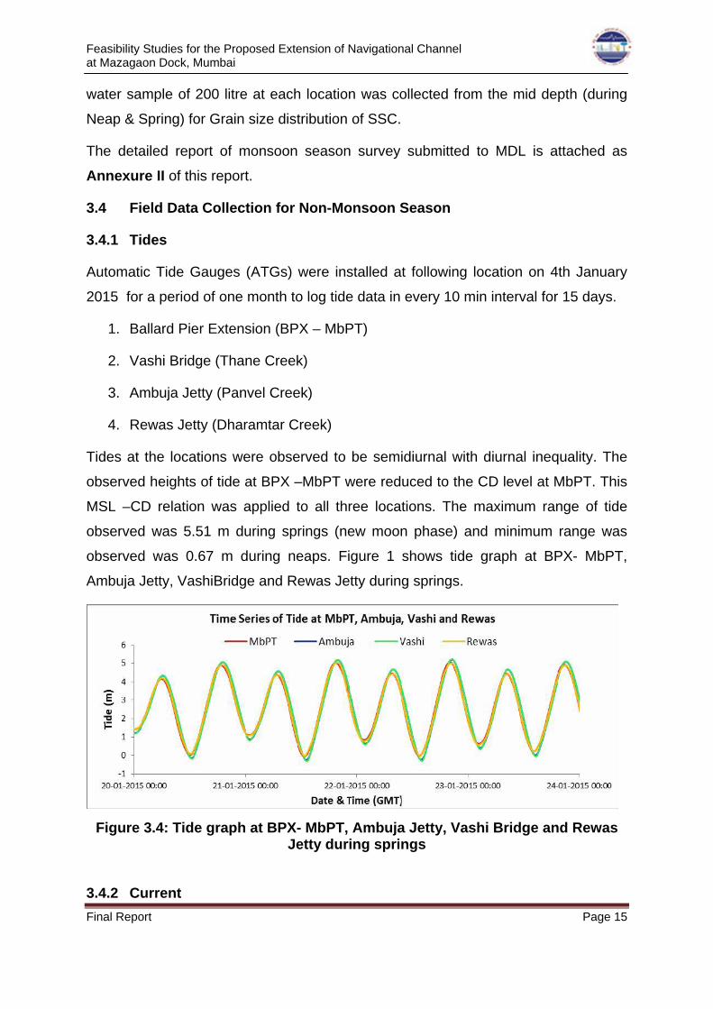
MSL –CD relation was applied to all three locations. The maximum range of tide
observed was 5.51 m during springs (new moon phase) and minimum range was
observed was 0.67 m during neaps. Figure 1 shows tide graph at BPX- MbPT,
Ambuja Jetty, VashiBridge and Rewas Jetty during springs.
Figure 3.4: Tide graph at BPX- MbPT, Ambuja Jetty, Vashi Bridge and Rewas Jetty during springs
3.4.2 Current
Feasibility Studies for the Proposed Extension of Navigational Channel at Mazagaon Dock, Mumbai
Final Report Page 16
At proposed locations C1, C2 and C3, initially S4 current meters and ADCP were
installed respectively on 19th January 2015. ADCP at C3 was swapped with S4
current meter at C2 location on 22.01.2015 as per observation during joint site visit
of WAPCOS, CWPRS & MDL on 22nd January 2015.
Currents at the locations were observed to be tidal in nature, with predominantly
North –North – East (NNE) flow during the floods and South – South – West (SSW)
flow during the ebbs at current location C1 and C2. At location C3, the floods flowing
to North – East (NE) and the ebbs flowing to South – West (SW). Maximum current
speeds were observed during the spring tides as expected. The speed of Ebb
currents was observed to be stronger than Flood currents. Maximum current speeds
observed at mid depth during Ebb were 1.028 m/s @ 229.10° T at location C3, 0.967
m/s @192.80°T at location C2 and 0.836 m/s @ 198.50°T at location C1
respectively. Maximum current speeds observed at mid depth during Flood were
0.893 m/s @ 41.20°T at location C3, 0.744 m/s @15.0°T at location C2 and 0.630
m/s @ 20.30°T at location C1 respectively.
3.4.3 Water Sample
Water samples collected from specified locations during spring and neap tides and
analysed for standard parameters viz. Temperature in Celsius (°C), pH, Salinity in
ppt and Total Suspended Solids in Milligram per Litre (mg/l). The temperature in sea
water at locations (C1, C2 and C3) varies from 23°C to 25.5 °C. Whereas the pH in
sea water at locations (C1, C2 and C3) varies from 8.30 to 8.60, and the salinity in
sea water at locations (C1, C2 and C3) varies from 29.9 ppt to 35.2 ppt. The total
suspended solid in sea water at locations (C1, C2 and C3) varies from 478 mg/l to
1152 mg/l and it is observed that generally during spring tides concentration of
suspended solids were maximum compare to neap tides.
3.4.4 Bed Sample
Bed samples collected from specified locations and analysed for grain / particle size
distribution (D50), from analysis it is observed that particle of clay and silt were more,
except at bed sample location – BS 5. Diameter of the particle at 50 percent (D50)
varies from 0.0004 to 0.0012.

Feasibility Studies for the Proposed Extension of Navigational Channel at Mazagaon Dock, Mumbai
Final Report Page 17
The detailed report of non-monsoon season survey submitted under the name ……
to MDL on June 2016 is attached as Annexure III of this report.
3.5 Comparison of Monsoon with Non-Monsoon Observations
3.5.1 Tide
The Tides at the four locations were categorized as mainly semi diurnal tides with
diurnal inequality. Tidal ranges observed during monsoon period is slight lesser than
the tidal range observed during non-monsoon period.
Table 3.2: Comparison of Tidal ranges during non-monsoon and monsoon Period
Maximum Range (m) Date of Max Range Observed Location
Non-Monsoon Monsoon Non-Monsoon Monsoon
MbPT 5.06 4.75 22-01-2015 31-08-2015
Vashi Bridge 5.51 5.44 22-01-2015 31-08-2015
Ulwe (Ambuja) 5.43 5.31 22-01-2015 28-09-2015
Rewas 5.05 4.94 22-01-2015 31-08-2015
3.5.2 Currents
Current observed at the three locations is mainly tidal. A maximum current speed
observed during monsoon period is slightly lesser than the observation during non-
monsoon period.
Location C1
Table 3.3: Comparison of Ebb current during non-monsoon & monsoon period
at location C1
Max Current Speed (m/s)
Direction of Current Max (⁰True)
Date & Time of Max Current (IST)
Level Non-
Monsoon Monsoon
Non- Monsoon
MonsoonNon-
Monsoon Monsoon
Mid Depth
0.836 0.739 198.5 199.7 21/01/2015
02:40 13/09/2015
14:50

Feasibility Studies for the Proposed Extension of Navigational Channel at Mazagaon Dock, Mumbai
Final Report Page 18
Table 3.4: Comparison of Flood current during non-monsoon and monsoon period at location C1
Max Current Speed (m/s)
Direction of Current Max (⁰True)
Date & Time of Max Current (IST)
Level Non-
Monsoon Monsoon
Non- Monsoon
MonsoonNon-
Monsoon Monsoon
Mid Depth
0.630 0.510 20.30 12.3 20/01/2015
22:30 14/09/2015
19:40
Location C2 Table 3.5: Comparison of Ebb current during non-monsoon & monsoon period
at location C2 Max Current Speed
(m/s) Direction of Current
Max (⁰True) Date & Time of Max
Current (IST) Level
Non- Monsoon
MonsoonNon-
MonsoonMonsoon
Non- Monsoon
Monsoon
Mid Depth
0.967 0.728 192.8 191.1 22/01/2015
04:00 29/09/2015
03:00 Near
Bottom 0.770 0.624 189.6 189.5
23/01/2015 04:30
29/09/201503:00
Table 3.6: Comparison of Flood current during non-monsoon & monsoon period at location C2
Max Current Speed
(m/s) Direction of Current
Max (⁰True) Date & Time of Max
Current (IST) Level
Non- Monsoon
MonsoonNon-
MonsoonMonsoon
Non- Monsoon
Monsoon
Mid Depth
0.744 0.613 15.0 22.6 22/01/2015
11:00 29/09/2015
09:40 Near
Bottom 0.502 0.601 13.4 22.1
22/01/2015 23:10
29/09/201509:40
Location C3

Feasibility Studies for the Proposed Extension of Navigational Channel at Mazagaon Dock, Mumbai
Final Report Page 19
Table 3.7: Comparison of Ebb current during non-monsoon & monsoon period
at location C3
Max Current Speed (m/s)
Direction of Current Max (⁰True)
Date & Time of Max Current (IST)
Level Non-
Monsoon Monsoon
Non- Monsoon
MonsoonNon-
Monsoon Monsoon
Mid Depth
1.028 1.046 229.1 232.8 24/01/2015
05:40 28/09/2015
15:00
Table 3.8: Comparison of Flood current during non-monsoon and monsoon period at location C3
Max Current Speed
(m/s) Direction of Current
Max (⁰True) Date & Time of Max
Current (IST) Level
Non- Monsoon
MonsoonNon-
MonsoonMonsoon
Non- Monsoon
Monsoon
Mid Depth
0.893 0.814 41.2 36.6 25/01/2015
13:20 28/09/2015
09:30
3.6 Geotechnical Investigation
Geotechnical investigations were carried out to find the nature of soil beneath
seabed. The geotechnical field investigation was commenced on July 13, 2016 and
completed on July 25, 2016 under the constant supervision of MDL representatives.
The soil Investigation was carried out as per IS 1892 – 1979: The rig deployed at the
site was rotary type drilling rig-mechanical feed with mud circulation method. These
rigs have an arrangement for driving and extracting of casing, boring, and drilling by
mud circulation method, conducting SPT tests, collection of disturbed & undisturbed
samples. Casing was used to support sides of borehole until stiff strata was
encountered.

Feasibility Studies for the Proposed Extension of Navigational Channel at Mazagaon Dock, Mumbai
Final Report Page 20
Fig 3.5: Locations of Marine Boreholes (BH-1 to BH-08)
A. Standard Penetration Test (SPT)
Standard Penetration Tests (i.e. SPT) were carried out at intervals of 1.0 meters
and at any change of strata, in accordance with IS 2131 – 1981. Using this
procedure, the split spoon sampler resting on the bottom of borehole was allowed to
sink under its own weight. The entire sampler may sometimes sink under its own
weight when very soft sub-soil stratum was encountered. Under such conditions, it
may not be necessary to give any blow to the split spoon sampler and SPT value is
indicated as zero.
This split-spoon sampler was driven into the soil by 63.5 kilograms weight falling
through 75 centimeters height. After an initial set of 15 centimeters, the number of
blows required to drive the sampler an additional 30 centimeters, is known as
“penetration resistance” or “N value”. The N values are indicative of the relative
density of cohesion less soils and consistencies of cohesive soils. Each sample
retrieved from SPT spoon was inspected for visual identification of strata as per IS
1498. The samples were preserved in polythene bags, duly numbered and N values
mentioned for proper identification.

Feasibility Studies for the Proposed Extension of Navigational Channel at Mazagaon Dock, Mumbai
Final Report Page 21
The sampler was lowered to the bottom of the borehole. The following information is
noted and recorded:
a. Depth of bottom of borehole below ground level,
b. Penetration of the sampler into the soil under the combined weight of
sampler and rods (noted from readings of the scale over the drill rod
at the top),
c. Depth of bottom of casing below ground level.
B. Rock Drilling
When SPT refusal was obtained in hard strata, the diameter of the borehole is
reduced to NX (i.e. 75 mm ɸ bore). Tungsten carbide, Diamond impregnated bit was
used in weathered/ hard rock strata. Rock coring was done using diamond bit and
double tube core barrel to obtain good quality rock samples. Percent Rock Core
Recovery (% RCR) and percent Rock Quality Designation (%RQD) where, % RQD =
100 x Sum of Length of Rock Pieces (cm) [each having lengths > 10 cm]/ Total
Length of Core Run (cm). Rock core samples recovered in drilling are arranged
sequentially and numbered. All samples were stored in sturdy good quality steel
boxes and boxes are identified.
C. Borehole Termination Criterion
Bore holes are terminated at depths as per specifications or as directed by the
contract.
D. Water Sampling
Collection of ground water sample for chemical analysis is as per IS 3025 or as per
the specification.
3.7 Laboratory Test
The laboratory testing was aimed at obtaining the following characteristics of
different layers.
i. Grain size distribution/Sieve analysis
ii. Atterberg’s Limit tests
Feasibility Studies for the Proposed Extension of Navigational Channel at Mazagaon Dock, Mumbai
Final Report Page 22
iii. Chemical analysis of water samples
3.8 Test on Soil Samples
Following Laboratory tests were carried out on disturbed soil samples obtained from
boreholes.
Sieve Analysis as per IS-2720(Part-4)
Atterberg’s limits as per IS2720(Part-5)
IS Classification IS1498
Chemical analysis of Soil samples to determine Sulphate Content,
Chloride Content, PH , Nitrate Content, Sodium Content, Potassium
Content, Calcium Content
3.9 Test on Rock Samples
Following tests were conducted on rock samples
Unit Weight as per IS:13030
Specific gravity as perIS:13030
Porosity as perIS:13030
3.10 Test on Water Samples
Following tests were conducted on water samples
Chemical analysis of water samples to determine pH, Chloride contents, Total
Dissolved solids, Nitrate Content and Calcium Content.
3.11 Exploration Program
Sinking of boreholes was performed in accordance with IS: 1892 – 1979.
Multipurpose rotary drilling rig mechanically operated is used for sinking the
boreholes. The rig deployed was generally suitable for all Geotechnical
Investigation work and had an arrangement for driving and extraction of casing,
boring and Diamond Core drilling by mud circulation method.
a. Total Eight borings, designated BH-1 to BH-8, are performed to a
different depths below sea bed level.
Feasibility Studies for the Proposed Extension of Navigational Channel at Mazagaon Dock, Mumbai
Final Report Page 23
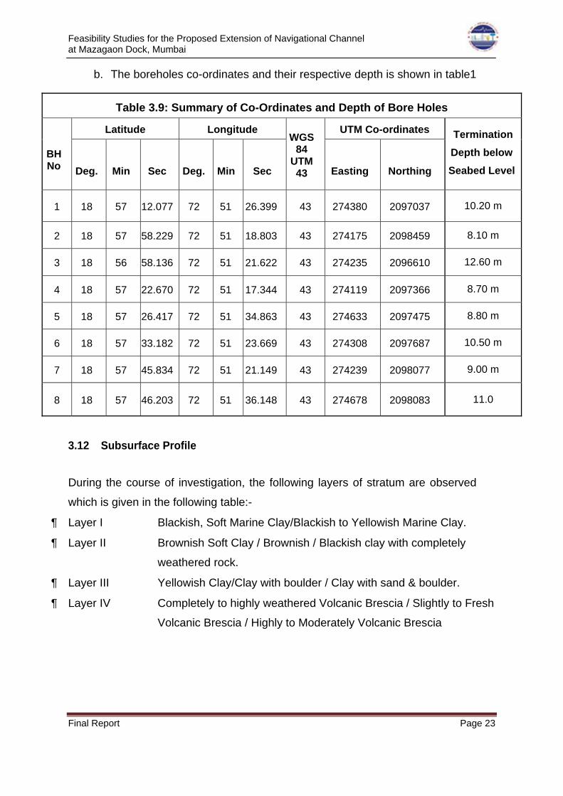
b. The boreholes co-ordinates and their respective depth is shown in table1
Table 3.9: Summary of Co-Ordinates and Depth of Bore Holes
Latitude Longitude UTM Co-ordinates
BH No
Deg.
Min
Sec
Deg.
Min
Sec
WGS84
UTM 43
Easting
Northing
Termination
Depth below
Seabed Level
1 18 57 12.077 72 51 26.399 43 274380 2097037 10.20 m
2 18 57 58.229 72 51 18.803 43 274175 2098459 8.10 m
3 18 56 58.136 72 51 21.622 43 274235 2096610 12.60 m
4 18 57 22.670 72 51 17.344 43 274119 2097366 8.70 m
5 18 57 26.417 72 51 34.863 43 274633 2097475 8.80 m
6 18 57 33.182 72 51 23.669 43 274308 2097687 10.50 m
7 18 57 45.834 72 51 21.149 43 274239 2098077 9.00 m
8 18 57 46.203 72 51 36.148 43 274678 2098083 11.0
3.12 Subsurface Profile
During the course of investigation, the following layers of stratum are observed
which is given in the following table:-
Layer I Blackish, Soft Marine Clay/Blackish to Yellowish Marine Clay.
Layer II Brownish Soft Clay / Brownish / Blackish clay with completely
weathered rock.
Layer III Yellowish Clay/Clay with boulder / Clay with sand & boulder.
Layer IV Completely to highly weathered Volcanic Brescia / Slightly to Fresh
Volcanic Brescia / Highly to Moderately Volcanic Brescia
Feasibility Studies for the Proposed Extension of Navigational Channel at Mazagaon Dock, Mumbai
Final Report Page 24
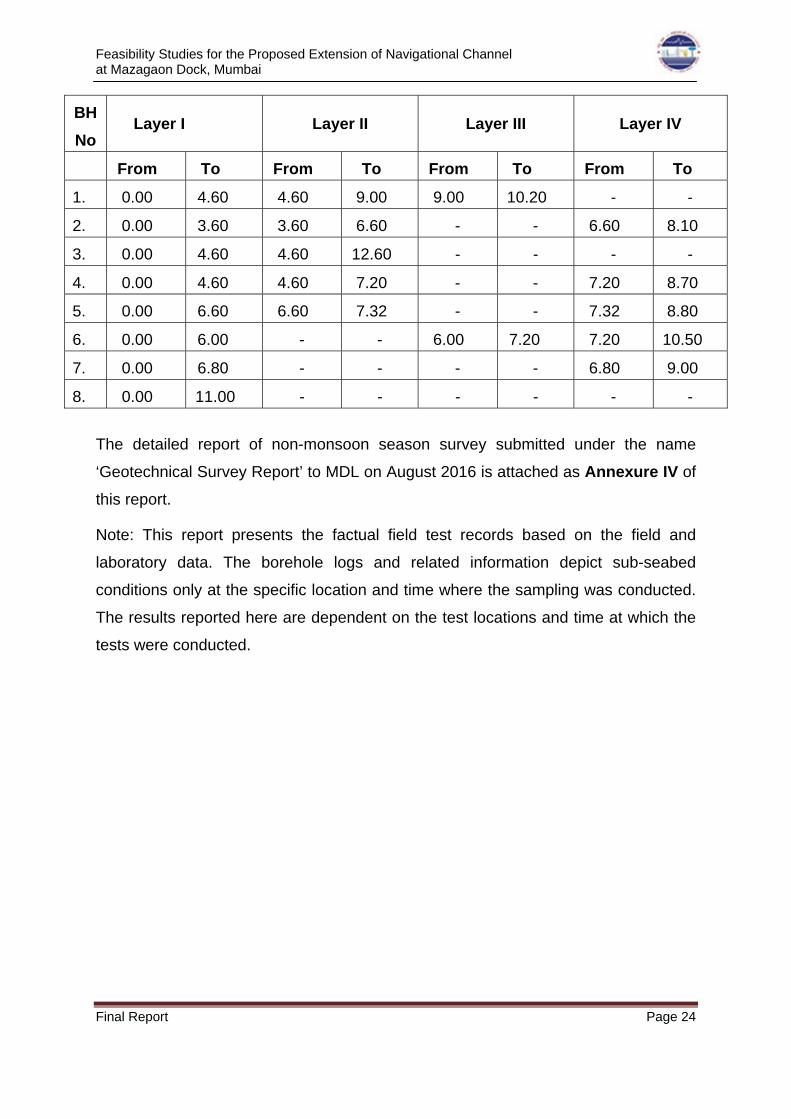
BH
No Layer I Layer II Layer III Layer IV
From To From To From To From To
1. 0.00 4.60 4.60 9.00 9.00 10.20 - -
2. 0.00 3.60 3.60 6.60 - - 6.60 8.10
3. 0.00 4.60 4.60 12.60 - - - -
4. 0.00 4.60 4.60 7.20 - - 7.20 8.70
5. 0.00 6.60 6.60 7.32 - - 7.32 8.80
6. 0.00 6.00 - - 6.00 7.20 7.20 10.50
7. 0.00 6.80 - - - - 6.80 9.00
8. 0.00 11.00 - - - - - -
The detailed report of non-monsoon season survey submitted under the name
‘Geotechnical Survey Report’ to MDL on August 2016 is attached as Annexure IV of
this report.
Note: This report presents the factual field test records based on the field and
laboratory data. The borehole logs and related information depict sub-seabed
conditions only at the specific location and time where the sampling was conducted.
The results reported here are dependent on the test locations and time at which the
tests were conducted.

Feasibility Studies for the Proposed Extension of Navigational Channel at Mazagaon Dock, Mumbai
Final Report Page 25
CHAPTER 4 – MATHEMATICAL MODEL STUDIES CARRIED OUT AT CWPRS,
PUNE
4.1 General
Mazagon Dock Limited is situated in Mumbai Harbour area on the leeside of Salsette
/ Mumbai Island. The existing channel from Mazagon Dock to the end of Kasara
channel is proposed to be extended up to Offshore Container terminal (OCT) of
Mumbai Port Trust. In this regard, the following mathematical model studies were
referred to CWPRS, Pune to assess the viability of the deepening and extension of
channel from MDL water front up to OCT berth, MbPT.
1. Mathematical model studies for hydrodynamics and siltation for the proposed
extension of navigational channel.
2. Wave transformation studies to determine wave conditions.
3. Desk studies for the extension of proposed channel
4. Dispersion study to assess feasibility of flood dumping ground for disposal of
dredged material.
5. Sub–bottom seismic profiling of proposed navigational channel area.
Accordingly, CWPRS has carried out the mention studies vide technical reports
numbers viz., 5422, 5421, 5425,
4.2 Mathematical Model Studies for Hydrodynamics and Siltation
The technical report vide no. 5422 describes the mathematical model studies carried
out to study the prevailing tidal flow conditions and assess the likely rate of siltation
along the proposed channel from MDL waterfront up to OCT of Mumbai port. This
provides input to the ship navigation studies to finalise the alignment and hydraulic
design of the channel. The oceanographic data collected during monsoon and non-
monsoon season (2015) in Mumbai harbour by WAPCOS limited was used for the
studies.
The studies reveal that the existing rate of siltation is about 1.2 m/annum,
wherein depth of 2m below CD is being maintained. The two alternative

Feasibility Studies for the Proposed Extension of Navigational Channel at Mazagaon Dock, Mumbai
Final Report Page 26
alignments of navigational channel proposed by MDL were initially studied and
based on preliminary studies, it reveal that flow field is not suitable with the
alignments proposed, which may create problem for ship manoeuvring and
increase in siltation. Hence a third alignment based on study of prevailing flow
field as Option-III was considered by CWPRS for further studies in consultation
with project officials. The flow field observed being parallel along the navigational
channel extension (Option-III), irrespective of phase of tide; it was considered for
deciding the cross section of channel based on ship navigation studies. The
input data was provided from hydrodynamic (tide and wave) studies. The channel
from MDL up to end of Kasara channel and end of Kasara channel to OCT was
considered to be deepened to 5.5 m and 6.0 m below CD of Apollo Bundar
respectively. The studies carried out with finalised alignment and cross section of
channel reveal that flow conditions are further improved. The likely rate of
maintenance dredging in the above channel will be about 1.1 Million cum per
annum. The quantum of capital dredging will be about 2.5 Million cum and based on
borehole data provided by MDL, material to be dredged is silty clay/clay. As such
finalised alignment of navigational channel (Option-III) has improved flow
conditions with minimal rate of siltation and the same can be adopted for the
proposed extension of navigational channel from MDL to OCT berth, Mumbai.
The complete technical report submitted by CWPRS on hydrodynamic and siltation
studies is attached in this report as ANNEXURE IV for ready reference
4.2.1 Recommendations by CWPRS
The recommendation made by CWPRS through their Technical report No. 5422 is
as follows.
“The alignment of channel and cross sections finalised based on the tidal
hydrodynamics and siltation studies can be adopted for implementation at site for
the movement of destroyer class of ship under consideration. The depths in the
proposed navigational channel needs to be maintained to the desired depths viz.
5.5 m from MDL waterfront up to end of Kasara channel and 6.0 m from end of
Kasara channel up to OCT berth of Mumbai respectively [below CD of Apollo
Bundar, Mumbai] by carrying out regular maintenance dredging. The water depths
in the final layout of the navigational channel (10.0 m and 10.5 m in portion AB and
Feasibility Studies for the Proposed Extension of Navigational Channel at Mazagaon Dock, Mumbai
Final Report Page 27
BC respectively) should be assured by project Authority before plying of destroyer
class of ship from MDL waterfront up to OCT berth of Mumbai port.”
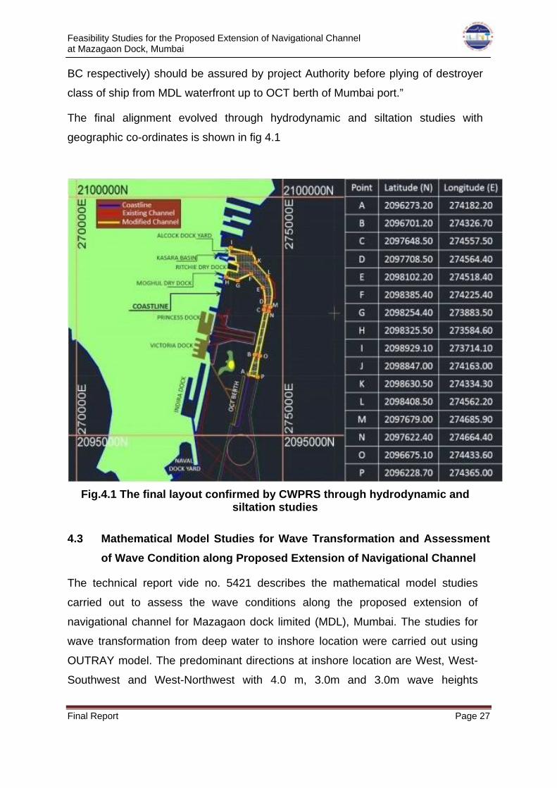
The final alignment evolved through hydrodynamic and siltation studies with
geographic co-ordinates is shown in fig 4.1
Fig.4.1 The final layout confirmed by CWPRS through hydrodynamic and siltation studies
4.3 Mathematical Model Studies for Wave Transformation and Assessment
of Wave Condition along Proposed Extension of Navigational Channel
The technical report vide no. 5421 describes the mathematical model studies
carried out to assess the wave conditions along the proposed extension of
navigational channel for Mazagaon dock limited (MDL), Mumbai. The studies for
wave transformation from deep water to inshore location were carried out using
OUTRAY model. The predominant directions at inshore location are West, West-
Southwest and West-Northwest with 4.0 m, 3.0m and 3.0m wave heights

Feasibility Studies for the Proposed Extension of Navigational Channel at Mazagaon Dock, Mumbai
Final Report Page 28
respectively, 10 sec. period. The Wave transformation studies further inside
Mumbai harbour were carried out using MIKE-21(FM) module and wave model
was calibrated for prevailing Wind and Wave conditions in Mumbai harbour based
on the data available at CWPRS. The calibration of wave model was carried out
using wind as a variable parameter from W-SW direction being predominant
direction. The bathymetry of recently deepened entire main navigational channel
of Mumbai (2014) alongwith for Mazagaon dock area (2015) was used for carrying
out studies under consideration. The final alignment of navigational channel
evolved by tidal hydrodynamic studies was used to determine wave conditions (Hs
& p) all along the navigational channel (MDL – OCT) for the existing bathymetry
condition. This wave data was used as one of input parameter for ship navigation
studies to determine the cross sectional dimensions of navigational channel along
its length for the draft requirement of the naval ship under consideration. Based on
ship navigation studies, depth of 5.5 m and 6.0 m below Chart datum (CD) of
Mumbai for MDL – Kasara channel and further up to OCT respectively and wave
conditions all along finalised alignment/dimensions of navigational channel of MDL
for prevailing wave conditions were again determined to confirm the suitability of
alignment and dimensions of extension of navigational channel finalised for
Mazagaon dock. The studies reveal that max. value of Hs= 0.61m and Hs = 0.75
m for portion of channel between MDL – End of Kasara channel (AB) and End of
Kasara channel to OCT (BC) respectively may occur. The wave conditions
determined for finalised alignment/layout of navigational channel confirms that
channel dimensions are safe and can be implemented.
The complete technical report submitted by CWPRS on Wave transformation and
assessment of wave condition studies is attached in this report as ANNEXURE V for
ready reference
4.3.1 Recommendations by CWPRS
The recommendation made by CWPRS through their Technical report No. 5421 is
as follows.
“The final alignment and cross sections for the proposed extension of navigational
channel from MDL up to OCT berth of Mumbai Port under consideration evolved
through model studies is suitable for plying the destroyer class of ships proposed

Feasibility Studies for the Proposed Extension of Navigational Channel at Mazagaon Dock, Mumbai
Final Report Page 29
by MDL for the normal operable wave conditions prevailing in the Mumbai
Harbour.”
4.4 Desk Studies for Design of Proposed Extension of Navigational Channel
The technical report vide no. 5425 describes the desk studies carried out for design
of extension of navigational channel. Extension of the navigational channel from
MDL to Offshore Container Terminal channel for safe manoeuvring of Destroyer
with 1 to 2 knots speed, under normal environmental conditions, was designed
using PIANC Guidelines. These studies include determination of alignment of
extension of channel and channel dimensions in terms of its width and depth.
Studies indicated that uniform channel width of 110 m is required in the straight
part of the navigational channel and width at the bend of the channel will be 125 m.
The dredged depth required in the straight part of the channel is 6.0m below the
Chart Datum and dredged depth required in the curved part of the channel is 5.5 m
below the C.D.
The complete technical report submitted by CWPRS on Desk studies is attached in
this report as ANNEXURE VI for ready reference
4.4.1 Recommendations by CWPRS
The recommendation made by CWPRS through their Technical report No. 5425 is
as follows.
“Extension of the navigational channel from MDL to Offshore Container Terminal
channel for safe maneuvering of Destroyer with 1 to 2 knots speed, under normal
environmental conditions, was designed using PIANC Guidelines and the
details of the navigational channel are given in the Fig. 7. Based on generally
used design standards and guidelines, the design of channel is slightly
conservative. This is because general guidelines assess generalized features
rather than the case-specific features and conditions.
Studies indicated that uniform channel width of 110 m is required in the straight
part of the navigational channel and width at the bend of the channel is 125 m.
The dredged depth required in the straight part of the channel is 6.0m below the

Feasibility Studies for the Proposed Extension of Navigational Channel at Mazagaon Dock, Mumbai
Final Report Page 30
C.D. and it will be 5.5 m below the C.D in the curved part of the channel for water
level of 4.5m.”
4.5 Mathematical Model Studies to Assess Feasibility of Flood Dumping
Ground for Disposal of Dredged Material
The technical report vide no. 5433 describes the mathematical model studies carried
out to study the prevailing tidal flow conditions and assess the suitability of flood
dumping ground for the disposal of material resulted from capital dredging and
allowances for site irregularities for the proposed navigational channel from MDL up to
OCT berth at Mumbai. The existing hydrodynamic model is extended to include the
area of flood dumping ground and other dumping locations viz. DS-1 to DS-4. The
oceanographic data collected during monsoon and non-monsoon (2015) seasons in
Mumbai harbour area was used for the studies and model for both seasons was
reasonably well calibrated. This model is used to assess the likely dispersion/spread
of material dumped at flood dumping/DS-3 for total quantity of about 3 Million cum
proposed to be dumped at rate of 600 cum/trip (14,400 cum/day).
The studies conducted reveal that material dumped at flood dumping location (Lat. 18°
53' 00" N (15") and Long. 72° 42' 00"E (15")) during flood do not enter in to main
navigational channel of Mumbai/JN ports, while that dumped during ebb it enters and
will result in siltation in main navigational channel. Thus flood dumping ground is
recommended to dump dredged material during flood phase of tide only, while
material dumped during flood/ebb phase at DS-3 dumping ground, Lat. 18° 55' 00" N
(30") and Long. 72° 42' 00" E (30") can be used to dump at any time. The material
dumped at DS-3 does not enter in to main navigational channel of Mumbai/JN ports or
other waterfront areas. However, from economical consideration, it is recommended to
dump half quantity of dredged material at flood dumping location during flood phase
only; while remaining half quantity may be dumped at DS-3 during ebb phase of tide.
The likely average deposition at Flood dumping will be about 0.12 m with spread over
25 hectare, while at DS-3 it will be about 0.05 m over 27 hectare.
The complete technical report submitted by CWPRS on Wave transformation and
assessment of wave condition studies is attached in this report as ANNEXURE VII

Feasibility Studies for the Proposed Extension of Navigational Channel at Mazagaon Dock, Mumbai
Final Report Page 31
for ready reference
4.5.1 Recommendations by CWPRS
The recommendation made by CWPRS through their Technical report No. 5425 is
as follows.
“The dumping of material dredged from proposed extension of navigational channel
from MDL waterfront up to OCT berth, Mumbai as per the dumping schedule
proposed by MDL( 600 cum/hour with 24 trips per day for 240 days) may be carried
out at flood dumping ground at Latitude 180 53’ 00” (±15") N and Longitude 720 44’
00” (±15") E during flood phase of tide only, while at DS-3 dumping ground at
Latitude 180 55’ 00” (±30") N and Longitude 720 42’ 00” (±30")E during ebb phase of
tide to achieve techno economically viable dumping.
The project Authority may opt for dumping of dredged material as per the schedule
proposed (600 cum/hour) for 240 days at DS-3 dumping ground at Latitude 180 55’
00” (±30") N and Longitude 720 42’ 00” (±30") E; irrespective of phase of tide”.
4.6 Seismic Sub Bottom Profile Studies
Seismic sub bottom profiling studies has been carried out by CWPRS for ascertain
the nature of the material beneath the sea bed, where the navigational channel is
passing through a hard rock stratum so that the material to be dredged would create
a lot of financial burden and also a tedious task.
The technical report vide no. …. describes the underwater seismic reflection
technique along with the details of ‘chirp’ sonar sub-bottom profiler. The report also
gives the results of the survey in the form of depth sections along various seismic
traverses revealing subsurface layers including rock topography.
Underwater sub bottom seismic reflection studies were carried out along 11
traverses covering areas of both the alternative channel alignments employing
CHIRP sub bottom profiler manufactured by M/s EdgeTech, USA and
single channel Echo-sounder Model Hydrotrack, manufactured by M/s Odam with
frequency of 210 KHz. Tide variations during the survey period were noted down
using a tide pole installed at MDL jetty. The survey is aimed at finding depths to
different subsurface layers including bedrock stratigraphy. The lateral and vertical

Feasibility Studies for the Proposed Extension of Navigational Channel at Mazagaon Dock, Mumbai
Final Report Page 32
extent of the sediment pockets is also marked on each traverse.
The complete technical report submitted by CWPRS on seismic sub bottom profile
studies is attached in this report as ANNEXURE VIII for ready reference
4.6.1 Conclusions made by CWPRS
Based on the field survey carried out by CWPRS, and upon analysis of the survey
data the following conclusions were arrived at.
Results of the chirp sonar and echo-sounder surveys revealed that in the area
surveyed the subsurface comprises two to three acoustic reflectors. These acoustic
reflectors were interpreted as sea-bed, soft marine clay, soft to compact marine clay
and rock topography. The geological identification of the different reflectors is based
on the data of boreholes drilled in the survey area. However, it is to be mentioned
that the nature of top sediment layers is changing from soft to compact marine clay
and appears in the form of pockets. Along the same traverse also the number of
acoustic reflectors varied. From this it was inferred that, the soft marine clay occur in
the form of pockets and lenses. In the area surveyed, the level of sea-bed with
respect to chart datum varied between +0.3 m and -7.36 m and rock level ranged
between -1.86 m and -20.2 m. The strata inferred seismically along the traverses, in
general, correlate well with those from the boreholes drilled. The evaluated sea-bed
and rock levels will help in finding the quantity of overburden and rock to be dredged
for deepening the channel between MDL and Naval Dock, Mumbai-ND(Mbi)/open
sea and for selection of a navigation channel from two alternate alignments.

Feasibility Studies for the Proposed Extension of Navigational Channel at Mazagaon Dock, Mumbai
Final Report Page 33
CHAPTER 5 – DREDGING PLAN & COST ESTIMATE
5.1 Dredging Plan
In this section a dredging plan has been prepared considering the available
equipment and conditions. The dredging quantities for deepening and extension of
the channel have been estimated on the basis of recommended dimensions of the
channel by CWPRS.
The characteristics of the soil strata in the dredging channel up to proposed dredge
levels are as follows.
a. Top layer of sea bed - soft marine clay.
b. Below top layer - soft to compact clay/silty clay
5.1.1 Dredgers
There are various types of dredging equipment available for executing capital
dredging works. These include the following.
1. Grab / Clamshell dredger
2. Trailing Suction Hopper Dredger (TSHD)
3. Cutter Suction Dredger (CSD)
4. Bucket Dredger
5. Back Hoe Dredger
The most common type of dredgers used for relatively smaller dredging projects are
Grab Dredgers. Also, due to the limitation of depth, other suitable dredger such as
TSHD cannot be deployed. Hence, it is proposed to deploy a Grab dredger to carry
out the dredging work.
A Grab dredger picks up sea bed material with a clam shell bucket, which hangs
from an on-board crane or a crane barge, or is carried by a hydraulic arm, or is
mounted like on a drag line. The grab dredger is basically a conventional cable crane
mounted on a pontoon. The bed material is excavated by the bucket of the crane
and raised by the hoisting movement of a cable.

Feasibility Studies for the Proposed Extension of Navigational Channel at Mazagaon Dock, Mumbai
Final Report Page 34
5.1.2 Methodology
The analysis of the sea bed using seismic profiling studies by CWPRS and the data
on boreholes indicated that in the proposed navigational channel, the sea bed is
composed of soft marine clay / silty clay followed by compact clay and silty marine
clay. By taking cross sections at 100 m interval and assuming a slide slope of 1 in 5
and by using trapezoidal and prismoidal formula, the capital dredging quantity has
been worked out. The total quantum of capital dredging quantity works out to be
approximately 2.8 million cum. It is proposed to dredge this quantity using grab
dredger. As per the dredging schedule proposed by MDL, the above quantity may be
dredged at a rate a 600 cum/ hr i.e. 14400 cum/day for a period of 2040 days.
5.1.3 Disposal of Dredged Material
CWPRS has carried out the dispersion studies for the disposal of dredged material.
As per recommendations of CWPRS, the dredged material will be disposed of at
flood dumping ground at Latitude 180 53’ 00” (±15") N and Longitude 720 44’ 00”
(±15") E during flood phase of tide only, while at DS-3 dumping ground at Latitude
180 55’ 00” (±30") N and Longitude 720 42’ 00” (±30") E during ebb phase of tide to
achieve techno economically viable dumping. Also, the project Authority may opt
for dumping of dredged material as per the schedule proposed (600 cum/hour) for
240 days at DS-3 dumping ground at Latitude 180 55’ 00” (±30") N and Longitude
720 42’ 00” (±30") E; irrespective of phase of tide.
5.1.4 Maintenance Dredging
As per the siltation studies carried out by CWPRS, the quantum of siltation in the
entire stretch of the final alignment of navigational channel is likely to be about 1.1
Million cum/annum. Hence, a maintenance dredging for the same is required for
maintaining the proposed channel.
5.2 Basis of Cost Estimates
An estimate of the capital cost for the proposed dredging work of navigational channel
from Mazagon waterfront to OCT berth Mumbai port has been calculated. The cost
arrived at are based on the budgetary quotes and the rates prevailing at Mumbai
harbor area.
Feasibility Studies for the Proposed Extension of Navigational Channel at Mazagaon Dock, Mumbai
Final Report Page 35
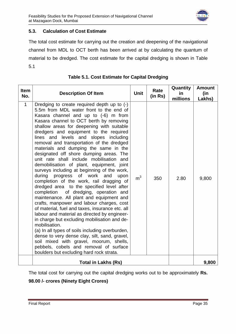
5.3. Calculation of Cost Estimate
The total cost estimate for carrying out the creation and deepening of the navigational
channel from MDL to OCT berth has been arrived at by calculating the quantum of
material to be dredged. The cost estimate for the capital dredging is shown in Table
5.1
Table 5.1. Cost Estimate for Capital Dredging
Item No.
Description Of Item Unit Rate
(in Rs)
Quantity in
millions
Amount (in
Lakhs) 1 Dredging to create required depth up to (-)
5.5m from MDL water front to the end of Kasara channel and up to (-6) m from Kasara channel to OCT berth by removing shallow areas for deepening with suitable dredgers and equipment to the required lines and levels and slopes including removal and transportation of the dredged materials and dumping the same in the designated off shore dumping areas. The unit rate shall include mobilisation and demobilisation of plant, equipment, joint surveys including at beginning of the work, during progress of work and upon completion of the work, rail dragging of dredged area to the specified level after completion of dredging, operation and maintenance. All plant and equipment and crafts, manpower and labour charges, cost of material, fuel and taxes, insurance etc. all labour and material as directed by engineer-in charge but excluding mobilisation and de-mobilisation. (a) In all types of soils including overburden, dense to very dense clay, silt, sand, gravel, soil mixed with gravel, moorum, shells, pebbels, cobels and removal of surface boulders but excluding hard rock strata.
m3 350 2.80 9,800
Total in Lakhs (Rs) 9,800
The total cost for carrying out the capital dredging works out to be approximately Rs.
98.00 /- crores (Ninety Eight Crores)

Feasibility Studies for the Proposed Extension of Navigational Channel at Mazagaon Dock, Mumbai
Final Report Page 36
CHAPTER 6 – CONCLUDING REMARKS & RECOMMENDATIONS
Presently, MDL is building several frontline warships for the Indian Navy. The ships
being constructed at MDL are required to be taken out of MDL area, for sea trials, to
the open ocean and also towards the Naval Dock (ND) for fitting of weapon sensors.
The water depth available in these stretches is about 1.5 m to 2.0 m below chart
datum (CD) and 6.0 m to 6.5 m during a tide of 4.5m. The maximum draft of fully
fitted warships proposed to be built at MDL would be about 7.2m.
In view of limited depths available near the MDL waterfront even during high tide
level prevailing in Mumbai harbour, MDL intends to create a well demarcated
navigational channel from MDL waterfront up to OCT, Mumbai with sufficient depth
for smooth plying.
CWPRS, through mathematical model and desk studies found out the most feasible
and optimum alignment for the proposed channel and their recommendations are
provided vide technical reports 5421, 5422, 5425, 5433 and 5… . The final layout of
the channel recommended by CWPRS is given in fig. 6.1.
Fig. 6.1 Final layout recommended by CWPRS

Feasibility Studies for the Proposed Extension of Navigational Channel at Mazagaon Dock, Mumbai
Final Report Page 37
Concluding remarks and Recommendations
1. The two alternative alignments of channel provided by MDL were analysed by
CWPRS. Upon detailed analysis, it is found that the flow field is not suitable for
the two alternatives proposed, which may create problem for ship maneuvering
and increase in siltation.
2. Hence, a third alignment was thus finalized and considered for deciding the
cross section of channel based on navigation studies.
3. As per ship navigation studies, the channel from MDL up to end of Kasara
channel and end of Kasara channel to OCT was considered to be deepened to
5.5 m and 6.0 m below CD of Apollo Bunder respectively.
4. The likely rate of maintenance dredging in the proposed channel will be about
1.1 million cum per annum.
5. To achieve the channel alignment and dimensions proposed by CWPRS, the
quantum of capital dredging to be carried out will be about 2.8 million cum. The
material to be dredged is silty clay / clay.
6. The approximate total cost for execution of the capital dredging to establish the
proposed channel would be approximately Rs. 98 crores.
7. The dredging may be achieved through deployment of Grab dredger since the
material is of clayey nature and considering the limitation of depth criterion.
8. The dumping of material dredged from proposed extension of navigational
channel from MDL waterfront up to OCT berth, Mumbai as per the dumping
schedule proposed by MDL( 600 cum/hour with 24 trips per day for 240 days)
may be carried out at flood dumping ground at Latitude 180 53’ 00” (±15") N
and Longitude 720 44’ 00” (±15") E during flood phase of tide only, while at
DS-3 dumping ground at Latitude 180 55’ 00” (±30") N and Longitude 720 42’
00” (±30")E during ebb phase of tide to achieve techno economically viable
dumping.
Feasibility Studies for the Proposed Extension of Navigational Channel at Mazagaon Dock, Mumbai
Final Report Page 38
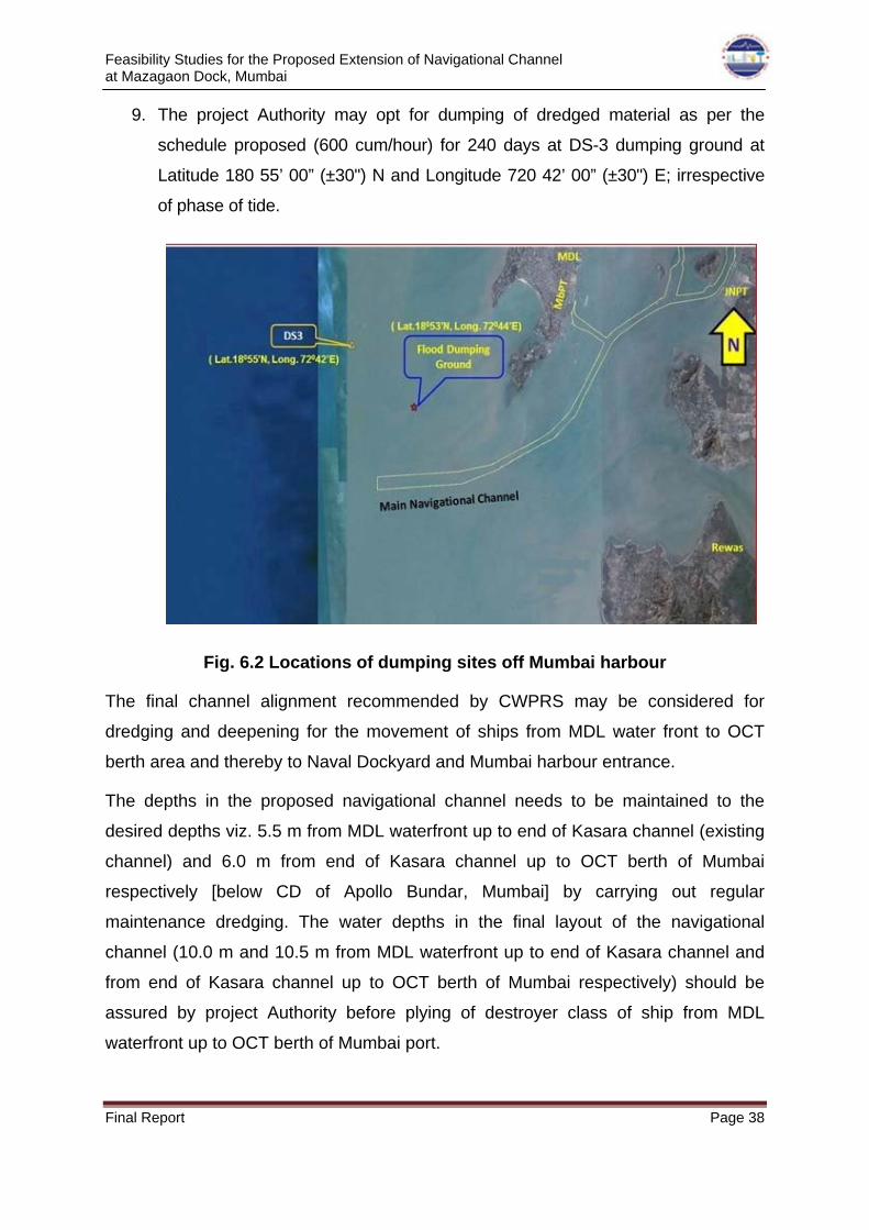
9. The project Authority may opt for dumping of dredged material as per the
schedule proposed (600 cum/hour) for 240 days at DS-3 dumping ground at
Latitude 180 55’ 00” (±30") N and Longitude 720 42’ 00” (±30") E; irrespective
of phase of tide.
Fig. 6.2 Locations of dumping sites off Mumbai harbour
The final channel alignment recommended by CWPRS may be considered for
dredging and deepening for the movement of ships from MDL water front to OCT
berth area and thereby to Naval Dockyard and Mumbai harbour entrance.
The depths in the proposed navigational channel needs to be maintained to the
desired depths viz. 5.5 m from MDL waterfront up to end of Kasara channel (existing
channel) and 6.0 m from end of Kasara channel up to OCT berth of Mumbai
respectively [below CD of Apollo Bundar, Mumbai] by carrying out regular
maintenance dredging. The water depths in the final layout of the navigational
channel (10.0 m and 10.5 m from MDL waterfront up to end of Kasara channel and
from end of Kasara channel up to OCT berth of Mumbai respectively) should be
assured by project Authority before plying of destroyer class of ship from MDL
waterfront up to OCT berth of Mumbai port.