Embed Size (px)
Citation preview

Mediterranean Archaeology and Archaeometry, Vol. 15, No 3,(2015), pp. 17-30 Copyright © 2015 MAA
Open Access. Printed in Greece. All rights reserved.
DOI: 10.5281/zenodo.18355
NOTES ON NABATAEAN CONSTRUCTION TECHNIQUES: A CRITICAL REVIEW AND INVESTIGATION
OF EL-KHAZNEH SLOTS FUNCTION
Naif A. Haddad
Department of Conservation Science, Queen Rania's Institute of Tourism and Heritage, Hashemite University, P.O. Box 3034, Amman 11181, Jordan ([email protected])
Received: 25/3/2015 Accepted: 06/05/2015
ABSTRACT
The Nabataeans were highly creative in their adaptation of the Greco-Roman construction techniques. Based on their specific natural resources and lexicon of architectural elements, the Nabataeans thus devel-oped their own techniques. Indeed, the size and elaborate nature of many of their monuments would require such innovations, as physically manifested in the two vertical rows of slots located on the recessed back face wall on either side of the façade of el-Khazneh in Petra in Jordan. These slots have been a matter of some debate on whether their function was for footholds or for scaffolding. Though the slots have been discussed in passing, no scholar has made the in-depth critical investigation in determining their proper technical and functional approach with reference to their preserved fully recorded dimensions. Thanks to a recent study using a combination of 3D laser scanner and reflector-less total station, we now have precise measurements of the well preserved individual slots. This article is concerned with the particular case of these slots. A de-tailed examination of these slots in relation to their size and depth, position and arrangement within the fa-çade, probably credits their use, both, as foot holes, and as supports for a smart and simple scaffolding struc-ture. The paper suggests and exemplifies that, these slots are part of an authentic Nabataean construction technique, and they were the foundations used to fix a wooden lightweight socket in a diagonal changeabla cantilever scaffolding. This new assumption is supported with schematic sections and illustrations showing alternative combinations of the cantilever scaffolding at different slot heights, using the embedded putlog and diagonal bracing on which the planks are held. Thus, providing the basis for further research, hopefully encouraging a further knowledge of Nabataean scaffolding construction techniques of rock-cut architecture.
KEYWORDS: Rock-cut architecture; Socketed diagonal cantilever scaffolding; Putlogs; Nabataean Architecture; Con-struction techniques; el-Khazneh.
18 NAIF HADDAD
1. INTRODUCTION Nabataean architecture reflects the collaborative
spirit of the Hellenistic and Roman periods, where architects fluidly moved among various Eastern and Western cultures, seeking the highest artistic stand-ards in both architectural design (Haddad, 1999,167-168; 2012) and construction techniques (Rababeh, 2005, 227). The Nabataean international trade and commercial activities, especially their relationship with Asia Minor, had been the major acknowledged influence on the Nabataean architectural renaissance (Al- Salameen 2008, 2011). In fact, some of the best preserved samples of late Hellenistic morphology, lies in the worn canyons of Nabataean Petra, delight-ing visitors and scholars alike with a stunning com-bination of oriental and western stylistic elements.
Many of the most monumental structures, such as the free standing Qasr al Bint temple, the rock- cut Theatre, and the funeral rock-cut structure at el-Khazneh (see, Fig. 1), were constructed at the height of the Nabataean Kingdom’s prosperity, around the last century BCE and the beginning of first century CE. (Regarding their astronomical orientation see, Liritzis et al., 2015).
However, interestingly enough is Schmidt's (2001, 388) presumption, that there is no good reason to believe that the simpler rock-cut facades, showing stronger oriental influence, would be older than the richly decorated ones like el-Khazneh. On the other hand, through recent studies of the relationship be-tween tombs carved at Petra, and the evidence of the later on dated Madāin Sālih rock-cut tombs, but also as evident from the chronological development of the earlier Macedonian tombs (Haddad, 1999; 2012) a pattern became evident whereby the larger and more complicated façade types tended to occur ear-lier than their smaller, simpler versions.
This proposed chronological façade tombs ap-proach, from complex to more simple contrasts with more traditional typologically-based chronologies, which see a linear development from simple to com-plex in façade design (Wadeson, 2010,60-65 ; 2011).
In terms of size, the facades tended to vary ac-cording to type, the general rule being that the more complicated the façade design, the larger the façade must be, as for example the case of el-Khazneh. Cer-tainly, the size was also influenced by the social sta-tus of the owner. In terms of el-Khazneh's architec-tural composition, some scholars (Lauter, 1971, 149-78; Lyttelton 1974, 53-60, 83; McKenzie 1990, 75- 77; Will and Larché 1991, Schmid 2001, 386-7; Wenning 2003, 14; Rababeh 2005, n.169; Haddad, 2012) have connected el-Khazneh with that of Palazzo delle Colonne in Ptolemais, Cyrenaica. In fact, el-Khazneh typifies the Nabataean’s distinctive baroque ap-
proach to rock- cut façade architecture, which seam-lessly merges the late Hellenistic regional school and local traditions to form a new fully developed lexi-con of architectural forms.
Figure 1. El-Khazneh, the treasury (25.3x39.1m). The slots are
located on the recessed back wall on each side of the rock- cut façade.
The rock-cut façade of el- Khazneh (shown in Fig.
1) is conceived as an independent screen set in the front of the building, rather than as an organic or logical element of the structure as a whole.
On the other hand, the Nabataeans worked in per-fect harmony with their environment, allowing the land’s unique sandstone formations to shape their equally unique construction techniques. This adapt-ability allowed the architects, quarrymen and ma-sons to be practical and economically efficient in their projects. This is not to say that the Nabataeans didn't borrow construction techniques from the wid-er Hellenistic and Roman world, but the techniques were specifically adapted to the nature of the land-scape, representing a true fusion of technique. Rababeh (2005) concluded that the Nabataeans had their own unique construction techniques, which are as distinctive as their architectural style1.
2. THE SLOTS OF PETRA’S EL-KHAZNEH: ANALYSIS OF THE BASIC FEATURES
Traces of slots are common throughout the prima-ry quarries of Petra (Shaer and Aslan, 2000, 92, 114;
Rababeh, 2005, 65-70). However the most character-istic of these can be clearly seen beside el-Khazneh (the treasury) (25.3x39.1m). The slots are located in

NABATEAN CONSTRUCTION TECHNIQUES 19
Mediterranean Archaeology and Archaeometry, Vol. 15, No 3, (2015), pp. 17-30
an inaccessible place beside el-Khazneh’s back face, on the recessed wall on either side of the façade (as shown in Fig. 1).
Figure 2. Documentation of the fine survived slots of the left
and the right side of the two vertical rows beside the El-Khazneh, in relation with the main architectural façade's ele-
ments.
Most of these slots have been preserved in good condition, while others have inevitably been eroded by water, wind and sand to the point of deteriora-tion.
As shown in Figs (1, 2), there are two vertical rows of mostly square and rectangular holes, the dimen-sion and position of which are slightly irregular. Both sets of slots start at about 12 m above the floor2. Farajat and al-Nawafleh (2005) have noted that the starting of the slots’ height is only a little above the top of the tombs carved before el-Khazneh, their up-per parts of which were cut away when el-Khazneh was carved3. Their patterns do not detract from the façade’s overall design, and seem to enhance the ar-chitectural ornaments of the second floor.
Thanks to a recent study, using a combination of 3D laser scanner and reflector-less total station, we now have precise measurements of the well pre-served the individual slots. We were able to fully record 59 slots in good condition of the left side (shown in Fig. 3), and 30 visible slots to the right side4 (shown in Fig. 4). The measurement covered the four sides (A, B, C and D) and the depth (E) of each slot, as illustrated in Fig 5.
From the 3D mesh model of the 3D scanner (Mensi GS 100)5 it was possible to measure with the same needed accuracy as was conducted by the re-flector-less total station (Leica T1800). The difference in measurements is between 0.2 - 2 cm (Haddad and Ishakat 2007, 358-361).
On the right side, their heights range from 15 - 46 cm, and their width from 15 - 35 cm. Similarly, the height on the left side ranges from 15 - 46 cm, while the width widens slightly to be between 20 – 40 cm. The detailed measurements are listed in table I and table 2 (see Appendix).
However, the cross section through each slot shows that it has a greater depth at the bottom (10-20 cm) forming triangles cut into the wall. The tops then have zero depth and blend back with the fa-çade, as shown schematically in Fig. 5.
Fig. 5 also illustrates the three categories of these slots, in relation to their dimension and depth. Most of the slots' depth at the bottom ranges from 11-15 cm, while many others range from 18 - 20 cm.
On the left side, the horizontal distance between two slots ranges from 20 to 30 cm, while the vertical distance ranges from 15 - 35 cm. On the right side, the horizontal runs from 25 - 35 cm, while the verti-cal6 measures 15 - 40 cm.
3. CRITICAL REVIEW OF SCHOLARS AND RESEARCHERS' ASSUMPTIONS OF EL-KHAZNEH SLOTS FUNCTION
Firstly, it should be clarified that it is generally agreed that, the rock-cut façades carving procedure was a relatively simple method done from the top to bottom, and that as a first step, a flat narrow smooth working surface of the façade was created in front of the desired tomb façade after quarrying away the stone of the cliff’s natural slope, followed by the carving of details (Kennedy, 1925; Parr 1968; Ham-mond 1973; Browning 1982; Rababeh, 1995, Bessac and Nehmé 2007; Haddad, 2012). Several unfinished tomb facades in Petra support this assumption, that reveal such a sequence of work.
although the question of el-Khazneh’s slots func-tion have been the topic of several studies the pres-ence of theses slots in one of the largest and most elaborate rock-cut façades in Petra remains perhaps the most queried in Nabataean architecture, as such slots are preserved at el-Khazneh’s façade (Parr 1968, 11; Bessac and Nehmé, 2007, 36).
These slots have been a matter of some debate on whether their function was for footholds or for scaf-folding. Though the slots have been discussed in passing, no scholar has made the in-depth critical investigation in determining their proper technical and functional approach with reference to their fully recorded dimensions. This section presents a critical and analytical review of the suggested hypotheses and assumptions within the field, in an attempt to develop a divergent theory about their use and their technical functional approach.

20 NAIF HADDAD
Figure 3. Detailed documentation of 59 slots of the left side of the two vertical slots’ rows, supported by photographic view
showing the left edge/side of el-Khazneh back face. Many researchers however have generally as-
sumed that the slots of el-Khazneh were holds sup-porting a scaffolding. What has not been elucidated is the specifications of how this scaffolding technical-ly worked, and the theory behind its construction.
An exception to this trend is Peter Parr (Parr, 1968, 10-11, n 28), who suggested that it is probable that these two vertical rows of holes on either side of el- Khazneh are the work of iconoclasts rather than the original builders.
Two dates were suggested by Parr for this de-facement, either sometime before 417 CE, when the
Figure 4. Detailed documentation of 30 slots of the right side of
the two vertical slots rows, spuorted by photographic views showing the right edge/ side of el-Khazneh back face.
Urn Tomb was converted to a church, or in 720-24
CE, when Caliph Yazid II sent a decree to destroy images and pictures throughout the Muslim world. Of the two explanations, Besancon (2000, 279) and Rababeh (2005, 71) believe that the latter suggestion is more likely, since the Byzantines never defaced animals.
However, Rababeh (2005, 71) states that "It is pos-sible that the cuttings could still have been made by the carvers of el-Khazneh to move during work and then re-used by iconoclasts as a device to deface the figures in a later period".

NABATEAN CONSTRUCTION TECHNIQUES 21
Mediterranean Archaeology and Archaeometry, Vol. 15, No 3, (2015), pp. 17-30
Figure 5. Three dimensional sketches of the three characteristic categories of the slots (Rectangular and Square) showing their
depth in relation with their length and width. Rejoining mainstream thought, Browning (1973,
50) in his book Petra, initially suggests that wooden scaffolding was used in carving el-Khazneh. How-ever in the fifth, new and revised edition (1982), he clarified that "there is still one other unsolved prob-lem in the Wadi al Jarra with its clumps of soft green oleander".
Browning stated that, "on the recessed walls up to the side of the Khazneh façade are two rows of verti-cal footholds rising up the full height of the monu-ment. The purpose of these cannot be determined. These footholds also occur on the walls of the quar-ries in the Wadi Siyagh and on the Attuf Ridge" (Browning 1982, 125).
McKenzie (1990, 143) stated more plainly that "there are two rows of roughly cut foot-holds on ei-ther side of the façade. Similar marks occur in the Nabataean quarry in Wadi Siyyagh".
Breaking from this line of argument, Pflüger (1995, 291-292) suggested that wooden scaffolding supported by poles was perhaps used in quarrying, though he only hesitatingly puts forward a rough schematic of the design used, shown in figure 6.
Perhaps the most weighty analysis of the slots’ function was conducted by Rababeh (2005, 65-76). He assumes that, wooden scaffolding supported by poles would be astonishing in a city like Petra, which is poor in wood.
He continues to detail a variety of specific prob-lems resulting from the use of wood, concluding that the idea that these slots were used for scaffolding to any extent is incredible (Rababeh, 2005, 71).
Though, there is no reason for believing that the Nabataean masons used wooden scaffolding sup-ported by poles, which would have required enor-mous quantities of wood to reach the top of the quarries (Rababeh 2005, 70).
Rababeh assumes that the holes are only 55 cm apart, and the depth of the holes is not sufficient to hold wooden beams for constructing this huge scaf-folding structure.
Figure 6. Wooden scaffolding suggested by Pflüger ( After
Pflüger 1995: Fig.4) Additionally, craftsmen likely had to remain on
the scaffolding for a long period to finish carving the monument, potentially up to three years7 . Those three years would have caused the wood to rot or buckle.
In order to minimize the amount of wood re-quired while maximizing the masons’ reach, Rababeh suggests instead of that carved terraces were used at Petra to create horizontal working plat-forms, and he illustrated the steps of quarrying the niches using ladder, slots and ropes ( shown Fig. 7).
More precisely, Rababeh proposes that a working platform was used in carving the different stages of el- Khazneh, and it is more likely that they used the adjacent hillside to reach the monument during the period of the work ( Rababeh, 2005, 224).
In further investigation of the building’s actual structure, Rababeh discusses two possible methods of carving. The first was to quarry the vertical sur-faces and carve the decoration separately, as op-posed to simultaneously completing both tasks.
For such major monuments as el-Khazneh, Rababeh leans toward the first method, supposing that workers may have needed to switch between levels within the quarry, even after the quarrying process had commenced (Rababeh 2005, 70 - 71).
Vertical single or double rows of hand and foot-holds, as seen on the surfaces of the primary quar-ries, thus enabled the needed rapid mobility throughout the site, while preventing slippage on the treacherous cliff sides.
In some cases, he estimates that the workers actu-ally climbed the monument with the aid of ropes, which were possibly anchored in pairs of holes higher up the cliff8.

22 NAIF HADDAD
Mediterranean Archaeology and Archaeometry, Vol. 15, No 3, (2015), pp. 17-30
Figure 7. Reconstruction drawings suggested by Rababeh show-ing the steps of quarrying ( After Rababeh, 2005: 69, Fig.3.23. b).
However, in the case of the conchoidal quarrying
of the Wadi es-Siyyagh, where the stone was extract-ed from the near-vertical central part of the sloping cliff, Rababeh states that "It was too difficult to find access from above as mentioned in the stepped quar-ries. This indicates that the masons must have used scaffolding" (Rababeh 2005, 71). Finally, contradicting Rababeh is Khairy (2011), who after the recent conducted excavations in front of el-Khazneh (Farajat and al-Nawafleh ,2005, 373–393), generally recommended that, "scaffolding was used on each of the levels of the rock-cut platform as work proceeded from the top down" (Khairy 2011,167). However, Khairy did not provide any information or specifications of how this scaffolding worked, or the method used to construct it. He only stated that, "these [levels] were accessed by the footholds, or from scaffolding". Without any clarification he only mentioned that, somewhat of a third alternative combining the two theories suggesting that "short heights of scaffolding were erected on each rock platform as work proceeded down the rock-face" (Khairy 2011, 167).
4. DISCUSSION AND RESULTS
This section thus aims to critically and methodi-cally examine the possibility of a particular wooden scaffolding technique used in el-Khazneh, while at the same time shedding light on the different se-quenced stages of cutting the two floors’ façade’s
cutting. Mainly, to undertake a task, that till now, was never accomplished.
Firstly, although the unfinished tomb facades as-sumption holds true for some of the rock hewn fa-çades where, carving was done from the top to the bottom of a façade, it cannot be taken as a general rule. Unfinished tombs found throughout Petra show also cases where carving was simultaneously done at the top and the bottom of a façade, even also detailed architectural features were carved at the same time.
Very often, in order to simplify the carving pro-cess, the chamber ceiling was executed following the lithology of the sandstone layers (Shaer 2005, 61, fig. 5, 6). Rababeh (2005, 73) also mentioned that, as indi-cated by the unfinished tombs of el-Habis and at Caunus in Caria, the carving of the main chamber was carried out simultaneously with that of the main façade at the same level. However, carving simulta-neously the rock-cut facade gave also the opportuni-ty to test the quality and stability of the lithology of the sandstone layers. In fact, the excavating, carving, and finalizing of many tombs in Petra and Mada’in Saleh were carried out at the same time as the inter-nal main chamber with its loculi, as seen from the unfinished tomb to the west of the temple of Qasr el-Bint in Petra (Khairy 2011,167).
On the other hand, if one considers that the slots were created before the carving and finalizing details stage of the pediment, capitals, cornices, and the in-ternal main chamber, or even simultaneously with the main façade at the same level, the slots’ general arrangement and formation would be cut in relation to the envisioned architectural elements, starting from the broken pediments of the second floor and stopping slightly below the capitals of the ground floor.
The three slots categories shown in figure 5, with their blatant differences in dimension, arrangement, and depth (as shown in table 1 and 2, see Appendix) cast doubt on the previously assumed slots’ foothold function only, leading one to suppose that there was perhaps an intention behind their seemingly irregu-lar design.
If we are to accept that, the slots were only foot-holds, the significant variety in their dimensions and formation requires considerable scholarly attention. Differences of more than 20 cm in height and width, and 8-10 cm in depth are not accidental, and must be accounted for in any explanation.
The quite regular formation of the slots at the in-ner Siq (Shaer and Aslan 2000, 114) quarry (shown in figure 8) perhaps underlines the intentionality of el- Khazeneh’s irregularity, and unsurprisingly scholars have more unanimously agreed upon the former slots’ use as footholds (Shaer and Aslan 1997, 223-4).

NABATEAN CONSTRUCTION TECHNIQUES 23
Figure 8. The quiet regular vertical formation of the slots at the
quarry at the inner Siq (Shaer and Aslan 2000, 114, fig 3). Perhaps even more extraordinary is the sheer dis-
tance between slots, which range from 15 - 40 cm (Haddad and Ishakat, 2007, 358), and the irregular height between the holes would also likely be un-comfortable for a person climbing the steep slopes of the cliff.
Yet the vertical distance from the base of one hole to that of the next is approximately 25 -45 cm, while some reach heights up to 35-45 cm, might making ascension by any worker a little treacherous. The rather large width of many of these slots would seem also extraordinary to be used only for a human foot, and to prevent workers from properly bracing their foot while climbing.
The average human’s vertical reach, a suitable height between slots would be around 25-30 cm, while the width of the human foot is about 10-12 cm. Even if the suitable width is expanded to 15-20 cm, that is still significantly smaller than the majority of slots, which range from 25-35 cm and reach up to 38-45 cm in width. Though, the question remains, why to cut these slots with these obvious differences and variations in dimensions and arrangements.
As Rababeh and Browning concluded, the slots' use as purely footholes only is thus weak and unlike-ly, even this hypothesis and argument was weak yet when it was first used by Peter Parr. What then of the wooden scaffolding theory? Is it any more plau-sible?
In Petra, wood was unquestionably an extremely valuable structural material, as trees were rare in the arid desert climate. Kanellopoulos (2004, 221) has a lengthy discussion on Nabataean construction meth-ods in the light of the limited timber resources and
working with sandstone. He examined the structural issues and their connection to the local geology, with consideration to environmental and economic fac-tors. However, many examples show that the Nabataeans used wood in their monuments in vari-ous situations, if sparingly9.
For example, there are similar slots found in the interior walls of the Obelisk tomb (shown in figure 9). At the back wall (5.85m) of the squared space (5.9x5.7m), there is a broad recess (2.9x1.7x 3.2m) starting at 0.2 m above the floor.
Figure 9. Similar cut slots to el-Khazneh from the second tomb level at the back wall of the inner space at the Obelisk tomb. In the middle of the two sides of this recess width,
and at the height of 2 m approximately, there are two slots at each side that have the same section as the slots of el-Khazneh, which were likely used to fix wooden beams which supported a wooden shelf in the recess.
On the other hand, one should also consider the differing times required for carving such monument, depending upon its size and the richness of the or-namental elements. The architect had in his mind that, a 39 meter scaffolding supported by a pole structure, as suggested by Pflüger, is out of question for a structure of the size of el-Khazneh; it is time consuming and insufficient, compared to the rock-

24 NAIF HADDAD
Mediterranean Archaeology and Archaeometry, Vol. 15, No 3, (2015), pp. 17-30
cut horizontal working platforms proposed by Rababeh.
For the Nabataeans, it would actually have been time consuming, cumbersome and expensive to erect such scaffolding, especially with the huge number of monuments in Petra (more than eight hundred). In-deed, a 39 meter scaffolding structure would con-sume a forest full of timber, an extremely wasteful use of such a rare commodity10.
4.1 Investigation of the Slots Function by the So Called Socketed Cantilever Scaffolding
As fully built scaffolding structures remain equal-ly unlikely, the question of the slots’ functional ap-proach still remains.
The key seems to be in the irregularity of the structure. This irregularity may therefore indicate an adjustability built into the structure, enabling modi-fication according to the desired height of the worksite.
The following thus argue the potential of using the slots for fixing a simple lightweight system of changeable wooden cantilever scaffolding.
The slots of el-Khazneh form almost a vertical line, though some slots appear slightly curved and outside of the main vertical line, following instead the original line cut into the rest of the mountain face on either side of el-Khazneh.
In contrast, within the pairs of slots, most are aligned horizontally (shown in figures 3, 4). In fact, one can observe that the combination of the afore-mentioned cutting line and the remaining uncut back wall of the façade define these vertical and hor-izontal lines, even in many cases the distance be-tween some of these slots.
Essentially, the depth of the slots is more than suf-ficient to hold wooden beams for constructing and supporting a comparatively lightweight changeable scaffolding structure.
According to the conducted measurements, where the detailed measurements are listed in table I and table 2 (see Appendix), the survived depth of the majority of the slots on either side of el-Khazneh is between 11-15 cm, while many others is between 18-20 cm. According to Khairy (2011, 167) the depth of the slots vary from 15 to 24 cm. However, some variations in slot depth can be accounted for by the effects of the weathering, though even in current conditions the slots could support the necessary wooden beams.
Though, we can explain the existing variations re-garding the three categories of the slots (shown in Fig. 5), in relation to their dimension and depth, while they were not originally designed for foot-holds only, but furthermore for holding also wooden beams.
Due to the actual cut shape of the sections, we can suggest that one edge of a horizontal wooden beam was fixed inside the slot base, preventing it from moving upward. Even to ensure that this edge will not move up, it can be more secured by a small tri-angular wooden wedge. The other free edge of this beam was stabilized by another angled beam resting in a lower slot fastened by metal pins or even tied by a small piece of rope.
Furthermore, one can explain that the variety in slots' depth, in relation to their height, would have enabled workers to vary the vertical support beam’s angle from the lower slots, as schematically illustrat-ed in figures 10,11.
These schematic sections propose alternative combinations of the cantilever scaffolding at differ-ent slot heights, using the embedded putlog and di-agonal bracing on which the planks are held. This arrangement also allows for more flexibility in the wooden beam lengths which could reach more than 1m (as shown in figures 10, 11). This suggested tech-nique forms a lightweight changeable (temporary) wooden scaffolding system.
In fact, at a huge monument like el-Khazneh, the duration of time and the prior coordination required to finish such intricate carving would predicate the construction of such a lightweight scaffolding sys-tem.
In other words, in order to accomplish the vast quantities of detailed craftsmanship, workers would have to be able to move freely throughout these needed working levels of structure for extensive pe-riods of time.
Thus, the intelligent architect of el-Khazneh de-veloped and implemented an adaptable and change-able lightweight socketed cantilever scaffolding sys-tem, where on those horizontal beams rested the planking from which the work was carried out, thus supported the workers’ varied movements through-out the massive structure’s long construction.
As briefly mentioned above, the system consisted of two wooden beams underlying the platform, which was supported from below by some angled putlogs (as shown in Figs. 10, 11).
NABATEAN CONSTRUCTION TECHNIQUES 25
Mediterranean Archaeology and Archaeometry, Vol. 15, No 3, (2015), pp. 17-30
Figure 10. Schematic sections showing the potentiality of some alternative combinations of the cantilever scaffolding at differ-ent slot heights, using the embedded putlog and diagonal brac-
ing on which the planks are held.
Analogous approach of this temporary Nabataean adjustable scaffolding, socketed to the masonry walls to replace the support of the wooden poles, was successfully used in the Greco-Roman world, as it is evident in many huge and high Roman walls.
These scaffoldings were presented and discussed by Adam (1984, 87-90, Fig. 182, 190) in his book Ro-man Construction: Material and Techniques, where the Roman builders used putlog scaffolding socket-
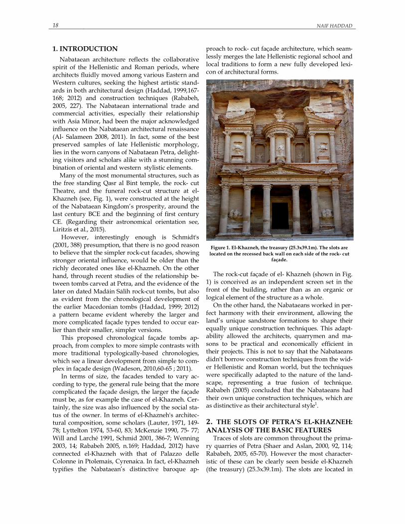
ed to the masonry walls as the vertical support to replace the support of the wooden poles (as shown in Fig. 12).
Figure 11. Three dimensional schematic illustration showing the suggested scaffolding technique of using lightweight changea-ble wooden scaffolding system (socketed cantilever scaffold) ,
and some possible working levels. Two Roman scaffolding schemes were possible;
either the vertical outer support by poles or the re-placed poles by series of triangular trusses set against the wall face ( as shown in Fig. 12). The put-log was strengthened on the face of the wall with a short vertical support and a diagonal brace, from one vertical support to another to increase the stabil-ity of the cantilevered scaffolding (Wright 2009, fig 79).
The so called Roman socketed cantilever scaffold-ing, usually had putlogs that could go through the wall and support the floor from both sides of the wall.
To economize on wood and at the same time to achieve a complete stability, series of holes were made as they progressed in the construction of the Roman masonry walls. The outer poles and the aligned masonry holes supported the scaffolding.

26 NAIF HADDAD
Mediterranean Archaeology and Archaeometry, Vol. 15, No 3, (2015), pp. 17-30
As in the case of el-Khazneh slots, it could also make away totally the poles if the wall was high enough, to support the embedding of the putlogs from one or two sides (Dodgeq, 1984, 191)11.
Actually, the importance of this socketed cantile-ver scaffolding increased as the scaffolding rose higher. Finally, when the wall was completed, the scaffolding was removed, leaving behind the holes.
Figure 12. Roman socketed scaffolding: the outer vertical sup-
port by poles ( 1- left); socketed cantilever scaffolding by trian-gular trusses (2-right) ( After Adam 1984, 87, fig 182).
However, in the case of el-Khazneh slots there is
no need for the short vertical support. This while the supporting diagonal brace could be inserted and fixed entirely due to the particular slot cut and depth.
In conclusion, by accepting this suggested tech-nique of the diagonal socketed cantilever scaffold-ing, we should also agree that this technique may have been applied to other parts of el-Khazneh fa-çade, such as between the engaged columns and cap-itals. While carving the three bays for example, slots may have been temporarily cut into the façade, being later sanded away.
Finally, we might conclude that the architect wise-ly calculated and designed all the different progres-sion sequenced stages of implementation before starting any work, as suggested (from stage 1 to 11) (as shown in Fig. 13).
It is also logical to assume that the Nabataean masons, would have been trained in and had mas-tered the necessary skills before they were allowed to participate in such very delicate and sophisticated construction tasks (Khairy, 2011, 168).
Figure 13. Photographic illustration showing the probable dif-ferent sequenced stages (1-11) for the cutting order and final
decoration finishing of el-Khazneh two floors' façade. 5. SUMMARY AND CONCLUDING RE-MARKS Generally we can assume that, the Nabataeans de-veloped their own construction techniques in ways specific to the particularity of structures built in Pet-ra, taking into consideration the economical and practical aspects. Their techniques show a high level of creativity in adapting and finding technical solu-tions for carving a rock-cut monument such as el-Khazneh.
Indeed carving a monument as grandiose and im-posing as el-Khazneh required significant strategic planning and innovation. The scarcity of wood and the plethora of sandstone presented broad challeng-es to the architect, challenges which were surmount-ed only by following a plan which laid out in a high-ly detailed fashion of the carving order and final decoration finishing processes, and their subsequent implementation (shown in Fig. 13).
The plan also had to coordinate the overwhelming number of labourers required to complete the pro-ject, including the teams of quarrymen, sculptors and painters. To a large extent, the needed mobility was facilitated by a series of slots, functioning as footholds and as the foundation for a lightweight changeable socket in diagonal cantilever scaffolding system, as evidenced by the slots’ arrangement, di-mensions and irregularity.
Due to the slot’s cut-in shape, one edge of a hori-zontal wooden beam remains fixed inside the hole without it sliding upward, while the other free edge of the beam is stabilized by another angled beam resting in a lower slot, as shown schematically in

NABATEAN CONSTRUCTION TECHNIQUES 27
Mediterranean Archaeology and Archaeometry, Vol. 15, No 3, (2015), pp. 17-30
figure 10, 11. Upon studying this arrangement, one could feasibly suggest alternative support structures for the platforms.
It is shown here that, contrary to some recent sug-gestions, the genius architect created a unique light-weight and moveable wooden socketed diagonal cantilever scaffolding system, relying on a few thin beams and strategically cut slots. Although this scaf-folding technique concept was initially conceived and thus borrowed from the Greco-Roman world (shown in figure 12), because of the particular land-scape formation in Petra and the level of detailed sculpture, the painted decorated stucco and materi-als available therein, the result is purely Nabataean.
Most critically, the suggested socketed cantilever scaffolding construction technique was developed and implemented solely by the Nabataean builders and architects themselves.
An acceptance of this scaffolding technique leads to the assumption that this practice might have been applied in other parts of el-Khazneh façade, even in other rock-cut facades in Nabataean Petra, though the traces have been removed. Said scaffolding tech-nique provides the basis for further research, hope-fully encouraging a further knowledge of Nabataean construction techniques. Scholars will thus be able to piece together a more complete picture of Nabataean architectural scaffolding construction methods.
6. APPENDIX The following Tables 1, 2 are new results using 3D Laser scanner and total station (based on Haddad and Ishakat 2007, 358-361,
tables 1, 2, 3, 4).
Table 1. Measurement recorded of 59 slots on the left side of the two vertical rows beside the El-Khazneh.
Combination of the measurement recorded using 3D Laser scanner and total station
Slot ID A B C D E 1 230 170 225 195 90
2 213 - 210 - 46
3 310 200 317 210 82
4 350 330 380 290 150
5 300 430 400 470
6 240 360 280 350 150
7 350 320 340 400
8 380 250 390 280 187
9 420 390 416 400 -
10 440 200 450 150 -
11 380 225 360 220 134
12 410 340 420 300 161
13 360 360 427 328 174
14 430 329 430 387 181
15 254 270 249 282 158
16 290 460 280 330 184
17 290 400 280 400 195
18 332 389 370 426 191
19 312 310 320 373 190
20 351 378 350 380 169
21 260 350 280 349 201
22 280 152 384 380 200
23 250 401 310 390 160
24 286 401 252 413 122
25 400 408 380 420 194
26 230 320 230 318 150
27 310 380 327 400 207
28 270 409 300 401 140
29 200 354 262 307 82
30 321 397 326 449 198
31 260 270 255 274 66
32 230 245 246 268 37
33 250 142 243 109 100
34 198 176 205 110 113
35 250 350 248 330 180
36 280 340 270 328 150
37 200 250 226 237 115
38 137 271 200 265 145
39 220 264 224 276 157
40 210 228 250 221 127
41 200 256 200 270 137
42 197 270 265 310 163
43 205 302 205 294 156
44 200 240 203 250 117
45 202 267 190 270 160
46 267 310 260 305 117
47 270 346 259 340 122
48 255 316 264 310 110
49 250 210 270 240 100
50 240 321 264 375 128
51 219 335 247 390 112
52 319 346 300 346 166
53 320 337 305 324 117
54 326 351 340 402 150
55 290 330 210 350 102
56 320 455 264 478 150
57 400 310 237 263 100
58 280 270 330 270 114
59 300 290 390 330 55

28 NAIF HADDAD
Mediterranean Archaeology and Archaeometry, Vol. 15, No 3, (2015), pp. 17-30
Table 2. Measurement recorded of 30 slots of the right side of the two vertical rows beside the El-Khazneh Combination of the measurement recorded us-
ing 3D Laser scanner and total station Slot ID
A B C D E 1 220 140 180 151 90
2 240 140 230 140 -
3 180 220 190 297 121
4 170 225 164 220 90
5 230 320 240 328 120
6 210 265 210 282 85
7 260 290 267 254 120
8 250 293 300 290 100
9 237 260 277 302 134
10 280 294 350 298 118
11 300 242 320 212 110
12 260 280 310 300 123
13 340 266 330 287 140
14 413 257 359 319 90
15 345 243 315 278 80
16 257 298 270 325 130
17 256 370 301 337 95
18 277 363 272 364 90
19 220 394 247 382 100
20 271 340 285 334 110
21 220 375 275 316 141
22 350 260 340 400 117
23 273 402 247 490 141
24 330 420 370 369 140
25 300 440 291 449 112
26 235 220 370 110 90
27 290 295 318 166 107
28 230 200 230 260 122
29 240 180 267 196 -
30 290 363 302 281 -
REFERENCES
Adam, J-P.(1984) La construction romaine : Matériaux et techniques. A éd. Paris: Picard. Bessac, J-C. and Nehmé, L. ( 2007) Le Travail de la pierre à Petra — Technique et economie de la taille rupestre, Par-
is:Éditions Recherche sur les civilisations. Al-Salameen, Z (2008) The Nabateans and Lycians. Mediterranean Archaeology and Archaeometry, Vol. 8, No. 2,
21-29. Al‐Salameen, Z. (2011) The Nabataeans and Asia Minor, Mediterranean Archaeology and Archaeometry, Vol. 11,
No. 2, 55‐78. Besancon, A. (2000) The Forbidden Image. Chicago: Chicago University Press. Browning, I.( 1973) Petra. 1st ed. London: Chatto and Windus. Browning, I. (1982) Petra. Rev. ed. London: Chatto and Windus. Brünnow, R.E. and von Domaszewski, A. (1904) Die Provincia Arabia. Vol. 1, Strassburg: Trübner. Dalley, S. and Goguel, A. (1997) The Sela’ Sculpture: a New-Babylonian Rock Relief in Southern Jordan, An-
nual of the Department of Antiquities of Jordan, Vol. 41, 169-77. Dodgeq, H. (1984) Building Materials and Technique in the Eastern Mediterranean from the Hellenistic Peri-
od to the Fourth Century AD. PhD Thesis. University of Newcastle. Farajat, S. and Nawafleh, S. (2005) Report on the al-Khazna courtyard excavations at Petra (2003 Season),
Annual of the Department of Antiquities of Jordan, Vol. 49, 373–393. Kanellopoulos, Ch.(2004) The Temples of Petra: An Architectural Analysis, Archäologische Anziger ,Vol. 1,
221-239. Kennedy, A. (1925) Petra: Its History and Monuments. London: Country Life. Haddad, N. (1999) Macedonia, Alexandria, Petra: Tomb Architecture, In: International Congress, Alexander The
Great: From Macedonia to the Oikoumene, Veria, 27–31. 5. 1998 , Nomarchiake Autodioikese Hemathias, Greece, 161-171.
Haddad, N. (2012) Aspects of the Particularity and Creativity of the Nabataean Architectural Culture during the Late Hellenistic and Roman period, In The First International Conference of the Nabataean Culture, Petra: 5 – 8 May 2012.(In press).
Haddad, N. and Ishakat, F. ( 2007) 3D Laser Scanner and Reflectorless Total Station: A Comparative Study of the Slots of El-Khazneh at Petra in Jordan, In The International Archives of the Photogrammetry, Remote Sensing and Spatial Information Sciences, 36,5/C53, (October 2007), 356- 361.
Hammond, P.C. (1973) The Nabataeans – Their History, Culture and Archaeology. Gottenburg: Paul Äströms. Khairy, N. (2011) The Mada’in Saleh Monuments and the Function and Date of the Khazneh in Petra, Pales-
tine Exploration Quarterly, Vol. 143, No. 3, 167–175.

NABATEAN CONSTRUCTION TECHNIQUES 29
Mediterranean Archaeology and Archaeometry, Vol. 15, No 3, (2015), pp. 17-30
Kühlenthal, M. and Fisher, H. (2000) Petra. The Restoration of the Rockcut Tomb Facade: German-Jordanian Project for the Establishment of a Conversation Center in Petra. Munich: Karl M. Lipp.
Lauter, H. (1971) Ptolemais in Libyen: Ein Beitrag zur Baukunst Alexandrias, Jahrbuch des Deutschen Archäo-logischen Instituts , Vol. 86, 149-78.
Liritzis, I, Alotaibi, F.M, Castro, B, Drivaliari, A (2015) Nabatean tombs orientation by remote sensing: Provi-sional results. Mediterranean Archaeology & Archaeometry, Vol.15, No.3, 289-299. Lyttelton, M. (1974) Baroque Architecture in Classical Antiquity. London: Thames and Hudson. McKenzie, J.(1990) The Architecture of Petra. Oxford: Oxford Univ. Press. Netzer, E.( 2003) Nabatäische Architektur. Mainz: von Zabern. Parr, P. (1968) The Investigation of Some ‘inaccessible’ Rock-cut Chambers at Petra. Palestine Exploration
Quarterly , Vol. 100, 5-16. Pflüger, F. (1995) Archaeo-Geology in Petra, Jordan. Annual of the Department of Antiquities of Jordan, Vol. 39,
281-97. Rababeh, Sh. M. (2005) How Petra was Built, British Archaeological Reports International Series 1460. Oxford. Schmid, S. (2001) The Nabataeans: Travellers between Life Styles, Levantine Archaeology I. The Archaeology of
Jordan, 367-426. ed. B. MacDonald, R. Adams, and P. Bienkowski. Sheffield: Sheffield Academic Press.
Shaer, M. (2005) The Decorative Architectural Surfaces of Petra, PhD Thesis, Technische Universität München.
Shaer, M. and Aslan, Z. (1997) Architectural Investigation on the Building Techniques of the Nabataeans with Reference to Tomb 825. Annual of the Department of Antiquities of Jordan, Vol. 41, 219-31.
Shaer, M. and Aslan, Z. (2000) Nabataean Building Techniques with Special References to the Architecture of Tomb 825 (Tomb of Fourteen Graves), eds. Kühlenthal and Fisher, 89-109.
Wadeson, L. (2010) The Chronology of the Façade Tombs at Petra: a Structural and Metrical Analysis, Levant, Vol. 42, No. 1, 48-69.
Wadeson, L. (2011) Nabataean tomb complexes at Petra: new insights in the light of recent fieldwork. http://www.ascs.org.au/news/ascs32/Wadeson.pdf
Wenning, R. (2003) The Rock-Cut Architecture of Petra”, Markoe, 133-43. Will, E. and Larché, F. (1991) Iraq Al-Amir, Le château du Tobiad Hyrcan. Paris: Libraire Orientaliste Paul
Geuthner. Wright, G.R.H. (2009) Ancient Building Technology, Vol. 3, Brill. FOOTNOTES 1 "it appears that the architectural elements were derived mainly from outside contact, while local materials determined the actual construction techniques", (Rababeh 2005, 227). 2 According to Khairy (2011, 167), the slots begin at about 11 m above the rock-cut platform in front of the Khazneh. Ac-cording to Rababeh (2005, 71), the slots start at 10 m above the floor, and reach only as far as the eagle acroterion of the upper order. 3 These tombs included one directly in front of the present rock-cut steps to el-Khazneh, Tomb 62D (the ‘Window Tomb’) and its pediment still survives. It was carved before the tomb to its left, Tomb 62E (the ‘Staircase Tomb’) which was not completed inside and was apparently a Hegr Tomb type, (Farajat and al-Nawafleh 2005, 378-380). 4 The study used a 3D laser scanner (Mensi GS 100) to build a 3D mesh model, and a modern reflector-less total station (Leica). For the precise measurement of the slots, refer to Table 1, 2, 3, 4, Haddad and Ishakat 2007, 358-361. 5 TLS medium-range time-of-flight MENSI GS100; panoramic field of view of 360° (horizontal) and 60° (vertical), 5000 points per second. This scanner incorporates an internal colour calibrated video camera that has a maximum resolution of 768 x 576 pixels. The standard deviation of a single distance measurement is 6 mm at 100 m. 6 According to Rababeh (2005, 71), the distance between the adjacent rows varies from 30 to 45 cm. The height and width of the slots range from 25 to 30 cm. The vertical distance from the base of one step to that of the next is approximately 55 cm. A vertical section through one slot shows that it has a greater depth at the bottom, c.10 cm, than at the top, zero. 7 According to Rababeh (2005, 71), the DGTZ needed two years simply to carry out the restoration of the Tomb 825. On the basis of discussions with Bedoul stone workers, and his own experience as an architect, Rababeh calculates that "it would have taken approximately three years to complete el-Khazneh". 8 According to Rababeh (2005, 70-71) this method was used by Dalley and Goguel (Dalley and Goguel 1997, 169-77), to explore the Neo-Babylonian rock relief of Sela’, 50 km north of Petra, as part of their study, it was to find out how access was obtained and what kind of scaffolding had been used to carve the relief. Rababeh believes that the technique of us-ing ropes for scaling cliffs was traditional in the Edomite area and could have been continued by the Nabataeans, and
30 NAIF HADDAD
Mediterranean Archaeology and Archaeometry, Vol. 15, No 3, (2015), pp. 17-30
there is also the possibility of letting rope down from the top (Fig. 3.23b). Rababeh assumes that, if the cliff surface is very smooth and steep, footholds can be cut. 9 In Petra, wood traces are sometimes left in both freestanding buildings and rock-cut monuments as has been noted at Qasr Bint , Wadi Ram, Mampsis, Qasr Rabbah, Edh-Dharih and Qasarwat. For example, wooden beams ran north-south on the level of the roof of the cella of the Qasr el-Bint, while in the “Great Temple”, the reconstructed parts of the exterior wall contain a wooden course similar to that of the Qasr el-Bint. For more examples see Kanellopoulos, (2004, 222) and Rababeh (2005, 46-47). 10 Rababeh (2005, 71) mentioned that "to carry the weight of the masons and the quarried blocks, a huge quantity of wooden beams would have been needed to construct firm scaffolding for el-Khazneh". He supported this argument by the example of the DGTZ steel scaffolding of the Tomb 825 (Kühlenthal and Fischer 2000), "One can imagine the amount of wood needed by looking at the DGTZ steel scaffolding, which was constructed to enable conservation work to be car-ried out on the façade of the rock-cut monument adjacent to the Tomb 825. Ten levels of steel were used to secure the scaffolding, (shown in Fig. 3.25b). If the structure had been built of wood a much greater volume of material would have been required, since the tensile strength in a wooden beam is less than that in a steel beam of same cross section of DGTZ scaffolding are about 2 m apart". 11 According to Dodgeq (1984, 191), in some cases the putlogs were actually anchored within the fabric of the wall, some-times going right through, for instance, in Gaul in the 'Temple of Janus' at Autun, Plate 126, putlog holes are particularly in evidence at the springing line of vaults.