Embed Size (px)
Citation preview

Nose Cone &Fin Optimization
Tripoli MinnesotaGary Stroick
January 2011

Copyright © 2011 by Off We Go Rocketry 2
Purpose
Focus is on drag optimization to maximize rocket performance!

Copyright © 2011 by Off We Go Rocketry 3
Agenda
• Definitions• Mission Parameters• Nose Cone Design• Fin Design• Summary• Appendices• References & Web Sites

Copyright © 2011 by Off We Go Rocketry 4
Definitions1
• Drag Coefficient• Parasitic Drag
• Form/Pressure/Profile Drag− Dependence upon the profile of the object− Base Drag
– Due to Boundary Layer separation at base of airframe/fins• Skin Friction (Viscous) Drag
− Friction of the fluid against the skin of the object• Interference Drag
− Incremental drag above sum of all other drag components. Created at protrusion intersections.
• Induced (Lift-Induced) Drag• Due to redirection of airflow
• Wave (Compressibility) Drag• Due to shockwaves when moving near or above the speed of
sound (typically leading & trailing edges)• Rotational Drag
• Circumferential velocity from roll will thicken boundary layer and result in increased drag
Copyright © 2011 by Off We Go Rocketry 5
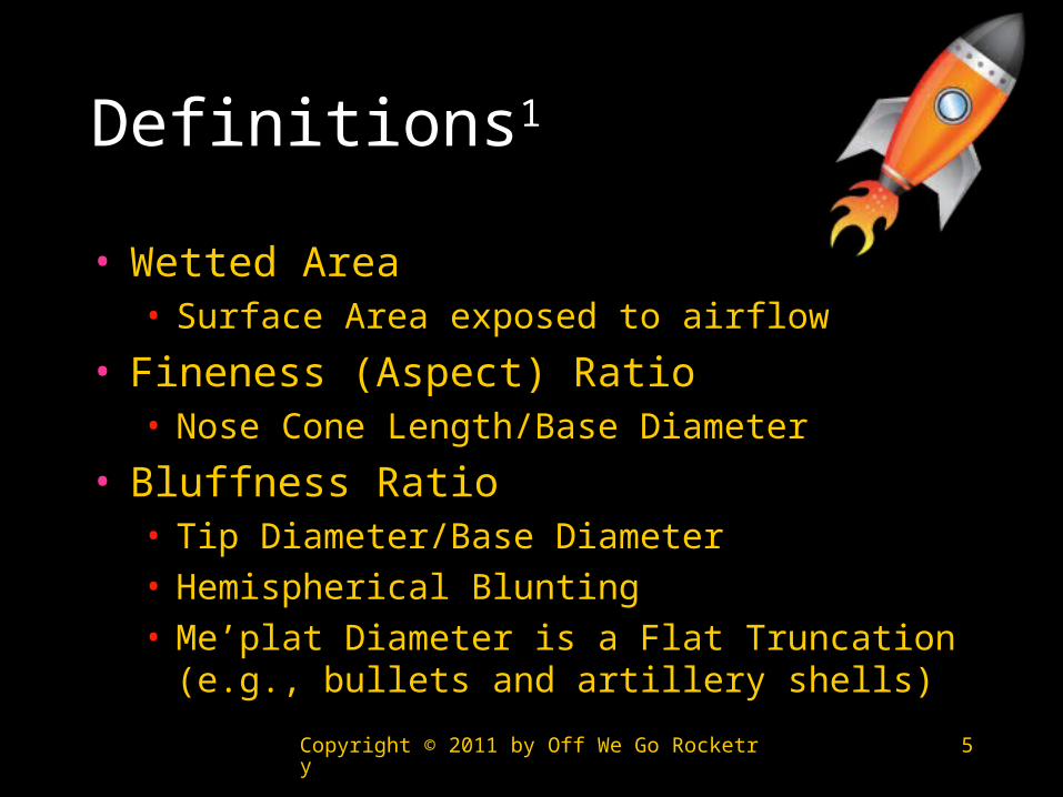
Definitions1
• Wetted Area• Surface Area exposed to airflow
• Fineness (Aspect) Ratio• Nose Cone Length/Base Diameter
• Bluffness Ratio• Tip Diameter/Base Diameter• Hemispherical Blunting• Me’plat Diameter is a Flat Truncation (e.g.,
bullets and artillery shells)

Copyright © 2011 by Off We Go Rocketry 6
Definitions1
• Laminar Boundary Layer• Fluid streams move in parallel (negligible transfer of
momentum)• Turbulent Boundary Layer
• Fluid streams transverse with velocity variations around an average value
• Boundary Layer Separation• Boundary layer separates from object’s surface
creating an effective profile• Reynolds Number
• Dimensionless ratio of inertial / viscous forces• http://www.grc.nasa.gov/WWW/BGH/reynolds.html

Copyright © 2011 by Off We Go Rocketry 7
Definitions1
• Aspect Ratio (AR)• Fin Span / Average Fin Cord
• Effective Aspect Ratio• Working AR due to Airflow Effects
• Taper Ratio• Tip Cord / Root Cord

Copyright © 2011 by Off We Go Rocketry 8
Definitions
• Thrust Profile• Thrust vs. Time Curve
• Velocity Definitions• Subsonic: < .8 Mach• Transonic: .8 to 1.2 Mach• Supersonic: 1.2 to 5 Mach• Hypersonic: > 5 Mach
Copyright © 2011 by Off We Go Rocketry 9
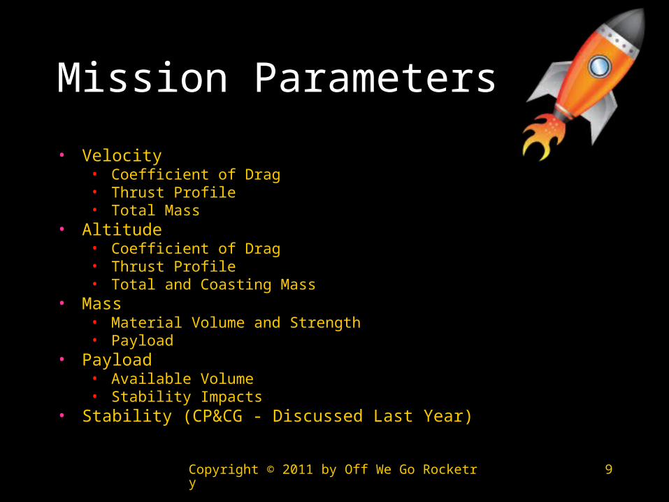
Mission Parameters
• Velocity• Coefficient of Drag• Thrust Profile• Total Mass
• Altitude• Coefficient of Drag• Thrust Profile• Total and Coasting Mass
• Mass• Material Volume and Strength• Payload
• Payload• Available Volume• Stability Impacts
• Stability (CP&CG - Discussed Last Year)

Copyright © 2011 by Off We Go Rocketry 10
Nose Cone Design
• Mission Dependent Variables• Payload• Stability (CP, CG)
• Independent Variables• Atmospheric Density• Temperature• Wind Conditions• Surface Finish• Angle of Attack

Copyright © 2011 by Off We Go Rocketry 11
Nose Cone Design
• Assumptions• Zero Angle of Attack• Constant Surface Finish• No Roll• No Aerodynamic Heating Effects

Copyright © 2011 by Off We Go Rocketry 12
Nose Cone Solutions
Subsonic1
1. Elliptical
Transonic4
1. LD-Haack (Von Karman)2. X½ Power Series3. LV-Haack (< Mach 1)
Supersonic7
1. Eggers Minimum Drag2. X¾ Power Series
Hypersonic8,9,10
1. Love Minimum Drag2. X.6 Power Series

Copyright © 2011 by Off We Go Rocketry 13
Fineness Ratio6,7
• Increasing Fineness Ratio• Decreases Wave Drag• Increases Skin Friction
Drag• Optimum Ratio is
approximately 5

Copyright © 2011 by Off We Go Rocketry 14
Bluntness Ratio2,3,5
• Optimal ratio is .15• Provided length
remains constant
• Applicability dependent upon fineness ratio and velocity• Fineness ratio ≤ 5• Below Hypersonic

Copyright © 2011 by Off We Go Rocketry 15
Coefficient of Drag (CD)Subsonic1
• Primarily Skin Friction Drag• Minimal Pressure Drag• No Wave Drag• No Interference Drag• No Induced Drag• Elliptical
• Fineness Ratio of 2

Copyright © 2011 by Off We Go Rocketry 16
Coefficient of Drag (CD)Transonic4
• Wave Drag Increases Substantially• Pressure Drag becomes Significant• Fineness Ratio of 5 is Critical
1
0.8 1.0 1.2 1.4 1.6 1.8 2.0
1 1
1
1
1 1
1
1
2 2
2
2
2
2
22
2 2
3
3
3
3
3
3
3
MACH NUMBER
4
4Tangent Ogive
Conical
LV-HAACK
Von Karman (LD-HAACK)
Parabola
3/4 Parabola
1/2 Parabola
x3/4 Power
x1/2 Power
Comparison of drag characteristics of various nose shapes in the transonic-to-low Mach regions. Rankings are: superior (1), good (2), fair (3), inferior (4).

Copyright © 2011 by Off We Go Rocketry 17
Coefficient of Drag (CD)Supersonic7
• Pressure Drag Decreases
• Wave Drag Decreases
• Fineness Ratio of 5 is Critical

Copyright © 2011 by Off We Go Rocketry 18
Coefficient of Drag (CD)Hypersonic8,9,10
• X.6 Power Series• Fineness Ratio of 5 or
6
• Varies with Fineness Ratio
• No Blunting
Copyright © 2011 by Off We Go Rocketry 19
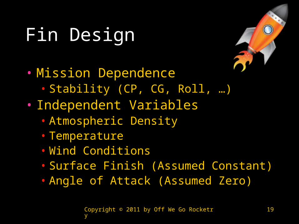
Fin Design
• Mission Dependence• Stability (CP, CG, Roll, …)
• Independent Variables• Atmospheric Density• Temperature• Wind Conditions• Surface Finish (Assumed Constant)• Angle of Attack (Assumed Zero)
Copyright © 2011 by Off We Go Rocketry 20
Fin Optimization
• Minimize Drag• Maintain Structural Integrity
• Minimize Divergence• Minimize Bending-Torsion Flutter• Minimize Mass
• Maximize Fin Joint Strength• Maintain Passive Stability

Copyright © 2011 by Off We Go Rocketry 21
Fin Drag Optimization
• No General Solution Unearthed• Computational Models Exist at Subsonic,
Transonic, and Supersonic Speeds
• Solution Factors• Velocity• Density• Lift Requirements (Corrective Moment) at
Angles of Attack• …
• Structural Strength

Copyright © 2011 by Off We Go Rocketry 22
Fin Count11
• Fin Count > 3• Skin Friction Drag
Increases• Interference Drag
Increases up to Mach 1.35
Fin Count → 3 but not always …

Copyright © 2011 by Off We Go Rocketry 23
Fin Tip Vortices1
• Vortices alter Fin Effective Aspect Ratio• Positive or Neutral Ratio Desired
• Lower Angles of Attack for Given Lift (Increases Corrective and Damping Moments)
• Lower Induced Drag for Given Lift• Desire Zero or Positive Effective Aspect Ratio• Ease of Manufacture
• Implies Fins with a Tip Cord > 0• Square Edge Tips
Desired Pre
ferr
ed

Copyright © 2011 by Off We Go Rocketry 24
Fin Flutter20
• NASA Safety Factors• 15% between
vehicle & flutter velocity
• 32% between vehicle and flutter dynamic pressure

Copyright © 2011 by Off We Go Rocketry 25
Fin Flutter16
• Stall Flutter not applicable• Choose Shear Modulus for Material• Apply Contingency when selecting
Flutter criterion• Criterion then used with Aspect
Ratio to find Thickness Ratio• Multiple Thickness Ratio & Cord to
get Thickness

Copyright © 2011 by Off We Go Rocketry 26
Fin Joint Drag1,12
• Interference Drag• Minimized when fillet radius is between
4% and 8% of fin root cord
• 10” Root Cord → 1/2” Radius
• Consider Structural Strength
• Wing (Leading Edge) Fillets Increase Drag in the Transonic Region

Copyright © 2011 by Off We Go Rocketry 27
Sweep Angle13
• 70° Sweep Angle Superior to Smaller Angles in Sub, Trans, & Supersonic Ranges• 4 Fin Configuration Exception in Subsonic
Region

Copyright © 2011 by Off We Go Rocketry 28
Fin Thickness15,17,18
• Thinner Symmetrical Fins Result in Lower CD in Sub, Trans, and Supersonic Regions

Copyright © 2011 by Off We Go Rocketry 29
Leading Edge14

Copyright © 2011 by Off We Go Rocketry 30
Leading Edge14
• At Mach 4• Sharp Leading Edge has Lower CD at all
Angles of Attack• Trapezoidal (Clipped Delta) has Lower CD
than Delta

Copyright © 2011 by Off We Go Rocketry 31
Trailing Edge21
• Trailing-edge Thickness up to 0.7% Root Cord Reduces Transonic Drag• Does not Impact Subsonic Drag
• Trailing Edge Thickness > 0.7% Results in Increased Drag
• Varies with Airfoil Thickness and Optimum is < 0.7%• 10” Root Cord → 1/16” Thick Trailing Edge
Copyright © 2011 by Off We Go Rocketry 32
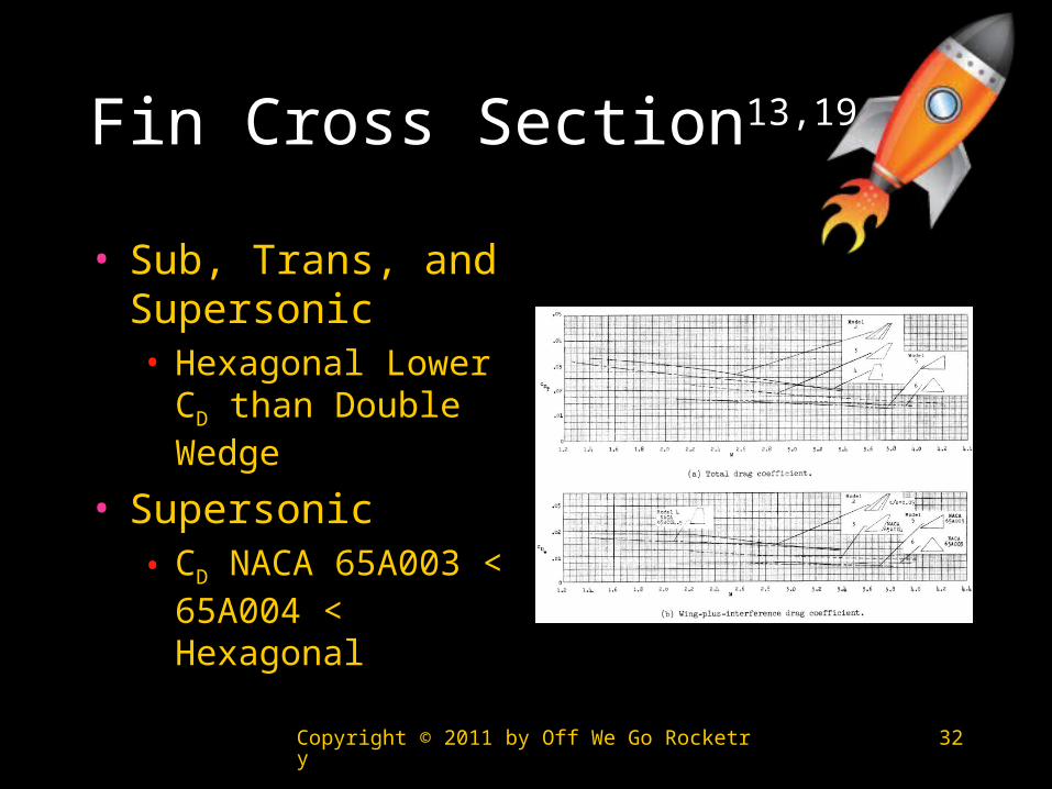
Fin Cross Section13,19
• Sub, Trans, and Supersonic• Hexagonal Lower
CD than Double Wedge
• Supersonic• CD NACA 65A003
< 65A004 < Hexagonal
Copyright © 2011 by Off We Go Rocketry 33
Shape14,19
• Supersonic Data• Trapezoidal (Clipped Delta) Lower CD
than Delta
• Delta and Diamond have Similar CD

Copyright © 2011 by Off We Go Rocketry 34
Multi-Disciplinary Design Optimization (MDO)x
• Optimizing Individual Components may not Result in an Optimum Design• Increasing Fin count from 3 to 4• Improving Nose Cone Fineness Ratio (3.5 vs. 7) may
Result in Increased Fin Drag at Some Velocities

Copyright © 2011 by Off We Go Rocketry 35
Summary
• Optimal Nose Cones• Subsonic – Elliptical• Transonic – Von Karman (Blunted 15% of Base Diameter)• Supersonic - X¾ Power Series• Hypersonic – X.6 Power Series• Fineness Ratio of 5
• Fin Optimization• Fin Count of 3• Fin Joints 4% to 8% of Root Cord• Thickness < 10% of Root Cord often between 3% & 6%• Trailing Edge Flat but < 0.7% of Root Cord in Thickness• Leading Edge may be Sharp• Sweep Angle between 45° and 70°• Flat Fin Tips• Hexagonal Cross Section• Clipped Delta Shape
Appendices
Nose Cones

Copyright © 2011 by Off We Go Rocketry 37
Nose Cone Geometries
• Conical• Elliptical• Ogive (Tangent)• Parabolic• Power Series• Sears-Haack (Von Karman)
Copyright © 2011 by Off We Go Rocketry 38
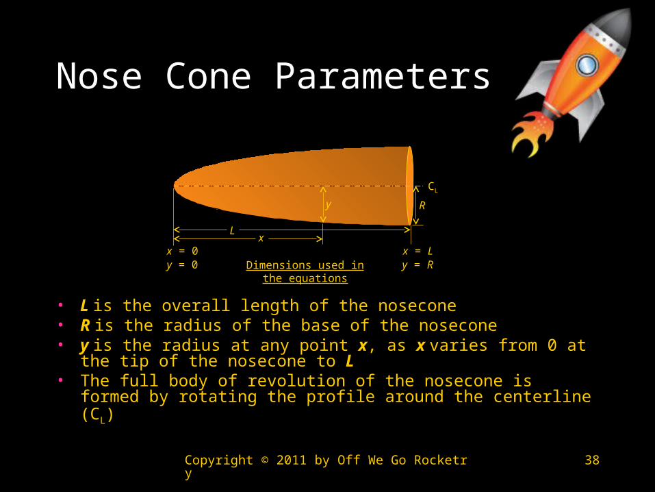
Nose Cone Parameters
• L is the overall length of the nosecone• R is the radius of the base of the nosecone• y is the radius at any point x, as x varies from 0 at the tip of
the nosecone to L• The full body of revolution of the nosecone is formed by
rotating the profile around the centerline (CL)
Dimensions used in the equations
L
R
x = 0 x = Lx
y
CL
y = Ry = 0
Copyright © 2011 by Off We Go Rocketry 39
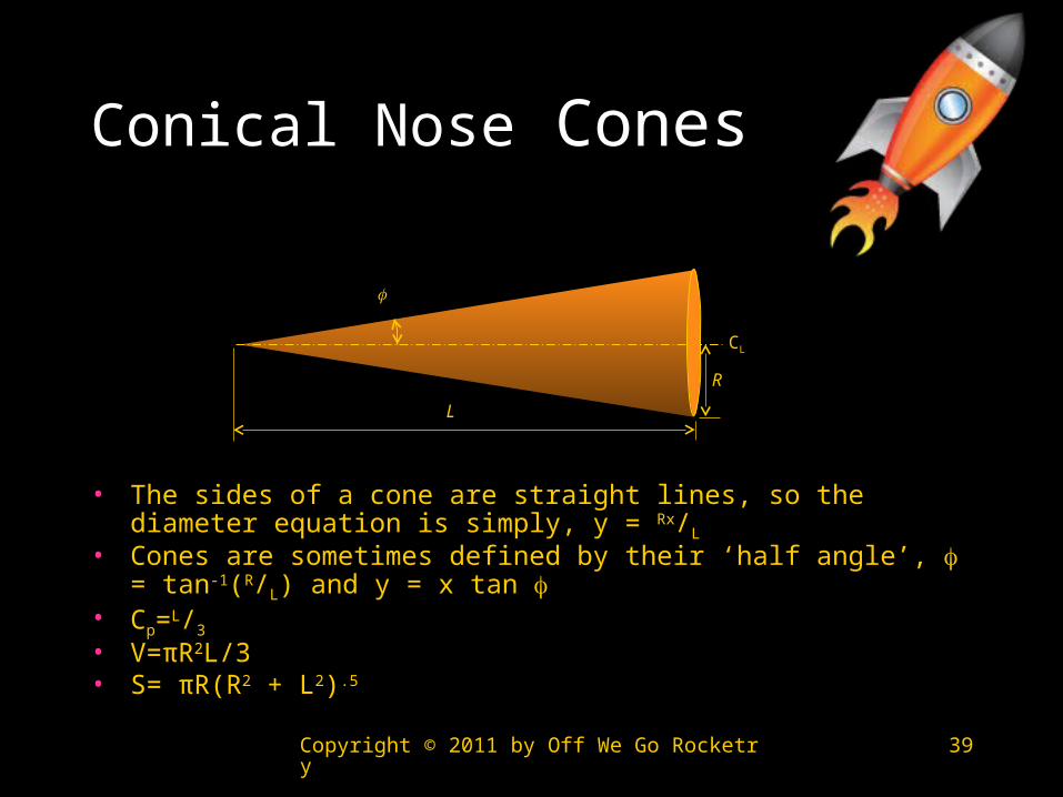
Conical Nose Cones
• The sides of a cone are straight lines, so the diameter equation is simply, y = Rx/L
• Cones are sometimes defined by their ‘half angle’, = tan-1(R/L) and y = x tan
• Cp=L/3
• V=πR2L/3• S= πR(R2 + L2).5
L
R
CL
yxR
LyxR
L

Copyright © 2011 by Off We Go Rocketry 40
Elliptical Nose Cones
• The profile of this shape is one-half of an ellipse, with the major axis being the centerline and the minor axis being the base of the nosecone
• This shape is advantageous for subsonic flight due to its blunt nose and tangent base
• It is defined by: y = R(1-x2/L2)½
• Cp=3L/2
• V=2πR2L/3• S=πL2+[πR2/σ[ln{(1+σ)/(1-σ)}]]/2 where σ=(L2+R2)/L
L
R
CL
Copyright © 2011 by Off We Go Rocketry 41
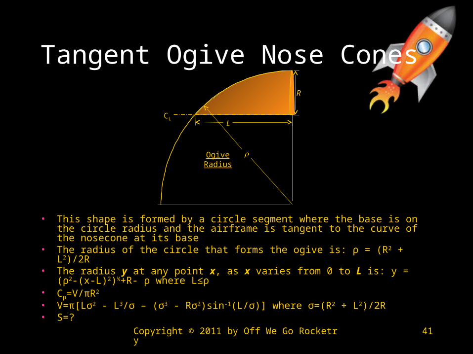
Tangent Ogive Nose Cones
• This shape is formed by a circle segment where the base is on the circle radius and the airframe is tangent to the curve of the nosecone at its base
• The radius of the circle that forms the ogive is: ρ = (R2 + L2)/2R• The radius y at any point x, as x varies from 0 to L is: y = (ρ2-(x-
L)2)½+R- ρ where L≤ρ• Cp=V/πR2
• V=π[Lσ2 - L3/σ – (σ3 - Rσ2)sin-1(L/σ)] where σ=(R2 + L2)/2R• S=?
L
R
Ogive Radius
CL
Copyright © 2011 by Off We Go Rocketry 42
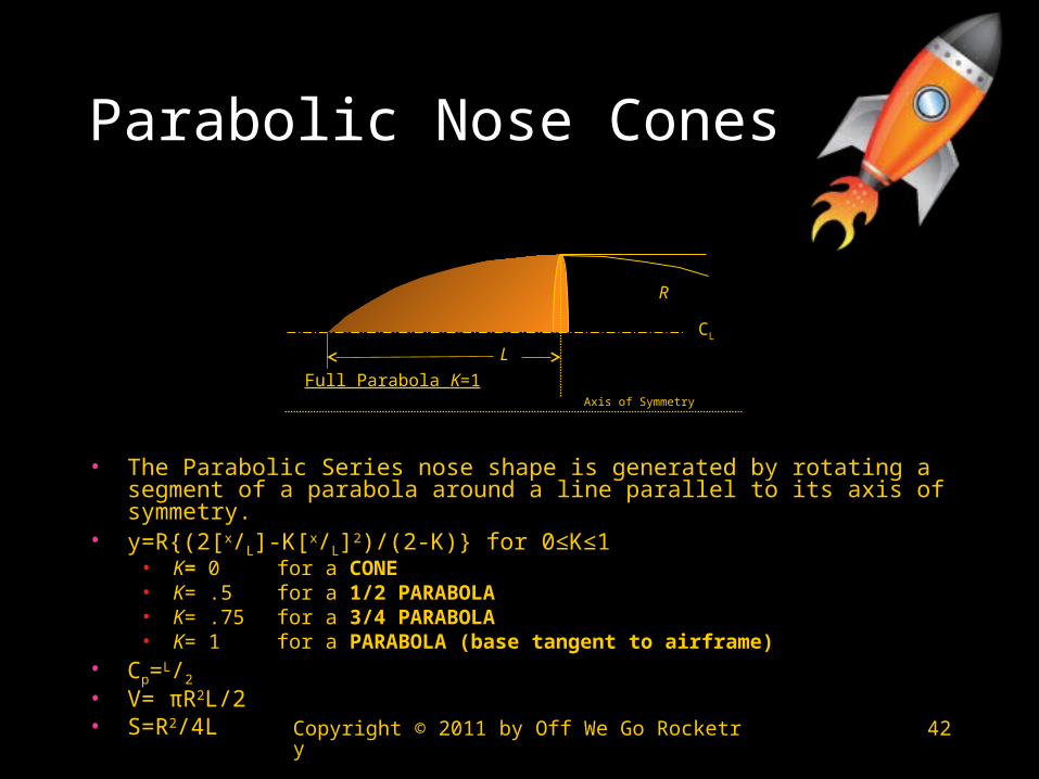
Parabolic Nose Cones
• The Parabolic Series nose shape is generated by rotating a segment of a parabola around a line parallel to its axis of symmetry.
• y=R{(2[x/L]-K[x/L]2)/(2-K)} for 0≤K≤1• K= 0 for a CONE• K= .5 for a 1/2 PARABOLA• K= .75 for a 3/4 PARABOLA• K= 1 for a PARABOLA (base tangent to airframe)
• Cp=L/2
• V= πR2L/2• S=R2/4L
R
L
CL
Full Parabola K=1Axis of Symmetry

Copyright © 2011 by Off We Go Rocketry 43
Power Series Nose Cones
• The Power Series shape is characterized by its (usually) blunt tip, and by the fact that its base is not tangent to the body tube.
• The Power series nose shape is generated by rotating a parabola about its major axis. The base of the nosecone is parallel to the latus rectum of the parabola, and the factor n controls the ‘bluntness’ of the shape. As n decreases towards zero, the Power Series nose shape becomes increasingly blunt; at values of n above about .7, the tip becomes sharp.
• y=R(x/L)n for 0≤n≤1• n = 1 for a CONE• n = .75 for a ¾ POWER• n = .5 for a ½ POWER (PARABOLA)• n = 0 for a CYLINDER
• Cp=?• V=?• S=?
L
R
Power Series
CL
Copyright © 2011 by Off We Go Rocketry 44
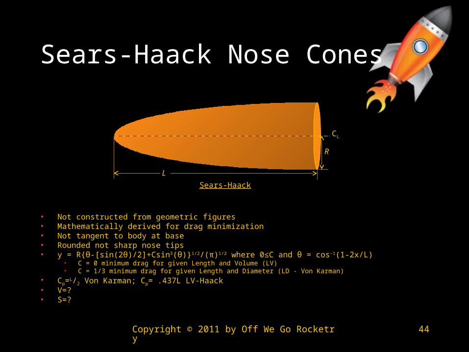
Sears-Haack Nose Cones
• Not constructed from geometric figures• Mathematically derived for drag minimization• Not tangent to body at base• Rounded not sharp nose tips• y = R{θ-[sin(2θ)/2]+Csin3(θ)}1/2/(π)1/2 where 0≤C and θ = cos-1(1-2x/L)
• C = 0 minimum drag for given Length and Volume (LV)• C = 1/3 minimum drag for given Length and Diameter (LD - Von Karman)
• Cp=L/2 Von Karman; Cp= .437L LV-Haack• V=?• S=?
L
R
Sears-Haack
CL

Copyright © 2011 by Off We Go Rocketry 45
Nose Cone References
1. Topics in Advanced Model Rocketry; Mandell, Gordon K.; Caporaso, George J.; Bengen, William P.; The MIT Press; 1973
2. Investigation of the Drag of Various Axially Symmetric Nose Shapes of Fineness Ratio 3 for Mach Numbers from 1.24 to 3.67; Perkins, Edward W.; Jorgensen, Leland H.; NACA Research Memorandum A52H28; 1952.
3. Investigation of the Drag of Various Axially Symmetric Nose Shapes of Fineness Ratio 3 for Mach Numbers from 1.24 to 7.4; Perkins, Edward W.; Jorgensen, Leland H.; Sommer, Simon C.; NACA Technical Report 1386; 1958.
4. Transonic Drag Measurements of Eight-Body Nose Shapes; Stoney, Jr., William, G.; NACA Research Memorandum L53K17; 1954.
5. The Effect of Bluntness on the Drag of Spherical-Tipped Truncated Cones of Fineness Ratio 3 at Mach Numbers 1.2 to 7.4; Sommer, Simon C.; Stark, James A.; NACA Research Memorandum A52B13; 1954.
6. Pressure Drag of Bodies at Mach Numbers up to 2.0; Nelson, Robert L.; Stoney, Jr., William, G.; NACA Research Memorandum L53I22c; 1953.
7. Bodies of Revolution having Minimum Drag at High Supersonic Airspeeds; Eggers Jr, A. J.; Resnikoff, Meyer M.; Dennis, David H.; NACA Technical Report 1306, 1957.
8. Hypersonic Aerodynamic Performance of Minimum-Wave-Drag Bodies; Spencer, Jr., Bernard; Fox Jr., Charles H.; NASA Technical Report R-250; 1966.
9. Longitudinal Aerodynamic Performance of a Series of Power-Law and Minimum-Wave-Drag Bodies at Mach 6 and Several Reynolds Numbers; Ashby Jr., George C.; NASA Technical Memorandum X-2713; 1974.
10. Performance and Dynamics of Aerospace Vehicles; Love, E. S.; NASA SP-258; 1971; pages 103-174.
Copyright © 2011 by Off We Go Rocketry 46
Fin References
11. Effect of Number of Fins on the Drag of a Pointed Body of Revolution at Low Supersonic Velocities; Mastrocola, N; NACA Research Memorandum L7A08; 1947.
12. Transonic Drag Characteristics of a Wing-Body Combination Showing the Effect of a Large Wing Fillet; Cheatham, Donald C.; Kurbjun, Max C.; NACA Research Memorandum L8F08; 1948.
13. Damping in Roll of Models with 45°, 60°, and 70° Delta Wings Determined at High Subsonic, Transonic, and Supersonic Speeds with Rocket-Powered Models; Saunders Jr, E Claude; NACA Research Memorandum L52D22a; 1952.
14. Aerodynamic Characteristics of Two Delta Wings and Two Trapezoidal Wings at Mach 4.04; Dunning, Robert W.; Smith, Fred W.; NACA Research Memorandum L53D30A; 1953.
15. Results of a Flight Investigation to Determine the Zero-Lift Drag Characteristics of a 60° Delta Wing with NACA 65-006 Airfoil Section and Various Double-Wedge Sections at Mach Numbers from 0.7 to 1.6; Welsh, Clement J.; NACA Technical Note 3650; 1956.
16. Summary of Flutter Experiences as a Guide to the Preliminary Design of Lifting Surfaces on Missiles; Martin, Dennis J.; NACA Technical Note 4197; 1958.
17. The Characteristics of 78 Related Airfoil Sections from Tests in the Variable-Density Wind Tunnel; Jacobs, Eastman N.; Ward, Kenneth E.; Pinkerton, Robert N; NACA Technical Report 460; 1948.
18. Tests of 16 Related Airfoils at High Speeds; Stack, John; Von Doenhoff, Albert E.; NACA Technical Report 492; 1935.
19. Free-Flight Measurements of the Zero-Lift Drag of Several Wings at Mach Numbers from 1.4 to 3.8; Jackson, H. Herbert; NASA Technical Note D-395; 1960.
20. Aeroelastic Optimization of Sounding Rocket Fins; Simmons III, Joseph R.; Air Force Institute of Technology; 2009.
21. NASA Supercritical Airfoils; Harris, Charles D.; NASA Technical Paper 2969; 1990.

Copyright © 2011 by Off We Go Rocketry 47
MDO References
1. Results of Flight Tests at Supersonic Speeds to Determine the Effect of Body Nose Fineness Ratio on Body and Wing Drag; Katz, Ellis R; NACA Research Memorandum L7B19; 1947.

Copyright © 2011 by Off We Go Rocketry 48
Selected Websites
• http://exploration.grc.nasa.gov/education/rocket/guided.htm
• http://ntrs.nasa.gov/search.jsp• http://www.apogeerockets.com/
Peak-of-Flight_index.asp• http://www.rocketmaterials.org/• http://www.aerorocket.com/