Embed Size (px)
Citation preview

North Mountain IMS Medical
Office Building
Phoenix, Arizona
Michael Hopple
Technical Assignment 1
October 5th, 2007
AE 481W-Senior Thesis
The Pennsylvania State University
Faculty Adviser: Dr. Ali Memari, P.E.
[Hopple‐Tech Assignment 1] Page 2
Table Of Contents
Executive Summary Page 3
Codes and Standards Page 4
Typical Framing Plans and Details Page 5 Load Summary Page 8 Evaluation of Structural System Page 10 Double Tee Spot-check Page 11
Appendix Page 12 Structure Weight Calculation Page 12 Seismic Base Shear Calculation Page 16 Seismic Load Distribution Page 18 Wind Load Calculation Page 19 Double Tee Spot-check Calculation Page 22

Executive Summary
Technical Assignment 1 is an existing conditions report of North Mountain IMS Medical Office Building. This report will explore the basic structural concepts that led to the design of this complete precast concrete building. Framing plans and lateral load-resisting systems are analyzed to better understand the design concepts of the overall structure. Calculations of seismic and wind loading are included in the Appendix.
North Mountain IMS Office Building is a 123,400 square feet precast concrete office building located in Phoenix, Arizona. This $10 million design-build project started construction in June of 2007 and is expected to be completed February 2008. It features a state-of-the-art outpatient diagnostic imaging center and ambulatory surgery center on the ground floor. The remaining floors feature over 92,000 square feet of open, rentable office space. The total building height is 60 feet, with a mechanical parapet wall that reaches 70 feet above ground level.
North Mountain’s structural system consists exclusively of precast concrete products. Precast, pre-stressed concrete double tees provide the floor and roof. These double tees bear on exterior walls and interior pre-stressed inverted tee girders. The girders then bear on columns which carry gravity load down to the foundation. The columns are attached to circular concrete caissons, which are drilled to a max depth of 30 feet. The lateral load resisting system consists entirely of concrete shear walls.
A flexural spot-check calculation for a typical 48’ span double tee was conducted to check the size of the double tee. A lateral analysis was also completed. Due to the weight of the structure and the higher seismic loads in the Phoenix region, earthquake loads exceed those of wind loads. Calculations of the spot-check and lateral loads are located in the Appendix.
[Hopple‐Tech Assignment 1] Page 3

[Hopple‐Tech Assignment 1] Page 4
Codes and Standards Note: The Senior Thesis project requires the use of the most current codes and standards, those referenced for calculations in this report are listed at the end of this section. Building Codes: 1. International Building Code (IBC), 2003 edition 2. International Energy Code (IECC), 2003 edition with 2004 supplements 3. National Electric Code (NEC), 2005 edition with Phoenix amendments
4. International Mechanical Code (IMC), 2003 edition with Phoenix amendments 5. Arizona State Plumbing Code, with 2003 supplements 6. Uniform Fire Code (UFC), 1997 edition with Phoenix amendments
Structural Codes:
1. American Concrete Institute (ACI-318), 2002 edition 2. Precast Concrete Institute (PCI), 6th edition
Building Design Loads:
1. American Society of Civil Engineers (ASCE-7), 2002 edition
Thesis Project Codes and Loads: 1. IBC 2005 2. ASCE-7, 2005 3. PCI, 6th edition

Typical Framing Plans and Details North Mountain IMS Office Building floor framing consists of 24” deep, 10’ wide double tees with a minimum of 3-1/4” concrete topping. The tees are normal-weight concrete and have a 28-day compressive strength of 6,000 psi. The minimum prestress release strength is 4,200 psi. The prestressing strand is 7 wire, ½” diameter 270 ksi low relaxation strand. Each strand is pulled to 72.5% capacity, which results in a 30 kip force. The strand is held down at one point in the middle of the tee. Depressed strand provides greater flexural strength while reducing the stresses in the concrete during prestress release. Typical spans are 44’, 48’, and 54’. A typical floor plan is shown below.
[Hopple‐Tech Assignment 1] Page 5

The 24” deep double tees bear on 24” deep by 32” wide inverted tee girders. 28-day strength is 7,500 psi and minimum release strength is 3,750 psi. Typical inverted tee girders use 22 ½” diameter stand for tensile reinforcement. Span length for a 30’ bay is 28’ due to the columns on each end. Dapped ends on the double tees allow the top of the tee to line flush with the top of the girder. The topping is then poured over the tee and the girder at the same time, interlocking them. This construction technique is known as emulation. Emulation design creates construction that is either monolithic at critical joints, or provides connections that act as if they are monolithic at those locations. This is a great way to connect precast pieces in high seismic zones. Interior spans of inverted tee girders bear on 24” x 24” columns. Concrete strength is 6,000 psi. There is no need for prestressing strand in columns, because there is no large tensile zone. Any tension in the columns is addressed with traditional reinforcing bars. These columns are 56’ tall and arrive on site in one piece. These columns are a great showcase of precast concrete’s advantages over other structural systems. The columns only need one connection, to the foundation. This ease of construction makes North Mountain’s erection duration much shorter compared to other systems. However, long lead times may be an issue due to cure time and storage at the precast fabrication plant. A typical interior elevation is shown below to demonstrate the bearing conditions for inverted tee girders and columns.
The exterior walls for North Mountain IMS Office Building fulfill many different structural requirements. First, and most importantly, they provide the building enclosure. Second, they support gravity load from double tees. Third, the walls are detailed to provide a pleasant architectural aesthetic. Last, but also extremely important, they resist the lateral forces due to wind and earthquakes. These walls give the structure its rigidity and structural integrity. Without shear walls, a moment-resisting frame system would have to be used. This structure utilizes interior and exterior shear walls. The interior shear walls are located in the center of the building around the elevator shaft and a stair tower.
[Hopple‐Tech Assignment 1] Page 6

Below is an exterior elevation. It is easy to notice the different textures applied to the exterior of these walls. These finishes are applied when the panels are cast, which makes for no further work when they arrive on site. Also, the exterior wall sections showcase the bearing condition for double tees.
[Hopple‐Tech Assignment 1] Page 7

[Hopple‐Tech Assignment 1] Page 8
Load Summary Live Loads:
• Roof Live Load………………………………………………..20 psf • Floor Live Load……………………………………………….80 psf • Stair Live Load………………………………………………100 psf • Partition Live Load……………………………………………20 psf
Dead Loads:
• Superimposed Roof Dead Load……………………………….15 psf • Superimposed Floor Dead Load………………………………15 psf
Wind Load:
• Total Wind Force (North-South Direction)…………………218 kips • Total Wind Force (East-West Direction)……………...…….285 kips
Seismic Load:
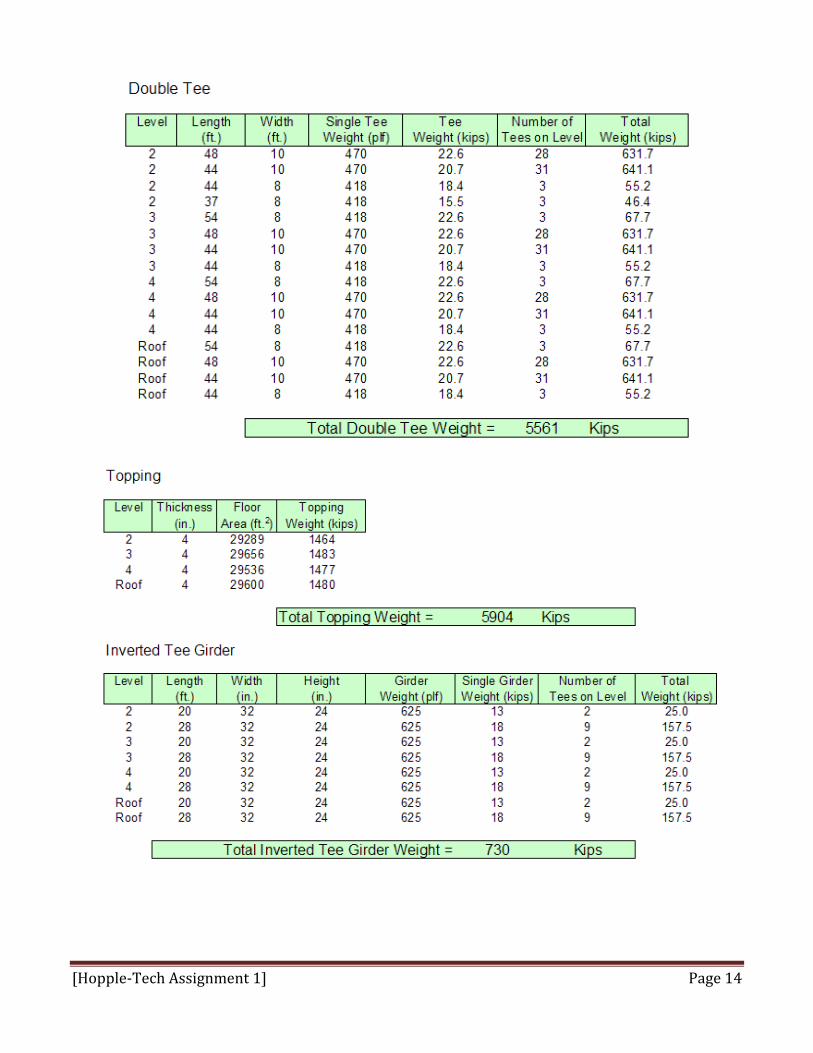
• Design Base Shear…………………..……………………..1627 kips The floor live loads for North Mountain are typical office loads. The second, third, and forth floors all feature an open floor plan with no set dimensions for walls or corridors. Because of the open floor plan, the floor live load is 80 psf. By code, corridor loading above the first floor is 80 psf. This value was used as the live load over the entire floor. In design, it is much easier to assume a uniform load over the entire floor compared to breaking the loads down between office and corridors. Also, a partition live load of 20 psf is used over the entire floor. The floor dead load only accounts for 15 psf of superimposed load which includes mechanical, electrical, and pluming equipment. The nature of precast concrete structures makes it very simple to calculate the actual weight of the structure; a dead load in pounds per square foot is not needed because each piece of precast is detailed and the exact weight calculated. Tabulated structure weights can be found on pages 12-15 in the Appendix. Wind load was not expected to control the lateral design due to the overall dimensions of North Mountain. The building is fairly short and it is not located in a high wind zone. Also, there are no abnormal site features, such as hills or valleys, which would increase the wind speed. The complete wind load calculation is provided in the Appendix on pages 19-21. For this report, Method 2 from ASCE-7 2005 was used to calculate wind pressures on the main wind-force resisting system. The resulting calculations gave a base shear value of 218 kips in the North-South direction and 285 kips in the East-West direction. Seismic loading was expected to control the lateral design, and this turned out to be the case. The design base shear for North Mountain is actually over five times higher than the shear load due to wind. The precast structure is very heavy, which is the main cause for such a high seismic load. A significant component of that weight is the topping for the double tees. The precast double tees have a 2” flange with a minimum topping of 3-1/4”. I used a topping dimension of 4” for each floor and the roof, giving a total slab depth of 6”. Also, the exterior walls are concrete which is much heavier than

[Hopple‐Tech Assignment 1] Page 9
typical curtain wall systems. The calculated design base shear is 1627 kips, which is very similar to the value the design professional used. All concrete on the project is normal-weight. Using light-weight concrete would considerably reduce the earthquake load on the building. Complete seismic calculations can be found on pages 16-18 in the Appendix.
[Hopple‐Tech Assignment 1] Page 10
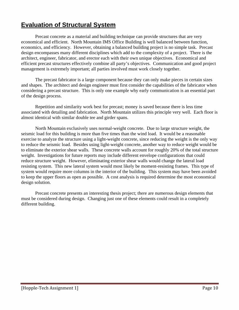
Evaluation of Structural System Precast concrete as a material and building technique can provide structures that are very economical and efficient. North Mountain IMS Office Building is well balanced between function, economics, and efficiency. However, obtaining a balanced building project is no simple task. Precast design encompasses many different disciplines which add to the complexity of a project. There is the architect, engineer, fabricator, and erector each with their own unique objectives. Economical and efficient precast structures effectively combine all party’s objectives. Communication and good project management is extremely important; all parties involved must work closely together. The precast fabricator is a large component because they can only make pieces in certain sizes and shapes. The architect and design engineer must first consider the capabilities of the fabricator when considering a precast structure. This is only one example why early communication is an essential part of the design process. Repetition and similarity work best for precast; money is saved because there is less time associated with detailing and fabrication. North Mountain utilizes this principle very well. Each floor is almost identical with similar double tee and girder spans. North Mountain exclusively uses normal-weight concrete. Due to large structure weight, the seismic load for this building is more than five times than the wind load. It would be a reasonable exercise to analyze the structure using a light-weight concrete, since reducing the weight is the only way to reduce the seismic load. Besides using light-weight concrete, another way to reduce weight would be to eliminate the exterior shear walls. These concrete walls account for roughly 20% of the total structure weight. Investigations for future reports may include different envelope configurations that could reduce structure weight. However, eliminating exterior shear walls would change the lateral load resisting system. This new lateral system would most likely be moment-resisting frames. This type of system would require more columns in the interior of the building. This system may have been avoided to keep the upper floors as open as possible. A cost analysis is required determine the most economical design solution. Precast concrete presents an interesting thesis project; there are numerous design elements that must be considered during design. Changing just one of these elements could result in a completely different building.

[Hopple‐Tech Assignment 1] Page 11
Double Tee Spot-check To spot check a 48’ span double tee, the PCI Design Handbook 6th edition was used. The calculation checks the concrete stresses at release and at service loads in flexure only. Other design requirements for double tees include transverse bending of the flange shear capacity. These requirements, although important for structural performance, are beyond the scope of this report. Such requirements are based on the fabricator’s standards and are more a detailing issue than a engineering issue. Refer to pages 22-24 in the Appendix for calculations. Upon review of the calculations, two areas of concern arose. At release, the compressive stress in the bottom fibers is higher than code limits. Since the stress is over by less than 5%, this error could be accounted for in the estimated section properties. Section properties used by the design professional were unavailable for the hand calculation. Also, the tensile stress at 0.4L under service load was calculated much higher than allowable by code. This could be the result of using a span greater than the actual span. A span of 48’ does not account for the ledges on the inverted tee girder or the thickness of the girder itself. A more accurate span of the double tee is 47’. Once again, a difference in section properties may have had role in the discrepancies in stresses.

Appendix Structure Weight Calculation
[Hopple‐Tech Assignment 1] Page 12

[Hopple‐Tech Assignment 1] Page 13
[Hopple‐Tech Assignment 1] Page 14

[Hopple‐Tech Assignment 1] Page 15

Seismic Base Shear Calculation
[Hopple‐Tech Assignment 1] Page 16

[Hopple‐Tech Assignment 1] Page 17

Seismic Load Distribution
[Hopple‐Tech Assignment 1] Page 18

Wind Load Calculation
[Hopple‐Tech Assignment 1] Page 19

[Hopple‐Tech Assignment 1] Page 20

[Hopple‐Tech Assignment 1] Page 21

Double Tee Spot-check Calculation
[Hopple‐Tech Assignment 1] Page 22

[Hopple‐Tech Assignment 1] Page 23

[Hopple‐Tech Assignment 1] Page 24