Embed Size (px)
Citation preview

PROPOSED ACTION
North Fork Mancos Master Development Plan
for
Oil and Gas Exploration and Development
Gunnison and Delta Counties, Colorado
DOI-BLM-CO-N040-2017-050-EA
Prepared by
Gunnison Energy LLC
1801 Broadway, Suite 1200
Denver, Colorado 80202
Phone: 303-296-4222
Fax: 303-496-4555
Prepared for
Bureau of Land Management
Colorado River Valley Field Office
2300 River Frontage Road
Silt, Colorado 81652
Phone: 970-876-9000
Fax: 970-876-9090
January 2017

Left blank for two-sided copying.

Gunnison Energy LLC
Proposed Action, North Fork Mancos MDP
DOI-BLM-CO-N040-2017-050-EA
i
Table of Contents
1.0 INTRODUCTION ................................................................................................................................ 1 2.0 PROJECT LOCATION AND ACCESS .............................................................................................. 5 3.0 EXISTING AND APPROVED DEVELOPMENT AND INFRASTRUCTURE ............................... 5
3.1 EXISTING DEVELOPMENT AND INFRASTRUCTURE ........................................................................... 7 3.2 APPROVED DEVELOPMENT AND INFRASTRUCTURE – NOT CONSTRUCTED ..................................... 7
4.0 PROJECT COMPONENTS ................................................................................................................. 7 4.1 CONSTRUCTION .............................................................................................................................. 21 4.2 OPERATIONS ................................................................................................................................... 26 4.3 WATER SUPPLY, USE, AND DISPOSAL ........................................................................................... 27 4.4 WASTE HANDLING ......................................................................................................................... 29 4.5 SAFETY ........................................................................................................................................... 30 4.6 SCHEDULE ...................................................................................................................................... 31 4.7 WORKFORCE .................................................................................................................................. 31 4.8 TRAFFIC.......................................................................................................................................... 32 4.9 RECLAMATION ............................................................................................................................... 34 4.10 REPRESENTATIVE APPLICANT-COMMITTED MEASURES ............................................................... 37
Tables
Table 1. GELLC Existing and Approved Development .............................................................................. 6 Table 2. Proposed Disturbance for Project Components ............................................................................. 8 Table 3. Proposed Well Pads by Lease and Surface and Mineral Ownership ........................................... 20 Table 4. Estimated Annual Water Usage during Construction, Drilling, and Completion ........................ 28 Table 5. Estimated Workforce for a Single Well ....................................................................................... 32 Table 6. Estimated Vehicle Round-Trips per Activity for Construction of a Single Well ........................ 33
Maps
Map 1 General Location ............................................................................................................................... 2 Map 2 Proposed Action ................................................................................................................................ 3 Map 3 Proposed Action and Previously Approved GELLC Well Pads ....................................................... 4 Map 4 Detailed Location of Proposed Federal 1090 #30 Well Pad ............................................................ 10 Map 5 Detailed Location of Proposed Federal 1190 #20 Well Pad ............................................................ 12 Map 6 Detailed Location of Proposed Federal 1190 #29 Well Pad ............................................................ 14 Map 7 Detailed Location of Proposed DGU 1289 #20-23 Well Pad .......................................................... 16 Map 8 Detailed Location of Existing IPU 1291 #13-24 Well Pad ............................................................ 18
Figures
Figure 1 Preliminary Layout for Federal 1090 #30 Well Pad ..................................................................... 11
Figure 2 Preliminary Layout for Federal 1190 #20 Well Pad ..................................................................... 13
Figure 3 Preliminary Layout for Federal 1190 #29 Well Pad ..................................................................... 15
Figure 4 Preliminary Layout for DGU 1289 #20-23 Well Pad ................................................................... 17
Figure 5 Preliminary Layout for Existing IPU 1291 #13-24 Well Pad ....................................................... 19

Left blank for two-sided copying.
Gunnison Energy, LLC
Proposed Action, North Fork Mancos MDP
DOI-BLM-CO-N040-2017-0050-EA
1
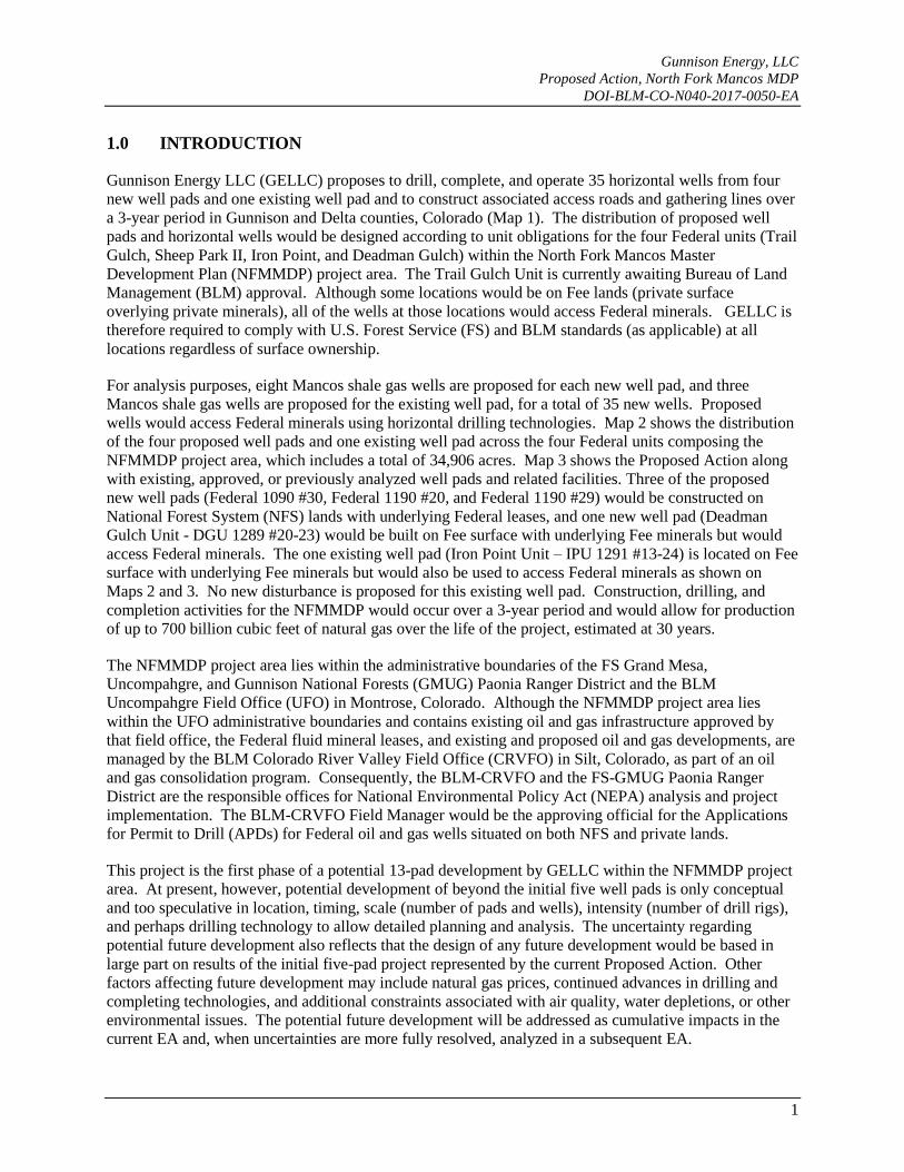
1.0 INTRODUCTION
Gunnison Energy LLC (GELLC) proposes to drill, complete, and operate 35 horizontal wells from four
new well pads and one existing well pad and to construct associated access roads and gathering lines over
a 3-year period in Gunnison and Delta counties, Colorado (Map 1). The distribution of proposed well
pads and horizontal wells would be designed according to unit obligations for the four Federal units (Trail
Gulch, Sheep Park II, Iron Point, and Deadman Gulch) within the North Fork Mancos Master
Development Plan (NFMMDP) project area. The Trail Gulch Unit is currently awaiting Bureau of Land
Management (BLM) approval. Although some locations would be on Fee lands (private surface
overlying private minerals), all of the wells at those locations would access Federal minerals. GELLC is
therefore required to comply with U.S. Forest Service (FS) and BLM standards (as applicable) at all
locations regardless of surface ownership.
For analysis purposes, eight Mancos shale gas wells are proposed for each new well pad, and three
Mancos shale gas wells are proposed for the existing well pad, for a total of 35 new wells. Proposed
wells would access Federal minerals using horizontal drilling technologies. Map 2 shows the distribution
of the four proposed well pads and one existing well pad across the four Federal units composing the
NFMMDP project area, which includes a total of 34,906 acres. Map 3 shows the Proposed Action along
with existing, approved, or previously analyzed well pads and related facilities. Three of the proposed
new well pads (Federal 1090 #30, Federal 1190 #20, and Federal 1190 #29) would be constructed on
National Forest System (NFS) lands with underlying Federal leases, and one new well pad (Deadman
Gulch Unit - DGU 1289 #20-23) would be built on Fee surface with underlying Fee minerals but would
access Federal minerals. The one existing well pad (Iron Point Unit – IPU 1291 #13-24) is located on Fee
surface with underlying Fee minerals but would also be used to access Federal minerals as shown on
Maps 2 and 3. No new disturbance is proposed for this existing well pad. Construction, drilling, and
completion activities for the NFMMDP would occur over a 3-year period and would allow for production
of up to 700 billion cubic feet of natural gas over the life of the project, estimated at 30 years.
The NFMMDP project area lies within the administrative boundaries of the FS Grand Mesa,
Uncompahgre, and Gunnison National Forests (GMUG) Paonia Ranger District and the BLM
Uncompahgre Field Office (UFO) in Montrose, Colorado. Although the NFMMDP project area lies
within the UFO administrative boundaries and contains existing oil and gas infrastructure approved by
that field office, the Federal fluid mineral leases, and existing and proposed oil and gas developments, are
managed by the BLM Colorado River Valley Field Office (CRVFO) in Silt, Colorado, as part of an oil
and gas consolidation program. Consequently, the BLM-CRVFO and the FS-GMUG Paonia Ranger
District are the responsible offices for National Environmental Policy Act (NEPA) analysis and project
implementation. The BLM-CRVFO Field Manager would be the approving official for the Applications
for Permit to Drill (APDs) for Federal oil and gas wells situated on both NFS and private lands.
This project is the first phase of a potential 13-pad development by GELLC within the NFMMDP project
area. At present, however, potential development of beyond the initial five well pads is only conceptual
and too speculative in location, timing, scale (number of pads and wells), intensity (number of drill rigs),
and perhaps drilling technology to allow detailed planning and analysis. The uncertainty regarding
potential future development also reflects that the design of any future development would be based in
large part on results of the initial five-pad project represented by the current Proposed Action. Other
factors affecting future development may include natural gas prices, continued advances in drilling and
completing technologies, and additional constraints associated with air quality, water depletions, or other
environmental issues. The potential future development will be addressed as cumulative impacts in the
current EA and, when uncertainties are more fully resolved, analyzed in a subsequent EA.

Federal 1090 #30
IPU 1291 #13-24 DGU 1289 #20-23
Federal 1190 #20
Federal 1190 #29#*
Somerset
McClure Pass
UV265
CrawfordReservoir
Rifle GapReservoir
RuediReservoir
VegaReservoir
GunnisonGorge National
Conservation AreaGunnison
GorgeWilderness
Gunnison GorgeWildernessStudy Area
White RiverNationalForest
GunnisonNationalForest
CollegiatePeaks
Wilderness
MaroonBells-Snowmass
Wilderness
RaggedsWilderness
WestElk
Wilderness
PaoniaReservoir
Grand MesaNationalForest
NavalOil ShaleReserve
UV347
UV348
UV13
UV92 UV135
UV82
UV65
UV330UV133
£¤6
£¤50
§̈¦70
Cedaredge
Delta
Orchard City Paonia
Basalt
Eagle
El Jebel
Gypsum
BattlementMesa
Carbondale
GlenwoodSprings
New Castle
Rifle
Silt
Crested Butte
Olathe
Aspen
SnowmassVillage
Delta County
GunnisonCounty
Mesa County
MontroseCounty
Eagle County
GarfieldCounty
Pitkin County
10 0 105Miles MAP 1
General Location
North Fork Mancos Master Development Plan
tProject
Title
Scale As ShownFile No.
Rev 0
01/10/1701/10/1701/10/17
Review:Check:GIS:Project No. 014-02
MABMABJST
Path:
M:\G
unnis
on_E
nergy
\Mud
dyBa
sin\Ar
cMap
\Nort
h Fork
Man
cos\P
ropos
al\Ma
p 1 - G
enera
l Loc
ation
.mxd
Deadman Gulch Federal UnitIron Point Federal UnitSheep Park II Federal UnitTrail Gulch Federal UnitNFMMDP Project Area
Forest ServiceDepartment of DefenseBureau of Land ManagementNational Park ServiceBureau of Reclaimation
ColoradoUTKS
NEWY
NM OKAZ
§̈¦76
§̈¦70
§̈¦25
2

SheepGathering System
T 10 ST 11 S
T 11 ST 12 S
R 91
WR
90 W
R 90
WR
89 W
Option 2 AccessOption 1 Access
Delta
Gunn
ison
Hubbard CanyonRd
Clear Fork Rd
UV133
UV133
503.1
851
704
844
265
IPU 1291#13-24
DGU 1289#20-23
Federal1090 #30
Federal1190 #20
Federal1190 #29
36 3136 36 3131
611 616
313631
363136
611 616
36 31313631 362 0 21Miles
MAP 2
Proposed Action
North Fork Mancos Master Development Plan
tProject
Title
Scale As ShownFile No.
Rev 0
01/10/1701/10/1701/10/17
Review:Check:GIS:Project No. 014-02
MABMABJST
Path:
M:\G
unnis
on_E
nergy
\Mud
dyBa
sin\Ar
cMap
\Nort
h Fork
Man
cos\P
ropos
al\Ma
p 2 - P
ropos
ed Ac
tion.m
xd
Access RoadsExistingExisting - To Be UpgradedTo Be Constructed
Pipelines / Gathering LinesBull MountainExistingProposedNFMMDP Project Area
Existing Well PadProposed Well PadDeadman Gulch Federal UnitIron Point Federal UnitSheep Park II Federal UnitTrail Gulch Federal UnitBureau of Land ManagementU.S. Forest ServicePrivateBLM Field Office Boundary
3

£¤133
UV265
UV851
£¤133
T 10 ST 11 S
T 11 ST 12 S
R 91
WR
90 W
R 90
WR
89 W
Jacobs1290 #6-32
Allen1291 #12-13
IPU1291 #13-24
Sheep-BullConnector Pipeline
Option 2 AccessOption 1 Access
Federal 16-4
Federal 21-7
Federal1090 #33Federal
1090 #31
HotchkissFederal18-43
HotchkissFederal17-13
HotchkissFederal17-11
HotchkissFederal18-31
HotchkissFederal20-12
HotchkissFederal18-22D
Federal1190 #7
Allen12-24
HotchkissSec 18 Pad
Henderson8-14
Spadafora20-21
Lone Pine #1A
Hotchkiss1290 #1-34
849.1B1
849.0
851.0
844.0
503.1
844.1A
265.0
265.070
4.0
265.070
4.0
DGU 1289#20-23
Federal1090 #30
Federal1190 #20
Federal1190 #29
36 3136 36 3131
611
6
1
6
313631 36
3136
611 616
36 31313631 36
2 0 21Miles MAP 3
Proposed Action andPreviously Approved GELLC Projects
North Fork Mancos Master Development Plan
tProject
Title
Scale As ShownFile No.
Rev 0
01/10/1701/10/1701/10/17
Review:Check:GIS:Project No. 014-02
MABMABJST
Path:
M:\G
unnis
on_E
nergy
\Mud
dyBa
sin\Ar
cMap
\Nort
h Fork
Man
cos\P
ropos
al\Ma
p 3 - P
ropos
ed Ac
tion a
nd P
reviou
sly Ap
prove
d.mxd
Access RoadsExistingExisting - To Be UpgradedTo Be Constructed
Pipelines / Gathering LinesBull MountainExistingProposedNFMMDP Project Area
Proposed New Well PadApproved Well PadExisting Well PadDeadman Gulch Federal UnitIron Point Federal UnitSheep Park II Federal UnitTrail Gulch Federal UnitBLM Field Office Boundary
4

Gunnison Energy LLC
Proposed Action, North Fork Mancos MDP
DOI-BLM-CO-N040-2017-050-EA
5
2.0 PROJECT LOCATION AND ACCESS
The NFMMDP Federal units are located in the northwestern corner of Gunnison County and on the
eastern edge of Delta County in the North Fork of the Gunnison River Basin of west central Colorado
(Map 1). The NFMMDP project area is located approximately 10 miles northeast of Paonia, Colorado,
and approximately 20 miles southwest of Carbondale, Colorado.
Legal descriptions for the NFMMDP project area are as follows:
6th Principal Meridian, Mesa County, Colorado
T. 10 S., R. 90 W., All of Sections 16-21, 28-33
T. 11 S., R. 90 W., All or parts of Sections 3-10, 16-22, and 27-31
T. 12 S., R. 89 W., All or parts of Sections 17-20
T. 12 S., R. 90 W., All or parts of Sections 3-11, 1314, 18-19, 24, and 30
T. 12 S., R. 91 W., Parts of Sections 11-14, 23-26
Proposed well pad locations and surface ownership are shown on Map 2. Surface ownership within the
34,906 acre NFMMDP project area is NFS lands (25,790), BLM-administered lands (468 acres), and
private lands (8,648 acres). The NFMMDP project area includes 46 Federal leases totaling 30,972 acres
of which 4,714 acres are “split estate” (private surface with underlying Federal minerals). The status of
each Federal unit is described below:
Trail Gulch Unit – Received designation on 10/18/2016; currently awaiting BLM approval. After
final BLM approval is granted, GELLC would have 6 months to drill the unit obligation well.
Sheep Park II Unit – Approved by the BLM on 4/30/2015. The unit and the leases are currently
in suspense until drilling of the unit obligation well can be resumed in spring 2017.
Iron Point Unit – Effective date of the unit is 8/9/2014. A participating area has been established.
The unit will enter the continuous drilling phase on 8/9/2019.
Deadman Gulch Unit – Effective date of the unit is 9/15/2012. A participating area has been
established. The unit will enter the continuous drilling phase on 9/15/2017.
Colorado State Highway 133 (SH 133) is the main access to the NFMMDP project area (Map 2). From
the Town of Carbondale, access to the NFMMDP project area follows SH 133 south for 25 miles to
McClure Pass and then another approximately 10 miles from McClure Pass to County Road (CR) 265.
CR 265 is followed for approximately 5 miles to the NFMMDP project area boundary. Inside the
NFMMDP project area, unpaved NFS and County Roads, and private roads, would be used to access the
individual well pads.
3.0 EXISTING AND APPROVED DEVELOPMENT AND INFRASTRUCTURE
Table 1 provides a listing of existing or approved GELLC wells pads, wells, and associated infrastructure
in the NFMMDP project area (also see Map 3). The general project vicinity shown on Map 2 and Map 3,
but outside the NFMMDP project boundary, includes existing or approved wells and other infrastructure
with various operators. The BLM is currently awaiting publication of the Final Record of Decision
(ROD) for the Bull Mountain Unit MDP/EIS (Environmental Impact Statement), which proposes
development of Federal and private fluid minerals from private lands immediately east of the NFMMDP
project area.

Gunnison Energy LLC
Proposed Action, North Fork Mancos MDP
DOI-BLM-CO-N040-2017-050-EA
6
Table 1. GELLC Existing and Approved Development
Project Component Unit Year Constructed and Status 1 NEPA Approval
Federal 1090-31
Trail Gulch
1977 – one producing gas well
Approved by FS
Federal 1090 #33 1977 – one producing gas well
Federal 16-4 1981 – one producing gas well
Federal 1090 #30-4 1981– one producing gas well
Federal 1090-32 1983 – one producing gas well
Federal 21-7 1993 – one shut-in gas
Federal 1190 #17
Sheep Park II
1976 – one shut-in gas well Approved by FS
Federal 1190 #7 1977 – one plugged and abandoned
gas well Unknown
Jacobs 1290 #6-32 2007 – one shut-in coal seam well No NEPA (Private)
Spadafora #20-21 2016 – two approved gas wells CO-S050-2015-0029-EA
Henderson #8-14 2016 – one approved gas well
Lone Pine #1A
Iron Point
2004 – one shut-in coal seam well
No NEPA (Private)
Allen #12-24 2005 – one producing coal seam well
Allen 1291 #12-13 2007 – one shut-in water disposal
well
IPU 1291 #13-24 2011 – one producing shale well, one
shut-in coal seam well
Hotchkiss Federal 17-13
Deadman Gulch
2005 – one producing coal seam
well, one APD pending drilling CO-150-2005-45-EA
DGU Federal 1289 #18-
43
2006 – one producing coal seam
well, two APDs pending drilling CO-150-2006-022-EA
Hotchkiss Federal 20-12 2006 – one producing shale well
Hotchkiss 1290 #1-34 2006 – one producing coal seam well No NEPA (Private)
Hotchkiss Federal 18-31 2006 – one producing coal seam well CO-150-2006-022-EA
Hotchkiss 1289 #18-22D 2006 – one active water disposal well
Hotchkiss Federal 17-11 2009 – one producing shale well, two
APDs pending drilling CO-150-2008-35-EA
Hotchkiss #18 Pad
2014 – two producing shale wells;
two coal seam wells awaiting
completion
DOI-BLM-CO-S050-2014-
009 CX (390)
Hotchkiss Water Storage
Facility 2010 – Active No NEPA (Private)
Sheep Gas Gathering line
(also water line) Various Constructed 2008 and 2009
EA, Paonia Ranger District,
June 2007
Sheep-Bull Connector Non-Unit Approved – not constructed CX – Forest Service,
October 2010
1 Includes gas wells (conventional wells), coal seam wells, and marine shale wells.

Gunnison Energy LLC
Proposed Action, North Fork Mancos MDP
DOI-BLM-CO-N040-2017-050-EA
7
3.1 EXISTING DEVELOPMENT AND INFRASTRUCTURE
Currently, GELLC operates 21 well pads within or adjacent to the NFMMDP project area (Map 3).
These include six in the Trail Gulch Unit, three in the Sheep Park II Unit, four in the Iron Point Unit, and
eight in the Deadman Gulch Unit. GELLC currently operates 15 producing wells (12 Federal and three
Fee), including five coal seam wells. An additional seven wells (four Federal and three Fee) are shut-in,
including three coal seam wells. GELLC operates two disposal wells, including the Hotchkiss 1289 #18-
22D in the Deadman Gulch Unit, which is an active Federal well, and the Allen 1291 #12-13 in the Iron
Point Unit, which is a shut-in Fee well (Map 3 and Table 1).
In 2008 and 2009, GELLC installed the Sheep Gas Gathering System throughout the project; this system
also includes a water pipeline. In 2010, GELLC constructed the Hotchkiss Water Storage Facility in the
Deadman Gulch Unit. These facilities allow for water used during drilling and completion, along with
produced water originating from the targeted formations, to be treated and transferred in the Sheep
Gathering System for re-use. The Bull Mountain Pipeline (50% owned by GELLC and 50% owned and
operated by SG Interests) was constructed in 2009 and transports produced natural gas to markets. The
Bull Mountain Pipeline was analyzed in a multi-agency Environmental Impact Statement (EIS) approved
in January 2008.
3.2 APPROVED DEVELOPMENT AND INFRASTRUCTURE – NOT CONSTRUCTED
In 2015, the FS and BLM approved the Dual Operator Proposal (DOI-BLM-CO-S050-2015-029-EA)
addressing wells to be developed by GELLC and SG Interests and allowing for construction of the
Spadafora and Henderson well pads (eight natural gas wells) in the Sheep Park II Unit (Map 3 and Table
1). The Spadafora #20-21 well pad was constructed in 2016 on private land. The Henderson #8-14 well
pad proposed on NFS land was approved but has not been constructed. The Sheep-Bull Connector
Pipeline, to be operated by GELLC, was approved by the FS in October 2010 (Map 3).
4.0 PROJECT COMPONENTS
Project components include four new wells pads (eight wells each), one existing well pad (three wells),
and associated access roads and gathering lines. Table 2 provides estimates of initial and long-term
disturbance for the well pads, access roads, and gathering lines. Initial disturbance includes all new
disturbance occurring during construction of the four new well pad locations, access roads, and gathering
lines. Once constructed, the well pads would be stabilized until the last well has been drilled on the pad,
at which time interim reclamation would occur (discussion in Section 4.9, below).
Long-term disturbance is that portion of the initial disturbance that would remain during production of the
wells (after interim reclamation) and would include the production facilities and access roads. Production
would continue as long as economic quantities of natural gas are produced, and could persist over and
estimated 30-year productive life. A portion of the access road disturbance and all disturbance for
gathering lines would be reclaimed immediately after construction or within the next growing season.
The estimates in Table 2 include the proposed disturbances on Federal lands (NFS lands and BLM-
administered lands) and private lands. Approximately 60% of the initial disturbance would occur on
Federal lands and 40% would occur on private lands (Table 2).

Gunnison Energy LLC
Proposed Action, North Fork Mancos MDP
DOI-BLM-CO-N040-2017-050-EA
8
Table 2. Proposed Disturbance for Project Components
Well Pad Surface
Ownership
Number or
Length (feet)
Initial
Disturbance Acres
(Federal/Private)
Long-term
Disturbance Acres
(Federal/Private)
WELL PADS
Federal 1090 #30 Federal 1 2.64/0 1.28/0
Federal 1190 #20 Federal 1 4.28/0 2.44/0
Federal 1190 #29 Federal 1 3.81/0 1.10/0
DGU 1289 #20-23 Private 1 0/5.11 0/1.09
IPU 1291 #13-24 Private 1 0.0 0/0
Total (Federal/Private) 3/2 10.73/5.11 4.82/1.09
ACCESS ROADS 1
Federal 1090 #30
road reroute Federal 684 0.47/0 0.38/0
Federal 1190 #20 Federal 3,579 2
1.07/1.39 3 0.86/1.11
3
Federal 1190 #29 Federal 5,636 3.88/0 3.11/0
DGU 1289 #20-23 Federal/Private 4,226 4
0.42/2.49 0.33/2.00
IPU 1291 #13-24 Private 0 0/0 0/0
Total (Federal/Private) 8,484/5,641 5.84/3.88 4.68/3.11
GATHERING LINES 5
Federal 1090 #30 Federal 54 0.04/0 0/0
Federal 1190 #20 Federal 166 0.11/0 0/0
Federal 1190 #29 Federal 0 0/0 0/0
DGU 1289 #20-23 Federal/Private 4,219 6
0.45/2.45 0/0
IPU 1291 #13-24 Private 0/0 0/0 0/0
Total (Federal/Private) 879/3,560 0.60/2.45 0/0
Grand Total (Federal/Private) 17.17/11.44 9.50/4.20 1 Access road width is 30 feet for initial disturbance and 24 feet for long-term disturbance (14 feet plus ditches).
2 Length is for Option 1 (Map 2), including 1,560 feet on NFS lands and 2,019 feet on private lands. Option 2
(Map 2) would include 15,067 feet on NFS lands, of which 2,700 feet would be outside the Sheep Park II Unit. 3 Under Option 2, initial disturbance would be 10.38 acres, and long-term disturbance would be 8.30 acres.
4 Includes 604 feet on BLM land and 3,622 feet on private land; access road and gathering line are collocated.
5 Gathering line width is 30 feet for initial disturbance, to be reclaimed promptly.
6 Includes 659 feet on BLM land and 3,560 feet on private land.
Multi-Well Pads
Estimated initial and long-term disturbance for four new well pads is listed in Table 2. Table 3 lists each
well pad and provides surface and mineral ownership, leases, and lease stipulations. Three new well pads
(Federal 1090 #30, Federal 1190 #20, and Federal 1190 #29) would be constructed on Federal
surface/Federal minerals with a total disturbance of 10.73 acres. One new well pad (DGU 1289 #20-23)

Gunnison Energy LLC
Proposed Action, North Fork Mancos MDP
DOI-BLM-CO-N040-2017-050-EA
9
would be constructed on Fee surface/Fee minerals but would access Federal minerals and would disturb
5.11 acres. An existing well pad (IPU 1291 #13-24) located on Fee surface/Fee minerals but accessing
Federal minerals would not require new disturbance. As described above, each new well pad would
accommodate up to eight wells, and the existing well pad may accommodate up to three new wells, for a
total of 35 wells. Note that the proposed Federal 1190 #20 well pad actually consists of two separate
pads. This was done to better fit with topography and reduce the height of cut-and-fill slopes.
Maps 4 through 8 show proposed pad sizes and shapes in relation to site topography; associated access
roads and gas gathering pipelines are also shown on the maps. Figures 1 through 5, presented
sequentially with the analogous maps, are layouts depicting the limits of disturbance in greater detail
along with areas of cut-and-fill. Once the final design for each pad is achieved during the EA process, the
final versions of Figures 1 through 5, and additional plats, would be attached to the APDs submitted by
GELLC for each proposed well. Final design of the pads may differ from the preliminary layouts to
reflect minor refinements arising from additional field surveys.
Access Roads and Gathering Lines
The EA will analyze two road options for accessing the Federal 1190 #20 and 1190 #29 well pads,
depending on GELLC’s ability to use existing access across private land. This is shown as Option 1 on
the Maps 2 and 3; Option 2 would require a new access road to be constructed entirely on NFS lands.
Table 2 lists the estimated length and disturbance for proposed new access roads (Maps 4 through 8).
Under Option 1, an estimated 2.68 miles (14,125 feet) of new access roads would be required, of which
1.49 miles (7,880 feet) would be on NFS lands, 0.12 mile (604 feet) would be on BLM land, and 1.07
miles (5,641 feet) would be on private lands. Under Option 2, and estimated that 4.85 miles (25,613 feet)
of new access roads would be required, of which 4.04 miles (21,387 feet) would be on NFS lands, 0.12
mile (604 feet) would be on BLM land, and 0.69 miles (3,622 feet) would be on private lands. Initial
disturbance width for new access roads would be 30 feet, with a long-term disturbance of 24 feet (14 feet
of driving surface and 5 feet for ditches on each side). All road construction shown in Table 2 is for new
roads; no upgraded or reconstructed roads are proposed. All new roads would be constructed within the
Federal units except for 2,700 feet of the access road leading to the proposed Federal 1190 #20 well pad,
north of the Sheep Park II Unit. This portion of road would require authorization from the FS.
Table 2 also lists the estimated combined length and proposed disturbance for natural gas and water
gathering lines. It is estimated that 0.84 mile (4,439 feet) of new gathering lines would be required, of
which 0.17 mile (879 feet) would be on Federal lands and 0.67 mile (3,560 feet) would be on private
lands. Of the gathering lines on Federal lands, 0.04 mile (220 feet) would be on NFS lands, and 0.13 mile
(659 feet) would be on BLM lands. The gathering lines would be buried, constructed of welded high-
strength steel (12-inch diameter for natural gas and 6-inch diameter for water), and installed concurrently
in the same trench. Pipeline construction would typically occur concurrently with road construction,
especially when buried lines are collocated with a road (Maps 4 through 8).
The internal surface of the steel pipe would be protected with corrosion inhibitor chemicals and cathodic
protection, and would be monitored with corrosion coupons and water analyses. The outside of the pipe
would be wrapped and protected. Poly pipe would not be used due to its limited pressure rating. Initial
disturbance for gathering line installation would be 30 feet. No long-term disturbance is attributed to
pipelines, because all disturbed surfaces would be reclaimed immediately after construction or as soon as
practicable in the following growing season. However, several years would typically be required for
revegetation efforts to establish a self-sustaining community of native species, or of desirable non-natives
(e.g., pasture grasses, alfalfa, clover, etc.) if specified by the private landowner.

COC 013600
COC 013601
COC 013602
8600
8500
8400
8100
8000
8900
8800
8500
8400
8400
8300
83008200
8300
7900
8700
8500
8100
8400
8400
8300
8200
8400
Battle Creek
Spri ng Creek Littl e Muddy Creek
1,000 0 1,000500Feet MAP 4
Detailed Location of ProposedFederal 1090 #30 Well Pad
North Fork Mancos Master Development Plan
tProject
Title
Scale As ShownFile No.
Rev 0
01/10/1701/10/1701/10/17
Review:Check:GIS:Project No. 014-02
MABMABJST
Path:
M:\G
unnis
on_E
nergy
\Mud
dyBa
sin\Ar
cMap
\Nort
h Fork
Man
cos\P
ropos
al\Ma
p 4 - P
ad (F
edera
l 109
0 #30
).mxd
Access RoadsExistingTo Be Constructed
Pipelines / Gathering LinesBull MountainExistingProposed
WaterbodyStreamUnnamed Tributary
U.S. Forest ServicePrivate
Federal LeasesCOC 013600COC 013601COC 013602
10

Figure 1
Preliminary LayoutProposed Federal 1090 #30 Well Pad
North Fork Mancos Master Development PlanProject
Title
Scale As ShownFile No.
Rev 0
01/10/1701/10/1701/10/17
Review:Check:GIS:Project No. 014-02
MABMABJST
Path: M:\Gunnison_Energy\MuddyBasin\ArcMap\North Fork Mancos\Proposal\Figure 1 - Preliminary Layout – Proposed Federal 1090 #30 Well Pad.mxd
11

UV851
COC 013483
COC 013483
COC 070004
8800
84008300
8100
8000
8700
8600
7900
7800
860085008400
8300
8200
8100
8000
80007900
8500
8400
8300
8200
8500
8200
7800
7700
8500
8200
8200
8100
8000
8000
7700
8000
8000 7800
Little Henderson Creek
Ault Creek
Sheep Creek
1,500 0 1,500750Feet MAP 5
Detailed Location of ProposedFederal 1190 #20 Well Pad
North Fork Mancos Master Development Plan
tProject
Title
Scale As ShownFile No.
Rev 0
01/10/1701/10/1701/10/17
Review:Check:GIS:Project No. 014-02
MABMABJST
Path:
M:\G
unnis
on_E
nergy
\Mud
dyBa
sin\Ar
cMap
\Nort
h Fork
Man
cos\P
ropos
al\Ma
p 5 - P
ad (F
edera
l 119
0 #20
).mxd
Access RoadsExistingExisting - To Be UpgradedTo Be Constructed
Pipelines / Gathering LinesExistingProposed
WaterbodyStreamsUnnamed TributaryBureau of Land ManagementU.S. Forest ServicePrivate
Federal LeasesCOC 013483COC 070004
Option 2 Access
Option 1 Access
12

Figure 2
Preliminary LayoutProposed Federal 1190 #20 Well Pad
North Fork Mancos Master Development PlanProject
Title
Scale As ShownFile No.
Rev 0
01/10/1701/10/1701/10/17
Review:Check:GIS:Project No. 014-02
MABMABJST
Path: M:\Gunnison_Energy\MuddyBasin\ArcMap\North Fork Mancos\Proposal\Figure 2 - Preliminary Layout – Proposed Federal 1190 #20 Well Pad.mxd
13

COC 013483 COC 013483
COC 069066
COC 070004
8100
8000
7900
7800
7700
8400
8300
8200
8200
8100
8400
8300
8200
8100
8200
8100
8000
8100 80
00
7900
7800
7700
76007900
Shee
p Cree
k
1,000 0 1,000500Feet MAP 6
Detailed Location of ProposedFederal 1190 #29 Well Pad
North Fork Mancos Master Development Plan
tProject
Title
Scale As ShownFile No.
Rev 0
01/10/1701/10/1701/10/17
Review:Check:GIS:Project No. 014-02
MABMABJST
Path:
M:\G
unnis
on_E
nergy
\Mud
dyBa
sin\Ar
cMap
\Nort
h Fork
Man
cos\P
ropos
al\Ma
p 6 - P
ad (F
edera
l 119
0 #29
).mxd
Access RoadsExistingTo Be Constructed
Pipelines / Gathering LinesExisting Sheep Gathering LineProposed Gathering Line
WaterbodyStreamUnnamed Tributary
U.S. Forest ServicePrivate
Federal LeasesCOC 013483COC 069066COC 070004
14

Figure 3
Preliminary LayoutProposed Federal 1190 #29 Well Pad
North Fork Mancos Master Development PlanProject
Title
Scale As ShownFile No.
Rev 0
01/10/1701/10/1701/10/17
Review:Check:GIS:Project No. 014-02
MABMABJST
Path: M:\Gunnison_Energy\MuddyBasin\ArcMap\North Fork Mancos\Proposal\Figure 3 - Preliminary Layout – Proposed Federal 1190 #29 Well Pad.mxd
15

COC 064169
COC 065106
COC 065107
COC 065108
COC 068350
7500
7400
7300
7200
71007000
6900 6800 6700
7200
7100
7000
6900
6800
6700
7100
70006900
68006700
7000
6800
69006800
6600
7300
7200
7600
6500
Dugout Creek
Muddy Creek
Eas t Muddy Creek
West Muddy Creek
1,000 0 1,000500Feet MAP 7
Detailed Location of ProposedDGU 1289 #20-23 Well Pad
North Fork Mancos Master Development Plan
tProject
Title
Scale As ShownFile No.
Rev 0
01/10/1701/10/1701/10/17
Review:Check:GIS:Project No. 014-02
MABMABJST
Path:
M:\G
unnis
on_E
nergy
\Mud
dyBa
sin\Ar
cMap
\Nort
h Fork
Man
cos\P
ropos
al\Ma
p 7 - P
ad (D
GU 12
89 #2
0-23).
mxd
Access RoadsExistingTo Be Constructed
Pipelines / Gathering LinesExisting Sheep Gathering LineProposed Gathering Line
WaterbodyStreamUnnamed Tributary
Bureau of Land ManagementU.S. Forest ServicePrivate
Federal LeasesCOC 064169COC 065106COC 065107COC 065108COC 068350
16

Figure 4
Preliminary LayoutProposed DGU 1289 #20-23 Well Pad
North Fork Mancos Master Development PlanProject
Title
Scale As ShownFile No.
Rev 0
01/10/1701/10/1701/10/17
Review:Check:GIS:Project No. 014-02
MABMABJST
Path: M:\Gunnison_Energy\MuddyBasin\ArcMap\North Fork Mancos\Proposal\Figure 4 - Preliminary Layout – Proposed DGU 1289 #20-23 Well Pad.mxd
17

COC 065113
COC 065120
COC 065120
COC 065534
COC 065534
8500
8400
8300
8100
8000
7900
7800
7700
7600
7500
76007500
7500
7400
8600
8200
7900
7600
7500
Lone PineCreek
Cottonwood Creek
1,000 0 1,000500Feet MAP 8
Detailed Location of ExistingIPU 1291 #13-24 Well Pad
North Fork Mancos Master Development Plan
tProject
Title
Scale As ShownFile No.
Rev 0
01/10/1701/10/1701/10/17
Review:Check:GIS:Project No. 014-02
MABMABJST
Path:
M:\G
unnis
on_E
nergy
\Mud
dyBa
sin\Ar
cMap
\Nort
h Fork
Man
cos\P
ropos
al\Ma
p 8 - P
ad (IP
U 12
91 #1
3-24).
mxd
Access RoadsExisting
Pipelines / Gathering LinesExisting Sheep Gathering LineProposed Gathering Line
WaterbodyStreamUnnamed Tributary
U.S. Forest ServicePrivate
Federal LeasesCOC 065113COC 065120COC 065534
18

Figure 5
LayoutExisting IPU 1291 #13-24 Well Pad
North Fork Mancos Master Development PlanProject
Title
Scale As ShownFile No.
Rev 0
01/10/1701/10/1701/10/17
Review:Check:GIS:Project No. 014-02
MABMABJST
Path: M:\Gunnison_Energy\MuddyBasin\ArcMap\North Fork Mancos\Proposal\Figure 5 - Preliminary Layout – Existing IPU 1291 #13-24 Well Pad.mxd
19

Gunnison Energy LLC
Proposed Action, North Fork Mancos MDP
DOI-BLM-CO-N040-2017-050-EA
20
Table 3. Project Well Pads and Attached Stipulations
Well Pad/ Unit/
Location
Surface
Ownership/
Lease/Date
Bottomhole
Federal
Leases
Lease Stipulations
Federal 1090 #30
(New Pad)
Trail Gulch Unit
T10S, R90W
Sec. 30, SWSE
FS
COC013600
11/1/71
COC013600
COC013601
COC013602
COC013600: No occupancy of the surface of the
following areas is authorized by this lease. The lessee
is, however, authorized to employ directional drilling to
develop the mineral resources under these areas
provided that such drilling or other works will not
disturb the surface area or otherwise interfere with their
use by the Forest Service. It is understood and agreed
that the use of these areas for National Forest purposes
is superior to any other use. Areas to be excluded from
direct drilling occupancy are:
1) Within 500 feet on either side of the centerline of
roads and/or highways within the lease areas.
2) Within 200 feet on either side of the centerline of
trails within the lease area.
3) Within 500 feet of the normal highwater line of
lakes, ponds, and reservoirs within the lease area.
4) Within 500 feet of the normal highwater line of
streams within the lease area.
5) Within 400 feet of springs within the lease area.
6) Within 400 feet of any improvements owned,
permitted, leased, or otherwise authorized by FS.
The distances indicated it items 1 through 4 may be
reduced when agreed to in the operating plan.
Federal 1190 #20
(New Pad
Sheep Park II Unit
T11S, R90W
Sec. 20, NESE
FS
COC013483
11/1/1971
COC070004
COC013483: No occupancy of the surface of the
following areas is authorized by this lease. The lessee is,
however, authorized to employ directional drilling to
develop the mineral resources under these areas
provided that such drilling or other works will not
disturb the surface area or otherwise interfere with their
use by the Forest Service. It is understood and agreed
that the use of these areas for National Forest purposes
is superior to any other use. Areas to be excluded from
direct drilling occupancy are:
1) Within 500 feet on either side of the centerline of
roads and/or highways within the lease areas.
2) Within 200 feet on either side of the centerline of
trails within the lease area.
3) Within 500 feet of the ordinary high water mark of
lakes, ponds, and reservoirs within the lease area.
4) Within 500 feet of the ordinary high water mark of
streams within the lease area.
5) Within 400 feet of springs within the lease area.
6) Within 400 feet of any improvements owned,
permitted, leased, or otherwise authorized by FS.
The distances indicated it items 1 through 4 may be
reduced when agreed to in the operating plan.

Gunnison Energy LLC
Proposed Action, North Fork Mancos MDP
DOI-BLM-CO-N040-2017-050-EA
21
Well Pad/ Unit/
Location
Surface
Ownership/
Lease/Date
Bottomhole
Federal
Leases
Lease Stipulations
Federal 1190 #29
(New Pad)
Sheep Park II Unit
T11S, R90W
Sec. 29, SWSE
FS
COC070004
6/1/2007
COC070004
COC069066
COC070004: No Surface Occupancy for slopes greater
than 60%, high geologic hazard, and wetlands,
floodplains/riparian areas.
Controlled Surface Use for slopes 40% to 60%,
moderate geologic hazard, and elk winter habitat.
No surface use is allowed from December 1 through
April 30. This stipulation does not apply to operation
and maintenance of production facilities. For the
purpose of protecting critical elk winter ranges.
DGU 1289 #20-23
Deadman Gulch
Unit
T12S, R89W
Sec. 20, NESW
Fee
COC065106
COC065107
COC065108
COC068350
COC064169
Surface location overlies Fee lease; Federal lease
stipulations are not applicable. Operator abides by
executed Surface Use Agreement with private
landowner, subject to FS/BLM conditions of approval.
IPU 1291 #13-24
(Existing Pad)
Iron Point Unit
T12S, R91W
Sec. 13, SWSE
Fee
COC065112
COC065113
COC065120
COC065534
Surface location overlies Fee lease; Federal lease
stipulations are not applicable. Operator abides by
executed Surface Use Agreement with private
landowner, subject to FS/BLM conditions of approval
relative to Federal resources.
4.1 CONSTRUCTION
The following subsections present Design Features and Applicant-Committed Measures intended to avoid
or reduce impacts to surface and certain subsurface resources. Section 4.10 lists some of the features
described below and additional features to which GELLC has committed. Additional operator-committed
measures, and agency-applied conditions of approval, are expected to arise during preparation of the EA.
All of these constraints on the method, location, and timing of development would be enforceable
measures during implementation of the project.
Proposed Well Pads
The proposed well pads would be constructed from native soil and rock materials present onsite using a
bulldozer, grader, front-end loader, and/or backhoe. The pads would be constructed by clearing
vegetation, stripping and stockpiling all available topsoil and suitable subsoil to a depth of 12 inches, and
leveling the pad area using cut-and-fill techniques. The tops of the cut banks and pad corners may be
rounded to improve their appearance. The topsoil would be windrowed around the well pad perimeter.
On well pads with heavy fuel loadings, brush or trees would be hydro-axed to eliminate the mass of
material to be cleared. The well pad would be fenced stock-tight using a four-strand and sheep-restricting
wire fence using a design approved by FS/BLM and Colorado Parks and Wildlife.
During winter, a snowcat mounted with a snowplow or blower would be used to push or blow all but the
2 or 3 inches of snow closest to the well pad surface off the location. The remaining few inches of snow
would be left behind on the well pad to be driven on, eventually absorbed into the surrounding location,
or slowly evaporated away throughout the season.

Gunnison Energy LLC
Proposed Action, North Fork Mancos MDP
DOI-BLM-CO-N040-2017-050-EA
22
Access Roads
GELLC proposes to use approximately 26 miles of existing unpaved roads. None of the existing unpaved
roads would require upgrading or widening. GELLC has an agreement with Gunnison County to apply
magnesium chloride on CR 265. New resource roads in width would be constructed concurrently with
new well pads. Road construction and upgrades would comply with Surface Operating Standards and
Guidelines for Oil and Gas Development, also known as the Gold Book (USDI and USDA 2007).
In accordance with standards, drainage control would be ensured over all roads through the use of
drainage dips, in-sloping and ditches, natural rolling topography, ditch turnouts, armored crossings, or
culverts. Site-specific road design measures would consider grades, soils and local hydrology. Where
culverts or drainage crossings are needed, they would be designed for a 25-year storm frequency, unless
FS or BLM specify a larger culvert, and without development of a static head at the pipe inlet. Details of
road design and construction would be provided with each APD.
GELLC would implement the following measures on existing and constructed roads on all lands unless
directed otherwise by the landowner and deemed by FS or BLM to meet safety requirements:
All roads used in conjunction with this project would be maintained in a condition as good as or
better than pre-project condition. Timely routine maintenance of roads would be provided.
Regular maintenance would include dust, but not be limited to abatement; reconstruction of the
crown, slope, or water dips/bars; blading or resurfacing; clean-out of ditches, culverts,
catchments; and other Best Management Practices (BMPs).
Roads would be crowned or sloped, drained with ditches, culverts and/or water dips and
constructed, sized, and surfaced in compliance with Gold Book standards.
Water outlets and roadside ditches would incorporate BMPs such as rip-rap, sediment
catchments, and anchored check structures to slow water velocity and prevent erosion and
sediment transport. Ditches may be revegetated and/or include large rocks or other BMPs to slow
water and settle sediment. Ditch revegetation may also be required in erodible soils. All drainage
ditches and culverts would be kept clear and free-flowing and would be maintained in good
condition.
Road use and construction would halt under conditions of undue damage and erosion to soils,
roads, and/or locations. When saturated soil conditions exist on access roads or location, or
rutting deepens past 4 inches, construction and travel would halt until soil material dries out, is
frozen sufficiently, or is otherwise brought to standards that provide for resource protection.
Where applicable, initial road base/gravel application would be of Colorado Department of
Transportation (CDOT) Class 6 aggregate or equivalent, to a minimum depth of 6 inches.
Where roads are located near drainages, vegetated buffer strips would be left between surface
disturbances and drainages.
Gravel would be placed on roads where and when required to maintain the surface integrity.
Periodic road blading would be conducted throughout the road system to re-gather gravel and
place it within the roadway.
All cut-and-fill slopes for roads would be protected against erosion using BMPs such as soil
texturing and seeding or other measures. Measures may include geotextiles, weed-free straw
mulching/wattles/matting, as needed or as detailed in GELLC’s Stormwater Management Plan
(SWMP). BMPs would be monitored and maintained in functional condition.

Gunnison Energy LLC
Proposed Action, North Fork Mancos MDP
DOI-BLM-CO-N040-2017-050-EA
23
Roads accessing active construction and drilling sites would be posted with warning signs to alert
hunters and recreational vehicle users to project personnel and vehicles in the area. Project
personnel would restrict activities and travel to permitted roads and sites.
Speed limits on unpaved access roads would be posted to minimize dust created during travel;
where speeds are not posted on unpaved access roads, speeds would not exceed 25 mph.
Gates may be installed at the entrance of new access roads to limit access based on surface owner
desires.
Cattle guards would be installed at locations where range fences are bisected on the new access
roads.
Where construction occurs on NFS lands, final design of road construction would be reviewed
and approved by the District Ranger and/or FS engineer.
On NFS lands, all road design packages for roads open to public would conform to AASHTO
Guidelines for Geometric Design of Very Low Volume Local Roads (Average Daily Traffic -
ADT <400).
In coordination with the FS, a pre-use road conditions assessment would be conducted for
affected NFS roads. GELLC would obtain and/or modify FS special use permits and road use
permits.
If any roadwork is required, a work schedule would be submitted to the Paonia District Ranger
before any work is started. Repairs would be made under agency specifications and terms in the
Road Use Permit.
Culverts would be placed/replaced where necessary in roadways and be sized to handle a
minimum 25-year flood event subject to larger sizes on a case-by-case basis.
Operations would cease, excepting emergencies, during periods when mud and silt cannot be
contained within the road prism, when construction specification cannot be achieved because of
wet or frozen ground conditions, or for any occurring or imminent resource damage.
FS/BLM approved dust abatement measures (e.g., fresh water, driving speeds of 10 mph) would
be applied as appropriate to road and pad locations. Chemicals such as magnesium chloride
would not be utilized without approval from the FS/BLM.
Any project-related damage to roads would be repaired as soon as possible to avoid adverse
impacts on other authorized road uses, provide for continued safe operations, and protect surface
resources on other authorized road uses on the Forest.
The vehicle weight load on FS roads would be no greater than 120,000 pounds (60 tons) unless
otherwise authorized under the road use permit.
GELLC would plow or blow snow when snow cover exceeds 6 inches in depth to maintain access
to the well pad. Access to the well pad is necessary even with remote telemetry.
Gathering Lines
During construction of the gathering lines, topsoil would be salvaged and windrowed separately from the
underlying subsoil and stored along the road until the trench is backfilled. Gathering lines would not be
constructed during frozen conditions. Frozen soil would not be used to backfill the trench. All gathering
lines would be buried to a minimum depth of 3 feet from surface to top of pipe (or greater where needed
to avoid freezing in winter). The gathering line trench would be excavated mechanically; pipe segments

Gunnison Energy LLC
Proposed Action, North Fork Mancos MDP
DOI-BLM-CO-N040-2017-050-EA
24
would then be welded together and tested, lowered into the trench, and covered with excavated material.
After burial, each gathering line would be pressure tested with compressed air or nitrogen to locate leaks.
To reduce the potential effect on surface water and groundwater resources, gathering line construction
would occur at times of year when the water table is lower, generally May and June.
Drilling
Drilling would be conducted in compliance with all Federal Oil and Gas Onshore Orders, as well as all
other applicable rules and regulations. If economic natural gas resources are identified, additional testing
(evaluation of drill cuttings, geophysical logging, and/or drill stem testing) would occur to ensure casing
strength in preparation for casing perforation and stimulation (by hydraulic fracturing with nitrogen
foam). GELLC anticipates that to the extent possible, annual drilling programs would be conducted with
one drilling rig. However, due to wildlife timing limitations, it is possible that two drilling rigs would be
used outside the seasonal exclusion period to facilitate project completion within the overall project
timeframe. All drilling and completion rigs would be powered by Tier 2 engines or better. During
preparation of the EA, emissions inventories would be entered into the BLM Colorado State Office
Emissions Tracking Tool and an air quality impact analysis would be conducted to ensure that State and
Federal ambient air quality standards are met.
The Williams Fork, Iles, and Mancos formations would be targeted during drilling. The target zone for
the wells is between 5,000 and 10,000 feet true vertical depth. The length of horizontal sections is not
known but generally would not exceed 8,000 feet in length.
Usable water zones encountered during drilling would be protected in accordance with the Federal
Onshore Oil and Gas Orders and the 43 Code of Federal Regulations - CFR § 3100 by installing surface
or intermediate casing as approved by the BLM Authorized Officer (AO) and reported. All usable water
zones, potentially productive hydrocarbon zones, and valuable mineral zones would be isolated.
A closed-loop drilling system would be used which eliminates the requirement for reserve pits. In the
proposed closed-loop system, a series of storage tanks are used to separate liquids and solids. This
equipment minimizes the amount of drilling waste muds and cuttings that require disposal and maximizes
the amount of drilling fluids that are recycled and reused in the drilling process. The disposal of drill
cuttings is discussed below in Section 4.4, Waste Handling.
Drilling would be performed with circulation of an inert bentonite and potassium chloride water-based
mud, with various viscosity and density-adjusters such as polymers and barite. Density would be adjusted
to lift cuttings and suppress formation fluid pressure. Other additives may be used to stabilize borehole
wall expansive clays. Drilling mud lubricates and cools the bit and flushes cuttings to settling tanks at the
surface. Drilling mud would be displaced from the well bore in each separate casing setting and
cementing event (surface, intermediate, and production casings).
Water based drilling mud and cement would be used to spud wells and set surface casing from ground
level to the depth needed to protect fresh water aquifers, as determined during the review of individual
APDs. Up to four casing strings would be installed in every borehole. Blowout Preventer Equipment
(BOPE) would be attached to the top of the surface casing to contain unexpected fluid blowouts. Prior to
drilling below the surface casing, both the BOPE and the surface casing would be tested for pressure
integrity. The BOPE and related equipment would meet the minimum requirements of Federal Onshore
Oil and Gas Order No. 2, and the BLM would be notified in advance to witness all pressure tests.

Gunnison Energy LLC
Proposed Action, North Fork Mancos MDP
DOI-BLM-CO-N040-2017-050-EA
25
During continued drilling, intermediate casing would be set for the protection of gas, usable quality water
zones (if encountered), and prospectively valuable minerals deposits; for protection against abnormal
pressure zones and lost circulation zones; or when otherwise required by expected well conditions. The
casing string would be cemented with a sufficient volume of cement to cover and/or isolate all
hydrocarbon zones or other mineral deposits; to isolate abnormal pressure intervals from normal pressure
intervals; and to contain any fluids with a potential to migrate and/or isolate formation fluids.
After drilling the initial hole to its final depth, logging tools would be run into the well to evaluate the
potential hydrocarbon resource. If the evaluation indicates that adequate hydrocarbon resources are
present and recoverable, steel production casing would be run and cemented into place in accordance with
the well design as approved by the BLM. The entire casing and cementing program would be designed to
protect and/or isolate all usable water zones, potentially productive zones, lost circulation zones,
abnormally pressured zones, and any prospectively valuable deposits of minerals.
Following drilling, green completions would be utilized to clean the well bore. In a green completion,
excess natural gas is captured rather than being flared or released to the atmosphere. Natural gas would
be directed immediately into the gathering lines and transported to sales lines.
All equipment would have sound- (noise-) control devices no less effective than those provided by the
manufacturer. All equipment would have muffled exhausts. Engine braking by trucks would not occur
on Federal lands. Generator(s) serving drilling rigs would be installed and operated at the site in a
manner that, at a minimum, meets the COGCC’s Noise Abatement regulation No 802b (1) and (2).
Completions
Wells would be drilled and completed (fractured) sequentially, using up to two completion rigs. Drilling
of one well and completion of another well on the same well pad at the same time (referred to as
simultaneous operations or “simops”) may occur.
After production casing has been cemented in place, the drilling rig would be removed and a completion
rig and associated equipment would be moved in. Well completion would consist of running a cement
bond log to evaluate the cement integrity and to correlate the cased hole logs to the open hole logs. The
casing would be perforated across the hydrocarbon producing zones, and the formation would be
stimulated to enhance the production of natural gas. The typical method used for stimulation consists of a
hydraulic fracture treatment in which sand and fluids or foam are pumped into the producing formation
with sufficient pressure to fracture the rock formation (Section 4.3 below for Water Use). The sand
serves as a proppant to keep the created fracture open, thereby allowing reservoir gases and fluids to
move more efficiently into the well bore.
Fracture stimulation fluids are custom-engineered to accomplish various objectives, including:
Pressuring the formation through perforations in the production casing to fracture the rock, and
propagate those fractures some distance into the formation;
Carrying proppant particulates, sand, ceramic or plastic (to prop fractures open when the pressure
is released), and small rubber balls to block perforations and hold injected fluids outside the
casing for a short time; and
Carrying other chemicals to “break” the foam suspending the proppant, disinfect the hydraulically
fractured zone, and retard microbial growth which can sour the well, and finally flush general
residual chemicals.

Gunnison Energy LLC
Proposed Action, North Fork Mancos MDP
DOI-BLM-CO-N040-2017-050-EA
26
Most constituents used in hydraulic fracturing are either inert materials (sand), biodegradable, or
consumed in the treatment (acid, pH buffers). Biocides are commonly introduced into the wellbore to
slow microbial growth until the fluid can be produced in flowback water. Types of chemicals used in the
hydraulic fracturing process will be provided in the EA.
Due to the remoteness of the proposed well pads, the project would not limit use of lighting during
nighttime drilling or completion activities. Well pads and access roads would be kept orderly and as
clean as practicable at all times. Well site cleanup would be concluded after completion.
4.2 OPERATIONS
Existing Facility Locations
Existing facilities that would support the Proposed Action include the Sheep Gathering System and
existing gathering lines leading to existing wells pads, the Hotchkiss Water Storage Facility, two water
disposal wells (Hotchkiss 1289 #18-22D in the Deadman Gulch Unit and Allen 1291 #12-13 in the Iron
Point Unit), and the Bull Mountain Pipeline. Water storage is described below in Section 4.3, Water
Supply and Use and the water disposal wells are described below in Section 4.4, Waste Handling.
Gas Gathering and Water Production
The wells would produce natural gas and produced water during normal operations. Natural gas would be
used to fuel equipment located on the well pads. GELLC estimates that natural gas production from a
single shale well could be up to 10 million standard cubic feet per day (MMSCFD) and could total 20
billion standard cubic feet over the life of the well. Condensate is not expected and sour gas has not been
encountered and none is expected. Natural gas and water would be transported in separate gathering lines
(either existing or installed under this proposal) from the well pads to the Sheep Gathering System. The
Bull Mountain Pipeline would transport the natural gas to the Divide Creek Treatment Facility and final
markets. Initial water production would be a few hundred barrels per day reducing to 1 to 10 barrels per
day after the first year and would continue to decline. Although the shale does not produce much water
on its own, it does slowly return water from drilling and completion over time. Existing water lines
would transport produced water to GELLC’s existing Hotchkiss Water Storage Facility.
Production
Once wells are drilled and completed, they would be placed into production and operated for an estimated
30 years, or until no longer economic. After all wells have been drilled on a well pad, interim
reclamation of the pad would occur. Equipment and facilities located on the production well pad would
include the wellhead, vertical treater, re-circulating pump, two-phase separator building, line heater,
generator, and two 400-barrel water tanks. Where more than one well is located on a single well pad,
production equipment would be shared to the greatest extent possible. Wellhead equipment would be
fired by natural gas. Solar powered remote telemetry would be installed at each well pad. The telemetry
system would transmit data on gas and water production flow rates and pressures and on operating
temperatures of various wellhead equipment.
Produced water and fluids would be pumped from the wellhead, separated, and stored in tanks onsite until
sufficient volume is collected to send via gathering line for recycle at the Hotchkiss Water Storage
Facility or disposal at the Hotchkiss 1289 #18-22D or Allen 1291 #12-13. If recycled, the produced water
would eventually be filtered and used for drilling and completing additional wells.

Gunnison Energy LLC
Proposed Action, North Fork Mancos MDP
DOI-BLM-CO-N040-2017-050-EA
27
All installed production facilities with the potential to leak or spill produced water, glycol, or other fluid
which might be a hazard to public health or safety would be placed within an appropriate impervious
secondary containment structure that would hold 110% of the capacity of the largest single container
within it for 72 hours. Secondary containment would consist of lined corrugated steel containment or
compacted earthen berms. Compaction and construction of earthen berms would be performed to prevent
lateral movement of fluids through the utilized materials. All load-out lines would be placed inside the
containment structure or berm.
On NFS lands, all facilities or structures would be painted BLM Standard Environmental Color in a non-
reflective finish (as specified in the individual APD) that blends with the background landscape.
Workovers and Recompletions
Workover or recompletion of individual wells may be required periodically (estimated once every 5
years) to ensure that efficient production is maintained. Workovers can include repairs to well bore
equipment (casing, tubing, rods, or pump), a wellhead, or production facilities. Workover activities
would usually be completed during daylight hours.
4.3 WATER SUPPLY, USE, AND DISPOSAL
During construction, water would be required for drilling, well completion (includes hydraulic fracturing
with nitrogen foam), and dust control. Net consumptive use of fresh water (i.e., not including re-use of
treated and recycled water) would be reported to the BLM, and by the BLM to the U.S. Fish and Wildlife
Service. This reporting is a requirement of a Programmatic Biological Opinion relative to effects of
depletions in flows in the Upper Colorado River Basin on four species of endangered Colorado River
fishes.
Drilling
Anticipated water use for drilling a single horizontal shale well is approximately 3,000 barrels (1 barrel is
equal to 42 gallons). Of this total, approximately 1,000 barrels would be fresh water and 2,000 barrels
would be recycled water obtained from the Hotchkiss Water Storage Facility by continuous transfer via
the Sheep Gathering System. Annual water use for all wells is shown in Table 4.
Completion
GELLC expects that well completion (using hydraulic fracturing with nitrogen foam) would require
approximately 30,000 barrels of recycled water for a single horizontal shale well. The actual amount of
water required to complete a well would not be known until the well is successfully drilled, however,
30,000 barrels is considered to be a reasonably conservative estimate. The Hotchkiss Water Storage
Facility, which provides recycling and storage for GELLCs production operations is expected to provide
all water required for well completions. Annual use for all wells is shown in Table 4.
Dust Abatement
GELLC would use fresh water control dust on unpaved FS, county, and private roads (approximately 26
miles) and in construction areas. After turning onto CR265 from SH 133, the road surface is typically
graveled. GELLC has an agreement (LI#10-241) whereby Gunnison County will grade and apply
magnesium chloride to CR265 annually. GELLC assumes that dust control would require 40 barrels of
water per mile per day and that water would be applied to roads 122 days per year (for 4 months from the

Gunnison Energy LLC
Proposed Action, North Fork Mancos MDP
DOI-BLM-CO-N040-2017-050-EA
28
beginning of June through September). Under these conditions, 126,880 barrels of water would be
consumed annually for dust control during the 3 year period for well pad construction, drilling, and
completion. Magnesium chloride would not be utilized to reduce dust without approval from the
FS/BLM or private landowner.
Table 4 summarizes the annual estimated water requirements for the Proposed Action during the 3-year
development period. Annual water requirements for drilling and completing 12 wells per year is
estimated to be 522,880 barrels (67.40 acre-feet); however, only 138,880 barrels (17.90 acre-feet) of fresh
water would be required. Recycled water from the Hotchkiss Water Storage Facility would provide the
balance of the water needed.
Offsite sources would provide fresh water for dust control and drilling the surface casing. Fresh water
would be obtained from one of three sources (commercial or GELLC’s existing water rights): Oxbow
Mine (Section 8, T13S, R90W), Farnsworth Construction & Gravel Company (175 Highway 133, Paonia,
CO), or West Muddy Creek (either during free water conditions or water transfer at Section 20, T12S
R89W). Water from West Muddy Creek would be pumped from the pumping station adjacent to an
existing well pad in the Deadman Gulch Federal Unit (HKF DGU 1289 #20-12). Water obtained from
these sources would be trucked to the project area via SH 133, CR 265, and NFSR 851. The use of all
fresh water would be approved by the Colorado Division of Water Resources.
Table 4. Estimated Annual Water Usage during Construction, Drilling, and Completion
Type of Water Drilling Completions Dust Control Total
Fresh Water 12,000 barrels
(1.55 acre-feet) None
126,880 barrels
(16.35 acre-feet 138,880 barrels
(17.90 acre-feet)
Recycled Water 24,000 barrels
(3.09 acre-feet)
360,000 barrels
(46.40 acre-feet) None
384,000 barrels
(49.49 acre-feet)
Total 36,000 barrels
(4.64 acre-feet)
360,000 barrels
(46.60 acre-feet)
126,880 barrels
(16.35 acre-feet)
522,880 barrels
67.40 acre-feet
1 barrel = 42 gallons
GELLC’s existing Hotchkiss Water Storage Facility would provide the recycled water used to drill
intermediate and horizontal sections and for well completions, including hydraulic fracturing with
nitrogen foam. Tanks would be placed on well pads to store the volumes of water needed for completion.
Recycled water from these storage facilities would be delivered to and from individual well pads via
collocated water lines associated with the Sheep Gathering System, which would reduce the project’s
need for trucks to supply and dispose of recycled water, unused fresh water, and immediate flowback
water.
The Hotchkiss Water Storage Facility has a holding capacity of approximately 450,000 barrels. Water
stored in this facility is from GELLC’s permitted non-tributary Coal Bed Methane Wells, HKF 1289 #18-
31 (SEO Permit #68075), HKF 1289 #17-13 (SEO Permit #68076), HKF 1289 #18-43 (SEO Permit
#68074) and HK 1290 #1-34 (SEO Permit #68073) located in the SWSE of Section 1, T11S, R90W).
Water would be continually transferred via the collocated, buried water lines of the Sheep Gathering
System and would not be treated prior to use at the wellhead. Water returns from drilling and completion
as well as produced water during operations may be filtered and returned to the storage facilities via the

Gunnison Energy LLC
Proposed Action, North Fork Mancos MDP
DOI-BLM-CO-N040-2017-050-EA
29
Sheep Gathering System for possible re-use. If the water is not needed, it would be disposed of in
GELLC’s existing permitted Class II waste water disposal well (HK 1289 #18-22) located in the SENW
of Section 18, T12S, R89W.
4.4 WASTE HANDLING
GELLC would conduct drilling using closed-loop drilling systems and would not construct reserve pits.
Cuttings would exit the well bore and would be centrifuged to remove liquids which would be reclaimed
for drilling. The cuttings generated during drilling would come off the mud management equipment and
into a roll-off cuttings bin. Several cuttings roll-off bins would be onsite at all times to ensure sufficient
volume is available during variable drilling conditions.
Cuttings would be transported to a State-approved offsite commercial disposal facility. Approved
disposal facilities near the project area include the Delta County Adobe Buttes Landfill located at 12211
Trap Club Road, Eckert, Colorado or CB Industries, 11289 Doughspoon Road, Austin, Colorado, or
ECDC Environmental Landfill in East Carbon, Utah. Hauling of the cuttings to the disposal facility
would commence within 2 days of generating cuttings.
Drilling mud liquids collected after being processed through the closed-loop system may be transported
by truck to other GELLC drilling locations for recycling if drilling elsewhere is underway. Should no
wells be available, an alternative commercial disposal for drilling mud liquids is utilization of the Deer
Creek Disposal Facility at 5180 US Highway 50 in Whitewater, Colorado.
During flowback following the fracture stimulation on a well, produced fluids and gases would be flowed
to a flowback tank, where any solids (usually only sand proppant) may settle out. The solids are then
physically removed from the flowback tank and disposed of in an approved landfill. Flowback of fluids
and gases from the well is closely monitored and controlled to minimize the production of sand used in
the completions process.
All flowback fluids and produced water would either be stored on the well pad in tanks (if water
production is not sufficient to support continuous pumping) or piped directly to the Hotchkiss Water
Disposal Facility and eventually filtered and used to drill and complete additional wells. Water not
suitable for re-use would be disposed in GELLC’s existing wastewater disposal well (HK 1289 #18-22),
which has a remaining permitted disposal capacity of approximately 3.2 million barrels of fluid.
Portable latrines would be provided by service companies onsite for human wastes. The service company
would also remove the portable latrines and properly dispose of the wastes.
Trash and garbage would be placed in appropriate caged containers equipped with bear-resistant opening
and the container and contents would be transported to an approved disposal site, (e.g., Delta County
sanitary landfill). Waste oils from equipment would be stored onsite in lined containment areas sufficient
to contain 110% of the single largest container. Upon drilling and completion equipment demobilization,
these wastes would be disposed at an approved offsite facility. Waste oils would be recycled by Safety-
Kleen Systems, 368 Bonny Street, of Grand Junction, Colorado.
Signs would be posted onsite to identify potential hazards including chemical hazards. For all treatment
chemicals, Safety Data Sheets (SDS) files would be maintained onsite during drilling and completion.
Spills related to project activities would be handled in accordance with the GELLC’s Spill Prevention,
Countermeasure and Control (SPCC) Plan. All releases of any substance to soil or water would be

Gunnison Energy LLC
Proposed Action, North Fork Mancos MDP
DOI-BLM-CO-N040-2017-050-EA
30
immediately reported to the BLM and, as appropriate, the FS Authorized Officer, as well as the COGCC.
GELLC would prevent gasoline, diesel fuel, oil, grease, or any other petroleum products and drilling
fluids from migrating off the location or from entering any live stream or riparian area. No refueling or
lubricating would take place within 100 feet of wetlands and other water bodies or drainages. Hazardous
materials, chemicals, fuels, etc. would not be stored within 100 feet of wetlands or surface waters. A spill
kit would be available on all active locations. Spills of any kind would be cleaned up, reported, and
disposed of as required by Federal, State, and local regulations. Containment of the spill would occur
immediately, clean up of a spill would occur as soon as practicable, and a report would be provided for
the record. Any hazardous substances or contaminated soils would be removed and disposed in
accordance with applicable Federal, State, and local regulations.
Upon demobilization of the drilling rig, the drilling pad would be cleaned of all excess materials, debris,
and any other fluids encountered and disposed of in an approved manner. The same process would be
repeated upon demobilization of the completion rig and equipment. Immediately upon well completion,
the well location and surrounding area(s) would be cleared of all debris, trash, and materials or equipment
not required for production.
4.5 SAFETY
General
Firearms and dogs would not be allowed on the access road or location during any phase of the project.
Mapped locations of the proposed well pads, including GPS location (lat/long) would be provided to
appropriate emergency services personnel.
GELLC would coordinate with range permittees to minimize safety risks associated with use of ranch
roads for construction, drilling, and completion activities.
Fire
The drilling crew would have sufficient fire equipment on hand during fire season for suppressing fires on
the well pad, access road, and gathering line route.
GELLC would comply with any fire restrictions in effect at the time of proposed operations and
understand that the FS reserves the right to suspend operations during periods of high fire potential.
GELLC would be able to contact emergency services, including Montrose Interagency Fire Dispatch at
all times. Fire prevention measures for all equipment would be in place prior to post drilling operations
on GELLC's equipment.
Fire extinguishers, at least 5 lbs., ABC with an Underwriters Laboratory rating of 3A-40BC, or greater,
would be maintained on or near each internal combustion engine.
GELLC would be responsible for damage and suppression costs for fires started as a result of operations,
to the extent permitted by Federal and State law. Fires would be reported to the FS/BLM as soon as
possible.
All gasoline, diesel, and steam-powered equipment would be equipped with effective spark arresters or
mufflers. Spark arresters would meet FS specifications discussed in the "General Purpose and

Gunnison Energy LLC
Proposed Action, North Fork Mancos MDP
DOI-BLM-CO-N040-2017-050-EA
31
Locomotive (GP/L) Spark Arrester Guide, Volume 1, April, 1988"; and "Multi-position Small Engine
(MSE) Spark Arrester Guide, April, 1989". In addition, all electrical equipment would be properly
insulated to prevent sparks.
Signage
All construction signage would be in compliance with the Manual of Uniform Traffic Control Devices.
GELLC would post signs on CR 265 to alert the public of heavy truck traffic.
GELLC would provide for the safety of the public using State Highway 133 during construction. This
includes, but is not limited to, posting of appropriate signs to alert traffic on SH133 of potential stops or
delays when construction equipment is either using the highway or turning off or on to the highway to
access the project area. GELLC would also post warning signs, at locations designated by the FS, to warn
the public of increased traffic on roads resulting from project activities.
GELLC would use flaggers as necessary during drilling and related equipment moves on and off the drill
site when utilizing public roads.
4.6 SCHEDULE
Under GELLC’s desired schedule, the Federal 1090 #30 well pad would be built as soon as all approvals
are obtained (2017) and the initial well for the Trail Gulch Unit, would be drilled within 6 months of APD
approval. The Federal 1190 #20 and Federal 1190 #29 well pads would be constructed and the initial
wells drilled once all approvals are obtained (2017). The DGU 1289 #20-23 well pad would be built once
all approvals are obtained and the access road to the well pad is built (2017); however, the initial well
would probably be drilled in 2018. The three shale gas wells proposed on the existing IPU 1291 #13-24
well pad would be drilled once all approvals are obtained. Well completions would immediately follow
drilling, subject to weather conditions. Two to three additional wells (up to eight total) would be drilled
on each of the four new well pads in subsequent years until the well pads are fully developed. One or
possibly two drilling rigs and completion rigs would be operating at any one time during the currently
proposed project. Wells are expected to remain in production for up to 30 years.
4.7 WORKFORCE
Construction of a single well is estimated to require 81 workers over approximately 91 days (Table 5).
The drill rig would operate with two shifts, 24 hours per day, 7 days per week. The completion rig is
expected to operate with one shift working during daylight hours, 7 days per week. Although
completions may be conducted 24 hours per day depending on the selected contractor; activity levels
during completion are expected to vary. During long-term production of the well(s), two workers would
be required: one pumper visiting the well daily and one maintenance worker conducting two routine
maintenance (5 days each) per year.
Workforce levels during construction (including drilling and completion) are estimated to include 152
workers assuming that two wells are being drilled and two wells are being completed. Based on the
assumption that one pumper can visit approximately 30 wells per day, the workforce in subsequent years
of production is estimated to include seven workers: four pumpers and three maintenance workers.
GELLC expects that, with the exception of well completion crews, the workers required during
construction would reside in Gunnison and Delta counties. Overall, GELLC expects that approximately
57% of the construction workforce would be local (residents of Gunnison and Delta counties) and that the

Gunnison Energy LLC
Proposed Action, North Fork Mancos MDP
DOI-BLM-CO-N040-2017-050-EA
32
remaining 43% would be non-local (residents of other counties). Local workers are also expected to
comprise the small operational workforce.
Table 5. Estimated Workforce for a Single Well
Project Phase and Workforce Category Duration
(days)
Number of
Workers
Construction
Well Pad, Road, and Gathering Line Construction 171 7
2
Drilling 30 to 45 363
Well Completion 28 to 364 35
5
Interim Reclamation 3 2
Dust Control 916,7
1
Total 81
Operations
Pumper daily 4
Maintenance 108 3
Total 7
1 Based on the concurrent construction of well pads, roads, and gathering lines. Includes 3 days for equipment and
pipe mobilization and demobilization. 2 Includes one bulldozer operator, one blade operator, one track hoe operator, one welder, one two-man gathering
line crew, and one supervisor. 3 Based on two drilling shifts per day, with 18 drilling workers per shift. Includes 10 days for drill rig mobilization
and demobilization. 4 Includes 20 days for rig and hydraulic fracturing tank mobilization and demobilization and 16 days for hydraulic
fracturing. 5 Includes one completion shift per day. 6 Assumes that road dust is controlled during well pad construction, drilling, completion, and interim reclamation on
an as-needed basis between June and October. 7 Ten days of mobilization of completion equipment would overlap with drilling. 8 Includes two 5-day maintenance periods per year.
4.8 TRAFFIC
Construction of a single well is estimated to require 1,702 vehicle round-trips over approximately 88 days
of construction (Table 6). Three events would occur during construction: well pad, road, and gathering
line construction (135 vehicle round-trips over 17 days or an average of 7.9 vehicle round-trips per day),
drilling (725 vehicle round-trips over 45 days or an average of 16.1 vehicle round-trips per day), and well
completion (842 vehicle round-trips over 36 days or an average of 23.4 vehicle round-trips per day).
Mobilization of the completion rig and delivery of hydraulic fracturing tanks for 10 days would overlap
with drilling of the first well. Approximately 3 days would be required for interim reclamation of well
pads.
Stabilization of the well pad would occur if additional wells on the pad are planned within a timeframe
that would preclude prompt interim reclamation. However, interim reclamation would normally occur
within 6 months of drilling and completion activities. This would occur over a 3-day period and would
require one heavy vehicle trip in at the beginning of reclamation and one out at the end of reclamation and
one light-vehicle in and out daily.

Gunnison Energy LLC
Proposed Action, North Fork Mancos MDP
DOI-BLM-CO-N040-2017-050-EA
33
Table 6. Estimated Vehicle Round-Trips per Activity for Construction of a Single Well
Activity Number
Of Days
Light
Vehicle
Round-Trips
Heavy
Vehicle
Round-trips
Total
Vehicle
Round-Trips
Well Pad, Road and Gathering Line Construction
Equipment Mobilization/Demobilization 2 0 61 6
Pipe Delivery 1 0 14/day 14
Construction 14 6/day2 1/day 98
Dust Control3 17 0 1/day 17
Total 135
Drilling
Drill Rig Mobilization/Demobilization 104 6/day 25
1 85
Well Drilling 35 14/day
5 1/day 525
Supply, equipment, miscellaneous deliveries 35 1/day 1/day 70
Dust Control3 30 to 45 0 1/day 45
Total 725
Completion
Completion Rig Mobilization/Demobilization 66 6/day 10
1 46
Hydraulic Fracturing Tank Delivery 14 0 20/day7 280
Sand and Nitrogen Delivery 16 0 17/day 272
Hydraulic Fracturing 16 10/day 1/day 176
Supply, equipment, miscellaneous deliveries 16 1/day 1/day 32
Dust Control6 28 to 36 0 1/day 36
Total 842
Single Well Construction Total 1,702
1 Vehicles enter the project area once, remain onsite, and leave the project area once.
2 Includes two crew trucks, two welding trucks, and two miscellaneous trucks.
3 Assumes that road dust is controlled during pad/road/gathering line construction, drilling, and completion on an as-
needed basis for 122 days between the beginning of June and the end of September. 4 Includes 5 days for drilling rig set-up and 5 days for drilling rig-take down.
5 Includes two worker vans and five additional light vehicles per shift with two shifts per day.
6 Includes 3 days for completion rig set-up and 3 days for completion rig take-down.
7 Includes 140 hydraulic fracturing tank deliveries/removals over 7 days before and 7 days after well completion.
Once the drilling and completion rigs have been brought into the NFMMDP project area, average daily
traffic during construction is estimated to include approximately 37 vehicle round-trips per day during the
3-year project duration. Following construction, average daily traffic associated with long-term
production of the wells is estimated to include four pumper vehicles per day. Additional maintenance
visits to well pads would also be required on an intermittent basis.

Gunnison Energy LLC
Proposed Action, North Fork Mancos MDP
DOI-BLM-CO-N040-2017-050-EA
34
4.9 RECLAMATION
On NFS lands, reclamation activities and standards would be guided by the Gold Book, GMUG Forest
Plan Standards, and the FS Manual 2840. The FS and BLM would be contacted at least 48 hours prior to
planning and pre-construction onsite meetings and prior to commencement of any reclamation (interim
and final) activities, and within 48 hours of completion of reclamation work and mobilization of heavy
equipment onto NFS lands. Appropriate reclamation bonds on NFS lands related to the project would be
posted according to 36 CFR § 228.109.
In consultation with the FS/BLM, a reclamation plan would be prepared in order to effectively manage
the interim or final reclamation of lands disturbed by the project. All surface disturbance would be
reclaimed to a condition that is consistent with forest and resource management plans, as well as any site
specific stipulations or conditions of approval. Disturbed areas would be reseeded in accordance with
BLM or FS standards, or with specific requirements of the landowner for pads on private surface.
Reseeding would occur as soon as possible after construction activities have been completed. The
objective for interim reclamation is to achieve stability, visual, hydrological, and productivity objectives
set by the GMUG Forest Plan and prescribed in the decision documentation and assurance that long-term
reclamation objectives would be reached through natural processes. The long-term objective for final
reclamation is to return the land to a condition approximate or equal to that which existed prior to the
disturbance.
Erosion control would be deemed sufficient when adequate vegetation cover is reestablished, water
naturally infiltrates into the soil, the site complies with the approved SWMP and when gullying,
headcutting, slumping, and deep or excessive rilling is not observed. Proper site preparation would be
ensured by spreading of stored and salvaged topsoil or topsoil replacement to an adequate depth and by
ripping, tilling, disking, harrowing, and dozer track imprinting where appropriate.
Revegetation efforts on Federal lands would include the use of FS- or BLM-approved native seed mixes
that are certified weed-free, timing the seeding operation to occur as soon as possible following
recontouring and spreading of topsoil while minimizing soil loss, monitoring revegetation within the site,
and controlling noxious weeds. Annual reports to the FS and BLM would provide information on
disturbed acres, interim-reclaimed acres, and final-reclaimed acres on NFS lands.
Woody debris that can be used for reclamation would be salvaged for use in constructing erosion and
sedimentation control devices, as directed by the FS or BLM, based on site conditions and if allowed by
the terms of any timber harvest permit (if required).
Stabilization and Interim Reclamation
Once a well is drilled on a well pad and if the next well would not be drilled for 6 months, the well pad
would be stabilized. All disturbed surfaces, including stored topsoil, would be roughened and seeded
with an approved see mix to maintain soil stability and viability. All stormwater BMPs would be
monitored and maintained. The area would be graveled for all-weather conditions and the well pad would
be fenced to exclude livestock. All cuttings would be hauled off.
Once the last well is drill on a well pad, interim reclamation would occur. During interim reclamation,
the footprint of disturbance would be minimized through reclamation and revegetation of all disturbed
areas not needed for future drilling and production operations (e.g., cut/fill slopes, borrow ditches, areas
temporarily disturbed along access roads). This reclamation would consist of returning topsoil to these
areas, seeding with weed-free seed, and using any salvaged woody debris for surface roughening. All

Gunnison Energy LLC
Proposed Action, North Fork Mancos MDP
DOI-BLM-CO-N040-2017-050-EA
35
areas outside the work area would be reseeded according to the FS/BLM, or private landowner
recommendations for seed mixture.
The topsoil would be seeded to prevent erosion and to preserve its integrity. Requirements for seedbed
preparation, seed, seeding procedures, mulching, erosion control, fencing, security and monitoring would
be as specified for interim reclamation. Prior to interim reclamation, GELLC would meet with the
FS/BLM and the adjacent private landowner (when applicable) to inspect the disturbed area, to review the
existing reclamation plan and agree upon any revisions to the plan.
Well Plugging and Abandonment
New wells that prove unproductive or non-economic would be plugged, abandoned, and reclaimed within
90 days of well completion, weather permitting. During abandonment, each borehole would be plugged,
capped, and its related surface equipment removed. Subsurface lines would be purged and plugged at
specific intervals. A Sundry Notice would be submitted to the BLM proposing the engineering, technical,
and/or environmental aspects of final plugging and abandonment. This notice would include final
reclamation procedures and mitigation measures. Plugging and abandonment of wells would use industry
BMPs and comply with all applicable rules and regulations set forth by the BLM and/or the COGCC. A
configuration diagram, a summary of plugging procedures and a job summary with techniques used to
plug the wellbore (e.g., cementation) would be included in the Sundry Notice.
Final Reclamation
A well pad that no longer has a producing well or associated facilities would undergo final reclamation
following plugging and abandonment of the final well on that pad. Final reclamation within 1 year
following plugging and abandonment of the final well on that pad. Prior to final reclamation of the well
pad, a review the existing reclamation plan would occur and any changes agreed to by FS/BLM, unless
private landowner dictates otherwise.
If necessary, a revised reclamation plan would be submitted to FS/BLM with the Notice of Intent to
Abandon.
Final reclamation and restoration would include monitoring, revegetation with native species, and control
of noxious weeds and other undesirable plant species. All road surfacing gravel and other 'non-native' fill
materials would be removed from public lands or buried deep in the recontouring so that it would not
reemerge. Final reclamation restoration would include salvage and reuse of all available topsoil.
Buried gathering lines would be reclaimed to final reclamation standards at the time of installation (e.g.
surface recontouring, covered with salvaged topsoil, surface roughening, seeding, and redistribution of
salvaged woody debris).
Final reclamation of the well pad would consist of stripping topsoil and interim vegetation from portions
of the site that are not at the original (or restoration) contour, recontouring of material storage piles,
cut/fill slopes and SWMP features, spreading stripped topsoil over the entire disturbed site, and ensuring
successful revegetation as specified in the final reclamation plan or final reclamation plan approved by
the FS/BLM, or private landowner.
As part of final reclamation processes, all equipment, facilities, and trash would be removed from the
location; each borehole would be plugged, capped, and its related surface equipment removed; subsurface

Gunnison Energy LLC
Proposed Action, North Fork Mancos MDP
DOI-BLM-CO-N040-2017-050-EA
36
gathering lines would be purged and plugged at specific intervals; dry hole markers would be subsurface,
to prevent their use as perching sites by raptors.
Final reclamation of new roads associated with the proposed action no longer needed for operations
would either be: turned over to the appropriate authority such as surface management agency or private
landowner for continued use; or decommissioned by obliteration, recontouring, and seeding.
Final reclamation progress would be monitored (including roads and vegetation) through development
and implementation of aggressive and adaptive weed management and monitoring plans and protocols,
and comply with prevention measures for noxious weeds; "noxious weeds" shall be those undesirable
plant species designated to be "noxious weeds" pursuant to the Colorado Noxious Weed Act.
Reclamation – Seedbed Preparation
The seedbed would be prepared by scarifying (roughening) the spread topsoil prior to seeding, unless
seeding takes place immediately following spreading is drilled. Seedbed preparation may include
pocking, ripping, disking, or other soil roughening techniques. Drilling of seeds is the preferred method,
although broadcast seeding may be approved under certain circumstances.
Revegetation efforts would consider the ecology of the site, such as elevation, slope, aspect, and soils, and
identifying native plant communities present prior to disturbance. This would be done in consultation
with FS/BLM personnel or as per the project conditions of approval. Site preparation would be planned
to occur during the appropriate season to avoid frozen or saturated soils and weather delays. Exclusion of
livestock may also be considered, as may possible adjustment of reclamation measures to ensure
successful revegetation of the site.
Seeding would be conducted no more than 24 hours following final seedbed preparation. Subsequent
reseedings would be implemented if interim revegetation is unsuccessful.
Reseeding would be completed using a certified weed-free seed mixture using methodologies and rates as
approved by the FS/BLM and in consultation with the private landowner (where applicable). Weed-free
certification, seed tags, and Subsequent Report Sundry Notice describing the reclamation would be
submitted to the FS/BLM within 30 days of seeding. Disturbed areas would be seeded with a seed
mixture approved by the FS/BLM or the landowner. Seeds would contain no noxious, prohibited, or
restricted weed seeds and contain no more than 0.5% by weight of other weed seeds. Only viability-
tested, certified seed for the current year, with a minimum germination rate of 80% and a minimum purity
of 90% would be used.
Final revegetation would include use of certified weed free straw mulch or other approved mulch,
particularly on all slopes greater than 3:1 (33%). In certain situations, FS/BLM may require the use of
soil testing and, potentially, the application of soil amendments.
The FS/BLM would be notified of areas where final reclamation appears successful. GELLC would
regularly monitor for reclamation success and for invasive species and would submit annual monitoring
reports to the FS/BLM by December 1 of each year. The annual reports would document whether
attainment of reclamation objectives appears likely. If objectives appear unlikely to be achieved, the
report would identify appropriate corrective actions.

Gunnison Energy LLC
Proposed Action, North Fork Mancos MDP
DOI-BLM-CO-N040-2017-050-EA
37
4.10 REPRESENTATIVE APPLICANT-COMMITTED MEASURES
The project design by GELLC, as incorporated into individual APDs as the Surface Use Plan of
Operation (SUPO) and described in previous parts of this Proposed Action, includes a variety of design
features intended to avoid or minimize impacts to surface resources. These applicant-committed
measures, including but not limited to those listed below or described earlier for the Proposed Action,
would be supplemented by additional measures identified by the FS/BLM during preparation of the
project EA. All applicant-committed measures and additional conditions of approval identified GELLC
in the SUPOs accompanying individual APDs, or identified and applied by the FS/BLM under their
respective regulatory authority as conditions of approval, would be monitored and enforced during project
implementation.
Air Quality
Gunnison Energy would provide data to produce an emissions inventory and facilitate a project-
level air-quality impact analysis. Results of the air quality analysis may require mitigation, such
as adjustments to the project design.
Gunnison Energy would apply fresh water as necessary for dust abatement on access roads.
Portions of the access roads would be graveled, reducing fugitive dust.
Following drilling, green completions would be utilized, which would capture excess natural gas
rather than flaring or releasing it to the atmosphere. Natural gas would immediately be placed in
the gathering lines and transported to sales.
Cultural Resources
All GELLC employees and contractors working in the project area would be informed that any
person who, without a permit, injures, destroys, excavates, appropriates or removes vertebrate
fossil, historic or prehistoric ruin, artifact, object of antiquity, Native American remains, Native
American cultural item, or archaeological resource on public lands is subject to arrest and penalty
of law (16 USC 433, 16 USC 470, 18 USC 641, 18 USC 1170, and 18 USC 1361).
If newly discovered historic or archaeological materials or other cultural resources are identified
during construction, work in that area would stop and the FS/BLM would be notified immediately
If inadvertent discovery of Native America Human Remains or Objects of Cultural Patrimony
occurs, activity would stop in the area of discovery and a reasonable effort would be made to
protect the item(s) discovered. The FS/BLM would be immediately notified.
Water Quality
In order to detect and determine water quality impacts from future oil and gas activities, GELLC
would continue to conduct a baseline water quality study for the area. In addition, GELLC would
follow Water Resources Monitoring Plan that has been developed for the area. This monitoring
plan would include pre- and post- drilling water monitoring of springs and streams. In
accordance with Rule 609, Statewide Groundwater Baseline Sampling and Monitoring, water
quality monitoring of existing groundwater wells would occur. Up to four initial baseline
samples and subsequent monitoring samples would be collected from water sources within a one-
half mile radius of the well pad location. Initial sampling would be conducted within 12 months
prior to setting conductor pipe in the first well on the pad.
All areas that are disturbed during construction would be included in a state-mandated General
Construction permit for stormwater discharges from the Colorado Department of Health and
Environment (CDPHE). The federal units are currently permitted and a Stormwater Management

Gunnison Energy LLC
Proposed Action, North Fork Mancos MDP
DOI-BLM-CO-N040-2017-050-EA
38
Plan is in place for each of the permitted areas. The plan would be updated as necessary to
include all new construction. BMPs as required by the permits and plans would be installed
before, during, and maintained after construction until the location reaches final stabilization
following reclamation. All other requirements of the permits would be followed, such as the bi-
weekly and post-precipitation event inspections and reclamation of disturbed areas, to stabilize
them.
Well pads would be designed as zero discharge areas and any accidental releases at these sites
would be contained. GELLC would follow measures outlined in their Spill Prevention
Countermeasure and Control Plan (SPCC Plan).
Construction activities at perennial, intermittent, and ephemeral drainage crossings (e.g. burying
pipelines, installing culverts) would be timed to avoid high flow conditions.
Crossings of drainages deemed to be jurisdictional wetlands or other Waters of the U.S. pursuant
to Section 404 of the Clean Water Act may require additional culvert design capacity. Due to the
flashy nature of area drainages and anticipated culvert maintenance, the U.S. Army Corps of
Engineers (USACE) recommends designing drainage crossings for the 100-year event for Waters
of the U.S. Pipelines installed beneath stream crossings would be buried at a minimum depth of 4
feet below the channel substrate to avoid exposure by channel scour and degradation. Following
burial, the channel grade and substrate composition shall be returned to pre-construction
conditions.
GELLC would restore areas of temporary or permanent disturbance to wetlands or riparian areas,
with restoration design developed in consultation with the FS/BLM and USACE. The operator
shall consult with the BLM Colorado River Valley Field Office to determine appropriate
mitigation, including verification of native plant species to be used in restoration
Weed Control
Noxious weeds would be controlled on lands disturbed during development of a well pad, access
road, or pipeline. The FS/BLM would be consulted regarding appropriate noxious-weed control
methods.
Prior to mobilizing onto NFS or BLM lands, all equipment would be washed and cleaned to
minimize spread of noxious weeds.
Prior to ground-disturbance, surveys would be conducted to document noxious weeds within
proposed disturbance areas. State-listed A and B noxious weeds would be treated prior to ground
disturbance.
Prior approval from the FS/BLM would be obtained before beginning any herbicide treatment on
project-related areas. Pesticide Use Proposals and pesticide application records would be
submitted to FS/BLM as appropriate.
Herbicides would be selected based on recommendations by local weed control district, the
FS/BLM, and subject to landowner approval where applicable. All herbicides would be applied
in accordance with applicable laws and regulations on NFS and private lands.
To minimize weed establishment on disturbed surfaces, GELLC would seed temporarily
disturbed surfaces on well pads, conduct interim reclamation within one year after the last well is
drilled on a well pad, and revegetate pipeline-related disturbance promptly upon completion of
construction.

Gunnison Energy LLC
Proposed Action, North Fork Mancos MDP
DOI-BLM-CO-N040-2017-050-EA
39
No soil from weed-infested areas would be salvaged until the infestation has been treated to
control the infestation. Soil from an infested area would not be used in any area other than where
it was collected.
At locations where new weed populations have been identified or pre-existing populations have
expanded, control measures would be taken to eradicate the populations or control their spread.
The selection of control methods would be based on the available technology and information on
the weed species and its control.
Occurrences of noxious weeds and other invasive non-native species would be monitored for the
life of the project. Surveys would be conducted concurrent with reclamation monitoring and
would occur as early in the year as feasible to identify and control noxious weeds before they
produce seed. Monitoring data collected would include species, location, and extent of the
infestation. An annual report would be provided to the FS regarding the results from monitoring
including adaptation to control protocols.
Wildlife
If vegetation clearing is planned to occur during the core breeding period for migratory birds
(May 15 to July 15), GELLC would conducting surveys 2 weeks prior to the clearing to identify
presence or absence of nesting migratory birds. If one or more active nests are found within 30
meters (100 feet) of the proposed vegetation removal, the FS/BLM may require that the activity
be delayed until fledging is complete.
Screening or other devices would be installed on stacks and on other openings of heater-treaters
or fired vessels to prevent entry by migratory birds.
GELLC would survey for the presence of active raptor nests within 0.25 mile of proposed well
pads or road/pipeline construction areas prior to initiating construction, drilling, or completion
activities during the raptor nesting season (approximately March 1 to July 31). If an active nest is
found within the buffer distance, GELLC would delay development activities until the young
have fledged or the nest has failed due to a natural cause.
No construction, drilling, or completion activities, or use of roads to support those activities,
would occur during the period December 1 to April 30 in areas mapped as winter range, severe
winter range, or winter concentration areas for deer, elk, or wild turkeys.
No construction, drilling, or completion activities would occur during the period May 15 to June
15 in areas mapped as elk production (calving) areas.