Embed Size (px)
Citation preview

PROPRIETARY INFORMATION - WITHHOLD UNDER 10 CFR 2.390
VIRGINIA ELECTRIC AND POWER COMPANY
RICHMOND, VIRGINIA 23261
July 8, 2009
U.S. Nuclear Regulatory Commission Serial No. 09-412Attention: Document Control Desk NLOS/ETS R1Washington, D.C. 20555 Docket Nos. 50-338
50-339License Nos. NPF-4
NPF-7VIRGINIA ELECTRIC AND POWER COMPANY (DOMINION)NORTH ANNA POWER STATION UNITS 1 AND 2RESPONSE TO REQUEST FOR ADDITIONAL INFORMATIONLICENSE AMENDMENT REQUESTMEASUREMENT UNCERTAINTY RECAPTURE POWER UPRATE
In a letter dated March 26, 2009 (Serial No. 09-033), Dominion requested amendments toOperating Licenses NPF-4 and NPF-7 for North Anna Power Station Units 1 and 2,respectively. This measurement uncertainty recapture (MUR) power uprate LicenseAmendment Request (LAR) would increase each unit's authorized core power level from2893 megawatts thermal (MWt) to 2940 MWt, and make changes to TechnicalSpecifications as necessary to support operation at the uprated power level. On June 2,2009 the NRC sent a draft request for additional information (RAI) by e-mail. In a June 8,2009 phone call, Dominion and the NRC staff discussed the draft RAI questions andDominion agreed to provide a response by July 8, 2009. The formal RAI was received in aletter dated June 17, 2009. Attachment 1 provides the requested information.
During a review of the plant specific uncertainties calculations to address the RAI,Dominion identified errors in a steam moisture uncertainty calculation. The error, althoughsmall, affects the uncertainty values provided in Dominion's March 26, 2009 letters tosupport the license amendment request (Serial Nos. 09-033 and 09-033A). Therefore,revised pages for Attachments 1 and 5 of our submittal dated March 26, 2009 (Serial No.09-033) and Attachments 2 and 3 of our submittal dated March 26, 2009 (Serial No.09-033A) are included in Attachments 2 and 3, respectively. The revisions on each pageare identified by lines in the right margin. Please replace the pages in these originaldocuments with the revised pages to complete your review of the proposed licenseamendment.
The original Cameron Bounding Uncertainty Analysis Reports for Units 1 and 2,Attachments 2 and 3, of the March 26, 2009 letter (Serial No. 09-033A), are proprietary innature and were withheld from public disclosure in accordance with 10 CFR 2.390.Consistent with the basis for withholding provided in the affidavit, Attachment 1 inDominion's March 26, 2009 letter (Serial No. 09-033A), please withhold the revised pagesincluded in Attachment 3 of this letter from public disclosure.
ATTACHMENT 3 CONTAINS PROPRIETARY INFORMATION THAT IS BEING WITHHELD FROM PUBLICDISCLOSURE UNDER 10 CFR 2.390. UPON SEPARATION THIS LETTER IS DECONTROLLED.
Vt4

Serial No. 09-412Docket Nos. 50-338/339
Page 2 of 3
The information provided in this letter does not affect the conclusion of the significanthazards consideration discussion provided in Dominion letter dated March 26, 2009(Serial No. 09-033).
If you have any questions or require additional information, please contact Mr. ThomasShaub at (804) 273-2763.
Sincerely,
J. nri ceVi resident- Nuclear Engineering
Attachments:
1. Response to RAI for License Amendment Request Measurement UncertaintyRecapture Power Uprate.
2. Revised Pages for License Amendment Request Measurement Uncertainty RecapturePower Uprate.
3. Revised Pages Cameron Bounding Uncertainty Analysis Reports for Units 1 and 2.
Commitments made in this letter:
1. Dominion will confirm that the variation in the flow normalization factors over a 48-hourperiod is negligible and that the normalized venturi flows are an acceptable surrogate forthe Ultrasonic Flow Meter flows during the 48-hour Completion Time prior to any suchuse above 2893 MWt.
COMMONWEALTH OF VIRGINIA
COUNTY OF HENRICO
The foregoing document was acknowledged before me, in and for the County and Commonwealth aforesaid,today by J. Alan Price, who is Vice President - Nuclear Engineering, of Virginia Electric and PowerCompany. He has affirmed before me that he is duly authorized to execute and file the foregoing documentin behalf of that Company, and that the statements in the document are true to the best of his knowledge andbelief.
Acknowledged before me this &I day of A,2009.
My Commission Expires: _ \--
"Notaq PublicGINGER L. AWGOOD
Notary Publi
310647
Serial No. 09-412Docket Nos. 50-338/339
Page 3 of 3
cc: U.S. Nuclear Regulatory CommissionRegion IIRegional AdministratorSam Nunn Atlanta Federal Center61 Forsyth Street, SWSuite 23T85Atlanta, Georgia 30303
Mr. J. E. Reasor, Jr.Old Dominion Electric CooperativeInnsbrook Corporate Center4201 Dominion Blvd.Suite 300Glen Allen, Virginia 23060
State Health CommissionerVirginia Department of HealthJames Madison Building - 7th Floor109 Governor StreetSuite 730Richmond, Virginia 23219
NRC Senior Resident InspectorNorth Anna Power Station
Ms. D. N. WrightNRC Project ManagerU. S. Nuclear Regulatory CommissionOne White Flint NorthMail Stop 0-8 H4A11555 Rockville PikeRockville, Maryland 20852
Mr. J. F. Stang, Jr.NRC Project ManagerU. S. Nuclear Regulatory CommissionOne White Flint NorthMail Stop 0-8 G9A11555 Rockville PikeRockville, Maryland 20852

Serial No. 09-412Docket Nos. 50-338/339
MUR - RAI Response
ATTACHMENT 1
RESPONSE TO REQUEST FOR ADDITIONAL INFORMATIONLICENSE AMENDMENT REQUEST
MEASUREMENT UNCERTAINTY RECAPTURE POWER UPRATE
VIRGINIA ELECTRIC AND POWER COMPANY (DOMINION)NORTH ANNA POWER STATION UNITS 1 AND 2

Serial No. 09-0412Docket Nos. 50-338/339
MUR - RAI ResponsePage 1 of 16
RESPONSE TO REQUEST FOR ADDITIONAL INFORMATIONLICENSE AMENDMENT REQUEST
MEASUREMENT UNCERTAINTY RECAPTURE POWER UPRATE
Background
By letter dated March 26, 2009 (Serial No. 09-033), (Agencywide Documents Accessand Management System (ADAMS) Accession No. ML090900055), Virginia Electric andPower Company (Dominion), submitted license amendment requests for North AnnaPower Station, Units 1 and 2 (NAPS 1 and 2). The proposed amendment requestwould increase each unit's rated thermal power (RTP) level from 2893 megawattsthermal (MWt) to 2940 MWt, and make technical specification changes as necessary to.support operation at the proposed uprated power level; an increase in RTP ofapproximately 1.6 percent. The Nuclear Regulatory Commission staff has reviewed theinformation the licensee submitted and determined that the following additionalinformation is required to complete the evaluation.
To complete its review of the proposed modification and the Technical Specifications
changes, the staff requests the licensee's response to the following:
NRC Questions
Containment and Ventilation
NRC Question 1
For the mass and energy release into 'containment resulting from the short-term loss-of-coolant-accident (LOCA), please explain why the lower power (and hence highersubcooling) of the MUR, relative to the power assumed in the current licensing basisanalyses, does not result in more mass being discharged into the subcompartments andhence more conservative conditions than the existing analyses.
Dominion Response
Section 11.2.31.2 in Attachment 5 of the license amendment request (LAR) stated: "Theshort-term LOCA mass and energy releases were generated at 102.2% of 2893 MWt."The LAR should have read as follows: "The short-term LOCA mass and energyreleases were evaluated at 102.2% of 2893 MWt and determined to be conservative forthe MUR uprate." This conclusion is consistent with Footnote 7 on Table 11-2. A corepower of 102.2% of 2893 MWt was reported in Section 11.2.31.2 and Table 11-2 based onthe conclusion that the reactor coolant system (RCS) temperatures used in the licensingbasis evaluations for short-term LOCA mass and energy releases remained boundingfor RCS conditions at the current core power level of 2893 MWt and up to a maximumcore power of 2956 MWt. Westinghouse used 2956 MWt as the bounding uprate power
Serial No. 09-0412Docket Nos. 50-338/339
MUR - RAI ResponsePage 2 of 16
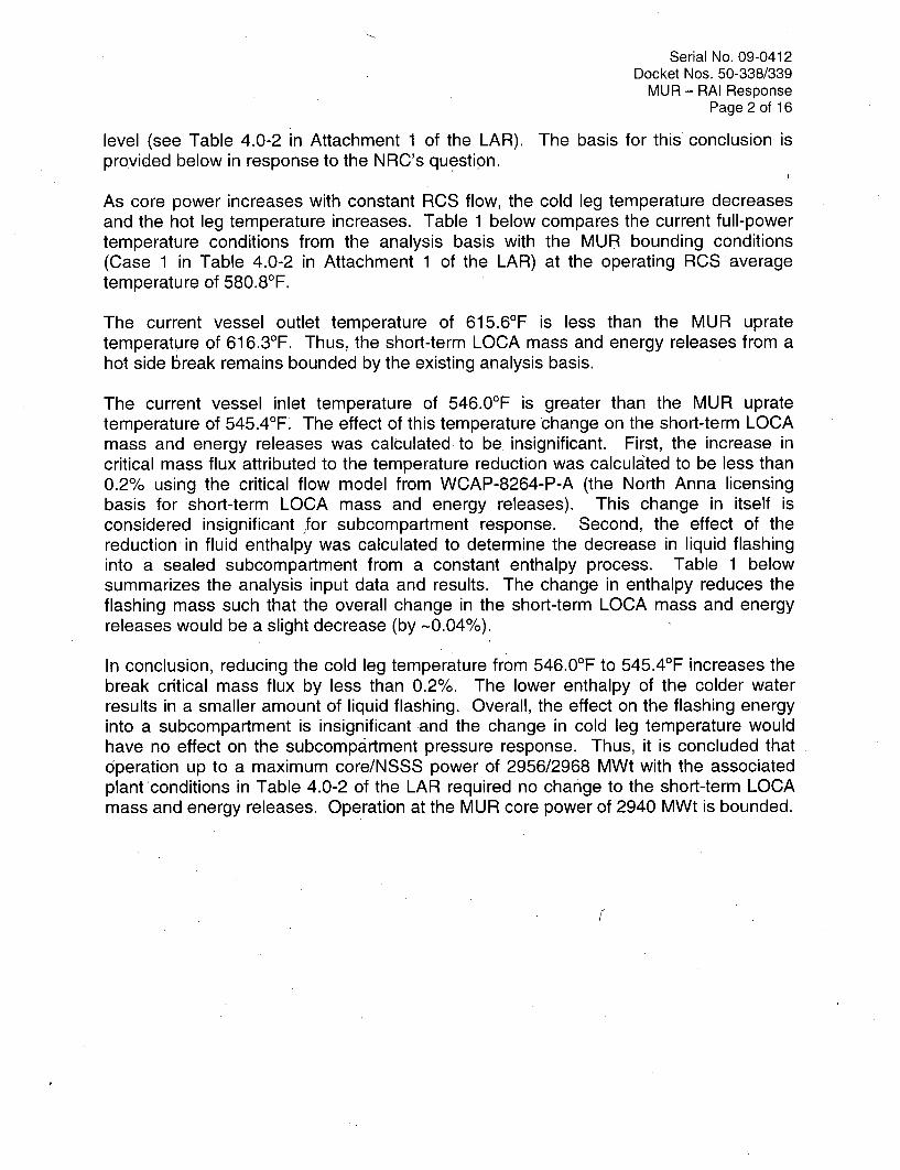
level (see Table 4.0-2 in Attachment 1 of the LAR). The basis for this conclusion isprovided below in response to the NRC's question.
As core power increases with constant RCS flow, the cold leg temperature decreasesand the hot leg temperature increases. Table 1 below compares the current full-powertemperature conditions from the analysis basis with the MUR bounding conditions(Case 1 in Table 4.0-2 in Attachment 1 of the LAR) at the operating RCS averagetemperature of 580.80F.
The current vessel outlet temperature of 615.60 F is less than the MUR upratetemperature of 616.30F. Thus, the short-term LOCA mass and energy releases from ahot side break remains bounded by the existing analysis basis.
The current vessel inlet temperature of 546.0°F is greater than the MUR upratetemperature of 545.40F. The effect of this temperature change on the short-term LOCAmass and energy releases was calculated to be insignificant. First, the increase incritical mass flux attributed to the temperature reduction was calculated to be less than0.2% using the critical flow model from WCAP-8264-P-A (the North Anna licensingbasis for short-term LOCA mass and energy releases). This change in itself isconsidered insignificant 'for subcompartment response. Second, the effect of thereduction in fluid enthalpy was calculated to determine the decrease in liquid flashinginto a sealed subcompartment from a constant enthalpy process. Table 1 belowsummarizes the analysis input data and results. The change in enthalpy reduces theflashing mass such that the overall change in the short-term LOCA mass and energyreleases would be a slight decrease (by -0.04%).
In conclusion, reducing the cold leg temperature from 546.0°F to 545.40F increases thebreak critical mass flux by less than 0.2%. The lower enthalpy of the colder waterresults in a smaller amount of liquid flashing. Overall, the effect on the flashing energyinto a subcompartment is insignificant and the change in cold leg temperature wouldhave no effect on the subcompartment pressure response. Thus, it is concluded thatoperation up to a maximum core/NSSS power of 2956/2968 MWt with the associatedplant conditions in Table 4.0-2 of the LAR required no change to the short-term LOCAmass and energy releases. Operation at the MUR core power of 2940 MWt is bounded.

Serial No. 09-0412Docket Nos. 50-338/339
MUR - RAI ResponsePage 3 of 16
Table 1: Evaluation of Cold Leg Temperature Change on Short-term Mass and Energy Releases
Reference MUR Case 1Conditions
NSSS Power, MWt 2910 2968Reactor Power, MWt 2898 2956
RCS Tavg, OF 580.8 580.8
Vessel Inlet, OF 546.0 545.4
Vessel Outlet, OF 615.6 616.3
Saturation Pressure at Vessel 1011.8 1006.8 ASME Steam TablesInlet Temperature, psia (Psat)Saturation Liquid Enthalpy at 544.4 543.6 ASME Steam TablesPsat, Btu/Ibm (href) (hmur)
Critical Mass Flux (G), 27,763.3 27,809.7 Note 1Ibm/sec-ft 2 (Gref) (Gmur)
Flow Ratio (FR) 1.00167 Gmur / GrefEnthalpy Ratio (ER) 0.99790 Note 2Total Effect = FR * ER 0.999571) Modified Zaloudek critical mass flux is calculated using the NRC-approved
methodology in WCAP-8264-P-A.2) Enthalpy ratio = (hmur - 180.2)/(href - 180.2); where 180.2 Btu/Ibm is the saturation
liquid enthalpy at a containment pressure of 14.7 psia (upper bounding initialcondition for North Anna's subatmospheric containment).
Reactor Systems
NRC Question 2
Describe and provide drawings of the location where the Ultrasonic Flow Meter (UFM)will be installed in the 3 main feedwater lines between the existing feedwater venturiflow meters and the main feedwater check valves.
Dominion Response
The basic configuration for the feedwater (FW) lines in both North Anna Units 1 and 2are similar. The lines contain, in sequence, the FW flow venturis, a 90 degree pipebend, the UFM spool piece metering sections and finally the main FW check valves.The location of the UFM spool piece metering sections can be specified relative to thecenterline of the upstream 90 degree bend. The following table provides the actualdistance downstream from the upstream bend.

Serial No. 09-0412Docket Nos. 50-338/339
MUR - RAI ResponsePage 4 of 16
tLine Distance downstream of the centerline of the feedwaterline upstream of the pipe bend
NAPS Ul A 29 feet 3 inchesNAPS Ul B 14 feet 1 inchesNAPS Ul C 24 feet 0 inchesNAPS U2 A 18 feet 1 inchesNAPS U2 B 21 feet 7 inchesNAPS U2 C 28 feet 7 inches
Drawings showing the details of the UFM location for Unit 1 and 2 are enclosed.
NRC Question 3
In section 1.1, (Application Attachment 5, Page 7), the description that spool pieces areinstalled well downstream of the existing feedwater flow venturis is unclear. Pleasequantify "well downstream" and justify that the spool pieces will have no impact- onventuri performance.
Dominion Response
The FW piping, is 16-inch, Schedule 80 pipe with a nominal inside diameter of 14.3inches. Cameron Installation and Commissioning Manual (1B0712), Section 1.1.1,requires at least five inside pipe diameters downstream of the centerline of an upstreamdisturbance. The North Anna spool piece metering sections are installed a minimum often inside pipe diameters downstream of the FW flow venturis. The installation of thespool piece metering'sections will create less than 0.015 psi of additional head loss inthe feedwater system. Because the installed location of the spool piece meteringsections is a minimum of 14 feet downstream of the centerline of the upstream FW pipebends, the impact on the venturi is insignificant.
NRC Question 4
What are the instructions for transducer replacement?
Dominion Response
Station procedures 1-ICM-FW-UFM-001 and 2-ICM-FW-UFM-001 are underdevelopment with a current completion date of July 31, 2009. These procedures arebased on Cameron Engineering Field Procedure 18 "Installation Procedure for In-LinePushrod Transducer."

Serial No. 09-0412Docket Nos. 50-338/339
MUR - RAI ResponsePage 5 of 16
NRC Question 5
In Section 1.1 .G, (Attachment 5, Page 16), a completion time of 48 hours is proposed foroperation in excess of 2893 MWth with the UFM not functional, provided thatsteady-state conditions persist throughout the 48-hour period. It is unclear how the"UFM not functional" is defined. Please describe the conditions that exist for anon-functional UFM.
Dominion Response
The North Anna Technical Requirements Manual (TRM) uses the term "functional" for asystem, structure, or component (SSC) that is not controlled by TechnicalSpecifications. An SSC is functional when it is capable of performing its specifiedfunction, as set forth in the current licensing basis. TRM 3.3.10 will provide the plantadministrative controls for the Feedwater UFM Calorimetric and was included inAttachment 4 of Dominion letter Serial No. 09-033, dated March 26, 2009. Consistentwith TRM 3.3.10, the Feedwater UFM Calorimetric shall be functional with: a) theFeedwater UFM system functional; and b) the plant computer system (PCS) calorimetricprogram functional. Thus, a failure of either the UFM system or the PCS calorimetricprogram will result in the Feedwater UFM Calorimetric being declared "not functional".The following excerpt from the Basis for TRM 3.3.10 describes the conditions that existfor a non-functional UFM.
The Feedwater UFM System performs on-line self diagnostics to verify systemoperation within design basis uncertainty limits. Any out of specification conditionwill result in a control room annunciator. A failure between the Feedwater UFMSystem electronics cabinet and the plant computer will also result in a controlroom annunciator. If the feedwater UFM failure annunciator is received, theFeedwater UFM System will be declared not functional. The control roomannunciator response procedure provides guidance to the operators for initialalarm diagnosis and response.
Although a single plane malfunction results in a minimal increase in feedwaterflow uncertainty, operators will conservatively respond to a single plane failure inthe same manner as a complete system failure. This approach will simplifyoperator response and prevent misdiagnosing a failure mode.
The TRM Basis is consistent with the plant design change that installed the feedwaterUFM system and the 6ontrol room annunciators. Section VII.2.B in Attachment 5 ofDominion letter Serial No. 09-033 dated March 26, 2009, describes the annunciatorsand that any UFM condition that increases feedwater flow uncertainty is considered aFeedwater Ultrasonic Flow Meter Failure alarm condition.

Serial No. 09-0412Docket Nos. 50-338/339
MUR - RAI ResponsePage 6 of 16
Steam Generator Tube Inteqrity and Chemical Engineering
NRC Question 6
Section 11.3.2, "Auxiliary Equipment Design Transients" (Application Attachment 5, Page47), indicates that the only auxiliary equipment design transients impacted by the poweruprate are those associated with the reactor coolant system hot and cold legtemperatures. It is further stated that the existing auxiliary equipment design transientsare conservative and bounding for the power uprate. Please discuss whether theanalysis included changes in nitrogen-16 activity that would potentially effect letdownline decay time requirements.
Dominion Response
The design transients evaluated for the MUR are thermal transients associated with thedifference between the design full power values of Thot and Tcold. Magnitude of thetransients is defined by the difference between RCS loop coolant temperature and thetemperature of coolant in the auxiliary systems connected to the RCS loops. Thisanalysis did not include the potential impact of changes in nitrogen-16 activity and itsrelationship with letdown line decay time requirements. This aspect of the MUR isdiscussed below.
The existing design basis requirement is that coolant flow leaving the RCS loop throughthe letdown line has a transit time of at least 60 seconds to reach the containmentpenetration (assuming maximum letdown flow). This delay time is required to allow fordecay of nitrogen-16. The delay depends on two key design features: 1) the letdownflowrate and 2) the total volume of piping through which flow passes between the RCSloop and the containment penetration. The letdown line decay requirement does nothave a dependence upon reactor power. Since the MUR does not affect the letdownflowrate or letdown piping volume, the specified design requirement remains satisfiedfor operation at the proposed MUR conditions.
Instrumentation and Controls
NRC Question 7
Section 1.1.G "Completion Time and Technical Basis" (Application Attachment 5, Page16) provides justification for the proposed 48 hours Allowed Outage Time (AOT) shouldthe UFM be declared inoperable. The first bullet states "Alternate instrumentationaccuracy due to nozzle fouling or transmitter drift will not significantly change over 48hours." Was transmitter drift data used to support this conclusion? Please provide thecalculated effect of the known transmitter drift on the power calorimetric calculationduring the proposed AOT.

Serial No. 09-0412Docket Nos. 50-338/339
MUR - RAI ResponsePage 7 of 16
Dominion Response
The proposed Completion Time (CT) of 48 hours was based on engineering andindustry experience with feedwater flow transmitters and consistent with the NRCapproval of a 48-hour CT for Vogtle (referenced below). The original Foxboro feedwaterflow transmitters for North Anna Units 1 and 2 were replaced with Rosemounttransmitters in fall 2007 for Unit 1 and fall 2008 for.Unit 2. Therefore, there is limiteddrift data available for these specific transmitters.
New calorimetric software to accommodate the leading edge flow meter (LEFM) isbeing installed in the Plant Computer System on both units. Once this software is inplace, the feedwater venturi normalization factors (defined as feedwater mass flow fromthe LEFM divided by the calculated feedwater mass flow from the venturis and RTD's)can be calculated, tracked, and trended for all channels. Dominion will confirm that thevariation in the flow normalization factors over a 48 hour period is negligible and that thenormalized venturi flows are an acceptable surrogate for the LEFM flows during the48-hour CT prior to any such use above 2893 MWt. Specifically, we will demonstratethat the effects of variability in the normalization factors between the UFM and venturibased flows, when statistically combined with other contributors to calorimetricuncertainty, does not produce an overall power uncertainty exceeding 0.37% (themargin between the analyzed limit of 102% of the current rating of 2893 MWt and theproposed MUR rating of 2940 MWt).
Dominion understands that, consistent with NRC practice to ensure completion ofcommitments prior to implementation of licensee amendments, this commitment andothers may be included as license conditions with the MUR license amendment.
Reference:
Letter from Siva P. Lingham (NRC) to Mr. Tom E. Tynan (Vogtle Electric GeneratingPlant), Vogtle Electric Generating Plant, Units 1 and 2, Issuance of AmendmentsRegarding Measurement Uncertainty Recapture Power Uprate (TAC Nos. MD6625and MD6626), February 27, 2008. (ML 080350347)
NRC Question 8
Section 1.1.D.3.1 "Response to NRC Criterion 3" (Application Attachment 5, Page 12),Dominion Technical Report EE-01 16 is referenced as the document that governs thecombination of errors within instrument loops relative to setpoint determination. Pleaseprovide a copy of EE-01 16. Has this report been previously reviewed by NRC? If so,please provide reference to that review.

Serial No. 09-0412Docket Nos. 50-338/339
MUR - RAI ResponsePage 8 of 16
Dominion Response
The Reactor Protection System (RPS) and Engineered Safety Features ActuationSystem (ESFAS) instrument setpoints and associated Allowable Values were derivedusing the setpoint methodology established in EE-01 16, which is consistent withMethods 1 and 2 of the Instrumentation, Systems and Automation Society's (ISA)Standard ISA-R67.04, Part II, "Methodologies for the Determination of Setpoints forNuclear Safety-Related Instrumentation." Revision 3 of EE-01 16 determined theinstrument setpoints using Methods 1 and 2 for both Surry and North Anna.
By letter dated September 19, 2007, (ADAMS Accession No. ML 072681096) Dominionprovided Technical Report EE-01 16, "Allowable Values for North Anna ImprovedTechnical Specifications (ITS), Tables 3.3.1-1 and 3.3.2-1 and the Setting Limits forSurry Custom Technical Specifications (CTS) Sections 2.3 and 3.7," Rev. 3, datedSeptember 2006, to support a license amendment to revise several setting limits forSurry Power Station. The methodology was reviewed and approved by the NRC staffand documented in NRC letter dated September 17, 2008, "Surry Power Station Units 1and 2, Issuance of Amendments Regarding the Revision to Various Setting Limits andthe Overtemperature AT/Overpower AT Time Constants (TAC Nos. MD6812 and6813)," (ADAMS Accession No. ML 082250013).
Revision 4 of EE-01 16, which was referenced in the March 26, 2009 submittal,incorporated changes to setpoints from plant changes and did not affect the setpointmethodology.
NRC Question 9
The steam enthalpy values presented in Item 7 of Table I-1 (Application, Attachment 5,Page 14), ER-646/Rev. 2 and ER-637/Rev. 3 for the NAPS 1 and 2 total thermal poweruncertainty determination appear to be consistent with zero-moisture steam perER-1 57P/Rev. 5. Please verify that the zero moisture steam condition is appropriate forNAPS 1 and 2.
Dominion Response
Table 1 in ER-157P, Revision 5, identifies two values for the uncertainty of steamenthalpy with the LEFM CheckPlus system. The bounding uncertainty of ± 0.22%power assumes an uncertainty of ± 0.25% in steam moisture about an assumedmoisture of 0.25% (i.e., 100% uncertainty). Footnote 7 on Table 1 of ER-157P,Revision 5, supports a reduced uncertainty of 0.07% "if moisture carryover is knownmore accurately or if the steam is conservatively assumed to carry zero moisture in theheat balance calculation." Thus, there are two possibilities that can support a reduceduncertainty for steam enthalpy.

Serial No. 09-0412Docket Nos. 50-338/339
MUR - RAI ResponsePage 9 of 16
North Anna Units 1 and 2 include a steam moisture carryover (MCO) uncertainty of0.08% moisture in the power calorimetric uncertainty calculation. Using this MCOuncertainty, a steam moisture contribution for power uncertainty of 0.013% ratedthermal power (RTP) was developed. This value was combined with a steam pressurecontribution to power uncertainty of 0.051% rated thermal power (RTP) to develop aplant-specific uncertainty for steam enthalpy of 0.053% RTP (presented as 0.05% inTable I-1 of the LAR). The steam moisture and pressure uncertainties are Items 20 and21, respectively, in Table B-1 of ER-646, Revision 2 (Unit 1) and ER-637, Revision 3(Unit 2) of Attachments 2 and 3, respectively, of our submittal dated March 26, 2009(Serial No. 09-033A).
During the review of the plant-specific uncertainties calculation for this question,Dominion identified that the steam moisture uncertainty of 0.013% RTP that was used inthe total thermal power uncertainty calculation was incorrect. The corrected steammoisture contribution to power uncertainty is 0.040% RTP. In response to this error, theplant-specific uncertainties calculation was revalidated completely and two small errorswere identified that increase the Gains/Losses uncertainty from 0.087% RTP to 0.092%RTP [(Item 22 in Table B-1 of ER-646, Revision 2 (Unit 1) and ER-637, Revision 3 (Unit2)].
The Cameron uncertainty calculations (ER-646 for Unit 1 and ER-637 for Unit 2) wererevised with a steam moisture contribution to power uncertainty of 0.040% and aGains/Losses uncertainty of 0.092%. The total thermal power uncertainty increasedfrom 0.351% to 0.354% for Units 1 and 2. Both values remain less than the accidentanalysis allowance of 0.37%.
The impact on the contents of the LAR that was submitted by Dominion letter (SerialNo. 09-033) dated March 26, 2009, is detailed below.
* The overall power level measurement uncertainty was reported as 0.35% at RTPon page 3 of Attachment 1 and on pages 8, 13, 14 and 21 of Attachment 5. Thiswas a rounded value based on the original total power uncertainty of 0.351% RTP.The revised calculations produce a total power uncertainty of 0.354% RTP.Conservatively, this value would be rounded up to 0.36% RTP. The UFM-basedcalorimetric uncertainty remains less than the 0.37% RTP allowance in thedeterministic accident analysis with a licensed power level of 2940 MWt.Therefore, the conclusion on page 21 of Attachment 5 that the deterministicaccident analyses remain bounding is unaffected by the revised uncertaintycalculations.
• The steam enthalpy uncertainty presented as Item 7 in Table I-1 on page 14 ofAttachment 5 increases from 0.05% to 0.07% with the steam moisture contributionto power uncertainty of 0.040% RTP. The Gains/Losses uncertainty presented asItem 8 in Table 1-1 of Attachment 5 is unchanged from 0.09%.

Serial No. 09-0412Docket Nos. 50-338/339
MUR - RAI ResponsePage 10 of 16
The Cameron uncertainty calculations (ER-646, Revision 2 for Unit 1 and ER-637,Revision 3 for Unit 2) were provided as Attachments 2 and 3 of Dominion letter (SerialNo. 09-033A) dated March 26, 2009. The thermal power uncertainty calculations havebeen revised to correct the non-conservative plant-specific uncertainties describedabove. Dominion is providing, in Attachment 3, the revised pages from ER-646,Revision 3 (Unit 1), and ER-637, Revision 4 (Unit 2).
Electrical Engineering
NRC Question 10
In Section 111.2.A "Normal Operation" (Application Attachment 5, Page 57), the licenseestates that the normal operation radiation dose levels increase as a result of the MURpower uprate for the reactor vessel excore neutron detectors and the qualified life of theexcore detectors may be decreased. Furthermore, the licensee concludes that thepreliminary results indicate no impact on radiation dose margin or qualified life of theexcore detectors. Confirm that these calculations have been completed and that thereis no impact on the radiation dose margin or qualified life of the excore detectors.
Dominion Response
As noted in our March 26, 2009 submittal (Serial No. 09-033), in RegulatoryCommitment 10, Dominion committed to determine the EQ service life of the excoredetectors prior to operating above 2893 MWt. The current schedule for completion ofthis commitment is September 30, 2009.
Dominion understands that, consistent with NRC practice to ensure completion ofcommitments prior to implementation of licensee amendments, that this commitmentand others may be included as license conditions with the MUR license amendment.
NRC Question 11
In Section V.1.D.ii "Proposed New Generation Impact Analysis" (Application,Attachment 5, Page 101), the licensee states that the local generation study assessedstation operation at maximum capability, and that the study identified no transmissiondeficiencies. Furthermore, the study indicated no decrement to system FirstContingency Incremental Transfer Capability. The licensee states that in the summarysection of the PJM impact studies, the maximum facility output is 945 MWe for Unit 1and 938 MWe for Unit 2. Explain the results of this study and how the results are validfor the power uprate since Section V.1.F.i "Main Generator" (ADAMS Accession No.ML090900055, Attachment 5, Page 102), states that the output of the generators will be980.5 MWe for Unit 1 and 972.9 MWe for Unit 2.

Serial No. 09-0412Docket Nos. 50-338/339
MUR - RAI ResponsePage 11 of 16
Dominion Response
Section V.1.F.i has been revised as follows to provide explanation of the PJM impactstudies. The revisions are highlighted in bold type. Please use the following revisedLAR Section V.1 .F.i Main Generator to complete your review:
V.1.F.i Main Generator
Unit 1
The nameplate rating is 1105 MVA (based on 75 psig hydrogen pressure), 0.900 powerfactor, and 22 kV. The generator is operated with restrictions not to exceed 475 MVARsout or 390 MVARs in, and maintain generator load and hydrogen pressure within thelimits of the Generator Calculated Capability Curve with a generator rating of 1088.6MVA. The main generator output at the current NSSS power level of 2905 MWt is 965MWe. The anticipated main generator output is 980.5 MWe based on the heat balanceat MUR uprate conditions. The generator capability curve indicates that at 980.5 MWe,the generator is capable of exporting 472.9 MVAR (lagging power factor of 0.900) andimporting approximately 390 MVAR (leading power factor of 0.929). However, the980.5 MWe for Unit 1 is a gross MWe value and does not take into account theapproximate 48 MWe of internal electrical loads the plant represents to thegenerator output for each unit. Subtracting the 48 MWe of internal electricalloads from Unit 1 heat balance value of 980.5 MWe yields a net maximum facilityoutput of 932.5 MWe, which is below the 945 MWe value in the PJM study(Attachment 5, Section V.1.D.ii). The exciter has the capability to support maingenerator operation within its restricted operational rating and within the capability curvefor leading and lagging power factor. Therefore, the increase from the MUR poweruprate remains below the main generator maximum capability and the maximumfacility output for Unit 1 is still bounded by the PJM studies.
Unit 2
The Unit 2 main generator was replaced during the September 2008 outage. Theexciter and voltage regulator were not replaced. The new nameplate rating is 1200MVA (based on 75 psig hydrogen pressure), 0.900 power factor, and 22 kV. Thegenerator is operated with restrictions not to exceed 444 MVARs out or 210 MVARs inand to maintain generator load and hydrogen pressure within the limits of GeneratorCalculated Capability Curve with a generator rating of 1088.6 MVA. The maingenerator output at the current NSSS power level of 2905 MWt is 965 MWe. Theanticipated main generator output is 972.9 MWe based on the heat balance at MURuprate conditions. The generator capability curve indicates that at 972.9 MWe, thegenerator is capable of exporting approximately 444 MVAR (lagging power factor of0.910) and importing approximately 210 MVAR (leading power factor of 0.977).However, the 972.9 MWe for Unit 2 is gross MWe value and does not take intoaccount the approximate 48 MWe of internal electrical loads the plant represents

Serial No. 09-0412Docket Nos. 50-338/339
MUR - RAI ResponsePage 12 of 16
to the generator output for each unit. Subtracting the 48 MWe of internalelectrical loads from Unit 2 heat balance value of 972.9 MWe yields a netmaximum facility output of 924.9 MWe, which is below the 938 MWe value in thePJM study (Attachment 5, Section V.1.D.ii). The exciter has the capability to supportmain generator operation within its restricted operational rating and within the capabilitycurve for leading and lagging power factor. Therefore, the increase from the MURpower uprate remains below the main generator maximum capability and themaximum facility output for Unit 2 is still bounded by the PJM studies.
NRC Question 12
Provide the uprated loadings of the reserve station service transformers. Also, providethe ratings and the uprated loadings of the plant main transformers, and unit stationservice transformers.
Dominion Response
Reserve Station Service Transformers
The uprated loadings of the reserve station service transformers follow:
RSST A: 19.0 MVARSST B: 29.7 MVARSST C: 30.5 MVA
Main Transformers
The ratings of the main transformers are 1200 MVA. The uprated loadings of the maintransformers are 1088.6 MVA minus the station service transformer loadings.
Station Service Transformers
The ratings of the station service transformers are 22.4 MVA. The uprated loadings ofthe station service transformers follow:
Unit 1 Unit 2SST 1A: 19.3 MVA SST 2A: 19.6 MVASST 1 B: 19.2 MVA SST 2B: 18.6 MVASST 1C: 18.8 MVA SST 2C: 18.8 MVA
The transformer loadings provided in this response are based on the MUR upratedpower conditions. Dominion is planning turbine replacement projects for North AnnaUnits 1 and 2, which will also affect the transformer loading values and the PJM GridStability Study. Similar engineering analysis will be performed to support the turbinereplacements and the associated increased electrical generation. The turbine

Serial No. 09-0412Docket Nos. 50-338/339
MUR - RAI ResponsePage 13 of 16
replacement project is independent of the MUR uprate. The supporting analysis for theturbine replacements is ongoing and scheduled to be completed in approximately sixmonths for Unit 2 and two years for Unit 1. Based on the fabrication schedule for theturbines, the replacements are currently scheduled to be completed during refuelingoutages between 2010 and 2012.
Mechanical and Civil Engineering
NRC Question 13
In Section IV.1.A.v, "Balance-of-Plant Piping" (Application Attachment 5, Page 74), thelicensee did not specify which Balance-of-Plant Piping systems were reviewed insupport of the proposed power uprate. Please provide a list of these systems.
Dominion Response
The following North Anna Nuclear Power Station Units 1 and 2 balance of plant (BOP)and nuclear steam supply system (NSSS) interface piping systems were evaluated forMUR uprate conditions:
BOP Piping Systems NSSS Interface Pipina Systems
* Main Steam and Steam DumpSystem
• Moisture Separator & Reheater DrainSystem
• Feedwater System• Condensate System" Extraction Steam System• High Pressure Feedwater HeaterDrains System
* Low Pressure Feedwater HeaterDrains System
* Gland Steam and Leak-off System" Auxiliary Feedwater System" Fuel Pool Cooling and PurificationSystem
* Containment Spray (QSS and RSS)System
" Circulating Water System* Auxiliary Steam System* Chilled Water System• Gaseous Waste System* Liquid Waste System• Service and Instrument Air System
* Chemical and Volume Control System" Residual Heat Removal System• Safety Injection System" Pressurizer Spray System* Pressurizer Safety Relief Valve andPower Operated Relief Valve Systems

Serial No. 09-0412Docket Nos. 50-338/339
MUR - RAI ResponsePage 14 of 16
Fire protection
NRC Question 14
In Section 11.2.36, "Safe Shutdown Fire Analysis (Appendix R Report) - UFSAR 9.5.1,"(Application, Attachment 5, Page 45), states that "...Operator actions in response to anAppendix R fire are not adversely impacted..." The staff requests the licensee to verifythat (1) the MUR power uprate will not require any new operator actions, and (2) anyeffects from additional heat in the plant environment from the increased power will notinterfere with existing operator manual actions being performed at their designated timeand place.
Dominion Response
Section VII.1 of Attachment 5 of Dominion letter (Serial No. 09-033), datedMarch 26, 2009, summarizes the review of the operator actions assumed in the safetyanalyses, including the Appendix R fire safe shutdown analyses. The Appendix R firesafe shutdown analyses were reviewed for the MUR power uprate and the conclusionsin Section VII.1 apply: 1) existing operator actions are not affected; 2) no reduction inoperator action time was identified; 3) no new operator actions were identified; and 4)no existing manual actions were automated.
The temperature and pressure parameters outside of containment will not be impacted,by implementation of the MUR. Therefore, Appendix R manual actions outsidecontainment are not affected by additional heat in the plant environment from theincreased power.
A review of Fire Contingency Action (FCA) procedures 1/2-FCA-5 shows that there areno manual actions required inside containment to prevent or maintain safe shutdown.There is one manual action listed as a contingency in the event that less than oneresidual heat removal (RHR) pump is available: repair of RHR cable. This manualaction would be required for cold shutdown approximately 55 hours after the fireinitiating event. The fire extinguishment and hot shutdown time is approximately onehour. Therefore, this action inside containment is not affected by additional heat in theplant environment from the increased power.
Any effects from additional heat in the plant environment from the increased power willnot interfere with existing operator manual actions being performed at their designatedtime and place.
NRC Question 15
Some plants credit aspects of their fire protection system for other than fire protectionactivities, e.g., utilizing the fire water pumps and water supply as backup cooling or

Serial No. 09-0412Docket Nos. 50-338/339
MUR - RAI ResponsePage 15 of 16
inventory for non-primary reactor systems. If the NAPS 1 and 2 credits its fire protectionsystem for other than fire protection activities, please identify the specific situations anddiscuss to what extent, if any, the MUR power uprate affects these "non-fire-protection"aspects of the plant fire protection system. If the NAPS 1 and 2 do not take such credit,please verify this as well.
Dominion Response
The North Anna Fire Protection System is not credited or required to mitigate theconsequences of Design Basis Accidents. However as noted in UFSAR Chapter 9.5, inaddition to its primary function, which is to permit safe shutdown of the plant in the eventof a fire, the fire protection system also provides alternate sources of makeup water forthe spent-fuel pool and for the Unit 1 and Unit 2 auxiliary feedwater systems. Inaccordance with BTP-APCSB 9.5-1, Appendix A, Paragraph A.4, postulated fires neednot be considered concurrently with other plant accidents. Therefore, these secondaryfunctions of the fire protection system do not prohibit the system from performing itsprimary function. The fire protection system's capacity remains adequate to providesecondary functions (i.e., backup water to the auxiliary feedwater pumps or makeupwater to the spent fuel pool) at the uprated power. In addition, the Fire ProtectionSystem is used in B.5.b Mitigating strategies as a method to supply makeup water tovarious systems. The MUR has no impact on the ability of the Fire Protection System tomeet the makeup requirements of the mitigating strategies.
Accident Dose
NRC Question 16
The discussion of the Waste Gas Decay Tank Rupture UFSAR 15.3.5 in Section 11.2.19,(Application, Attachment 5, Page 36), refers to a calculation that indicates 1.6 rem at the.exclusion area boundary. Although this value meets the Part 100 limit of 25 rem wholebody which was originally used for tank rupture accidents, more recent guidance limitsthe dose to 500 mrem whole body or 100 mrem TEDE. The NRC staff notes that TSSection 5.5.11, "Explosive Gas and Storage Tank Radioactivity Monitoring Program,"item b, states that, "A surveillance program to ensure that the quantity of radioactivitycontained in each gas storage tank is less than the amount that would result in a wholebody exposure of ->0.5 rem to any individual in an unrestricted area, in the event of anuncontrolled release of the tanks' contents ... " Provide additional information describingwhether the Explosive Gas and Storage Tank Radioactivity Monitoring Program appliesto the Waste Gas Decay Tank Rupture and if so why this program is not cited as thebases for making the determination that the MUR will not change the accidentevaluation.

Serial No. 09-0412Docket Nos. 50-338/339
MUR - RAI ResponsePage 16 of 16
Dominion Response
Dominion agrees that the information in LAR section 11.2.19 and TS 5.5.11 could beconsidered an inconsistency in the discussion of dose consequences from the ruptureof a Waste Gas Decay Tank. As described in Section 11.2.19, the dose consequenceanalysis of the Waste Gas Decay Tank Rupture results in 1.6 rem at the exclusion areaboundary (EAB). This conservative analysis is part of the original plant licensing basiswhich will be maintained in the UFSAR. The Explosive Gas and Storage TankRadioactivity Monitoring Program defined in TS 5.5.11 describes a station surveillanceprogram that ensures that the quantity of radioactivity contained in the gas storage tankis less than the amount that would result in a whole body exposure of > 0.5 rem to anyindividual in an unrestricted area, in the event of an uncontrolled release of the tanks'contents. Discussion of this surveillance program will be included in LAR section 11.2.19as follows to provide a strong, defendable position that the MUR will have no impact onthis accident.
From the March 26, 2009 submittal:
"11.2.19 Waste Gas Decay Tank Rupture - UFSAR 15.3.5
The waste gas decay tank rupture analysis was part of the original plant licensing basis.The analysis resulted in an exclusion area boundary whole body dose of 1.6 rem, whichis reported in UFSAR Section 15.3.5 and compared to the 10 CFR 100 acceptancecriterion. The 10 CFR 100 acceptance criterion for waste gas decay tank ruptureexclusion area boundary whole body dose was 25 rem. Conservatisms in theradiological atmospheric dispersion factor (X/Q), dose conversion factors, and gapactivities that were used in the analysis are such that the MUR power uprate impact onthe waste gas decay tank rupture accident consequences is bounded."
Please use the following revised LAR section 11.2.19 to complete your review:
"11.2.19 Waste Gas Decay Tank Rupture - UFSAR 15.3.5
The Explosive Gas and Storage Tank Radioactivity Monitoring Program defined in TS5.5.11 limits the quantity of radioactivity contained in a waste gas decay tank to lessthan an amount that would result in a whole body exposure of -> 0.5 rem to anyindividual in an unrestricted area in the event of an uncontrolled release of the tank'scontents. The reported dose consequence of a waste gas decay tank rupture inUFSAR Section 15.3.5 is 1.6 rem which is part of the original plant licensing basis thatcomplied with the 10 CFR 100 acceptance criterion of 25 rem to the exclusion areaboundary. Due to the control of the tank's radioactive contents per the surveillanceprogram defined in TS 5.5.11, the waste gas decay tank rupture accident isindependent of power level. The surveillance program restricts the consequences of atank rupture to < 0.5 rem, which is below the calculated value of 1.6 rem reported inUFSAR Section 15.3.5. Therefore, the MUR will have no impact on this accident."

Serial No. 09-412Docket Nos. 50-338/339
MUR - RAI Response
Enclosure
Feedwater Line Drawings

,II I'I I I
' I ..- .. I . I... . I' I / I I' I I I
i III
•v' I
' I I , -,
* , VETRU ' I
•l I ItI l
"TI iSI ,I.I I
i'I II ,'% ,,,.E•I ,
'I II I
' III' I
SI ,0'DETAIL FROM UNIT I PROJECT DRAWING N-07012-1-IFP2C REV. I

I!I!
, I!
I I A!I!I!I!
I!I
,.
m
0 -
U@_
ft
0-
VENTURISI.
I UFM'sI
SI
0! 0I!
DETAIL FROM.UNIT 2 STATION DRAWING 12050-FP-2B

Serial No. 09-412Docket Nos. 50-338/339
MUR - RAI Response
ATTACHMENT 2
REVISED PAGESLICENSE AMENDMENT REQUEST
MEASUREMENT UNCERTAINTY RECAPTURE POWER UPRATE
5 Pages
VIRGINIA ELECTRIC AND POWER COMPANY (DOMINION)NORTH ANNA POWER STATION UNITS 1 AND 2

Serial No. 09-033Docket Nos. 50-338/339
Attachment 1, Page 3
models. The NRC approved a change to the 10 CFR 50, Appendix Krequirements on June 1, 2000 effective July 31, 2000. This changeprovided licensees the option of maintaining the 2% power margin betweenlicensed power level and the ECCS evaluation assumed power level, orapplying a reduced ECCS evaluation margin based on an accounting ofuncertainties due to instrumentation error.
Implementing the feedwater UFM (Cameron LEFM CheckPlus System) isan effective way to obtain additional plant power without significantlychanging current reactor core operations. Feedwater flow measurementuncertainty is the most significant contributor to core power measurementuncertainty. The UFM provides a more accurate measurement offeedwater flow and thus reduces the uncertainty in the feedwater flowmeasurement. This reduced uncertainty, in combination with otheruncertainties, results in an overall power level measurement uncertainty of0.36% at RTP.
The UFM will provide on-line main feedwater flow and temperaturemeasurement to determine reactor thermal power. This system usesacoustic energy pulses to determine the main feedwater mass flow rateand temperature. The UFM consists of a measuring section containing16 ultrasonic multi-path transit time transducers, one dual resistancetemperature detector (RTD), and two pressure transmitters installed ineach of the three feedwater lines, and an electronic signal processingcabinet.
The UFM will be used in lieu of the current venturi-based feedwater flowindication and RTD temperature indication to perform the plant calorimetricmeasurement calculation. The currently installed venturi-based feedwaterflow instruments will continue to provide inputs to other indication,protection and control systems, and will be used if the UFM is notfunctional.
3.0 PROPOSED CHANGE
The proposed (marked-up) Operating License (OL) and TechnicalSpecifications (TS) changes are provided in Attachment 2. The typed OLand TS pages are provided in Attachment 3.
The proposed OL and TS changes are described below.
Operating License - Maximum Power Level
Paragraph 2.C(1), "Maximum Power Level," of the Unit 1 and Unit 2Operating Licenses (NPF-4 and NPF-7 respectively) authorizes facilityoperation at a reactor core power level not in excess of 2893 megawatts

Serial No. 09-033Docket Nos. 50-338/339
Attachment 5, Page 8
between pulses to determine the fluid velocity. The UFM also measures the speedof sound in water and uses this measurement to determine the feedwatertemperature.
The electronic cabinet controls magnitude and sequences transducer operation;makes time measurements; and calculates volume, temperature and mass flow.The system software employs the ultrasonic transit time method to measurevelocities at precise locations. The system numerically integrates the measuredvelocities. The system software has been developed and maintained under averification and validation program. The verification and validation program hasbeen applied to the system software and hardware, and includes a detailed codereview. The feedwater mass flow rate and temperature are displayed on theelectronic cabinet and transmitted to the plant process computer for use in thecalorimetric measurement (secondary plant energy balance) of reactor thermaloutput. The system will utilize continuous calorimetric power determination bydirect, redundant links with the plant computer, and will incorporateself-verification features. These features ensure that system performance isconsistent with the design basis.
The system has two modes of operation: Normal operation and Maintenancemode. Normal operation is defined as CheckPlus operation. In this mode, bothplanes of transducers are in service and system operations are processed by bothCPUs. If the system is subjected to a failure involving a transducer, failure of oneplane of operation or if a central processing unit (CPU) related malfunction occurs,the system reverts to the Check system or Maintenance mode. When a plane ofoperation is lost, the system alerts the control room operators through theannunciator window for Feedwater Ultrasonic Flow Meter Failure, and shifts fromNormal operation to Maintenance mode. If the system suffers a loss of AC poweror other total failure, the system also alerts the operators through theaforementioned annunciator. Operations personnel are also alerted to systemtrouble through annunciator window for Feedwater Ultrasonic Flowmeter Troubleif the electronic cabinet internal temperature is high or when other troubleconditions occur as determined by the plant computer.
The improved measurement accuracy for feedwater mass flow and temperatureand a change in the way instrument uncertainty is combined for other parameters(e.g., steam temperature) results in a total uncertainty of 0.36% at RTP. This ismore accurate than the nominal 2% RTP used in the accident analyses or theuncertainty currently obtainable with precision, venturi-based instrumentation andRTDs.
The UFM indications of feedwater mass flow and temperature will be directlysubstituted for the existing venturi-based flow and RTD temperature inputscurrently used in the plant calorimetric measurement calculations. The plantcomputer system calorimetric programs will be revised to receive data from theUFM and from loop-specific, high-capacity SG blowdown flow, to calculate UFM

Serial No. 09-033Docket Nos. 50-338/339
Attachment 5, Page 13
test data were prepared. The calibration factor used for the UFM is based onthese reports. The spool piece calibration factor uncertainty is based on theCameron engineering reports. The site specific uncertainty analysis documentsthese analyses and will be maintained as part of the NAPS technical basis for thepower uprate.
Final site-specific uncertainty analyses acceptance will occur after completion ofthe commissioning process. The commissioning process verifies boundingcalibration test data and provides final positive confirmation that actual fieldperformance meets the uncertainty bounds established for the instrumentation.Final commissioning is expected to be completed by March 2010.
I.1.E Total Power Measurement Uncertainty at North Anna Units I and 2
The overall thermal power uncertainty using the UFM is 0.36% at RTP. Theuncertainty calculations for North Anna Units 1 and 2 are documented inReferences 1-6 and 1-7, which are Cameron proprietary documents that will betransmitted to the NRC via separate proprietary letter from Dominion. The keyparameters and their uncertainty are summarized in Table 1-1. In addition to thecalorimetric inputs provided by the UFM for determination of feedwater mass flowrate and enthalpy, the North Anna plant computer uses several process inputs(e.g., charging flow, letdown flow, steam generator blowdown flow) to calculatethe contribution of steam enthalpy and other gains and losses that are identifiedas Items 7 and 8 in Table I-1. For comparison, baseline values fromCameron ER-1 57P, Revision 5 (Reference 1-2) are presented in Table 1-1.Differences between the North Anna uncertainties and those from ER-1 57P,Revision 5 are a result of plant-specific calculations and parameter uncertainties.
The uncertainty for transducer installation, as identified in Cameron CustomerInformation Bulletin CIB-125 (Reference 1-10), has been included in the UFMuncertainty for North Anna Unit 1 (Reference 1-6) and North Anna Unit 2(Reference 1-7). These system uncertainties incorporate an additional transducervariability uncertainty in both the profile factor uncertainty and in the installationuncertainty.

Serial No. 09-033Docket Nos. 50-338/339Attachment 5, Page 14
Table I-1Total Thermal Power Uncertainty Determination for North Anna Units I and 2
ER-1 57P,Rev. 5 Unit 1 Unit 2
Item Parameter(1 ) Uncertainty Uncertainty Uncertainty
1 Hydraulics: Profile factor 0.25% 0.20% 0.19%
Geometry:2 Spool dimensions 0.10% 0.15% 0.16%Spool piece alignment
Spool piece thermal expansion
Time Measurements3 Time of Flight Measurements 0.05% 0.15% 0.15%
Non-fluid delay
Feedwater Density(2) (4)
4 Feedwater Density/Correlation 0.07% 0.07% 0.07%Feedwater Density/TemperatureFeedwater Density/Pressure
5 Subtotal: Mass Flow Uncertainty 0.28% 0.30% 0.30%:(Root Sum Square of Items 1-4)
Feedwater Enthalpy(3) (4) 0.08% 0.09% 0.09%Feedwater Enthalpy/Temperature
6 Feedwater Enthalpy/Pressure
Power Uncertainty, Thermal Expansion 0.12% 0.12% 0.12%.
7 Steam Enthalpy: Pressure input and 0.07% 0.07% 0.07%moisture uncertainty
8 Gains/Losses 0.07% 0.09% 0.09%
9 Total Thermal Power Uncertainty 0.33% 0.36% 0.36%
1. Items 1 through 6 are directly associated with the UFM. Items 7 and 8 are based onother plant process inputs.
2. Density errors due to the density correlation, the UFM feedwater temperaturedetermination and the feedwater pressure measurement.
3. Enthalpy errors due to the enthalpy correlation, the UFM feedwater temperaturedetermination and the feedwater pressure measurement.
4. The bounding uncertainties in pressure and temperature are +15 psi and +0.570F,respectively.
I1

Serial No. 09-033Docket Nos. 50-338/339
Attachment 5, Page 21
flooding, station blackout, ATWS). The UFSAR review was conducted to confirmthat the existing analyses of record, as currently presented in the UFSAR, wereperformed conservatively and remain valid and bounding for the proposed poweruprate. Table I1-1 indicates the analysis power levels used for the NAPS MURpower uprate.
Table I1-1Analysis Power Levels for North Anna Units I and 2 MUR Uprating
Core Power NSSS PowerAnalysis Scope MWt MWt(4) Source
NSSS 2956(1) 2968 Design Parameters
Safety Analyses 2951(2) 2963 UFSAR Chapters 6and 15
Statistical DNBR 2942.2(3) 2955 UFSAR Chapter 15Events
1. 102% of current analyzed core power of 2898 MWt2. 102% of current RTP of 2893 MWt3. 101.7% of current RTP of 2893 MWt4. The analyses use 12 MWt for RCP net heat addition.
The analyses generally model the core and/or NSSS thermal power in one ofthree ways. First, some analyses apply a 2.0% increase to the initial power levelto account for the power measurement uncertainty. These analyses have notbeen re-performed for the MUR uprate conditions, because the sum of theproposed core power level and the decreased power measurement uncertaintyfalls within the previously analyzed conditions. The existing 2.0% uncertainty isreallocated so a portion is applied to uprate power and the remainder is retainedto accommodate the power measurement uncertainty. Second, some analysesemploy a nominal power level. These analyses have either been evaluated orre-performed for the proposed power level. Third, some of the analyses areperformed at 0% power conditions or do not actually model core power level.These analyses have not been re-performed because they are unaffected by thecore power level.
For the NAPS MUR power uprate, a core RTP of 2940 MWt was selected basedon the calorimetric uncertainty of 0.35% with the UFM and a review of theaccident analysis assumptions for core power. The deterministic accidentanalyses use 2951 MWt (102% of 2893 MWt) as the total core power, whichleaves 11 MWt of margin to accommodate the power uncertainty. The 11 MWt is0.37% of 2940 MWt. Since the power calorimetric uncertainty of 0.36% at RTPwith the UFM is less than the accident analysis allowance of 0.37% with a2940 MWt licensed power level, the deterministic accident analyses are bounding