Embed Size (px)
Citation preview

North American Service Manual
MODEL PC SERIES
Version 2 March 25, 1997
Revision B1.1 April 4, 2000
Prepared byTRANSCELL TECHNOLOGY, INC.

i
TABLE OF CONTENTS
Page
Chapter 1: Introduction............................................................................................................... 1-1
Chapter 2: Legal for Trade Sealing ............................................................................................ 2-1
2.1 Overview .................................................................................................................. 2-1
2.1.1 Sealing the Scale ......................................................................................... 2-1
Chapter 3: General Troubleshooting Flowchart .......................................................................... 3-1
Chapter 4: Illustrated Parts List .................................................................................................. 4-1
4.1 PC-30 & PC-70......................................................................................................... 4-1
4.2 PC-150 ..................................................................................................................... 4-3
Chapter 5: Assembly / Disassembly ........................................................................................... 5-1
5.1 PC-30 & PC-70......................................................................................................... 5-1
5.2 PC-150 ..................................................................................................................... 5-2
Chapter 6: Internal Wiring Diagram............................................................................................ 6-1
Chapter 7: Theory of Operation.................................................................................................. 7-1
7.1 Theory of Operation Overview.................................................................................. 7-1
7.1.1 Main Board Assembly .................................................................................. 7-1
7.1.2 Display/Key Board Assembly........................................................................ 7-1
Appendix A: Technical Specifications ........................................................................................... A-1
Appendix B: Serial Data Formats Information ............................................................................... B-1
B.1 Serial Data Formats.................................................................................................. B-1
B.1.1 Serial Data Formats Overview ..................................................................... B-1
B.1.2 Consolidated Controls Demand Format........................................................ B-1
B.1.2.1 Recognized Host Commands ......................................................... B-1
B.1.3 Consolidated Controls Continuous Format.................................................... B-2
B.1.4 Toledo 8213 Demand Format....................................................................... B-3
B.1.4.1 Recognized Host Commands ......................................................... B-3
B.1.5 NCI 3800 / Triner Demand Format ............................................................... B-4
B.1.5.1 Recognized Host Commands ......................................................... B-4
B.1.6 Transcell Technology Demand Format......................................................... B-5
B.1.6.1 Recognized Host Commands ......................................................... B-5
B.1.7 Transcell Technology Continuous Format..................................................... B-6
B.1.8 Detecto Demand / Continuous Format.......................................................... B-7
B.1.8.1 Recognized Host Commands ......................................................... B-7
ii
B.1.9 Fairbanks 70-2453-4 Demand Format .......................................................... B-8
B.1.9.1 Recognized Host Commands ......................................................... B-8
Appendix C: Circuit Diagrams....................................................................................................... C-1
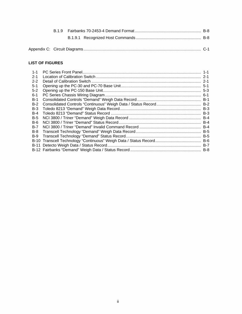
LIST OF FIGURES
1-1 PC Series Front Panel........................................................................................................ 1-12-1 Location of Calibration Switch ............................................................................................ 2-12-2 Detail of Calibration Switch ................................................................................................ 2-15-1 Opening up the PC-30 and PC-70 Base Unit ...................................................................... 5-15-2 Opening up the PC-150 Base Unit...................................................................................... 5-36-1 PC Series Chassis Wiring Diagram .................................................................................... 6-1B-1 Consolidated Controls “Demand” Weigh Data Record ........................................................ B-1B-2 Consolidated Controls “Continuous” Weigh Data / Status Record....................................... B-2B-3 Toledo 8213 “Demand” Weigh Data Record....................................................................... B-3B-4 Toledo 8213 “Demand” Status Record ............................................................................... B-3B-5 NCI 3800 / Triner “Demand” Weigh Data Record ............................................................... B-4B-6 NCI 3800 / Triner “Demand” Status Record........................................................................ B-4B-7 NCI 3800 / Triner “Demand” Invalid Command Record ...................................................... B-4B-8 Transcell Technology “Demand” Weigh Data Record ......................................................... B-5B-9 Transcell Technology “Demand” Status Record.................................................................. B-5B-10 Transcell Technology “Continuous” Weigh Data / Status Record........................................ B-6B-11 Detecto Weigh Data / Status Record.................................................................................. B-7B-12 Fairbanks “Demand” Weigh Data / Status Record .............................................................. B-8
1-1
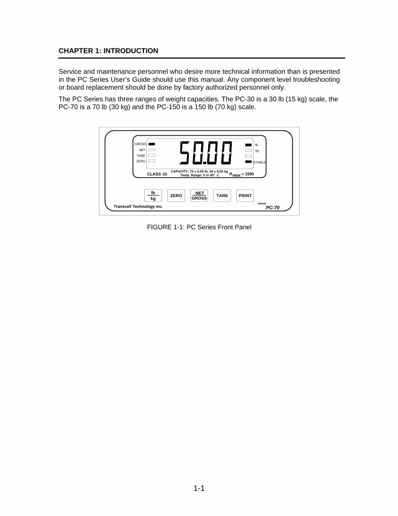
CHAPTER 1: INTRODUCTION
Service and maintenance personnel who desire more technical information than is presentedin the PC Series User’s Guide should use this manual. Any component level troubleshootingor board replacement should be done by factory authorized personnel only.
The PC Series has three ranges of weight capacities. The PC-30 is a 30 lb (15 kg) scale, thePC-70 is a 70 lb (30 kg) and the PC-150 is a 150 lb (70 kg) scale.
PC-70MODEL
ZEROkglb
GROSSNET TARE PRINT
Transcell Technology inc.
CLASS = 1500maxnIIICAPACITY: 70 x 0.05 lb, 30 x 0,02 kg
Temp. Range: 0 to 40° C
ZERO
TARE
NET
GROSS
STABLE
lb
kg
FIGURE 1-1: PC Series Front Panel
2-1
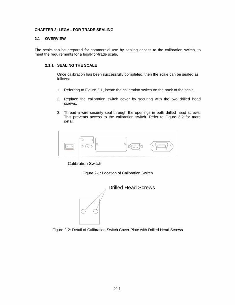
CHAPTER 2: LEGAL FOR TRADE SEALING
2.1 OVERVIEW
The scale can be prepared for commercial use by sealing access to the calibration switch, tomeet the requirements for a legal-for-trade scale.
2.1.1 SEALING THE SCALE
Once calibration has been successfully completed, then the scale can be sealed asfollows:
1. Referring to Figure 2-1, locate the calibration switch on the back of the scale.
2. Replace the calibration switch cover by securing with the two drilled headscrews.
3. Thread a wire security seal through the openings in both drilled head screws.This prevents access to the calibration switch. Refer to Figure 2-2 for moredetail.
Calibration Switch
Figure 2-1: Location of Calibration Switch
Drilled Head Screws
Figure 2-2: Detail of Calibration Switch Cover Plate with Drilled Head Screws

3-1
CHAPTER 3: GENERAL TROUBLSHOOTING FLOWCHART
START
Does
Scale Turn On
?
NO
YES
Try The Following In Order Of Appearance:
1. Replace AC Adapter.
2. Check the Display Cable.
3. Troubleshoot or Replace Main PCB.
NO
Try The Following In Order Of Appearance:
3. Replace Load Cell.
4. Replace Main PCB.
2. Check Load Cell Wiring.
Does
Scale Weigh
?
YES
NO
Try The Following In Order Of Appearance:
Do the
Keys Work
?
YES
1. Check Display Cable.
NO
Try The Following In Order Of Appearance:
1. Check for proper AC Adapter Voltage .Is the
Scale Stable
?
YES
2. Check environment.
NO
Try The Following In Order Of Appearance:
1. Check for platform obstruction (i.e. ovld stop).Is the
Scale Linear
?
YES
2. Replace load cell if zero offset count too high.
CALL
TRANSCELL
STOP
A
A
1.Try re-calibrating scale.
2. Troubleshoot or Replace Display PCB.
3. Troubleshoot or Replace Main PCB.
3. Troubleshoot or Replace Main PCB.
3. Troubleshoot or Replace Main PCB.
4-1
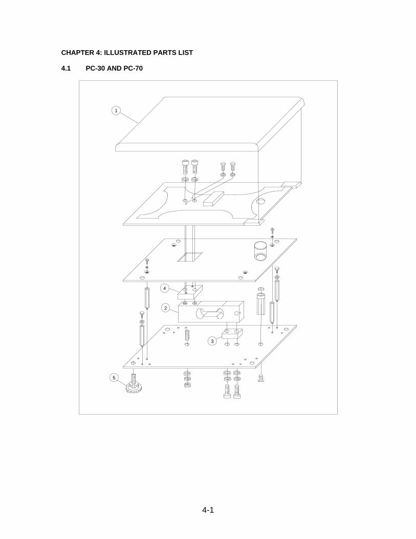
CHAPTER 4: ILLUSTRATED PARTS LIST
4.1 PC-30 AND PC-70
1
2
4
3
5

4-2
ITEM QTY PART NO. DESCRIPTION
1 1 380190008 Stainless Steel Platform
2 1 211040020 Load Cell – FAD-20 (PC-30)
2 1 211040045 Load Cell – FAD-45 (PC-70)
3 1 380190036 Bottom Spacer - Aluminum
4 1 380190037 Top Spacer - Aluminum
5 4 380190013 Adjustable Foot
– 1 250116237 AC Adapter – 12 VDC, 500 mA
1
ITEM QTY PART NO. DESCRIPTION
1 1 215193811 Main Board Assy
– 1 215366100 Display/Key Board Assy

4-3
4.2 PC-150
5
6
7
1
3

4-4
ITEM QTY PART NO. DESCRIPTION
1 1 380190008 Stainless Steel Platform
3 1 380360001 Top Spacer - Aluminum
5 1 211040100 Load Cell – FAD-100
6 1 380360007 Bottom Spacer - Aluminum
7 4 380190013 Adjustable Foot
– 1 250116237 AC Adapter – 12 VDC, 500 mA
5-1
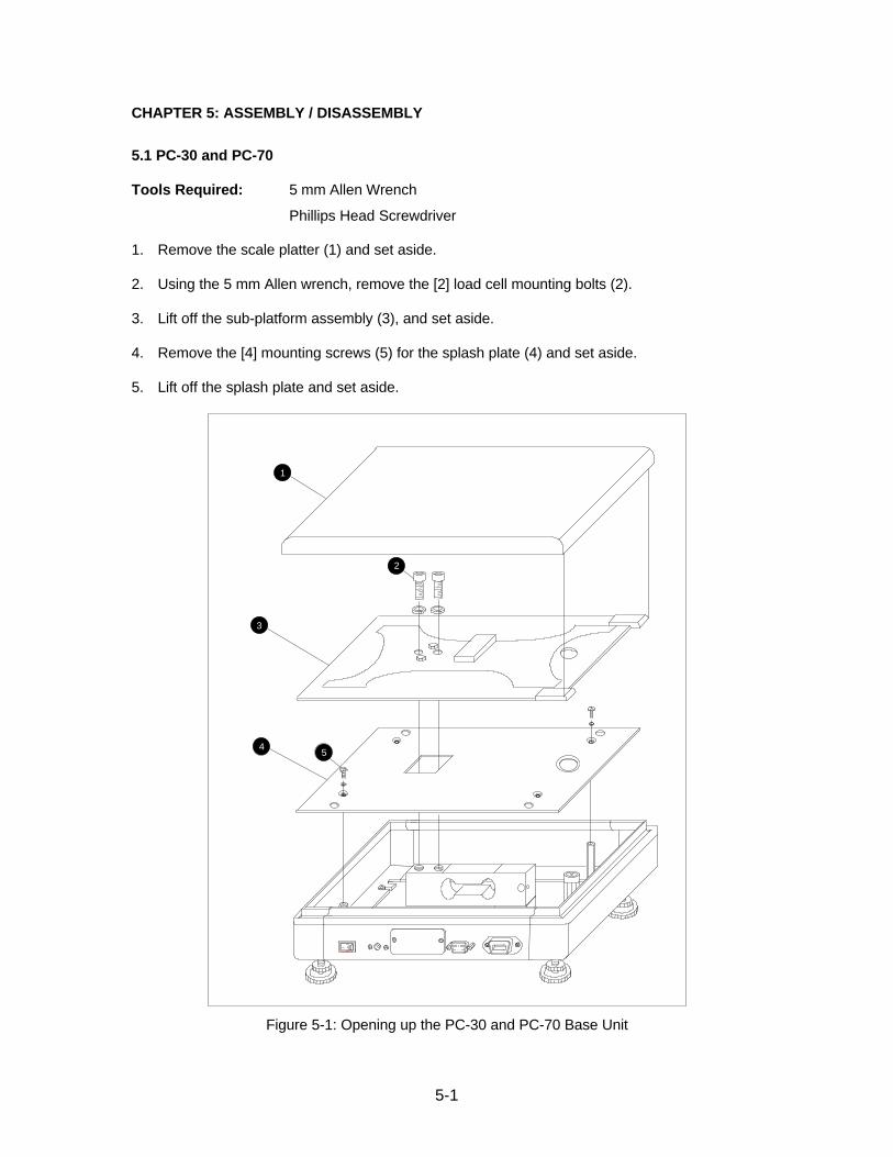
CHAPTER 5: ASSEMBLY / DISASSEMBLY
5.1 PC-30 and PC-70
Tools Required: 5 mm Allen Wrench
Phillips Head Screwdriver
1. Remove the scale platter (1) and set aside.
2. Using the 5 mm Allen wrench, remove the [2] load cell mounting bolts (2).
3. Lift off the sub-platform assembly (3), and set aside.
4. Remove the [4] mounting screws (5) for the splash plate (4) and set aside.
5. Lift off the splash plate and set aside.
1
3
4
2
5
Figure 5-1: Opening up the PC-30 and PC-70 Base Unit
5-2
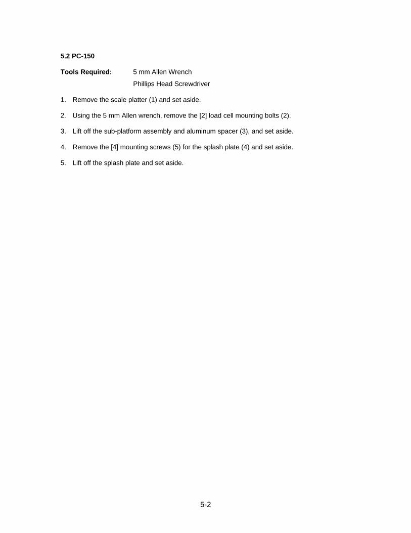
5.2 PC-150
Tools Required: 5 mm Allen Wrench
Phillips Head Screwdriver
1. Remove the scale platter (1) and set aside.
2. Using the 5 mm Allen wrench, remove the [2] load cell mounting bolts (2).
3. Lift off the sub-platform assembly and aluminum spacer (3), and set aside.
4. Remove the [4] mounting screws (5) for the splash plate (4) and set aside.
5. Lift off the splash plate and set aside.

5-3
1
2
3
4
5
Figure 5-2: Opening up the PC-150 Base Unit

CHAPTER 6: INTERNAL WIRING DIAGRAM
6-1
REDGRNBLKWHT
3
52
Load Cell
DC Power Jack
Female DSUB9JP2J1
–+
Main / ADC Board Assy
GNDSCALE RXDSCALE TXD
RED
BLKRED Setup Switch
+
On/Off Switch
1 2
+
LED
REDGRNBLKWHT
1234
E+S+E–S–
J8
21 Ferrite Bead Core
Ferrite Bead Core
J31 2 3 4
J2
Female 14-PIN CENTRONICS
TO REMOTE DISPLAY/ KEYUNIT (PC-30 &
1 2 3 4 5 6 7 8 9 10
10987654321
PC-70 ONLY)
Display/Key Board Assy (PC-150 only)
Figure 6-1: PC Series Chassis Wiring Diagram

7-1
CHAPTER 7: THEORY OF OPERATION
7.1 THEORY OF OPERATION OVERVIEW
Refer to Appendix C for reference designators.
7.1.1 MAIN / ADC BOARD ASSEMBLY
Power to the scale is supplied by a 12 VDC, 500 mA adapter. Regulator U1 supplies+5 VDC to the digital components. Regulator U8 supplies + 10 VDC to the analogcomponents including load cell excitation. Switching regulator V5 inverts the + 10VDC to – 10 VDC to act as the negative supply rail. Regulators V4 and V6 furtherregulate to ± 8 VDC for the A/D converter IC, U9.
Op-amp U11 forms a high impedance bridge amplifier for the load cell with a fixedgain of 100. Op-amp U10:B forms a low pass filter to prevent unwanted noise fromentering the circuit. The other half of U10 (U10:A) provides a buffered referencevoltage for op-amp U11. The A/D converter, U1, is a dual slope type converter.Timing is controlled by the microcontroller.
Microcontroller U2 executes several functions including A/D fetch, digital signalconditioning, key scan, serial communication, and display output. EEPROM U5contains calibration data as well as the setup parameters. IC U7 is the EPROM,which contains program memory. The network around U4 boosts the MCU’s UARTsignal to RS-232 level for serial communication with a host device.
7.1.2 DISPLAY/KEY BOARD ASSEMBLY
This circuit contains footprints for 5 keys, display driver (U4) and the LED Display(U1-U3).

A-1
APPENDIX A: TECHNICAL SPECIFICATIONS
ANALOG SPECIFICATIONS
Full Scale Input Signal 16 mV, including dead loadInternal Resolution Approximately 150,000 countsDisplayed Resolution Up to 3,500 graduations maxMeasurement Rate 10 Meas/sec, nominalSystem Linearity Within 0.02% of FSCalibration Method Software Calibration, with long term storage in EEPROMExcitation Voltage +10 VDCRFI Protection Signal lines protected by LC Low Pass Filters
Excitation & Power lines protected by EMI Chokes
DIGITAL SPECIFICATIONS
Microcontroller Intel 80C32Program Memory: 32K x 8, external to µCEEPROM: 64 x 16, external to µC
SERIAL COMMUNICATIONS
RS-232 Full Duplex, Selectable Baud, Data Bits and Parity
OPERATOR INTERFACE
Display 6-Digit, 0.56” 7-segment LED DisplayKeyboard 5-key Tactile Keypad
POWER
AC Adapter 12 VDC, 500mA
ENVIRONMENTAL
Operating Temperature 41°F (0°C) to 95°F (40° C)Storage Temperature -4°F (-20°C) to 167°F (+75°C)Operating RH 20% to 95%, non-condensingStorage RH 20% to 98%PHYSICAL DIMENSIONS:
13.0 in [330.2 mm]
4.4 in [112 mm]
ON/OFFSWITCH
DC POWERJACK
RS-232PORT
REMOTEDISPLAY
ID TAGCALIBRATIONSWITCH COVER
13.0 in [330.2 mm]
PC-150 Only
10.2 in [258.0 mm]
PC-30/70
CONNECTOR(WP-30 & 70 ONLY)
Page B-1
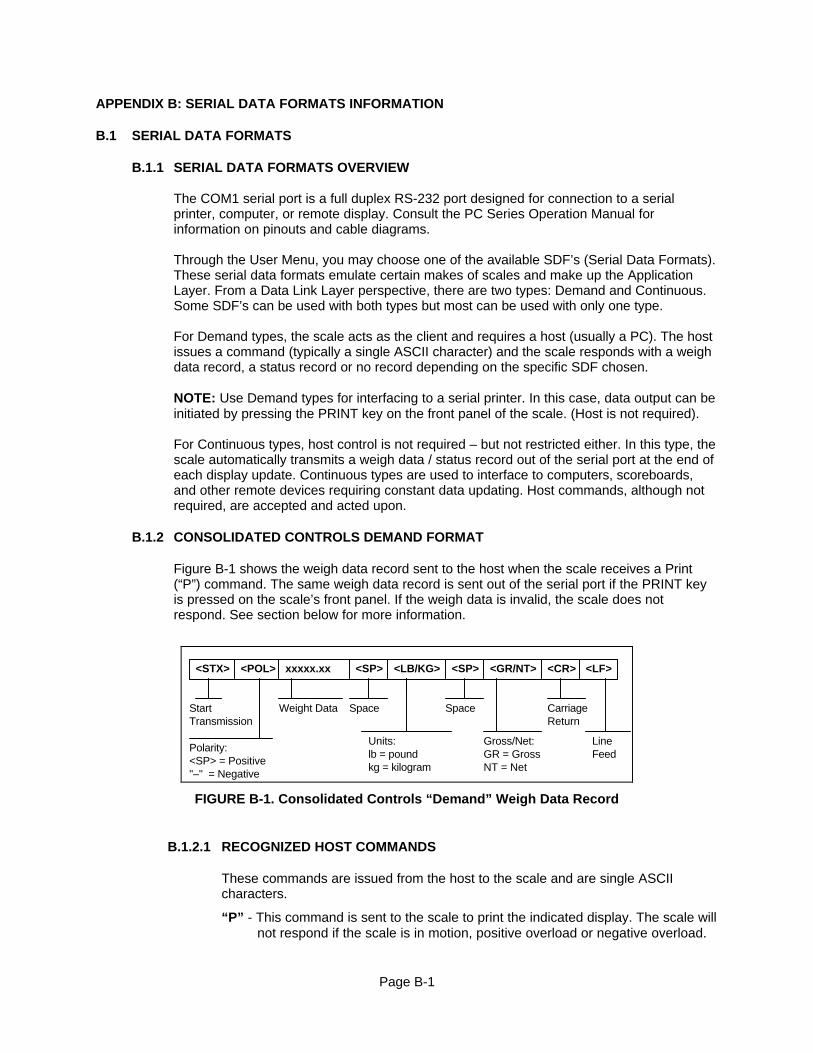
APPENDIX B: SERIAL DATA FORMATS INFORMATION
B.1 SERIAL DATA FORMATS
B.1.1 SERIAL DATA FORMATS OVERVIEW
The COM1 serial port is a full duplex RS-232 port designed for connection to a serialprinter, computer, or remote display. Consult the PC Series Operation Manual forinformation on pinouts and cable diagrams.
Through the User Menu, you may choose one of the available SDF’s (Serial Data Formats).These serial data formats emulate certain makes of scales and make up the ApplicationLayer. From a Data Link Layer perspective, there are two types: Demand and Continuous.Some SDF’s can be used with both types but most can be used with only one type.
For Demand types, the scale acts as the client and requires a host (usually a PC). The hostissues a command (typically a single ASCII character) and the scale responds with a weighdata record, a status record or no record depending on the specific SDF chosen.
NOTE: Use Demand types for interfacing to a serial printer. In this case, data output can beinitiated by pressing the PRINT key on the front panel of the scale. (Host is not required).
For Continuous types, host control is not required – but not restricted either. In this type, thescale automatically transmits a weigh data / status record out of the serial port at the end ofeach display update. Continuous types are used to interface to computers, scoreboards,and other remote devices requiring constant data updating. Host commands, although notrequired, are accepted and acted upon.
B.1.2 CONSOLIDATED CONTROLS DEMAND FORMAT
Figure B-1 shows the weigh data record sent to the host when the scale receives a Print(“P”) command. The same weigh data record is sent out of the serial port if the PRINT keyis pressed on the scale’s front panel. If the weigh data is invalid, the scale does notrespond. See section below for more information.
<STX> <POL> xxxxx.xx <LB/KG> <GR/NT> <CR> <LF>
Polarity:<SP> = Positive"–" = Negative
Weight Data
Units:lb = poundkg = kilogram
Gross/Net:GR = GrossNT = Net
StartTransmission
CarriageReturn
LineFeed
<SP> <SP>
SpaceSpace
FIGURE B-1. Consolidated Controls “Demand” Weigh Data Record
B.1.2.1 RECOGNIZED HOST COMMANDS
These commands are issued from the host to the scale and are single ASCIIcharacters.
“P” - This command is sent to the scale to print the indicated display. The scale willnot respond if the scale is in motion, positive overload or negative overload.

Page B-2
“Z” - This command is sent to the scale to zero the scale. The scale will disregardthis command if the scale is in motion, positive overload or negativeoverload. The scale will also disregard this command if it is not in gross modeor within the zero reset range. Even if successful, the host receives noresponse from the scale. The host must issue a “P” command to determine ifthe command was processed by the scale.
“T” - This command is sent to the scale to tare the scale. The scale will disregardthis command if the scale is in motion, positive overload or negativeoverload. The scale will also disregard this command if it displaying anegative gross value. Even if successful, the host receives no response fromthe scale. The host must issue a “P” command to determine if the commandwas processed by the scale.
“G” - This command is sent to the scale to revert to gross mode. The scale willdisregard this command if the scale is in motion, positive overload ornegative overload. The scale will also disregard this command if it is not innet mode. Even if successful, the host receives no response from the scale.The host must issue a “P” command to determine if the command wasprocessed by the scale.
“N” - This command is sent to the scale to revert to net. The scale will disregardthis command if the scale is in motion, positive overload or negativeoverload. The scale will also disregard this command if it is not in gross modeor a tare has yet to be established. Even if successful, the host receives noresponse from the scale. The host must issue a “P” command to determine ifthe command was processed by the scale.
“C” - This command is sent to the scale to toggle among the configured units. Evenif successful, the host receives no response from the scale. The host mustissue a “P” command to determine if the command was processed by thescale.
B.1.3 CONSOLIDATED CONTROLS CONTINUOUS FORMAT
Figure B-2 shows the weigh data / status record automatically transmitted by the scale atthe end of each display update. The same host commands listed in Section B.1.2.1 areaccepted and acted upon by the scale.
<STX> <POL> xxxxx.xx <L/K> <G/N> <STAT> <CR> <LF>
Polarity:<SP> = Positive "–" = Negative
Weight Data
Units:L = poundK = kilogram
Gross/Net:G = GrossN = Net
StartTransmission
CarriageReturn
LineFeed
Status:<SP> = ValidM = MotionO = Over/under range
FIGURE B-2. Consolidated Controls “Continuous” Weigh Data / Status Record
Page B-3
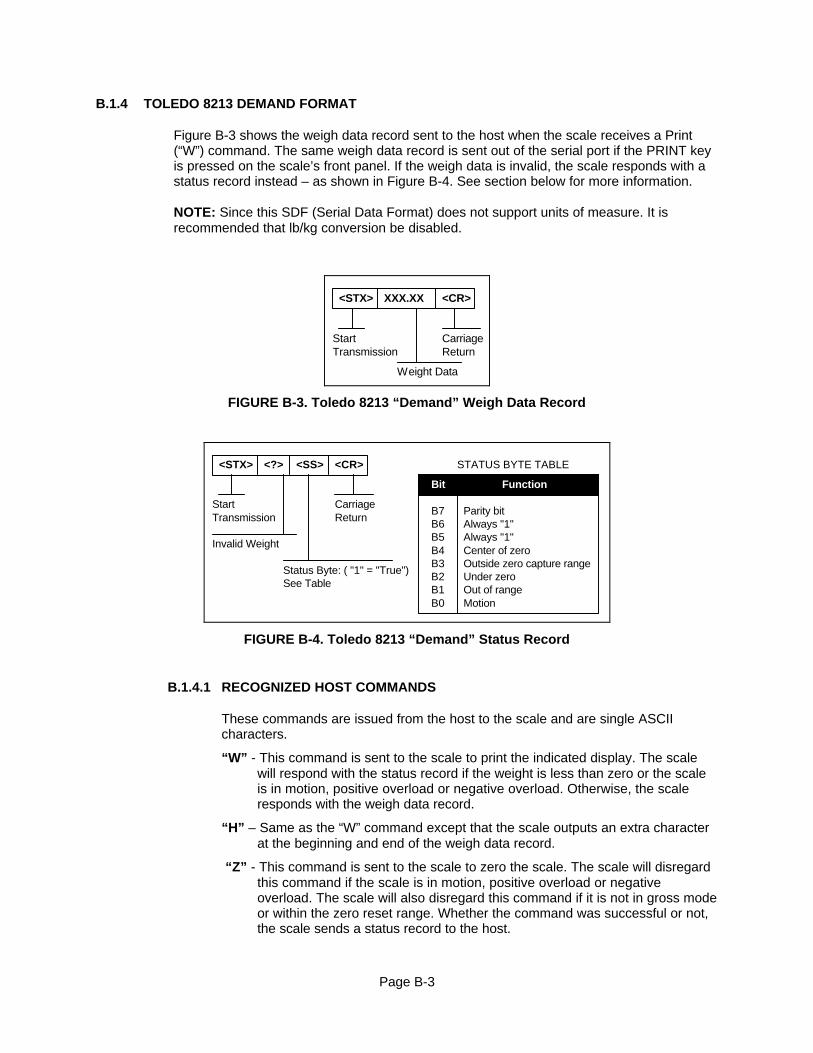
B.1.4 TOLEDO 8213 DEMAND FORMAT
Figure B-3 shows the weigh data record sent to the host when the scale receives a Print(“W”) command. The same weigh data record is sent out of the serial port if the PRINT keyis pressed on the scale’s front panel. If the weigh data is invalid, the scale responds with astatus record instead – as shown in Figure B-4. See section below for more information.
NOTE: Since this SDF (Serial Data Format) does not support units of measure. It isrecommended that lb/kg conversion be disabled.
<STX> XXX.XX <CR>
Weight Data
StartTransmission
CarriageReturn
FIGURE B-3. Toledo 8213 “Demand” Weigh Data Record
<STX> <?> <SS> <CR>
StartTransmission
CarriageReturn
Status Byte: ( "1" = "True")
Invalid Weight
B7 Parity bit
Center of zeroOutside zero capture rangeUnder zero
B6
Bit Function
Always "1"Always "1"B5
B4B3B2B1B0
Out of rangeMotion
See Table
STATUS BYTE TABLE
FIGURE B-4. Toledo 8213 “Demand” Status Record
B.1.4.1 RECOGNIZED HOST COMMANDS
These commands are issued from the host to the scale and are single ASCIIcharacters.
“W” - This command is sent to the scale to print the indicated display. The scalewill respond with the status record if the weight is less than zero or the scaleis in motion, positive overload or negative overload. Otherwise, the scaleresponds with the weigh data record.
“H” – Same as the “W” command except that the scale outputs an extra characterat the beginning and end of the weigh data record.
“Z” - This command is sent to the scale to zero the scale. The scale will disregardthis command if the scale is in motion, positive overload or negativeoverload. The scale will also disregard this command if it is not in gross modeor within the zero reset range. Whether the command was successful or not,the scale sends a status record to the host.
Page B-4
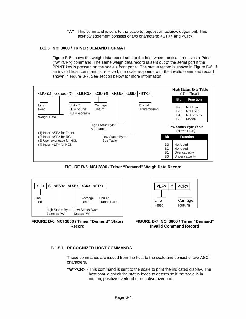
“A” - This command is sent to the scale to request an acknowledgement. Thisacknowledgement consists of two characters: <STX> and <CR>.
B.1.5 NCI 3800 / TRINER DEMAND FORMAT
Figure B-5 shows the weigh data record sent to the host when the scale receives a Print(“W”<CR>) command. The same weigh data record is sent out of the serial port if thePRINT key is pressed on the scale’s front panel. The status record is shown in Figure B-6. Ifan invalid host command is received, the scale responds with the invalid command recordshown in Figure B-7. See section below for more information.
<LF> (1) <xx.xxx> (2) <HSB>
LineFeed
High Status Byte:
Weight Data
Not UsedNot Used
Bit Function
B3B2B1B0
Not at zeroMotion
See Table
High Status Byte Table<LSB>
Low Status Byte:See Table
<CR> (4)
CarriageReturn
<ETX>
End ofTransmission
Not Used
Bit Function
B3B2B1B0
Over capacityUnder capacity
("1" = "True")
Low Status Byte Table("1" = "True")
Not Used
(1) Insert <SP> for Triner.(2) Insert <SP> for NCI.
<LB/KG>
(4) Insert <LF> for NCI.
Units (3):LB = poundKG = kilogram
(3) Use lower case for NCI.
FIGURE B-5. NCI 3800 / Triner “Demand” Weigh Data Record
<LF> <HSB>
LineFeed
High Status Byte:Same as "W"
<LSB>
Low Status Byte:See as "W"
<CR>
CarriageReturn
<ETX>
End ofTransmission
S <LF> ? <CR>
LineFeed
CarriageReturn
FIGURE B-6. NCI 3800 / Triner “Demand” StatusRecord
FIGURE B-7. NCI 3800 / Triner “Demand”Invalid Command Record
B.1.5.1 RECOGNIZED HOST COMMANDS
These commands are issued from the host to the scale and consist of two ASCIIcharacters.
“W”<CR> - This command is sent to the scale to print the indicated display. Thehost should check the status bytes to determine if the scale is inmotion, positive overload or negative overload.

Page B-5
“Z”<CR> - This command is sent to the scale to zero the scale. The scale willdisregard this command if the scale is in motion, positive overload ornegative overload. The scale will also disregard this command if it is notin gross mode or within the zero reset range. Even if successful, the hostreceives no response from the scale. The host must issue an “S”<CR>command to determine if the command was processed by the scale.
“S”<CR> - This command is sent to the scale to request the status record.
B.1.6 TRANSCELL TECHNOLOGY DEMAND FORMAT
Figure B-8 shows the weigh data record sent to the host when the scale receives a Print(“P”) command. The same weigh data record is sent out of the serial port if the PRINT keyis pressed on the scale’s front panel. If the weigh data is invalid, the scale sends the statusrecord shown in Figure B-9. See section below for more information.
<STX> <+/–> XXXX.XXX <UNITS> <GR/NT> <CR> <LF>
Polarity:+ = Positive– = Negative
Weight digits*
Units:lb = poundkg = kilogram
Gross/Net:GR = GrossNT = Net
StartTransmission
CarriageReturn
LineFeed
<SP> <SP>
SpaceSpace
* with leading zero suppression
<ETX>
EndTransmission
FIGURE B-8. Transcell Technology “Demand” Weigh Data Record
<S1> <ETX>
EndTransmission
Status Character 1:See Continuous Mode
?
QuestionMark
<S2>
Status Character 2:
<STX>
StartTransmission
See Continuous Mode
FIGURE B-9. Transcell Technology “Demand” Status Record
B.1.6.1 RECOGNIZED HOST COMMANDS
These commands are issued from the host to the scale and are single ASCIIcharacters.
“P” - This command is sent to the scale to print the indicated display. The scale willrespond with the status record instead if the scale is in motion, positiveoverload or negative overload.

Page B-6
“Z” - This command is sent to the scale to zero the scale. The scale will disregardthis command if the scale is in motion, positive overload or negativeoverload. The scale will also disregard this command if it is not in gross modeor within the zero reset range. Even if successful, the host receives noresponse from the scale. The host must issue a “P” command to determine ifthe command was processed by the scale.
“T” - This command is sent to the scale to tare the scale. The scale will disregardthis command if the scale is in motion, positive overload or negativeoverload. The scale will also disregard this command if it displaying anegative gross value. Even if successful, the host receives no response fromthe scale. The host must issue a “P” command to determine if the commandwas processed by the scale.
“G” - This command is sent to the scale to revert to gross mode. The scale willdisregard this command if the scale is in motion, positive overload ornegative overload. The scale will also disregard this command if it is not innet mode. Even if successful, the host receives no response from the scale.The host must issue a “P” command to determine if the command wasprocessed by the scale.
“N” - This command is sent to the scale to revert to net. The scale will disregardthis command if the scale is in motion, positive overload or negativeoverload. The scale will also disregard this command if it is not in gross modeor a tare has yet to be established. Even if successful, the host receives noresponse from the scale. The host must issue a “P” command to determine ifthe command was processed by the scale.
“C” - This command is sent to the scale to toggle among the configured units. Evenif successful, the host receives no response from the scale. The host mustissue a “P” command to determine if the command was processed by thescale.
B.1.7 TRANSCELL TECHNOLOGY CONTINUOUS FORMAT
Figure B-10 shows the weigh data / status record automatically transmitted by the scale atthe end of each display update. The same host commands listed in Section B.1.6.1 areaccepted and acted upon by the scale.
<+/–> XXXX.XXX <UNITS> <S1> <ETX>
Polarity:+ = Positive– = Negative
Weight Data
Units:
EndTransmission
Status Character 1:0 = valid1 = Under2 = Over
<LF>
LineFeed
<LF>
LineFeed
<S2>
Status Character 2:0 = valid1 = Motion
<STX>
StartTransmission
LB = poundsKG = kilograms
<G/N>
Gross/Net:G = GrossN = Net
2 = Zero
4 = Not Ready3 = Motion and Zero
FIGURE B-10. Transcell Technology “Continuous” Weigh Data / Status Record
Page B-7
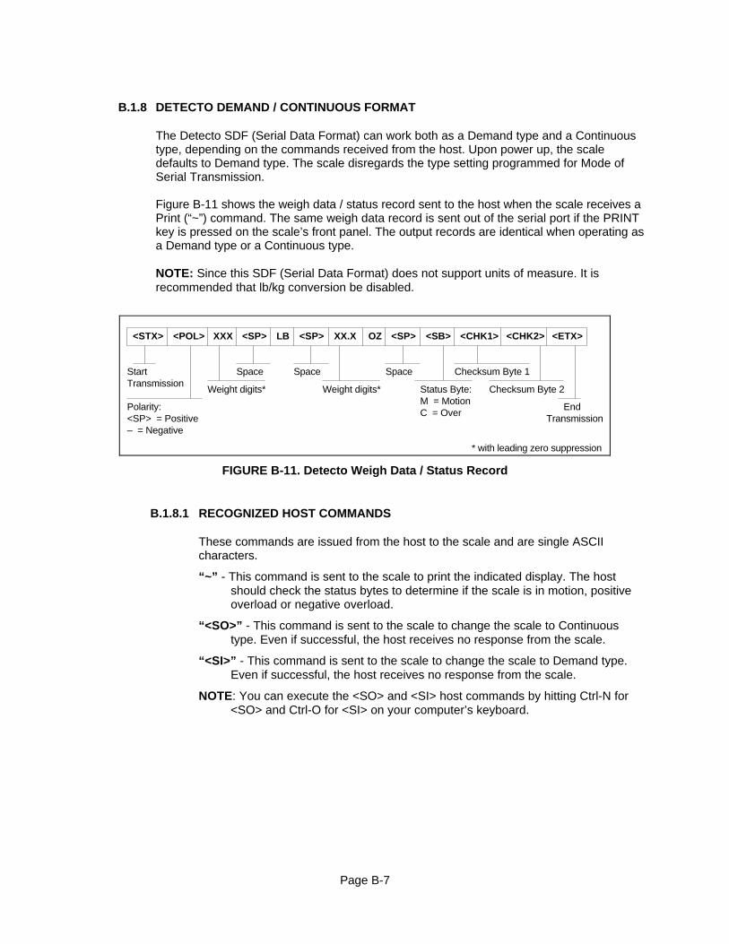
B.1.8 DETECTO DEMAND / CONTINUOUS FORMAT
The Detecto SDF (Serial Data Format) can work both as a Demand type and a Continuoustype, depending on the commands received from the host. Upon power up, the scaledefaults to Demand type. The scale disregards the type setting programmed for Mode ofSerial Transmission.
Figure B-11 shows the weigh data / status record sent to the host when the scale receives aPrint (“~”) command. The same weigh data record is sent out of the serial port if the PRINTkey is pressed on the scale’s front panel. The output records are identical when operating asa Demand type or a Continuous type.
NOTE: Since this SDF (Serial Data Format) does not support units of measure. It isrecommended that lb/kg conversion be disabled.
<STX> <POL> XXX LB <SB>
Polarity:<SP> = Positive– = Negative
Weight digits*
StartTransmission
<SP> <SP>
SpaceSpace
* with leading zero suppression
<ETX>
EndTransmission
XX.X
Weight digits*
OZ <SP>
Status Byte: M = MotionC = Over
<CHK1> <CHK2>
Space Checksum Byte 1
Checksum Byte 2
FIGURE B-11. Detecto Weigh Data / Status Record
B.1.8.1 RECOGNIZED HOST COMMANDS
These commands are issued from the host to the scale and are single ASCIIcharacters.
“~” - This command is sent to the scale to print the indicated display. The hostshould check the status bytes to determine if the scale is in motion, positiveoverload or negative overload.
“<SO>” - This command is sent to the scale to change the scale to Continuoustype. Even if successful, the host receives no response from the scale.
“<SI>” - This command is sent to the scale to change the scale to Demand type.Even if successful, the host receives no response from the scale.
NOTE: You can execute the <SO> and <SI> host commands by hitting Ctrl-N for<SO> and Ctrl-O for <SI> on your computer’s keyboard.

Page B-8
B.1.9 FAIRBANKS 70-2453-4 DEMAND FORMAT
Figure B-12 shows the weigh data / status record sent to the host when the scale receives aPrint (<CR>) command. The same weigh data record is sent out of the serial port if thePRINT key is pressed on the scale’s front panel.
XXXX.XXX <UNITS> <GR/NT>
Weight digits*
<SP> <SP>
SpaceSpace
* with leading zero suppression
<EOT>
EndTransmission
<SP>
Two Status Bytes:
<CR> <LF>
Space Carriage
lb = poundskg = kilograms
Units:
<SP>
Space
Return
CarriageReturn
GR = gross/stablegr = gross/unstable
nt = net/unstableNT = net/stable
FIGURE B-12. Fairbanks “Demand” Weigh Data / Status Record
B.1.9.1 RECOGNIZED HOST COMMANDS
These commands are issued from the host to the scale and are single ASCIIcharacters.
“<CR>” - This command is sent to the scale to print the indicated display. Thescale will not respond if the scale is in positive overload. The host shouldcheck the status bytes to determine if the scale is in motion.
“Z” - This command is sent to the scale to zero the scale. The scale will disregardthis command if the scale is in motion, positive overload or negativeoverload. The scale will also disregard this command if it is not in gross modeor within the zero reset range. Even if successful, the host receives noresponse from the scale. The host must issue a <CR> command to determineif the command was processed by the scale.
“T” - This command is sent to the scale to tare the scale. The scale will disregardthis command if the scale is in motion, positive overload or negativeoverload. The scale will also disregard this command if it displaying anegative gross value. Even if successful, the host receives no response fromthe scale. The host must issue a <CR> command to determine if thecommand was processed by the scale.
“G” - This command is sent to the scale to revert to gross mode. The scale willdisregard this command if the scale is in motion, positive overload ornegative overload. The scale will also disregard this command if it is not innet mode. Even if successful, the host receives no response from the scale.The host must issue a <CR> command to determine if the command wasprocessed by the scale.
“N” - This command is sent to the scale to revert to net. The scale will disregardthis command if the scale is in motion, positive overload or negativeoverload. The scale will also disregard this command if it is not in gross modeor a tare has yet to be established. Even if successful, the host receives noresponse from the scale. The host must issue a <CR> command to determineif the command was processed by the scale.

Page B-9
“C” - This command is sent to the scale to toggle among the configured units. Evenif successful, the host receives no response from the scale. The host mustissue a <CR> command to determine if the command was processed by thescale.

C-1
APPENDIX C: CIRCUIT DIAGRAMS
Please see attached schematic diagram sheets.