Embed Size (px)
Citation preview

Nortel Communication Server 1000
Converging the Data Networkwith VoIP FundamentalsRelease: 6.0Document Revision: 03.12
www.nortel.com
NN43001-260.
Nortel Communication Server 1000Release: 6.0Publication: NN43001-260Document release date: 3 March 2010
Copyright © 2003-2010 Nortel Networks. All Rights Reserved.
While the information in this document is believed to be accurate and reliable, except as otherwise expresslyagreed to in writing NORTEL PROVIDES THIS DOCUMENT "AS IS" WITHOUT WARRANTY OR CONDITION OFANY KIND, EITHER EXPRESS OR IMPLIED. The information and/or products described in this document aresubject to change without notice.
Nortel, Nortel Networks, the Nortel logo, and the Globemark are trademarks of Nortel Networks.
All other trademarks are the property of their respective owners.
.

3.
ContentsNew in this Release 9Navigation 9Features 9
SIP Line Service 9Zone-based dialing plan 9Meridian Customer Defined Network Alternate Routing and Vacant Number
Routing 10Other changes 10
Revision history 10
How to get help 13Getting help from the Nortel Web site 13Getting help over the telephone from a Nortel Solutions Center 13Getting help from a specialist by using an Express Routing Code 14Getting help through a Nortel distributor or reseller 14
Introduction 15Subject 15
Note on legacy products and releases 15Applicable systems 15
System migration 16Intended audience 16Conventions 16Related information 16
Overview 19Network convergence 19Quality of Service 21Network Bandwidth Management 21
Adaptive Network Bandwidth Management 23Tandem Bandwidth Management 24Network Wide Virtual Office 24
Abbreviated Dialing 24Zones 24SIP Line Service 25
Nortel Communication Server 1000Converging the Data Network with VoIP Fundamentals
NN43001-260 03.12 3 March 2010
Copyright © 2003-2010 Nortel Networks. All Rights Reserved.
.

4
Redundancy operation 25Supported codecs 25Codec selection 26Codec payload sizes considerations 26
Zone Based Dialing plan 26New prompts and changed overlays 26
Meridian Customer Defined Network Alternate Routing and Vacant NumberRouting 27
Alternative call routing for network Bandwidth Management 29Quality of Service versus Bandwidth Management 29Security 29
Secure Transport Enhancements 29UNIStim Security with DTLS 30
Network design and implementation 30Network performance measurement and monitoring 31Available tools 32
Planning and engineering 33Quality of Service 34
QoS mechanism 34The QoS process 38WAN QoS mechanisms 41Layer 2 (Ethernet) QoS 47Layer 3 QoS 50Layer 4 (TCP/IP) classification 57Policy management 58Codec selection 58Protocols in use 59Security and QoS 60
IP network best practices 60Fallback to PSTN 61Best IP network engineering practices for IP Telephony 62Considerations for using IP Trunk to achieve QoS fallback to PSTN 62Alternate circuit:switched routing 63
Bandwidth Management 70VoIP Bandwidth Management zones 70Nodal Bandwidth Management 74VPNI and Zone numbers 74Relationship between zones and subnets 76Adaptive Network Bandwidth Management 76VoIP network voice engineering considerations 82Tandem Bandwidth Management 87Codec negotiation 88
Bandwidth Management parameters 94
Nortel Communication Server 1000Converging the Data Network with VoIP Fundamentals
NN43001-260 03.12 3 March 2010
Copyright © 2003-2010 Nortel Networks. All Rights Reserved.
.

5
Zones 95Zone:based digit manipulation 98CLID composition 99CLID verification 100Vacant Number Routing 100Time of Day 101MG 1000B IP Phone calls to a local PSTN 101Emergency Services 101LAN/WAN bandwidth requirements 102Dialing plan 107Zone parameters 110
Abbreviated dialing 110Bandwidth and data network switch efficiency 112Network design assessment 112
Network modeling 112Link speeds 118Link types 119Link utilization assessment 120Traffic flows in the network 122Service level agreements 124
Network planning 124Network Performance Measurement 125
Performance criteria 125Network availability 129Media Security 129Set QoS expectations 131G.729AB codec 132G.711 codec 133G.723 codec 134Bandwidth 135Delay 148Jitter 157Packet loss 161Network delay and packet loss evaluation example 164Estimate voice quality 165
LAN design 171CS 1000 Release 6.0 configurations 171Server LAN design 178Redundant LAN design 196
Zone Based Dialing plan 201Feature dependencies and restrictions 202Overlay 10, 11 202Overlay 12 202Overlay 15 202
Nortel Communication Server 1000Converging the Data Network with VoIP Fundamentals
NN43001-260 03.12 3 March 2010
Copyright © 2003-2010 Nortel Networks. All Rights Reserved.
.

6
Overlay 20 203Overlay 21 203Overlay 22 203Overlay 43 203Overlay 81 203Overlay 83 203Overlay 117 203Feature impact on planning and engineering tasks 203
Vacant Number Routing feature 204Dialing plan 204
On:net dialing plan options 205Off:net dialing plan 205Routing 206SIP/H.323 zones 206
Distributed Media Gateway 1000E 207Fax and Modem pass through 208
Modem traffic 210Sample system layout 211
DHCP configuration 217IP Phones 217Configuring the DHCP server to support full DHCP mode 219
The VoIP network operation 227Telephony Manager 227Element Manager 227Network monitoring 228Set VoIP QoS objectives 229Intranet QoS monitoring 230ITG Operational Measurements 230OM report description 231User feedback 231QoS monitoring and reporting tools 232Network Diagnostic Utilities 232Ping and traceroute 233IP Networking statistics 233Ethernet statistics 233/RUDP statistics 233Real:Time Transport Protocol statistics 233DHCP 234Voice quality monitoring 240IP Phones voice quality monitoring 241Voice quality alarms 242Configure voice quality metric thresholds 243Configure voice quality sampling (polling) 243Configure and print zone alarm notification levels 243
Nortel Communication Server 1000Converging the Data Network with VoIP Fundamentals
NN43001-260 03.12 3 March 2010
Copyright © 2003-2010 Nortel Networks. All Rights Reserved.
.

7
Network Management 245
Configuration 249Communications Server 1000 configuration for network requirements 250
Small configuration 250Quality of Service 250Bandwidth Management 251
Configuration rules 252Bandwidth Management configuration 252Maintenance commands 253Configuring a Bandwidth Management zone 255
Configuring Dialing Plan 257Configuring the dialing plan using Communication Server 1000 Element
Manager 270Testing PSTN access using an SRG or MG 1000B IP Phone 272Troubleshooting 273
Zone Based Dialing 273Overlay 15 273Configuring numbering zone and numbering zone based parameters 274
Meridian Customer Defined Network Alternate Routing and Vacant NumberRouting 276
Meridian Customer Defined Network Alternate Routing configuration 276Vacant Number Routing configuration 276
Codec configuration 276G.729 VAD negotiation via SIP 276Configuring codecs 277
Adaptive Network Bandwidth Management configuration 281Configuration rules 281Advanced configuration notes 282
Provisioning for Tandem Bandwidth Management 282Bandwidth Management support for Network Wide Virtual Office 287
Operating parameters 288Feature Packaging 288Feature Implementation 288Feature Interactions 290
Alternative call routing for Network Bandwidth Management 291Dialing plan 292Operating parameters 293Feature interactions 294Feature packaging 295ALTPrefix 296Alternative Call Routing for Network Bandwidth Management scenarios 296Feature implementation using Command Line Interface 306
Collaboration between a Communication Server 1000 Release 4.0 (or later) NRSand a Succession 3.0 H.323 Gatekeeper 307
Nortel Communication Server 1000Converging the Data Network with VoIP Fundamentals
NN43001-260 03.12 3 March 2010
Copyright © 2003-2010 Nortel Networks. All Rights Reserved.
.

8
NRS collaboration with Gatekeeper 308Configuring the MCS 5100 system as a Collaborative Server 314
Zone configuration 315Zone Basic Property and Bandwidth Management 315Adaptive Network Bandwidth Management and CAC 316Alternate Routing for Calls between IP stations 322Branch Office Dialing Plan and Access Codes 324Branch Office Time Difference and Daylight Saving Time Property 325The MG 1000B zone configuration 327Abbreviated dialing 334Print branch office zone information 338Enable/disable branch office zone features 339View status of branch office zone at main office Call Server 339Change/print Proactive Voice Quality notification levels 340Print PVQ statistics 340Diagnostics 340Maintenance 345
SIP Line service 353
Subnet mask conversion 355Subnet mask conversion from CIDR to dotted decimal format 355
Port number tables 357Ephemeral ports 358Linux considerations 358Co-resident (Linux) Call Server port numbers 377SIP Lines Gateway Port Numbers 388Unified Communications Manager Port Numbers 403
DHCP supplemental information 419Introduction to DHCP 420IP acquisition sequence 423IP Phone support for DHCP 427
Setup and configuration of DHCP servers 433Install a Windows NT 4 or Windows 2000 server 433Configure a Windows NT 4 server with DHCP 433Configure a Windows 2000 server with DHCP 436Install ISC DHCP Server 441Configure ISC DHCP Server 441Install and configure a Solaris 2 server 444
Change CS 1000 IP addresses 447
Nortel Communication Server 1000Converging the Data Network with VoIP Fundamentals
NN43001-260 03.12 3 March 2010
Copyright © 2003-2010 Nortel Networks. All Rights Reserved.
.

9.
New in this ReleaseThe following sections detail what’s new in Converging the Data Networkwith VoIP Fundamentals (NN43001-260) for Nortel Communication Server1000 Release 6.0.
Navigation• “Features” (page 9)
• “Other changes” (page 10)
FeaturesSee the following sections for information about feature changes:
• “SIP Line Service” (page 9)
• “Zone-based dialing plan” (page 9)
• “Meridian Customer Defined Network Alternate Routing and VacantNumber Routing” (page 10)
SIP Line ServiceSIP Line Service fully integrates SIP end points in Communication Server1000 and extends telephony features to SIP clients.
Zone-based dialing planThe primary objective of this feature is to replace traditional nodal PBXnetworks with a one or more high capacity soft switches and branchgateways for PSTN access.
You can also deploy the Zone Based Dialing (ZBD) plan to setup privatenetworks in multiple locations.
The migration is transparent to users, that is, the private and public (E.164)dial plans and features are retained.
Nortel Communication Server 1000Converging the Data Network with VoIP Fundamentals
NN43001-260 03.12 3 March 2010
Copyright © 2003-2010 Nortel Networks. All Rights Reserved.
.

10 New in this Release
Meridian Customer Defined Network Alternate Routing and VacantNumber Routing
This feature development combines both the Vacant Number Routing(VNR) and Meridian ALTernate (MALT) Routing functionality for callsrouted over Internet Protocol (IP), to give more benefit to the customerto route the call to a proper destination and provide appropriate vacantnumber treatment. This feature also provides flexibility to the user toconfigure predefined cause values to perform MALT through ElementManager (EM).
Other changesSee the following section for information about changes that are notfeature related:
Revision historyFebruary 2010
Standard 03.12. This document is up-issued for changes in technicalcontent. “Change CS 1000 IP addresses” (page 447) is revised to includeformatting changes.
January 2010
Standard 03.11. This document is up-issued to support NortelCommunication Server 1000 Release 6.0.
January 2010
Standard 03.10. This document is up-issued to support NortelCommunication Server 1000 Release 6.0.
June 2009
Standard 03.09. This document is up-issued to support NortelCommunication Server 1000 Release 6.0.
June 2009
Standard 03.08. This document is up-issued to support NortelCommunication Server 1000 Release 6.0.
May 2009
Standard 03.07. This document is up-issued to support NortelCommunication Server 1000 Release 6.0.
May 2009
Nortel Communication Server 1000Converging the Data Network with VoIP Fundamentals
NN43001-260 03.12 3 March 2010
Copyright © 2003-2010 Nortel Networks. All Rights Reserved.
.

Other changes 11
Standard 03.06. This document is up-issued to support NortelCommunication Server 1000 Release 6.0.
July 2008 Standard 02.04. This document is up-issued to address a CR.
July 2008 Standard 02.03. This document is up-issued to consolidateNetwork Bandwidth Management content for Communication Server 1000Release 5.5. A screen capture for the Edit window in Element Managerwas also updated to address a CR.
February 2008 Standard 02.02. This document is up-issued for changesin technical content. References to non-supported systems are removedand updated screen captures are added for release 5.5.
December 2007 Standard 02.01. This document is up:issued tosupport Nortel Communication Server 1000 Release 5.5. References tonon:supported systems are removed and updated screen captures areadded for release 5.5.
January 2008 Standard 01.05. This document is up:issued for changes intechnical content, including new images and revised port number tables.
November 2007 Standard 1.04. This document is up:issued to reflectchanges in the QoS alarms that are listed in Table 51 "Voice qualitythreshold alarm notification levels" (page 244).
September 2007 Standard 01.03. This document is up:issued to addMedia Gateway Controller (MGC) technical content and to removereferences to systems not supported in release 5.0.
June 2007 Standard 01.02. This document is up:issued to reflectchanges in technical content for CR Q01669176. A note regarding SecureReal:Time Transport Protocol (SRTP) bandwidth considerations is addedto the section.
May 2007 Standard 01.01. This document is issued to support NortelCommunication Server 1000 Release 5.0. This document is renamedConverging the Data Network with VoIP Fundamentals (NN43001:260)and contains information previously contained in the following legacydocument, now retired: Converging the Data Network with VoIP(553:3001:160).
November 2006 Standard 6.00. This document is up:issued for CRQ01456113, adding explanations and examples of graphical and text XASconfiguration strings.
Nortel Communication Server 1000Converging the Data Network with VoIP Fundamentals
NN43001-260 03.12 3 March 2010
Copyright © 2003-2010 Nortel Networks. All Rights Reserved.
.
12 New in this Release
July 2006 Standard 5.00. This document is up:issued for changes intechnical content.
March 2006 Standard 4.00. This document is up:issued for CR Q0128628,clarifying Network Diagnostic Utilities CLI commands.
August 2005 Standard 3.00. This document is up:issued to supportCommunication Server 1000 Release 4.5.
September 2004 Standard 2.00. This document is up:issued forCommunication Server 1000 Release 4.0.
October 2003 Standard 1.00. This document is a new NTP for Succession3.0. It was created to support a restructuring of the DocumentationLibrary. This document contains information previously contained in thefollowing legacy document, now retired: Data Networking Guidelines(553:3023:103).
Nortel Communication Server 1000Converging the Data Network with VoIP Fundamentals
NN43001-260 03.12 3 March 2010
Copyright © 2003-2010 Nortel Networks. All Rights Reserved.
.

13.
How to get helpThis chapter explains how to get help for Nortel products and services.
Getting help from the Nortel Web site
The best way to get technical support for Nortel products is from the NortelTechnical Support Web site: www.nortel.com/support
This site provides quick access to software, documentation, bulletins, andtools to address issues with Nortel products. From this site, you can:
• download software, documentation, and product bulletins
• search the Technical Support Web site and the Nortel Knowledge Basefor answers to technical issues
• sign up for automatic notification of new software and documentationfor Nortel equipment
• open and manage technical support cases
Getting help over the telephone from a Nortel Solutions Center
If you do not find the information you require on the Nortel TechnicalSupport Web site, and you have a Nortel support contract, you can alsoget help over the telephone from a Nortel Solutions Center.
In North America, call 1:800:4NORTEL (1:800:466:7835).
Outside North America, go to the following Web site to obtain thetelephone number for your region:
www.nortel.com/callus
Nortel Communication Server 1000Converging the Data Network with VoIP Fundamentals
NN43001-260 03.12 3 March 2010
Copyright © 2003-2010 Nortel Networks. All Rights Reserved.
.

14 How to get help
Getting help from a specialist by using an Express Routing Code
To access some Nortel Technical Solutions Centers, you can use anExpress Routing Code (ERC) to quickly route your call to a specialist inyour Nortel product or service. To locate the ERC for your product orservice, go to:
www.nortel.com/erc
Getting help through a Nortel distributor or reseller
If you purchased a service contract for your Nortel product from adistributor or authorized reseller, contact the technical support staff for thatdistributor or reseller.
Nortel Communication Server 1000Converging the Data Network with VoIP Fundamentals
NN43001-260 03.12 3 March 2010
Copyright © 2003-2010 Nortel Networks. All Rights Reserved.
.

15.
IntroductionThis document contains the following topics:
Navigation• “Overview” (page 19)
• “Planning and engineering” (page 33)
• “Configuration” (page 249)
• “Subnet mask conversion” (page 355)
• “Port number tables” (page 357)
• “DHCP supplemental information” (page 419)
• “Setup and configuration of DHCP servers” (page 433)
SubjectThis document describes the elements and processes necessary to build aconverged multimedia network with Nortel Communications Server 1000.
Note on legacy products and releasesThis NTP contains information about systems, components, and featuresthat are compatible with Nortel Communication Server 1000 Release 6.0(or later) software. For more information about legacy products andreleases, click the Technical Documentation link under Support &Training on the Nortel home page:
www.nortel.com
Applicable systemsThis document applies to the following systems:
• Communication Server 1000M Single Group (CS 1000M SG)
• Communication Server 1000M Multi Group (CS 1000M MG)
• Communication Server 1000E (CS 1000E)
Nortel Communication Server 1000Converging the Data Network with VoIP Fundamentals
NN43001-260 03.12 3 March 2010
Copyright © 2003-2010 Nortel Networks. All Rights Reserved.
.

16 Introduction
• Meridian 1 PBX 61C
• Meridian 1 PBX 81C
System migrationWhen particular Meridian 1 systems are upgraded to run CommunicationServer 1000 Release 6.0 software and configured to include a SignalingServer, they become Communication Server 1000 systems.Table 1"Meridian 1 systems to CS 1000 systems" (page 16) lists each Meridian 1system that supports an upgrade path to a Communication Server 1000system.
Table 1Meridian 1 systems to CS 1000 systems
This Meridian 1 system Maps to Communication Server 1000 system
Meridian 1 PBX 11C Chassis Communication Server 1000E
Meridian 1 PBX 11C Cabinet Communication Server 1000E
Meridian 1 PBX 61C Communication Server 1000M Single Group
Meridian 1 PBX 81C Communication Server 1000M Multi Group
For more information, see Communication Server 1000M and Meridian 1Large System Upgrades Overview (NN43021-458), Communication Server1000E Upgrades (NN43041-458), and Communication Server 1000EUpgrade — Hardware Upgrade Procedures (NN43041:464).
Intended audienceThis document is intended for individuals responsible for administeringCommunication Server 1000 and Meridian 1 systems.
ConventionsTerminology
TerminologyIn this document, the following systems are referred to generically assystem:
• Communication Server 1000E (CS 1000E)
• Communication Server 1000M (CS 1000M)
• Meridian 1
Unless specifically stated otherwise, the term Element Manager refers tothe Communication Server 1000 Element Manager.
Related informationThis section lists information sources that are relevant to this document.
Nortel Communication Server 1000Converging the Data Network with VoIP Fundamentals
NN43001-260 03.12 3 March 2010
Copyright © 2003-2010 Nortel Networks. All Rights Reserved.
.

Related information 17
Technical documentsThis document references the following technical documents:
• Features and Services Fundamentals (NN43001:106)
• Unified Communications Management Common ServicesFundamentals (NN43001:116)
• IP Peer Networking Installation and Commissioning (NN43001:313)
• Linux Platform Base and Applications Installation and Commissioning(NN43001:315)
• Hospitality Features Fundamentals (NN43001:553)
OnlineTo access Nortel documentation online, click the TechnicalDocumentation link under Support & Training on the Nortel home page:
www.nortel.com
CD:ROMTo obtain Nortel documentation on CD:ROM, contact your Nortel customerrepresentative.
Nortel Communication Server 1000Converging the Data Network with VoIP Fundamentals
NN43001-260 03.12 3 March 2010
Copyright © 2003-2010 Nortel Networks. All Rights Reserved.
.

18 Introduction
Nortel Communication Server 1000Converging the Data Network with VoIP Fundamentals
NN43001-260 03.12 3 March 2010
Copyright © 2003-2010 Nortel Networks. All Rights Reserved.
.

19.
OverviewThis chapter provides a brief technical description of all the componentsassociated with converging the data and voice network.
Navigation• “Network convergence” (page 19)
• “Quality of Service” (page 21)
• “Network Bandwidth Management” (page 21)
• “Abbreviated Dialing” (page 24)
• “Zones” (page 24)
• “SIP Line Service” (page 25)
• “Zone Based Dialing plan” (page 26)
• “Meridian Customer Defined Network Alternate Routing and VacantNumber Routing ” (page 27)
• “Alternative call routing for network Bandwidth Management” (page 29)
• “Quality of Service versus Bandwidth Management” (page 29)
• “Security” (page 29)
• “Network design and implementation” (page 30)
• “Network performance measurement and monitoring” (page 31)
• “Available tools” (page 32)
Network convergenceNetwork convergence transports all services over the same networkstructure. Previously, different types of applications used separatededicated networks, such as voice, video, and data. Today, you canmerge many of these applications into a single network to reduceoperating costs and to increase ease of operation.
Nortel Communication Server 1000Converging the Data Network with VoIP Fundamentals
NN43001-260 03.12 3 March 2010
Copyright © 2003-2010 Nortel Networks. All Rights Reserved.
.

20 Overview
A traditional enterprise can have the following network types:
• private Time Division Multiplexing (TDM):based voice network
• IP network to the Internet
• Integrated Services Digital Network (ISDN) for video conferencing
• Systems Network Architecture (SNA) an IBM computer networkarchitecture
• multiprotocol network, including varied protocol types, such asInternetwork Packet Exchange (IPX)
Many enterprises use converged networks to achieve cost and operationalefficiency. A converged network mixes different types of traffic, each withvarious requirements, that creates difficulties that you must address. Whenapplications have dedicated networks, Quality of Service (QoS) technologyplays a small role. Dedicated network traffic is similar in behavior, and thenetworks are fine:tuned to achieve the required application behavior.
For example, the expectation for interactive voice is low packet loss anda minimal, fixed amount of delay. Data is sent in a steady stream, withsamples transmitted at fixed time intervals. This performance is obtainedon a circuit:switched network. A best:effort data network includes varyingamounts of packet loss and variable delay usually caused by networkcongestion. A packet:based data network usually has the oppositerequirements of a voice application.
Implementing QoS mechanisms can address the issue described above.
Voice applicationsVoice applications originate on Public Switched Telephone Networks(PSTNs) and use circuit switching in the form of Time Division Multiplexing(TDM).
TDM is engineered with very specific, predetermined behaviors tosupport real:time voice conversations. On a TDM network, bandwidth isguaranteed available for any voice call; therefore voice traffic experiencesa low, fixed amount of delay with essentially no loss.
IP networks do not guarantee available bandwidth for voice calls unlessQoS mechanisms are used to restrict delay and data loss to maintainacceptable user quality.
Nortel Communication Server 1000Converging the Data Network with VoIP Fundamentals
NN43001-260 03.12 3 March 2010
Copyright © 2003-2010 Nortel Networks. All Rights Reserved.
.

Network Bandwidth Management 21
If a voice application is sent over a best:effort IP network, the followingcan occur:
• Voice packets experience variable, unpredictable amounts of delay.
• Voice packets drop when the network becomes congested.
• Tthe network can reorder voice packets if the packets arrive out ofsequence.
You can apply QoS techniques to properly:engineered networks to supportVoIP with acceptable, consistent, and predictable voice quality.
Quality of ServiceIP networks are inherently best:effort networks. They treat all packets inthe same manner. A best:effort network has no specified parameters. Itdoes not guarantee how fast data transmits over a network, and has noassurances that the data is delivered.
Quality of Service (QoS) mechanisms guarantee that the network treatscertain packets in a specified manner.
QoS mechanisms refer to packet tagging mechanisms and networkarchitecture decisions on the TCP/IP network to expedite packetforwarding and delivery.
QoS is especially important for low:speed links, where the usual amountof available bandwidth is only several hundred kbit/s. For example, datatraffic could easily use all of the bandwidth available on a link, therebycausing voice quality problems. QoS mechanisms can guarantee thatnetwork bandwidth remains available for voice traffic.
End:to:end QoS is required for IP Telephony applications to achieve goodvoice quality and is achieved by ensuring that the different parts of thenetwork apply consistent treatment to the telephony packets.
Many of the available QoS mechanisms are described in “QoSmechanism” (page 34).
Network Bandwidth ManagementCommunication Server 1000 supports Network Bandwidth Managementon a network:wide basis, so that voice quality can be managed betweenmultiple Call Servers.
Nortel Communication Server 1000Converging the Data Network with VoIP Fundamentals
NN43001-260 03.12 3 March 2010
Copyright © 2003-2010 Nortel Networks. All Rights Reserved.
.

22 Overview
With the Network Bandwidth Management feature, you can configurebandwidth zones on a network basis, so that codec selection andbandwidth allocation software can identify whether Internet Telephones orgateways are physically collocated (in the same bandwidth zone) eventhough controlled by different Call Servers.
Adaptive Network Bandwidth Management is an enhancement ofBandwidth Management in which Quality of Service (QoS) metricsautomatically lower available bandwidth.
Bandwidth management provides a means of controlling the amount ofVoice over IP (VoIP) traffic in an IP network. Call Servers in the networkkeep track of the various amounts of VoIP traffic and provide treatment toVoIP calls. Treatment may consist of blocking new calls (Call AdmissionControl) or rerouting them if the required bandwidth is not available. Forexample, when a caller attempts to make a VoIP call and the networkreaches bandwidth limit, the system blocks or reroutes the call.
Bandwidth Management also allows for a particular codec to be selecteddepending on the type of call — a local call within the Local Area Network(LAN) or a remote call across a Wide Area Network (WAN).
Bandwidth Management is considered a QoS mechanism because itprovides a means of guaranteeing that VoIP traffic does not use morenetwork bandwidth than available.
Bandwidth Management Zones simplify VoIP network voice engineering.Bandwidth Management Zones allow an administrator to simply enter theamount of bandwidth available for voice on the IP network, instead ofdetailed voice CCS calculations across a particular link.
For example, if you use a CCS:type approach to VoIP network voiceengineering, an administrator must calculate the maximum CCS expectedbetween sites A to B, A to C, and B to C, and subsequently engineer thenetwork to support the required call volume.
Alternatively, through the use of Bandwidth Management Zones, anadministrator can enter the amount of bandwidth available for voice on theIP network into the Call Server. The amount of bandwidth is ensured usingother QoS mechanisms, such as priority and the type of voice codec used.The Call Server ensures that the VoIP call volume entering or leaving azone does not exceed the IP network available bandwidth. This enablesusers to avoid quality degradation because of insufficient bandwidth foractive connections.
Nortel Communication Server 1000Converging the Data Network with VoIP Fundamentals
NN43001-260 03.12 3 March 2010
Copyright © 2003-2010 Nortel Networks. All Rights Reserved.
.

Network Bandwidth Management 23
Call admission control applies to a single distributed system withcentralized call control, or multiple systems, such as a main site withnumerous branch offices connected with VoIP.
The following figure shows an example of Bandwidth Management.
Figure 1Bandwidth management example
ATTENTIONAfter all bandwidth is used, the system blocks and reroutes additional calls.Keep this in mind when you design and implement Network BandwidthManagement.
Adaptive Network Bandwidth ManagementAdaptive Network Bandwidth Management applies only to Interzone traffic.Adaptive Bandwidth Management builds on Bandwidth Management butadds the following functionalities:
• Adaptive Bandwidth Management automatically changes the bandwidthlimit depending on the Quality of Service (QoS) in the network.
• Bandwidth limit automatically adjusts on a zone:to:zone basis. If thereare QoS problems reported between a Call Server in Zone 3 andanother in Zone 5, then the bandwidth limit reduces for calls betweenZone 3 and Zone 5.
Nortel Communication Server 1000Converging the Data Network with VoIP Fundamentals
NN43001-260 03.12 3 March 2010
Copyright © 2003-2010 Nortel Networks. All Rights Reserved.
.

24 Overview
For more information about configuring Adaptive Network BandwidthManagement, see “Adaptive Network Bandwidth Managementconfiguration” (page 281).
Tandem Bandwidth ManagementFor the main office to correctly monitor all the bandwidth used to and froma branch office the call must tandem through the main office. When callstandem through the main office, only the signaling is tandemed, the actualvoice bandwidth travels directly between the source and destination. Formore information about provisioning for Tandem Bandwidth Management,see “Provisioning for Tandem Bandwidth Management ” (page 282).
Network Wide Virtual OfficeBandwidth Management support for Network Wide Virtual Office allows forthe correct bandwidth calculation for IP users who are using the VirtualOffice feature to login to their home IP Phones from different Call Serverswithin the network. Two fields are used to achieve this—Configured Zoneand Current Zone.
The same Virtual Private Network Identifier (VPNI) to all Call Servers in anetwork is assigned, so you can identify the entire network by one VPNInumber. You can assign the same Bandwidth zone number to differentCall Servers and an INTRAZONE policy between them.
The Network Wide Virtual Office feature does not interfere with theexisting functionality of the Bandwidth Management feature, because itsupports previous bandwidth configuration rules. This feature extendsthe meaning of the Virtual Private Network Identifier (VPNI). In previousreleases, VPNI was used to identify one customer system that consisted ofa Main Office (MO) switch and a branch office (BO) switch. Now a VPNInumber identifies the whole customer network that includes all MO and BOswitches. For more information about Bandwidth Management supportfor Network Wide Virtual Office, see “Bandwidth Management support forNetwork Wide Virtual Office” (page 287).
Abbreviated DialingWith Abbreviated Dialing, IP Phone users in the same geographic location,either the main office or the branch office, can call one another using a DNshorter than the configured DN. For more information about configuringAbbreviated Dialing, see “Abbreviated dialing” (page 334).
ZonesA zone is a collection of IP Phones that:
• share similar IP bandwidth restrictions
• exist geographically close to one another
Nortel Communication Server 1000Converging the Data Network with VoIP Fundamentals
NN43001-260 03.12 3 March 2010
Copyright © 2003-2010 Nortel Networks. All Rights Reserved.
.

SIP Line Service 25
• exist in the same time zone
• exist in the same PSTN dialing plan
Dialing plans treat all telephones in the same zone identically. You assigneach IP Phone to a zone during configuration. For more information aboutconfiguring Zones, see “Zone configuration” (page 315).
ATTENTIONThis document uses the term "zone" to refer to a Bandwidth Management Zone(not a Gatekeeper Zone).
SIP Line ServiceThe SIP Line feature comprises three major software components: CallServer (CS), SIP Line Gateway (SLG), and SMS. Software changes onCommunication Server 1000 are bundled within the SIP Line Package(417) and reside on the same hardware platform as supported in Release5.5 in addition to Linux COTS and CP PM Call Server.
ATTENTIONYou must upgrade Communication Server 1000 to Release 6.0 software toenable and configure SIP Line Service.
No upgrade is required for the SLG Service in Communication Server 1000 6.0.
For more information on upgrading to Communication Server 6.0, seeCommunication Server 1000E : Software Upgrades (NN43041:458).
Redundancy operationFor redundancy, you can configure a leader and follower for a SIP LineGateway (SLG) node with both servers sharing the same node IP.However, clients on the same node can be registered on only the currentnode master. No load sharing occurs between the two SLG nodes.
Supported codecsCodec negotiation and selection follow the same operation as SIPGateway. No new codecs are added.
In summary, support exists for the following codecs:
• G.711 u:law/a:law
• G.729A/AB
• G.723.1
• T.38 for FAX
Nortel Communication Server 1000Converging the Data Network with VoIP Fundamentals
NN43001-260 03.12 3 March 2010
Copyright © 2003-2010 Nortel Networks. All Rights Reserved.
.

26 Overview
By default, G.711 requires support at both ends of a call. The defaultpayload sizes for G.711 and G.729 are both 20 milliseconds (ms). Anyother unrecognized codec (including video) are forwarded to the far endthrough the SDP transparency feature. The SDP transparency featureenables multiple media descriptions and sends the associated codecattribute information to the destination.
Codec selectionThe SLG always sends the originating node codec list in order ofpreference, and the terminating node selects one common codec basedon preference. This means that the receiver of an offer always performsthe codec selection, and it selects one common codec based on the bestbandwidth selection mechanism.
Codec payload sizes considerationsIf the SDP has no packet time (ptime), the default payload size is used: 20ms for G.711 and G.729, and 30 ms for G.723.1.
If you configure a specific payload size different from the default payloadsize, the offer includes a ptime. Only one ptime can exist for each codec inthis version of SDP.
Zone Based Dialing planSwitching to a ZBD requires development on dial plans, numbering plansand routing features to make sure that the migration is transparent to theenterprise network users and that the same dial plan and business gradetelephony features are used.
New prompts and changed overlaysNumbering zone and zone based flexible dial plan concepts are introducedto provide ZBD functionality.
Numbering zones are assigned to all sets and attendant, and they containzone specific information such as site prefix, country code, access prefixes(for international, national, subscriber calls).
Zone based Flexible Dialing Plan (ZFDP) is introduced to reducecomplexity of configuration.
The following prompts are introduced:
• Overlay 10, 11 — New prompt NUMZONE is introduced to assign anumbering zone to a phone (analog, TDM, IP).
• Overlay 12 — New prompt NUMZONE is introduced to assign anumbering zone to an attendant.
Nortel Communication Server 1000Converging the Data Network with VoIP Fundamentals
NN43001-260 03.12 3 March 2010
Copyright © 2003-2010 Nortel Networks. All Rights Reserved.
.

Meridian Customer Defined Network Alternate Routing and Vacant Number Routing 27
• Overlay 15 — New prompt ZBD is introduced to enable or disable theZBD feature.
— New prompt DIALPLAN is introduced to show DN/CLID for privateand public on-net dial plans.
• Overlay 20 — New prompt NUMZONE is introduced to display anumbering zone configured for a set (analog, TDM, IP) or attendant.
• Overlay 21 — New prompt ZBD is introduced to display the value ofZBD option.
New prompt DIALPLAN is introduced to show configured value incustomer data block.
• Overlay 22 — ZBD package is printed.
• Overlay 43 — ZBD databases are dumped into /u/db/ during EDD.
— ZBD databases are restored from /u/db/ during database restore.
• Overlay 81 — New prompt NZON is introduced to print a list or countof telephones with selected numbering zone.
• Overlay 83 — New prompt NUMZONE is introduced to print a list ofunits with configured numbering zone.
• Overlay 117 — New commands are introduced to configure numberingzones, parameters for numbering zones (prefix, DAPC, CC, NPA, andACx) , and a zone:dialing plan.
Meridian Customer Defined Network Alternate Routing and VacantNumber Routing
Vacant Number Routing (VNR) is a default route used for routinguntranslatable, invalid, and unassigned dialed numbers (DNs). Whenthe call is routed by VNR to the IP network, the user has the flexibility toperform Meridian Customer Defined Network Alternate Routing (MALT)on the Call Server for an additional 10 causes other than the existing six.Configure these additional MALT causes within Element Manager (EM).If the call is determined to be a VNR call, which is tried at least once toroute over an IP route, then vacant number treatment is provided to thecall. Thus, this feature development combines both the VNR and MALTfunctionality for calls routed over IP, to give more benefit to the customer,by routing a call to the proper destination and providing appropriatevacant number treatment. For more information about configuring VNRand MALT, see IP Peer Networking Installation and Commissioning(NN43001-313). For more information about Element Manager, seeElement Manager: System Administration (NN43001-632).
Nortel Communication Server 1000Converging the Data Network with VoIP Fundamentals
NN43001-260 03.12 3 March 2010
Copyright © 2003-2010 Nortel Networks. All Rights Reserved.
.

28 Overview
Calls to the IP network need the ability to reroute to another alternate,while maintaining the ability to receive vacant number treatment when thecalled destination is an unassigned number. There are two parts of thisfeature:
1. MALT on calls routed to the IP domain
This feature deals with VNR calls at the CS1K, routed over H.323/SIP.If the call fails to route to the destination the call gets disconnectedwith a cause which matches one of the original MALT cause codes,or disconnects with an indication to use MCDN Alternate Routing. IfMALT exhausts all routes in the VNR route list block hen the treatmentcorresponding to the disconnect cause is provided.
With the default MALT handling, there are six causes, which performMALT at the Communication Server 1000:
— 3 : No route to destination
— 27 : Destination is out of service
— 34 : No circuit or channel available
— 38 : Network out of service
— 41 : Temporary failure
— 42 : Switching equipment congestion
2. Configurable MALT causes for different vendors
A configurable option is provided in EM for the different vendors inorder to configure causes to accomplish MALT at the CommunicationServer 1000. Element Manager provides the following causes to beconfigured to perform MALT:
— 01 – unassigned number
— 20 – subscriber absent
— 47 – Resources unavailable
— 51: Call rejected; blocked by MBG
— 52: Outgoing call barred
— 53: Outgoing call barred in closed user group
— 54: Incoming call barred
— 55: Incoming call barred in closed user group
— 63: service or option not available
— 127: Interworking unspecified
If a call disconnects prior to establishing a clear message, using oneof the causes listed previously, and the causes are configured on theSignaling Server to perform MALT, then a new IP IE is built with anindication use MALT with the cause. This IE is sent to CS with the in
Nortel Communication Server 1000Converging the Data Network with VoIP Fundamentals
NN43001-260 03.12 3 March 2010
Copyright © 2003-2010 Nortel Networks. All Rights Reserved.
.

Security 29
the received clearing message. The CS would trigger MALT forthe cause.
For more information about system messages for VNR and MALT, seeSoftware Input Output Reference - System Messages (NN43001-712)
Alternative call routing for network Bandwidth ManagementAlternative Call Routing for Network Bandwidth Management allows astation:to:station call (a call that does not use a trunk) between a branchoffice and main office to overflow to traditional routes. Overflow can occurif there is insufficient interzone bandwidth available to carry the call or ifthe Quality of Service (QoS) has degraded to unacceptable levels. Thisfeature also applies to station:to:station calls from one branch office toanother branch office, provided both stations are registered to the samemain office. For more information about Alternative Call Routing, see“Alternative call routing for Network Bandwidth Management” (page 291).
Quality of Service versus Bandwidth ManagementOne approach to network engineering states that Quality of Service (QoS)is not needed; simply increasing bandwidth provides enough QoS for allapplications. This theory also states that implementing QoS is complicatedand adding bandwidth is easy. However, due to the bursty nature of IPnetwork traffic, even very large amounts of bandwidth may not be enoughto prevent congestion during a burst of traffic at a particular instance intime.
If all networks had infinite bandwidth available, so that network congestionnever occurred, QoS technology would not be needed. While havingadequate bandwidth provisioned on the network is very important, overprovisioning may not be very realistic; therefore, QoS mechanismsare needed. For more information about QoS mechanisms, see “QoSmechanism” (page 34).
SecurityFor more information about CS1000E and CS1000M system security, seeSecurity Management Fundamentals (NN43001:604).
Secure Transport EnhancementsThis feature enhances the security of the File Transfer Protocol (FTP)infrastructure in Communication Server 1000.
Nortel Communication Server 1000Converging the Data Network with VoIP Fundamentals
NN43001-260 03.12 3 March 2010
Copyright © 2003-2010 Nortel Networks. All Rights Reserved.
.
30 Overview
SSH File Transport ProtocolSSH File Transport Protocol (SFTP) is a network protocol that providesconfidentiality and integrity to the data (such as files or commands)transmitted between an SFTP client and a server. In addition, SFTP allowsa client and a server to authenticate each other. In this feature, passwordis used by an SFTP server to authenticate an SFTP client.
UNIStim Security with DTLSUNIStim Security with DTLS provides signaling encryption for UNIStim IPPhones based on the industry standard DTLS protocol (RFC 4347).
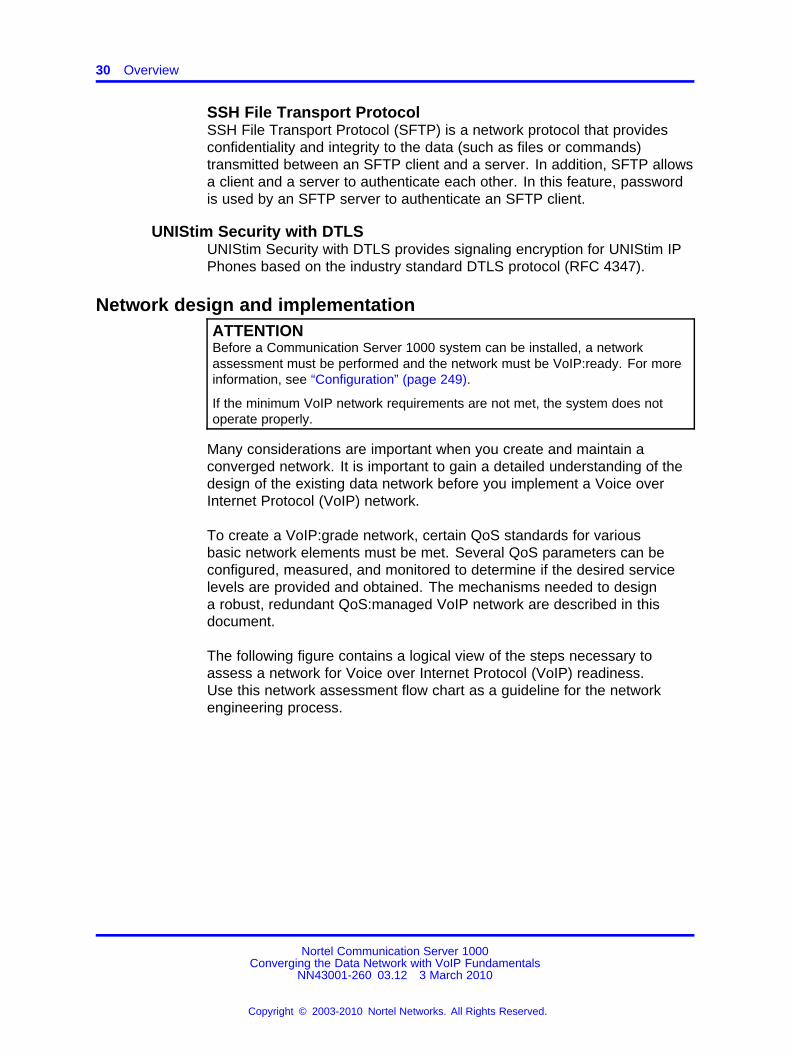
Network design and implementationATTENTIONBefore a Communication Server 1000 system can be installed, a networkassessment must be performed and the network must be VoIP:ready. For moreinformation, see “Configuration” (page 249).
If the minimum VoIP network requirements are not met, the system does notoperate properly.
Many considerations are important when you create and maintain aconverged network. It is important to gain a detailed understanding of thedesign of the existing data network before you implement a Voice overInternet Protocol (VoIP) network.
To create a VoIP:grade network, certain QoS standards for variousbasic network elements must be met. Several QoS parameters can beconfigured, measured, and monitored to determine if the desired servicelevels are provided and obtained. The mechanisms needed to designa robust, redundant QoS:managed VoIP network are described in thisdocument.
The following figure contains a logical view of the steps necessary toassess a network for Voice over Internet Protocol (VoIP) readiness.Use this network assessment flow chart as a guideline for the networkengineering process.
Nortel Communication Server 1000Converging the Data Network with VoIP Fundamentals
NN43001-260 03.12 3 March 2010
Copyright © 2003-2010 Nortel Networks. All Rights Reserved.
.

Network performance measurement and monitoring 31
Figure 2Network assessment flow chart
Network performance measurement and monitoringTCP/IP was originally designed to reliably send a packet to its destination.Little consideration was given to the length of time it took to get there.Today, IP networks transport data from many different application types.Many of these applications require minimal delay. Delay is the length oftime needed for information to travel through a network. Significant delaycan adversely affect end:user quality; and in some cases, the applicationdoes not function at all.
Nortel Communication Server 1000Converging the Data Network with VoIP Fundamentals
NN43001-260 03.12 3 March 2010
Copyright © 2003-2010 Nortel Networks. All Rights Reserved.
.

32 Overview
Networks now carry many different types of traffic. Each traffic type hasunique requirements for the following QoS parameters:
• network availability
• bandwidth
• delay
• jitter
• packet loss
These QoS parameters apply to any IP (Internet Protocol) network thatcarries VoIP traffic, including LANs, campus:wide networks, and WANs.These QoS parameters can be measured and monitored to determine ifthey meet desired service levels. Each of these elements are discussedin detail in “Network Performance Measurement” (page 125). For moreinformation about the ongoing monitoring, management, and measurementof the network, see “The VoIP network operation” (page 227).
Available toolsATTENTIONTools are available for almost every aspect of converged network engineering.Nortel strongly recommends the use of appropriate tools when performingnetwork engineering.
Some of the available tools include:
• Multiprotocol network design assessment software. These tools cananalyze a network, highlight potential problems, and propose possiblesolutions.
• SNMP:based network management systems for network designassessment and monitoring.
• Graphical device configuration managers for almost all networkswitches can integrate into SNMP network management systems.
• Policy managers for implementing end:to:end QoS policies.
• Network performance measurement tools for monitoring network jitter,delay, and packet loss.
All of these tools can be operated from a central location on the network.Use the tools to simplify network engineering and operations, ultimatelyresulting in lower costs and higher quality services.
Nortel offers professional Network Architecture and Design services. Formore information, contact a Nortel sales representative.
Nortel Communication Server 1000Converging the Data Network with VoIP Fundamentals
NN43001-260 03.12 3 March 2010
Copyright © 2003-2010 Nortel Networks. All Rights Reserved.
.

33.
Planning and engineeringThis chapter contains information about topics to consider before youimplement a converged voice and data network.
Navigation• “Quality of Service” (page 34)
• “IP network best practices” (page 60)
• “Bandwidth Management” (page 70)
• “Bandwidth Management parameters” (page 94)
• “Abbreviated dialing” (page 110)
• “Bandwidth and data network switch efficiency” (page 112)
• “Network design assessment” (page 112)
• “Network planning” (page 124)
• “Network Performance Measurement” (page 125)
• “LAN design” (page 171)
• “Zone Based Dialing plan” (page 201)
• “Vacant Number Routing feature” (page 204)
• “Dialing plan” (page 204)
• “Distributed Media Gateway 1000E” (page 207)
• “Fax and Modem pass through” (page 208)
• “DHCP configuration” (page 217)
• “The VoIP network operation” (page 227)
• UNIStim Security with DTLS
Nortel Communication Server 1000Converging the Data Network with VoIP Fundamentals
NN43001-260 03.12 3 March 2010
Copyright © 2003-2010 Nortel Networks. All Rights Reserved.
.

34 Planning and engineering
Quality of ServiceTo ensure consistent voice quality, Quality of Service (QoS) must besupported on the platforms that transport Voice over Internet Protocol(VoIP). Consider the following list to provide QoS:
• Bandwidth Management
• packet classification
• DiffServ
• fragmentation
• traffic shaping
• queueing mechanisms provided by the platform
If appropriate QoS mechanisms are not supported by the platform, anupgrade can be required.
QoS mechanismAn IP network must be properly engineered and provisioned to achievehigh voice quality performance. The network administrator shouldimplement QoS policies network:wide, so voice packets receive consistentand proper treatment as they travel the network.
IP networks that treat all packets the same are called best:effort networks.In such a network, traffic can experience different amounts of delay, jitter,and loss at any given time. This can produce the following problems:
• speech breakup
• speech clipping
• pops and clicks
• echo
A best:effort network does not guarantee bandwidth at any given time.
The best way to guarantee bandwidth for voice applications is to use QoSmechanisms in the intranet when the intranet is carrying mixed traffictypes.
QoS mechanisms ensure bandwidth is 100% available at most times, andmaintain consistent, acceptable levels of loss, delay, and jitter, even underheavy traffic loads.
QoS mechanisms are extremely important to ensure satisfactory voicequality. If QoS mechanisms are not used, there is no guarantee that thebandwidth required for voice traffic is available. For example, a data filedownloaded from the intranet could use most of the WAN bandwidth
Nortel Communication Server 1000Converging the Data Network with VoIP Fundamentals
NN43001-260 03.12 3 March 2010
Copyright © 2003-2010 Nortel Networks. All Rights Reserved.
.

Quality of Service 35
unless voice traffic has been configured to have higher priority. If the datafile download uses most of the available bandwidth, it causes voice packetloss and; therefore, poor voice quality.
Apply QoS mechanisms to the following VoIP media and signaling paths:
• TLAN connections
• VoIP traffic between IP Phones
• VoIP traffic between IP Phones and Voice Gateway Media Cards onthe TLAN subnet
ATTENTIONNortel strongly recommends that you implement suitable QoS mechanisms onany IP network that carries VoIP traffic.
Traffic mixBefore you implement QoS mechanisms, assess the traffic mix ofthe network. QoS mechanisms depend on the process and ability todistinguish traffic by class to provide differentiated services.
If an intranet delivers only VoIP traffic, and all traffic flows are of equalpriority, you do not need to consider QoS mechanisms. This networkwould only have one class of traffic.
In most corporate environments, the intranet primarily supports dataservices. When you plan to offer voice services over the intranet, assessthe following:
• Are there existing QoS mechanisms? What are they? VoIP trafficshould take advantage of established mechanisms, if possible.
• What is the traffic mix? If the volume of VoIP traffic is small comparedto data traffic on the intranet, then IP QoS mechanisms are sufficient. IfVoIP traffic is significant, data services might be impacted when thosemechanisms are biased toward VoIP traffic.
TCP traffic behaviorThe majority of corporate intranet traffic is TCP:based. Unlike UDP, whichhas no flow control, TCP uses a sliding window flow control mechanism.Under this scheme, TCP increases its window size, increasing throughput,until congestion occurs. Congestion is detected by packet losses, andwhen that happens throughput quickly throttles down, and the whole cyclerepeats. When multiple TCP sessions flow over few bottleneck links in theintranet, the flow control algorithm can cause TCP sessions in the networkto throttle at the same time, resulting in a periodic and synchronized
Nortel Communication Server 1000Converging the Data Network with VoIP Fundamentals
NN43001-260 03.12 3 March 2010
Copyright © 2003-2010 Nortel Networks. All Rights Reserved.
.

36 Planning and engineering
surge and ebb in traffic flows. WAN links appear to be congested at oneperiod of time and then are followed by a period of under:utilization. Twoconsequences are:
• WAN link inefficiency.
• VoIP traffic streams are unfairly affected.
The solution to this problem is Weighted Random Early Detectionqueueing (WRED) as described on “Weighted Random Early Detection”(page 39) .
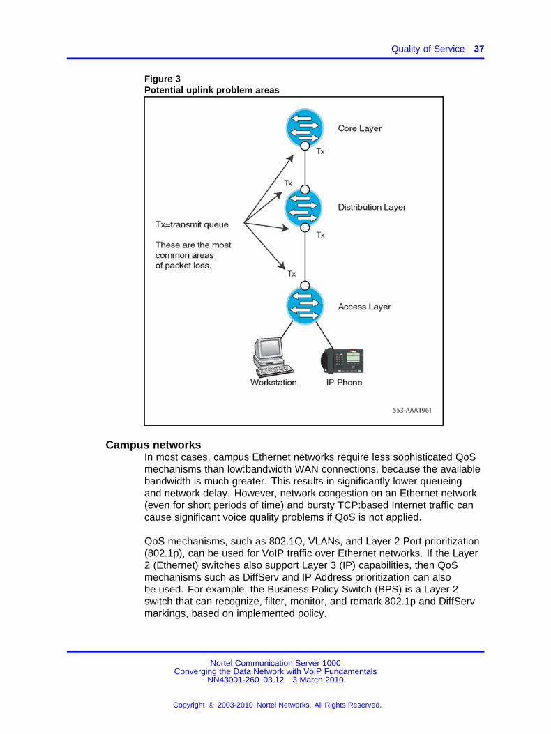
QoS problem locationsFigure 3 "Potential uplink problem areas" (page 37) identifies typicalnetwork congestion areas. Voice traffic competes for limited bandwidthon the uplinks. These uplinks are shown in Figure 3 "Potential uplinkproblem areas" (page 37). Congestion at these points causes the majorityof all packet loss, delay, and jitter. QoS mechanisms can alleviate thiscongestion by using multiple queues with different priorities.
Nortel Communication Server 1000Converging the Data Network with VoIP Fundamentals
NN43001-260 03.12 3 March 2010
Copyright © 2003-2010 Nortel Networks. All Rights Reserved.
.
Quality of Service 37
Figure 3Potential uplink problem areas
Campus networksIn most cases, campus Ethernet networks require less sophisticated QoSmechanisms than low:bandwidth WAN connections, because the availablebandwidth is much greater. This results in significantly lower queueingand network delay. However, network congestion on an Ethernet network(even for short periods of time) and bursty TCP:based Internet traffic cancause significant voice quality problems if QoS is not applied.
QoS mechanisms, such as 802.1Q, VLANs, and Layer 2 Port prioritization(802.1p), can be used for VoIP traffic over Ethernet networks. If the Layer2 (Ethernet) switches also support Layer 3 (IP) capabilities, then QoSmechanisms such as DiffServ and IP Address prioritization can alsobe used. For example, the Business Policy Switch (BPS) is a Layer 2switch that can recognize, filter, monitor, and remark 802.1p and DiffServmarkings, based on implemented policy.
Nortel Communication Server 1000Converging the Data Network with VoIP Fundamentals
NN43001-260 03.12 3 March 2010
Copyright © 2003-2010 Nortel Networks. All Rights Reserved.
.

38 Planning and engineering
Wide area networksA wide area network (WAN) is a geographically:dispersedtelecommunications network. For example, a WAN can extend acrossmany cities or countries.
WANs require more sophisticated QoS mechanisms, such asfragmentation and interleaving.
For more information, see “WAN QoS mechanisms” (page 41).
The QoS processPacket handling on a QoS:enabled network consists of three stages:
1. Classification
2. Marking
3. Queueing, also known as Forwarding
To implement QoS on an IP network, all packets entering the IP networkmust be classified and marked. The packets are then placed intotransmission queues of a certain priority.
Packets in high:priority queues are transmitted before packets inbest:effort lower priority queues. VoIP packets no longer have to competewith best:effort data packets for IP network resources. Typical QoSimplementations protect call quality by minimizing loss, delay, and jitter.Bandwidth cannot be assured without the use of some type of reservationprotocol, such as Resource Reservation Setup Protocol (RSVP).
ClassificationSoftware on the following hardware elements can classify and mark VoIPpackets:
• Signaling Server – classifies packets as signaling packets.
• Voice Gateway Media Card – classifies packets as voice or signalingpackets.
• IP Phones – classifies packets as voice or signaling packets.
ATTENTIONTo classify Signaling Server and Voice Gateway Media Card packets at Layer2 (802.1p), Layer 3 (DiffServ) or both, implement QoS mechanisms on theSignaling Server and Voice Gateway Media Card and the Layer 2 switch portsto which they are attached. IP Phones with firmware 1.31 (or later) can classifyvoice and signaling packets at Layer 2 (802.1p), Layer 3 (DiffServ), or both.
Classification can be implemented on Layer 2 or Layer 3 switches. Seethe switch documentation for information about configuring classification.
Nortel Communication Server 1000Converging the Data Network with VoIP Fundamentals
NN43001-260 03.12 3 March 2010
Copyright © 2003-2010 Nortel Networks. All Rights Reserved.
.

Quality of Service 39
Policy management also provides other methods to classify and markpackets, based on identifiers, such as the originating IP address of thepacket. For more information about Policy Management, see “Policymanagement” (page 58).
Packets can also be premarked with default 802.1p and DiffServCodePoint (DSCP) values. Configure the Layer 2, Layer 3, or Policyswitches to trust that these packets are marked correctly.
MarkingWhen powered:up, Nortel IP Phones contact the Terminal Proxy Server(TPS) that controls them. The TPS then instructs the IP Phones to mark allpackets with a default configurable (through Communication Server 1000Manager) DSCP and/or 802.1Q/802.1p tag. The tag is also configurableusing Communication Server 1000 Element Manager. The control packetsare marked for each of the following.
• Signaling Server
• Voice Gateway Media Cards
• Media Gateway 1000T (MG 1000T)
• Network Routing Service
QueueingQueueing delay is a major contributor to delay, especially on highlyused and low:bandwidth WAN links (see “Queueing delay” (page 152)). Routers that are QoS:aware and that support priority queueing canhelp reduce the queueing delay of voice packets when these packets aretreated with preference over other packets.
Weighted Random Early Detection The global synchronization situationdescribed in “TCP traffic behavior” (page 35) can be countered using abuffer management scheme that discards packets randomly as the queuestarts to exceed a threshold. Weighted Random Early Detection (WRED),an implementation of this strategy, also inspects the DiffServ bits in theIP header when considering which packets to drop during buffer build up.In an intranet environment where TCP traffic dominates real:time traffic,WRED can be used to maximize the packet dropping from long:lived TCPsessions and minimize the voice packet dropping. Check the configurationguidelines with the router vendor for performance ramifications when youenable WRED. If global synchronization is to be countered effectively,implement WRED at core and edge routers.
Packet prioritization and schedulers for VoIP All VoIP packets mustbe given a priority higher than the priority of non voice packets to minimize
Nortel Communication Server 1000Converging the Data Network with VoIP Fundamentals
NN43001-260 03.12 3 March 2010
Copyright © 2003-2010 Nortel Networks. All Rights Reserved.
.

40 Planning and engineering
delay, jitter (delay variation), and packet loss that adversely affect voicequality.
All voice packets must be placed in the highest:priority queue usinga strict:priority scheduler, or a scheduler that can be configured tobehave as a strict:priority scheduler. Some switches only permitnetwork:controlled traffic in the highest:priority queue, which leaves thesecond highest:priority queue for the remaining user traffic.
ATTENTIONNortel strongly recommends that you place voice traffic in a queue separatefrom other traffic types. However, if there are few queues available in the Layer2 or Layer 3 switch, then voice traffic can be combined with other high:prioritynetwork:controlled traffic. Because the queueing delay is small for Ethernetnetwork interfaces, this should have very little impact on voice quality.
Most Layer 2 switches use a strict:priority scheduler that schedules allpackets in a higher:priority queue before it services any packets in a lowerpriority queue.
All VoIP packets must be queued in a router or switch using a strict priorityscheduler. This ensures that VoIP packets receive priority treatmentover all other packets. Because a strict priority scheduler can starve theservicing of all other traffic queues, a threshold must be set to limit themaximum amount of bandwidth that the VoIP traffic can consume. Thisthreshold is also called rate limiting.
ATTENTIONNortel strongly recommends that you use a strict priority scheduler for VoIP.
The Business Policy Switch (BPS) places the voice packets in thehighest:priority queue using a strict:priority scheduler in its 4:queuesystem, when QoS is enabled on an interface.
Other vendors often refer to priority queueing when they describetechniques for strict:priority scheduling.
Some Layer 3 switches and routers support priority and weightedschedulers. Voice packets must be placed in a queue that uses astrict:priority scheduler, or in a queue that uses a weighted schedulerconfigured to behave like a strict:priority scheduler.
The Passport 8600 uses a weighted scheduler, with its highest:priorityuser queue configured by default to behave like a strict:priority scheduler.The queue is configured with all Packet Transmit Opportunities (PTOs)enabled. This is equivalent to a weight of 100% (high priority). Voice
Nortel Communication Server 1000Converging the Data Network with VoIP Fundamentals
NN43001-260 03.12 3 March 2010
Copyright © 2003-2010 Nortel Networks. All Rights Reserved.
.

Quality of Service 41
packets with DSCPs marked with EF (Expedited forwarding) and CS5(Class Selector 5) are placed in this queue by default when QoS isenabled on an interface.
Nortel does not recommend other weighted schedulers, such as WeightedRound Robin (WRR) or Weighted Fair queueing (WFQ). If the router orswitch does not support a priority scheduler and only supports a weightedscheduler, the queue weight for VoIP traffic should be configured to 100%.If a 100% weight cannot be configured due to a product limitation, considerreplacing the product because it can cause unpredictable voice quality.
WAN QoS mechanismsThere are many things to consider when using routers with low:bandwidthWANs and low bandwidth access network connections such as T1, xDSL,or Packet Cable.
This section specifically discusses WAN connections, but the techniquesand recommendations described also apply to low:bandwidth accessnetwork connections.
Bandwidth demandVoIP can use an existing WAN data network to save on interofficetoll calls. However, offices often connect over low:bandwidth WANconnections, so special considerations must be made when you add VoIPover a bandwidth:limited connection.
When VoIP calls are active, routers configured with QoS (which prioritizesvoice traffic over data traffic) reduce the data traffic throughput by theamount of bandwidth used for the VoIP call. This reduces the data trafficthroughput to a possibly unacceptable level. Adding VoIP to the existingWAN data network might require an increase in the WAN bandwidth.
VoIP bandwidth depends on the following:
• type of codec used
• Voice Activity Detection (VAD), if used; also known as SilenceSuppression
• packetization rate (voice sample size)
• IP/UDP/RTP encapsulations
• RTP Header Compression, if used
• Layer 2 (link layer) protocol overhead for the specific link the voicetraffic is traversing. Depending on the link protocol used and theoptions invoked, the link protocol adds the following to each VoIPpacket:
Nortel Communication Server 1000Converging the Data Network with VoIP Fundamentals
NN43001-260 03.12 3 March 2010
Copyright © 2003-2010 Nortel Networks. All Rights Reserved.
.

42 Planning and engineering
— 5 to 6 octets (FR)
— 7 to 8 octets (PPP)
— 18/22:26/30:38/42 octets (802.3 LAN – with or without802.1Q/802.1p 8:octet preamble and 12:octet interframe gap)
The extra octets create an additional overhead of 2 kbit/s (5:octet FR)to 16.8 kbit/s (42:octet 802.3 LAN) for each VoIP call.
ATM has its own overhead requirements. Due to the fixed cell size of53 octets, the additional overhead varies widely, depending on thecodec and packetization rate used.
Bandwidth example A company has two sites connected by aleased:line WAN connection (PPP) operating at 128 kbit/s. Due to thepotential use of 20% of link capacity for zero:bit stuffing, a safe assumptionfor link capacity is 102 kbit/s. For design purposes, assume a maximumuse of 70% (in this example, 90 kbit/s).
The 70% bandwidth is sufficient for the current data requirements. Thecompany believes that it only needs 70:80 kbit/s most of the time, withoccasional traffic peaks up to the full capacity. The company wantsto support up to 4 simultaneous voice calls over the IP WAN networkbetween the sites.
With 4 simultaneously active calls, the company requires 108.8 kbit/s(using a G.729 codec, 20 ms voice sample, and PPP overhead/frame) ofthe available 90 kbit/s of the 128 kbit/s link.
This requirement exceeds the carrying capacity of the link and completelystarves that data traffic. The solution is to upgrade the WAN connectionbandwidth. A 256 kbit/s link is the minimum speed to provide 109 kbit/s forfour G.729 VoIP calls, 80 kbit/s for data, and 20% availability for zero:bitstuffing.
Fragmentation and interleavingTo minimize voice delay and jitter in mixed voice/data IP networks,fragment large packets before they traverse limited:bandwidth (<1 Mbit/s)connections. There are several different protocols that can be used tofragment packets.
For Frame Relay connections, the FRF.12 standard can be used tofragment packets. ATM provides fragmentation because all packets arefragmented into 53:byte ATM cells. Both of these fragmentation techniquesare acceptable.
Nortel Communication Server 1000Converging the Data Network with VoIP Fundamentals
NN43001-260 03.12 3 March 2010
Copyright © 2003-2010 Nortel Networks. All Rights Reserved.
.

Quality of Service 43
Two types of fragmentation are more universal and not limited to a specificlink:layer technology, such as ATM or Frame Relay. These methods arePPP fragmentation and IP fragmentation.
See the router documentation for information about configuring PPP andIP fragmentation.
Layer 2 fragmentation (ATM, FRF.12, PPP) is preferred over Layer 3fragmentation, as Layer 2 fragmentation universally affects all higher:layerprotocols. Layer 3 fragmentation is less desirable for the following tworeasons:
1. Layer 3 fragmentation applies only to the specific protocol used. Forexample, the Internet Protocol Maximum Transmission Unit, in bytes,affects only IP traffic. It has no effect on IPX or other protocols.
2. Some applications do not function because they set the Do notFragment bit, which prevents application packets from transmitting.
PPP fragmentation and interleaving Many routers support PPPfragmentation, which splits large packets into multiple smaller packetsand encapsulates them into PPP frames before they are queued andtransmitted. PPP fragmentation lets higher:priority VoIP packets tobe transmitted ahead of the lower:priority data packet fragments thathave already been queued. The voice packets and data fragments areinterleaved, so the maximum delay a voice packet experiences is onefragment time (ideally <=10 ms), rather than one large packet time.
For example, a small voice packet enters a router, followed by a large datapacket, which is followed by a second voice packet. The first voice packetis transmitted as the first frame on the link. Next, the first data fragment istransmitted, followed by the second voice packet, then the second datafragment. If no more packets, enter the router then the remaining datafragments will continue to be transmitted until the entire data packet hasbeen sent.
Interleaving is a result of voice packets having a higher priority than datapackets. A data fragment can be transmitted first; however, when ahigh:priority voice packet arrives, the voice packet is sent before the rest ofthe data packet.
IP fragmentation All routers support IP fragmentation, which configuresall IP packets to a size determined by the MTU (Maximum TransmissionUnit). Most routers use a default maximum packet size of 1500 bytes (thelargest packet allowed on Ethernet LANs), which can take a long time totransmit over a low:bandwidth connection.
Nortel Communication Server 1000Converging the Data Network with VoIP Fundamentals
NN43001-260 03.12 3 March 2010
Copyright © 2003-2010 Nortel Networks. All Rights Reserved.
.

44 Planning and engineering
ATTENTIONWhen you determine the fragment size for a packet, ensure that the fragmentsize is not smaller than the voice packet. Fragment only large data packets, notthe voice packets.
For example, when you send using a 64 kbit/s link, a 1500:byte datapacket takes 188 ms to transmit. If the WAN connection is Frame Relay(FR), this same queueing delay is added again when the packet is queuedat the far:end FR switch on the other side of the connection. To achievehigh voice quality, the desirable end:to:end delay for a voice packet is lessthan 150 ms. In this example, the data packet uses up almost the entiredelay budget for the voice traffic before the first voice packet transmits.Jitter of 188 ms is created, which exceeds the normal jitter buffer settingsof 2 to 3 voice sample sizes (40 to 90 ms). In this case, at least onepacket (usually many packets) arrive too late for use.
If you use bandwidth:limited connections (<1 Mbit/s) without Layer 2 (ATM,FRF.12, or PPP) fragmentation, the router must be configured to transmitsmaller packets by adjusting the MTU size for the IP packets. Ideally, theMTU size is adjusted to achieve an optimum delay of 10 ms or less overthe different connection speeds. Therefore, a higher bandwidth connectionhas a larger MTU size than a lower bandwidth connection.
ATTENTIONWhen IP fragmentation is used, the packets remain fragmented from sourceto destination. This can result in reduced data performance as the larger datapackets fragment into multiple, smaller fragments that use more bandwidth
The following table provides the recommended maximum MTU sizesfor different connection speeds when you use IP fragmentation. Thesechoices result in a maximum delay of 8 ms.
Table values also apply to Layer 2 fragmentation techniques.
Table 2Recommended MTU sizes for various connection speeds
Connection Rate (in kbit/s)
56 64 128 256 512
Maximum MTU size (in bytes) 56 64 128 256 512
ATTENTIONNortel strongly recommends that you use PPP for packet fragmentation. UseIP fragmentation only if the router does not support a Layer 2 fragmentationprotocol, such as PPP or FRF.12.
Packet reordering In some cases, there can be multiple paths for aVoIP packet when it travels from source to destination. If all VoIP packets
Nortel Communication Server 1000Converging the Data Network with VoIP Fundamentals
NN43001-260 03.12 3 March 2010
Copyright © 2003-2010 Nortel Networks. All Rights Reserved.
.

Quality of Service 45
do not take the same path, packets can arrive out:of:order. This cancause voice quality issues, even though packet reordering often has littleor no adverse affect on data traffic quality due to the design of the dataprotocols.
For example, if two locations connect using two Frame Relay PermanentVirtual Circuits (PVCs), ensure that all voice traffic for a specific call travelson the same PVC. The routers can be configured to direct voice packetsfrom the same source/destination IP address to traverse the same PVC.You can also configure the router to send all voice traffic over only onePVC.
Traffic shapingIn a Frame Relay environment, a typical design could have manylow:speed links that terminate at Media Gateway 1000B (MG 1000B)locations with a single high:speed link into a hub location as illustrated inthe following diagram.
Figure 4Traffic shaping
In this example, the MG 1000B sites with a low speed link can be overrunby traffic from the central site that has a larger bandwidth connection, orthe main office site could be overrun with traffic from all of the MG 1000Bsites. Without traffic shaping, the network can randomly drop packets. Theresulting packet loss degrades voice quality.
Traffic shaping prevents voice quality degradation by determining whichpackets to drop due to congestion and which packets receive priority.
Nortel Communication Server 1000Converging the Data Network with VoIP Fundamentals
NN43001-260 03.12 3 March 2010
Copyright © 2003-2010 Nortel Networks. All Rights Reserved.
.

46 Planning and engineering
Traffic shaping works by queueing excess traffic to lower the amount ofbandwidth across a Frame Relay WAN to limit traffic to a predeterminedlevel. This is known as the Committed Information Rate (CIR). CIR isnegotiated with the service provider.
If data is offered too fast and the Committed Burst (Bc) rate plus theExcess Burst (Be) rate exceeds the CIR over a certain Time Interval (Tc),the Frame Relay network can mark packets as Discard Eligible. Thiscannot be tolerated when running real:time applications, such as voice.
When you run traditional data applications over Frame Relay, the networkallows bursting over a certain Time Interval (Tc). If the data burst exceedsthe contract during the Tcl, the Frame Relay network starts sending Layer2 (L2) feedback in the form of Forward Explicit Congestion Notifications(FECN) and Backward Explicit Congestion Notifications (BECN). This L2feedback informs the Data Terminal Equipment (DTE) devices (routers)that congestion exists in the upstream or downstream direction. Uponreceiving this feedback, the DTE should throttle back to the Bc or a fractionof the Bc. It is also possible for the DTE to completely shutdown until thefeedback indication abates for a period of time.
While this is considered a benefit for data applications, the resulting packetloss is detrimental to quality.
RTP header compressionIP Real:Time Transport Protocol (RTP) header compression can be usedto compress 40:byte (IP, UDP, RTP) VoIP packet headers to a size of 2 to4 bytes.
This results in significant bandwidth savings across low:bandwidth WANlinks. Note current WAN platform CPU levels before you implement RTPheader compression, because it is CPU intensive.
PPP QoSIt is important that QoS mechanisms are used over low:bandwidth linksthat carry both voice and data traffic.
If you implement QoS mechanisms over a PPP WAN link, it may involvethe use of the following:
• priority queueing (possibly mapped from the Diffserv CodePoint(DSCP))
• RTP header compression
• fragmentation and interleaving
Nortel Communication Server 1000Converging the Data Network with VoIP Fundamentals
NN43001-260 03.12 3 March 2010
Copyright © 2003-2010 Nortel Networks. All Rights Reserved.
.

Quality of Service 47
Frame Relay QoSNortel recommends that you use separate Permanent Virtual Circuits(PVCs) for voice and data whenever possible. Ensure voice PVCs strictlyconform to the CIR. Do not allow bursting or shaping. You can usepartially meshed PVCs, depending on traffic patterns.
If voice and data traffic share the same PVC, it can be necessary to usepriority queueing with traffic shaping to ensure that voice packets are notdiscarded or queued for a long period time. On low bandwidth links (<1Mbit/s), fragmentation and interleaving (FRF.12) may have to be used.
ATM QoSTwo methods exists to ensure VoIP QoS on ATM links:
• separate voice and data PVCs
• priority queueing on a shared voice and data PVC
Nortel recommends that you use separate voice and data PVCs. Theavailable bandwidth for a particular ATM PVC is usually guaranteed by aservice provider. If traffic through the PVC is restricted to VoIP traffic only,then no other QoS mechanisms in the ATM network must be used. Voicetraffic can be mapped into the voice:only PVC according to the source IPaddress or Diffserv CodePoint. VoIP Bandwidth Management on the CallServer can then be used to ensure that the VoIP traffic volume does notexceed the amount of bandwidth available in the voice:only PVC.
If a shared voice and data PVC is used, then priority queueing must beconfigured across the ATM network to guarantee that voice traffic haspriority over data traffic.
Layer 2 (Ethernet) QoSAt Layer 2, VoIP packets can be classified by the following fields in theEthernet header:
• source/destination MAC address
• 802.1Q
— VLAN ID
— 802.1p user priority bits
MAC addressAll MAC addresses are unique and should not be changed.
Packets can be classified by the MAC address. Packets from a Nortel IPPhone can be recognized because each Nortel IP Phone has a uniqueset of MAC addresses. When the Layer 2 switch recognizes the IP Phone
Nortel Communication Server 1000Converging the Data Network with VoIP Fundamentals
NN43001-260 03.12 3 March 2010
Copyright © 2003-2010 Nortel Networks. All Rights Reserved.
.

48 Planning and engineering
packet MAC address, it marks the packets with the appropriate 802.1pvalue. The Layer 2 switch then places the packets in the correct switchqueue. The correct queue is determined by the QoS policy implementedby the network administrator.
IEEE 802.1QThe IEEE 802.1Q standard extends the Ethernet frame format by addingfour bytes to the Ethernet packet header. See the following figure.
Figure 5Ethernet 802.1Q extensions
The 802.1Q extensions contain two important fields – the 802.1p field andthe VLAN ID field. Table 3 "IEEE 802.1Q field definitions" (page 48) liststhe 802.1Q field names and definitions.
Table 3IEEE 802.1Q field definitions
802.1Q field Description
Tag protocol identifier Always set to 8100h for Ethernet frames (802.3 tag format)
3:bit priority field (802.1p) Value from 0:7 that represents user priority levels (7 is the highest)
Canonical field Always set to 0 (zero)
12:bit 802.1Q VLAN ID VLAN identification number
VLAN ID A VLAN logically groups network devices into a singlebroadcast domain. Each VLAN has its own IP subnet. This ensures thatdevices on separate VLANs cannot communicate with each other unless
Nortel Communication Server 1000Converging the Data Network with VoIP Fundamentals
NN43001-260 03.12 3 March 2010
Copyright © 2003-2010 Nortel Networks. All Rights Reserved.
.

Quality of Service 49
their traffic is routed. The routing enables traffic separation and isolation bycreating separate broadcast domains.
VLANs provide a popular method of supporting QoS, using a Layer 2(Ethernet) switching structure.
ATTENTIONThe routers must be compatible. Routers must support VLANs on their physicalports.
VLANs include advantages when applied to voice traffic on an IP network.VLANs enable packets with similar QoS requirements to be groupedtogether to receive the same QoS treatment.
After routing into a specific VLAN, configure the router interface to tag theincoming Layer 2 Ethernet frames with the correct VLAN ID and priority.
VLANs provide a useful way to separate and prioritize the IP telephonypackets for Layer 2 switches. A telephony VLAN can be created so that allIP telephony devices are members. This enables the Layer 2 switch toprioritize all telephony traffic, so that it receives consistent QoS treatment.
ATTENTIONA VLAN can only provide QoS on Layer 2 switches that support the 802.1Q(VLAN) standard. After the packets leave the Layer 2 switch, and encounterrouters or WAN switches, DiffServ should be used to provide end:to:end QoS.Nortel IP Phones also mark the DSCP, so after voice packets encounter routers,the routers can be configured to prioritize the packets based on their DSCPvalue.
IP Phones 200x support IEEE 802.1Q using firmware version 1.39 or later.The default Ethernet Class of Service (CoS) is 0; this is the same as the802.1Q priority bits.
The IP Phones 200x firmware tags the Ethernet frames with both thetelephone VLAN ID and the 802.1p priority specified in Element Manager.Nortel recommends that you assign the 802.1p priority to 6.
The Nortel IP Softphone 2050 client support of IEEE 802.1Q prioritydepends on the underlying operating system and hardware.
802.1p user priority bits The 802.1p field has three bits that provideeight Classes of Service (CoS). 802.1p:capable Layer 2 and Layer 3switches use these CoS to prioritize packets, and then place them indifferent queues to provide service differentiation. For more informationabout configuring, see Procedure 2 “Configuring QoS in Element Manager”(page 250).
Nortel Communication Server 1000Converging the Data Network with VoIP Fundamentals
NN43001-260 03.12 3 March 2010
Copyright © 2003-2010 Nortel Networks. All Rights Reserved.
.

50 Planning and engineering
802.1p configuration Use Procedure 2 “Configuring QoS in ElementManager” (page 250) to configure the 802.1p priority bits in ElementManager.
For more information about Element Manager, see Element ManagerSystem Reference — Administration (NN43001-632).
Port prioritizationYou can configure a Layer 2 switch port to prioritize all packets that enterit, for example, in cases where IP Phones connect to a Layer 2 switch portnot shared with other devices.
3:port switch port prioritization IP Phones have an optional external3:port Layer 2 switch module that is inserted into the bottom of the phone.
The IP phones have a built:in 3:port switch. The internal port is used bythe IP phone. The two external ports provide connection to the networkand another device (such as a PC).
The 3:port Layer 2 switch enables a PC and an IP Phone to share a singleEthernet connection. All packets entering the port connected to the IPPhone are given a higher priority than packets entering the port connectedto the PC to ensure that all voice packets are sent ahead of any datapackets. This has little effect on the data packets because the IP Phonepackets are small and use little bandwidth.
This approach has limitations. For example, if a network user connectsa PC to the IP Phone Ethernet port, the user can unfavorably takeadvantage of network resources. This situation can be prevented byensuring that all packets that enter the port are also prioritized throughMAC or VLAN ID classification to determine that they are from an IPPhone.
ATTENTIONNortel strongly recommends that, for stationary IP telephony devices, such asVoIP gateways, use port prioritization on the Ethernet switch port that connectsto the device.
Layer 3 QoSDiffServ is the recommended Layer 3 QoS mechanism. Layer 3 IP devices(routers and Layer 3 switches) can classify IP Phone packets by using thefollowing fields in the IP packet header:
• source/destination IP address
• DiffServ CodePoint (DSCP)(the 6 Most Significant Bits (MSB) in the 8:bit DiffServ field)
Nortel Communication Server 1000Converging the Data Network with VoIP Fundamentals
NN43001-260 03.12 3 March 2010
Copyright © 2003-2010 Nortel Networks. All Rights Reserved.
.

Quality of Service 51
ATTENTIONThe values entered in the fields must be coordinated across the entire IP datanetwork. Do not change the fields arbitrarily.
IP address classificationA Nortel IP Phone obtains an IP address in one of two ways:
• DHCP is used to automatically obtain the IP address.
• the IP address is permanently assigned through the keypad.
To make it easier to prioritize packets by IP addresses, a pool of IPaddresses can be set aside exclusively for IP Phones. The Layer 3switch/router can then prioritize the packets based on this range ofIP addresses by marking the voice packets from those designated IPaddresses with the recommended DSCP.
This method does not differentiate between voice media and signalingpackets. Only a single DSCP is used for both. However, if additionalfilters are applied to sort the different packet types, the voice media andsignaling packets can be marked with different DSCPs.
DiffServ for VoIPDiffServ:based QoS at Layer 3 provides end:to:end QoS. By using DSCP,DiffServ enables service assignment to network traffic on a per:hop basis.
Figure 6 "DiffServ:based QoS architecture" (page 51) shows thearchitecture of DiffServ:based QoS.
Figure 6DiffServ:based QoS architecture
Nortel Communication Server 1000Converging the Data Network with VoIP Fundamentals
NN43001-260 03.12 3 March 2010
Copyright © 2003-2010 Nortel Networks. All Rights Reserved.
.

52 Planning and engineering
The DiffServ CodePoint (DSCP) is a 6:bit value contained in the secondbyte of the IPv4 header. See Figure 7 "IPv4 header showing DSCPlocation" (page 52). The DSCP determines the DiffServ Per Hop Behavior(PHB) treatment that the router/Layer 3 switch provides to the IP packets.
The DSCP is contained in the 8:bit DiffServ Field (DS Field), formerlyknown as the Type of Service (ToS) Field. Some routers use the ToSterminology instead of the DiffServ terminology. However, in either case,the six most significant bits in this field are the DSCP value. See Figure 7"IPv4 header showing DSCP location" (page 52).
Figure 7IPv4 header showing DSCP location
You can see the 8:bit value, rather than the 6:bit value, if you use anetwork analyzer to look at the DiffServ byte.
Trust configurationDiffServ edge routers and switch interfaces can be configured to trustor distrust a previously:marked DSCP or 802.1p:tagged packet. Voicepackets that enter untrusted interfaces are remarked to a DSCP/802.1pvalue of 0 (best effort), unless filters are set up to classify the packetsand mark them with the DSCP or 802.1p value specified by the networkadministrator. If the router and switch interfaces are configured as trustedinterfaces, then the packets are not remarked and the premarked voicepackets are prioritized based on their DSCP and 802.1p values.
Nortel Communication Server 1000Converging the Data Network with VoIP Fundamentals
NN43001-260 03.12 3 March 2010
Copyright © 2003-2010 Nortel Networks. All Rights Reserved.
.

Quality of Service 53
A router can use the DSCP to queue premarked IP Phone packets if theyarrive from a trusted source.
For example, a Layer 3 switch can have Ethernet ports assigned only to IPPhones. These ports can be configured to trust that the IP Phones markedthe packets correctly.
Voice signaling and media DSCPsOver a high:bandwidth, low:latency Ethernet LAN connection, voice mediapackets and signaling packets can be placed in the same queue in theLayer 2 or Layer 3 switch. In this case, it is not necessary to differentiatebetween voice media packets and voice signaling packets.
However, when the voice packets use a low:bandwidth (less than 1 Mbit/s)connection, considerable queueing delay can occur. This queueing delay,when coupled with the arrival of different:sized voice packets (signalingand media), creates an unacceptable amount of voice jitter, which in turnresults in poor voice quality.
To minimize voice jitter over low bandwidth connections, the voice mediaand voice signaling packets must be separated into different queues.By marking the voice media and voice signaling packets with a differentDSCP, the packets can be classified and separated into different queuesby the router connected to the low:bandwidth connection.
ATTENTIONIt is important to categorize signaling packets so they are not discarded by thenetwork. The IP Phone contains a watchdog timer that resets the IP Phone ifsignaling packets are not seen within a certain amount of time. Lost signalingpackets can also cause the IP Phones to reset.
Setting DSCP valuesIf a best:effort network is currently in place, and VoIP is being added, thesimplest approach is to create the network QoS with only three prioritylevels:
1. VoIP voice media traffic
2. VoIP signaling traffic
3. best:effort IP data traffic
Routers connected to low:bandwidth interfaces must separate voice mediaand voice signaling packets to minimize jitter introduced by the signalingpackets to the voice media packets. Jitter occurs if the packets are placedin the same queue instead of separate queues.
IP packets are prioritized based on the DSCP in the distribution layer, corelayer, and WAN.
Nortel Communication Server 1000Converging the Data Network with VoIP Fundamentals
NN43001-260 03.12 3 March 2010
Copyright © 2003-2010 Nortel Networks. All Rights Reserved.
.

54 Planning and engineering
DiffServ is supported on the Signaling Server, Voice Gateway MediaCards, and the IP Phones.
Table 4 "Recommended DiffServ classes" (page 54) shows therecommended DiffServ traffic classes for various applications.
Table 4Recommended DiffServ classes
Traffic type DiffServ class DSCP (binary) DSCP (decimal)
Voice media Expedited Forwarding 101110 46
Voice signaling Class Selector 5 101000 40
Data traffic Default 000000 0
ATTENTIONIf you use Sniffer, the values in a sniffer capture are 8:bit values. The EF DSCPcan appear as 184 decimal. The CS5 DSCP can appear as 160 decimal.
The Nortel standard DSCP for signaling is decimal 40. The Nortel standardDSCP for voice is decimal 46, based on six bits of an 8:bit field. Two bitsare unused. The DSCP is configured in Element Manager.
Mapping DSCP to 802.1Q Some switches, such as the Passport 8600and Business Policy Switch, can map the DSCP to and from an 802.1ptag. See the following figure.
Figure 8Mapping DSCP to 802.1p
This extends the IP QoS to Layer 2 QoS for the downstream Layer 2switches that are not IP:aware. The Passport 8600 has a mapping tablefor DSCP to 802.1p. The Passport 8600 can map packets marked withEF and CS5 DSCPs to 802.1p user priority 110’. The downstream Layer2 switch should be configured to place this 802.1p tag of 110 into itshighest:priority queue.
Nortel Communication Server 1000Converging the Data Network with VoIP Fundamentals
NN43001-260 03.12 3 March 2010
Copyright © 2003-2010 Nortel Networks. All Rights Reserved.
.

Quality of Service 55
If a network administrator configured a different 802.1p tag for IP Phonepackets, then packets tagged with this value should be placed in thehighest:priority queue of the Layer 2 switch. The network administratormust also ensure consistency in mapping the EF and CS5 marked packetsto this 802.1p tag.
Example Using Telephony Manager (TM), a network administrator canconfigure the IP Phone 2004 controlled by a Voice Gateway Media Card tomark the voice media packets with the EF DSCP, and the voice signalingpackets with the CS5 DSCP.
The Passport 8600 routing switch trusts the premarked packets that enterports configured as core ports. The Passport 8600 places these packetsinto the highest:priority queue by default. The scheduler for this queue ispreconfigured with a Packet Transmit Opportunity (PTO) or queue weightof 100%.
This configuration provides the necessary behavior required for IP Phonepackets to achieve the required QoS.
TM and Element Manager QoS configurationYou can configure QoS using TM or Element Manager.
• Meridian 1 systems equipped with IP Trunk and IP Line must use TM.
• Communication Server 1000 systems must use Element Manager.
Adhering to Nortel standards, the DSCP bits for VoIP control packets areset to CS5, a decimal value of 40. The voice packets are set to the EFdecimal value of 46. By default, the Passport 8600 and BPS place thevoice and control packets into the same queue.
For slower links (<1 Mbit/s), the control and voice packets markedwith different DSCP values should be separated into different queues;otherwise, the voice packets experience significant queueing delays.Figure 9 "Voice Gateway Media Card DSCP configuration using TM" (page56) shows DSCP configuration using TM.
Nortel Communication Server 1000Converging the Data Network with VoIP Fundamentals
NN43001-260 03.12 3 March 2010
Copyright © 2003-2010 Nortel Networks. All Rights Reserved.
.

56 Planning and engineering
Figure 9Voice Gateway Media Card DSCP configuration using TM
Figure 10 "Voice Gateway Media Card DSCP configuration using ElementManager" (page 57) shows DSCP configuration using Element Manager.
Nortel Communication Server 1000Converging the Data Network with VoIP Fundamentals
NN43001-260 03.12 3 March 2010
Copyright © 2003-2010 Nortel Networks. All Rights Reserved.
.

Quality of Service 57
Figure 10Voice Gateway Media Card DSCP configuration using Element Manager
For more information about configuring DiffServ values in ElementManager, see IP Peer Networking Installation and Commissioning(NN43001-313).
Layer 4 (TCP/IP) classificationAll Layer 4 IP devices can classify IP Phone packets by using the followingfields in the packet header:
• source/destination TCP/UDP port number
• protocol ID
Nortel Communication Server 1000Converging the Data Network with VoIP Fundamentals
NN43001-260 03.12 3 March 2010
Copyright © 2003-2010 Nortel Networks. All Rights Reserved.
.

58 Planning and engineering
Port number classificationUDP port numbers that use IP Phone RTP packets are dynamicallyassigned, which makes it difficult to classify packets by port number.However, if a specific range of port numbers is assigned to IP Phones,then the router recognizes that the packet came from a port numberassigned to IP Phones and prioritizes the packet as a voice packet.
There is a disadvantage to using the previous method of prioritization.Another application can use the same port number range, causing itspackets to be mistaken for voice packets and allowing packets to beassigned an incorrect QoS behavior and prioritization.
Protocol ID classificationMany multimedia applications (for example, real:time fax and video, andvoice) use the Real:Time Transport Protocol (RTP); therefore, prioritizingpackets according to the protocol used does not provide accurate results.
Communication Server 1000 and Meridian 1 portsFor more information, see “Port number tables” (page 357).
Policy managementYou can prioritize traffic through policy management, which Nortelsupports through ENMS Policy Services software.
ENMS Policy ServicesENMS Policy Services (OPS) is network:management software that thenetwork administrator can use to prioritize and manage different types ofnetwork traffic. OPS 2.0 is designed to manage policies on the BPS andBusiness Communication Server (BCM). To manage BayRS, Accelar, andPassport devices, OPS 1.1.1 must be installed.
For more information about configuration examples, see “DHCPsupplemental information” (page 419).
Codec selectionTo ensure optimal voice quality, minimize the number of compression anddecompression stages use a G.711 codec wherever bandwidth permits.
The Call Server considers BQ codec as G.711 and BB as either G.729 orG.723 (assuming that both parties support it).
Each codec has specific parameters that must be configured, such aspacketization delay and voice activity detect. These parameters areconfigured on the Signaling Server using Element Manager. For moreinformation, see “Element Manager” (page 227).
Nortel Communication Server 1000Converging the Data Network with VoIP Fundamentals
NN43001-260 03.12 3 March 2010
Copyright © 2003-2010 Nortel Networks. All Rights Reserved.
.

Quality of Service 59
Ensure the voice codec images on all sites match by using the samesoftware version at each site. Use the same codecs, packetization, andjitter buffer settings on each system.
There is a potential to degrade the voice quality if codecs are cascaded.This can occur when there are multiple compression and decompressionstages on a voice call. The more IP links used in a call, the more delay isadded, and the greater the impact on voice quality.
The following applications and devices can impact voice quality if you usea compression codec, such as G.729A:
• Voice mail, such as Nortel CallPilot, introduces another stage ofcompression and decompression.
• Conferences can double the number of IP links.
• IP Trunks can add additional stages of compression anddecompression.
ATTENTIONNortel recommends that all cards in a system have the same image. If multiplecodec images are used in an VoIP network, the calls default to the G.711 groupwhen the originating and destination codecs differ.
If there are multiple nodes on a system and the same codec is selected onmore than one node, ensure that each node has the same voice payload sizeconfigured for the codec.
For more information about codecs, see Signaling Server IP LineApplications Fundamentals (NN43001-125).
Protocols in useWhen you assess the network for VoIP readiness, observe the distributionof protocols in the network, specifically on the WAN. Tools available forthis task include Network Management Systems (NMS), which can polldevices through SNMP probes, remote monitoring (RMON) probes, orboth, and analyze the results.
Routing protocolsIt is important to note the routing protocols used within the network, asthey can affect network availability.
LAN protocolsRouting protocols in the LAN must be considered when implementingVoIP.
Nortel Communication Server 1000Converging the Data Network with VoIP Fundamentals
NN43001-260 03.12 3 March 2010
Copyright © 2003-2010 Nortel Networks. All Rights Reserved.
.

60 Planning and engineering
WAN protocolsRouting protocols in the WAN can be very important when you considerhow VoIP calls are routed and how quickly fail:over occurs. When youplan a VoIP network, be aware of the situations that trigger a routing tableupdate with respect to the routing protocol. This helps when you predictwhat path a VoIP flow might take during a failure in the network.
ConvergenceConvergence is the point where all internetworking devices have acommon understanding of the routing topology. The time it takes anetwork to reconverge after a link failure must be considered, as theprocess might take several minutes depending on the network size androuting protocol in use.
Mixing protocolsVoIP performance can be impacted if a network is using multiple protocolson any particular segment.
For example, even with fragmentation implemented, if there are protocolsin use other than IP, those protocols can maintain larger frame sizes. Thiscan introduce additional delay to the VoIP traffic.
It is important to be aware that certain applications that run over IP can setthe frames with the may fragment bit to 1, which prevents fragmentation.As part of the overall assessment process, the network analysis on theLAN can determine if applications include this bit setting.
Security and QoSThe following security features must be considered.
• firewalls
• Network Address Translation (NAT).
• Secure Virtual Private Network (VPN) access through Secure InternetProtocol (IPSec) encryption.
Routers might use NAT and IPSec for remote network users who connectto the network through the public Internet. A firewall connection could alsoexist. The network designer must consider the security policy in force anddetermine if the ports required for VoIP can go through the firewall.
For more information about security management, see SecurityManagement (NN43001-604).
IP network best practicesThis section describes IP network engineering best practices.
Nortel Communication Server 1000Converging the Data Network with VoIP Fundamentals
NN43001-260 03.12 3 March 2010
Copyright © 2003-2010 Nortel Networks. All Rights Reserved.
.
IP network best practices 61
Fallback to PSTNIt is possible to automatically fall back to PSTN, if calls cannot becompleted due to loss of connectivity between sites over the IP network.This is achieved using the standard Meridian Customer Defined Network(MCDN) Alternate Routing feature when:
• the IP network is down
• the destination IP Peer endpoint is not responding
• the destination IP Peer endpoint responds that there are no availableIP Peer trunk resources
• the destination IP Peer endpoint is not registered with the NetworkingRouting Service (NRS)
• there are address translation errors
• all Virtual Trunks are busy at the originating sites
• all bandwidth configured for a bandwidth zone has been allocated
• Quality of Service (QoS) metrics cause a reduction in availablebandwidth
Fallback to PSTN can be configured by programming an alternateroute entry after the virtual IP trunk route entry in RLB in LD 86 andentering RRA at the SBOC prompt for the virtual IP trunk entry. For theconfiguration of RLB in LD 86, see Software Input Output Reference —Administration (NN43001-611) ().
Fallback to PSTN for IP Peer Networking refers to the use of the MCDNAlternate Routing feature to step back to an alternate switched:circuit trunkroute to the destination that the call first attempted to reach by the IP Peervirtual IP trunk route.
The alternate switched:circuit trunk route can include any of the following:
• a direct ISDN PRI tie trunk route
• a Virtual Private Voice Network tie trunk route using a common carriervoice network
• a PSTN trunk route
ATTENTIONIf fallback to PSTN uses PSTN trunks as the alternate route, then theappropriate ESN digit manipulation features must be implemented to convert thedialed number from on:net to off:net, or from private to public E.164 format.
If fallback to PSTN uses PSTN trunks as the alternate route, Nortel recommendsthat you configure both the original and alternate trunk routes as en bloc:capableor overlap:capable.
Nortel Communication Server 1000Converging the Data Network with VoIP Fundamentals
NN43001-260 03.12 3 March 2010
Copyright © 2003-2010 Nortel Networks. All Rights Reserved.
.

62 Planning and engineering
A similar feature, Alternative Call Routing for Network BandwidthManagement is available to provide alternate routing between a branchoffice (or Survivable Remote Gateway [SRG]) and a main office. Formore information, see “Alternative call routing for network BandwidthManagement” (page 29).
Best IP network engineering practices for IP TelephonyIn general, the best IP network engineering practices for IP telephonyremove the requirement for QoS fallback to PSTN. Best practices include
• the implementation of network QoS features such as DiffServ and802.1Q to give priority to real:time voice traffic
• the fragmentation of large data frames to limit the maximum frame sizeon low speed WAN links and limiting the quantity of voice traffic that istransmitted over low speed links
When QoS fallback to PSTN is required for specific network locations(in an IP Peer network) because WAN links have not been engineeredaccording to best practices, IP Trunk 3.0 (or later) can be used to achieveQoS fallback to PSTN between those locations and an IP Peer nodelocated on the IP network backbone. An IP Trunk 3.0 (or later) node mustbe configured in the same Communication Server 1000 system with the IPPeer node.
Considerations for using IP Trunk to achieve QoS fallback to PSTNIf you use IP Trunk 3.0 (or later) nodes to provide QoS fallback to PSTN inan IP Peer network, you must consider specific engineering and networkmanagement trade:offs:
• QoS fallback to PSTN only works between symmetrically:configuredpairs of IP Trunk nodes. QoS fallback to PSTN does not work betweenan IP Trunk node and an IP Peer node. Each IP Trunk node in asymmetrically:configured pair must have QoS fallback to PSTNenabled for the opposite destination node.
• A pair of symmetrically:configured IP Trunk nodes must each havea local Dialing Plan entry in the IP Trunk node that points to theseopposite IP Trunk nodes. The Gatekeeper cannot be used for IP Trunkdestinations symmetrically configured to enable QoS fallback to PSTN.
• An IP Trunk node configured in a Communication Server 1000 systemwith an IP Peer node does not support the Direct Media Path featureof IP Peer Networking. All IP Trunk calls that originate or terminate ata network location that requires QoS fallback to PSTN must have atandem media path connection through the Communication Server1000 IP Peer node. The tandem media path can occasionally causevoice quality degradation due to multiple transcoding and higherend:to:end latency of the voice conversation.
Nortel Communication Server 1000Converging the Data Network with VoIP Fundamentals
NN43001-260 03.12 3 March 2010
Copyright © 2003-2010 Nortel Networks. All Rights Reserved.
.

IP network best practices 63
For more information, see IP Trunk Fundamentals (NN43001-563) () andBasic Network Feature Fundamentals (NN43001-579) ().
Alternate circuit:switched routingThe following scenario describes alternate circuit:switched routing whenthere is an IP network outage.
An IP network outage occurs at Site B.
Figure 11IP network outage at Site B
The registration of Site B times out at the NRS; the status updates.
Nortel Communication Server 1000Converging the Data Network with VoIP Fundamentals
NN43001-260 03.12 3 March 2010
Copyright © 2003-2010 Nortel Networks. All Rights Reserved.
.
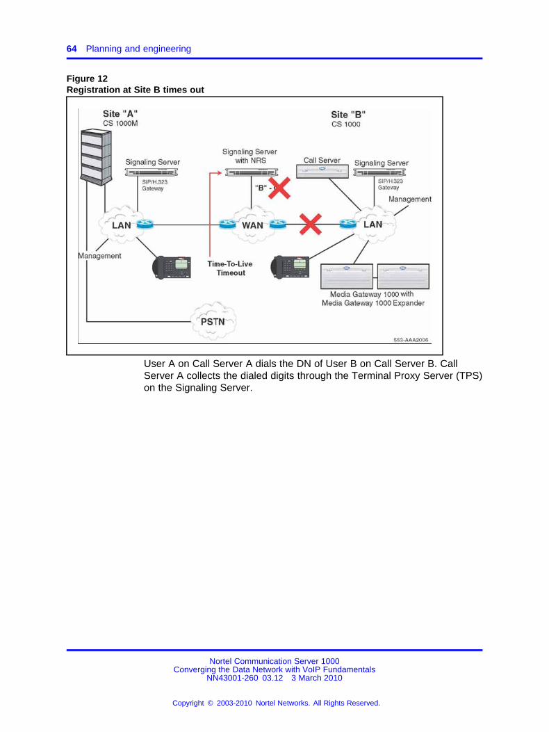
64 Planning and engineering
Figure 12Registration at Site B times out
User A on Call Server A dials the DN of User B on Call Server B. CallServer A collects the dialed digits through the Terminal Proxy Server (TPS)on the Signaling Server.
Nortel Communication Server 1000Converging the Data Network with VoIP Fundamentals
NN43001-260 03.12 3 March 2010
Copyright © 2003-2010 Nortel Networks. All Rights Reserved.
.

IP network best practices 65
Figure 13User A dials User B
Call Server A determines that the DN is at another site. Call Server Aselects the codec list, allocates bandwidth, and routes the call to the IPnetwork, using a virtual trunk and the SIP/H.323 Gateway.
To select the virtual trunk to use for routing, Call Server A examines thenumber dialed and uses various trunk routing and signaling features (forexample, ESN and MCDN).
Nortel Communication Server 1000Converging the Data Network with VoIP Fundamentals
NN43001-260 03.12 3 March 2010
Copyright © 2003-2010 Nortel Networks. All Rights Reserved.
.

66 Planning and engineering
Figure 14Call Server A routes the call to the IP network
SIP/H.323 Gateway A asks the NRS to search for a dialed DN in thedatabase (for example, within the appropriate CDP domain). The NRSreplies that no SIP/H.323 Gateways are available for the dialed number.
Nortel Communication Server 1000Converging the Data Network with VoIP Fundamentals
NN43001-260 03.12 3 March 2010
Copyright © 2003-2010 Nortel Networks. All Rights Reserved.
.

IP network best practices 67
Figure 15No SIP/H.323 Gateways are available for the dialed DN
SIP/H.323 Gateway A replies to Call Server A with a message that all IPtrunks are busy for the dialed DN.
Nortel Communication Server 1000Converging the Data Network with VoIP Fundamentals
NN43001-260 03.12 3 March 2010
Copyright © 2003-2010 Nortel Networks. All Rights Reserved.
.

68 Planning and engineering
Figure 16SIP/H.323 Gateway A replies to Call Server A
Call Server A chooses the next route in the Route List Data Block. Thenext route is a local PSTN trunk route. Call Server A allocates a VoiceGateway Media Card and PRI channel. Digit manipulation is applied to theroute using the local PSTN. A successful call is made.
Nortel Communication Server 1000Converging the Data Network with VoIP Fundamentals
NN43001-260 03.12 3 March 2010
Copyright © 2003-2010 Nortel Networks. All Rights Reserved.
.

IP network best practices 69
Figure 17Call Server A chooses the next route in the Route List Data Block
The call is routed across PSTN and enables the users to talk to eachother. The call is terminated over PSTN to Site B.
Nortel Communication Server 1000Converging the Data Network with VoIP Fundamentals
NN43001-260 03.12 3 March 2010
Copyright © 2003-2010 Nortel Networks. All Rights Reserved.
.

70 Planning and engineering
Figure 18Call is terminated over PSTN
Bandwidth ManagementThis section describes how the Bandwidth Management feature works,and is useful when considering how to engineer a network of Call Servers.
VoIP Bandwidth Management zonesBandwidth Management zones divide IP Phones and Voice GatewayMedia Cards into logical groups (zones) to determine codec selection andBandwidth Management. Zones are configured after the QoS:managed IPnetwork has been designed.
As calls are made, the Call Server software chooses a codec to be usedfor the call based on the zone configuration (interzone or intrazone). Thesoftware also tracks bandwidth usage within each zone and betweenzones. When making an interzone call, the codec is selected according tointerzone policy. This policy is a configurable value and can be configuredto BQ or BB.
Each IP Phone and Voice Gateway Media Card port is assigned a zonenumber in which it resides. Place all IP Phones and Voice Gateway MediaCards at a site in the same zone (for example, set up IP Phones andVoice Gateway Media Cards at the same branch office in the same MediaGateway 1000B [MG 1000B] zone).
Nortel Communication Server 1000Converging the Data Network with VoIP Fundamentals
NN43001-260 03.12 3 March 2010
Copyright © 2003-2010 Nortel Networks. All Rights Reserved.
.
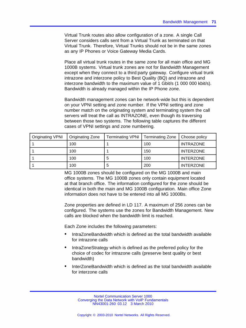
Bandwidth Management 71
Virtual Trunk routes also allow configuration of a zone. A single CallServer considers calls sent from a Virtual Trunk as terminated on thatVirtual Trunk. Therefore, Virtual Trunks should not be in the same zonesas any IP Phones or Voice Gateway Media Cards.
Place all virtual trunk routes in the same zone for all main office and MG1000B systems. Virtual trunk zones are not for Bandwidth Managementexcept when they connect to a third:party gateway. Configure virtual trunkintrazone and interzone policy to Best Quality (BQ) and intrazone andinterzone bandwidth to the maximum value of 1 Gbit/s (1 000 000 kbit/s).Bandwidth is already managed within the IP Phone zone.
Bandwidth management zones can be network-wide but this is dependenton your VPNI setting and zone number. If the VPNI setting and zonenumber match on the originating system and terminating system the callservers will treat the call as INTRAZONE, even though its traversingbetween those two systems. The following table captures the differentcases of VPNI settings and zone numbering.
Originating VPNI Originating Zone Terminating VPNI Terminating Zone Choose policy
1 100 1 100 INTRAZONE
1 100 1 150 INTERZONE
1 100 5 100 INTERZONE
1 100 5 200 INTERZONE
MG 1000B zones should be configured on the MG 1000B and mainoffice systems. The MG 1000B zones only contain equipment locatedat that branch office. The information configured for the zone should beidentical in both the main and MG 1000B configuration. Main office Zoneinformation does not have to be entered into all MG 1000Bs.
Zone properties are defined in LD 117. A maximum of 256 zones can beconfigured. The systems use the zones for Bandwidth Management. Newcalls are blocked when the bandwidth limit is reached.
Each Zone includes the following parameters:
• IntraZoneBandwidth which is defined as the total bandwidth availablefor intrazone calls
• IntraZoneStrategy which is defined as the preferred policy for thechoice of codec for intrazone calls (preserve best quality or bestbandwidth)
• InterZoneBandwidth which is defined as the total bandwidth availablefor interzone calls
Nortel Communication Server 1000Converging the Data Network with VoIP Fundamentals
NN43001-260 03.12 3 March 2010
Copyright © 2003-2010 Nortel Networks. All Rights Reserved.
.

72 Planning and engineering
• InterZoneStrategy which is defined as the preferred strategy for thechoice of codec for interzone calls
• ZoneIntent which determines whether the Zone is part of the mainoffice, a branch office (Media Gateway 1000B [MG 1000B]), or aVirtual Trunk.
• ZoneResourceType which is either shared or private. Resources inprivate zones are accessible to users in the same Zone. This allowsresources, such as DSPs, to be reserved for users in the private Zone.
For more information about Bandwidth Management Zone commands, seeTable 53 "LD 117 – Configure Bandwidth Management zone" (page 256).
The intrazone and interzone bandwidth is entered in kbit/s (for example,2.7 Mbit/s equals 2700 kbit/s). Each bandwidth zone must have theintrazone and interzone bandwidth values entered.
Zone 0 operates as a default zone when there are no IP voice zonesconfigured in LD 117. Zone 0 can then be configured as a default zone forITG Physical TNs (IPTN) in LD 14 and for virtual line in LD 11. However,if additional zones are required by an IP Phone or IPTN, zone 0 must beconfigured first
ATTENTIONWhen you move an IP Phone, the system administrator checks and changes, ifnecessary, the zone assignment of the telephone in LD 11. See Software InputOutput Reference — Administration (NN43001-611) ().
CAUTIONZone 0 must be configured in LD 117 before other zones areconfigured or all calls associated with Zone 0 are blocked.
Do not configure endpoints in bandwidth Zone 0 if you plan to use NetworkBandwidth Management. Configure Zone 0, but do not use it. Ensure thatno endpoints (for example, IP Phones, VGWs, or virtual trunks) exist inZone 0.
Nortel Communication Server 1000Converging the Data Network with VoIP Fundamentals
NN43001-260 03.12 3 March 2010
Copyright © 2003-2010 Nortel Networks. All Rights Reserved.
.

Bandwidth Management 73
CAUTIONIt is possible that the Bandwidth Management zone is alreadyprovisioned for IP Phones, Virtual Trunks, and/or VGW for yournetwork even though they do not exist in LD 117. This canoccur when upgrading from a release prior to version 4.5 toa new release greater than version 4.5. New installations ofCommunication Server 1000 release 4.5 can catch and preventthe above scenario as the Bandwidth Management featureis enhanced. It is still mandatory to configure all zones (onceonly) that are used for upgrades to release 4.5 and higher.Release 4.5 and higher upgrades convert the old database to anew release database but do not create non:existent zones. Ifthe zones are not configured, using non:existent zones in callprocessing can result in blocked calls.
Relationship between zones and WLAN setsThe existing Communication Server 1000 software bandwidthmanagement mechanism, using bandwidth zones, applies to the handsetsin the same manner as it does for IP Phones.
For more information see, WLAN IP Telephony Installation andCommissioning (NN43001:504)
Interzone versus IntrazoneFor Bandwidth Management, a network of Call Servers is divided intozones, typically one Zone for each Call Server. Calls between zonesare interzone calls and calls within a Zone are intrazone calls. Typically,intrazone calls travel over LANs on which bandwidth is widely available.Conversely, interzone calls travel over WANs on which bandwidth can belimited and expensive. Distinguish between intrazone and interzone VoIPcalls for increased control over VoIP traffic.
The following call scenarios describe how each call type works.
Intrazone call An intrazone call works as follows:
• An intrazone call is made between two endpoints on the same CallServer.
• The intrazone treatment is consulted to determine whether it is BestBandwidth or Best Quality.
• Based on the intrazone treatment, the correct codec is selected.
• The intrazone bandwidth table is also consulted to determine if there isenough intrazone bandwidth to support the call. If there is not enoughbandwidth, the call is blocked.
Nortel Communication Server 1000Converging the Data Network with VoIP Fundamentals
NN43001-260 03.12 3 March 2010
Copyright © 2003-2010 Nortel Networks. All Rights Reserved.
.

74 Planning and engineering
Interzone call An interzone call works as follows:
• An interzone call is made between two Call Servers.
• An interzone call is made between an endpoint in one Zone to anotherendpoint in a different Zone. The Zone of the endpoints are comparedto the Virtual Trunk Zone as the two zones are different, the call is aninterzone call.
• The interzone treatment is consulted to determine whether it is BestBandwidth or Best Quality.
• Based on the interzone treatment, the correct codec list is selected forthe call setup. For more information about codec selection, see “Codecselection” (page 58).
• The interzone bandwidth table and the virtual trunk bandwidth limit arealso consulted to determine if there is enough intrazone bandwidth tosupport the call. If there is not enough bandwidth, the call is blocked,or alternate treatment is provided.
Nodal Bandwidth ManagementBandwidth Management is controlled independently on each Call Serverin the network. Each Call Server acts independently of other Call Serversin the network when calculating bandwidth used, and when blocking orrerouting calls. Often referred to as nodal Bandwidth Management, eachnode, or Call Server, independently controls the Bandwidth Management.Therefore, the parameters used in configuring Bandwidth Managementmust be configured on each Call Server.
The Bandwidth Management at the branch office is controlled by theassociated main office. For the main office to keep track of the bandwidthgoing to and from the branch office, calls must tandem through the mainoffice Call Server. The signaling for the call goes through the main office,but the media path is not direct between endpoints.
VPNI and Zone numbersNetwork Bandwidth ZoneFor Network Bandwidth Management to work correctly in a CommunicationServer 1000 network, each Call Server must be configured with a uniqueNetwork Bandwidth Zone. You can choose from 255 (1 to 255) Zonenumbers in a Communication Server 1000 Call Server. To allow thenetwork to expand beyond the 255 zones, the Virtual Private NetworkIdentifier (VPNI) is combined with the Zone number to form a uniqueNetwork Bandwidth Zone. The Communication Server 1000 system allowsup to 16 383 VPNIs, which result in a total of 4 152 165 unique NetworkBandwidth Zones. A Call Server typically has one VPNI and one Zonenumber for IP Phones and IP gateways. For example, Call Server A isprovisioned with VPNI 53 and Zone 21. Each IP Phone has two zone
Nortel Communication Server 1000Converging the Data Network with VoIP Fundamentals
NN43001-260 03.12 3 March 2010
Copyright © 2003-2010 Nortel Networks. All Rights Reserved.
.
Bandwidth Management 75
properties—configured zone and current zone. Configured zone is thezone chosen by the administrator and current zone identifies who thezone IP Phone currently belongs to based on the VO login. For moreinformation, see “Bandwidth Management support for Network Wide VirtualOffice” (page 287).
ATTENTIONZone 0 is not supported by most of the Network Bandwidth Managementfeatures.
VPNI and Zone numbering rulesIf bandwidth zone numbers are duplicated on different call servers withthe same VPNI then the calls will receive INTRAZONE call treatment. Ifyou need to ensure INTERZONE call treatment then you to need ensurebandwidth zone numbers are not duplicated.
Branch office Call Servers associated with a main office must have thesame VPNI number as the main office for correct operation of the NetworkBandwidth Management feature.
For a branch office associated with a main office, the branch office Zonenumber must be different than the main office Zone number. For example,MO VPNI=22, MO Zone=33, BO VPNI=22, BO Zone=34. The branchoffice Zone number is provisioned at both the branch office and the mainoffice; configured in LD 117 on the main office and MG 1000B.
The VPNI is also used to identify a customer network. For example, thesame VPNI is required for Bandwidth Management support for the NetworkWide Virtual Office and Alternative Call Routing features, and GeographicRedundancy.
The provisioned Zone number is also used for other features in theCommunication Server 1000 network. For more information, seeEmergency Services Access Fundamentals (NN43001-613) ().
Disabling Bandwidth ManagementBandwidth Management may be disabled by provisioning the VPNI to 0 inLD 15. The local Bandwidth Management feature will continue the codeccalculation process and call blocking, therefore; you must configure theBandwidth zones with the maximum available bandwidth.
Provision the Intrazone bandwidth limit and Interzone bandwidth to themaximum (1 Gbit/s or 1 000 000 kbit/s) in LD 117. By default, the VirtualTrunk is configured with the maximum bandwidth limit.
Nortel recommends that you do not mix enabled and disabled BandwidthManagement zones in the network.
Nortel Communication Server 1000Converging the Data Network with VoIP Fundamentals
NN43001-260 03.12 3 March 2010
Copyright © 2003-2010 Nortel Networks. All Rights Reserved.
.

76 Planning and engineering
Relationship between zones and subnetsIP Phones and Voice Gateway Media Cards gateway ports are assignedto zones based on the Bandwidth Management requirements of theparticular installation. Devices in different subnets must traverse a routerto communicate and can reside on different ends of a WAN facility.When IP Phones and gateway ports are in different subnets, the networkfacilities between them must be examined to see if it warrants placing theseparated devices in different zones.
It is not necessary to always assign different zones. For instance, therecan be different subnets within a LAN interconnected by routers withsufficient bandwidth. The IP Phones, and gateway channels spread acrossthem, could all reside in a single zone. However, if there is a WAN facilitywith limited bandwidth exists between two subnets, the devices on theopposite ends should be placed in different zones so the bandwidth acrossthe WAN can be managed.
For remote users, such as telecommuters, Bandwidth Management isnot normally a consideration because only one IP Phone is present atthe remote location. It can be convenient to allocate zones for userswith similar connection speeds. In that case, set both the interzone andintrazone codec to Best Bandwidth.
Adaptive Network Bandwidth ManagementThe Adaptive Network Bandwidth Management feature enhances theperformance of VoIP networks based on real:time interaction. It providesthe means to automatically adjust bandwidth limits and take correctiveaction in response to QoS feedback. The dynamic bandwidth adjustmentmaintains a high level of voice quality during network degradation.
The Adaptive Network Bandwidth Management feature dynamically adaptsto QoS in the network and reduces the bandwidth available for interzonecalls if QoS degrades. Typically, each Call Server in the network has aZone assigned to it. The Call Server keeps track of the bandwidth beingused between its own Zone and zones that belong to other Call Servers.If the QoS degrades between the Call Server Zone and a particular Zonethat belongs to another Call Server, the available bandwidth reducesautomatically between those two zones. When the QoS between the twozones improves, then the bandwidth limit returns to normal.
When an IP Phone encounters degradation of the network, it informs theCall Server through various QoS alarms (packet loss, jitter, delay; and, forphase 2 IP Phones, R value). Depending upon the rate of the incomingalarms and the value of the alarms, the Call Server reduces the availablebandwidth to make new calls. The Call Server lowers, limits, or both thenumber of new calls allowed, based on the available bandwidth to preventexcessive calls on a network with limited bandwidth (resulting in poor voice
Nortel Communication Server 1000Converging the Data Network with VoIP Fundamentals
NN43001-260 03.12 3 March 2010
Copyright © 2003-2010 Nortel Networks. All Rights Reserved.
.

Bandwidth Management 77
quality). After the adjusted (lowered) bandwidth reaches its full capacity,new calls are either routed to an alternate route (if available), usingNetwork Alternate Routing Service (NARS) or the Alternative Routing forthe Network Bandwidth Management feature, or new calls are blocked.The Call Server continues to monitor the network throughout the networkdegradation period. When the degradation is removed or the performanceof the network improves, the allowable bandwidth returns to provisionedlevels and the Call Server gradually starts to allow new calls.
Essentially, Adaptive Network Bandwidth Management provides a fallbackto PSTN on QoS degradation for new calls. As a result, bandwidth ismanaged and quality measured between all zones across the entirenetwork, and corrective action taken when necessary. Due to the real:timeinteraction with the network, less maintenance is required for the networkas the system reacts automatically to network conditions.
With Adaptive Network Bandwidth Management, it is not necessary toprovision bandwidth parameters between every Zone in the network.Rather, the Call Server automatically learns of new zones in the networkand applies Adaptive Network Bandwidth Management to these newzones as required. As new Call Servers are added to the network, it isnot necessary to reprovision all the other Call Servers on the network.Conversely, when Call Servers are removed from the network, theremaining Call Servers age out the old Call Server information and provideonly up to date bandwidth information.
The Adaptive Network Bandwidth Management feature operates betweenall IP Peer Communication Server 1000 systems, including the MediaGateway 1000B and Survivable Remote Gateway 50.
Call scenarioA call is requested from a telephone in VPNI 1/Zone 2 on Call Server A toa telephone in VPNI 3/Zone 3 on Call Server B. Both zones have AdaptiveNetwork Bandwidth Management enabled.
1. Call Server A contacts the Network Redirect Server to obtain theaddress of Call Server B.
2. Call Server A sends a call setup message to Call Server B, identifyingthe calling telephone’s VPNI and Zone.
3. Call Server B determines if there is sufficient bandwidth for the call,and sends back the VPNI and Zone of the called telephone.
Nortel Communication Server 1000Converging the Data Network with VoIP Fundamentals
NN43001-260 03.12 3 March 2010
Copyright © 2003-2010 Nortel Networks. All Rights Reserved.
.

78 Planning and engineering
4. Call Server A checks its bandwidth table to determine if there issufficient bandwidth available for the call from Call Server A to CallServer B.
5. If Call Server A determines there is enough bandwidth available, thecall is established; otherwise, alternate treatment is provided (blockor reroute the call).
Both Call Server A and Call Server B must consult their own bandwidthtables to determine if there is enough bandwidth for the call to proceed.
Figure 19Call Progress with Adaptive Network Bandwidth Management
Nortel Communication Server 1000Converging the Data Network with VoIP Fundamentals
NN43001-260 03.12 3 March 2010
Copyright © 2003-2010 Nortel Networks. All Rights Reserved.
.

Bandwidth Management 79
Zone Bandwidth Management and Adaptive Network BandwidthManagementUsing Element Manager or the command line interface (CLI), previouslyconfigured zones (except Zone 0) can have the Adaptive NetworkBandwidth Management feature turned on or off. After turned on, alarmthreshold levels and the QoS coefficients can be adjusted from the defaultvalues. Adaptive Network Bandwidth Management cannot be enabled forZone 0.
When Adaptive Network Bandwidth Management is enabled for aparticular Zone on the Call Server, the Zone appears in the Zone table.The Zone table can be displayed using Element Manager or LD 117.When a call is made from the configured Zone to another Zone, thebandwidth used appears in the Zone table.
When a call is made from a Zone with Adaptive Network BandwidthManagement enabled to a third:party gateway with no Zone, the Zone ofthe Virtual Trunk (VTRK) is used and appears in the Zone table.
Figure 20 "Adaptive Network Bandwidth Management graph" (page79) depicts an example of bandwidth changes.
Figure 20Adaptive Network Bandwidth Management graph
When a Call Server receives a QoS alarm, the two zones that originatedthe alarm are determined. Using this information, the Call Serverreduces the bandwidth limit between the two zones. This Zone:to:Zonebandwidth limit (in effect at any particular time) is known as the SlidingMaximum Bandwidth Limit and is a percentage of the Configured Interzonebandwidth limit. The Sliding Maximum value is displayed using the prt
Nortel Communication Server 1000Converging the Data Network with VoIP Fundamentals
NN43001-260 03.12 3 March 2010
Copyright © 2003-2010 Nortel Networks. All Rights Reserved.
.

80 Planning and engineering
interzone command. The QoS Factor % value is also displayed as thepercentage of the Sliding Maximum versus the configured allowablebandwidth. The Call Server checks the Network Bandwidth Zonemanagement tables for the originating and terminating zones of the newcall to determine the available bandwidth for the call.
For more information about alarms, see Software Input Output Reference— System Messages (NN43001-712) () .
When feedback indicates a significant QoS change in a Zone, the CallServer reduces the available bandwidth (Sliding Maximum BandwidthLimit) in the Zone until the QoS reaches a satisfactory level. Aftersatisfactory QoS is reached, the bandwidth is slowly raised until eitherthe full bandwidth is available or until QoS degrades again. Bandwidthchanges can be configured to be gradual (to reduce rapid swings andvariations) or rapid.
Multiple Appearance Directory Numbers (MADN) can exist on differentzones. Calls to an MADN are handled the same as other IP Phone calls,and are subject to the same bandwidth limitations.
SNMP alarms monitor the system. When the bandwidth limit betweenzones is reduced below configured levels, an alarm is raised. A Warningalarm and an Unacceptable alarm, each corresponding to a dropbelow a configured threshold, are used. When the bandwidth returnsto normal, the alarm is cleared. If the bandwidth limit reaches zero, anadditional Unacceptable alarm is raised. These alarms allow the systemadministrator to monitor the system and take corrective action whenrequired.
Adaptive Network Bandwidth Management configurationparametersPacket Loss (pl), Jitter (j) and Delay (d) measurements, along with the Rfactor (r) in IP Phone 200x Phase II telephones, are used to calculate theQoS level for the zones. The coefficients for these QoS measurements— Packet Loss (Cpl), jitter (Cj), delay (Cd), and the R factor (Cr) — canbe configured and are used to calculate the rate of bandwidth change.Increasing the coefficients from their default values causes the SlidingMaximum to decrease faster in response to the specific QoS alarm.
The QoS coefficient (CQoS) can be varied from its default value.Increasing this value causes the Sliding Maximum to change more rapidlyin response to QoS alarms. Making this value too large will result in lossof overall bandwidth. The following tables illustrate the effect of the defaultand a high CQos coefficient.
Nortel Communication Server 1000Converging the Data Network with VoIP Fundamentals
NN43001-260 03.12 3 March 2010
Copyright © 2003-2010 Nortel Networks. All Rights Reserved.
.

Bandwidth Management 81
Figure 21Effect of the default CQos coefficient
Figure 22Effect of a high CQoS coefficient
Other configurable coefficients used in the calculation are the QoSCoefficient (CQoS), QoS Response Time Increase (ZQRT), and QoSResponse Time Interval (ZQRTI). The coefficients CQoS, Cr, Cd, Cpl, andCj control the rate of bandwidth decrease, while ZQRT and ZQRTI controlthe rate of bandwidth increase.
The Call Admission Control Validity Time Interval (CACVT) is used tocontrol the length of time that records from a Call Server are saved in theBandwidth Management table. If no calls occur between two Call Serverswithin the configured time, the Call Server is removed from the table. Forexample, if Call Server A has Call Server B in the table, and no call isplaced between A and B for the CACVT time, then Call Server A removesall Call Server B records in the table.
Feature interactions Virtual Office IP Phones are not subject tobandwidth limitations. They may not have the correct zone informationconfigured. They can also be controlled by a Call Server that is not
Nortel Communication Server 1000Converging the Data Network with VoIP Fundamentals
NN43001-260 03.12 3 March 2010
Copyright © 2003-2010 Nortel Networks. All Rights Reserved.
.

82 Planning and engineering
responsible for the particular zone. Thus, Bandwidth Management is notpossible for these phones.
Feature packagingThe Adaptive Network Bandwidth Management feature requires thefollowing packages.
• QoS Enhanced Reporting (PVQM) package 401
• Call Admission Control (CAC) package 407
ATTENTIONPackage 401, QoS Enhanced Reporting (PVQM), is required if the R value fromthe Phase II IP Phones is reported and used to calculate the QoS level for thezones.
VoIP network voice engineering considerationsIt may be necessary to calculate CCS between zones to determine if thenetwork can support the required call volume.
For more information, see the following:
• “Network Bandwidth Management” (page 21)
• Communication Server 1000M and Meridian 1 Large System Planningand Engineering (NN43021-220) ()
Determine interzone and intrazone bandwidth valuesThe Call Server uses the values shown in Table 5 "Bandwidth estimatesused by Call Admission Control" (page 83) when calculating the bandwidtheach call uses in a zone. The Call Server uses the values in the TLANBandwidth columns and subtracts the value from the available zonebandwidth to determine if a zone has sufficient bandwidth for the call.
ATTENTIONDo not change, load, or transfer codec lists onto a node during active callprocessing. Complete changes to codec lists during scheduled maintenancewindows when the system is idle.
Call Admission Control (CAC) mechanisms on the Call Server assumeaverage bandwidth utilization for Voice Activity Detection (VAD) codecs.
Nortel Communication Server 1000Converging the Data Network with VoIP Fundamentals
NN43001-260 03.12 3 March 2010
Copyright © 2003-2010 Nortel Networks. All Rights Reserved.
.

Bandwidth Management 83
Table 5Bandwidth estimates used by Call Admission Control
TLAN Bandwidth(half:duplex,
payload/RTP/UDP/IP/Ethernet)
Base WAN Bandwidth(full:duplex,
payload/RTP/UDP/IP)
CODECtype
Packetduration
(ms)
Voicepayload(bytes) VAD
Peakbandwidth
(kbit/s)
Averagebandwidth
(kbit/s)
Peakbandwidth
(kbit/s)
Averagebandwidth
(kbit/s)
10 80 Off 252.80 252.80 96.00 96.00
20 160 Off 190.40 190.40 80.00 80.00
G.711(64 kbit/s)
30 240 Off 169.60 169.60 74.67 74.67
10 10 Off 140.80 140.80 40.00 40.00
20 20 Off 78.40 78.40 24.00 24.00
30 30 Off 57.60 57.60 18.67 18.67
40 40 Off 47.20 47.20 16.00 16.00
G.729A(8 kbit/s)
50 50 Off 40.96 40.96 14.40 14.40
10 10 On 140.80 84.48 40.00 24.00
20 20 On 78.40 47.04 24.00 14.40
30 30 On 57.60 34.56 18.67 11.20
40 40 On 47.20 28.32 16.00 9.60
G.729AB(8 kbit/s)
50 50 On 40.96 24.58 14.40 8.64
G.723.1(6.3
kbit/s)
30 24 Off 54.40 54.40 17.07 17.07
G.723.1(5.3
kbit/s)
30 24 Off 54.40 54.40 17.07 17.07
ATTENTIONSecure Real:Time Transport Protocol (SRTP) adds 10 extra bytes per mediapacket. This is not significant in the calculation of bandwidth.
The TLAN Bandwidth values contain the total IP and Ethernet packetoverhead of 78 bytes, including the 8:byte preamble and minimum 12:byteinter:packet gap. Ensure to include the TLAN Bandwidth values in yourbandwidth calculations to give a true indication of the bandwidth used. TheCall Server assumes that all calls are made over a half:duplex Ethernetnetwork.
The Call Server is unaware of the particulars of the WAN facility andalways uses the values shown in the TLAN Bandwidth columns.
Nortel Communication Server 1000Converging the Data Network with VoIP Fundamentals
NN43001-260 03.12 3 March 2010
Copyright © 2003-2010 Nortel Networks. All Rights Reserved.
.

84 Planning and engineering
The columns labeled Base WAN Bandwidth provide the data for thepayload plus IP overhead without the Ethernet interface overhead.This data provides the basis for any WAN bandwidth calculations. Theoverhead associated with the particular WAN facility (for example, FrameRelay) is added to the base value to determine the total bandwidth used.The values shown are for a half:duplex link, so if the WAN facility ishalf:duplex, the values should be doubled. This should be consideredwhen entering the intrazone and interzone bandwidth values for a zone inLD 117.
The IP/UDP/RTP header size is 40 bytes.
Calculate the bandwidth amountCalculate the bandwidth amount to enter into the bandwidth zone tableas described below.
Calculating the bandwidth amount for the bandwidthzone table
Step Action
1 Determine the number of calls that the network can support forthe chosen codec.
2 Multiply the half:duplex Ethernet bandwidth by the valuedetermined in step 1.
3 Enter the value determined in step 2 in the Call Serverbandwidth zone table.
--End--
Ensure that the efficiency of the network transporting VoIP is taken intoaccount when you enter the amount of zone bandwidth available. Formore information, see the efficiency example in “Bandwidth and datanetwork switch efficiency” (page 112).
Determine intrazone bandwidthUse the following steps to determine intrazone bandwidth.
Nortel Communication Server 1000Converging the Data Network with VoIP Fundamentals
NN43001-260 03.12 3 March 2010
Copyright © 2003-2010 Nortel Networks. All Rights Reserved.
.

Bandwidth Management 85
ATTENTIONDetermination of intrazone bandwidth is not normally required as a large amountof bandwidth is normally available within a local network, so an arbitrarily largevalue can be entered for the interzone available bandwidth.
If required, interzone bandwidth is calculated using the same procedure as forintrazone bandwidth.
Determining intrazone bandwidth
Step Action
1 Determine the VoIP codec and packet duration to use forinterzone calls.
2 Determine the network duplex, Layer 2 protocol, and Layer 2protocol header size between zones.
3 Determine the total available bandwidth for voice on the datanetwork.
4 Calculate the per:call bandwidth to use for the codec (from step1) over the Layer 2 network (from step 2).
Per:call bandwidth for a particular Layer 2 network:(1000 / Packet Duration [ms]) x (Voice payload Bytes) + IP/ UDP /RTP Size (Bytes) + Layer two Protocol Header Size[Bytes]) x 8
Alternatively, see “VoIP Bandwidth Demand Calculator” (page140) .
5 Calculate the number of calls the network can handle, by dividingthe total bandwidth available for voice over the Layer 2 network(from step 3) by the real per:call bandwidth use for the codec(from step 4).
6 Determine the half:duplex Ethernet bandwidth for one call for thecodec (from step 1) to use.
See Table 5 "Bandwidth estimates used by Call AdmissionControl" (page 83).
7 Calculate the bandwidth value to enter into the Call ServerBandwidth Management zone, by multiplying the half:duplexEthernet bandwidth (from step 6) by the number of calls thenetwork can handle.
--End--
Determine interzone bandwidth The following example is based onBandwidth Management of G.729A interzone traffic over a 512 kbit/sFrame Relay network.
Nortel Communication Server 1000Converging the Data Network with VoIP Fundamentals
NN43001-260 03.12 3 March 2010
Copyright © 2003-2010 Nortel Networks. All Rights Reserved.
.

86 Planning and engineering
Example of determining interzone bandwidth calculation
Step Action
1 Codec = G.729A, 20ms.
2 Network type = Full duplex Frame Relay with 6:byte header.
3 Total bandwidth available = 512 kbit/s * 0.9 = 460.8 kbit/s .
0.9 is an estimate of the efficiency of a random Frame Relayrouter. The actual efficiency may vary. See calculating datanetwork switch efficiency in “Bandwidth and data network switchefficiency” (page 112).
4 G.729A per:call bandwidth on a full duplex frame relay network =(1000 / 20) * (20 + 40 + 6) * 8 = 26400 bps = 26.4 kbit/s.
5 Total calls possible = 460.8 kbit/s / 26.4 kbit/s = 17 calls.
6 G.729A half:duplex Ethernet per:call bandwidth = 78.4 kbit/s.
7 Call Server bandwidth value = 78.4 kbit/s * 17 calls = 1333 kbit/s.Enter 1333 kbit/s in the Call Server.
--End--
ATTENTIONThe use of IP Call Recording doubles the bandwidth requirements of thecall. For remote users connecting to the IP Call Recorder server through aWAN connection, the impact of the bandwidth usage to the QoS should beconsidered. In this case, the IP Call Recorder server must provide the QoSparameters when instructing the IP Phone to echo the voice data. For moreinformation about the Feature Interactions for IP Call Recording, see AutomaticCall Distribution Fundamentals (NN43001-551) () .
Viewing bandwidth statisticsUse the prt intrazone and prt interzone commands in LD 117 to display thebandwidth statistics in the Call Server. For more information about thesecommands, see Software Input Output — Maintenance (NN43001-711) () .For examples on the output of these commands, see Figure 23 "Sampleoutput for prt intrazone command" (page 87) and Figure 24 "Sample outputfor prt interzone command" (page 87) .
Nortel Communication Server 1000Converging the Data Network with VoIP Fundamentals
NN43001-260 03.12 3 March 2010
Copyright © 2003-2010 Nortel Networks. All Rights Reserved.
.

Bandwidth Management 87
Figure 23Sample output for prt intrazone command
Figure 24Sample output for prt interzone command
Tandem Bandwidth ManagementBandwidth utilization for the branch office is tracked at the main office andcan be displayed in LD 117 using the prt interzone command. To providethe correct bandwidth utilization to the main office Call Server, when abranch office is calling another node in the network, the calls must betandemed through the main office Call Server in both the inbound andoutbound direction.
If you enter the main office Gateway endpoint identifier in the TandemEndpoint field for each branch office gateway configured on the NRS, ittandems only in the outbound direction from each branch office (frombranch office to main office).
Nortel Communication Server 1000Converging the Data Network with VoIP Fundamentals
NN43001-260 03.12 3 March 2010
Copyright © 2003-2010 Nortel Networks. All Rights Reserved.
.

88 Planning and engineering
To tandem calls through the main office in the inbound direction (frommain office to branch office), use the dialing plan capabilities of theCommunication Server 1000 to first route the call to the main office. Themain office appends a prefix to the dialed number and the number isrouted to the branch office.
Tandem all branch office calls through the main office, so the main officecan monitor the bandwidth used at each branch office.
The Tandem Bandwidth Management feature applies to the branch officeand the Adaptive Bandwidth Management feature. Specifically, the featureapplies to calls made to and from the branch office from either telephonesregistered locally at the branch office (digital, analog [500/2500:type]telephones, and IP Phones) or trunks at the branch office to another nodein the network. The feature does not apply when you use branch office IPPhones registered with the main office (for example, Normal Mode).
Codec negotiationCodec refers to the voice coding and compression algorithm used byDSPs. Each codec has different QoS and compression properties.
IP Peer Networking supports the per:call selection of codec standards,based on the type of call (interzone or intrazone). IP Peer Networkingsupports the following codecs with supported payload sizes (the defaultvalue is in bold).
Table 6Supported codecs
Codec Payload size
G.711 A/mu:law 10 millisecond (ms), 20 ms, and 30 ms
G.729 A 10 ms, 20 ms, 30 ms, 40 ms, and 50 ms
G.723.1 30 ms, although it can limit the number of DSP channels available
T.38 for fax Supported for fax calls on gateway channels
G.711 ClearChannel
Supported on the MC32S and DSP d/bs (Mindspeed) and not on the MC32cards
The G.XXX series of codecs are standards defined by the InternationalTelecommunications Union (ITU).
By default, the G.711 codec must be supported at both ends of a call.Codec configuration is performed for each node and is independent ofthe signaling gateway (SIP or H.323) that is used on the node. T.38 isthe preferred codec type for fax calls over virtual trunks. However, theG.711 Clear Channel codec is used if the far-end does not support theT.38 codec.
Nortel Communication Server 1000Converging the Data Network with VoIP Fundamentals
NN43001-260 03.12 3 March 2010
Copyright © 2003-2010 Nortel Networks. All Rights Reserved.
.

Bandwidth Management 89
If a Communication Server 1000E system is used, the same payloadsizes for the same codec type should be configured on all InternetProtocol Media Gateway (IPMG) cabinets in a system; otherwise, TimeDivision Multiplexing (TDM) to TDM calls between IPMG cabinets are notsuccessful.
If more than one codec is configured, the minimum payload sizeamong the configured codecs is used for the SIP Trunk Gateway codecnegotiation.
For more information about the codecs that are supported for IP phones,see IP Phones Fundamentals (NN43001-368) () and Signaling Server IPLine Applications Fundamentals (NN43001-125). ().
ATTENTIONNortel recommends that you configure the same payload size for all codecs inthe same node. The payload size on the Communication Server 1000 systemmust be set to 30 ms to work with the SRG.
Ensure common codecs across the network, especially in tandem calls acrossdifferent protocols, for example, H.323 tandem to SIP or SIP to H.323. TheSession Description Protocol (SDP) transparency helps in this case; however,when you tandem through different trunks over different protocols, codecs mustmatch.
SIP exampleIf a G.711 20 ms codec and G.729 30 ms codec are configured, thencodec negotiation uses the minimum payload size of 20 ms. That is, theG.711 20 ms codec and the G.729 20 ms codec are used. Instead, Nortelrecommends that both G.711 and G.729 codecs be configured as 20 ms.
When a G.729 30 ms codec is configured, the G.729 10ms/20ms/30mscodecs are supported.
IP Peer Networking performs codec negotiation by providing a list ofcodecs that the devices can support. Use Communication Server 1000Element Manager to configure the list of codec capabilities.
The codec preference sequence sent over SIP/H.323 depends on thebandwidth policy selected for the Virtual Trunk zone and the involvedtelephones. For Best Quality, the list is sorted from best to worst voicequality. For Best Bandwidth, the list is sorted from best to worst bandwidthusage.
The G.711 codec delivers toll quality audio at 64 kbit/s. The G.711 codecis optimal for speech quality, as it has the smallest delay and is resilient tochannel errors. However, the G.711 codec uses the largest bandwidth.
Nortel Communication Server 1000Converging the Data Network with VoIP Fundamentals
NN43001-260 03.12 3 March 2010
Copyright © 2003-2010 Nortel Networks. All Rights Reserved.
.

90 Planning and engineering
The G.729A codec provides near toll quality voice at a low delay. TheG.729A codec and G.729AB codecs use compression at 8 kbit/s.
The G.723.1 codec provides the greatest compression compared to thepreviously described codecs.
Payload default values need to be changed if the customer wants tocommunicate with a third:party gateway that does not support the abovedefault payload sizes. Otherwise, IP Peer calls to or from the third:partygateway are not successful.
If the payload sizes are set higher than the default values (for example,to support a third:party gateway), then the local IP calls are affected byhigher latency because the codec configuration applies to both IP Peercalls and local IP (IP Line) calls.
If a Communication Server 1000E system is used, the same payload sizesfor the same codec type should be configured on all IPMG cabinets in asystem. Otherwise, TDM to TDM calls between IPMG cabinets are notsuccessful.
G.711 A:law and mu:law interworkingIn case the far end uses a different Pulse Code Modulation (PCM)encoding law for its G.711 codec, systems configured as G.711 A:law alsoinclude G.711 mu:law on their codec preferences list. Systems configuredas G.711 mu:law include G.711 A:law as their last choice. Therefore,encoding law conversion is performed between systems with differentlaws.
Bandwidth Management and codecsBandwidth Management defines the codecs to use for intrazone calls andinterzone calls.
Administrators use Bandwidth management to define codec preferencesfor IP Phone to IP Phone calls controlled by the same CommunicationServer 1000 system within the same zone (intrazone calls). Administratorsuse different codec preferences for calls between an IP Phone on theCommunication Server 1000 system to a Virtual Trunk (potentially an IPPhone on another Communication Server 1000 system) or calls to IPPhones in another zone (interzone calls).
For example, you may prefer high quality speech (G.711) over highbandwidth within one system, and lower quality speech (G.729AB) overlower bandwidth to a Virtual Trunk. Such a mechanism can be usefulwhen a system is on the same LAN as the IP Phones it controls, but theother systems are on a different LAN (connected through a WAN).
Nortel Communication Server 1000Converging the Data Network with VoIP Fundamentals
NN43001-260 03.12 3 March 2010
Copyright © 2003-2010 Nortel Networks. All Rights Reserved.
.

Bandwidth Management 91
Usage of bandwidth zones for Virtual Trunks are different than IP Phonebandwidth usage. For Virtual Trunks, a zone number is assigned in theRoute Data Block (LD 16). The zone number determines codec selectionfor interzone and intrazone calls (Best Quality).
Bandwidth usage for Virtual Trunks is accumulated in its zone to blockcalls that exceed the bandwidth availability in a specific zone. However,the amount of bandwidth required to complete a given call is not knownuntil both call endpoints negotiate which codec to use. The bandwidthused to calculate the usage of a Virtual Trunk call is determined by thepreferred codec of the device that connects to the Virtual Trunk. If thedevice is an IP Phone, the bandwidth calculations use the preferred codecof the IP Phone, based on the codec policy defined for the zones involved(Best Quality). The bandwidth calculations use the preferred codec of theVoice Gateway Media Card for connections between a circuit:switcheddevice (for example, a PRI trunk) and a Virtual Trunk.
Codec selectionFor every Virtual Trunk call, a codec must be selected before the mediapath can be opened. When a call is set up or modified (that is, mediaredirection), one of two processes occurs:
• The terminating node selects a common codec and sends the selectedcodec to the originating node.
• The codec selection occurs on both nodes.
Each node has two codec lists: its own list and the far end list. To selectthe same codec on both nodes, it is essential to use the same codecselection algorithm on both nodes. Before the codec selection occurs, thefollowing conditions are met:
• Each codec list contains more than one payload size for a given codectype (depending on the codec configuration).
• Each codec list is sorted by order of preference (the first codec in thenear end list is the near end most preferred codec, the first codec inthe far end list is the far end preferred codec).
Codec selection algorithmsWhen the codec lists meet the above conditions, one of the followingcodec selection algorithms selects the codec to be used:
• H.323 Master/Slave algorithm
• SIP Offer/Answer model
• Best Bandwidth codec selection algorithm
Nortel Communication Server 1000Converging the Data Network with VoIP Fundamentals
NN43001-260 03.12 3 March 2010
Copyright © 2003-2010 Nortel Networks. All Rights Reserved.
.

92 Planning and engineering
If a SIP trunk call is between a Communication Server 1000 system andother third:party gateway/SIP clients (for example, MCS 5100), then thecodec selection does not guarantee that the same codec is selected fora call from endpoint A to endpoint B and for a call from endpoint B toendpoint A. This different codec selection makes it difficult for BandwidthManagement. However, calls between two Communication Server 1000systems have the same codec selection decision, regardless of whooriginated the call.
In the case of a Virtual Trunk call between Nortel and third:partyequipment, the H.323 Master/Slave algorithm is used.
The codec selection algorithm proposed by the H.323 standard involvesa Master/Slave negotiation initiate each time two nodes exchange theircapabilities. The Master/Slave information decides that one node is Masterand the other node is Slave. The outcome of the Master/Slave negotiationis not known in advance; it is a random result. One node could be Masterand then Slave (or vice versa) during the same call.
Algorithm details The H.323 Master/Slave algorithm operates in thefollowing manner:
• The Master node uses its own codec list as the preferred one and findsa common codec in the far end’s list. In other words, the Master getsthe first codec in its list (for example, C1), checks in the far end’s listif it is a common codec; if it is, C1 is the selected codec. Otherwise,it gets the second codec in its list and verifies it against the far end,and so on.
• The Slave node uses the far end’s list as the preferred one and findsin its own list the common codec.
Issues caused by the H.323 Master/Slave algorithm The issuescaused by the Master/Slave algorithm are due to the random nature of theMaster/Slave information. You cannot predetermine the codec used duringa Virtual Trunk call.
The following are the issues associated with the H.323 Master/Slavealgorithm:
• After an on:hold and off:hold scenario (which triggers Master/Slavenegotiation), the codec used for the restored call might be differentthan the one used before on:hold, because the Master/Slaveinformation can change.
• When using Fast Start codec selection, a call from Telephone 1(node 1) to Telephone 2 (node 2) can use a different codec than a
Nortel Communication Server 1000Converging the Data Network with VoIP Fundamentals
NN43001-260 03.12 3 March 2010
Copyright © 2003-2010 Nortel Networks. All Rights Reserved.
.

Bandwidth Management 93
call from Telephone 2 (node 2) to Telephone 1 (node 1), because theterminating end is always Master.
• For tandem calls, the Master/Slave information is not relevant. TheMaster/Slave information is designed for use between two nodes only,not between three or more nodes as it makes the codec selection fortandem calls more complex and inefficient.
To solve the previous issues, use another codec selection algorithm,not based on the unpredictable Master/Slave information. Because anychange to the Master/Slave algorithm implies a change to the H.323standard, the new codec algorithm is used for Virtual Trunk calls betweenNortel equipment.
SIP Offer/Answer modelThe SIP codec negotiation is based on the Offer/Answer model withSession Description Protocol (SDP).
The following three cases of codec negotiation are supported:
• The calling user agent sends an SDP offer with its codec list in theinvite message with a sendrecv attribute. In this case, the calleduser agent selects one codec and sends the selected codec in anSDP answer. The SDP answer is included in the 200 OK message(response to the INVITE) with the sendrecv attribute as the preferredmethod of operation.
• The calling user agent sends an SDP offer with its codec list in theinvite message with a sendrecv attribute. The called user agent returnsmore than one codec in the SDP answer. In the case that manycodecs are included in the response, the calling user agent picks thefirst compatible codec from the called user agent list, and sends a newSDP offer with a single codec to lock it in.
• If the SDP of the calling user agent is not present in the INVITEmessage, then the called user agent sends its codec list in an SDPoffer in the 200 OK message, with the sendrecv attribute. The callinguser agent selects one codec and sends it in an SDP answer insidethe ACK message, with a sendrecv attribute.
For more information, see RFC 3264 An Offer/Answer Model with theSession Description Protocol (SDP).
Best Bandwidth codec selection algorithmThe Best Bandwidth codec selection algorithm solves the issues causedby the H.323 Master/Slave algorithm. The Best Bandwidth algorithmselects one common codec based on two codec lists. Every time theselection is done with the same two lists, the selected codec matches.
Nortel Communication Server 1000Converging the Data Network with VoIP Fundamentals
NN43001-260 03.12 3 March 2010
Copyright © 2003-2010 Nortel Networks. All Rights Reserved.
.

94 Planning and engineering
The Best Bandwidth codec decision is based on the codec type only, itdoes not consider the fact that some codecs, while generally using lessbandwidth, can consume more bandwidth than others at certain payloadsizes.
Best Bandwidth is also applicable to SIP.
Algorithm details The selected codec is the type considered as thebest bandwidth codec type. To determine if one codec type has betterbandwidth than another, see the rule as summarized in Table 7 "BestBandwidth algorithm : codec type" (page 94).
Table 7Best Bandwidth algorithm : codec type
G.711 A law G.711 mu:law G.729 A G. 729 AB G. 723.1
G.711 A:law G.711 A:law G.711 mu:law G.729 A G. 729 AB G. 723.1
G.711 mu:law G.711 mu:law G.711 mu:law G.729 A G. 729 AB G. 723.1
G.729 A G.729 A G.729 A G.729 A G. 729 AB G.729 A
G. 729 AB G. 729 AB G. 729 AB G. 729 AB G. 729 AB G. 729 AB
G. 723.1 G. 723.1 G. 723.1 G.729 A G. 729 AB G. 723.1
The SRG 50 does not support G.723 codec.
Feature interaction The SRG operates with Communication Server1000 similar to MG 1000B, but with a limitation on codec selection policy.Calls between branch IP Phones and branch analog phones are basedon the interzone policy rather than the intrazone policy defined in theCommunication Server 1000 main office. The zone table is updated basedon the intrazone policy.
The net result of this limitation is that calls between branch IP Phone usersand the branch PSTN, or between the IP Phones and branch analogphones, always use a Best Bandwidth codec. However, the calls areaccounted for as Best Quality. This may impact the perception of callquality in this scenario, but it will not result in early call blocking. Thereis no impact to codec selection or bandwidth usage tracking for calls thatrequire WAN bandwidth.
The SRG 50 does not support the G.723 codec.
Bandwidth Management parametersThe following information describes Bandwidth Management parameters.
Nortel Communication Server 1000Converging the Data Network with VoIP Fundamentals
NN43001-260 03.12 3 March 2010
Copyright © 2003-2010 Nortel Networks. All Rights Reserved.
.

Bandwidth Management parameters 95
ZonesBandwidth Management zones are configured for each endpoint on aCall Server. The Network Bandwidth zone number determines if a call isan intrazone call or an interzone call. After that is determined, the propercodec and bandwidth limit is applied to the call.
All of the endpoints on one Call Server are configured with a zone numberto identify them as belonging to a unique geographic location in thenetwork. In addition, Virtual Trunks are configured with a zone number thatis different from the endpoint zone numbers in the Call Server.
An IP Peer network is divided into different Bandwidth Management zones.Each IP Phone, Virtual Trunk, or Voice Gateway DSP channel is assignedto a Bandwidth Management zone. All IP Phones, Virtual Trunks, or VoiceGateway DSP channels in a Bandwidth Management zone.
• share the same IP Bandwidth Management policies
• are geographically near each other
• are all in the same time zone
• are all in the same PSTN dialing plan
A Bandwidth Management zone is assigned to each Virtual Trunk andVoice Gateway DS Channel in LD 14. Voice Gateway DS Channel zonemust be the same channel zone as the Route zone this channel belongsto. Channel zone is automatically populated by the Route zone and cannotbe manually configured in LD 14. This zone enables the trunk to send asetup message, with a codec list selected according to the Best Bandwidth(BB) or Best Quality (BQ) criteria for that zone.
For dialing plan purposes, all telephones in the same zone are treatedidentically. Each IP Phone is assigned to a zone during configuration.The branch office feature enables IP Phones located in more thanone geographic location to have dialing plan behaviors localized to thetelephone location, rather than the Call Server location.
IP Phones at a branch office are configured within a unique zone. In themain office Call Server, IP Phones at the branch office are assigned to abranch office zone to define the numbering plan for local, long:distance(optional), and emergency services calls. Zone configuration modifies thedialed digits so a local, long:distance (optional), or emergency servicescall can be sent to a NRS as a long:distance call. Zone configurationdata enables the main office Call Server to modify the dialed digits forthese types of calls initiated from an MG 1000B telephone. The NRS thenprovides the endpoint information to route the call to the branch office.
Different zone numbers are assigned to different MG 1000B systems.
Nortel Communication Server 1000Converging the Data Network with VoIP Fundamentals
NN43001-260 03.12 3 March 2010
Copyright © 2003-2010 Nortel Networks. All Rights Reserved.
.

96 Planning and engineering
Codec selection occurs as described in “Codec selection” (page 91).
Zone AssignmentsNortel recommends the following when assigning bandwidth zones basedon geographic location:
• Each location is assigned with a unique bandwidth zone
• IP and VGW resources that are local to the same location, areconfigured in a same bandwidth zone
• Virtual trunk resources are configured in a separate bandwidth zone
• Use the same zone number for Virtual trunk resources for all Callservers within the same network (for example, Main Office and orBranch Office configuration or MG 1000B groups or call servers withinone LAN). The reason for this is because the Virtual Trunk zone is notfactored into the decision of the Call server whether the call is treatedas a INTRAZONE or INTERZONE.
• Both intra: and interzone Virtual Trunks should be configured with BestQuality (BQ) codec and with maximum available bandwidth, such as 1000 000 kbit/s.
The following table shows an example of a system with geographicredundancy that is distributed among three locations. Zone table isconfigured once at Location 1 and then the database is to be distributedamong the systems automatically by Geographic Redundancy.
Table 8Single system in a network – Communication Server 1000E system with Survivable MediaGateway
Location 1:(Primary CommunicationServer 1000E with HighAvailability Redundant System)
Zone = 1 Intra BW = 1000000 Intra BW Strategy = BQ (BestQuality)Inter BW = 1000000 Inter BW Strategy = BB (BestBandwidth)
Location 2:(Secondary 1 MG 1000Esystem)
Zone = 2 Intra BW = 1000000 Intra BW Strategy = BQ (BestQuality)Inter BW = 1000000 Inter BW Strategy = BB (BestBandwidth)
Location 3:(Secondary 2 MG 1000Esystem)
Zone = 3 Intra BW = 1000000 Intra BW Strategy = BQ (BestQuality)Inter BW = 1000000 Inter BW Strategy = BB (BestBandwidth)
VTRKZone =10
Intra BW = 1000000 Intra BW Strategy = BQ (BestQuality)Inter BW = 1000000 Inter BW Strategy = BQ (BestQuality)
Nortel Communication Server 1000Converging the Data Network with VoIP Fundamentals
NN43001-260 03.12 3 March 2010
Copyright © 2003-2010 Nortel Networks. All Rights Reserved.
.

Bandwidth Management parameters 97
The following table shows an example of main office and Branch Officesystem in the network that are distributed among three locations.
Table 9Single system in a network – Communication Server 1000E main office system with MG 1000Band SRG
Location 1:(Main Office CS1000Esystem)
Zone = 1 Intra BW = 1000000 Intra BW Strategy = BQ (BestQuality)Inter BW = 1000000 Inter BW Strategy = BB (BestBandwidth)
Location 2:(Branch Office MG 1000Bsystem)
Zone = 2 Intra BW = 1000000 Intra BW Strategy = BQ (BestQuality)Inter BW = 1000000 Inter BW Strategy = BB (BestBandwidth)
Location 3:(Branch Office SRG system)
Zone = 3 Intra BW = 1000000 Intra BW Strategy = BQ (BestQuality)Inter BW = 1000000 Inter BW Strategy = BB (BestBandwidth)
VTRKZone =10
Intra BW = 1000000 Intra BW Strategy = BQ (BestQuality)Inter BW = 1000000 Inter BW Strategy = BQ (BestQuality)
The following table shows an example of systems with geographicredundancy, and main and Branch Office systems in the network thatare distributed among six locations. Zone table is configured once atLocation 1 and then database is to be distributed among the Systems byGeographic Redundancy means automatically.
Table 10Multiple systems in a network
Location 1:(Primary CommunicationServer 1000E with HighAvailability RedundantSystem)
Zone = 1 Intra BW = 1000000 Intra BW Strategy = BQ (BestQuality)Inter BW = 1000000 Inter BW Strategy = BB (BestBandwidth)
Location 2:(Secondary 1 MG 1000Bsystem)
Zone = 2 Intra BW = 1000000 Intra BW Strategy = BQ (BestQuality)Inter BW = 1000000 Inter BW Strategy = BB (BestBandwidth)
Location 3:(Secondary 2 MG 1000Bsystem)
Zone = 3 Intra BW = 1000000 Intra BW Strategy = BQ (BestQuality)Inter BW = 1000000 Inter BW Strategy = BB (BestBandwidth)
Nortel Communication Server 1000Converging the Data Network with VoIP Fundamentals
NN43001-260 03.12 3 March 2010
Copyright © 2003-2010 Nortel Networks. All Rights Reserved.
.

98 Planning and engineering
Location 4:(Main Office CommunicationServer 1000E system)
Zone = 4 Intra BW = 1000000 Intra BW Strategy = BQ (BestQuality)Inter BW = 1000000 Inter BW Strategy = BB (BestBandwidth)
Location 5:(Branch Office MG 1000Bsystem)
Zone = 5 Intra BW = 1000000 Intra BW Strategy = BQ (BestQuality)Inter BW = 1000000 Inter BW Strategy = BB (BestQuality)
Location 6:(Branch Office SRG system)
Zone = 6 Intra BW = 1000000 Intra BW Strategy = BQ (BestQuality)Inter BW = 1000000 Inter BW Strategy = BB (BestBandwidth)
Zone:based digit manipulationFor branch office users or SRG users in Normal Mode, it may be desirableto provide routing that is different from that provided to main office users.For example, it may be desirable to route certain calls directly to the MG1000B PSTN trunk or SRG PSTN trunk, rather than receive the samerouting as nonbranch users in the main office.
To achieve the different routing, the Zone Access Code Behavior (ZACB)and Zone Digit Prefix (ZDP) properties of the branch office zone are usedto add digits to the digits dialed by the branch office user. The resultingdigit string is then used to route the call. A branch user and a main usercall can be routed differently, even though the dialed digits were the same.
For example, if 1 87654321 is dialed, where 1 is the Access Code, then:
• for a main office user, the call is routed based on the dialed digits.
• for a branch office or SRG user, the digits undergo zone:based digitmanipulation (such as inserting 101), and the call is routed based onthe new manipulated digit string (in this example, 1 101 87654321).
By performing this zone:based digit manipulation, calls from main officeusers and branch office or SRG users undergo different routing. Someapplications include:
• routing all branch office or SRG user calls to the MG 1000B or SRGPSTN trunk
• routing branch office or SRG user local calls to the MG 1000B PSTNtrunk
• routing all branch office or SRG user calls to the main office PSTNtrunk
• routing branch office or SRG user long:distance calls to the main officePSTN trunk
Nortel Communication Server 1000Converging the Data Network with VoIP Fundamentals
NN43001-260 03.12 3 March 2010
Copyright © 2003-2010 Nortel Networks. All Rights Reserved.
.

Bandwidth Management parameters 99
Special considerations apply when a single Access Code is used forboth on:net and off:net calls, especially with UDP. Normally, the routingof on:net and off:net calls differs. The Call Server ESN Special Numberprovisioning and Gatekeeper Numbering Plan Entry provisioning should beused to provide this different routing.
Use standard procedures when you do not share a single Access Code(you use one Access Code exclusively for UDP on:net dialing). For moreinformation, see Dialing Plans Reference (NN43001-283) ().
For a given branch office, there can be more than one zone defined at themain office so different branch office or SRG users may receive differentrouting treatments.
The combination of zone:based digit manipulation and CommunicationServer 1000 routing capabilities can be used to achieve many other routingoutcomes for branch office or SRG user calls.
CLID compositionDigital manipulation is commonly used for digit insertion, deletion, and forcall type conversion before out:pulsing the digits to the Virtual Trunk.
The IP Special Number (ISPN) parameter in the ESN data block ensuresthe Calling Line ID (CLID) is formed correctly when a call:type (CLTP) isconverted from its original type (such as International, National, or SPN) toCDP/UDP/SPN format. Conversion to CDP/UDP/SPN format ensures thatthe call:type stays in the Private/Special Number domain.
The ISPN parameter is configured in LD 86. By default, it is set to NO.
If ISPN is NO, the CLID is formed based on the CTYP parameter of theDMI data block, and INST digits are inserted.
If ISPN is YES, the CLID is formed based on the call:type before digitmanipulation. INST digits are inserted, and the CLID is considered an IPSpecial Number. The call:type before digit manipulation is determined asfollows:
• If the call:type before digit manipulation is SPN (Special Number), itis converted to a value corresponding to the CLTP parameter in theSpecial Number Translations data block, as shown in Table 11.
Table 11Mapping between from CTYP parameter in SPN block to call:type beforedigit manipulation
CLTP parameter Call:type before digit manipulation
LOCL Local PSTN
Nortel Communication Server 1000Converging the Data Network with VoIP Fundamentals
NN43001-260 03.12 3 March 2010
Copyright © 2003-2010 Nortel Networks. All Rights Reserved.
.

100 Planning and engineering
Table 11Mapping between from CTYP parameter in SPN block to call:type beforedigit manipulation (cont’d.)
CLTP parameter Call:type before digit manipulation
NATL National PSTN
INTL International PSTN
• If the call:type before digit manipulation is not SPN (Special Number), itis not changed.
CLID verificationUse the CLIDVER prompt in LD 20 to verify that the CLID has beenproperly composed and configured. This command simulates a call,without actually making the call, and generates a report of the properties ofthe call.
Vacant Number RoutingVacant Number Routing (VNR) is mandatory in a branch office. If avacant number is dialed, the number is not treated as invalid, and thecall is routed to the Gatekeeper. The Gatekeeper tries to determinewhere the terminal is located. If the terminal is located, the call is routedto the terminating location. If the terminal cannot be located, each of thealternate routes are tried, in the configured sequence. If all alternate routesfail, the call is blocked.
VNR enables a branch office to route calls through the NRS, or otheralternate routes with minimal configuration. Instead of changing thenumbering trees and steering codes at each location, all the routinginformation resides at one central location.
At the branch office, VNR is normally routed first to the Virtual Trunk. VNRalso enables Data Manipulation Index (DMI) numbers for all trunk types soalternate routes can be configured.
If a vacant number is dialed, the number is not treated as invalid, and thecall is routed to the NRS. The NRS tries to determine where the terminalis located. If the terminal is located, the call is routed to the terminatinglocation. If the terminal cannot be located, each of the alternate routesare tried, in the configured sequence. If all alternate routes fail, the call isblocked.
Nortel Communication Server 1000Converging the Data Network with VoIP Fundamentals
NN43001-260 03.12 3 March 2010
Copyright © 2003-2010 Nortel Networks. All Rights Reserved.
.

Bandwidth Management parameters 101
Time of DayThe idle clock on the telephone display must be localized to the correcttime for the geographic location of the IP Phone (the Call Server updatesthis information on the telephone). The date and time display on the IPPhone is determined by the Call Server to which the telephone connects.
The branch office feature allows branch offices to reside in regions with adifferent time zone than the main office. The time zone of the branch officeis configured with the branch office zone at the main office. The time zoneadjusts the main office time for display at the branch office. Idle MG 1000Btelephones display the correct time of the branch office, rather than that ofthe main office.
MG 1000B IP Phone calls to a local PSTNWhen an MG 1000B IP Phone in Normal Mode dials a local PSTNnumber, the call is processed by the main office Call Server. The dialeddigits are modified according to the dialing plan information configured inthe zone for the MG 1000B IP Phone.
The call is configured to be routed over the Virtual Trunk to the branchoffice. The MG 1000B call server then tandems the call to the local PSTN.
This implementation can optionally be implemented for long:distance callsover PSTN trunks.
ATTENTIONIf you are using one Access Code for both local and long:distance calls, andthat Access Code is associated with a branch office zone, all calls (local andlong:distance) are routed through that branch office.
Emergency ServicesSupport for access to emergency services by Branch Users in NormalMode is configured at the main office.
The key difference between the main office user and the branch user is theroute selected for the emergency call. An emergency call must be handedoff to the PSTN over a trunk at the central office that is geographicallyclosest to the caller—normally an emergency trunk in the main office,and in each of the branch offices. An emergency call that originates froman IP Phone must route from the main office Call Server to the SRG orMG 1000B CP PM so that the call can be sent on the SRG or MG 1000BPSTN Trunks.
In Normal Mode, an IP Phone must have a Virtual Trunk available andconfigured between the main office and branch office to complete anemergency services call.
Nortel Communication Server 1000Converging the Data Network with VoIP Fundamentals
NN43001-260 03.12 3 March 2010
Copyright © 2003-2010 Nortel Networks. All Rights Reserved.
.

102 Planning and engineering
ATTENTIONDo not route ESA calls to a node that has no direct ESA trunks.
Special Number (SPN) for emergency servicesUse a Special Number (SPN) for access to emergency services to usethe digit manipulation capabilities configured for the MG 1000B zone asfollows:
• If the branch user is in Normal Mode, the user dials the Access Codefor the local PSTN and the normal DN for emergency services.If the main office and branch office use the same DN to accessemergency services, a conflict occurs in the NRS. The conflict isresolved by using the Zone Dialing Plan (ZDP) configured in thebranch office. The digits specified by the ZDP are prefixed to the dialeddigits, and the call is then sent to the NRS as an SPN. In the NRS, theSPNs have their own separate numbering plan. The call is routed tothe MG 1000B Call Server and sent out to the MG 1000B PSTN.
• If the Branch User is in Local Mode (or an analog [500/2500:type] ordigital telephone at the MG 1000B), the user dials the Access Code forthe local PSTN and the normal DN for emergency services access.This selects the appropriate trunk for local PSTN access.
For more information about Emergency Services, see Branch OfficeInstallation and Commissioning (NN43001-314). ()
LAN/WAN bandwidth requirementsThe LAN/WAN bandwidth requirement between the main office and branchoffice consists of two components—one for the media path and the otherfor signaling and background tasks.
The LAN/WAN bandwidth requirement for the media path depends on thefollowing factors:
• traffic pattern at the branch office
• chosen packetization delay
• Voice Activity Detect
• codec
• Link type
Signaling and background tasks that use LAN/WAN bandwidth include:
• NRS polling
• NRS database synchronization
• Endpoint registration requests to NRS
Nortel Communication Server 1000Converging the Data Network with VoIP Fundamentals
NN43001-260 03.12 3 March 2010
Copyright © 2003-2010 Nortel Networks. All Rights Reserved.
.

Bandwidth Management parameters 103
• Lamp Audit
• IP Phone Keep Alive messages
• Call signaling to and from IP Phones
The maximum bandwidth required for the above tasks is approximately 13kbit/s. This is insignificant when compared to the bandwidth requirementfor the expected voice traffic.
When you determine the LAN/WAN bandwidth requirement for a branchoffice, expected voice traffic should be the major factor. For moreinformation about network performance measurement, see “NetworkPerformance Measurement” (page 125).
The data rate for a LAN is the total bit rate. The total subnet trafficis measured in Erlangs. An Erlang is a telecommunications trafficmeasurement unit used to describe the total traffic volume of onehour. Network designers use these measurements to track networktraffic patterns. For more information about traffic information, seeCommunication Server 1000M and Meridian 1 Large System Planningand Engineering (NN43021-220) () and Branch Office Installation andCommissioning (NN43001-314) ().
Calculation tables
Table 12Full Duplex Ethernet bandwidth for one channel (one Erlang)
codec Payload Full Duplex Ethernet
G.711 10 ms 126 kbit/s
G.711 20 ms 95 kbit/s
G.711 30 ms 85 kbit/s
G.729A 10 ms 70 kbit/s
G.729A 20 ms 39 kbit/s
G.729A 30 ms 29 kbit/s
Table 13Traffic capacity at P.01, P.005, and P.001 GOS
Device P.01 P.005 P.001
MC (32:port) 794 CCS 744 CCS 655 CCS
T1 (24 ports) 550 CCS 511 CCS 441 CCS
E1 (30 ports) 732 CCS 685 CCS 600 CCS
Nortel Communication Server 1000Converging the Data Network with VoIP Fundamentals
NN43001-260 03.12 3 March 2010
Copyright © 2003-2010 Nortel Networks. All Rights Reserved.
.

104 Planning and engineering
Table 14LAN/WAN bandwidth for one channel (one Erlang)
codec Payload LAN/WAN
G.711 10 ms 48 kbit/s
G.711 20 ms 40 kbit/s
G.711 30 ms 37 kbit/s
G.729A 10 ms 20 kbit/s
G.729A 20 ms 12 kbit/s
G.729A 30 ms 9 kbit/s
Calculating TLAN subnet bandwidth for IP Phone traffic Incrementalbandwidth required on the TLAN subnet to carry given voice traffic.
Calculate the data rate:
Total traffic in Erlangs x 95 kbit/s
22 x 95 kbit/s = 2090 kbit/s = 2.09 Mbit/s
One Erlang of TDM 64 kbit/s channel becomes 95 kbit/s packets afterG.711 codec transcoding, which adds overhead. See Table 14 "LAN/WANbandwidth for one channel (one Erlang)" (page 104) if another type ofcodec is used.Requirement: TLAN subnet bandwidth 2.02 Mbit/s.
Calculating MG 1000B with Virtual Trunk LAN/WAN
Step Action
Assuming G.711/30 ms for the LAN/WAN, the traffic distribution is as follows:1 Calculate the MC traffic:
MC traffic = 180 CCS
One MC is needed (794 CCS capacity).
2 Calculate the Virtual Trunk traffic:
IPPT traffic = 72 CCS
An equivalent of a 24:port channel (capacity 550 CCS fromTable 13 "Traffic capacity at P.01, P.005, and P.001 GOS" (page103)) is sufficient to handle the Virtual Trunk traffic.
3 Calculate the incremental LAN/WAN bandwidth:
Nortel Communication Server 1000Converging the Data Network with VoIP Fundamentals
NN43001-260 03.12 3 March 2010
Copyright © 2003-2010 Nortel Networks. All Rights Reserved.
.

Bandwidth Management parameters 105
• LAN/WAN traffic = IT traffic to MOR + Analog traffic to IPPT= 252 + 72= 324 CCS
• LAN/WAN bandwidth = 324/36 x 37 kbit/s (from Table 14"LAN/WAN bandwidth for one channel (one Erlang)" (page104) for G.711 codec with 30 ms payload)= 333 kbit/sSee Table 14 "LAN/WAN bandwidth for one channel (oneErlang)" (page 104) for other codecs or payload sizes.
--End--
Branch office conference engineeringWith no local conference Two parties at a branch office use IP Phonesto call each other , and then add a third:party from the same branch office.The conference calls use a LAN/WAN to reach the conference bridge atthe main office. See Table 14 "LAN/WAN bandwidth for one channel (oneErlang)" (page 104) for bandwidth requirements if the codec, payload, orboth differ from the assumptions in the following branch office conferencescenarios.
The calculated conference LAN/WAN bandwidth is added to the normalLAN/WAN requirement between the branch office and the main office forInternet Telephony Gateway (ITG) trunks or Virtual Trunks.
Calculating unspecified conference traffic
Step Action
When you lack specific information about conference traffic, use the followingstandard ratio of conference traffic to general traffic. In Nortel PBX engineering, anetwork group of 32 loops is comprised of 28 traffic loops, 2 Conference loops,and 2 TDS loops. Using the ratio of 2:28, the conference traffic is about 7%(rounded up from 6.7%) of total traffic. Use the default value of 7% in place ofspecific information about conference traffic.1 Calculate conference traffic:
branch office total traffic (TCCS) = # of IP Phones x CCS foreach telephoneConference traffic (TCON) = TCCS x 0.07 CCS = TCCS x0.07/36 Erlangs
2 Calculate LAN/WAN bandwidth:
For a G.729A/30 ms codec:LAN/WAN kbit/s = TCON (erlangs) x 9 kbit/s
Nortel Communication Server 1000Converging the Data Network with VoIP Fundamentals
NN43001-260 03.12 3 March 2010
Copyright © 2003-2010 Nortel Networks. All Rights Reserved.
.

106 Planning and engineering
For a G.711/30 ms codec:LAN/WAN kbit/s = TCON (erlangs) x 37 kbit/s
--End--
Calculating known conference traffic
Step Action
When a branch office is known or expected to make a significant number ofconference calls, traffic statistics should be collected or estimated. Use thestatistics to calculate LAN/WAN bandwidth requirements.1 Calculate conference traffic:
Cc = conference calls/busy hour (a 6: or 3:way conference call iscounted as 6 or 3 calls, respectively)Ht = Average talk time (holding time) of conference in seconds (ifyou have no data, use 900 seconds as a default)TCON = (3 x # 3:way conference calls + 6 x # 6:way conferencecalls + ...) x Ht/100 CCS = Total Cc x Ht/3600 erlangs
2 Calculate LAN/WAN bandwidth:For a G.729A/30 ms codec:LAN/WAN kbit/s = TCON (erlangs) x 9 kbit/sFor a G.711/30 ms codec:LAN/WAN kbit/s = TCON (erlangs) x 37 kbit/s
Use other bandwidth data from Table 14 "LAN/WAN bandwidthfor one channel (one Erlang)" (page 104) if the codec andpayload differ from those listed above.
--End--
With local conference Integrated Conference Bridge card When abranch office conference is provided locally, there is no need to routeconference traffic to the main office for service. A local conferencegenerates no LAN/WAN traffic and does not require a LAN/WANbandwidth calculation.
The engineering requirement for Multimedia Processing Units (MPU),such as CallPilot, depends on traffic type (for example, voice, fax, andspeech:recognition) and service type (for example, Enterprise networking,network message service). The MPU requirement calculations, whichrequire several traffic tables to cover various Grade of Service practices,do not impact LAN/WAN calculation directly and are not included in thisdocument.
Nortel Communication Server 1000Converging the Data Network with VoIP Fundamentals
NN43001-260 03.12 3 March 2010
Copyright © 2003-2010 Nortel Networks. All Rights Reserved.
.

Bandwidth Management parameters 107
To leave a voice message for a user in a branch office, route the incomingcall to the main office. Similarly, when a user retrieves the voice mailmessage, the connection takes place over the LAN/WAN to the mainoffice. To leave or retrieve a message, the connection requires LAN/WANbandwidth.
Calculating branch office traffic and LAN/WAN bandwidth without localmessaging (CallPilot) capability
Step Action
The following are default values of parameters to estimate CallPilot traffic.Specific traffic information about a site should be used if known.1 Calculate Messaging traffic:
Average hold time of a voice message: 40 secondsVoice Messaging Traffic (VMT) = Voice Messaging Calls x40/100 CCS = Voice Messaging Calls x 40/3600 erlangsIf you have no information about messaging calls (leaving orretrieving a message), use the following approximation:VMT = 10% x Total MG 1000B traffic in CCS = 10% x Total MG1000B CCS traffic/36 (Erlangs)
2 Calculate LAN/WAN bandwidth:For a G.729A/30 ms codec:LAN/WAN kbit/s = VMT (erlangs) x 9 kbit/sFor a G.711/30 ms codec:LAN/WAN kbit/s = VMT (erlangs) x 37 kbit/s
--End--
Dialing planThe following information describes the preparation and process necessaryto configure a dialing plan for PSTN access to SRG users in normal mode.
Prerequisites to configure the dialing planPerform the following tasks before you configure the dialing plan for PSTNaccess to branch office or SRG users in Normal Mode.
• At the main office, configure the Virtual Trunk to enable calls thatoriginate on MG 1000B or SRG IP Phones in Normal Mode to reachthe branch office. For more details, see IP Peer Networking Installationand Commissioning (NN43001-313) ().
• At the main office, configure trunks for access to the PSTN.
• At the branch office, configure the Virtual Trunk to enable calls thatoriginate on MG 1000B or SRG IP Phones in Normal Mode to reachthe branch office. For more details, see IP Peer Networking Installationand Commissioning () (NN43001:313).
Nortel Communication Server 1000Converging the Data Network with VoIP Fundamentals
NN43001-260 03.12 3 March 2010
Copyright © 2003-2010 Nortel Networks. All Rights Reserved.
.

108 Planning and engineering
• At the branch office, configure trunks for access to the PSTN.
• At the main office, configure the branch office zone properties in LD117, excluding the ZACB and ZDP properties.
• At the main office, configure routing for PSTN access.
• At the branch office, configure routing to enable calls made from TDMor IP Phones in Local Mode to access the PSTN.
• At the branch office, configure Vacant Number Routing (VNR).
• Configure IP Phones with the same zone number at both the mainoffice and the branch office. Nortel also recommends that the PrimeDNs be the same at both the main and the branch offices. If differentDNs are configured, the dial:in numbers change when the branch officeis in Local Mode.
• Assign unique individual DNs as Branch User Identities (BUID) toAutomatic Call Distribution (ACD) telephones.
ConfigurationPerform the following tasks to configure the dialing plan for MG 1000BPSTN access:
• At the main office:
— Configure the ZACB property for the branch office zone.
— Configure the ZDP property for the branch office zone.
— Configure the Route List Index.
— Configure the ESN Special Number and Digit Manipulation.
• Configure the NRS:
— Access NRS Manager.
— Select an endpoint.
— Configure the Numbering Plan Entry for the branch office.
• At the branch office:
— Configure the Route List Index.
— Configure ESN.
For more information about configuring the dialing plan, see “ConfiguringDialing Plan” (page 257).
Branch office dialing planAs IP Phone users can be located at a branch office equipped with anMG 1000B Core, the routing of calls to the local gateway is important(especially when toll charges apply to calls made from the central Call
Nortel Communication Server 1000Converging the Data Network with VoIP Fundamentals
NN43001-260 03.12 3 March 2010
Copyright © 2003-2010 Nortel Networks. All Rights Reserved.
.

Bandwidth Management parameters 109
Server that controls the telephone). The administrator can configure digitmanipulation through zone attributes for IP Phones to select a main officeor branch office that provides PSTN access local to the destination of thecall.
Calls from the PSTN to users within the network can be routed with thevarious ESN numbering plan configurations or the VNR feature. Thisrouting enables small sites, such as a branch office, to require minimalconfiguration to route calls through other Call Servers or through the NRS.
To access local PSTN resources, outgoing calls can be routed usingESN as well as zone parameters that enable digit insertion. The zoneparameters force calls made by a Branch User to be routed to the desiredlocal PSTN facilities.
ATTENTIONOutgoing calls can include local and, optionally, long distance calls.
Nortel recommends that the Branch User ID (BUID) be the same at thebranch office as the DN at the main office. A BUID has a maximum of15 digits. Under the recommended Coordinated Dialing Plan (CDP), theBUID can be an extension (for example, 4567). Under the Uniform DialingPlan (UDP), the BUID is the main office DN of the user, the Location Code(LOC), plus the Access Code (for example, 6 343:5555).
The SRG supports only one dialing plan option at a time. CDP and UDPdialing plan options cannot be configured at the same time in the samesystem.
For more information about branch office features that support the variousPSTN interfaces, see Electronic Switched Network Reference — Signalingand Transmission (NN43001-280) (). For more information about CDP,see Dialing Plans Reference (NN43001-283) (). For more informationabout other Numbering Plan options, see Communication Server 1000EOverview (NN43041-110) ().
Abbreviated DialingThe Abbreviated Dialing feature is implemented with a pretranslationgroup assigned to every telephone. All IP Phones in the same BandwidthManagement zone use the same pretranslation group. TDM telephones,which share the same dialing plan with IP Phones in a BandwidthManagement zone, also use the same pretranslation group. You canaccomplish the pretranslation group assignment using the TM 3.1 globalchange functionality.
Virtual Office Login always requires that the full DN be entered. Userscannot use the abbreviated DN for the Virtual Login to an IP Phone.
Nortel Communication Server 1000Converging the Data Network with VoIP Fundamentals
NN43001-260 03.12 3 March 2010
Copyright © 2003-2010 Nortel Networks. All Rights Reserved.
.

110 Planning and engineering
The called telephone display always shows the full:length DN of the callingparty.
Nortel recommends the following configuration of Abbreviated Dialing inthe main office and branch offices.
• The numbering plan at both the main office and branch office musthave six or seven digits, including IP Phones in Local Mode.
• All MG 1000B IP Phones are in a different Bandwidth Managementzone than the main office IP Phones.
• Each Bandwidth Management zone has a unique pretranslation groupnumber assigned to it.
• Calling Line Identification (CLID) of calls going to the public network(E.164/PSTN) are converted to the shorter DN by removing the digitsadded during pretranslation.
• Additional digits can still be added to the outgoing calling party number(the shortened DN) using CLID capabilities.
ATTENTIONWhen you design the numbering plan, make sure that there is no conflictbetween the long DN and the leading digits of the short DN so no pretranslationis invoked when a long DN is dialed.
For example, assume a long DN of 3623674 and a short DN of 3216. If theleading digit 3 in the short DN is configured to be translated to 3623, the shortDN is then translated to 3623623674.
Zone parametersZone parameters must be configured at both the main office Call Serverand MG 1000B Call Server. The main office procedure is similar to an IPPeer Network configuration.
Abbreviated dialingWith the Abbreviated Dialing feature, users in the same geographiclocation (the Main Office or the Branch Office) can call one another with aDN shorter than the configured DN.
This feature is implemented with a pre:translation group assigned to everytelephone. All IP Phones in the same bandwidth management zone usethe same pre:translation group. TDM telephones, which share the samedialing plan with IP Phones in a bandwidth management zone, also usethe same pre:translation group. The pre:translation group assignment ismore easily and quickly done using the TM 3.1 global change functionality.The following table provides sample values to explain the functionality ofAbbreviated Dialing.
Nortel Communication Server 1000Converging the Data Network with VoIP Fundamentals
NN43001-260 03.12 3 March 2010
Copyright © 2003-2010 Nortel Networks. All Rights Reserved.
.

Abbreviated dialing 111
Table 15Sample values for Abbreviated Dialing
Main Office Branch Office
Location code 70 71
DN 70300 713000
Abbreviated dialing works as follows:
• An IP Phone or TDM telephone in the main office can call anothertelephone in the main office by dialing only the last four digits of thecalled party’s DN (for example, 3000 to reach 703000).
• An MG 1000B IP Phone, in Normal or Local Mode, or a TDMtelephone in the Branch Office can call another telephone in theBranch Office by dialing only the last four digits of the called party’s DN(for example, 3000 to reach 713000).
• An IP Phone or TDM telephone in the main office can call a telephonein the Branch Office by dialing all six digits of the called party’s DN (forexample, 713000).
• An MG 1000B IP Phone, in Normal or Local Mode, or a TDMtelephone in the Branch Office can call a telephone in the main officeby dialing all six digits of the called party’s DN (for example, 703000).
• An incoming call to a main office telephone has a four:digit DN, suchas 3000. The main office location code (in this example, 70) is addedto the front of the DN, and the call terminates as indicated by thefull:length DN (in this case, 703000).
• An incoming call to an MG 1000B telephone has a four:digit DN,such as 3000. The Branch Office location code (in this example, 71)is added to the front of the DN, and the call terminates as indicatedby the full:length DN, in this case 713000. In Local Mode, the call isterminated locally. In Normal Mode, the call is routed to the main officeusing VNR.
• Calling Line Identification (CLID) on outgoing PSTN calls from themain office or the Branch Office are modified from four to six digits.Additional digits can be added using the capabilities of CLID.
• The calling party display always shows the full:length DN of theoriginating party.
• The display on the calling telephone shows the called DN as dialed.After the call is established or modified, the display changes inaccordance with existing features.
Nortel Communication Server 1000Converging the Data Network with VoIP Fundamentals
NN43001-260 03.12 3 March 2010
Copyright © 2003-2010 Nortel Networks. All Rights Reserved.
.

112 Planning and engineering
Bandwidth and data network switch efficiencyNote the maximum packets per second forwarding rates of the platforms.The rate determines the switch efficiency and the actual throughput theplatform is capable of supporting.
ExampleFor 64:byte packets and a 10:Mbit/s link, the maximum forwarding rate is14 880 packets per second.
Bandwidth throughput is: (64 B / P) * (8 b / B) * (14,880 P / S) = 7.62Mbit/s
A similar calculation is required for the WAN switches used.
Note: Efficiency of an Ethernet switch is taken from the PerformanceSpecifications section of the Ethernet switch manual.
Network design assessmentEnsure you fully understand the design of an existing data network beforeyou implement a VoIP network. This section describes key issues toconsider when you create a new converged voice and data network.
For example, assess the network for such things as:
• the distribution of protocols in the network
• the level of QoS on the network
• the link speeds, link types, and link utilization
• the traffic flows in the network
Some of the tools used to assess the VoIP network are described(see “Available traffic tools” (page 123)), as well as examples of logicalconnection diagrams for small, medium, and large campus networks (seeFigure 25 "Campus network reference model" (page 114)).
WARNINGBefore a Communication Server 1000 system can be installed, anetwork assessment must be performed and the network mustbe VoIP:ready.
If the minimum VoIP network requirements are not met, thesystem does not operate properly.
Network modelingNetwork analysis can be difficult or time:consuming if the intranet and theCS 1000 system installation are large. Commercial network modeling toolscan analyze "what:if" scenarios predicting the effect of topology, routing,
Nortel Communication Server 1000Converging the Data Network with VoIP Fundamentals
NN43001-260 03.12 3 March 2010
Copyright © 2003-2010 Nortel Networks. All Rights Reserved.
.

Network design assessment 113
and bandwidth changes to the network. These modeling tools work with anexisting network management system to load current configuration, traffic,and policies into the modeling tool. Network modeling tools can help toanalyze and test the recommendations given in this document to predicthow delay and error characteristics impact the network.
Physical and logical network diagramsTo determine VoIP readiness, diagrams of both the data and voiceinfrastructure (physical and logical) are required. These diagrams arevaluable when determining the platforms deployed in the network as wellas the logical design, such as the IP addressing architecture, link speeds,and connectivity.
Note: Network diagrams are typically created using SNMP NetworkManagement Systems (NMS). NMS provides graphical viewsfrom physical connections between LANs and WANs to the logicalconnections of a Virtual LAN (VLAN).
From a voice perspective, the numbering plan and Call Detail Record(CDR) help to determine calling patterns in a multisite environment.
Knowledge of routing of circuit:switched trunking facilities helps todetermine utilization and bandwidth requirements for a VoIP deployment.
Sample IP network modelThe Communication Server 1000 and Meridian 1 systems are VoIPservers suited for typical campus network designs.
In most cases, the system is connected logically to the server layer, as theserver layer is engineered for high:availability and security.
For more information about security management, see SecurityManagement (NN43001-604) ().
A large amount of available bandwidth at the server level, though notrequired by the Call Server, helps to ensure satisfactory VoIP QoS.
Nortel recommends QoS mechanisms for all layers to ensure that voicetraffic obtains a level of service greater than the level of service for thebest:effort data traffic.
Physical connectivity, VLANs, and subnets for the core server componentsare configured at the server layer, following existing server layer designand conforming to the core server configuration requirements.
Nortel Communication Server 1000Converging the Data Network with VoIP Fundamentals
NN43001-260 03.12 3 March 2010
Copyright © 2003-2010 Nortel Networks. All Rights Reserved.
.

114 Planning and engineering
Alternately, if campus:distributed Media Gateway systems are used,they are connected at the distribution layer. The core IP network canbe configured with multiple VLANs and subnets to meet the core serverconfiguration requirements.
The following are planned based on the access and distribution layersconfiguration:
• VLANs
• subnets
• QoS mechanisms for the IP Phones, such as DiffServ and 802.1Q
Typical network topology Figure 25 "Campus network referencemodel" (page 114) provides a reference model for a campus network.
Figure 25Campus network reference model
Figure 26 "Small campus network example" (page 115), Figure 27"Midsize campus network example" (page 115), and Figure 28 "Largecampus network example" (page 116) show examples of logicalconnection diagrams for small, medium, and large campus networks.Other network designs can be used. The actual design implementeddepends on many factors, including physical locations, size, andscalability.
Nortel Communication Server 1000Converging the Data Network with VoIP Fundamentals
NN43001-260 03.12 3 March 2010
Copyright © 2003-2010 Nortel Networks. All Rights Reserved.
.

Network design assessment 115
Figure 26Small campus network example
Figure 27Midsize campus network example
Nortel Communication Server 1000Converging the Data Network with VoIP Fundamentals
NN43001-260 03.12 3 March 2010
Copyright © 2003-2010 Nortel Networks. All Rights Reserved.
.
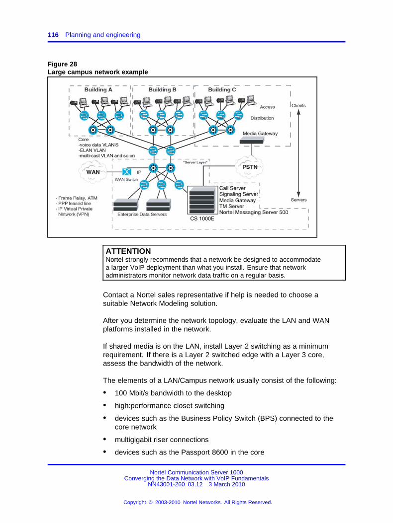
116 Planning and engineering
Figure 28Large campus network example
ATTENTIONNortel strongly recommends that a network be designed to accommodatea larger VoIP deployment than what you install. Ensure that networkadministrators monitor network data traffic on a regular basis.
Contact a Nortel sales representative if help is needed to choose asuitable Network Modeling solution.
After you determine the network topology, evaluate the LAN and WANplatforms installed in the network.
If shared media is on the LAN, install Layer 2 switching as a minimumrequirement. If there is a Layer 2 switched edge with a Layer 3 core,assess the bandwidth of the network.
The elements of a LAN/Campus network usually consist of the following:
• 100 Mbit/s bandwidth to the desktop
• high:performance closet switching
• devices such as the Business Policy Switch (BPS) connected to thecore network
• multigigabit riser connections
• devices such as the Passport 8600 in the core
Nortel Communication Server 1000Converging the Data Network with VoIP Fundamentals
NN43001-260 03.12 3 March 2010
Copyright © 2003-2010 Nortel Networks. All Rights Reserved.
.

Network design assessment 117
These campus networks require only the simplest QoS mechanisms.These types of devices can take advantage of DiffServ from end:to:end.
If VoIP traffic travels on the WAN, high bandwidth can be achieved withnetworks connected through high:speed point:to:point Digital SignalLevel 3 (DS3) links or through ATM/SONET services of Optical Carrier 3(OC:3) and higher. All:optical networks with gigabit Ethernet also providehigh:bandwidth transport.
Campus platforms Document the platforms used in the campus and thefollowing information for each switch:
• vendor
• switch model number
• hardware versions
• software versions
Typically, campus networks should be designed with high:bandwidth edgeswitches with multi:gigabit Ethernet connections to a switched Layer 3 IPnetwork.
Riser access links and Layer 3 capacity are critical areas. If the desktopswitching platform provides 24 connections at 100 Mbit/s and has onlyfour 100 Mbit/s links, a significant bottleneck can occur at the riser.Serialization and queueing delays can become an issue that requires theapplication of QoS mechanisms, such as 802.1Q/802.1p and/or DiffServ.
Nortel recommends migrating 100 Mbit/s riser links to Gigabit Ethernet.
ATTENTIONAll VoIP servers and IP Phones must be connected to Layer 2 switches.
Shared:media hubs are not supported.Shared:media hubs are low bandwidthdevices and do not support QoS mechanisms.
Application requirementsTable 16 "Common application performance parameters" (page 118) liststhe various QoS performance parameters required by some commonapplications. If these parameters are mixed over a common:use IPnetwork and QoS technologies are not used, the traffic can experienceunpredictable behavior.
Nortel Communication Server 1000Converging the Data Network with VoIP Fundamentals
NN43001-260 03.12 3 March 2010
Copyright © 2003-2010 Nortel Networks. All Rights Reserved.
.

118 Planning and engineering
Table 16Common application performance parameters
Sensitivity to
Application
Relativebandwidth
demand Delay JitterPacketLoss
VoIP Low High High High
Video Conferencing High High High Med
Streaming Video on Demand High Med Med Med
Streaming Audio Low Med Med Med
Web browsing (eBusiness) Med Med Low High
E:mail Low Low Low High
File Transfer Med Low Low High
Link speedsLink speeds in a WAN environment are usually low compared to a LAN.When you consider VoIP in a WAN environment, link speeds under 1Mbit/s result in the serialization delay of VoIP packets, which can impairdeployment. When small VoIP packets travel over a network that typicallyinclude packet sizes up to 1500 bytes, these larger packets introducevariable delay (jitter) in the network. This impacts voice quality.
To address delay on a WAN, implement the following:
• protocol prioritization
• traffic shaping (for Frame Relay)
• DiffServ
• fragmentation and interleaving (larger packet sizes incur higherserialization delays and introduce jitter into the VoIP stream)
Other vendor devices include alternative mechanisms..
If link speed and packet size are considered, the serialization delayintroduced can be predicted. For more information, see “Serializationdelay” (page 150) .
ATTENTIONNortel strongly recommends that you begin with an MTU size of 232 bytes forlinks under 1 Mbit/s, and adjust upwards as needed.
Some applications do not perform well with an adjusted MTU, so caution mustbe used when utilizing MTU.
Nortel Communication Server 1000Converging the Data Network with VoIP Fundamentals
NN43001-260 03.12 3 March 2010
Copyright © 2003-2010 Nortel Networks. All Rights Reserved.
.

Network design assessment 119
Link typesIdentify and document the link types used in the network. A number ofdifferent link types are available in the network and each can have animpact on VoIP.
A typical campus network can have 100 Mbit/s of bandwidth going to thedesk, with multi:gigabit riser links. Because bandwidth is plentiful, peaklink utilization is the most important issue. If link utilization is averaged, itmay not be accurate. A minimum of Layer 2 switching is required, withno shared media.
Point:to:Point links (PPP)Point:to:Point (PPP) links are direct point:to:point links, and give thenetwork operator maximum control over QoS. PPP links provide dedicatedbandwidth and flexible termination points.
Frame RelayFrame Relay (FR) networks provide flexibility when the requirementsinclude a full meshed topology. The FR networks have a lower overallcost, with respect to meshed designs.
Frame Relay networks are based on a shared:access model, where DataLink Connection Identifier (DLCI) numbers are used to define PermanentVirtual Circuits (PVCs) in the network.
QoS in a Frame Relay network is achieved by specifying a CommittedInformation Rate (CIR) and using separate PVC’s. CIR is the level of datatraffic (in bits) that the carrier agrees to handle, averaged over a periodof time.
The CIR on the voice traffic PVC must be set for the total peak traffic,because any traffic that exceeds the CIR is marked Discard Eligible (DE)and can be dropped by the carrier. This is not an acceptable conditionfor VoIP traffic, as real:time data carrying packetized voice cannot beretransmitted.
Ensure you understand the design of the carrier network, how much trafficis currently being transported, and if any type of Service Level Agreement(SLA), other than CIR, is offered.
The WAN:access platform in the network can help ensure that VoIPtraffic does not exceed the CIR on the PVC. Protocol prioritization, trafficshaping, and fragmentation can insure that the VoIP traffic is transmittedfirst and does not exceed the CIR on the PVC.
Nortel Communication Server 1000Converging the Data Network with VoIP Fundamentals
NN43001-260 03.12 3 March 2010
Copyright © 2003-2010 Nortel Networks. All Rights Reserved.
.

120 Planning and engineering
Asynchronous Transfer ModeAsynchronous Transfer Mode (ATM) can provide a Constant Bit Rate(CBR) service, by dedicating a channel with a fixed bandwidth based onthe applications needs.
Using ATM as a transport for VoIP adds overhead associated with ATM. AG.711 codec with 20 millisecond (ms) voice payload, when the associatedTCP, UDP, and RTP header information is added, can become a 200:byteframe.
Using ATM for transport requires that you segment the frame to fit intomultiple cells. This adds an additional 10 to 15 percent of overhead. TheG.729 codec significantly reduces the frame size to 60 bytes, so codecselection is crucial for the WAN.
Virtual Private NetworkA Virtual Private Network (VPN) uses the public telecommunicationinfrastructure, such as the Internet, to provide remote offices or individualusers with secure access to their organization’s network. Encryption andother security mechanisms are used to ensure that only authorized userscan access the network and that the data cannot be intercepted.
For more information about security management, see SecurityManagement (NN43001-604) ().
Link utilization assessmentTo support VoIP over WAN links, it is important to assess link utilization.There are several ways to gather statistical information on a WAN link.Tools, such as an existing network management system, should have theability to poll routers through SNMP and collect the statistics over a periodof time about use of a given WAN link.
Other methods of assessment include the use of imbedded RemoteMonitoring (RMON) and external RMON probes installed to gatherstatistical information, including link utilization.
Over low:bandwidth connections, the amount of VoIP traffic should belimited to a percentage of the bandwidth of the connection. Use the limitto minimize the maximum queueing delay that the VoIP traffic experiencesover low:bandwidth connections.
Nortel Communication Server 1000Converging the Data Network with VoIP Fundamentals
NN43001-260 03.12 3 March 2010
Copyright © 2003-2010 Nortel Networks. All Rights Reserved.
.

Network design assessment 121
When you use distributed or survivable media gateways, ensure youmonitor and reengineer the link utilization on a regular basis. Forinformation about estimating ELAN traffic, see the following documents:
• Communication Server 1000M and Meridian 1 Small System Planningand Engineering (NN43011-220) ()
• Communication Server 1000M and Meridian 1 Large System Planningand Engineering (NN43021-220) ()
• Communication Server 1000E Planning and Engineering(NN43041-220) ()
For more information about Bandwidth Management of VoIP calls, see“VoIP Bandwidth Management zones” (page 70).
Assess link useWAN links are the highest repeating expenses in the network and theyoften cause capacity problemsk. Unlike LAN bandwidth, which is virtuallyfree and easily implemented, WAN links take time to finance, provision,and upgrade, especially inter:LATA (Local Access and Transport Area)and international links. For these reasons, it is important to determine thestate of WAN links in the intranet before you install the network.
ATTENTIONThe use of QoS mechanisms that prioritize voice over data traffic effectivelyincreases the amount of bandwidth available to voice traffic.
Perform the following steps to assess the link utilization.
Assessing link utilization
Step Action
1 Obtain a current topology map and link utilization report of theintranet.
2 Visually inspect the topology map to reveal which WAN links arelikely to deliver IP Line traffic, alternately, use the Traceroute tool(see “Network performance measurement tools” (page 128)).
3 Determine the current utilization of the WAN links and note thereporting window that appears in the link utilization report.
For example, link use can be averaged over a week, a day, oran hour.
4 Obtain the busy period (peak hour) use of the link.
5 As WAN links are full:duplex and data services exhibitasymmetric traffic behavior, obtain the utilization of the linkrepresenting traffic flowing in the heavier direction.
Nortel Communication Server 1000Converging the Data Network with VoIP Fundamentals
NN43001-260 03.12 3 March 2010
Copyright © 2003-2010 Nortel Networks. All Rights Reserved.
.

122 Planning and engineering
6 Assess how much spare capacity is available.
Enterprise intranets are subject to capacity planning policies thatensure capacity usage remains below a predetermined level.
For example, a planning policy states that the use of a 56 kbit/slink during the peak hour must not exceed 50%; for a T1 link, thethreshold is higher, perhaps 80%. The carrying capacity of the56 kbit/s link is 28 kbit/s, and for the T1 link is 1.2288 Mbit/s. Insome organizations, the thresholds can be lower than that usedin this example; in the event of link failures, there needs to bespare capacity for traffic to be rerouted.
7 Obtain the QoS parameters (in addition to the physical linkcapacity), especially the Committed Information Rate (CIR) forFrame Relay and Maximum Cell Rate (MCR) for ATM.
Some WAN links can be provisioned on top of Layer 2 services,such as Frame Relay and ATM; the router:to:router link isactually a virtual circuit, which is subject to a physical capacityand a logical capacity limit.
8 The difference between the current capacity, and its allowablelimit, is the available VoIP capacity.
For example, a T1 link used at 48% during the peak hour, witha planning limit of 80%, has an available capacity of about 492kbit/s.
--End--
Traffic flows in the networkIdentify traffic flows in the network by using an existing NetworkManagement System (NMS) or another passive tool, such as a packetsniffer. These tools identify protocol distribution in the network and trafficflow between devices. RMON probes and devices with embedded RMONcapability can also help the network designer determine where traffic flowsoccur.
Assess traffic flows over a period of time (a week or longer depending onthe complexity of the network). Observe the peak times of the day, theweek, and the month to determine the highest periods of use.
After traffic flows are identified, determine bandwidth requirements usingtools such as a VoIP bandwidth calculator. Ask your Nortel representativefor the VoIP bandwidth calculator spreadsheet. For more information, see“VoIP Bandwidth Demand Calculator” (page 140) .
Nortel Communication Server 1000Converging the Data Network with VoIP Fundamentals
NN43001-260 03.12 3 March 2010
Copyright © 2003-2010 Nortel Networks. All Rights Reserved.
.

Network design assessment 123
Available traffic toolsThere are many tools available to assess network traffic, such as:
• Traceroute
• Call Detail Record
• Traffic study
• Network Diagnostic Utilities (see “Network Diagnostic Utilities” (page232).)
Traceroute Traceroute uses the IP TTL (time:to:live) field to determinerouter hops to a specific IP address. A router must not forward an IPpacket with a TTL field of 0 or 1. The router must instead throw away thepacket and return to the originating IP address an ICMP time exceededmessage. Traceroute uses the message by sending an IP datagram with aTTL of 1 to the specified destination host.
The first router to handle the datagram sends back a time exceededmessage. This identifies the first router on the route. Traceroute thensends out a datagram with a TTL of 2, which causes the second routeron the route to return a time exceeded message (and so on) until allhops have been identified. The traceroute IP datagram has a UDP Portnumber unlikely to be in use at the destination (usually > 30 000), whichcauses the destination to return a port unreachable ICMP packet, therebyidentifying the destination host.
Traceroute can be used to measure roundtrip times to all hops along aroute, thereby identifying bottlenecks in the network.
Call Detail Record Obtain a Call Detail Record (CDR) to locate the VoIPtraffic flows in the network. The CDR can help identify the network routesthat VoIP will use.
The peak values for time of day, day of week, and day of month must beconsidered to ensure consistent voice quality.
For more information, see Call Detail Recording Fundamentals(NN43001-550) ().
Traffic study Traffic is a measurement of specific resource activity level.LD 02 has been reserved to schedule and select the traffic study options.
Nortel Communication Server 1000Converging the Data Network with VoIP Fundamentals
NN43001-260 03.12 3 March 2010
Copyright © 2003-2010 Nortel Networks. All Rights Reserved.
.

124 Planning and engineering
A network traffic study provides information, such as:
• the amount of call traffic on each choice in each route list
• the number of calls going out on expensive routes in each route list
• queueing activity (off:hook queueing and call:back queueing) and thelength of time users queue on average
For more information about traffic studies, see the following resources:
• Traffic Measurement Formats and Output Reference (NN43001-750) ()
• LD 02 in Software Input Output Reference — Administration(NN43001-611) ()
Service level agreementsAs part of a service level agreement, the service provider shouldguarantee a certain amount of bandwidth.
Whether a home user on a cable or DSL connection, or a large networkcustomer using Frame Relay, the service provider must guaranteebandwidth for VoIP.
Guaranteed bandwidth in Frame Relay, for example, is known asCommitted Information Rate (CIR). The guaranteed bandwidth must besufficient to accommodate all of the network traffic. Ensure that the CIRrate contracted is received when you lease a connection.
Exercise caution if service level agreements are not available.
Network planningPerform the following actions before you configure BandwidthManagement in a Communication Server 1000 network:
• Main Office and Branch Office need to have the same VPNI settingto ensure correct bandwidth management control by the Main Office.Another reason to have the same VPNI setting across call servers isto support bandwidth management for Network Wide Virtual Office(NWVO). Also, two systems within the same LAN would require thesame VPNI setting to ensure INTRAZONE call treatment.
• Choose unique Bandwidth zone numbers for all Call Servers in thenetwork to use when configuring the endpoints (telephones andgateways) on the Call Server.
• Choose the same zone number for Virtual trunk resources for all Callservers within the same network (for example, Main Office and BranchOffice configuration or MG 1000B groups or call servers within oneLAN).
Nortel Communication Server 1000Converging the Data Network with VoIP Fundamentals
NN43001-260 03.12 3 March 2010
Copyright © 2003-2010 Nortel Networks. All Rights Reserved.
.

Network Performance Measurement 125
• Choose the codecs to enable on each Call Server.
• Identify the interzone codec strategy (BB or BQ) for each zone in thenetwork.
• Identify the intrazone codec strategy (BB or BQ) for each zone in thenetwork.
• Calculate the bandwidth available for intrazone calls for each zone inthe network.
• Calculate the available bandwidth for interzone calls for each zone inthe network.
• Calculate the available bandwidth for intrazone calls.
CAUTIONService InterruptionIf the network is planned so IP Phones use a different routeto the main office than the MG 1000B Terminal Proxy Server(TPS), a fault condition can occur. When the MG 1000B TPScan ping the main office but the IP Phone cannot ping the mainoffice due to a network outage, an IP Phone registration canforce the telephone into a cycle of registering locally, beingredirected to the main office, rebooting and then registeringlocally again. When this cycle occurs, further diagnose thenetwork outage.
Network Performance MeasurementThis section describes the criteria required to achieve excellent voicequality.
Performance criteriaTo achieve excellence in voice quality you need the following elements:
• a properly:engineered network
• good network equipment and redundancy
• adequate bandwidth for peak usage
• use of QoS mechanisms
• ongoing monitoring and maintenance
If the previous elements are not present, VoIP performance suffers.
The network should also meet the following specifications:
• End:to:end packet delay: Packet delay is the point:to:point, one:waydelay between the time a packet is sent to the time it is received atthe remote end. It is comprised of delays at the Voice Gateway MediaCard, Internet Telephone, and the IP network. To minimize delays, the
Nortel Communication Server 1000Converging the Data Network with VoIP Fundamentals
NN43001-260 03.12 3 March 2010
Copyright © 2003-2010 Nortel Networks. All Rights Reserved.
.

126 Planning and engineering
IP Telephony node and Internet Telephonemust be located to minimizethe number of hops to the network backbone or WAN.
ATTENTIONNortel recommends an end:to:end delay of <= 50 ms on the IP network toensure good voice quality. The 50 ms does not include the built:in delay ofthe Voice Gateway Media Card and IP Phone.
• End:to:end packet loss: Packet loss is the percentage of packetssent that do not arrive at their destination. Transmission equipmentproblems, packet delay, and network congestion cause packet loss. Invoice conversation, packet loss appears as gaps in the conversation.Sporadic loss of a few packets can be more tolerable than infrequentloss of a large number of packets clustered together.
ATTENTIONFor high:quality voice transmission, the long:term average packet lossbetween the IP Phones and the Voice Gateway Media Card TLAN networkinterface must be < 1%, and the short:term packet loss must not exceed5% in any 10:second interval.
ATTENTIONNortel strongly recommends that you use the G.711 codec with the followingconfiguration:
• end:to end delay less than 150 ms one way (network delay +packetization delay + jitter buffer delay < 150)
• packet loss less than 0.5% (approaching 0%)
• maximum jitter buffer setting for IP Phone as low as possible (maximum100 ms)
Packet loss on the ELAN network interface can cause
— communication problems between the Call Server and the VoiceGateway Media Cards
— lost SNMP alarms
— incorrect status information on the TM console
— other signaling:related problems
ATTENTIONBecause the ELAN network is a Layer 2 Switched LAN, the packet lossmust be zero. If packet loss is experienced, its source must be investigatedand eliminated. For reliable signaling communication on the ELAN networkinterface, the packet loss must be < 1%.
Nortel Communication Server 1000Converging the Data Network with VoIP Fundamentals
NN43001-260 03.12 3 March 2010
Copyright © 2003-2010 Nortel Networks. All Rights Reserved.
.

Network Performance Measurement 127
Proactive Voice Quality managementProactive Voice Quality management (PVQ) allows the user to monitor thevoice quality of Voice over Internet Protocol (VoIP) calls on an ongoingbasis and detect specific problems when they occur. Alarms and trafficreports are used to implement this.
Four metrics on voice quality are collected on every call: packet loss,latency, jitter, and R:value. The metrics are analyzed to determine if analarm should be generated. The metrics are also aggregated and reported,along with other information, in Traffic Report 16.
The R:level metric is calculated only for those IP Phones equipped with afirmware version of 2.0 or higher.
A PVQ alarm is generated whenever a metric exceeds a given threshold.The thresholds are user:defined in LD 117 at a Call Server and propagatethroughout the system. Listed in order of increasing severity, the thresholdlevels include: good, warning, and unacceptable.
The following types of PVQ alarms exist:
• Alarms generated on a per:zone basis (zone:based) — generated ifthe aggregate metrics for a particular zone, such as a branch office,exceeds a warning or unacceptable threshold. These alarms aregenerated by the Call Server.
• Alarms generated on a per:call basis — each call is monitored andan alarm generated if any metric meets or exceeds a warning orunacceptable threshold. These alarms are generated by the SignalingServer.
The user can set a Notification Level to control when and how oftenan alarm is generated. This capability is useful when many alarms aregenerated, but most are minor and relate to potential system capacityissues rather than voice quality. It is also useful when a user wants tomonitor a particular area of a network, such as a branch office. Notificationlevels are defined in LD 117.
Nortel Communication Server 1000Converging the Data Network with VoIP Fundamentals
NN43001-260 03.12 3 March 2010
Copyright © 2003-2010 Nortel Networks. All Rights Reserved.
.

128 Planning and engineering
Network performance measurement toolsPing and traceroute are standard IP tools that are usually included with anetwork host TCP/IP stack. QoS measurement tools and packages arecommonly available that include delay monitoring tools, which includefeatures like timestamping, plotting, and computation of standard deviation.For information about network performance measurement tools, see
• “QoS monitoring and reporting tools” (page 232)
• “Proactive Voice Quality management” (page 127)
• IP Phones Fundamentals (NN43001-368)
The following measuring tools are based on the Internet ControlMessaging Protocol (ICMP):
• Ping — sends ICMP echo requests
• Traceroute — sends packets to unequipped port numbers andprocesses to create ICMP destination unavailable messages
Both ping and traceroute are basic measuring tools that can be usedto assess the IP Line network and are standard utilities that comewith most commercial operating systems. Ping is used to measure theround:trip delay of a packet and the percentage of packet loss. Traceroutebreaks down delay segments of a source:destination pair and any hopsin:between to accumulate measurements.
There are several third:party applications that perform data collectionsimilar to ping and traceroute, but also analyze data and plot performancecharts. The use of ping and traceroute to collect data for manual analysisis labor intensive; however, they provide information as useful as the moresophisticated applications.
The following network performance evaluation overview assumes thatthe ping program is available on a PC, or a network management toolis available to collect delay and loss data and to access the LAN thatconnects to the router to the intranet.
Evaluating network performance
Step Action
1 Use ping or an equivalent tool to collect round:trip delay (in ms)and loss (in%) data.
2 Divide the delay (determined in step 1) by 2 to approximateone:way delay and add 93 ms to adjust for ITG processing andbuffering time.
Nortel Communication Server 1000Converging the Data Network with VoIP Fundamentals
NN43001-260 03.12 3 March 2010
Copyright © 2003-2010 Nortel Networks. All Rights Reserved.
.

Network Performance Measurement 129
3 Use a QoS chart, or Table 31 "QoS levels" (page 168), to predictthe QoS categories: Excellent, Good, Fair or Poor.
4 If a customer wants to manage the QoS in a more detailedfashion, rebalance the values of delay compared to loss byadjusting system parameters, such as preferred codec, payloadsize, and routing algorithm, to move the resulting QoS amongdifferent categories.
5 If the QoS objective is met, repeat the process periodically tomake sure the required QoS is maintained.
--End--
Network availabilityNetwork availability has the most significant effect on QoS. If the networkis unavailable, even for brief periods of time, the user or application canachieve unpredictable or undesirable performance levels.
Network availability is dependent on the availability of a survivable,redundant network. A redundant network should include the followingelements to ensure survivability:
• redundant devices, such as
— interfaces
— processor cards
— power supplies in routers and switches
• resilient networking protocols
• multiple physical connections, such as copper or fiber
• backup power sources
Media SecurityMedia Security enables two endpoints capable of Secure Real:TimeTransport Protocol (SRTP) connections to engage in secure mediaexchanges. For calls that pass over IP systems only, Media Security canprovide end:to:end encryption of the call if both endpoints can supportSRTP connections. If you configure Media Security to use the MediaSecurity Always CoS, it blocks any calls that cannot be encrypted.
Nortel Communication Server 1000Converging the Data Network with VoIP Fundamentals
NN43001-260 03.12 3 March 2010
Copyright © 2003-2010 Nortel Networks. All Rights Reserved.
.
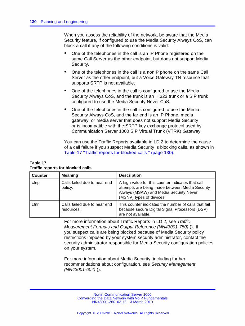
130 Planning and engineering
When you assess the reliability of the network, be aware that the MediaSecurity feature, if configured to use the Media Security Always CoS, canblock a call if any of the following conditions is valid:
• One of the telephones in the call is an IP Phone registered on thesame Call Server as the other endpoint, but does not support MediaSecurity.
• One of the telephones in the call is a nonIP phone on the same CallServer as the other endpoint, but a Voice Gateway TN resource thatsupports SRTP is not available.
• One of the telephones in the call is configured to use the MediaSecurity Always CoS, and the trunk is an H.323 trunk or a SIP trunkconfigured to use the Media Security Never CoS.
• One of the telephones in the call is configured to use the MediaSecurity Always CoS, and the far end is an IP Phone, mediagateway, or media server that does not support Media Securityor is incompatible with the SRTP key exchange protocol used byCommunication Server 1000 SIP Virtual Trunk (VTRK) Gateway.
You can use the Traffic Reports available in LD 2 to determine the causeof a call failure if you suspect Media Security is blocking calls, as shown inTable 17 "Traffic reports for blocked calls " (page 130).
Table 17Traffic reports for blocked calls
Counter Meaning Description
cfnp Calls failed due to near endpolicy.
A high value for this counter indicates that callattempts are being made between Media SecurityAlways (MSAW) and Media Security Never(MSNV) types of devices.
cfnr Calls failed due to near endresources.
This counter indicates the number of calls that failbecause secure Digital Signal Processors (DSP)are not available.
For more information about Traffic Reports in LD 2, see TrafficMeasurement Formats and Output Reference (NN43001-750) (). Ifyou suspect calls are being blocked because of Media Security policyrestrictions imposed by your system security administrator, contact thesecurity administrator responsible for Media Security configuration policieson your system.
For more information about Media Security, including furtherrecommendations about configuration, see Security Management(NN43001-604) ().
Nortel Communication Server 1000Converging the Data Network with VoIP Fundamentals
NN43001-260 03.12 3 March 2010
Copyright © 2003-2010 Nortel Networks. All Rights Reserved.
.

Network Performance Measurement 131
Set QoS expectationsThe users of corporate voice and data services expect these services tomeet some perceived Quality of Service (QoS) that influences networkdesign. The goal is to design and allocate enough resources in thenetwork to meet the needs of the users. QoS metrics or parameters arewhat quantifies the needs of the user of the service.
In the context of a Meridian 1 and CS 1000M system, Figure 29 "QoSparameters" (page 131) shows the relationship between users andservices.
Figure 29QoS parameters
In Figure 29 "QoS parameters" (page 131), consider the following twointerfaces:
• The Meridian 1, including the IP Trunk 3.0 (or later) nodes, interfaceswith the end users. Voice services offered by the Meridian 1 must meetuser:oriented QoS objectives.
• The IP Trunk 3.0 (or later) nodes interface with the intranet. Theservice provided by the intranet is best:effort delivery of IP packets,not guarantee QoS for real:time voice transport. IP Trunk 3.0 (or later)translates the QoS objectives set by the end:users into IP:oriented
Nortel Communication Server 1000Converging the Data Network with VoIP Fundamentals
NN43001-260 03.12 3 March 2010
Copyright © 2003-2010 Nortel Networks. All Rights Reserved.
.

132 Planning and engineering
QoS objectives. The guidelines call these objectives intranet QoSobjectives.
The QoS level is a user:oriented QoS metric that takes one of four settings– Excellent, Good, Fair, or Poor – that indicate the quality of voice service.IP Trunk 3.0 (or later) periodically calculates the prevailing QoS level persite pair, based on measurement of the following:
• one:way delay
• packet loss
• codec
ATTENTIONNortel strongly recommends that G.711 codec be used over high:bandwidthconnections, and used any time that call quality is high priority. Where callquality is high priority, sufficient bandwidth must be provided for the VoIPapplication. The Best Quality (BQ) codec is usually chosen and configured asG.711 within the zone configuration (intrazone).
Use the G.729 codec to compress voice traffic over low:bandwidth connectionswhen bandwidth considerations take precedence over call quality. The BestBandwidth (BB) codec is usually chosen and set to G.729A or G.729AB betweenzones (interzone).
Codec details are then configured on the Signaling Server through TM orCommunication Server 1000 Element Manager.
Figure 30 "QoS levels with G.729A/AB codec" (page 133), Figure 31 "QoSlevel with G.711 codec" (page 134), and Figure 32 "QoS level with G.723codec" (page 135) are derived from the ITU:T G.107 Transmission RatingModel. These diagrams show the operating regions in terms of one:waydelay and packet loss for each codec. Note that among the codecs, G.711A:law/G.711 mu:law delivers the best quality for a given intranet QoS,followed by G.729AB, G.723.1 6.4 kbit/s, and G.723.1 5.3 kbit/s. Thesegraphs determine the delay and error budget for the underlying intranet soit delivers a required quality of voice service.
Fax is more susceptible to packet loss than is the human ear, inthat quality starts to degrade when packet loss exceeds 4%. Nortelrecommends that fax services be supported with IP Trunk 3.0 (or later)that operates at the Excellent or Good QoS level. Avoid offering faxservices between two sites that can guarantee no better than a Fair orPoor QoS level.
G.729AB codecThe G.729 uses less bandwidth than the G.711. If minimizing bandwidthdemand is a priority, and the customer is willing to accept lesser voicequality, a G.729AB codec can be used.
Nortel Communication Server 1000Converging the Data Network with VoIP Fundamentals
NN43001-260 03.12 3 March 2010
Copyright © 2003-2010 Nortel Networks. All Rights Reserved.
.

Network Performance Measurement 133
Extreme care must be taken in the network design if using the G.729ABcodec. The G.729AB codec has the same requirements as the G.711codec.
Figure 30 "QoS levels with G.729A/AB codec" (page 133) shows the QoSlevels with a G.729A/AB codec.
Figure 30QoS levels with G.729A/AB codec
G.711 codecNortel recommends that you use the G.711 codec.
Figure 31 "QoS level with G.711 codec" (page 134) shows the QoS levelswith a G.711 codec.
Nortel Communication Server 1000Converging the Data Network with VoIP Fundamentals
NN43001-260 03.12 3 March 2010
Copyright © 2003-2010 Nortel Networks. All Rights Reserved.
.

134 Planning and engineering
Figure 31QoS level with G.711 codec
G.723 codecFigure 32 "QoS level with G.723 codec" (page 135) shows the QoS levelswith a G.723 codec.
Nortel Communication Server 1000Converging the Data Network with VoIP Fundamentals
NN43001-260 03.12 3 March 2010
Copyright © 2003-2010 Nortel Networks. All Rights Reserved.
.

Network Performance Measurement 135
Figure 32QoS level with G.723 codec
BandwidthBandwidth is the most significant parameter that affects QoS. There aretwo types of bandwidth:
• Available Bandwidth
• Guaranteed Bandwidth
ATTENTIONThe use of QoS mechanisms that prioritize voice over data traffic effectivelyincreases the amount of available bandwidth to voice traffic.
Available BandwidthMany network operators oversubscribe the bandwidth on their network tomaximize the return on their network infrastructure or leased bandwidth.
Oversubscribing bandwidth means that the bandwidth a user subscribesto is not always available. All users compete for Available Bandwidth. Theamount of bandwidth available to a user depends on the amount of trafficfrom other network users at any given time.
Guaranteed BandwidthSome network operators offer a service that guarantees a minimumbandwidth and burst bandwidth in the Service Level Agreement (SLA).This service is more expensive than the Available Bandwidth service. The
Nortel Communication Server 1000Converging the Data Network with VoIP Fundamentals
NN43001-260 03.12 3 March 2010
Copyright © 2003-2010 Nortel Networks. All Rights Reserved.
.

136 Planning and engineering
network operator must ensure that the Guaranteed Bandwidth subscribersget preferential treatment (QoS bandwidth guarantee) over the AvailableBandwidth subscribers.
This can be accomplished in several ways. Sometimes, the networkoperator separates the subscribers by different physical or logicalnetworks, such as Virtual Local Area Networks (VLANs) or Virtual Circuits.
In other cases, the Guaranteed Bandwidth traffic shares the sameinfrastructure as the Available Bandwidth traffic. This is often seen wherenetwork connections are expensive, or where the bandwidth is leased fromother service providers. When both types of subscribers share the sameinfrastructure, the network must prioritize Guaranteed Bandwidth trafficover Available Bandwidth traffic. This ensures that when network traffic isheavy, the Guaranteed Bandwidth subscriber SLA is met.
QueueingOver:engineering network bandwidth does not necessarily solve voicequality problems, as IP network traffic is inherently bursty in nature. Atany time, a burst of packets can enter a switch. If the number of packetsreceived in that instant is greater than the capacity of the queue for thetransmitting port, then packets are lost. This situation is particularly seriouson slow connections.
If a queue is busy (though not necessarily full), voice packet traffic canback up and jitter can occur if voice packets are not prioritized. NetworkQoS mechanisms are based on assigning different priorities to multiplequeues. A voice queue is assigned a higher priority. If a specific queue isassigned only to voice traffic, then there is less chance that voice packetsare discarded because the queue is too full. Network delay is reduced,as voice packets are transmitted first to minimizes delay, jitter, and loss.Perceived voice quality is greatly improved.
Calculating per:call bandwidthCalculating VoIP traffic requirements You must forecast the hundredsof call seconds for each hour (CCS) of traffic that the CS 1000 andMeridian 1 systems processes through the IP Line network. CCS trafficgenerated by an IP Phone is similar to that of a digital telephone. Theprocedures in this section calculate the bandwidth required to supportgiven amounts of traffic.
• determine the CCS/CCS rating of IP Phone
For more information, see Communication Server 1000M and Meridian1 Large System Planning and Engineering (NN43021-220) ().
• determine the number of IP Phones
Nortel Communication Server 1000Converging the Data Network with VoIP Fundamentals
NN43001-260 03.12 3 March 2010
Copyright © 2003-2010 Nortel Networks. All Rights Reserved.
.

Network Performance Measurement 137
• determine the number of subnets/servers accessed by the IP Phones
Base all traffic data on busy hour requirements.
• calculate total LAN bandwidth requirement
• calculate WAN bandwidth requirement for each subnet or server/router
• consider the impact of incremental IP Line traffic on routers and LANresources in the intranet. LAN segments can become saturated, androuters can experience high CPU use. Consider rerouting scenarios ina case where a link is down.
Calculating LAN traffic To calculate the total LAN requirement, total allsources of traffic destined for the Internet Telephony network using thesame LAN.
Use the following procedures to calculate LAN traffic:
Calculating LAN traffic
Step Action
1 Add the following items to calculate the total subnet traffic (inErlangs):
• number of IP Phones x (CCS ÷ CCS rating)
• number of voice gateways on the Voice Gateway Media Card
• number of WAN connections
ATTENTIONEach source of traffic has a different CCS rating. Calculate thesubnet traffic for each source of traffic and add the amounts for thetotal.
2 Use the number of Erlangs to calculate the equivalent number oflines by using the calculator at the following Web site:
www.erlang.com/calculator/erlb
Assume a blocking factor of 1% (0.010).
3 Find the LAN bandwidth usage (kbit/s) in based on the codecused for the traffic source.
4 Calculate the bandwidth of a subnet using the followingcalculation:
Subnet bandwidth = Total number of lines × LAN bandwidthusage
5 Repeat Step 1 to Step 4 for each subnet.
Nortel Communication Server 1000Converging the Data Network with VoIP Fundamentals
NN43001-260 03.12 3 March 2010
Copyright © 2003-2010 Nortel Networks. All Rights Reserved.
.

138 Planning and engineering
6 Calculate the total LAN traffic by adding the total bandwidth foreach subnet calculation.
--End--
LAN engineering example The following example calculates LANbandwidth assuming half:duplex links.
Using G.729AB 30 ms, LAN bandwidth usage is 57.6 kbit/s.
The formula is:
Number of Erlangs = Number of IP Phones × (CCS ÷ 36)
Calculating LAN bandwidth example
Step Action
1 Subnet A: 28 Internet Telephones, average 6 CCS ÷ IP Phone
Subnet A total Erlangs = 28 × 6 ÷ 36 = 4.66Subnet A bandwidth = 4.66 × 57.6 kbit/s = 268.4 kbit/s
2 Subnet B: 72 IP Phones, average 5 CCS ÷ Internet Telephone
Subnet B total Erlangs = 72 × 5 ÷ 36 = 10Subnet B bandwidth = 10 × 57.6 = 576 kbit/s
3 Subnet C: 12 IP Phones, average 6 CCS ÷ IP Phone
Subnet C total Erlangs = 12 × 6 ÷ 36 = 2Subnet C bandwidth = 2 × 57.6 = 115.2 kbit/s
4 Calculate the LAN Bandwidth by finding the sum of all subnetbandwidths:
LAN Bandwidth = 268.4 + 576 + 115.2 = 959.6 kbit/s
--End--
WAN traffic calculations For data rate requirements for the intranetroute, calculation is based on duplex channels. The data rate for a WANis the duplex data rate. For example, 128 kbit/s on the LAN is equal toa 64 kbit/s duplex channel on the WAN. Use the following procedure tocalculate data rate requirements for the intranet route. The effects ofReal:time Transport Protocol (RTP) header compression by the routerare not considered in these calculations but must be included whereapplicable.
Use the following steps to calculate WAN traffic.
Nortel Communication Server 1000Converging the Data Network with VoIP Fundamentals
NN43001-260 03.12 3 March 2010
Copyright © 2003-2010 Nortel Networks. All Rights Reserved.
.

Network Performance Measurement 139
Calculating WAN traffic
Step Action
1 Calculate the total subnet traffic using the following formula:
Total subnet traffic = Number of IP Phones x CCS/InternetTelephone.
2 Convert to Erlangs:
Total CCS / 36 (on the half:duplex LAN)
3 Find WAN bandwidth usage (kbit/s) from the WAN BaseBandwidth columns.
4 Calculate bandwidth for each subnet = Total Erlangs x WANbandwidth usage.
5 Multiply bandwidth of each subnet by 1.3 to adjust for trafficpeaking.
6 Repeat the procedure for each subnet.
7 Adjust WAN bandwidth to account for WAN overhead dependingon the WAN technology used:
• ATM (AAL1): multiply subnet bandwidth x 1.20 (9 bytesoverhead/44 bytes payload)
• ATM (AAL5): multiply subnet bandwidth x 1.13 (6 bytesoverhead/47 bytes payload)
• Frame Relay: multiply subnet bandwidth x 1.20 (6 bytesoverhead/30 bytes payload – variable payload up to 4096bytes)
ATTENTIONEach WAN link must be engineered to be no more than 80% of itstotal bandwidth if the bandwidth is 1536 kbit/s or higher (T1 rate). Ifthe rate is lower, up to 50% loading on the WAN is recommended.
--End--
WAN engineering example The following is an example of calculatingthe WAN bandwidth.
Calculating LAN bandwidth example
Step Action
1 Subnet A: 36 IP Phones, average 6 CCS/Internet Telephone
Nortel Communication Server 1000Converging the Data Network with VoIP Fundamentals
NN43001-260 03.12 3 March 2010
Copyright © 2003-2010 Nortel Networks. All Rights Reserved.
.

140 Planning and engineering
• Total Erlangs = 36 x 6/36 = 6
• For G.729AB 50 ms, WAN bandwidth usage is 14.4 kbit/s.
• Subnet A WAN bandwidth = 14.4 x 6 = 86.4 kbit/s
• Subnet A WAN bandwidth with 30% peaking= 86.4 x 1.3= 112.32 kbit/s
2 Subnet B: 72 IP Phones, average 5 CCS/IP Phone
• Total Erlangs = 72 x 5/36 = 10
• Subnet B WAN bandwidth = 14.4 x 10 = 144 kbit/s
• Subnet B WAN bandwidth with 30% peaking= 144 x 1.3= 187.2 kbit/s
3 Subnet C: 12 IP Phones, average 6 CCS/IP Phone
• Total Erlangs = 12 x 6/36 = 2
• Subnet C WAN bandwidth = 14.43 x 2 = 28.8 kbit/s
• Subnet C WAN bandwidth with 30% peaking= 28.8 x 1.3= 37.44 kbit/s
4 If the WAN is known to be an ATM network (AAL1), theestimated bandwidth requirements are:
• Subnet A WAN bandwidth with ATM overhead= 112.32 x 1.2= 134.78 kbit/s.
• Subnet B WAN bandwidth with ATM overhead= 187.2 x 1.2= 224.64 kbit/s
• Subnet C WAN bandwidth with ATM overhead= 37.44 x 1.2= 44.93 kbit/s
ATTENTIONBandwidth values can vary slightly depending on the transport type.
--End--
VoIP Bandwidth Demand Calculator The VoIP Bandwidth DemandCalculator is a Microsoft Excel:based tool that quickly determines thebandwidth requirements for a given link.
Nortel Communication Server 1000Converging the Data Network with VoIP Fundamentals
NN43001-260 03.12 3 March 2010
Copyright © 2003-2010 Nortel Networks. All Rights Reserved.
.

Network Performance Measurement 141
The VoIP Bandwidth Demand Calculator uses the following variables:
• number of trunks
• packetization interval
• codec (G.711, G.729, and G.723)
• link type (Frame Relay, PPP, ATM, Ethernet)
• link speed
Ask a Nortel representative for the VoIP Bandwidth Demand Calculatorspreadsheet. Use the parameters in the spreadsheet and the bandwidthcalculator to determine the bandwidth requirement for each client.
Silence Suppression engineering considerationsSilence Suppression/Voice Activity Detection (VAD) results in averagebandwidth savings over time, not immediately. For normal conversations,Silence Suppression creates a 40% savings in average bandwidth used.For example, a single G.729AB voice packet will still consume 30 kbit/s ofbandwidth, but the average bandwidth used for the entire call would beapproximately 23 kbit/s.
Calculate the average bandwidth using the formula:
Codec bandwidth from Table 5 "Bandwidth estimates used by CallAdmission Control" (page 83) x 0.6
When voice services with multichannel requirements are extensively usedin an VoIP network, such as Conference, Music:on:hold, and MessageBroadcasting, additional voice traffic peaks to the IP network generateddue to the simultaneous voice:traffic bursts on multiple channels on thesame links.
Estimate network loading caused by VoIP trafficAn efficient VoIP network design requires an understanding of traffic andthe underlying network that carries the traffic. To determine the networkrequirements of the specific system, the technician must perform thefollowing steps.
Before bandwidth estimation can begin, obtain the following network data:
• A network topology and routing diagram.
• A list of the sites where the Communication Server 1000 Release 5.5nodes are to be installed.
• List the sites with VoIP traffic, and the codec and frame duration(payload) to be used.
Nortel Communication Server 1000Converging the Data Network with VoIP Fundamentals
NN43001-260 03.12 3 March 2010
Copyright © 2003-2010 Nortel Networks. All Rights Reserved.
.

142 Planning and engineering
• Obtain the offered traffic in CCS for each site pair; if available,separate voice traffic from fax traffic (fax traffic sent and received).
• In a network with multiple time zones, use the same real:time busyhour varying actual clock hours at each site that yields the highestoverall network traffic. Traffic to a route is the sum of voice traffic plusthe larger of one:way fax traffic either sent or received.
Determining network requirements
Step Action
1 Estimate the amount of traffic processed by the Meridian 1or Communication Server 1000 system through the IP Linenetwork.
See Communication Server 1000M and Meridian 1: LargeSystem Planning and Engineering (NN43021:220) ().
2 Assess if the existing corporate intranet can adequately supportvoice services.
See “Configuration” (page 249).
3 Organize the IP Line network into zones that represent differenttopographical areas of the network that are separated accordingto bandwidth considerations.
4 Ensure that appropriate QoS measures are implemented acrossthe network to prioritize voice packets over data traffic.
--End--
Example: multinode engineering Table 18 "Example: Traffic flow ina 4:node Communication Server 1000 network" (page 142) summarizestraffic flow of a 4:node Communication Server 1000 network.
Table 18Example: Traffic flow in a 4:node Communication Server 1000 network
Destination Pair Traffic in CCS
Santa Clara/Richardson 60
Santa Clara/Ottawa 45
Santa Clara/Tokyo 15
Richardson/Ottawa 35
Richardson/Tokyo 20
Ottawa/Tokyo 18
Nortel Communication Server 1000Converging the Data Network with VoIP Fundamentals
NN43001-260 03.12 3 March 2010
Copyright © 2003-2010 Nortel Networks. All Rights Reserved.
.

Network Performance Measurement 143
The codec selection is on a per:call basis. During call setup negotiation,only the type of codec available at both destinations is selected. Whenno agreeable codec is available at both ends, the default codec G.711 isused.
For this example, assume that the preferred codec to handle VoIP callsin this network is G.729AB.
Table 19 "Example: Incremental WAN bandwidth requirement"(page 143) summarizes the WAN traffic in kbit/s for each route. Therecommended incremental bandwidth requirement is included in thecolumn adjusted for 30% traffic peaking in busy hour. This assumes nocorrelation and no synchronization of voice bursts in different simultaneouscalls. This assumes some statistical model of granularity and distribution ofvoice message bursts due to Silence Suppression.
Table 19Example: Incremental WAN bandwidth requirement
Destination PairCCS on
WAN
WANtraffic in
kbit/s
Peaked WANtraffic (x1.3) in
kbit/s
Santa Clara/Richardson 60 18.7 24.3
Santa Clara/Ottawa 45 14.0 18.2
Santa Clara/Tokyo 15 4.7 6.1
Richardson/Ottawa 35 10.9 14.2
Richardson/Tokyo 20 6.2 8.1
Ottawa/Tokyo 18 5.6 7.3
The Santa Clara/Richardson information is calculated as follows:
• The total traffic on this route is 60 CCS. To use the preferred codecof G.729AB with a 30 ms payload, the bandwidth on the WAN is 11.2kbit/s.
• WAN traffic is calculated by: (60/36)*11.2 = 18.7 kbit/s.
• Increasing this number by 30% gives a peak traffic rate of 24.3 kbit/s.This is the incremental bandwidth required between Santa Clara andRichardson to carry the 60 CCS voice traffic during the busy hour.
Assume that 20 CCS of the 60 CCS between Santa Clara and Richardsonis fax traffic. Of the 20 CCS, 14 CCS is from Santa Clara to Richardson,and 6 CCS is from Richardson to Santa Clara. What is the WAN data raterequired between those two locations?
Nortel Communication Server 1000Converging the Data Network with VoIP Fundamentals
NN43001-260 03.12 3 March 2010
Copyright © 2003-2010 Nortel Networks. All Rights Reserved.
.

144 Planning and engineering
• Traffic between the two sites can be broken down to 54 CCS fromSanta Clara to Richardson, and 46 CCS from Richardson to SantaClara, with the voice traffic 40 CCS (60 – 20) being the two:way traffic.
• The bandwidth requirement calculation would be:
(40/36)*11.2 + (14/36)*33.6 = 25.51 kbit/s
Where 14 CCS is the larger of two fax traffic parcels (14 CCS versus6 CCS).
• After adjusting for peaking, the incremental data rate on the WAN forthis route is 33.2 kbit/s.
• If you compare this number with 24.3 kbit/s when all 60 CCS isvoice traffic, it appears that the reduction in CCS due to one:way faxtraffic (20 CCS versus 14 CCS) does not compensate for the higherbandwidth requirement of a fax compared to a voice call (33.7 kbit/sversus 11.2 kbit/s).
At this point, you have enough information to load the VoIP traffic on theintranet.
After you have made a prediction on the amount of traffic on a specific link,R4:R5 is required. The R4:R5 link support the Santa Clara/Richardson,Santa Clara/Tokyo, and the Ottawa/Tokyo traffic flows; the otherVoIP traffic flows do not route over R4:R5. For more information, seeCommunication Server 1000M and Meridian 1 Large System Planningand Engineering (NN43021-220) () and traceroute measurements. Thesummation of the three flows yields 93 CCS or 24 kbit/s as the incrementaltraffic that R4:R5 must support.
Total the traffic flow for every site pair to calculate the load at eachendpoint. The following diagram shows the load on an individual link.
Nortel Communication Server 1000Converging the Data Network with VoIP Fundamentals
NN43001-260 03.12 3 March 2010
Copyright © 2003-2010 Nortel Networks. All Rights Reserved.
.

Network Performance Measurement 145
Figure 33Network load with VoIP traffic
Route Link Traffic estimationRouting information for all source:destination pairs must be recorded aspart of the network assessment. This is done using the traceroute tool. Anexample of the output is shown below.
Richardson3% traceroute santa_clara_itg4traceroute to santa_clara_itg4 (10.3.2.7), 30 hops max, 32byte packets
r6 (10.8.0.1) 1 ms 1 ms 1 msr5 (10.18.0.2) 42 ms 44 ms 38 msr4 (10.28.0.3) 78 ms 70 ms 81 msr1 (10.3.0.1) 92 ms 90 ms 101 ms
santa_clara_itg4 (10.3.2.7) 94 ms 97 ms 95 ms
The traceroute program is used to check if routing in the intranet issymmetric for each source:destination pair. Use the –g loose sourcerouting option as shown in the following command example:
Richardson3% traceroute :g santa_clara_itg4 richardson3
Nortel Communication Server 1000Converging the Data Network with VoIP Fundamentals
NN43001-260 03.12 3 March 2010
Copyright © 2003-2010 Nortel Networks. All Rights Reserved.
.
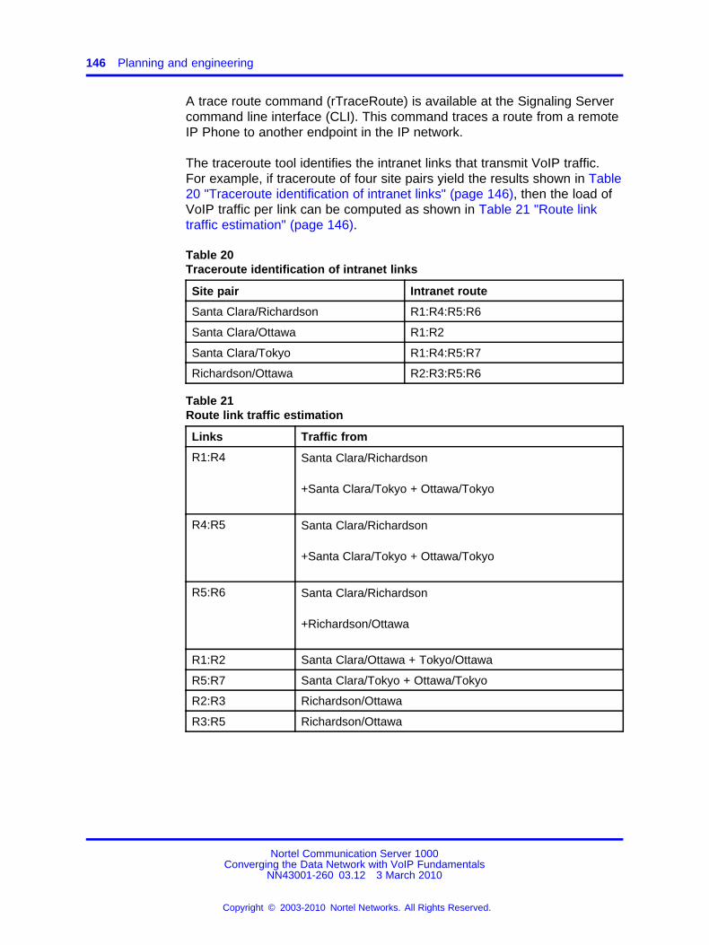
146 Planning and engineering
A trace route command (rTraceRoute) is available at the Signaling Servercommand line interface (CLI). This command traces a route from a remoteIP Phone to another endpoint in the IP network.
The traceroute tool identifies the intranet links that transmit VoIP traffic.For example, if traceroute of four site pairs yield the results shown in Table20 "Traceroute identification of intranet links" (page 146), then the load ofVoIP traffic per link can be computed as shown in Table 21 "Route linktraffic estimation" (page 146).
Table 20Traceroute identification of intranet links
Site pair Intranet route
Santa Clara/Richardson R1:R4:R5:R6
Santa Clara/Ottawa R1:R2
Santa Clara/Tokyo R1:R4:R5:R7
Richardson/Ottawa R2:R3:R5:R6
Table 21Route link traffic estimation
Links Traffic from
R1:R4 Santa Clara/Richardson
+Santa Clara/Tokyo + Ottawa/Tokyo
R4:R5 Santa Clara/Richardson
+Santa Clara/Tokyo + Ottawa/Tokyo
R5:R6 Santa Clara/Richardson
+Richardson/Ottawa
R1:R2 Santa Clara/Ottawa + Tokyo/Ottawa
R5:R7 Santa Clara/Tokyo + Ottawa/Tokyo
R2:R3 Richardson/Ottawa
R3:R5 Richardson/Ottawa
Nortel Communication Server 1000Converging the Data Network with VoIP Fundamentals
NN43001-260 03.12 3 March 2010
Copyright © 2003-2010 Nortel Networks. All Rights Reserved.
.
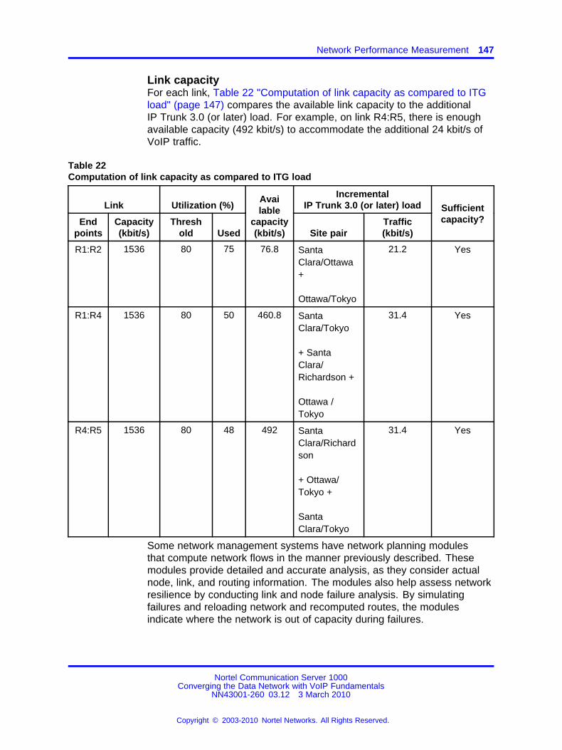
Network Performance Measurement 147
Link capacityFor each link, Table 22 "Computation of link capacity as compared to ITGload" (page 147) compares the available link capacity to the additionalIP Trunk 3.0 (or later) load. For example, on link R4:R5, there is enoughavailable capacity (492 kbit/s) to accommodate the additional 24 kbit/s ofVoIP traffic.
Table 22Computation of link capacity as compared to ITG load
Link Utilization (%)Incremental
IP Trunk 3.0 (or later) load
Endpoints
Capacity(kbit/s)
Threshold Used
Available
capacity(kbit/s) Site pair
Traffic(kbit/s)
Sufficientcapacity?
R1:R2 1536 80 75 76.8 SantaClara/Ottawa+
Ottawa/Tokyo
21.2 Yes
R1:R4 1536 80 50 460.8 SantaClara/Tokyo
+ SantaClara/Richardson +
Ottawa /Tokyo
31.4 Yes
R4:R5 1536 80 48 492 SantaClara/Richardson
+ Ottawa/Tokyo +
SantaClara/Tokyo
31.4 Yes
Some network management systems have network planning modulesthat compute network flows in the manner previously described. Thesemodules provide detailed and accurate analysis, as they consider actualnode, link, and routing information. The modules also help assess networkresilience by conducting link and node failure analysis. By simulatingfailures and reloading network and recomputed routes, the modulesindicate where the network is out of capacity during failures.
Nortel Communication Server 1000Converging the Data Network with VoIP Fundamentals
NN43001-260 03.12 3 March 2010
Copyright © 2003-2010 Nortel Networks. All Rights Reserved.
.

148 Planning and engineering
Insufficient link capacityIf there is not enough link capacity, implement one or more of the followingoptions:
• Use the G.723 codec series. Compared to the default G.729AB codecwith 30 ms payload, the G.723 codecs use 9% to 14% less bandwidth.
• Upgrade the bandwidth.
Other intranet resource considerationsBottlenecks caused by nonWAN resources are not frequent. For acomplete assessment, consider the impact of incremental VoIP traffic onrouters and LAN resources in the intranet. Perhaps the VoIP traffic istraversing LAN segments that are saturated, or traversing routers whoseCPU utilization is high.
DelayDelay is defined as the amount of time required for application datato reach its intended destination. Delay causes significant Quality ofExperience (QoE) issues with voice and video applications. Otherapplications, such as Fax transmissions, with excessive delay causes theapplication to time out and fail.
Some applications can compensate for specified amounts of delay, butafter that amount is exceeded, QoS is compromised. VoIP and gatewaysalso provide delay compensation by using local buffering.
Delay can be fixed or variable. Variable delay is also known as jitter.
Some contributions to fixed (baseline) delay are as follows:
• Application:based delay, such as:
— voice codec processing
— jitter buffer delay
• Serialization delay — Delay of the voice packet at each hop of thephysical network, which depends on link speed (a fixed, constant valuefor each link).
• Propagation delay — Delay caused by the finite speed at whichelectronic signals can travel through a transmission medium.
In VoIP, end:to:end delay on a call is the total time elapsed from speakinginto an transmitter at one end to hearing the reconstructed sound on areceiver at the other end. Delay has a significant impact on the quality ofa voice call. Most listeners can detect delay greater than 100 ms. Delaybecomes annoying at the following levels:
Nortel Communication Server 1000Converging the Data Network with VoIP Fundamentals
NN43001-260 03.12 3 March 2010
Copyright © 2003-2010 Nortel Networks. All Rights Reserved.
.

Network Performance Measurement 149
• for G.711 codec, 250 ms
• for G.729AB codec, 150 ms
Figure 34 "Sources of packet delay" (page 149) shows the sources ofpacket delay.
Figure 34Sources of packet delay
Table 23 "Delay characteristics of voice traffic" (page 149) lists the networkelements where delay occurs, and the type of that delay.
Table 23Delay characteristics of voice traffic
Packet action Network element Delay type
Voice codec algorithmic processing fixed delayEntrance (ingress) node audioprocessing Voice payload packetization fixed delay
Entrance (ingress) node packetqueueing
Packet contention for network port variable delay
LAN and WAN link speeds fixed delay (pernetwork segment type)
Propagation over the network fixed delay (pertransmission distance)
Data network transmission
Packet contention at network nodes variable delay
Packet contention for network port variable delayExit (egress) node packetqueueing Packet jitter buffer fixed delay
Exit (egress) node audioprocessing
Voice decoder processing fixed delay
Nortel Communication Server 1000Converging the Data Network with VoIP Fundamentals
NN43001-260 03.12 3 March 2010
Copyright © 2003-2010 Nortel Networks. All Rights Reserved.
.

150 Planning and engineering
ATTENTIONThe previous table does not account for enhanced applications, such as packetencryption, tunnelling, and Virtual Private Networks (VPN), which add delay dueto the buffering of the extra payload, additional Digital Signal Processing (DSP),and repacketization. These contribute to extra delay and should be included ina delay analysis.
Effects of delay on voice qualityThe overall delay budget for a voice call from the time one party speaks, tothe time the voice is heard by the listener, should not exceed 150 ms forgood quality voice over land line connections; although 250 ms is oftentolerated for G.711 calls, if there is no packet loss the amount of delayis often longer, but unavoidable, for satellite and other types of wirelessconnections.
Studies show that as the 150:ms delay budget is exceeded, users perceivethe delay as poor voice quality, especially for the compressed codecs.Every time a VoIP packet passes through a device or network connection,delay is introduced. A significant amount of delay is introduced overlow:bandwidth connections.
Components of delayEnd:to:end delay is caused by many components, such as:
• Propagation delay
• Serialization delay
• queueing delay
• Routing and hop count
• IP Trunk 3.0 (or later) system delay
Propagation delay Propagation delay is affected by the mileage andmedium of links traversed. Within an average:size country, one:waypropagation delay over terrestrial lines is under 18 ms; within the U.S.,the propagation delay from coast:to:coast is under 40 ms. To estimatethe propagation delay of long:haul and transoceanic circuits, use therule:of:thumb of 1 ms per 100 terrestrial miles.
If a circuit goes through a satellite system, estimate each hop betweenearth stations to contribute 260 ms to the propagation delay.
Serialization delay Serialization delay is the time it takes to transmit thevoice packet one bit at a time over a WAN link. The serialization delaydepends on the voice packet size and the link bandwidth, and is calculatedusing the following formula:
Nortel Communication Server 1000Converging the Data Network with VoIP Fundamentals
NN43001-260 03.12 3 March 2010
Copyright © 2003-2010 Nortel Networks. All Rights Reserved.
.

Network Performance Measurement 151
8 * (IP packet size in bytes) / (link bandwidth in kbit/s)
Table 24 "Serialization delay characteristics (in ms) for different packetsizes and link speeds" (page 151) shows the serialization delay (in ms) fordifferent packet sizes and link speeds.
Table 24Serialization delay characteristics (in ms) for different packet sizes and link speeds
Packet sizeLinkspeed
inKbit/s
40bytes
80bytes
88bytes
136bytes
184bytes
232bytes
280bytes
520bytes
1KB
1.48KB
56 5.7 11.4 12.5 19.4 26. 33.1 40.0 74.2 146.2 211.4
64 5.0 10.0 11.0 17.0 23.0 29.0 35.0 65.0 128.0 185.0
128 2.5 5.0 5.5 8.5 11.5 14.5 17.5 32.5 64.0 92.5
256 1.2 2.5 2.7 4.2 5.7 7.2 8.7 16.2 32.0 46.2
384 0.8 1.6 1.8 2.8 3.8 4.8 5.8 10.8 21.3 30.8
1000 0.3 0.6 0.7 1.0 1.4 1.8 2.2 4.1 8.1 11.8
1540 0.2 0.4 0.4 0.7 0.9 1.2 1.4 2.7 5.3 7.6
2048 0.1 0.3 0.5 0.71 0.9 1.09 2.0 4.0 4.0 5.7
10000 0.03 0.06 0.07 0.1 0.1 0.18 0.2 0.4 0.8 1.1
100000 0.003 0.006 0.007 0.01 0.015 0.019 0.022 0.04 0.08 0.1
150000 0.002 0.004 0.005 0.007 0.01 0.012 0.013 0.028 0.05 0.079
Table 25 "Serialization delay" (page 151) shows the serialization delay forvoice packets on a 64 kbit/s and 128 kbit/s link. The serialization delay onhigher speed links are considered negligible.
Table 25Serialization delay
CodecFrame
duration
Serializationdelay over
64 kbit/s link(ms)
Serializationdelay over
128 kbit/s link(ms)
10 ms 14.00 0.88
20 ms 24.00 1.50
G.711A/G.711U
30 ms 34.00 2.13
10 ms 5.25 0.33
20 ms 6.50 0.41
G.729A/G.729AB
30 ms 7.75 0.48
Nortel Communication Server 1000Converging the Data Network with VoIP Fundamentals
NN43001-260 03.12 3 March 2010
Copyright © 2003-2010 Nortel Networks. All Rights Reserved.
.

152 Planning and engineering
Table 25Serialization delay (cont’d.)
CodecFrame
duration
Serializationdelay over
64 kbit/s link(ms)
Serializationdelay over
128 kbit/s link(ms)
G.723.15.3 kbit/s
30 ms 6.50 0.41
G.723.16.3 kbit/s
30 ms 7.00 0.44
Queueing delay Queueing delay is the time it takes for a packet to waitin transmission queue of the link before it is serialized. On a link wherepackets are processed in first:come:first:serve order, the average queueingtime in ms is estimated using the following formula:
p*p*(average intranet packet in bytes) / (1:p) / (link speed in kbit/s)
where p is the link utilization level.
The average size of intranet packets carried over WAN links is between250 and 500 bytes. The following figure shows the average queueingdelay of the network based on a 300:byte average packet size.
Figure 35Queueing delay of various links
Nortel Communication Server 1000Converging the Data Network with VoIP Fundamentals
NN43001-260 03.12 3 March 2010
Copyright © 2003-2010 Nortel Networks. All Rights Reserved.
.

Network Performance Measurement 153
The previous figure shows queueing delays can be significant for links withbandwidth under 512 kbit/s. Higher speed links can tolerate much higherutilization levels.
Routing and hop count Each site pair takes different routes overthe intranet. The route taken determines the number and type ofdelay components that add to end:to:end delay. Sound routing in thenetwork depends on correct network design at many levels, such as thearchitecture, topology, routing configuration, link, and speed.
VoIP system delay Together, the transmitting and receiving IP Trunk3.0 (or later) nodes contribute a processing delay of about 33 ms to theend:to:end delay. This is the amount of time required for the encoderto analyze and packetize speech, and is required by the decoder toreconstruct and depacketize the voice packets.
There is a second component of delay that occurs on the receiving IPTrunk 3.0 (or later) node. For every call that terminates on the receiver,there is a jitter buffer which serves as a holding queue for voice packetsarriving at the destination ITG. The purpose of the jitter buffer is to smoothout the effects of delay variation, so that a steady stream of voice packetscan be reproduced at the destination. The default jitter buffer delay forvoice is 60 ms.
Other delay components Other delay components, considered minor,are as follows:
• Router (transit) processing delay
The time it takes to forward a packet from one link to another onthe router. In a healthy network, router processing delay is a fewmilliseconds.
• LAN segment delay
The transmission and processing delay of packets through a healthyLAN subnet takes one or two milliseconds.
Measuring end:to:end network delayEnd:to:end delay and error characteristics of the intranet must bemeasured so the technician can set realistic voice quality expectations forintranet voice services.
The basic tool used in IP networks to measure end:to:end network delay isthe ping program. Ping takes a delay sample by sending an ICMP packetfrom the host of the ping program to a destination server, and waits for thepacket to make a round trip.
Nortel Communication Server 1000Converging the Data Network with VoIP Fundamentals
NN43001-260 03.12 3 March 2010
Copyright © 2003-2010 Nortel Networks. All Rights Reserved.
.

154 Planning and engineering
Some implementations of ping support the :v option for setting the TOS.CS 1000 allows the 8:bit DiffServ/TOS field to be set to any value specifiedby the IP network administrator for QoS management purposes. Forexample, a decimal value of 36 entered in TM is interpreted as TOSPrecedence = Priority and Reliability = High. If the :v option is not used,and if ping measurements are made on an intranet that uses prioritizationbased on the TOS field, the round trip time (rtt) measured is higher thanthe actual delay of voice packets. See “Queueing” (page 136).
ATTENTIONEnsure that the DiffServ bytes are configured to their intended operationalvalues before taking measurements.
CS 1000 also has a utility called remote ping (rPing) so an IP Phone canping an IP address. The rPing command can be run from the SignalingServer OAM command line interface (CLI). See “Network DiagnosticUtilities” (page 232).
To ensure the delay sample results are representative of theIPLine_Node1:
1. Attach the ping host to a healthy LAN segment.
2. Attach the LAN segment to the router intended to support the IPTelephony node.
3. Choose a destination host by following the same critical guidelines asfor the source host.
The size of the ping packets can be any number; the default is 60 bytes.
Sample ping output:
IPLine_Node1% ping :s subnetA 60PING subnetA (10.3.2.7): 60 data bytes68 bytes from (10.3.2.7): icmp_seq=0 ttl=225 time=97ms68 bytes from (10.3.2.7): icmp_seq=0 ttl=225 time=100ms68 bytes from (10.3.2.7): icmp_seq=0 ttl=225 time=102ms68 bytes from (10.3.2.7): icmp_seq=0 ttl=225 time=97ms68 bytes from (10.3.2.7): icmp_seq=0 ttl=225 time=95ms68 bytes from (10.3.2.7): icmp_seq=0 ttl=225 time=94ms68 bytes from (10.3.2.7): icmp_seq=0 ttl=225 time=112ms68 bytes from (10.3.2.7): icmp_seq=0 ttl=225 time=97ms^? ::: IPLine_Node1 ping Statistics :::8 packets transmitted, 8 packets received, 0% packet lossround:trip (ms) min/avg/max = 94/96/112
Ping results can vary.
Nortel Communication Server 1000Converging the Data Network with VoIP Fundamentals
NN43001-260 03.12 3 March 2010
Copyright © 2003-2010 Nortel Networks. All Rights Reserved.
.
Network Performance Measurement 155
ATTENTIONThe round:trip time (rtt) is indicated by the time field.
Assessment of sample ping output The rtt from the PING output variesas you can only obtain a delay characteristic of the intranet from repeatedrtt sampling. To obtain a delay distribution, the ping tool can be embeddedin a script that controls the frequency of the ping probes and timestampsand stores the samples in a raw data file. The file can then be analyzedlater using a spreadsheet or another application. The technician canalso check if the intranet network management software includes delaymeasurement modules that can obtain a delay distribution for a specificroute.
Delay characteristics vary depending on the site pair and the time:of:day.The site pair is defined as the measurement between the host IP Lineand the remote subnet (for example, IP Line to subnet A in Figure 28"Large campus network example" (page 116)). The assessment of theintranet must include taking delay measurements for each IP Line sitepair. If there is a significant variation of traffic on the intranet, include pingsamples during the intranet peak hour. For a complete assessment ofdelay characteristics of the intranet, obtain ping measurements over aperiod of at least one week.
Adjusting ping statisticsPing statistics measure the intranet prior to CS 1000 installation, themeasurement does not take into consideration the expected load createdby CS 1000users.
One:way and round:trip Ping statistics are based on round:tripmeasurements, while QoS metrics in the Transmission Rating model areone:way. Halve the delay and packet error ping statistics to ensure thecomparison is valid.
Adjustment due to IP Line processing Ping statistics are measuredfrom ping host to ping host. Transmission Rating QoS metrics are fromend user to end user, and include components outside the intranet. Theping statistic for delay needs to be further modified by adding 93ms toaccount for the processing and jitter buffer delay of the nodes.
There is no need to adjust error rates.
If the intranet measurement barely meets the round:trip QoS objectives,the technician must be aware of the possibility that one:way QoS is notbeing met in one of the directions of flow. This can apply even if the flowis on a symmetric route due to asymmetric behavior of data processingservices.
Nortel Communication Server 1000Converging the Data Network with VoIP Fundamentals
NN43001-260 03.12 3 March 2010
Copyright © 2003-2010 Nortel Networks. All Rights Reserved.
.

156 Planning and engineering
Other measurement considerationsIf the intranet capacity is tight and the VoIP traffic significant, considermaking intranet measurements under load. Load can be appliedusing traffic generator tools. The amount of load should match the IPTrunk:offered traffic estimated in “Prerequisites” (page 141) .
Reducing delaysLink delay is the time it takes for a voice packet to be queued on thetransmission buffer of a link until it is received at the next hop router. Linkdelay can be reduced by:
• Upgrading link capacity — to reduce the serialization delay of thepacket, and also reduce link utilization and queueing delay. Before youupgrade a link, the technician must check both routers connected tothe link and ensure compliance with router configuration guidelines.
• Implementing QoS mechanisms
To determine the links to upgrade, list all intranet links that support the IPLine traffic. This can be derived from the traceroute output for each sitepair. Use the intranet link utilization report and note the links used mostoften and the slowest links. Estimate the link delay of suspect links usingthe traceroute results.
Example A 256 kbit/s link from router1 to router2 has a high utilization.The following traceroute output traverses this link:
IPLine_Node1% traceroute SubnetAtraceroute to SubnetA (10.3.2.7), 30 hops max, 32 bytepackets
router1 (10.8.0.1) 1 ms 1 ms 1 msrouter2 (10.18.0.2) 42 ms 44 ms 38 msrouter3 (10.28.0.3) 78 ms 70 ms 81 msrouter4 (10.3.0.1) 92 ms 90 ms 101 msSubnetA (10.3.2.7) 94 ms 97 ms 95 ms
The average rtt time on the example link is 40 ms. The one:way link delayis 20 ms, of which the circuit transmission and serialization delay are just afew milliseconds. Most of the link delay is due to queueing.
Reducing hop countConsider the current network topology and whether a more efficient designwhich reduces hop count can be implemented. Reducing hops reducesfixed and variable IP packet delay, improves VoIP QoS and can alsosimplify end:to:end QoS engineering for packet delay, jitter, and packetloss.
Nortel Communication Server 1000Converging the Data Network with VoIP Fundamentals
NN43001-260 03.12 3 March 2010
Copyright © 2003-2010 Nortel Networks. All Rights Reserved.
.

Network Performance Measurement 157
Recording routesThe traceroute tool records routing information for all source:destinationpairs as part of the network assessment. An example of traceroute outputis shown below:
ipline_node1% traceroute subnetAtraceroute to subnetA 10.3.2.7, 30 hops max, 32 byte packets1 r6 (10.8.0.1) 1 ms 1 ms 1 ms2 r5 (10.18.0.2) 42 ms 44 ms 38 ms3 r4 (10.28.0.3) 78 ms 70 ms 81 ms4 r1 (10.3.0.1) 92 ms 90 ms 101 ms5 subnetA (10.3.2.7) 94 ms 97 ms 95 ms
Traceroute is also used to verify whether routing in the intranet issymmetric for each source:destination pair. This is done using the :gloose source routing option, for example:
ipline_node1% traceroute :g subnetA ipline_node1
For information about the rTraceRoute command, see “Network DiagnosticUtilities” (page 232).
Routing issuesUnnecessary delay can be introduced by routing irregularities. A routingimplementation can overlook a substantially better route. A high:delayvariation can be caused by routing instability, incorrectly configuredrouting, inappropriate load splitting, or frequent changes to the intranet.Severe asymmetrical routing results in one site perceiving a poorer QoSthan another.
The traceroute program can be used to uncover routing anomalies. Thenrouting implementation and policies can be audited and corrected.
JitterJitter (also known as variable delay) is the variation in the amount of time ittakes for consecutive packets to travel from sender to receiver. There is afixed baseline delay (the absolute fastest time for a voice packet to passthrough the network), and a variation in packet flow. The variation in thedelay is jitter.
The primary cause of jitter (variable delay) is contention (competitionfor network access), also known as queueing delay. Variable delays areaffected by the amount of network traffic.
Jitter has a pronounced effect on real:time, delay:sensitive applications,such as video and voice. These applications need to receive packets ata constant rate, with a fixed delay between consecutive packets. If the
Nortel Communication Server 1000Converging the Data Network with VoIP Fundamentals
NN43001-260 03.12 3 March 2010
Copyright © 2003-2010 Nortel Networks. All Rights Reserved.
.

158 Planning and engineering
arrival rate varies, jitter occurs and application performance degrades.Minimal jitter might be acceptable, but if jitter increases, the applicationcould become unusable.
Some settings on devices such as VoIP gateways and IP Phones cancompensate for a finite (specified) amount of jitter.
If an adaptive jitter buffer is used, delay is kept to a minimum duringperiods of low jitter. The adaptive buffer can adjust to high levels of jitter,within a limited range, during periods of high traffic volume. If the networkbecomes congested, jitter and packet loss can become undefined, andreal:time interactive applications can become unusable.
Voice applications require the voice packets to be fed to the decoderat a constant rate. If the next voice packet does not arrive in time totake its turn to be decoded, the packet is considered lost. Packet LossConcealment (PLC) attempts to smooth over the lost voice packet. PLCreplays the previous voice packet until the next voice packet arrives. APLC algorithm can repair losses of 40:60 ms. Longer gaps in the signalmust be muted. If jitter is high, whole groups of packets can be late or lost,and output can contain muted segments.
All networks have some jitter, due to differences in delay at each networknode, as packets are queued. If jitter is contained within specified limits,QoS can be maintained.
In VoIP, jitter is the total amount of variable delay encountered during theend:to:end processing of voice packets.
Jitter buffers are used on the receive:side of a call to smooth out smallvariations in the packet time of arrival. This allows data to be unpackedand sent to the decoder as a constant stream. As all buffering increasesend:to:end delay, jitter buffer length (duration) must be kept to a minimum.If a network has been engineered to have minimal jitter, the jitter buffercan be very small.
The following factors contribute to the total variation in delay:
• packet contention during node queueing
• network conditions, such as routing and transmission queueing
• router and switch (statistical multiplexer) performance under load
• link speed
• voice and data packet size
• exit (egress) queue buffer size
Nortel Communication Server 1000Converging the Data Network with VoIP Fundamentals
NN43001-260 03.12 3 March 2010
Copyright © 2003-2010 Nortel Networks. All Rights Reserved.
.

Network Performance Measurement 159
Queueing delay occurs at the exit port of every device on the network.
Call Admission Control (CAC) performs packet admission and blockingfunctions. Voice packets are admitted to the network when the networkcan adequately support them. The packets are denied admission when thenetwork cannot support them as defined in the Service Level Agreement.
When voice and data packets share a low:speed WAN connection (< 1Mbit/s), the larger data packets introduce queueing delay to the smallervoice packets waiting to queue onto the WAN connection. Therefore, thesmaller voice packets do not arrive at the same fixed time interval as theyare transmitted from their source. The arrival time of the voice packetsvaries because interjected data packets of varying sizes introduce avarying amount of jitter (queueing delay).
Jitter buffersWhen voice and data packets share a high:speed connection (> 1 Mbit/s),the jitter introduced by the WAN connection becomes insignificant. Thejitter in high:speed networks is affected by the buffer size of a router andthe load/congestion in the router. Jitter buffers are designed to smooth outirregular packet arrival by collecting incoming packets and holding them ina buffer long enough to allow the slowest packets to arrive. The packetsare then played in the correct sequence. Jitter buffers solve the late andlost packet problem, but add to total end:to:end delay.
Late packetsPackets that arrive outside the window allowed by the jitter buffer arediscarded by IP Line. To determine which ping samples to ignore,calculate the average one:way delay based on all the samples.
To calculate late packets, double the value of the nominal jitter buffersetting. For example, assume:
• the average one:way delay is 50 ms
• the jitter buffer is set to a nominal (or average) value of 40 ms
• the maximum value is 2 x 40 + 50 = 130 ms
Therefore, any packet with a one:way delay of greater than 130 ms is late,and must be added to the total number of packets lost.
Adjusting jitter buffer sizeThe jitter buffer parameters directly affect end:to:end delay. Lowering thevoice playout settings decreases one:way delay, but there is less waitingtime for voice packets that arrive late.
Nortel Communication Server 1000Converging the Data Network with VoIP Fundamentals
NN43001-260 03.12 3 March 2010
Copyright © 2003-2010 Nortel Networks. All Rights Reserved.
.

160 Planning and engineering
The jitter buffer setting is configured on the voice gateway channels ofthe Voice Gateway Media Card, and are sent out to IP Phones. The jitterbuffer size is set when you configure the DSP Profiles:
• in the IP Telephony application
• in the selected codec in Element Manager
The jitter buffer is statically configured and is the same for all devices inthe network. The jitter buffer size range is 0:200 ms. The default jitterbuffer value is 50 ms. However, the jitter buffer setting that is used on theVoice Gateway Media Card is a multiple of the codec frame size. Thesetting is automatically adjusted to be greater than or equal to the jitterbuffer value set in the DSP Profile tab. As each call is set up, the jitterbuffer for each device is set to the nearest whole number increment of theselected codec frame size.
For example, if the jitter buffer is configured as the default 50 ms in theDSP Profiles, but a 20 ms codec is used, the jitter buffer is set to 60 ms,which is the nearest whole number increment.
50 ms / 20 ms = 2.52.5 rounded up to the nearest whole number increment is 33 x 20 ms = 60 ms
If the jitter buffer is configured as zero, the depth of the jitter buffer is setto the smallest value the device can support. In practice, the optimumdepth of the jitter queue is different for each call. For telephones on a localLAN connection, a short jitter queue is desirable to minimize delay. Fortelephones several router hops away, a longer jitter queue is required.
Lowering the jitter buffer size decreases the one:way delay of voicepackets. If the setting for the jitter buffer size is too small, packets arediscarded unnecessarily. Discarded packets result in poor speech qualityand can be heard as clicks or choppy speech.
If the technician decides to discard packets to downsize the jitter buffer,the technician must do the following:
• Check the delay variation statistics.
Obtain the one:way delay distributions that originate from all sourceIP Line sites.
• Compute the standard deviation of one:way delay for every flow.
Some traffic sources with few hop counts yield small delay variations,but it is the flows that produce great delay variations that should beused to determine whether it is acceptable to resize the jitter buffer.
• Compute the standard deviation (s) of one:way delay for that flow.
Nortel Communication Server 1000Converging the Data Network with VoIP Fundamentals
NN43001-260 03.12 3 March 2010
Copyright © 2003-2010 Nortel Networks. All Rights Reserved.
.
Network Performance Measurement 161
Do not set the set the jitter buffer size smaller than 2 seconds.
The IP Phone firmware must also be configured for jitter buffers. However,instead of specifying the jitter buffer size in ms, it is configured with thenumber of frames to be held in the jitter buffer, such as 1, 2, or 3.
ATTENTIONTo achieve maximum voice quality, Nortel strongly recommends that IP Phonefirmware be configured with a jitter buffer size of 3; however, a well:engineerednetwork can function with a jitter buffer size of 2, which increases perceivedvoice quality.
Jitter measurement toolsAfter a CS 1000 system has been installed, the average jitter experiencedby IP Phones or media cards may be monitored on a per:call basis byusing the RTPTraceShow command from the signaling server CLI. The CS1000system can also be configured to transmit SNMP alarms an averagejitter level is exceeded.
Packet lossPacket loss is the number of packets lost during transmission. It is usuallymeasured as a percentage of the total packets exchanged.
Physical medium lossLoss can occur due to errors created by the physical medium used totransmit the data.
Most land line connections have very low loss, measured in Bit Error Rate(BER). Wireless connections, such as satellite, mobile, or fixed wirelessnetworks have a high BER. The BER can vary due to the following:
• radio frequency interference
• cell hand:off during roaming calls
• weather conditions, such as fog and rain
• physical obstacles, such as trees, buildings, and mountains
Wireless technology usually transmits redundant information, as packetsare often dropped during transmission due to the physical medium.
Congestion lossCongestion loss consists of true loss (buffer overflow at router queues)and late packets. Loss also occurs when congested network nodes droppackets. The majority of packet loss is caused by congestion.
Nortel Communication Server 1000Converging the Data Network with VoIP Fundamentals
NN43001-260 03.12 3 March 2010
Copyright © 2003-2010 Nortel Networks. All Rights Reserved.
.

162 Planning and engineering
VoIP uses User Datagram Protocol (UDP). UDP is a connectionlessprotocol which, unlike TCP, cannot retransmit lost packets. A packet issent from the source to the destination with no means to determine if thatpacket was received or not.
If a network becomes congested to the point that packets are lost, voicequality is degraded. Traffic is discarded if the transmit queue of an uplinkhas less available bandwidth than the total amount of bandwidth trying touse that link. This situation is also known as a bottleneck.
Congestion can lead to packet loss. Mechanisms to avoid networkcongestion can be used. One such mechanism is called Random EarlyDiscard (RED), which deliberately drops packets after the network trafficreaches a specified threshold. The dropped packets cause TCP to reduceits window size and send fewer packets, thus reducing network traffic.RED provides congestion control only for applications or protocols thathave the TCP:like ability to reduce network traffic.
UDP packets dropped in a network cannot be retransmitted. Flow ratesare not adjusted by devices that communicate through UDP.
Without discard priorities, you must separate packets into different queuesin a network node to provide different levels of service. This is expensiveto implement, as only a limited number of hardware queues (usually eightor fewer) are available on networking devices. Though some deviceshave software:based queues, their increased use reduces network nodeperformance.
With discard priorities, although packets are placed in the same queue,they are divided into virtual subqueues, determined by their assigneddiscard priority. For example, if a product supports three discard priorities,the product queue provides three subqueues and; therefore, three QoSlevels.
Packets are usually lost due to a router dropping packets when links arecongested.
Individual packets that are delayed much more than the baseline delay(variable delay) are referred to as jitter. Excess jitter causes packet lossthat can result in choppy or unintelligible speech.
Packet loss occurs
• during network congestion
• as a result of misconfigured LAN settings
Nortel Communication Server 1000Converging the Data Network with VoIP Fundamentals
NN43001-260 03.12 3 March 2010
Copyright © 2003-2010 Nortel Networks. All Rights Reserved.
.

Network Performance Measurement 163
• as a result of misconfigured clock settings
• if bit errors in the network
ATTENTIONTo achieve maximum voice quality, Nortel strongly recommends that packet loss= 0%.
Packet Loss Concealment (PLC) is used to minimize the noticeable effectsof packet loss.
Measuring end:to:end packet lossAfter a CS 1000 installation, check RTPTraceShow and PVQM SNMPalarms.
The ping program also reports whether the ICMP packet successfullycompleted its round trip. Use the same ping host setup to measureend:to:end error, and in making delay measurements, use the samepacket size parameter.
Multiple ping samples must be used when sampling for error rate.Packet loss rate (PLR) is the error rate statistic collected by multiple pingsamples. To be statistically significant, at least 300 samples must be used.Obtaining an error distribution requires that you run ping over a long periodof time.
Packet Loss ConcealmentThe term codec stands for coder/decoder. A codec executes acompression algorithm (a specialized computer program) that reduces thenumber of bytes required to encode digital data. This reduces packet sizeand bandwidth requirements. As well, smaller packets are less likely tobe lost.
Codecs designed for packet networks, such as G.729, have built:in PacketLoss Concealment (PLC). PLC minimizes the impact of lost packets onan audio signal, by mixing in synthesized speech derived from previouspackets.
When a speech codec operates in normal mode, a receiver decodespackets and sends the output to an audio port. A PLC algorithm saves acopy of the recent audio output, which is used to create a signal to replacethe missing speech if lost data is encountered. How this information isused depends on the PLC algorithm. Some simple algorithms smoothover gaps in the signal to remove clicks. Other algorithms replay anearlier packet to fill in the gap. More sophisticated algorithms tweak thereplacement signal to make it sound natural. The best algorithms can
Nortel Communication Server 1000Converging the Data Network with VoIP Fundamentals
NN43001-260 03.12 3 March 2010
Copyright © 2003-2010 Nortel Networks. All Rights Reserved.
.

164 Planning and engineering
repair a 20 to 40 ms gap with little audible distortion. The PLC operatesconstantly, generating speech to replace the next packet in the event it islost. The use of a PLC adds a small fixed delay to the call baseline delay.
PLC is necessary to achieve acceptable IP speech quality.
Reducing packet lossPacket loss in intranets is generally related to congestion in the network.Bottlenecks in links occur with high packet loss due to packets droppedbecause they arrive faster than the link can transmit them. The task ofupgrading highly utilized links can remove the source of packet loss on aparticular flow. An effort to reduce hop count gives fewer opportunities forrouters and links to drop packets.
Other causes of packet loss, not related to queueing delay, are as follows:
• Poor link quality — the underlying circuit could have transmissionproblems, high line error rates, and be subject to frequent outages.The circuit might possibly be provisioned on top of other services,such as X.25, Frame Relay, or ATM. Check with the service providerfor information.
• Overloaded CPU — this is a commonly:monitored statistic collected bynetwork management systems. If a router is overloaded, it constantlyperforms processing:intensive tasks, which impede the router fromforwarding packets. Determine the CPU utilization threshold andcheck if a suspect router conforms to it. The router may need to bereconfigured or upgraded.
• Saturation — routers can be overworked when configured with toomany high capacity and high traffic links. Ensure that routers aredimensioned according to vendor guidelines.
• LAN saturation — packets may be dropped on under engineered orfaulty LAN segments.
• Jitter buffer too small — packets that arrive at the destination, but toolate to be placed in the jitter buffer, should be considered lost packets.
• Frame slips — ensure that clocks are synchronized correctly.
Network delay and packet loss evaluation exampleFrom ping data, calculate the average one:way delay (halved from pingoutput and adding 93 ms IP Trunk 3.0 (or later) processing delay) andstandard deviation for latency. Perform a similar calculation for packet losswithout adjustment.
Nortel Communication Server 1000Converging the Data Network with VoIP Fundamentals
NN43001-260 03.12 3 March 2010
Copyright © 2003-2010 Nortel Networks. All Rights Reserved.
.

Network Performance Measurement 165
Add a standard deviation to the mean of both delay and loss for planningpurposes. A customer might want to know whether traffic fluctuation intheir intranet reduces the user QoS.
Table 26 "Sample measurement results for G.729A codec" (page165) provides a sample measurement of network delay and packet loss forthe G.729A codec between various nodes.
Table 26Sample measurement results for G.729A codec
Destinationpair
Measured one:waydelay (ms)
Measuredpacket loss (%)
Expected QoS level(See Table 31 "QoSlevels" (page 168) )
Mean Mean+s Mean Mean+s Mean Mean+s
SantaClara/Richardson
171 179 1.5 2.1 Excellent Good
SantaClara/Ottawa
120 132 1.3 1.6 Excellent Excellent
SantaClara/ Tokyo
190 210 2.1 2.3 Good Good
Richardson/Ottawa
220 235 2.4 2.7 Good Good
As an example, the delay and loss pair of traffic from Santa Clara toRichardson (171 ms and 1.5%) will meet the excellent criterion, but theircounterpart with standard deviation (179 ms and 2.1%) can achieve onlygood QoS.
In contrast, the site pair Santa Clara/Ottawa has both QoS levels ofmean and mean+s falling in the excellent region. The customer has moreconfidence that during peak traffic period, the excellent service level islikely to be upheld (better than 84% chance under the assumption ofNormal distribution).
Estimate voice qualityThe perceived quality of a telephone call depends on many factors, suchas codec characteristics, end:to:end delay, packet loss, and the perceptionof the individual listener.
The E:Model Transmission Planning Tool produces a quantifiable measureof voice quality based on relevant factors. For more information aboutthe E:Model and its application, see the ITU:T recommendations E.107and E.108.
Nortel Communication Server 1000Converging the Data Network with VoIP Fundamentals
NN43001-260 03.12 3 March 2010
Copyright © 2003-2010 Nortel Networks. All Rights Reserved.
.

166 Planning and engineering
A simplified version of the E:Model is applied to provide an estimate ofthe voice quality that the user can expect, based on various configurationchoices and network performance metrics.
The simplified E:Model is as follows:
R = 94 – lc – ld – lp
where
lc = (see Table 27 "Impairment factors of codecs"(page 166))
ld = delay impairment (see Table 28 "Impairmentfactors due to network delay" (page 167))
lp = packet loss impairment (see Table 29 "Impairmentfactors due to packet loss" (page 167))
ATTENTIONThis model takes into account some characteristics of the IP Phone and;therefore, the impairment factors are not identical to those shown in the ITU:Tstandards.
See Table 30 "R value translation" (page 167) for the translation of Rvalues into user satisfaction levels.
Table 27Impairment factors of codecs
CodecCodec impairment (lc)
(ms frames)
G.711 0
G.711 a:law 8
G.711 mu:law 0
G.723.1 4
G.729AG.729AB
18
G.729A/AB 11 : 20 or 30
G.729A/AB 16 : 40 or 50
G.723.1 (5.3 kbit/s) 19
G.723.1 (6.3 kbit/s) 15
Nortel Communication Server 1000Converging the Data Network with VoIP Fundamentals
NN43001-260 03.12 3 March 2010
Copyright © 2003-2010 Nortel Networks. All Rights Reserved.
.
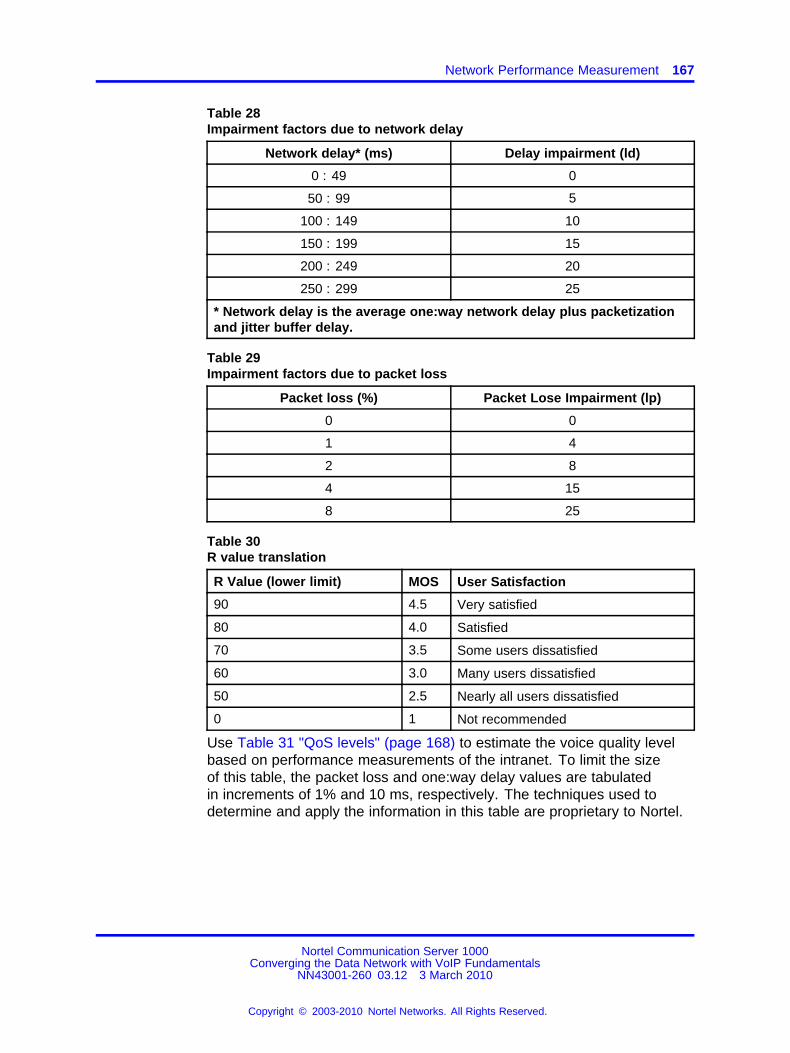
Network Performance Measurement 167
Table 28Impairment factors due to network delay
Network delay* (ms) Delay impairment (ld)
0 : 49 0
50 : 99 5
100 : 149 10
150 : 199 15
200 : 249 20
250 : 299 25
* Network delay is the average one:way network delay plus packetizationand jitter buffer delay.
Table 29Impairment factors due to packet loss
Packet loss (%) Packet Lose Impairment (lp)
0 0
1 4
2 8
4 15
8 25
Table 30R value translation
R Value (lower limit) MOS User Satisfaction
90 4.5 Very satisfied
80 4.0 Satisfied
70 3.5 Some users dissatisfied
60 3.0 Many users dissatisfied
50 2.5 Nearly all users dissatisfied
0 1 Not recommended
Use Table 31 "QoS levels" (page 168) to estimate the voice quality levelbased on performance measurements of the intranet. To limit the sizeof this table, the packet loss and one:way delay values are tabulatedin increments of 1% and 10 ms, respectively. The techniques used todetermine and apply the information in this table are proprietary to Nortel.
Nortel Communication Server 1000Converging the Data Network with VoIP Fundamentals
NN43001-260 03.12 3 March 2010
Copyright © 2003-2010 Nortel Networks. All Rights Reserved.
.

168 Planning and engineering
Table 31QoS levels
Voice quality levelNetworkdelay(ms)
Packet loss(%)
G.71120
G.729A/AB30
G.723.1 (6.3 kbit/s)30
0 – 49 0 excellent good fair
49 1 excellent fair fair
49 2 good fair fair
49 4 fair poor poor
49 8 poor not recommended not recommended
50 – 99 0 excellent fair fair
99 1 good fair fair
99 2 good fair poor
99 4 fair poor poor
99 8 poor not recommended not recommended
100 – 149 0 good fair fair
149 1 good fair poor
149 2 fair poor poor
149 4 fair poor not recommended
149 8 poor not recommended not recommended
150 – 199 0 fair poor poor
199 1 fair poor good
199 2 fair poor fair
199 4 poor not recommended not recommended
199 8 not recommended not recommended not recommended
200 – 249 0 poor not recommended not recommended
249 1 poor not recommended not recommended
249 2 poor not recommended not recommended
249 4 not recommended not recommended not recommended
249 8 not recommended not recommended not recommended
250 – 299 0 poor not recommended not recommended
299 1 poor not recommended not recommended
299 2 poor not recommended not recommended
Note: The QoS levels are equivalent to the following MOS values:excellent = 4.5, good = 4, fair = 3, poor = 2, and not recommended = less than 2.
Nortel Communication Server 1000Converging the Data Network with VoIP Fundamentals
NN43001-260 03.12 3 March 2010
Copyright © 2003-2010 Nortel Networks. All Rights Reserved.
.

Network Performance Measurement 169
Table 31QoS levels (cont’d.)
Voice quality levelNetworkdelay(ms)
Packet loss(%)
G.71120
G.729A/AB30
G.723.1 (6.3 kbit/s)30
299 4 not recommended not recommended not recommended
299 8 not recommended not recommended not recommended
Note: The QoS levels are equivalent to the following MOS values:excellent = 4.5, good = 4, fair = 3, poor = 2, and not recommended = less than 2.
Sample scenariosThe following examples provide sample scenarios.
Scenario 1 A local LAN has the following characteristics:
• G.711 codec
• 20 ms network delay
• 0.5% packet loss
To calculate R = 94 : lc : ld : lp, use Table 27 "Impairment factors ofcodecs" (page 166), Table 28 "Impairment factors due to network delay"(page 167), and Table 29 "Impairment factors due to packet loss" (page167):
• G.711 codec: lc = 0
• 20 ms network delay: ld = 0
• 0.5% packet loss: lp = 2
Then:
R = 94 : 0 : 0 : 2R = 92
Use the values in Table 31 "QoS levels" (page 168), a value of 92 meansthe users are very satisfied.
Scenario 2 A campus network has the following characteristics:
• G.711 codec
• 50 ms delay
• 1.0% packet loss
Nortel Communication Server 1000Converging the Data Network with VoIP Fundamentals
NN43001-260 03.12 3 March 2010
Copyright © 2003-2010 Nortel Networks. All Rights Reserved.
.

170 Planning and engineering
To calculate R = 94 : lc : ld : lp, use Table 27 "Impairment factors ofcodecs" (page 166), Table 28 "Impairment factors due to network delay"(page 167), and Table 29 "Impairment factors due to packet loss" (page167):
• G.711 codec: lc = 0
• 20 ms network delay: ld = 5
• 0.5% packet loss: lp = 4
Then:
R = 94 : 0 : 5 : 4R = 85
Use the values in Table 31 "QoS levels" (page 168), a value of 85 meansthat the users are satisfied.
Scenario 3 A WAN has the following characteristics:
• G.729 codec
• 30 ms network delay
• 2% packet loss
To calculate R = 94 : lc : ld : lp, use Table 27 "Impairment factors ofcodecs" (page 166), Table 28 "Impairment factors due to network delay"(page 167), and Table 29 "Impairment factors due to packet loss" (page167):
• G.711 codec: lc = 11
• 20 ms network delay: ld = 5
• 0.5% packet loss: lp = 8
Then:
R = 94 : 11 : 5 : 8R = 70
Use the values in Table 31 "QoS levels" (page 168), a value of 70 meanssome users are dissatisfied.
Expected voice quality evaluationAt the end of measurement and analysis, there should be a goodindication if the corporate intranet in its present state can deliver adequatevoice and fax services. Looking at the Expected QoS level column inTable 26 "Sample measurement results for G.729A codec" (page 165), theQoS level for each site pair can be gauged.
Nortel Communication Server 1000Converging the Data Network with VoIP Fundamentals
NN43001-260 03.12 3 March 2010
Copyright © 2003-2010 Nortel Networks. All Rights Reserved.
.
LAN design 171
In order to offer voice and fax services over the intranet, keep the networkwithin Good or Excellent QoS level at the Mean+s operating region. Faxservices should not be offered on routes that have only Fair or Poor QoSlevels.
If the expected QoS levels on some or all routes fall short of Good,evaluate the options and costs to upgrade the intranet. Estimate thereduction in one:way delay that must be achieved to raise the QoS level.You can raise Qos levels through a link upgrade, topology change, or animplementation of QoS in the network.
A decision can be made to keep costs down and accept a temporary FairQoS level for a selected route. In this case, having made a calculatedtrade:off in quality, carefully monitor the QoS level, reset expectations withthe end users, and be receptive to user feedback.
ATTENTIONNortel strongly recommends a minimum R:value of 70.
LAN designThis section describes the requirements to create and maintain a robust,redundant server network.
CS 1000 Release 6.0 configurationsA CS 1000 Release 6.0 system has 3 basic configurations designed tomeet varying network requirements:
• The “Normal” configuration suitable to larger installations which deploymultiple ELAN subnets or multiple CS 1000 systems within the sameUCM Security Domain.
• The “Small” configuration suitable for single system installations witha single ELAN subnet interconnecting all of the CS 1000 dependentelements.
• The “Managed Services” configuration which is suited to installationswhere complete isolation between the ELAN or “Signaling andManagement Network” and the various “Enterprise Networks” isrequired.
Normal configurationThe Normal configuration, shown in Figure 36 "Normal configuration"(page 172), is similar to existing CS 1000 installations where all TLANsubnets are routed to a single Enterprise Network. In CS1000 Release6.0, this configuration requires that the ELAN or Intra-System Signalingand Management Network be routed to/from the Enterprise Network. Afirewall is recommended between the networks to protect the intra-system
Nortel Communication Server 1000Converging the Data Network with VoIP Fundamentals
NN43001-260 03.12 3 March 2010
Copyright © 2003-2010 Nortel Networks. All Rights Reserved.
.

172 Planning and engineering
signaling on the ELAN. The TLAN subnets should be separate fromother subnets in the enterprise network and it is recommended that thesesubnets be isolated from the enterprise network using firewalls.
Figure 36Normal configuration
When installing a CS 1000 system in the Normal configuration, allmembers of the system are registered with the UCM security domain usingthe TLAN IP address (or FQDN) of the UCM Primary Security server. TheFQDN of each member is associated with the TLAN IP address of themember. Installation steps as currently documented in the NTP documentsis followed.
On CS 1000 systems which deploy more than one ELAN subnet, staticroutes must be created on the CS 1000 elements to ensure that the datatraffic between CS 1000 elements and between the CS 1000 elements andexternal systems or elements is routed properly via the correct network.The required routing is shown in “Configuration of Static IP Routes ” (page176).
Small configurationThe Small configuration (see Figure 37 "Small configuration" (page 173))is intended for small systems where there is a single Call Server with asingle ELAN subnet linking all of the CS 1000 elements, including theUCM Primary Security Server. No routing is required between the ELANsubnet and the TLAN / Enterprise Network. The characteristics of systemsusing this configuration are:
• UCM Security Domain consists of a single Call Server system (can beHigh Availability)
• Single ELAN subnet, no routing required
• No SNMP Management required (only available via ELAN)
Nortel Communication Server 1000Converging the Data Network with VoIP Fundamentals
NN43001-260 03.12 3 March 2010
Copyright © 2003-2010 Nortel Networks. All Rights Reserved.
.

LAN design 173
Management access is via the Enterprise Network (TLAN). A VxWorkscall server deployed in this configuration must use the EM Virtual Terminalapplication for network access to the command line.
Figure 37Small configuration
When installing a CS 1000 in Small configuration (see Figure 37 "Smallconfiguration" (page 173)), the Linux elements register to the UCMSecurity Domain using the TLAN IP (or FQDN) of the UCM PrimarySecurity Server. VxWorks elements such as Media Cards or MediaGateway Controllers or VxWorks Call Servers register to the UCM SecurityDomain using the ELAN IP address of the UCM Primary Security Server.The LD 117 REGISTER UCMSECURITY SYSTEM command can be usedto register the Call Server and dependent MGCs and Media Cards to theUCM Security Domain, however, when prompted for the IP address ofthe UCM Primary Security Server, its ELAN IP address must be specifiedwhich may be different than the default value that is displayed (LinuxCo-Resident case).
In the Small configuration, there is only a single ELAN subnet andtherefore no additional static routes are required for correct routing.
Managed Services configurationThe Managed Services configuration is intended for networks where thereare multiple isolated customer networks or where the higher security ofcomplete isolation of the Enterprise Network (TLANs) from the Signalingand Management Network (ELANs) is required. In this configurationall management, including access to UCM is available only via theSignaling and Management Network (ELANs). Management accessfrom the enterprise network(s) requires VPN access to the Signaling andManagement Network.
In the Managed Services configuration, as shown in Figure 38 "Managedservices configuration" (page 174), the management interfaces on theUCM primary, backup and Linux member servers will be referenced using
Nortel Communication Server 1000Converging the Data Network with VoIP Fundamentals
NN43001-260 03.12 3 March 2010
Copyright © 2003-2010 Nortel Networks. All Rights Reserved.
.

174 Planning and engineering
the FQDNs as in the other configurations; however in this configuration theFQDNs will be assigned to the ELAN IP addresses of the primary, backupand Linux member servers.
Figure 38Managed services configuration
The characteristics of systems using the Managed Services configurationare:
• Complete isolation between Signaling and Management Network(ELANs) and Enterprise Network (TLANs)
• May have multiple ELANs making up the Signaling & ManagementNetwork
• May have multiple TLANs in a Customer Enterprise network
• May have multiple, isolated Customer Enterprise Networks typicallywith one or more telephony nodes or CS 1000 systems
• Primary management access is via the isolated Signaling andManagement Network or via VPN access from the EnterpriseNetwork(s)
• SNMP Management access requires direct or VPN access to theSignaling and Management Network (ELANs)
When installing Linux members of a CS 1000 System in the ManagedServices configuration, complete the following procedure.
Procedure 1Installing Linux members in the Managed Services configuration
Step Action
1 Install Nortel Linux Base using the normal procedure on UCMprimary, backup or Linux member servers
Nortel Communication Server 1000Converging the Data Network with VoIP Fundamentals
NN43001-260 03.12 3 March 2010
Copyright © 2003-2010 Nortel Networks. All Rights Reserved.
.

LAN design 175
2 In the DNS server, if using, assign FQDNs to be associated withthe IP addresses assigned to the ELAN interfaces on the UCMPrimary, backup or Linux member servers. If not using a DNSserver, these assignments should be added to the “hosts” fileon any systems that are accessing these elements. This mayneed to be done in advance of Step 1 to ensure sufficient DNSpropagation time.
3 Prior to performing the security setup of the newly installedUCM Primary, backup or Linux member servers, execute thecommand opt/nortel/base/bin/fqdnreassign fromthe CLI of the Linux Element using the root account. This willassociate the FQDN entered during installation with the ELAN IPaddress instead of the default TLAN IP address.
4 Restart the server.
5 Configure the required static routes on the server. See“Configuration of Static IP Routes ” (page 176).
6 Perform the security configuration, specifying the FQDN (orELAN IP) of the UCM Primary Server. This will map to the IPaddress of the UCM Primary on the Signaling & ManagementNetwork (ELAN).
--End--
To ensure that the data traffic between CS 1000 elements and betweenthe CS 1000 elements and external systems or elements is routed properlyvia the Signaling & Management Network, static routes must be created onthe CS 1000 elements. The required routing is shown in “Configuration ofStatic IP Routes ” (page 176).
Hybrid Managed Services configurationThe Hybrid Managed Services configuration is intended for networks thatcontain a mixture of systems in the Normal configuration and systemsin the Managed Services configuration. For systems that are on theNormal side, either complete call server systems or individual IP telephonynodes, are configured similar to the Normal configuration. On the Normalside there must be only one Customer Enterprise Network and thisnetwork must have routing configured between it and the Signaling andManagement network. The systems on the Managed Services side,either complete call server systems or individual IP telephony nodes, areconfigured similar to the Managed Services Configuration where there areone or more isolated customer networks and there is no routing configuredbetween these Customer Networks and the Signaling & Managementnetwork. The UCM Primary and Backup Servers must be installed withtheir FQDN on either Signaling & Management network or on the Normal
Nortel Communication Server 1000Converging the Data Network with VoIP Fundamentals
NN43001-260 03.12 3 March 2010
Copyright © 2003-2010 Nortel Networks. All Rights Reserved.
.

176 Planning and engineering
side customer network and can be co-resident with other applicationson the appropriate side. See Figure 39 "Hybrid Managed Servicesconfiguration" (page 176).
In this configuration all management, including access to the UCM PrimaryServer, is accessible from either the Normal side customer network A orvia the Signaling and Management Network. Management access from theManaged Services side customer networks requires VPN access to theSignaling and Management Network.
In the Hybrid Managed Services Configuration, the managementinterfaces on the UCM primary, backup and Linux member servers will bereferenced using the FQDNs as in the other configurations; however in thisconfiguration the FQDNs will be assigned to the ELAN IP addresses ofthe Linux member servers on the Managed Services side. See Figure 39"Hybrid Managed Services configuration" (page 176).
Figure 39Hybrid Managed Services configuration
When installing the Hybrid Managed Services Configuration, the UCMPrimary, Backup and Linux Member servers on the Normal side areinstalled as in the Normal Configuration and Linux Member servers onthe Managed Services side are installed following the procedures for theManaged Services Configuration. All VxWorks based elements includingMGCs, VGMCs and any VxWorks based Call Servers are registered tothe FQDN of the UCM Primary Server (or the IP address corresponding tothe FQDN).
Configuration of Static IP RoutesTo ensure the signaling and management data traffic flows over the correctnetworks, static IP routes must be added to the various CS 1000 elements.The required routing is shown in Table 32 "Static IP Route Configuration"
Nortel Communication Server 1000Converging the Data Network with VoIP Fundamentals
NN43001-260 03.12 3 March 2010
Copyright © 2003-2010 Nortel Networks. All Rights Reserved.
.

LAN design 177
(page 177). In all cases, routes are not required when the destination is onthe same ELAN subnet as the member. In many situations, use of networkroutes, such as to each other ELAN subnet or possibly to the entire rangeof ELAN subnets can be used to reduce the number and maintenance ofthe manual routes, however this depends upon the particular IP addressranges assigned to the ELAN subnets.
• All routes are created to direct the traffic to the ELAN gateway.
• Unless specified, the IP address associated with the FQDN of theelement is used.
• Asymmetrical routing (e.g. request/response via different networks)may be blocked by some firewalls. Appropriate routing as indicatedmust be configured to avoid these conditions.
• Correct use of ISSS to secure management and signaling trafficrequires this traffic to be on the designated networks and may notfunction properly without the appropriate routing configuration.
Table 32Static IP Route Configuration
Element TypeFor Linux elements,
this is based onUCM role (primary,backup, member)and deployment
manager packages
Configuration Destination(s) Comments
Normal Default TLAN route isused
UCM Primary, UCMBackup
Managed Services ELAN addresses ofall members of thesecurity domain (CS,EM, SS, VGMC, MGC,UCM Primary/Backup)
Network routes arerecommended. Defaultroute is via TLAN
Normal All (0.0.0.0/0)HA CS (VxWorks)(Created using LD 117commands) Managed Services All (0.0.0.0/0)
Only a single networkinterface thereforedefault route can beused, but must beconfigured.
Nortel Communication Server 1000Converging the Data Network with VoIP Fundamentals
NN43001-260 03.12 3 March 2010
Copyright © 2003-2010 Nortel Networks. All Rights Reserved.
.

178 Planning and engineering
Normal ELAN addresses ofMGCs, VGMCs, GRCSs, EM, SSs, SIPLs,TM, CallPilot, andContact Center.
Co-Res CS (Linux)
Managed Services UCM Primary, UCMBackup, managementstations, and ELANaddresses of MGCs,VGMCs, GR CSs,EM, SSs, SIPLs, TM,CallPilot, ContactCenter, VPN Switchsubnet, 3rd PartySystems.
If using the AML Linksplitting feature on aco-resident SS, routingto applications usingthis interface may notbe required.Default route is viaTLAN.
Normal ELAN addressesof Call Server anddependent elements(CS, MGC, VGMC, SSand SIPL)
EM (Created usingLinux Base Manager)
Managed Services UCM Primary, UCMBackup, managementstations and ELANaddresses of CallServer & dependentelements (CS, MGC,VGMC, SS and SIPL),VPN Switch subnet.
Default route is viaTLAN.
NormalSignaling Server, SIPL(Created using LinuxBase Manager)
Managed Services
UCM Primary, UCMBackup, ELANaddresses of CS &VGMCs in same IPtelephony node.
Default route is viaTLAN.
Normal UCM BackupMGC(Created usingElement Manager)
Managed Services ELAN address of EM
Default route is viaTLAN.
Normal UCM BackupVGMC (Created usingElement Manager) Managed Services ELAN address of EM
Default route is viaTLAN.
Server LAN designThe system servers and gateways can require up to four separatesubnetworks. To differentiate the subnets and the corresponding networkinterface on each device, they are named:
• ELAN subnet
• TLAN subnet
Nortel Communication Server 1000Converging the Data Network with VoIP Fundamentals
NN43001-260 03.12 3 March 2010
Copyright © 2003-2010 Nortel Networks. All Rights Reserved.
.

LAN design 179
• Nortel Server subnet
• Client subnet
Figure 40 "Example: Enterprise IP Network " (page 179) shows the logicalelements of basic system connectivity in a CS 1000 network.
Figure 40Example: Enterprise IP Network
Every device, with the exception of the Call Server, has an ELAN and aTLAN network interface. VoIP Desktop Clients on a QoS:managed IPnetwork are usually separate subnets from the ELAN, TLAN, and Nortelserver subnets.
Server subnetsFigure 41 "Layer 2 Ethernet connection model" (page 180) shows theEthernet connection model in a CS 1000 network.
Nortel Communication Server 1000Converging the Data Network with VoIP Fundamentals
NN43001-260 03.12 3 March 2010
Copyright © 2003-2010 Nortel Networks. All Rights Reserved.
.

180 Planning and engineering
Figure 41Layer 2 Ethernet connection model
ELAN subnet The ELAN subnet is an isolated 10BaseT subnet requiredfor management traffic and intrasystem signaling traffic between thesystem Call Server and devices that require Call Server processing (forexample, the Signaling Server, Media Gateway Cards, SSC cards, VoiceGateway Media Cards, CallPilot, and Symposium).
The ELAN subnet must create an isolated broadcast domain. Use ofa Virtual LAN or a physically separate Layer 2 switch is acceptable asit reduces the risk of network outage due to broadcast storms or otherextraneous network traffic.
Only Nortel servers with an ELAN network interface can connect to theELAN subnet; do not connect other PCs or client. For example, connectthe ELAN network interface from other applications, such as CallPilot andSymposium Call Center Server, to the ELAN subnet.
Nortel Communication Server 1000Converging the Data Network with VoIP Fundamentals
NN43001-260 03.12 3 March 2010
Copyright © 2003-2010 Nortel Networks. All Rights Reserved.
.

LAN design 181
Configure Windows:based servers with an ELAN network interface, and asecond network interface that connects to another subnet (for example,SCCS, CallPilot, and TM servers). Do not transmit extraneous traffic, suchas broadcasts or multicasts, onto the ELAN subnet.
Nortel recommends that you use a Layer 2 switch with broadcast andmulticast rate limiting for the ELAN subnet to improve the robustness of allservers. Implement rate limiting for an isolated ELAN subnet, even if theLayer 2 switch is not connected to the rest of the network.
For information about designing a Communication Server 1000 servernetwork for maximum redundancy, see “Redundant LAN design” (page196).
The ELAN subnet also carries system management traffic. An uplinkfrom the ELAN subnet to the Enterprise IP network becomes necessaryif you use TM or SNMP to manage a network of Communication Server1000 or Meridian 1 systems. If you plan to connect the ELAN subnet tothe Enterprise IP network, a Layer 3 switch or router capable of packetfiltering must be used to separate the ELAN subnet from the EnterpriseIP network. The Layer 3 switch must be configured to prevent randombroadcast, multicast traffic from entering the ELAN subnet. The Layer 3switch must also be configured with a packet filter to prevent unauthorizedtraffic from entering the ELAN subnet. If the ELAN subnet is connectedto the Enterprise IP network without a packet:filtering Layer 3 switch orrouter, the call:handling ability of the system may be adversely affected.
In the case of a single Communication Server 1000 system, the TMserver can connect to the ELAN subnet, which removes the need for theuplink from the ELAN subnet to the rest of the Enterprise IP network.For information about connecting the TM server to the IP network, seeTelephony Manager 3.1 Installation and Commissioning (NN43050-300) ().
TLAN subnet The TLAN subnet is a 100BaseT full:duplex LAN thatconnects all Voice Gateway Media Cards and Signaling Servers within anIP telephony node. An IP telephony node is defined as a logical groupingof Voice Gateway Media Cards and Signaling Servers.
A device in a single IP telephony node cannot be a member of morethan one subnet/VLAN. However, a subnet can have more than one IPtelephony node as a member.
Nortel Communication Server 1000Converging the Data Network with VoIP Fundamentals
NN43001-260 03.12 3 March 2010
Copyright © 2003-2010 Nortel Networks. All Rights Reserved.
.

182 Planning and engineering
ATTENTIONNortel strongly recommends that you use a Layer 2 switch with broadcast andmulticast rate limiting for the TLAN subnet.
Nortel further recommends that customers configure the TLAN subnet to carryonly Communication Server 1000:specific traffic, and be separated from the restof the Enterprise IP network by a Layer 3 switch. Deploy the IP Phones on theclient side of the Enterprise IP network.
Optionally, the TLAN subnet can be configured as a restricted:accesssubnet using a packet filtering device (for example, a firewall) to restricttraffic, based on source IP address or TCP/UDP port numbers, allowedto enter the TLAN subnet.
Nortel recommends that you use port prioritization for all TLANconnections. For detailed information on port prioritization, see “QoSmechanism” (page 34).
Nortel Server subnet The Nortel Server subnet is the least specializedof the four subnets described in this section. Nortel recommends that theNortel Server subnet be used to connect the CLAN network interfaceson the CallPilot, Symposium, and TM servers as well as any other Nortelservers or applications associated with these systems.
ATTENTIONNortel strongly recommends that the Nortel Server subnet be separated from therest of the Enterprise IP network by a Layer 3 switch.
Optionally, you can connect the CLAN network interfaces of the CallPilot,Symposium, and TM server to the dedicated Nortel Server subnet, or toany non:dedicated subnet (for example, shared with other servers) in thecustomer’s Enterprise IP network.
ATTENTIONNortel strongly recommends the you use a Layer 2 switch for the Nortel serversubnet.
The TLAN subnet and the Nortel Server subnet can be the same subnet.
Communication Server 1000 Ethernet connections Figure 42 "MG1000B detailed core system connections" (page 183) through Figure44 "CS 1000M MGwith dual CP PII or CP PIV Call Server cards" (page184) shows Communication Server 1000 server and gateway networkconnectivity at Layer 1 and Layer 2.
The following figures show redundant Layer 2 switches that use virtualLANs to group the ELAN and TLAN subnets. For more information aboutLayer 2 and Layer 3 switch redundancy, see “Redundant LAN design”
Nortel Communication Server 1000Converging the Data Network with VoIP Fundamentals
NN43001-260 03.12 3 March 2010
Copyright © 2003-2010 Nortel Networks. All Rights Reserved.
.

LAN design 183
(page 196). In all cases, a single Layer 2 switch (or a single Layer 2 switchdesignated for the ELAN and TLAN subnets) can be used, but at the costof system reliability.
Figure 42MG 1000B detailed core system connections
Figure 43Communication Server 1000E : Physically collocated Side 0 and Side 1
Nortel Communication Server 1000Converging the Data Network with VoIP Fundamentals
NN43001-260 03.12 3 March 2010
Copyright © 2003-2010 Nortel Networks. All Rights Reserved.
.

184 Planning and engineering
Figure 44CS 1000M MGwith dual CP PII or CP PIV Call Server cards
Ethernet requirementsCareful consideration must be given to the Layer 2 infrastructure thatthe system is connected to. This section describes issues that must beconsidered when you design the server LAN that connects a system tothe IP network.
General Layer 2 considerations Passive Ethernet hubs are notsupported. Use Layer 2 Ethernet switches for both the ELAN and TLANsubnets. Ideally, managed switches should be used.
The general requirements are as follows:
• no foreign broadcasts from other subnets
• no BootP relay agent requirement (only on the ELAN subnets routerinterface)
Nortel Communication Server 1000Converging the Data Network with VoIP Fundamentals
NN43001-260 03.12 3 March 2010
Copyright © 2003-2010 Nortel Networks. All Rights Reserved.
.

LAN design 185
• the TLAN Ethernet cable between the ITG:P Line Card and the Layer 2switch must be 50 meters or less
• disable the Spanning Tree protocol or enable port fast on the Layer 2switch network interfaces connected to the ELAN and TLAN ports ofthe Meridian 1 and CS 1000M components.
Communication Server 1000 network interfaces The devices in thesystem have different network interface names depending on whether thedevices are on the TLAN or ELAN subnets. Table 33 "Network InterfaceCard Names" (page 185) shows the network interface card names for theVoice Gateway Media Cards (Media Card 32:port card and ITG:P 24:portcard), the Signaling Server, Small System Controller (SSC), and CallProcessor Pentium (CPP).
Table 33Network Interface Card Names
Device typeTLAN/ELAN
networkinterface
Networkinterface
name
Configuration Speed andduplex
ELAN networkinterface
ixpMac1 autonegotiate 10BaseTHalf Duplex
Media Card
TLAN networkinterface
ixpMac0 autonegotiate 100BaseTFull Duplex
ELAN networkinterface
InIsa0 autonegotiate 10BaseTHalf Duplex
ITG:P Line Card
TLAN networkinterface
InPci1 autonegotiate 100BaseTFull Duplex
ELAN networkinterface
fei0 autonegotiate 100BaseTFull Duplex
Signaling Server
TLAN networkinterface
fei1 autonegotiate 100BaseTFull Duplex
ELAN networkinterface
qu0 autonegotiate 10BaseTHalf Duplex
TLAN networkinterface
not applicable
IPDB networkinterface 1
ipDB0 autonegotiate 100BaseTFull Duplex
IPDB networkinterface 3
ipDB2 autonegotiate 100BaseTFull Duplex
IPDB networkinterface 2
ipDB1 autonegotiate 100BaseTFull Duplex
SSC
Nortel Communication Server 1000Converging the Data Network with VoIP Fundamentals
NN43001-260 03.12 3 March 2010
Copyright © 2003-2010 Nortel Networks. All Rights Reserved.
.

186 Planning and engineering
Table 33Network Interface Card Names (cont’d.)
Device typeTLAN/ELAN
networkinterface
Networkinterface
name
Configuration Speed andduplex
IPDB networkinterface 4
ipDB3 autonegotiate 100BaseTFull Duplex
CP3 ELAN networkinterface
ln0 autonegotiate 10Base THalf Duplex
CP4 ELAN networkinterface
ln0 autonegotiate 10BaseTHalf Duplex
ELAN networkinterface
fei0 autonegotiate 100BaseTFull Duplex
TLAN networkinterface
not applicable
CP P2
HSP(high:speed pipe
for redundant CPUs)
fei1 Hard coded 100BaseTFull Duplex
ELAN networkinterface
gei0 autonegotiate 10/100/1000BaseT
Full Duplex
CP P4
HSP(high:speed pipe
for redundant CPUs)
gei1 autonegotiate 10/100/1000BaseT
Full Duplex
ELAN networkinterface
fei0 autonegotiate 10/100 BTFull Duplex
CP PM CS
HSP(high:speed pipe
for redundant CPUs)
gei1 autonegotiate 10/100/1000BT
Full Duplex
ELAN networkinterface
fei0 autonegotiate 10/100 BTFull Duplex
CP PM SS
TLAN networkinterface
fei1 autonegotiate 10/100 BTFull Duplex
ELAN networkinterface
eln0 autonegotiate 100BaseTFull Duplex
MGC
TLAN networkinterface
eth0 autonegotiate 100BaseTFull Duplex
Broadcast and Multicast rate limiting Rate limit all broadcast traffic inthe ELAN and TLAN Layer 2 or Layer 3 switch to 150 broadcast packetsper second (pps). Rate limit all multicast traffic in the ELAN and TLANLayer 2 or Layer 3 switch to 150 broadcast pps. In some Layer 2 and
Nortel Communication Server 1000Converging the Data Network with VoIP Fundamentals
NN43001-260 03.12 3 March 2010
Copyright © 2003-2010 Nortel Networks. All Rights Reserved.
.

LAN design 187
Layer 3 switches it may be possible, and is recommended, to disabletransmission of multicast packets entirely.
Apply the broadcast and multicast rate limiting at egress from the switchports, or optionally configure all switch ports to rate limit ingress broadcastand multicast traffic. Rate limiting is in addition to the guidelines in“Guidelines to configure a routable ELAN subnet” (page 196).
Network interface half: and full:duplex operation The ELAN networkinterface on the Voice Gateway Media Card operates at half:duplex and islimited to 10BaseT operation due to filtering on the CS 1000M CabinetandCS 1000M Chassisback planes.
The TLAN network interface on Voice Gateway Media Card operates athalf: or full:duplex and can run at 10BaseT or 100BaseT.
Nortel recommends that any Layer 2 or Layer 3 switch ports connected tothe ELAN or TLAN network interfaces be set to auto:sense/autonegotiatefor correct operation. Although full:duplex is preferred, it is not required.For example, for the IP Line application, half:duplex has ample bandwidthfor a Voice Gateway Media Card with 24 busy channels, VAD disabled,and G.711 codec with 10 ms voice range.
Mismatches can occur if devices are hard configured for speed and duplexmode. Every device and port must be correctly configured to avoid duplexmismatch problems indicated by lost packets and CRC errors. The VoiceGateway Media Card cannot be hard coded for 100BaseT/full:duplexoperation, so the TLAN network interface operates in autonegotiate mode.Duplex mismatches and lost packets occur if the TLAN network interfaceis not configured properly.
Spanning Tree options on Layer 2 switches Nortel recommends thatyou disable the Spanning Tree option on the Layer 2 switch ports thatconnect to the TLAN and ELAN network interfaces on the CS 1000Msystem.
This option is enabled by default on most Layer 2 switches. If the option isleft enabled, the subsequent Spanning Tree discovery algorithm initiatedwhen a device connected to a port is reset, rebooted, or repowered, caninterfere with the Master Election Process in the Communication Server1000E system device. In most cases the Master Election Process recoversafter a slight delay. However, Nortel recommends that the Spanning Treeoption on these ports be disabled or the Port Fast option enabled.
Use the following to avoid system interruption.
Nortel Communication Server 1000Converging the Data Network with VoIP Fundamentals
NN43001-260 03.12 3 March 2010
Copyright © 2003-2010 Nortel Networks. All Rights Reserved.
.

188 Planning and engineering
Duplex mismatch Duplex mismatches can occur in the LANenvironment when one side is set to autonegotiate and the other ishard:configured. The autonegotiate side adapts to the fixed:side settings,including speed. For duplex operations, the autonegotiate side sets itselfto half:duplex mode. If the forced side is full:duplex, a duplex mismatchoccurs.
To hard configure all devices for speed/duplex, ensure every device andport is correctly configured to avoid duplex mismatch problems.
WARNINGConfigure the Layer 2 or Layer 3 switch ports as autonegotiate.
If one side is manually configured and the other side isconfigured as autonegotiate, the following situation occurs:
The autonegotiate side sets itself to the speed of the manuallyconfigured side, but always sets itself to half:duplex. If themanually:configured side is full:duplex, then a duplex mismatchoccurs and voice quality is unsatisfactory.
ATTENTIONNortel strongly recommends that all Layer 2 ELAN and TLAN switch ports be setto autonegotiate.
I/O filter connector The other TLAN network interface operation problemarises from the standard I/O filter connector in IPE modules on Meridian 1Large Systems and CS 1000M Large Systems.
Use the following guidelines to avoid system interruption that stems fromthe standard I/O filter connector in IPE modules:
• Ensure that the standard IPE module I/O filter is replaced with theprovided Voice Gateway Media Card/ITG:specific filter connector thatremoves filtering from pairs 23 and 24.
• Do not install the Voice Gateway Media Card/ITG:specific filterconnector on top of the standard IPE module I/O filter connector.
• Replace the IPE module backplane I/O ribbon cable assemblies withthose that have interchangeable I/O filter connectors.
• The CAT:5 Ethernet cable from the TLAN network interface to theLayer 2 switch port must meet the UTP Category 5 termination andimpedance uniformity standards.
• The CAT:5 Ethernet cable from the TLAN network interface of the ITGPentium card to the Layer 2 switch port must not exceed 50 meters inlength.
Nortel Communication Server 1000Converging the Data Network with VoIP Fundamentals
NN43001-260 03.12 3 March 2010
Copyright © 2003-2010 Nortel Networks. All Rights Reserved.
.

LAN design 189
The TLAN network interface can autonegotiate to 100BaseT full:duplex.For the TLAN network interface to operate correctly at 100BaseTfull:duplex speeds, do the following:
• Install the Voice Gateway Media Card/ITG:specific filter connectorcorrectly by replacing the standard IPE Module I/O filter connector.
• Order new IPE Module Backplane I/O ribbon cable assemblies thathave interchangeable I/O filter connectors, if it becomes necessary touse one of the IPE Modules with molded:on I/O filter connectors.
• Ensure that the UTP cabling is CAT:5 compliant.
• Always keep the CAT:5 Ethernet cable from the TLAN networkinterface to the Layer 2 switch port less than 50 meters for theITG:Pentium 24:port trunk card.
• As an interim measure, connect to each ITG:Pentium 24:porttrunk card and log on to the ITG shell. In the shell, use thecommands tlanDuplexSet and tlanSpeedSet to set the TLANnetwork interface to operate at half:duplex 10BaseT.
IP address requirementsThis section describes IP address requirements for each node, card, andIP Phone.
A node is a group of ITG:P Line Cards and Media Cards in aMeridian 1 or Communication Server 1000 system. Each card in a nodehas two IP addresses: one for the TLAN network interface and one for theMeridian 1 or Communication Server 1000 ELAN network interface. Eachnode has one Node IP address on the TLAN subnet dynamically assignedto the connection server on the node Master. The IP Phone uses the NodeIP address during the registration process.
All Communication Server 1000 ELAN network interface IP addressesmust be on the same subnet as the system Call Server ELAN networkinterface IP address.
To configure a node, the following IP addresses must be assigned:
• One IP address for each TLAN network interface of every VoiceGateway Media Card and Signaling Server.
• One IP address for each ELAN network interface of every VoiceGateway Media Card and Signaling Server.
Nortel Communication Server 1000Converging the Data Network with VoIP Fundamentals
NN43001-260 03.12 3 March 2010
Copyright © 2003-2010 Nortel Networks. All Rights Reserved.
.

190 Planning and engineering
• One TLAN Node IP address. This alias IP address appearsdynamically on the TLAN network interface of one card in the node, theLeader or node Master. This address is shared among all the cards.
• On Communication Server 1000 systems, one IP address for theSignaling Server ELAN network interface and Signaling Server TLANnetwork interface.
In addition to the IP addresses, the following network information must beprovided:
• ELAN network interface subnet mask
• ELAN network interface default gateway IP address
• TLAN network interface subnet mask
• TLAN network interface default gateway IP address
Note: Use separate ELAN and TLAN subnets with the Voice GatewayMedia card. The user interface provides an option to use the samesubnets, but you must use different subnets.
The default setting of separate ELAN and TLAN subnets protects thesubnet from extraneous network traffic, including broadcast and multicaststorms. It may also protect the Call Server from unauthorized access fromthe Enterprise network.
ATTENTIONNortel strongly recommends that you use separate dedicated ELAN and TLANvirtual LANs and subnet. They must be separated by a router/Layer 3 switch.
You must use a single ELAN and TLAN subnet, see “ELAN and TLAN networkinterfaces on a single subnet” (page 194) .
SS TLAN Configuration requirements This section describes the singleserver TLAN configuration requirements.
• If single SS is supposed to have 900 and more sets registered, itsTLAN subnet mask should be checked first.
• If the TLAN subnet mask is 9 or less bits there are no limitations orspecial requirements.
• If the TLAN configuration is 10 and more bits subnet mask (10 bitssubnet mask is 255.255.252.0) the IP sets IP addresses and subnetmask settings should be checked.
The maximal number of IP sets configured in the same subnet as SSTLAN is 900. If more sets are required they should be configured indifferent subnet or VLAN configuration can be used to avoid this limitation.
Nortel Communication Server 1000Converging the Data Network with VoIP Fundamentals
NN43001-260 03.12 3 March 2010
Copyright © 2003-2010 Nortel Networks. All Rights Reserved.
.

LAN design 191
In this case the VLANs should be configured similar way:
• SS TLAN and only 900 sets IP addresses or MACs can be in the sameVLAN.
• All other IP sets should be in different VLAN.
These instructions are needed to avoid ARP table overload on the SSsince only 968 ARP entries can be added to ARP table.
Note: All these limitations are only applicable for the SS which runs onVxWorks, not Linux.
CP PM Call Server IP address requirements The CP PM Call ServerIP address is the IP address of the CP PM Call Server on the ELANsubnet. The CP PM Call Server requires one IP address for the ELANnetwork interface and a second IP address for the high speed pipe, whenused in a High Availability configuration. The CP PM Call Server ELANnetwork interface IP address must correspond to the Active ELNK IPaddress configured in LD 117.
The Alternate Call Server ELAN network interface IP address must be inthe same ELAN subnet as the Primary Call Server ELAN network interfaceIP address.
MGC IP address requirements The MGC card requires
• one ELAN IP address when there are no daughter boards
• one ELAN IP address and two TLAN IP addresses when there is onedaughter board
• one ELAN IP address and three TLAN IP addresses when there aretwo daughter boards
Signaling Server IP address requirements The Signaling Serverrequires:
• one IP address for the Signaling Server’s ELAN network interface
• one IP address for the Signaling Server’s TLAN network interface
The IP addresses are configured in the Signaling Server Install Tool menu.Follower Signaling Servers are configured using Communication Server1000 Element Manager running on the Leader Signaling Server. For moreinformation about the Signaling Server, see Signaling Server IP LineApplications Fundamentals(NN43001-125)..
Network Routing Service IP address requirements The NetworkRouting Server (NRS) software can be run on a Signaling Server in
Nortel Communication Server 1000Converging the Data Network with VoIP Fundamentals
NN43001-260 03.12 3 March 2010
Copyright © 2003-2010 Nortel Networks. All Rights Reserved.
.

192 Planning and engineering
stand:alone mode with no other applications, or it can run in co:residentmode with other applications such as the Line TPS.
For a standalone NRS, only the TLAN network interface is required.A node IP address and a TLAN network interface IP address must beconfigured on the standalone NRS. Use of the ELAN network interface isnot required. When asked to enter an ELAN IP address, assign a privateIP address, for example, 10.10.0.1 with mask 255.255.255.0. Do notconfigure a Call Server IP address.
For a coresident NRS, the Signaling Server IP address requirementsapply:
• one IP address for the Signaling Server ELAN network interface
• one IP address for the Signaling Server TLAN network interface
The NRS IP address is the TLAN network interface IP address of theSignaling Server.
The ELAN and TLAN network interface IP addresses, and the NRS IPaddresses, are configured from the Signaling Server Install Tool menu.Follower Signaling Servers are configured using Element Manager runningon the Leader Signaling Server.
Voice Gateway Media Card IP address requirements Provide an IPaddress for both the ELAN and TLAN network interfaces. All cards mustbe connected to the same ELAN subnet, which is also the same subnet towhich the system’s Call Server is connected. All cards in a node must beconnected to the same TLAN subnet.
The ELAN network interface MAC address corresponds to theManagement MAC address, which is assigned during manufacturingand cannot be changed. Locate the faceplate sticker on the VoiceGateway Media Card. The ELAN/Management MAC address is theMOTHERBOARD Ethernet address.
The Voice Gateway Media Card IP addresses are configured usingElement Manager or TM.
Use separate subnets for the IP Telephony node. Each Voice GatewayMedia Card configuration requires a
• Management (ELAN network interface) IP address
• Voice (TLAN network interface) IP address
• Management MAC address
• Voice LAN gateway IP address
Nortel Communication Server 1000Converging the Data Network with VoIP Fundamentals
NN43001-260 03.12 3 March 2010
Copyright © 2003-2010 Nortel Networks. All Rights Reserved.
.

LAN design 193
The following ELAN and TLAN subnet restrictions apply:
• The Leader 0 and Leader 1 cards must coreside on a single TLANsubnet with the Node IP Address.
• Follower cards must reside on the same TLAN subnets.
• All devices must coreside on the same ELAN subnet as theirrespective Call Server and node Leader.
For dual subnet configuration, make sure the TLAN and ELAN subnetsdo not overlap.
Example 1–Invalid configuration The following configuration is notvalid, as the TLAN and ELAN subnets overlap.
ELAN network interface:
IP address 10.0.0.136
Subnet mask 255.255.255.128
Default Gateway IP address 10.0.0.129
TLAN network interface:
Node IP address 10.0.0.56
IP address 10.0.0.57
Subnet mask 255.255.255.0
Default Gateway IP address 10.0.0.1
The range of IP addresses in the ELAN subnet – 10.0.0.129 to 10.0.0.255– overlaps the range of IP addresses in the TLAN subnet – 10.0.0.1 to10.0.0.255. This contravenes the IP addressing practices, as it is equallyvalid to route the IP packets over either interface. The resulting behaviorfrom such a setup is undetermined.
The overlapping IP address scheme must be corrected.
Example 2–Valid configuration The following configuration is valid, asthe ELAN and TLAN subnets do not overlap.
The IP addresses can be split as follows.
ELAN network interface:
IP address 10.0.0.136
Subnet mask 255.255.255.128
Default Gateway IP address 10.0.0.129
Nortel Communication Server 1000Converging the Data Network with VoIP Fundamentals
NN43001-260 03.12 3 March 2010
Copyright © 2003-2010 Nortel Networks. All Rights Reserved.
.

194 Planning and engineering
TLAN network interface:
Node IP address 10.0.0.56
IP address 10.0.0.57
Subnet =mMask 255.255.255.128
Default Gateway IP address 10.0.0.1
The TLAN subnet has a range of addresses from 10.0.0.1 to 10.0.0.127.The ELAN subnet is a separate subnet, with a range of addresses from10.0.0.129 to 10.0.0.255. This configuration results in a smaller TLANsubnet, but it meets the requirement that subnets do not overlap.
There are a number of factors to consider when determining if the TLANand ELAN subnets will use private (internal) IP addresses or public IPaddresses.
Private IP addresses Private, or internal, IP addresses are IP addressesthat are not routed over the Internet. They can be routed directly betweenseparate intranets, provided that there are no duplicated subnets in theprivate IP addresses. Private IP addresses can be used to set up theTLAN and ELAN subnets, so that scarce public IP addresses are usedefficiently.
Three blocks of IP addresses have been reserved for private intranets:
• 10.0.0.0 to 10.255.255.255
• 172.16.0.0 to 172.31.255.255
• 192.168.0.0 to 192.168.255.255
Some routers and firewalls provide a Network Address Translation (NAT)function that allows the customer to map a registered globally:uniquepublic IP address to a private IP address without renumbering an existingprivate IP address autonomous domain. NAT allows private IP addressesto be accessed selectively over the Internet.
Public IP addresses Public IP addresses can be used for the TLAN andELAN subnets, but consume limited resources.
This has the same result as the private IP address solution, but the ELANsubnet is accessible from the IP network without NAT.
ELAN and TLAN network interfaces on a single subnet IP Trunk 3.0(or later) supports the use of a single network interface (for example, theELAN network interface).
Nortel Communication Server 1000Converging the Data Network with VoIP Fundamentals
NN43001-260 03.12 3 March 2010
Copyright © 2003-2010 Nortel Networks. All Rights Reserved.
.

LAN design 195
Single:subnet configuration implies the configuration and use of just onenetwork interface, namely the ELAN network interface, over which all voiceand management traffic is routed. Single:subnet configuration can alsomean configuring both the TLAN and ELAN network interfaces in the samesubnet. Neither configuration is supported. The ELAN and TLAN networkinterfaces must be assigned IP addresses in different subnets.
Separate or dual subnet configuration implies configuration of both theTLAN and ELAN network interfaces. All management and intrasystemsignaling traffic is routed out the ELAN network interface, while alltelephony traffic is routed out the TLAN network interface.
ATTENTIONNortel recommends that you use separate subnets, the Network Activity LEDsprovide useful status information regarding the state of the ELAN and TLANnetwork interfaces. When you use an ITG:Pentium 24:port trunk card in asingle:subnet configuration, all traffic uses the ELAN network interface. Thiseliminates the use of the TLAN network interface.
Although not recommended, the single:subnet configuration of voice andmanagement could be used in the following situations:
• The combined voice and management traffic on the ELAN subnet is solow that there is no impact on packetized voice QoS performance.
• The customer is willing to tolerate occasional voice quality impairmentscaused by excessive management traffic.
Multiple nodes on the same ELAN and TLAN subnets There areseveral configurations where it is acceptable to put multiple nodes on thesame dedicated ELAN and TLAN subnets (separate subnets):
• Several nodes that belong to the same customer and related to thesame Communication Server 1000 Call Server can be configured toroute calls with different codecs, depending on the digits dialed, or theNetwork Class of Service (NCOS) of the originating telephone. It canalso be configured to limit the maximum number of IP Trunk calls toa particular destination node. The traffic engineering considerationson the TLAN subnet determine how many different nodes can beconfigured on the same LAN segment.
• Layer 2 (10BaseT or 100Base:TX) switching equipment or ATMinfrastructure can support a Virtual LAN (VLAN) segment distributedacross a campus or large corporate network. In this case, some or allof the ITG destination nodes can be on the same subnet.
• In test labs, training centers, and trade shows, it is common fordestination nodes to be located on the same ELAN and TLAN subnets.
Nortel Communication Server 1000Converging the Data Network with VoIP Fundamentals
NN43001-260 03.12 3 March 2010
Copyright © 2003-2010 Nortel Networks. All Rights Reserved.
.

196 Planning and engineering
Do not place other IP devices, except those designated as acceptable byNortel, on the ELAN or TLAN subnets.
Guidelines to configure a routable ELAN subnetUse the following guidelines when you configure a routable ELAN subneton the Enterprise IP network.
1. External multicasts must not be transmitted on the ELAN subnet.Generally, multicast forwarding is disabled by default on a gatewayrouter. Ensure that no multicast routing protocols are enabled on theELAN subnet gateway router. Do not configure or allow the ELAN orTLAN subnet gateway router (the Layer 3 switch) to forward multicasttraffic to the ELAN subnet.
2. External broadcasts must not be forwarded to the ELAN subnet.Ensure that the Layer 3 switch is configured so that it does not forwardbroadcast traffic from elsewhere on the network to the ELAN subnet.This includes disabling any features on the Layer 3 switch whichforward broadcast packets to a subnet when the received packetsdestination IP address is the subnet broadcast IP address. This canalso include disabling other broadcast:forwarding mechanisms, such asUDP broadcast forwarding, DHCP forwarding, or NetBIOS forwarding.
3. An ELAN subnet gateway router must be capable of Packet Filteringin order to prevent unauthorized traffic from entering the ELANsubnet. Management traffic is sent from management systems to theCommunication Server 1000 system. Management traffic includesFTP, Telnet, HTTP, SNMP, DBA, and rlogin servers. For the controland management of TCP and UDP port numbers for each componentconnected to the ELAN subnet, see “Port number tables” (page 357).Configure the packet filter to forward any traffic with the source IPaddress equal to management system IP address and a managementservice destination TCP or UDP port. The packet filter should thendrop all other traffic.
Redundant LAN designA redundant network has one or more backup systems or elementsavailable to processing and transmit in case of system or element failure.
Single physical locationTo begin planning for redundancy, classify equipment into primaryand secondary group, as shown in Figure 45 "Primary and secondaryequipment groups" (page 197).
Nortel Communication Server 1000Converging the Data Network with VoIP Fundamentals
NN43001-260 03.12 3 March 2010
Copyright © 2003-2010 Nortel Networks. All Rights Reserved.
.

LAN design 197
Figure 45Primary and secondary equipment groups
To implement a redundant core network, follow these recommendations:
• Connect ELAN and TLAN network interfaces for the primary corecomponents (Call Server, Leader Signaling Server, and media cards)to the primary Layer 2 switch.
• Connect ELAN and TLAN network interfaces for the secondary corecomponents (Alternate Call Server, Follower Signaling Server, andmedia cards) to the secondary Layer 2 switch.
• Provide backup power for all essential components and networkingdevices.
• Use data equipment that supports port:based Virtual LANs (VLANs)and prioritization (IEEE 802.1Q standard).
• Install load:sharing connections or install backup connections, usingthe OSPF or Spanning Tree Protocol (STP), to multiple Layer 3switches. OSPF is the preferred protocol in this case.
WARNINGSpanning Tree Protocol convergence can cause Layer 2switch ports to be disabled for up to 60 seconds. This canaffect the entire system.
• If you use a highly:available chassis:based system (for example,Passport 8100), designate one card as the primary Layer 2 switch andanother card as the secondary Layer 2 switch. Group the ELAN andTLAN subnets with port:based VLANs.
Use of a single highly:available Nortel Passport 8600 switch canprovide a five nines network.
Nortel Communication Server 1000Converging the Data Network with VoIP Fundamentals
NN43001-260 03.12 3 March 2010
Copyright © 2003-2010 Nortel Networks. All Rights Reserved.
.

198 Planning and engineering
Figure 46 "Redundant core network: no VLAN on Layer 2 switchinfrastructure" (page 198) through to Figure 48 "MG 1000E redundancydetails" (page 199) show a network architecture that divides the corecomponents into primary and secondary devices. Each device isconnected to its corresponding Layer 2 switch. Both the ELAN andTLAN network interfaces are connected to the respective Layer 2 switch.VLANs can be used to reduce the number of switches required to obtaina redundant core network.
Figure 46 "Redundant core network: no VLAN on Layer 2 switchinfrastructure" (page 198) show a redundant core network that does notuse VLANs on the Layer 2 switch infrastructure.
ATTENTIONThe primary and secondary TLAN network interfaces must be in the samesubnet and broadcast domain.
The primary and secondary ELAN network interfaces must be in the samesubnet and broadcast domain
Figure 46Redundant core network: no VLAN on Layer 2 switch infrastructure
Figure 47 "Redundant core network: VLANs on the Layer 2 switchinfrastructure" (page 198) is an example of a redundant core network thatdoes use VLANs on the Layer 2 switch infrastructure.
Figure 47Redundant core network: VLANs on the Layer 2 switch infrastructure
Nortel Communication Server 1000Converging the Data Network with VoIP Fundamentals
NN43001-260 03.12 3 March 2010
Copyright © 2003-2010 Nortel Networks. All Rights Reserved.
.
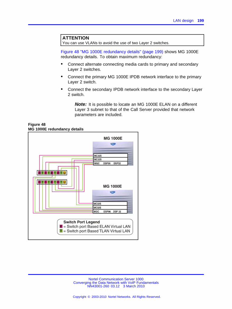
LAN design 199
ATTENTIONYou can use VLANs to avoid the use of two Layer 2 switches.
Figure 48 "MG 1000E redundancy details" (page 199) shows MG 1000Eredundancy details. To obtain maximum redundancy:
• Connect alternate connecting media cards to primary and secondaryLayer 2 switches.
• Connect the primary MG 1000E IPDB network interface to the primaryLayer 2 switch.
• Connect the secondary IPDB network interface to the secondary Layer2 switch.
Note: It is possible to locate an MG 1000E ELAN on a differentLayer 3 subnet to that of the Call Server provided that networkparameters are included.
Figure 48MG 1000E redundancy details
Nortel Communication Server 1000Converging the Data Network with VoIP Fundamentals
NN43001-260 03.12 3 March 2010
Copyright © 2003-2010 Nortel Networks. All Rights Reserved.
.

200 Planning and engineering
Communication Server 1000E Campus redundancyFigure 49 "Campus redundancy : Layer 2 switch configuration" (page200) and Figure 50 "Campus redundancy : Side 0 with VLANs"(page 201) show campus redundancy for a Communication Server1000E system. If you plan to use campus redundancy, follow theserecommendations:
• To implement the campus redundant Layer 2 switch configuration,Virtual LANs are required on the Layer 2 switches.
• The Layer 2 switch ports that connect the HSP network interfaces mustbe in a completely isolated VLAN.
• Group the two gigabit fiber optic links using a multilink trunk protocol.
Enable Spanning Tree Protocol Fast Port on all switch ports and themultilink trunk, or disable Spanning Tree Protocol on all switch ports.
Figure 49Campus redundancy : Layer 2 switch configuration
Nortel Communication Server 1000Converging the Data Network with VoIP Fundamentals
NN43001-260 03.12 3 March 2010
Copyright © 2003-2010 Nortel Networks. All Rights Reserved.
.

Zone Based Dialing plan 201
Figure 50Campus redundancy : Side 0 with VLANs
ATTENTIONIn Figure 50 "Campus redundancy : Side 0 with VLANs" (page 201), Side 0 andSide 1 are considered to be identical.
For detailed information about campus redundancy, see SystemRedundancy Fundamentals (NN43001-507) ().
Zone Based Dialing planThe following components interact with this feature:
• CLID
• Features which depend on CLID
• DAPC
• Keymap download
• LNR
• ISDN (new ZBD IE)
• OCS
• Tone Table
• Call Pilot
Nortel Communication Server 1000Converging the Data Network with VoIP Fundamentals
NN43001-260 03.12 3 March 2010
Copyright © 2003-2010 Nortel Networks. All Rights Reserved.
.

202 Planning and engineering
• Call Park
• Remote Call Forward
• BSF
• GR
• Pre:translation
• EM
• VNR
• Call Forward
• Call Transfer
• Conference
• PD/Corp directory
• ESA
Feature dependencies and restrictionsThe new Zone Based Dialing plan (ZBD) IE is created to send the ZBDspecific data inside of ISDN messages.
Use the zone based AC1/AC2/INTC/NATC parameters instead of theconfiguration in the route and customer data block for the zone:based DialAccess Prefix on CLID (DAPC) feature. Therefore, for incoming inter:sitecalls, access prefixes from numbering zone parameters are received andinserted to the beginning of CLID; DAPC is enabled per set basis (CLSDAPA), for example, for international call AC1+INTC is inserted.
You must configure 7:digit DN for a ZBD feature key and you can set thesite prefix from 2 to 4 digits.
The 7:digit DN is sent to TPS. Use the 7:digit DN to generate a user IDthat implements features such as PD/RL/CL. The site prefix is cut off onthe TPS side before sending it to the set in the UNISTIM message.
Overlay 10, 11Overlays 10 and 11 are modified to store numbering zones for sets (IP,TDM, analog, UEXT, PCA) in protected unit blocks.
Overlay 12Overlays 12 is modified to store numbering zones for an attendant in aprotected unit block.
Overlay 15The new prompts, ZBD and DIALPLAN, are added to LD 15.
Nortel Communication Server 1000Converging the Data Network with VoIP Fundamentals
NN43001-260 03.12 3 March 2010
Copyright © 2003-2010 Nortel Networks. All Rights Reserved.
.

Zone Based Dialing plan 203
The ZBD prompt enables or disables the ZBD feature. It has a yes or novalue. :
Use the DIALPLAN prompt for DN/CLID processing. It inlcudes PUB andPRV values. If the DIALPLAN prompt is set to PUB, then the appropriateE164 CLID is displayed on a terminating set. If it is set to PRV then a7:digit DN/CLID is displayed.
Overlay 20Overlay 20 is modified to print out numbering zones for a set.
Overlay 21Overlay 21 is modified to print out the status of the ZBD feature, enabledor not. Also, the configured value for DIALPLAN is displayed in the ZBDprompt group.
Overlay 22Overlay 22 is modified to print out the status of the ZBD package.
Overlay 43ZBD databases are dumped into /u/db/ during EDD and are also backedup to the secondary device. ZBD databases are restored to /u/db/ duringdatabase restore.
Overlay 81Overlay 81 is modified to print out information and count configured setsfor specified numbering zones.
Overlay 83Overlay 83 is modified to print out numbering zone for configured sets.
Overlay 117This overlay is modified to add the following commands:
• configure/change/delete/print numbering zones
• configure/change/delete/print numbering zone parameters
• configure/change/delete/print ZFDP and ZDID entries
• change designator for numbering zones
Feature impact on planning and engineering tasksYou must reconfigure sets to 7:digit DN, which consist of site prefix andshort DN.
You must configure the network to guarantee an 80 millisecond (ms) roundtrip delay requirement for signaling between Communication Server 1000and SMG.
Nortel Communication Server 1000Converging the Data Network with VoIP Fundamentals
NN43001-260 03.12 3 March 2010
Copyright © 2003-2010 Nortel Networks. All Rights Reserved.
.

204 Planning and engineering
Vacant Number Routing featureEnhancements are performed for a VNR call over IP because IPaccessible users are typically a subset of the total set of users. If a VNRcall over IP is rejected due to a specific cause, for example Cause x.If Cause x is one of the MCDN Alternate Routing (MALT) configurablecauses provided in Element Manager (EM) and the user has selectedCause x to perform MALT, alternate routing is performed for the call atthe Call Server. The feature impacts the treatment provided to the VNRcall. The treatment is based on the previous and current rejection cause.The best treatment is provided so that the user gets the correct reason ofrejection for the VNR call. MALT is performed for the existing six causes,and for any of the added ten provisional causes if the call clears from theIP network with a Do MALT indication."
This feature is an enhancement on the existing VNR feature thus you mustenable the VNR feature package for the feature to work properly. For moreinformation about VNR enhancements, see IP Peer Networking Installationand Commissioning (NN43001-313).
Dialing planWhen a number is dialed, the Call Server determines whether the callednumber is internal or external to the branch office. If internal, the systemterminates the call on the appropriate terminal. If external, the systemroutes the call in one of two ways:
• Uniform Dialing Plan (UDP) or Coordinated Dialing Plan (CDP) routesthe call to the proper trunk group.
• Vacant Number Routing (VNR) routes the call to a Virtual Trunk.
After the call is sent over the IP network, the call is routed to the MG1000B Core, which uses the Network Routing Service (NRS) to route thecall. In a SIP network, the Redirect Server translates the address froma telephone number to a SIP URI, and authorizes the call. In an H.323network, the H.323 Gatekeeper translates the address from a telephonenumber to an IP address, and authorizes the call.
Specific dialing plan configuration is required for IP Phones to properlyselect a main office or branch office that provides access to the PSTN forthe originating IP Phone. A common configuration might be:
• Branch Users select the MG 1000B PSTN for local calls.
• Main office users select the main office PSTN for local calls.
• All users select either the main office or MG 1000B PSTN forlong:distance calls to minimize toll charges.
Nortel Communication Server 1000Converging the Data Network with VoIP Fundamentals
NN43001-260 03.12 3 March 2010
Copyright © 2003-2010 Nortel Networks. All Rights Reserved.
.

Dialing plan 205
However, this configuration represents only one way that the dialing plancould be configured. PSTN calls can be routed according to the point oforigin (main office or branch office) and/or the desired destination, and canselect trunks at the main office, branch office, or other branch offices asrequired. Therefore, the user can route calls to gateways that minimizelong:distance costs, minimize bandwidth usage, or meet other criteria.
On:net dialing plan optionsDepending upon customer dialing preferences and configurationmanagement requirements, many on:net dialing plans are available:
• Coordinated Dialing Plan (CDP) — each location is allocated one ormore Steering Codes that are unique within a CDP domain.
• Uniform Dialing Plan (UDP) — each location is assigned a LocationCode (LOC). Each telephone has a unique Directory Number (DN).
• Group Dialing Plan (GDP) — each group has an LOC that has to bedialed from outside the group as a prefix to the group CDP. Membersin the group may dial only the CDP number. Effectively, GDP is acombination of CDP and UDP.
• Transferable Directory Numbers (TNDN) — each user is given aunique DN, that does not change even if it moves to a different CallServer. The NRS keeps track of each TNDN in the network so that itknows to which endpoint (Call Server or MG 1000B Core) to returnwhen asked to resolve a TNDN address.
For more information, see Dialing Plans Reference (NN43001-283) ().
Nortel recommends that customers use Coordinated Dialing Plan (CDP)between the main office and its branch offices since it enables all users, atthe main office or Branch Office, to call each other using just an extensionnumber. CDP enables consistent dialing between the main office andMG 1000B IP Phones and devices. For more information about on:netconfiguration examples, see Branch Office Installation and Commissioning(NN43001-314) ().
Off:net dialing planWhen dialing to the PSTN, the Call Server determines that the calldestination is off:net by analyzing the digits that must be pre:configured atmajor Call Servers in the network.
If routed over a Virtual Trunk, a request is sent to the NRS to determinethe location of public E.164 numbers. The NRS is configured with a listof potential alternate routes that can be used to reach a certain dialednumber. Each route is configured with a unique route cost to determinethe least:cost route.
Nortel Communication Server 1000Converging the Data Network with VoIP Fundamentals
NN43001-260 03.12 3 March 2010
Copyright © 2003-2010 Nortel Networks. All Rights Reserved.
.

206 Planning and engineering
The NRS replies with the address information for E.164 numbers andprovides a list of alternative SIP or H.323 endpoints, sorted by cost. If aterminating endpoint resource is busy when a call attempt is made, theoriginating endpoint tries the next alternative. If no alternative is availableover the IP network, the originating endpoint steps to the next entry onits route list, which could be a TIE or PSTN alternate route. For moreinformation about off:net configuration examples, see Signaling Server IPLine Applications Fundamentals (NN43001-125). ()
RoutingThe following describes routing of Branch Office calls.
Branch user call to an MG 1000B PSTNThe Branch User telephone is registered at the main office. The BranchUser telephones are physically located at the Branch Office, so routing oflocal PSTN calls back to the Branch Office is essential, even if they areregistered with the main office.
Branch Office behavior of the Branch User telephones at the main office isconfigured by setting Branch Office zone characteristics through LD 117at the main office
Routing incoming calls from an MG 1000B PSTN to an MG1000B telephone (DID call)If the DN is valid and can terminate, call termination at the Branch Office istreated differently for IP Phones and non:IP Phones, as follows:
• IP Phones — if the telephone is registered to the MG 1000B CP PM(Local Mode), the call is terminated locally. If the telephone is notregistered to the MG 1000B CP PM (Normal Mode), the call is routedthrough a Virtual Trunk to the main office.
• Non:IP Phones — all are terminated locally (within the Branch Office).
If the DN is not valid, the number is considered vacant by the MG 1000BCP PM, and VNR is used to route the call to the NRS for resolution.
SIP/H.323 zonesIn a SIP/H.323 network, each NRS controls one SIP/H.323 zone. Eachzone can consist of many SIP/H.323 endpoints. If a call terminatesbeyond the call originator zone, the Redirect Server or H.323 Gatekeeperof the called party zone provides the endpoint information to set up theconnection.
You can divide a system into several zones. You can also divide acustomer within a system into different zones. It is more common to assignone zone to one system and one customer.
Nortel Communication Server 1000Converging the Data Network with VoIP Fundamentals
NN43001-260 03.12 3 March 2010
Copyright © 2003-2010 Nortel Networks. All Rights Reserved.
.

Distributed Media Gateway 1000E 207
Distributed Media Gateway 1000EA Media Gateway 1000E (MG 1000E) can be physically distributed withinan Enterprise IP network. The gateway can be configured in a differentsubnet than the Call Server providing the following criteria are met:
• The Signaling Servers remain in the same ELAN subnet as the CallServer.
• Distributed Media Gateway 1000E does not support Media Card MC32.
• The TPS must be disabled for Media Cards (MC32S) in a differentsubnet.
• Packet loss on the Enterprise IP network must be less than 0.5% (0%packet loss is recommended).
• Round:trip delay between Call Server and MG 1000E must be lessthan 80 ms.
• Use of a QoS mechanism is highly recommended and assists inmeeting packet loss and latency requirements.
Each ELAN subnet must be configured in a separate node and a callserver can be configured to use multiple nodes. A node is a collection ofsignaling servers, media cards, or a combination of both. A node can becomposed of a single media card or a single signaling server. A node musthave one Leader; the rest of the node is configured as followers. Eachsubnet can have more than one node, but nodes cannot span subnets.The Leader uses the Bootstrap Protocol (BOOTP) to supply IP addressesto the followers in its node.
A media card or server configured as a follower, must be in the sameELAN broadcast domain as the Leader. If the follower is not in the sameELAN broadcast domain as the Leader, it must be configured in a differentnode. If the follower is the only member of the node, it must be configuredas the Leader.
A follower broadcasts a BOOTP request over the ELAN to obtain availableIP addresses. A Leader that has configured the MAC address of thefollower in its BOOTP tables responds to the BOOTP request from thefollower with the IP addresses. The follower stores the IP addresses anduses them to boot. The follower does not boot if the BOOTP requestfails. If the BOOTP request fails and the follower has previously madecontact with a Leader, it boots using the stored IP addresses from the lastsuccessful response.
The MGC and SSC, which control the cabinet that contains a media card,do not use BOOTP so they do not have the same restrictions as the mediacard. The SSC and MGC are not part of a node and cannot be used as aLeader.
Nortel Communication Server 1000Converging the Data Network with VoIP Fundamentals
NN43001-260 03.12 3 March 2010
Copyright © 2003-2010 Nortel Networks. All Rights Reserved.
.

208 Planning and engineering
Fax and Modem pass throughThe Fax/Modem pass through feature provides a modem pass throughallowed (MPTA) class of service (CoS) for an analog phone TN. MPTACLS dedicates an analog phone TN to a modem or a Fax machineterminal. A connection that initiates from the dedicated TN, and/or callsthat terminate at the dedicated TN through a Digital Signal Processor(DSP), use a G711 NO VAD codec on the Call Server.
Modem Pass through is a specific configuration of a G.711 VoIPchannel that improves modem performance compared to standard VoIPconfiguration. Auto switch to Voice Band Data (VBD) is a feature of theDSP; the DSP monitors the data stream to distinguish between voice anddata calls. The DSP reconfigures to modem pass through mode when itdetermines the call is a modem call.
The DSP mode on the Mindspeed DSP (MC32S/DB96/DB32) forMPTA:MPTA fax/modem call will display "ModemPT" in dspMode field ofvgwShow command. Where as for Teology DSP (ITGSA) it will displays"PassThrough".
For modem calls between Communication Server 1000 systems connectedby analog and digital trunks, you must configure MPTA CLS on the CallServer of each Communication Server 1000 system for analog unitsconnected to modems. MPTA CLS configuration is necessary becausethe call setup negotiation is not done end:to:end as it is for virtual trunks.If the analog unit on one Call Server uses MPTA CLS and the analog uniton the other Call Server uses modem pass through denied MPTD CLS,the modem call fails.
When MPTA CLS is configured on a TN, the T.38 protocol is no longersupported for that particular TN. Any call setup with an analog phone TNthat has MPTA configured must use G711 Codec exclusively, as this is theonly codec available for making calls using this TN. G711 codec is presentby default in the DSP configuration. To ensure proper functioning of theMPTA CLS, the Enable Modem/Fax pass through mode check box mustbe selected in the Gateways section of Element Manager. This check boxis selected by default in Element Manager. To enable SG3 fax calls overTeology DSP, the Enable V.21 FAX tone detection check box in ElementManager must be selected. For SMC and MC32S cards, this setting isavailable in the Voice Gateway and IP phone codec profile section in theNodes summary page. In the modem pass through mode of operation,the DSP state is displayed as MPT on the MGC and MC32S cards andas PassThru on SMC cards.
Nortel Communication Server 1000Converging the Data Network with VoIP Fundamentals
NN43001-260 03.12 3 March 2010
Copyright © 2003-2010 Nortel Networks. All Rights Reserved.
.

Fax and Modem pass through 209
MPTA CLS is not supported through Telephony Manager (TM) and BasicClient Configuration (BCC). BCM 50 only supports modem pass throughover G.711 in Release M50R3. The packet interval for G.711 codec is setto 20 ms in MPT.
The maximum speed supported for modem and fax is 33.6 kbit/s. This limitis imposed by the analog line card.
MPT allows Communication Server 1000 to support the following:
• modem pass through
• Super G3 (SG3) fax at V.34 (33.6 Kbit/s)
• V.34 rate (33.6 kbit/s) modems
• Fax machines that support V.17, V.27, V.29, and V.34 protocols
Note: MPT CLS is not be supported on IP trunks When the TN on theCommunication Server 1000 is configured with MPTA CLS, it supportsV.17, V27 and V29 Fax calls. However, the DSP mode is “FaxBegin,” not“ModemPT”. The MPTA CLS forces calls originated or terminated on theTN to use the G.711 NO VAD Codec. This codec selection supersedes theexisting bandwidth management strategy on the Communication Server1000. Note: When a Communication Server 1000E is inter:connectedwith a system from a different vendor, the modem pass through featureworks if the third party system supports the modem pass through mode ofoperation. The Voice Gateway application displays different Auto:switchstates (ModemPT, Passthru) in the dspMode field of the vgwShowcommand, based on tones detected by the DSP. These tones aregenerated by modem and fax machines connected in the TDM domain.The Voice Gateway application does not control Auto:switch states duringfax and modem calls, and the dspMode reports tone indications from DSP.The Mindspeed DSP sends tone detection events to the host processorand changes to Modem Passthough and Pass:through auto:switch states(with or without Redundancy), based on the tones detected, as it isconfigured in Auto:switch mode.
For interface commands, responses, and definitions for MPT, see Table 34"Interface commands and responses" (page 210).
Nortel Communication Server 1000Converging the Data Network with VoIP Fundamentals
NN43001-260 03.12 3 March 2010
Copyright © 2003-2010 Nortel Networks. All Rights Reserved.
.

210 Planning and engineering
Table 34Interface commands and responses
Command prompt User response Description
CLS MPTA Turn on the MPT feature.
CLS MPTD Turn off the MPT feature.
Note: CLS MPTA and MPTD is included in LD 10 for analog line cardunits.
MPTA to MPTA and MPTA to MPTD fax/modem calls succeed overthe G.711 codec in ModemPT DSP mode. However; MPTD to MPTDmodem calls fail. MPTD to MPTD fax calls succeed (best effort) overG.711 if the Enable Modem/Fax pass through mode and Enable V.21FAX tone detection options are set to ON in the gateway. If the EnableModem/Fax pass through mode is unchecked, the fax call goes over theT.38 codec. The T.38 fax codec is recommended for fax calls over SIPand H323 trunks. To select the T.38 fax codec, the analog line units atboth originating and terminating systems must be set to MPTD CLS.
For information about feature packaging requirements, see Table 35"Feature packaging requirements" (page 210).
Table 35Feature packaging requirements
Packagemnemonic
Packagenumber
Packagedescription
Package type(new, existing,or dependency)
Applicablemarket
Softswitch 402 Identifies a softswitch system. Existing All
IPMG 403 Identifies a system equippedwith IPMGs.
Existing All
Modem trafficCommunication Server 1000E supports modem traffic in acampus:distributed network with the following characteristics:
• Media card configuration:
— G.711 codec
— 20 ms packet size
• one:way delay less than 5 ms
• low packet loss
• V.34 rate (33.6 kbit/s)
Nortel Communication Server 1000Converging the Data Network with VoIP Fundamentals
NN43001-260 03.12 3 March 2010
Copyright © 2003-2010 Nortel Networks. All Rights Reserved.
.

Fax and Modem pass through 211
ATTENTIONPerformance degrades significantly with packet loss (must be less than 0.5%)and when the delay (round trip) is greater than 50 msec and mean jitter isgreater than 5msec.
ATTENTIONNortel has conducted extensive but not exhaustive tests of modem:to:modemcalls, data transfers, and file transfers between a Communication Server 1000Eand MG 1000E, using Virtual Trunks and PRI tandem trunks. While all testshave been successful, Nortel cannot guarantee that all modem brands willoperate properly over all G.711 Voice over IP (VoIP) networks. Before youdeploy modems, test the modem brand within the network to verify reliableoperation. Contact your system supplier or your Nortel representative for moreinformation.
Sample system layoutFigure 51 "Communication Server 1000S sample system layout" (page211) shows a sample system layout for the Communication Server 1000S.
Figure 51Communication Server 1000S sample system layout
Nortel Communication Server 1000Converging the Data Network with VoIP Fundamentals
NN43001-260 03.12 3 March 2010
Copyright © 2003-2010 Nortel Networks. All Rights Reserved.
.

212 Planning and engineering
Address and connection tablesThe following tables can be used to record address and connectionrecords for:
• system servers — use Table 36 "System servers addresses andconnections" (page 212)
• Media Gateway 1000T (MG 1000T) — Table 37 "MG 1000T addressesand connections" (page 213)
• applications — Table 38 "Application addresses and connections"(page 216)
System server addresses and connections Use Table 36 "Systemservers addresses and connections" (page 212) to record system serveraddresses and connections.
Table 36System servers addresses and connections
System IP addresses
Node IP address:
Primary NRS IP address:
Alternate NRS IP address:
SNMP NRS IP address:
Call Server 0 (ELNK)
ELAN network interface
IP address:
Subnet Mask:
Default Gateway:
Call Server 1 (ELNK)
ELAN network interface
IP address:
Subnet Mask:
Default Gateway:
Signaling Server
ELAN network interface
IP address:
Subnet Mask:
Default Gateway:
Nortel Communication Server 1000Converging the Data Network with VoIP Fundamentals
NN43001-260 03.12 3 March 2010
Copyright © 2003-2010 Nortel Networks. All Rights Reserved.
.

Fax and Modem pass through 213
Table 36System servers addresses and connections (cont’d.)
System IP addresses
TLAN network interface
IP address:
Subnet Mask:
Default Gateway:
IPMG SSC
ELAN network interface
IP address:
Subnet Mask:
Default Gateway:
Voice Gateway Media Card
ELAN network interface
MAC address:
IP address:
Subnet Mask:
Default Gateway:
TLAN network interface
Node IP address:
IP address:
Subnet Mask:
Default Gateway:
Media Gateway 1000T addresses and connections Use Table 37"MG 1000T addresses and connections" (page 213) to record MG 1000Taddresses and connections.
Table 37MG 1000T addresses and connections
System IP addresses
Node IP address:
Primary NRS IP address:
Alternate NRS IP address:
SNMP NMS IP address:
SSC 0
ELAN network interface
Nortel Communication Server 1000Converging the Data Network with VoIP Fundamentals
NN43001-260 03.12 3 March 2010
Copyright © 2003-2010 Nortel Networks. All Rights Reserved.
.

214 Planning and engineering
Table 37MG 1000T addresses and connections (cont’d.)
IP address:
Subnet Mask:
Default Gateway:
IPM 1 network interface
IP address:
Subnet Mask:
IPM 2 network interface
IP address:
Subnet Mask:
IPM 3 network interface
IP address:
Subnet Mask:
IPM 4 network interface
IP address:
Subnet Mask:
SSC 1
ELAN network interface
IP address:
Subnet Mask:
Default Gateway:
IPR 1 network interface
MAC address:
IP address:
Subnet Mask:
SSC 3
ELAN network interface
IP address:
Subnet Mask:
Default Gateway:
IPR 3 network interface
MAC address:
IP address:
Subnet Mask:
Nortel Communication Server 1000Converging the Data Network with VoIP Fundamentals
NN43001-260 03.12 3 March 2010
Copyright © 2003-2010 Nortel Networks. All Rights Reserved.
.

Fax and Modem pass through 215
Table 37MG 1000T addresses and connections (cont’d.)
SSC 2
ELAN network interface
IP address:
Subnet Mask:
Default Gateway:
IPR 2 network interface
MAC address:
IP address:
Subnet Mask:
SSC 4
ELAN network interface
IP address:
Subnet Mask:
Default Gateway:
IPR 4 network interface
MAC address:
IP address:
Subnet Mask:
Signaling Server
ELAN network interface
IP address:
Subnet Mask:
Default Gateway:
TLAN network interface
Node IP address:
IP address:
Subnet Mask:
Default Gateway:
Voice Gateway Media Card
ELAN network interface
MAC address:
IP address:
Subnet Mask:
Nortel Communication Server 1000Converging the Data Network with VoIP Fundamentals
NN43001-260 03.12 3 March 2010
Copyright © 2003-2010 Nortel Networks. All Rights Reserved.
.

216 Planning and engineering
Table 37MG 1000T addresses and connections (cont’d.)
Default Gateway:
TLAN network interface
Node address:
IP address:
Subnet Mask:
Default Gateway:
Application addresses and connections Use Table 38 "Applicationaddresses and connections" (page 216) to record application addressesand connections.
Table 38Application addresses and connections
CallPilot Server
ELAN network interface
IP address:
Subnet Mask:
Default Gateway:
CLAN network interface
IP address:
Subnet Mask:
Default Gateway:
SSCS
ELAN network interface
IP address:
Subnet Mask:
Default Gateway:
CLAN network interface
IP address:
Subnet Mask:
Default Gateway:
TM Server
network interface
IP address:
Nortel Communication Server 1000Converging the Data Network with VoIP Fundamentals
NN43001-260 03.12 3 March 2010
Copyright © 2003-2010 Nortel Networks. All Rights Reserved.
.

DHCP configuration 217
Table 38Application addresses and connections (cont’d.)
Subnet Mask:
Default Gateway:
DHCP configurationThis section provides general guidelines on how to configure a host with aDynamic Host Configuration Protocol (DHCP) server to support Nortel IPPhones 200x and the IP Softphone 2050.
If you are not familiar with DHCP, Nortel recommends that you readRequest for Comments (RFC) 2131 Dynamic Host Configuration Protocol,RFC 1533 DHCP Options and BOOTP Vendor Extensions, and the Helpmanual for the DHCP server on the host.
For a general overview about DHCP server technology, see “DHCPsupplemental information” (page 419)
IP PhonesIP Phones 200x and the IP Softphone 2050 are VoIP telephones thatfunction as a telephone to the Meridian 1 and Communication Server 1000systems. The IP Phoneencodes voice as binary data and packetizes thedata for transmission over an IP network to the Voice Gateway Media Cardor to another IP Phone.
The Nortel IP Phonecan act as a DHCP client in one of two modes:
• partial DHCP mode
• full DHCP mode
All the configuration parameters for the IP Phonecan be entered manually.Each IP Phonerequires network configuration parameters, Connect Serverparameters, IP Telephony node ID, and Virtual TN. If there are a numberof IP Phones to configure, manual configuration is time:consuming andprone to error. Using full or partial DHCP to automatically configure theIP Phones is more efficient and flexible and ensures that you use currentinformation.
Nortel Communication Server 1000Converging the Data Network with VoIP Fundamentals
NN43001-260 03.12 3 March 2010
Copyright © 2003-2010 Nortel Networks. All Rights Reserved.
.

218 Planning and engineering
Partial DHCP modeWhen the IP Phone is configured to operate in partial DHCP mode, theDHCP server needs no special configuration to support IP Phones. TheIP Phone receives the following network configuration parameters fromthe DHCP server:
• IP address configuration for the IP Phone
• subnet mask for the IP PhoneIP address
• default gateway for the IP PhoneLAN segment
ATTENTIONIn partial DHCP mode, the Connect Server parameters, (node ID and VirtualTN) must be entered manually.
Full DHCP modeIn full DHCP mode, the DHCP server requires special configuration. TheIP Phone obtains network configuration parameters and Connect Serverconfiguration parameters from specially:configured DHCP servers.
The following parameters are provided for the primary and secondaryConnect Servers:
• Connect Server IP address — for IP Line 4.5, the Connect Server IPaddress is the IP Telephony node IP address.
• port number = 4100
• command value = 1; identifies the request to the Connect Server asoriginating from an IP Phone
• retry count = 10 (typically)
ATTENTIONThe IP Telephony node ID and Virtual TN must always be configured manuallyeven in full DHCP mode.
802.1Q configuration of IP Phones802.1Q VLAN support is configured using the display interface of the IPPhones during the initial configuration procedure of the IP Phone.
For 802.1Q configuration procedures of the IP Phones, see IP PhonesFundamentals (NN43001-368) ().
Nortel Communication Server 1000Converging the Data Network with VoIP Fundamentals
NN43001-260 03.12 3 March 2010
Copyright © 2003-2010 Nortel Networks. All Rights Reserved.
.

DHCP configuration 219
Configuring the DHCP server to support full DHCP modeThe DHCP capability of the IP Phoneenables the telephone to receivenetwork configuration parameters and specific Connect Server parameters.This section describes the IP Phoneunique class identifier and requestednetwork configuration and Connect Server parameters for automaticconfiguration.
IP Phone class identifierThe IP Phoneis designed with a unique class identifier that the DHCPserver can use to identify the telephone. All Nortel IP Phones use thesame text string: Nortel:i2004:A. The ASCII string is sent inside the ClassIdentifier option of the IP PhoneDHCP messages.
The DHCP server also includes the text string in its responses tothe IP PhoneDHCP client to notify the IP Phonethat the server is IPPhone:aware, and that it is safe to accept the server offer. The stringappears in the beginning of a list of specific Voice Gateway Media Cardinformation that the IP PhoneDHCP client requests.
When the DHCP server is configured to recognize the IP Phoneas aspecial class, the DHCP server can treat the IP Phonedifferently thanother DHCP clients. DHCP host configuration parameters can then begrouped by class to supply only information relevant to the IP PhoneDHCPclient, such as the Connect Server parameters. The administrator canalso design the network according to the client class; if necessary, makingmaintenance easier.
Depending on the capabilities and limitations of the DHCP server used,and the design of the network, some advanced functions are not available.
Requested network configuration parametersUsing full DHCP mode, an IP Phone:aware DHCP server canautomatically configure Nortel IP Phones by requesting a list of ConnectServer configuration parameters. The IP Phoneuses DHCP to request andreceive the information.
IP Phones that operate in partial DHCP mode can receive an IP addressfrom any DHCP server. In full DHCP mode, the server must be configuredto respond to the request for the vendor:specific encapsulated options.
Table 39 "IP Phone network configuration parameters" (page 220) liststhe network configuration parameters requested by the IP Phonein theParameter Request List option (Option Code 55) in the DHCPDISCOVERand DHCPREQUEST messages. The DHCPOFFER and the DHCPACKreply messages from the DHCP server must contain the options in Table39 "IP Phone network configuration parameters" (page 220).
Nortel Communication Server 1000Converging the Data Network with VoIP Fundamentals
NN43001-260 03.12 3 March 2010
Copyright © 2003-2010 Nortel Networks. All Rights Reserved.
.

220 Planning and engineering
Table 39IP Phone network configuration parameters
Parameters requested by IP Phone(Option Code 55)
DHCP serverresponse: Option
Code
Subnet mask — the client IP subnet mask 1
Router/gateways — the IP address of the client’sdefault gateway (not required in DHCPOFFER in IPPhoneFirmware 1.25 and later for compatibility withNovell DHCP server)
3
Lease time — implementation varies according toDHCP server
51
Renewal time — implementation varies according toDHCP server
58
Rebinding interval — implementation varies accordingto DHCP server
59
IP Line site:specific or vendor:specific encapsulated/site options.
43, 128, 144,157, 191, 251
The first five parameters in Table 39 "IP Phone network configurationparameters" (page 220) are standard DHCP options and have predefinedoption codes. The last parameter is for Voice Gateway Media Cardinformation, which does not have a standard DHCP option. The serveradministrator must define a vendor:encapsulated and/or site:specific optionto transport this information to the IP Phone.
This nonstandard information includes the unique string that identifiesthe IP Phoneand the Connect Server parameters for the primary andsecondary servers. The IP Phonemust receive the Connect Serverparameters to connect to the IP Telephony node.
The administrator must use one of the site:specific or vendor:encapsulatedoption codes to implement the Voice Gateway Media Card information.This user:defined option can then be sent as it is, or encapsulated ina Vendor Encapsulated option with Option Code 43. The method useddepends on the DHCP server capabilities and the options are already inuse by other vendors.
The IP Phonerejects any DHCPOFFER and DHCPACK messages thatdo not contain the following options:
• a router option — IP Phonerequires a default gateway (router)
• a subnet mask option
• a vendor:specific or site:specific option
Nortel Communication Server 1000Converging the Data Network with VoIP Fundamentals
NN43001-260 03.12 3 March 2010
Copyright © 2003-2010 Nortel Networks. All Rights Reserved.
.

DHCP configuration 221
ATTENTIONThe vendor:specific Option Code is 43. A Windows NT DHCP Server (up toSR4) supports only 16 octets of data for the vendor:specific option, which isinsufficient to support the minimum length of the IP Phone:specific string.If you use a Windows NT DHCP Server, select the Site Specific option toaccommodate the IP Phone:specific string.
The site:specific options are all DHCP options between 128 (0x80) and 254(0xFE). These options are reserved for site:specific use by the DHCP RFCs.
Format for IP Phone DHCP Class Identifier optionAll Nortel IP Phones fill in the Class ID option of the DHCPDISCOVER andDHCPREQUEST messages with the null:terminated, ASCII:encoded stringNortel:i2004:A, where A identifies the version number of the informationformat of the IP Phone.
The Class Identifier Nortel:i2004:A must be unique in the DHCP serverdomain.
Format for IP Phone DHCP encapsulated Vendor SpecificOptionThe Nortel:specific, encapsulated Vendor Specific Option for IP Phones200x and the IP Softphone 2050 must be encapsulated in a DHCPvendor:specific option (see RFC 1533) and returned by the DHCP serveras part of each DHCPOFFER and DHCPACK message for the IP Phonetoaccept these messages as valid. The IP Phoneextracts the relevantinformation from this option and uses it to configure the Connect ServerIP address, the port number (4100), a command value (1), and the retrycount for the primary and secondary Connect Servers.
Either this encapsulated Vendor Specific Option or a similarly encodedsite:specific option must be sent. The DHCP server must be configured tosend one or the other but not both. The choice of using the vendor:specificor the site:specific option is provided to enable Windows NT DHCP serversto support the IP Phone. Windows NT servers do not properly implementthe Vendor Specific Option; and, as a result, Windows NT implementationsmust use the Site Specific version.
The format of the encapsulated Vendor Specific option is Type, Length,and Data.
Type (1 octet): There are five types:
• 0x80 (Site Specific option 128)
• 0x90 (Site Specific option 144)
• 0x9d (Site Specific option 157)
Nortel Communication Server 1000Converging the Data Network with VoIP Fundamentals
NN43001-260 03.12 3 March 2010
Copyright © 2003-2010 Nortel Networks. All Rights Reserved.
.

222 Planning and engineering
• 0xbf (Site Specific option 191)
• 0xfb (Site Specific option 251)
The choice of five types enables the IP Phoneto work one or more valuesalready in use by a different vendor. Select one value for the Type byte.
Length (1 octet) The Length value is variable. Count only the number ofoctets in the data field (see the following section).
Data (variable number of octets) The Data field contains anASCII:encoded character string as follows:
Nortel:i20xx:A,iii.jjj.kkk.lll:ppppp,aaa,rrr;iii.jjj.kkk.lll:ppppp,aaa,rrr.
This string can be NULL:terminated, although the NULL is not requiredfor parsing.
The parameters for the data field are described in Table 40 "Data fieldparameters" (page 222) and in the list following the table.
Table 40Data field parameters
Parameter Description
Nortel:i2004:A Uniquely identifies the Nortel option, and is a response from a server that canprovide the correct configuration information to the IP Phones 200x and the IPSoftphone 2050.
iii.jjj.kkk.lll:ppppp Identifies IP address and port number for the server(ASCII:encoded decimal)
aaa Identifies action for server(ASCII encoded decimal, range 0–255)
rrr Identifies the retry count for server(ASCII encoded decimal, range 0–255)
comma (,) ASCII "," separates fields.
colon (:) ASCII ":" separates the IP address of the bootstrap server node IPaddress from the Transport Layer port number.
semicolon (;) ASCII ";" separates the Primary from Secondary bootstrap serverinformation. The bootstrap server is the Active Leader of the IPTelephony node.
period (.) ASCII "." signals end of structure.
• "aaa" and "rrr" are ASCII encoded decimal numbers with a range of 0– 255. They identify the Action Code and Retry Count, respectively,for the associated TPS server. They are stored as one octet (0x00 –
Nortel Communication Server 1000Converging the Data Network with VoIP Fundamentals
NN43001-260 03.12 3 March 2010
Copyright © 2003-2010 Nortel Networks. All Rights Reserved.
.

DHCP configuration 223
0xFF) in the IP Phone. These fields must be no more than three digitslong.
• Two Connect Servers and an optional external application server(XAS) can be specified in the DHCP string:
— The first Connect Server is always considered primary.
— The second Connect Server is always considered secondary.
— An optional XAS can be appended to the Connect Servers.
• The string enables the configuration of information for two ConnectServers. One Connect Server exists for each IP node. In the typicalsystem configuration of a single IP node, only the primary ConnectServer is required. In this case, the primary Connect Server string mustend with a period (.) instead of a semicolon (;). For example:
Nortel:i2004:A,iii.jjj.kkk.lll:ppppp,aaa,rrr.
If the secondary Connect Server portion of the string is specified, thenthe string information is typically the same as the primary ConnectServer information. For example:
Nortel:i2004:A,iii.jjj.kkk.lll:ppppp,aaa,rrr;iii.jjj.kkk.lll:ppppp,aaa,rrr.
When the Enhanced Redundancy for IP Line Nodes feature is used,two different Connect Server strings can be configured, separated witha semi:colon (;). This enables the telephone to register to two differentnodes. For more information about the Enhanced Redundancy forIP Line Nodes feature, see Signaling Server IP Line ApplicationsFundamentals (NN43001-125) ().
• Action code values include:
— 0 — reserved
— 1 — UNIStim Hello (currently this type is the only valid choice)
— 2 to 254 — reserved
— 255 — reserved
• The ASCII:encoded decimal numbers iii.jjj.kkk.lll represent the IPaddress of the server. They do not need to be three digits longbecause the (. ) and (: ) delimiters guarantee parsing. For example,001, 01, and 1 would be parsed correctly and interpreted as value 0x01internal to the IP Phone. These fields must be no longer than threedigits.
• The port number in ASCII:encoded decimal is ppppp.. It does notneed to be five digits long as the colon (:) and comma (,) delimitersguarantee parsing. For example, 05001, 5001, 1, and 00001 wouldbe parsed correctly and accepted as correct. The valid range is 0 to65535 (stored internally in the IP Phoneas hexadecimal in a range of 0to 0xFFFF). This field must be no longer than five digits.
Nortel Communication Server 1000Converging the Data Network with VoIP Fundamentals
NN43001-260 03.12 3 March 2010
Copyright © 2003-2010 Nortel Networks. All Rights Reserved.
.

224 Planning and engineering
• In all cases, the ASCII:encoded numbers are treated as decimal valuesand all leading zeros are ignored. Specifically, a leading zero doesnot change the interpretation of the value to be OCTAL:encoded. Forexample, 0021, 021, and 21 are all parsed and interpreted as decimal21.
• When you use the Full DHCP option on the IP Phone 2004, the IPaddress of an XAS can be provided. To do this, append the XAS IPaddress and port to the Nortel DHCP option currently used to specifythe first and second server IP address, ports, and retry and actioncodes. For Graphical XAS, the action code (aaa) and retry count (rrr)must be appended. For Text XAS, it is not necessary to append thesevalues.
The format of the exchange application server’s IP address and port is:
iii.jjj.kkk.lll:ppppp,aaa,rrr
The XAS port action code (aaa) byte values are:
— 1=Graphical XAS
— 0=Text XAS
The port field is processed if Graphical XAS is selected, but ignored forText XAS (the fixed text port is used). XAS always uses port 5000.
Note: If the XAS port action code (aaa) byte value is 0 (Text XAS),then the port action code and retry count fields are not required. Ifthe XAS port action code (aaa) byte value is 1 (Graphical XAS),then the port action code and retry count fields are not optional andmust be included in the configuration string.
For example, the format of the option used to specify Connect Server1, Connect Server 2, and the exchange application server (XAS),where the XAS port action code (aaa) byte value is 1 (Graphical XAS)is:
Nortel:i20xx:A,iii.jjj.kkk.lll:ppppp,aaa,rrr;iii.jjj.kkk.lll:ppppp,aaa,rrr;iii.jjj.kkk.lll:ppppp,aaa,rrr.
If the XAS port action code (aaa) byte value is 0 (Text XAS), the formatof the option used to specify Connect Server 1, Connect Server 2, andthe exchange application server (XAS) is:
Nortel:i20xx:A,iii.jjj.kkk.lll:ppppp,aaa,rrr;iii.jjj.kkk.lll:ppppp,aaa,rrr;iii.jjj.kkk.lll:ppppp
Configuration string examples Table 41 "Configuration string for oneConnect Server" (page 225) to Table 46 "Configuration string for twoConnect Servers and an XAS (Graphical)" (page 226) shows configuration
Nortel Communication Server 1000Converging the Data Network with VoIP Fundamentals
NN43001-260 03.12 3 March 2010
Copyright © 2003-2010 Nortel Networks. All Rights Reserved.
.

DHCP configuration 225
strings with one or more Connect Servers and exchange applicationservers. The following conventions are used:
• The Nortel Class Identifier is separated from the servers by a comma(,).
• The servers are separated by semicolons (;).
• The IP address and port numbers are separated by a colon (:).
• The string is terminated with a period (.).
Table 41Configuration string for one Connect Server
Nortel:i2004:A,iii.jjj.kkk.lll:ppppp,aaa,rrr.
Nortel ClassIdentifier Field
PrimaryConnect Server
Nortel:i2004:A iii.jjj.kkk.lll:ppppp,aaa,rrr
Table 42Configuration string for two Connect Servers
Nortel:i2004:A,iii.jjj.kkk.lll:ppppp,aaa,rrr;iii.jjj.kkk.lll:pppp,aaa,rrr.
Nortel ClassIdentifier Field
PrimaryConnect Server
SecondaryConnect Server
Nortel:i2004:A iii.jjj.kkk.lll:ppppp,aaa,rrr iii.jjj.kkk.lll:ppppp,aaa,rrr
Table 43Configuration string for one Connect Server and an XAS (Text)
Nortel:i2004:A,iii.jjj.kkk.lll:ppppp,aaa,rrr;iii.jjj.kkk.lll:ppppp,aaa,rrr;iii.jjj.kkk.lll:ppppp
Nortel ClassIdentifier Field
PrimaryConnect Server
PlaceholderSecondary
Connect ServerXAS
Nortel:i2004:Aiii.jjj.kkk.lll:ppppp,a
aa,rrriii.jjj.kkk.lll:ppppp,a
aa,rrriii.jjj.kkk.lll:ppppp
Three IP addresses must be specified when using one Connect Server and XAS. If only two IPaddresses are specified, the IP Phone assumes the second IP address is for the second ConnectServer and does not recognize the XAS. Therefore, a placeholder IP address must be inserted forthe second Connect Server in this situation. The placeholder IP address ensures that the XAS IPaddress appears as the third address in the string (where the IP Phone expects to find it). Nortelrecommends simply repeating the IP address of the first Connect Server for the second ConnectServer, to create the placeholder IP address.
Nortel Communication Server 1000Converging the Data Network with VoIP Fundamentals
NN43001-260 03.12 3 March 2010
Copyright © 2003-2010 Nortel Networks. All Rights Reserved.
.

226 Planning and engineering
Table 44Configuration string for one Connect Server and an XAS (Graphical)
Nortel:i2004:A,iii.jjj.kkk.lll:ppppp,aaa,rrr;iii.jjj.kkk.lll:ppppp,aaa,rrr;iii.jjj.kkk.lll:ppppp,aaa,rrr.
Nortel ClassIdentifier Field
PrimaryConnect Server
PlaceholderSecondary
Connect ServerXAS
Nortel:i2004:Aiii.jjj.kkk.lll:ppppp,a
aa,rrriii.jjj.kkk.lll:ppppp,a
aa,rrriii.jjj.kkk.lll:ppppp,a
aa,rrr
Three IP addresses must be specified when using one Connect Server and XAS. If only two IPaddresses are specified, the IP Phone assumes the second IP address is for the second ConnectServer and does not recognize the XAS. Therefore, a placeholder IP address must be inserted forthe second Connect Server in this situation. The placeholder IP address ensures that the XAS IPaddress appears as the third address in the string (where the IP Phone expects to find it). Nortelrecommends that you repeat the IP address of the first Connect Server for the second ConnectServer, to create the placeholder IP address.
Table 45Configuration string for two Connect Servers and an XAS (Text)
Nortel:i2004:A,iii.jjj.kkk.lll:ppppp,aaa,rrr;iii.jjj.kkk.lll:ppppp,aaa,rrr;iii.jjj.kkk.lll:ppppp
Nortel ClassIdentifier Field
PrimaryConnect Server
SecondaryConnect Server
XAS
Nortel:i2004:Aiii.jjj.kkk.lll:ppppp,a
aa,rrriii.jjj.kkk.lll:ppppp,a
aa,rrriii.jjj.kkk.lll:ppppp
Table 46Configuration string for two Connect Servers and an XAS (Graphical)
Nortel:i2004:A,iii.jjj.kkk.lll:ppppp,aaa,rrr;iii.jjj.kkk.lll:ppppp,aaa,rrr;iii.jjj.kkk.lll:ppppp,aaa,rrr.
Nortel ClassIdentifier Field
PrimaryConnect Server
SecondaryConnect Server XAS
Nortel:i2004:Aiii.jjj.kkk.lll:ppppp,a
aa,rrriii.jjj.kkk.lll:ppppp,a
aa,rrriii.jjj.kkk.lll:ppppp,a
aa,rrr
Format for IP Phone DHCP Site Specific optionThis section describes the Nortel:specific, Site Specific option for the IPPhones 200x, and the IP Softphone 2050. This option uses the reservedfor Site Specific use DHCP options (128 to 254) (see RFC 1541 andRFC 1533), and must be returned by the DHCP server as part of eachDHCPOFFER and DHCPACK message for the IP Phoneto accept thesemessages as valid.
The IP Phoneretrieves the relevant information and uses it to configurethe IP address for the primary TPS and optional secondary TPS. Eitherthis site:specific option must be present or a similarly encoded VendorSpecific option must be sent. That is, configure the DHCP server to sendone or the other but not both. The choice of using either Vendor Specific
Nortel Communication Server 1000Converging the Data Network with VoIP Fundamentals
NN43001-260 03.12 3 March 2010
Copyright © 2003-2010 Nortel Networks. All Rights Reserved.
.

The VoIP network operation 227
or site:specific options enables Windows NT DHCP servers to be usedwith the IP Phone. Windows NT servers do not properly implement thevendor:specific option and as a result, Windows NT implementations mustuse the Site Specific version.
The format of the option is Type, Length, and Data. The format is thesame as that of the encapsulated vendor:specific option (see “Format forIP Phone DHCP encapsulated Vendor Specific Option” (page 221)).
The VoIP network operationThe system can be managed using Communication Server 1000 ElementManager.
Telephony ManagerThe TM is an integrated suite of system management tools. Compatiblewith a standard PC, the TM provides a single point of access and controlto manage systems.
TM uses IP technology to target the following:
• single point of connectivity to the system and related devices
• data collection for traffic and billing records
• collection, processing, distribution, and notification of alarms andevents
• data propagation
• performance measurement tools (Traffic Analysis package, andReal:Time Conferencing Protocol (RTCP) statistics from the TerminalProxy Server (TPS) and Voice Gateway Media Cards)
• Web:based management applications, including security
For more information about security management, see SecurityManagement (NN43001-604) ().
TM can be integrated with the suite of ENMS management tools to providecomprehensive management of the voice and data network.
For more information about TM, see Telephony Manager 3.1 Installationand Commissioning (NN43050-300) () or Telephony Manager 3.1 SystemAdministration (NN43050-601) ().
Element ManagerElement Manager is a simple and user:friendly Web:based interface thatsupports a broad range of system management tasks, that include:
• configuration and maintenance of IP Peer and IP telephony features
• configuration and maintenance of traditional routes and trunks
Nortel Communication Server 1000Converging the Data Network with VoIP Fundamentals
NN43001-260 03.12 3 March 2010
Copyright © 2003-2010 Nortel Networks. All Rights Reserved.
.

228 Planning and engineering
• configuration and maintenance of numbering plans
• configuration of Call Server data blocks (such as configuration data,customer data, Common Equipment data, and D:channels)
• maintenance commands, system status inquiries, and backup andrestore functions
• software download, patch download, and patch activation
Element Manager has many features to help administrators managesystems with greater efficiency. Examples are as follows:
• Web pages provide a single access point to parameters traditionallyavailable through multiple overlays.
• Parameters are presented in logical groups to increase ease of useand access speed.
• The hide or show information option enables administrators to seeinformation that relates directly to the task at hand.
• Full:text descriptions of parameters and acronyms help administratorsreduce configuration errors.
• Configuration screens offer preselected defaults, lists, check boxes,and range values to simplify response selection.
The Element Manager Web server resides on the Signaling Server andcan be accessed directly through a Web browser.
For more information about Element Manager, see Element ManagerSystem Reference – Administration (NN43001:632).
Network monitoringThe network design process continues after implementation of the VoIPnetwork and commissioning of voice services over the network. If youmake network changes to VoIP traffic, general intranet traffic patterns,network policies, network topology, user expectations, and networkingtechnology can render a design obsolete or noncompliant with QoSobjectives. Review the design periodically against prevailing and trendednetwork conditions and traffic patterns, at least once every two to threeweeks initially, and then on a quarterly basis.
It is assumed that the customer’s organization already has processesin place to monitor, analyze, and redesign both the Meridian CustomerDefined Network (MCDN) and the corporate intranet, so that both networks
Nortel Communication Server 1000Converging the Data Network with VoIP Fundamentals
NN43001-260 03.12 3 March 2010
Copyright © 2003-2010 Nortel Networks. All Rights Reserved.
.

The VoIP network operation 229
continue to conform to internal QoS standards. When operating VoIPservices, the customer organization must incorporate additional monitoringand planning processes, such as:
• Collect, analyze, and trend VoIP traffic patterns.
• Monitor and trend one:way delay and packet loss.
• Monitor Operational Measurements.
• Perform changes in VoIP network and intranet when planningthresholds are reached.
By implementing these new processes, the VoIP network can be managedto meet desired QoS objectives.
Set VoIP QoS objectivesState the design objective of the VoIP network to set the standard forevaluating compliance to meet user needs. When the VoIP network is firstinstalled, the design objective expectations have been set based on thework done, see “Evaluating network performance” (page 128).
Initially, set the QoS objective so that for each destination pair, the mean+sof one:way delay and packet loss is below the threshold value to maintaincalls between those two sites at the required QoS level. The graphs inFigure 30 "QoS levels with G.729A/AB codec" (page 133) and Figure 31"QoS level with G.711 codec" (page 134) help determine what thresholdlevels are appropriate.
Table 47 "VoIP QoS objectives" (page 229) describes examples of VoIPQoS objectives.
Table 47VoIP QoS objectives
Site Pair IP Trunk 3.0 (or later) QoS objective
Fallbackthresholdsetting
Santa Clara/Richardson
Mean (one:way delay) + s (one:way delay) < 120 msMean (packet loss) + s (packet loss) < 0.3%
Excellent
Santa Clara/Ottawa
Mean (one:way delay) + s (one:way delay) < 120 msMean (packet loss) + s (packet loss) < 1.1%
Excellent
In subsequent design cycles, review and refine the QoS objective basedon data collected from intranet QoS monitoring.
After you decide on a set of QoS objectives, determine the planningthreshold based on them. These thresholds are used to trigger networkimplementation decisions when the prevailing QoS is within range of the
Nortel Communication Server 1000Converging the Data Network with VoIP Fundamentals
NN43001-260 03.12 3 March 2010
Copyright © 2003-2010 Nortel Networks. All Rights Reserved.
.

230 Planning and engineering
targeted values. This gives time for implementation processes to followthrough. Set the planning thresholds 5% to 15% below the QoS objectives,depending on the implementation lag time.
Intranet QoS monitoringTo monitor one:way delay and packet loss statistics, install a delay androute monitoring tool, such as ping and Traceroute, on the TLAN of eachIP Trunk 3.0 (or later) site. Each delay monitoring tool runs continuously,injecting probe packets to each ITG site every minute. The amount ofload generated by the tool is not considered significant. At the end ofthe month, the hours with the highest one:way delay are noted; for thosehours, the packet loss and standard deviation statistics can be computed.
At the end of the month, analyze the QoS information for each site, Table48 "QoS monitoring" (page 230) provides a sample.
Table 48QoS monitoring
One:way delayMean+s (ms)
Packet lossMean+s (%) QoS
Site pair
Lastperiod
Currentperiod
Lastperiod
Currentperiod
Lastperiod
Currentperiod
Object:ive
Santa Clara/Richardson
135 166 1 2 Excellent Good Excellent
Santa Clara/Ottawa
210 155 3 1 Good Excellent Excellent
Declines in QoS can be observed through the comparison of QoS betweenthe last period and current period. If a route does not meet the QoSobjective, take immediate action to improve route performance.
For information about how to obtain other specialized delay and routemonitoring tool, see “Network performance measurement tools” (page128).
ITG Operational MeasurementsThe Voice Gateway Media Card collects Operational Measurements (OM)from the IP Phones and DSP channels and saves the information to a logfile every 60 minutes. The Operational Measurements include:
• IP Phone Registration Attempted Count
• IP Phone Registration Confirmed Count
• IP Phone Unregistration Count
• IP Phone Audio Stream Set Up Count
• IP Phone Average Jitter (ms)
Nortel Communication Server 1000Converging the Data Network with VoIP Fundamentals
NN43001-260 03.12 3 March 2010
Copyright © 2003-2010 Nortel Networks. All Rights Reserved.
.

The VoIP network operation 231
• IP Phone Maximum Jitter (ms)
• IP Phone Packets Lost/Late (%)
• IP Phone Total Voice Time (minutes and seconds)
• Gateway Channel Audio Stream Set Up Count
• Gateway Channel Average Jitter (ms)
• Gateway Channel Maximum Jitter (ms)
• Gateway Channel Packets Lost/Late (%)
• Gateway Channel Total Voice Time (minutes and seconds)
OM report descriptionThe OM log file is a comma:separated (.csv) file stored on the TM server.Use TM to run a report, or schedule a regular report. A new file is createdfor each month of the year in which OM data is collected. It can be readdirectly, or imported to a spreadsheet application for post:processing andreport generation. Collect these OM reports and store them for analysis.At the end of each month, identify the hours with the highest packetlost/late statistics and generate standard deviation statistics. Compare thedata to target network QoS objectives.
Declining QoS can be observed by comparing QoS between periods.A consistently inferior measurement of QoS compared to the objectivetriggers an alarm. The customer must take steps to strengthen theperformance of the route.The card creates a new log file each day andfiles automatically delete after seven days.
User feedbackQualitative feedback from users helps to confirm if the theoretical QoSsettings match what end users perceive. The feedback can come froma Help Desk facility and must include information, such as time of day,origination and destination points, and a description of service degradation.
The fallback threshold algorithm requires a fixed IP Trunk 3.0 (or later)system delay of 93 ms, which is based on default IP Trunk 3.0 (or later)settings and its delay monitoring probe packets. The fallback mechanismdoes not adjust when IP Trunk 3.0 (or later) parameters are modified fromtheir default values. Users can perceive a lower quality of service than theQoS levels at the fallback thresholds in the following situations:
• Delay variation in the intranet is significant. If the standard deviation ofone:way delay is comparable with the voice playout maximum delay,
Nortel Communication Server 1000Converging the Data Network with VoIP Fundamentals
NN43001-260 03.12 3 March 2010
Copyright © 2003-2010 Nortel Networks. All Rights Reserved.
.

232 Planning and engineering
it means that there is a population of packets that arrive too late to beused by the IP Trunk 3.0 (or later) node in the playout process.
• The jitter buffer is increased. In this case, the actual one:way delay isgreater than that estimated by the delay probe.
• The codec is G.711A or G.711U. The voice packets formed by thesecodecs are larger (120 to 280 bytes) than the delay probe packets (60bytes), which results in a greater delay experienced per hop. If thereare low:bandwidth links in the path, the one:way delay is noticeablyhigher in average and variation.
QoS monitoring and reporting toolsUse QoS monitoring and reporting tools in the post:installation, day:to:dayactivities of maintaining an acceptable QoS level for the VoIP network.Passive tools are used to monitor and report on real:time VoIP trafficmetrics gathered from network devices that already collect and gatherRMON information.
To adequately assess the data network on an ongoing basis, otherintrusive tools are used to generate synthetic VoIP traffic. The intrusivetools are similar to those used to perform presales network assessments.
Nortel recommends that customers use a mechanism that providesnotification of QoS policy breaches through e:mail, alarm, or page. Theability of these tools to generate timely reports on QoS is also important.The QoS data is copied from holding registers into a ManagementInformation Base (MIB) at each recording interval; therefore, the customermust periodically secure the data before it is refreshed at the next interval.
Available toolsSome examples of QoS monitoring and reporting tools include:
• NetIQ Chariot
• RMON
• MultiRouter Traffic graphing tool
• SNMP NMS traffic reports
For more detailed information about specific QoS assessment, monitoringand reporting tools available, contact your Nortel sales representative.
Network Diagnostic UtilitiesNetwork diagnostic utilities are accessible on IP Phones to isolate voicequality problems. The diagnostic utilities can be run from the menu:driveninterface of the IP Phone itself. For details about running the diagnosticutilities on the IP Phone, see IP Phones Fundamentals (NN43001-368) ().
Nortel Communication Server 1000Converging the Data Network with VoIP Fundamentals
NN43001-260 03.12 3 March 2010
Copyright © 2003-2010 Nortel Networks. All Rights Reserved.
.

The VoIP network operation 233
The diagnostic utilities are available at the OAM prompt of the SignalingServer command line interface (CLI). Table 49 "Network diagnostic CLIcommands" (page 234) describes the network diagnostic CLI commands,and indicates if they are available in Element Manager.
Ping and tracerouteThe system administrator can execute a ping or traceroute command froma specific endpoint with any arbitrary destination, typically another endpointor Signaling Server. The CLI commands are:
• rPing — requests the IP Phone to ping a specified IP address.
• rPingStop — requests the IP Phone to stop pinging a specified IPaddress.
• rTraceRoute — requests the IP Phone to trace route a specified IPaddress.
• rTraceRouteStop — requests the IP Phone to stop tracing the routea specified IP address.
IP Networking statisticsThe system administrator can view information about the packets sent,packets received, broadcast packets received, multicast packets received,incoming packets discarded, and outgoing packets discarded. Use theCLI command eStatShow to display Ethernet statistics for a specified IPPhone.
Ethernet statisticsThe system administrator can view Ethernet statistics (for example,number of collisions, VLAN ID, speed, and duplex) for the IP Phone on aparticular endpoint. The exact statistics depend on what is available fromthe IP Phone for the specific endpoint.
/RUDP statisticsThe system administrator can view RUDP statistics (for example, numberof messages sent, received, retries, resets, and uptime) for the IP Phones.Use the CLI command RUDPStatShow to display RUDP statistics.
Real:Time Transport Protocol statisticsThe system administrator can view RTP/RTCP QoS metrics (for example,packet loss, jitter, and R:value) while a call is in progress. The CLIcommands are:
• RTPTraceShow — displays RTP/RTCP statistics for an IP endpoint(tcid if the endpoint is a Voice Gateway Media Card). This command
Nortel Communication Server 1000Converging the Data Network with VoIP Fundamentals
NN43001-260 03.12 3 March 2010
Copyright © 2003-2010 Nortel Networks. All Rights Reserved.
.

234 Planning and engineering
can be active across all calls, and can show statistics for multipleintervals.
• RTPTraceStop — requests issuing IP endpoint to stopRTPTraceShow.
• RTPStatShow — displays RTP/RTCP statistics.
DHCPThe system administrator can view DHCP settings (for example, IPaddress, S1, S2, and S4 addresses) for each IP Phone. Use the CLIcommand isetInfoShow to display standard DHCP configurationinformation, firmware version, hardware identification, and serverinformation of an IP Phone.
Table 49Network diagnostic CLI commands
Command Description Availablein
ElementManager
rPing <TN | IP><dest><count>
Request IP Phone to ping an IP address, where:
<TN | IP> = TN or IP address of set issuing Ping<dest> = destination IP address<count> = number of successful ping responses thepinging set should receive. If this count is not specified,it is fixed to 4.
Example:
oam> rping 47.11.215.153, 47.11.216.218,556 bytes packets received from IP47.11.216.218.5 packets transmitted, 5 packetsreceived, 0 packetslostminimum round trip time in ms: 0.1msaverage round trip time in ms: 0.2 msmaximum round trip time in ms: 0.4ms
Yes
rPingStop <TN | IP> Request for IP Phone to stop ping. No
Nortel Communication Server 1000Converging the Data Network with VoIP Fundamentals
NN43001-260 03.12 3 March 2010
Copyright © 2003-2010 Nortel Networks. All Rights Reserved.
.

The VoIP network operation 235
Table 49Network diagnostic CLI commands (cont’d.)
Command Description Availablein
ElementManager
rTraceRoute <TN | IP><dest><count>
Request that specifies IP Phone to trace the route of adestination IP address. Where:
<TN | IP> = TN or IP address of set issuingrTraceRoute<dest> = the destination IP address<count> = maximum number of hops
Example:
oam> rTraceRoute 47.11.215.153,47.11.174.10, 61 :: 47.11.181.3 1.079ms 0.768ms 0.744ms2 :: 47.11.174.10 2.681ms 2.654ms 2.690ms3 :: * * *4 :: * * *5 :: * * *6 :: last packet
Yes
rTraceRouteStop<TN | IP>
Request for IP Phone to stop route trace. No
RUDPStatShow <TN | IP>[, <clear>]
Display information received from an IP endpoint.Displayed information includes number of messagessent, number of messages received, and number ofretries. If specified, the statistics are cleared beforedisplay. Where:
<TN | IP> = TN or IP address of an IP Phone<clear> = Clear counts of messages sent, messagesreceived, and number of retries, where:
0 = Does not clear the statistics (default)1 = Clears the statistics and displays zero counts
Example : do not clear statistics:
oam> RUDPStatShow 47.11.215.153Messages sent: 309Messages received: 321Number of retries: 10Uptime of current TPS registration: 2hour 24 minutes 35 secondsExample : clear statistics:
No
Nortel Communication Server 1000Converging the Data Network with VoIP Fundamentals
NN43001-260 03.12 3 March 2010
Copyright © 2003-2010 Nortel Networks. All Rights Reserved.
.
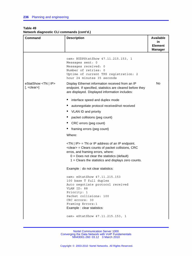
236 Planning and engineering
Table 49Network diagnostic CLI commands (cont’d.)
Command Description Availablein
ElementManager
oam> RUDPStatShow 47.11.215.153, 1Messages sent: 0Messages received: 0Number of retries: 0Uptime of current TPS registration: 2hour 24 minutes 35 seconds
eStatShow <TN | IP>[, <clear>]
Display Ethernet information received from an IPendpoint. If specified, statistics are cleared before theyare displayed. Displayed information includes:
• interface speed and duplex mode
• autonegotiate protocol received/not received
• VLAN ID and priority
• packet collisions (peg count)
• CRC errors (peg count)
• framing errors (peg count)
Where:
<TN | IP> = TN or IP address of an IP endpoint.<clear> = Clears counts of packet collisions, CRCerros, and framing errors, where:
0 = Does not clear the statistics (default)1 = Clears the statistics and displays zero counts.
Example : do not clear statistics:
oam> eStatShow 47.11.215.153100 base T full duplexAuto negotiate protocol receivedVLAN ID: 88Priority: 1Packet collisions: 100CRC errors: 30Framing Errors:1Example : clear statistics:
oam> eStatShow 47.11.215.153, 1
No
Nortel Communication Server 1000Converging the Data Network with VoIP Fundamentals
NN43001-260 03.12 3 March 2010
Copyright © 2003-2010 Nortel Networks. All Rights Reserved.
.

The VoIP network operation 237
Table 49Network diagnostic CLI commands (cont’d.)
Command Description Availablein
ElementManager
100 base T full duplexAuto negotiate protocol receivedVLAN ID: 88Priority: 1Packet collisions: 0CRC errors: 0Framing Errors: 0
isetInfoShow <TN | IP> Display standard DHCP configuration information, setfirmware version, hardware identification, and serverinformation of an IP Phone. Where:
<TN | IP> = TN or IP address of the IP Phone.
Example:
oam> isetInfoShow 47.11.215.153FW Version: 0602B50HWID: 18006038DD1ADB6600MAC: 006038DD1ADBVLAN ID: 124Priority: 6Set IP: 47.103.225.125Subnet Mask: 255.255.255.0Set Gateway: 47.103.225.1LTPS IP: 47.103.247.224Node IP: 47.103.247.224Node ID: 4420S1 Node IP: 47.103.247.229Port: 4100Action: 1S2 Node IP: 47.103.247.229Port: 4100Action: 1S5 Node IP: 47.103.247.229Port: 4100XAS: Net6
Yes
Nortel Communication Server 1000Converging the Data Network with VoIP Fundamentals
NN43001-260 03.12 3 March 2010
Copyright © 2003-2010 Nortel Networks. All Rights Reserved.
.

238 Planning and engineering
Table 49Network diagnostic CLI commands (cont’d.)
Command Description Availablein
ElementManager
RTPStatShow <TN | IP> Display QoS polling information. Where:
<TN | IP> = TN or IP address of the IP Phone.
Example:
The output lines in this example are truncated to fitin the available space; each line of output is actuallyprefixed by the following:
RTPStatShow Report (RTCP:XR) from Set(164.164.8.20)
oam> RTPStatShow 164.164.8.20Far End IP address: 164.164.8.21Far End Port: 5200Local Packet Sent: 2978Local Packet Received: 2535Local Packet Received out of order: 0Local Pkt Loss: 14%Local Average Jitter: 0msLocal Latency: 9msLocal Listening R: 63Vocoder Type: 0Local Avg Net Loss Rate: 14.79%Local Avg Discard Rate: 0.00%Local Avg Burst Density: 17.11%Local Avg Burst Length: 2070msLocal Gap Density: 10.34%Local Gap Length: 1080msLocal Avg End System Delay: 15msLocal Avg Noise Level: 0dBmLocal Avg Signal Power: 0dBmLocal Round Trip Time Avg: 19msLocal Round Trip Time Avg High: 19msRemote Listening R: 0Remote Avg Net Loss Rate: 0%Remote Avg Discard Rate: 0%Remote Avg Burst Density: 0%Remote Avg Burst Length: 0msRemote Gap Density: 0%Remote Gap Length: 0msRemote Avg End System Delay: 0msRemote Avg Noise Level: 0dBm
Yes
Nortel Communication Server 1000Converging the Data Network with VoIP Fundamentals
NN43001-260 03.12 3 March 2010
Copyright © 2003-2010 Nortel Networks. All Rights Reserved.
.

The VoIP network operation 239
Table 49Network diagnostic CLI commands (cont’d.)
Command Description Availablein
ElementManager
Remote Avg Signal Power: 0dBmRemote Round Trip Time Avg: 0msRemote Round Trip Time Avg High: 0msRemote Packet Loss: 0%Remote Average Jitter: 0msRemote Latency: 0ms
RTPTraceShow <TN | IP>[, <polling period>]
Display RTP/RTCP statistics for an IP endpoint. Thiscommand can be active across all calls. Where:
• <TN IP> = TN or IP address of the endpoint (tcid ifthe endpoint is a Voice Gateway Media Card)
• <polling period> = Number of polling periods tobe displayed. If not specified, default is 10 pollingperiods.
Example:
The output lines in this example are truncated to fitin the available space; each line of output is actuallyprefixed by the following:
RTPTraceShow Report from Set (164.164.8.20)
oam> RTPTraceShow 164.164.8.20Far End IP address: 164.164.8.21Far End Port: 5200Far End IP address: 164.164.8.21Far End Port: 5200Local Packet Sent: 2978Local Packet Received: 2535Local Packet Received out of order: 0Local Pkt Loss: 14%Local Average Jitter: 0msLocal Latency: 9msLocal Listening R: 63Vocoder Type: 0Local Avg Net Loss Rate: 14.79%Local Avg Discard Rate: 0.00%Local Avg Burst Density: 17.11%Local Avg Burst Length: 2070msLocal Gap Density: 10.34%Local Gap Length: 1080msLocal Avg End System Delay: 15msLocal Avg Noise Level: 0dBm
No
Nortel Communication Server 1000Converging the Data Network with VoIP Fundamentals
NN43001-260 03.12 3 March 2010
Copyright © 2003-2010 Nortel Networks. All Rights Reserved.
.

240 Planning and engineering
Table 49Network diagnostic CLI commands (cont’d.)
Command Description Availablein
ElementManager
Local Avg Signal Power: 0dBmLocal Round Trip Time Avg: 19msLocal Round Trip Time Avg High: 19msRemote Listening R: 0Remote Avg Net Loss Rate: 0%Remote Avg Discard Rate: 0%Remote Avg Burst Density: 0%Remote Avg Burst Length: 0msRemote Gap Density: 0%Remote Gap Length: 0msRemote Avg End System Delay: 0msRemote Avg Noise Level: 0dBmRemote Avg Signal Power: 0dBmRemote Round Trip Time Avg: 0msRemote Round Trip Time Avg High: 0msRemote Packet Loss: 0%Remote Average Jitter: 0ms RemoteLatency: 0ms
RTPTraceStop Request issuing IP endpoint to stop RTPTraceShow. No
For information about network diagnostic utilities, see IP PhonesFundamentals (NN43001-368) () and Signaling Server IP Line ApplicationsFundamentals (NN43001-125). .
Voice quality monitoringThe PVQM feature monitors voice quality by measuring the following:
• Latency : length of time for information to travel through the network,in seconds
• Jitter : variability in latency, in seconds
• Packet Loss : number of packets lost during transmission, inpercentage
• R:Value : measurement of listening R:Value using ITU E:Model.R:Value maps to Mean Opinion Score (MOS).
The sampled metrics are compared to user:configured thresholds todetermine system performance. When sampled metrics exceed configuredthresholds, statistics are generated on the system.
For details about configuring metric thresholds, see “Configure voicequality metric thresholds” (page 243).
Nortel Communication Server 1000Converging the Data Network with VoIP Fundamentals
NN43001-260 03.12 3 March 2010
Copyright © 2003-2010 Nortel Networks. All Rights Reserved.
.

The VoIP network operation 241
Statistics for each metric are collected on the Signaling Server or VoiceGateway Media Card to create a traffic report. The traffic report classifiesmetric threshold violation peg counts as Warning or Unacceptable.
Each summarized traffic report is added to the IP Phone zone TrafficReport 16 (TFS016), which in turn summarizes voice quality over thereporting period on a zone:by:zone basis. IP Phone zone Traffic Report 16(TFS016) provides the system administrator with an overall view of voicequality on the system. For information about IP Phone zone Traffic Report16 (TFS016), see Traffic Measurement Formats and Output Reference(NN43001-750) ().
An SNMP alarm is generated when a voice quality metric thresholdexceeds Warning or Unacceptable status. For details about controlling thenumber of SNMP alarms generated, see “Configure and print zone alarmnotification levels” (page 243).
IP Phones voice quality monitoringThe following diagram shows voice quality monitoring for IP Phones withinthe VoIP system.
Figure 52IP Phones voice quality monitoring
The following actions occur when you monitor voice quality for IP Phones:
Nortel Communication Server 1000Converging the Data Network with VoIP Fundamentals
NN43001-260 03.12 3 March 2010
Copyright © 2003-2010 Nortel Networks. All Rights Reserved.
.

242 Planning and engineering
1. The Signaling Server sends preset threshold values to the IP Phone.
2. Statistics are collected and compared on the IP Phone.
3. When a threshold is exceeded, the IP Phone sends an alert to theSignaling Server or Voice Gateway Media Card, which generates aninitial SNMP alarm.
For voice quality metric alarms that reach the Unacceptable level, thepath (tracer) of the voice media is written to the log file on the SignalingServer or Voice Gateway Media Card for diagnostic purposes.
4. Call quality information and alarm alert is forwarded to the Call Server.
5. The Call Server generates a second SNMP alarm.
Voice quality alarmsTable 50 "Call Server alarms : Call:by:call" (page 242) identifies metrics,threshold levels, alarming severity, and QoS alarms.
Table 50Call Server alarms : Call:by:call
MetricThreshold
level Severity Alarms
Call Server alarms : Call:by:call
Latency, Jitter, Packet Loss, R:Value Warning Info QoS0001 : QoS0005(excluding QoS0004)
Latency, Jitter, Packet Loss, R:Value Unacceptable Minor QoS0007 : QoS0010
Call Server alarms : Aggregated by zone
Latency, Jitter, Packet Loss, R:Value Warning Minor QoS0012 : QoS0015
Latency, Jitter, Packet Loss, R:Value Unacceptable Critical QoS0017 : QoS0020
Signaling Server (LTPS) alarms
Latency, Jitter, Packet Loss, R:Value Warning Warning QoS0022, QoS0024,QoS0026, QoS0028
Latency, Jitter, Packet Loss, R:Value Unacceptable Minor QoS0030, QoS0032,QoS0034, QoS0036
Latency, Jitter, Packet Loss, R:Value Clear Clear QoS0023, QoS0027,QoS0029, QoS0031,QoS0033, QoS0035,QoS0037
For information about QoS alarms, see Software Input Output Reference— System Messages (NN43001-712) ().
Nortel Communication Server 1000Converging the Data Network with VoIP Fundamentals
NN43001-260 03.12 3 March 2010
Copyright © 2003-2010 Nortel Networks. All Rights Reserved.
.

The VoIP network operation 243
Configure voice quality metric thresholdsThe system administrator can configure and print voice quality metricthresholds on a per:call or zone basis. Use the following commands in LD117:
• CHG CQWTH — Change voice quality Warning thresholds on a per callbasis.
• CHG CQUTH — Change voice quality Unacceptable thresholds on a percall basis.
• CHG ZQWTH — Change voice quality Warning thresholds on a zonebasis.
• CHG ZQUTH — Change voice quality Unacceptable thresholds on azone basis.
• PRT QSTHS — Display all voice quality thresholds.
• PRT AQoS — Display QoS records for zones.
• PRT ZQoS — Display QoS records for zones.
For detailed information about the previous commands, see Software InputOutput — Maintenance (NN43001-711). ()
Configure voice quality sampling (polling)Use the CHG SQoS command in LD 117 to configure the sampling (polling)period, zone:alarm:rate collection window, and the minimum number ofsamples to collect during the window.
For detailed information about the previous commands, see Software InputOutput — Maintenance (NN43001-711) ().
Configure and print zone alarm notification levelsSystems that process a large number of calls potentially generate asignificant number of SNMP alarms. Controlling the number of alarmsby configuring zone alarm notification levels helps isolate voice qualityproblems and reduce network traffic.
Voice quality threshold alarms are examined for their severity relative tothe alarm notification level settings. If the voice quality threshold alarmseverity exceeds the configured notification level, it generates an SNMPalarm; otherwise, the alarm is suppressed.
Voice quality threshold alarm notification levels can be set on azone:by:zone basis so that some bandwidth zones can be monitored forall alarms and other zones will report only serious voice quality problems.Alarm notification levels are defined in Table 51 "Voice quality thresholdalarm notification levels" (page 244).
Nortel Communication Server 1000Converging the Data Network with VoIP Fundamentals
NN43001-260 03.12 3 March 2010
Copyright © 2003-2010 Nortel Networks. All Rights Reserved.
.

244 Planning and engineering
Table 51Voice quality threshold alarm notification levels
Level Description Alarms
0 All voice quality alarms are suppressed None
1 Allow zone:based Unacceptable alarms QoS0017, QoS0018, QoS0019,QoS0020
2 Allow all of the above PLUS zone:basedWarning alarms
All of the above PLUS,QoS0012,QoS0013, QoS0014, QoS0015
3 Allow all of the above PLUS per:callUnacceptable alarms
All of the above PLUS,QoS0007,QoS0008, QoS0009, QoS0010,QoS0030, QoS0031, QoS0032,QoS0033, QoS0034, QoS0035,QoS0036, QoS0037
4 Allow all of the above PLUS per:call Warningalarms
All of the above PLUS,QoS0001,QoS0002, QoS0003, QoS0005,QoS0018, QoS0019, QoS0022,QoS0023, QoS0024, QoS0025,QoS0026, QoS0027,QoS0028, QoS0029
QoS0036 and QoS0037 are not currently reported.
The system administrator controls the number of alarms generated bythe system using the CHG ZQNL alarm notification level configurationcommands. The system administrator can print alarm notification levelsusing the PRT ZQNL command. Both commands are in LD 117.
For detailed information about these commands, see Software InputOutput — Maintenance (NN43001-711) ().
Heterogeneous environmentsIn an environment with a mixture of Nortel equipment and third:partyequipment, voice:quality monitoring, detection, and alarming is performedonly on IP endpoints that have voice quality monitoring capabilities.
For information on IP endpoints and their voice quality capabilities in thesystem, see Table 52 "IP endpoint and voice quality capabilities" (page245).
Nortel Communication Server 1000Converging the Data Network with VoIP Fundamentals
NN43001-260 03.12 3 March 2010
Copyright © 2003-2010 Nortel Networks. All Rights Reserved.
.

The VoIP network operation 245
Table 52IP endpoint and voice quality capabilities
Endpoint type Voice quality monitoring operation
IP Phones without PVQM package 401 Detects jitter, packet loss, and latency (whenthe far end is RTCP:compliant) thresholdviolations.
Threshold violations are detected asynchronously by the IP Phone.
IP Phones with PVQM package 401 Detects jitter, packet loss, and latency (whenthe far end is RTCP:compliant) and R:Valuethreshold violations.
Threshold violations are detected asynchronously by the IP Phone.
IP Softphone 2050 Detects jitter, packet loss, and latency (whenthe far end is RTCP:compliant) thresholdviolations.
Threshold violations are detected by polling.
Communication Server 1000 and Meridian1 systems with Voice Gateway Media Cardsrunning IP Line 4.0 (and later)
Detects jitter and packet loss thresholdviolations.
Threshold violations are detected by polling.
Third:party Gateway Not supported
Network ManagementSNMP Network Management SystemsSimple Network Management Protocol (SNMP):based NetworkManagement Systems (NMS) monitor Real:Time networks fromend:to:end. NMS ensures that problems on a network running Real:Timetraffic are solved quickly to maintain high:quality service.
SNMP NMS software can be configured to perform the following actions:
• map the network
• monitor network operation through polling of network devices
• centralize alarm management through SNMP traps
• notify network administrators of problems
The CS 1000 system can integrate into an NMS to provide a completeview of the converged voice and data network. Problems can be isolatedquickly when looking at the entire network.
Nortel Communication Server 1000Converging the Data Network with VoIP Fundamentals
NN43001-260 03.12 3 March 2010
Copyright © 2003-2010 Nortel Networks. All Rights Reserved.
.

246 Planning and engineering
SNMP Agent support is provided in TM. This allows alarms sent fromdevices to forward to the NMS.
Nortel also provides a complete line of Enterprise Network managementsoftware with the Enterprise Network Management Solutions product line.An SNMP interface is available in the traffic reporting system so that TM,or any third:party system, can have a standards:based interface into thesystem traffic reports. For more information, see Communication Server1000 Fault Management — SNMP (NN43001-719).
TM and Network Management SystemTM can be combined with Enterprise Network Management System(ENMS) Release 9.01, and later to provide an integrated data, voice,and video network, as part of a Unified Networking system. The result isintegrated LAN, WAN, and voice network management.
ENMS is an Enterprise:level network management solution, that providesfault, performance, configuration, and security management for Nortelinternetworking devices. ENMS enables network administrators to monitorand manage the network through a single view, and access any ENMSserver in the network from one client installation. It provides system:levelmanagement instead of managing one device at a time. ENMS providesgraphical views from physical connections between the LANs and WANsto the logical connections of a VLAN.
For more information about security management, see SecurityManagement (NN43001-604) ()
TM server activity can be monitored through ENMS.
TM Alarm Manager receives Simple Network Management Protocol(SNMP) traps from managed elements. Through Alarm Notification, TMsends filtered traps to ENMS.
Policy ManagementPolicy Management simplifies network QoS configuration by managingnetwork QoS policies from a central location.
Details, such as Layer 2, Layer 3, Layer 4, and trust configurations can beimplemented for the entire network from a central location. A variety ofpolicy managers are usually available from the network equipment vendor.
The Common Open Policy Services (COPS) protocol is used to transmitstandard policies to the network devices.
For more details on Nortel ENMS Policy Services, contact your Nortelrepresentative.
Nortel Communication Server 1000Converging the Data Network with VoIP Fundamentals
NN43001-260 03.12 3 March 2010
Copyright © 2003-2010 Nortel Networks. All Rights Reserved.
.

The VoIP network operation 247
CS 1000 network inventory and configurationRecord the current CS 1000 design and log all additions, moves, andchanges that occur in the CS 1000 network. The following informationmust be recorded:
• CS 1000 site information
— location
— dialing plan
— IP addressing
• Provisioning of CS 1000 nodes
— number of cards and ports
• CS 1000 node and card parameters
— fallback threshold level
— codec image
— voice and fax payload
— voice and fax playout delay
— audio gain, echo canceller tail delay size, Silence Suppressionthreshold
— software version
Nortel Communication Server 1000Converging the Data Network with VoIP Fundamentals
NN43001-260 03.12 3 March 2010
Copyright © 2003-2010 Nortel Networks. All Rights Reserved.
.

248 Planning and engineering
Nortel Communication Server 1000Converging the Data Network with VoIP Fundamentals
NN43001-260 03.12 3 March 2010
Copyright © 2003-2010 Nortel Networks. All Rights Reserved.
.

249.
ConfigurationThis chapter contains information about configuring a converged data andvoice network.
Navigation• “Quality of Service” (page 250)
• “Bandwidth Management” (page 251)
• “Configuring Dialing Plan” (page 257)
• "Zone Based Dialing" (page 273)
• “Meridian Customer Defined Network Alternate Routing and VacantNumber Routing ” (page 276)
• “Codec configuration” (page 276)
• “Adaptive Network Bandwidth Management configuration” (page 281)
• “Provisioning for Tandem Bandwidth Management ” (page 282)
• “Bandwidth Management support for Network Wide Virtual Office”(page 287)
• “Alternative call routing for Network Bandwidth Management” (page291)
• “Zone configuration” (page 315)
• “SIP Line service” (page 353)
Nortel Communication Server 1000Converging the Data Network with VoIP Fundamentals
NN43001-260 03.12 3 March 2010
Copyright © 2003-2010 Nortel Networks. All Rights Reserved.
.

250 Configuration
Communications Server 1000 configuration for networkrequirements
You can configure Communication Server 1000, in Release 6.0, to meetvarying network requirements, with the following three basic configurations:
• A Small configuration, which is suitable for single system installationsand a single ELAN subnet interconnecting all of the CommunicationServer 1000 dependent elements.
• A Normal configuration, which is suitable for larger installations anddeploys multiple ELAN subnets or multiple Communication Server1000 systems within the same UCM Security Domain.
• A Managed Services configuration, which is suitable for installationswhere complete isolation between the ELAN or Signaling andManagement Network, and the various Enterprise Networks arerequired.
Small configurationThe Small configuration is intended for small systems which consistof a single Call Server with a single ELAN subnet linking all of theCommunication Server 1000 elements, including the UCM PrimarySecurity Server. Routing is not required between the ELAN subnet andthe TLAN/Enterprise Network. The characteristics of systems using thisconfiguration are:
Quality of ServiceProcedure 2Configuring QoS in Element Manager
Step Action
1 In the Element Manager navigation tree, click IP Telephony,Nodes: Servers, Media Cards, Configuration.
The Node Configuration window appears.
2 In the Node Configuration window, click Edit next to the nodeto configure.
The Edit window appears.
Nortel Communication Server 1000Converging the Data Network with VoIP Fundamentals
NN43001-260 03.12 3 March 2010
Copyright © 2003-2010 Nortel Networks. All Rights Reserved.
.

Bandwidth Management 251
Figure 53QoS in Element Manager
3 Click QoS.
4 From the Input Value section, the following values must be set:Select Diffserv Codepoint(DSCP) Control packets= 40 : ClassSelector 5 (CS5). The range is 0 to 63. This configures thepriority of the signaling messaging.Select Diffserv Codepoint(DSCP) Voice packets = 46 :Control DSCP : Expedited Forwarding (EF). The range is 0 to 63.The Differentiated Service (DiffServ) CodePoint (DSCP)determines the priorities of the management and voice packetsin the IP Line network. The values are stored in IP telephonyCONFIG.INI file. The values used in the IP packets arerespectively 160 (40*4) and 184 (46*4).Click Enable 802.1Q support check box.Enter 802.1Q Bits value (802.1p) (Range 0 to 7).
5 Enter the IP Phone priority in the 802.1Q Bits value (802.1p)text box.
6 Click Save and Transfer.
--End--
Bandwidth ManagementThe following sections describe how to configure Bandwidth Managementin a Communication Server 1000 network.
Nortel Communication Server 1000Converging the Data Network with VoIP Fundamentals
NN43001-260 03.12 3 March 2010
Copyright © 2003-2010 Nortel Networks. All Rights Reserved.
.

252 Configuration
Configuration rulesThe following list contains the configuration rules for BandwidthManagement.
• Each Call Server in the network must be configured with a uniqueVPNI, with the exception that branch office (MG 1000B and SRG) CallServers must be configured with the same VPNI as that of the mainoffice Call Server with which they register.
• Different networks usually use different VPNI numbers
• Nortel recommends that all endpoints on a Call Server (IP Phonesand Voice Gateway Media Cards) be configured with the same zonenumber.
• Virtual Trunks must be configured with a different zone number thanthe endpoints.
Bandwidth Management configurationPerform the following steps to configure Bandwidth Management on theCall Server.
Configuring Bandwidth Management
Step Action
1 Define a VPNI number in LD 15.
2 Configure the Bandwidth Management parameters for each zoneon the Call Server using either Element Manager or LD 117.
For more information about Adaptive Network BandwidthManagement configuration parameters and Configurationusing LD 117, see “Adaptive Network Bandwidth Managementconfiguration” (page 281).
3 Configure Call Server zones to use for endpoints (telephone andgateways).
For more information about zones, see “Zones” (page 24).
• Intrazone Preferred Strategy = Best Quality (BQ)
• Intrazone Bandwidth = default (1 000 000 kbit/s)
• Interzone Preferred Strategy = Best Bandwidth (BB)
• Interzone Bandwidth = maximum bandwidth usage allowedbetween peer Call Servers
4 Configure Call Server zones to use for Virtual Trunks.
• Intrazone Mandatory Strategy = Best Quality (BQ)
• Intrazone Bandwidth = default (1000000)
Nortel Communication Server 1000Converging the Data Network with VoIP Fundamentals
NN43001-260 03.12 3 March 2010
Copyright © 2003-2010 Nortel Networks. All Rights Reserved.
.

Bandwidth Management 253
• Interzone Mandatory Strategy = Best Quality (BQ)
• Interzone Bandwidth = default (1000000)
5 Configure the IP Phone, DSP, and Virtual Trunk data with thecorresponding zone numbers.
For example, an IP Phone 2004 telephone in zone 8LD 11REQ NEWTYPE 2004P1, 2004P2...ZONE 8
--End--
For more information regarding Media Gateway channel zoneconfiguration, see Communication Server 1000E Installation andCommissioning (N43041:310). For more information on configuringtrunk zones, seeIP Peer Networking Installation and Commissioning(NN43001:313).
Maintenance commandsMaintenance commands can be run in Element Manager or LD 117.The prt intrazone and prt interzone commands are available in ElementManager from the Zones page.
Printing intrazone and interzone statistics for a zone
Step Action
1 In the Element Manager navigation tree, select IP Networks,Zones.The Zones window appears.
2 Click Maintenance Commands for Zones (LD 117).The Maintenance Commands for Zones pane opens, which liststhe configured zones.
Nortel Communication Server 1000Converging the Data Network with VoIP Fundamentals
NN43001-260 03.12 3 March 2010
Copyright © 2003-2010 Nortel Networks. All Rights Reserved.
.

254 Configuration
Figure 54Configured Zones list
3 Perform one of the following:
• To display intrazone statistics:
a. Select Print Interzone Statistics (PRT INTERZONE)from the Action list.
b. Select a zone from the Zone Number list, by doing of thefollowing:
– Select ALL to print statistics for all zones.
– Select a specific zone number to display statistics fora specific zone.
• To display interzone statistics:
— Select Print Intrazone Statistics per Local Zone (PRTINTRAZONE) from the Action list.
— Select a specific zone number to display statistics for aspecific zone.
4 Click Submit.
The Maintenance Commands for Zones pane appears, whichdisplays the statistics for the specified zone or zones. A blankfield indicates the statistic is either not available or not applicableto that zone.
Nortel Communication Server 1000Converging the Data Network with VoIP Fundamentals
NN43001-260 03.12 3 March 2010
Copyright © 2003-2010 Nortel Networks. All Rights Reserved.
.
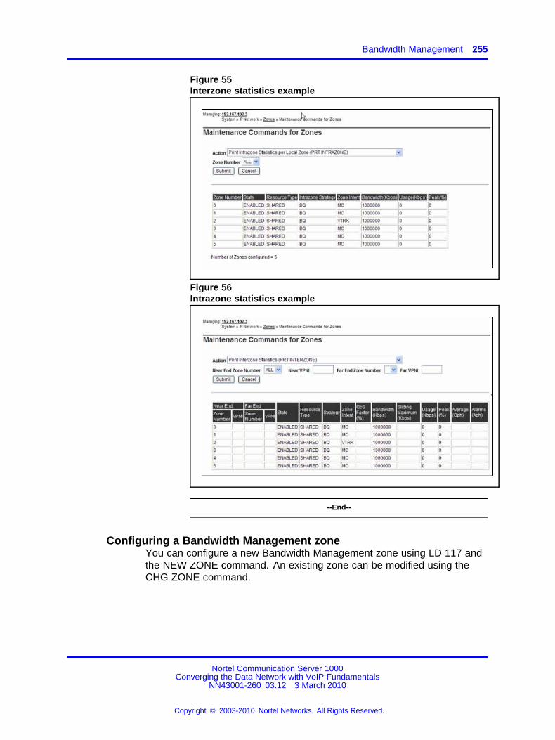
Bandwidth Management 255
Figure 55Interzone statistics example
Figure 56Intrazone statistics example
--End--
Configuring a Bandwidth Management zoneYou can configure a new Bandwidth Management zone using LD 117 andthe NEW ZONE command. An existing zone can be modified using theCHG ZONE command.
Nortel Communication Server 1000Converging the Data Network with VoIP Fundamentals
NN43001-260 03.12 3 March 2010
Copyright © 2003-2010 Nortel Networks. All Rights Reserved.
.

256 Configuration
Table 53LD 117 – Configure Bandwidth Management zone
Command Description
NEW | CHG ZONE <zoneNumber>[<intraZoneBandwidth><intraZoneStrategy>interZoneBandwidth><interZoneStrategy><zoneIntent><zoneResourceType>]
Configure a new zone (NEW) or change (CHG) an existingzone, where:• zoneNumber = 0:255
• intraZoneBandwidth = Available intrazone bandwidth(Kbit/s); Nortel recommends this value be set to themaximum value.
• intraZoneStrategy = BQ (Best Quality) or BB (BestBandwidth); Nortel recommends this value be set to BQ.
• interZoneBandwidth =
— For Call Server zone = Maximum bandwidth usage(in Kbit/s) allowed between peer Call Servers
— For Virtual Trunk zones = 1000000 (Kbit/s)
• interZoneStrategy = BQ (Best Quality) or BB (BestBandwidth); Nortel recommends this value be set to BBto conserve interzone bandwidth.
• zoneIntent = type of zone, where:
— MO = Main Office (Call Server) zone
— BMG = Branch Media Gateway (for branch officezones)
— VTRK = Virtual Trunk zone
• zoneResourceType = resource intrazone preferredstrategy, where:
— shared = shared DSP channels (default)
— private = private DSP channels
For more information about Private/Shared Zoneconfiguration, seeSignaling Server IP Line ApplicationsFundamentals (NN43001-125)
In Communication Server 1000 Release 5.5, the zones thatwere described with BMG designator stay with BMG one,all the other zones are provided with MO designator. It ispossible to update ZoneIntent using CHG ZONE command.
OUT ZONE <zoneNumber> Remove a zone.
DIS ZONE <zoneNumber> Disable a zone. When a zone is disabled, no new calls areestablished inside, from, or toward this zone.
ENL ZONE <zoneNumber> Enable a zone.
Nortel Communication Server 1000Converging the Data Network with VoIP Fundamentals
NN43001-260 03.12 3 March 2010
Copyright © 2003-2010 Nortel Networks. All Rights Reserved.
.

Configuring Dialing Plan 257
ATTENTIONDo not use the PRT ZONE command. It has been replaced by the PRTINTRAZONE and PRT INTERZONE commands.
Table 54LD 117 – Print zone statistics
Command Description
PRT INTRAZONE <zone> Print intrazone statistics for the identified zones, where:• zone = ALL or 0:255
The following output appears:• Zone
• Type = PRIVATE/SHARED
• Strategy = BB/BQ
• zoneIntent = MO/VTRK/BMG
• Bandwidth = number of Kbit/s
• Usage = number of Kbit/s
• Peak = %
PRT INTERZONE<nearZone><nearVPN><farZone><farVPN>
Print interzone statistics for the specific VPNI zone; where:• nearZone = ALL or 0:255
The folowing output appears:• Zone number = 0:255
• Zone VPNI = 1:16283
• Type= PRIVATE/SHARED
• Strategy = BB/BQ
• ZoneIntent = MO/VTRK
Configuring Dialing PlanUse the following procedures to configure the dialing plan for the main andbranch offices and the NRS database. See “Prerequisites to configure thedialing plan” (page 107) before proceeding with configuration.
Configuring the main office
Step Action
1 Configure the ZACB property for the branch office zone.
Nortel Communication Server 1000Converging the Data Network with VoIP Fundamentals
NN43001-260 03.12 3 March 2010
Copyright © 2003-2010 Nortel Networks. All Rights Reserved.
.

258 Configuration
Table 55LD 117 – Define the Zone Access Code for the branch office zone
Command Description
CHG ZACB <zone> [ALL] [<AC1|AC2><AC1|AC2>]
Define the Access Codes used to modify local orlong:distance calls in the branch office to force allbranch office calls to be routed to the MG 1000BPSTN.
The ZACB and ZDP properties are used to configure the digitmanipulation behavior of the branch office zone.
The ZACB property specifies which calls undergo digitmanipulation. The attribute can be configured in the followingways.
• CHG ZACB <zone>In this configuration, dialing AC1 or AC2 does not trigger digitmanipulation. SRG user calls are treated exactly the sameas those for main office users.
• CHG ACB <zone> ALLIn this configuration, calls dialed with AC1 and calls dialedwith AC2 undergo zone:based digit manipulation. All SRGuser calls can then be routed to the SRG PSTN.For example, assume that AC1 = 1, AC2 = 2, and ZDP =101. If an SRG user dials 1 87654321, ZDP is inserted in thedialed digits to form a digit string of 1 101 87654321. If anSRG user dials 2 87654321, ZDP is inserted in the dialeddigits to form a digit string of 2 101 87654321.
• CHG ZACB <zone> AC1 AC2In this configuration, only calls dialed with AC1 undergozone:based digit manipulation. All SRG user calls dialed withAC1 can then be routed to the SRG PSTN.For example, assume that AC1 = 1, AC2 = 2, and ZDP =101. If an SRG user dials 1 87654321, ZDP is inserted in thedialed digits to form a digit string of 2 101 87654321. If anSRG user dials 2 87654321, zone:based digit manipulationdoes not occur and the digit string remains unchanged.
• CHG ZACB <zone> AC2 AC2In this configuration, only calls dialed with AC2 undergozone:based digit manipulation. All SRG user calls dialed withAC2 can then be routed to the SRG PSTN.For example, assume that AC1 = 1, AC2 = 2, and ZDP =101. If an SRG user dials 1 87654321, zone:based digitmanipulation does not occur and the digit string remainsunchanged. If an SRG user dials 2 87654321, ZDP isinserted in the dialed digits to form a digit string of 2 10187654321.
Nortel Communication Server 1000Converging the Data Network with VoIP Fundamentals
NN43001-260 03.12 3 March 2010
Copyright © 2003-2010 Nortel Networks. All Rights Reserved.
.
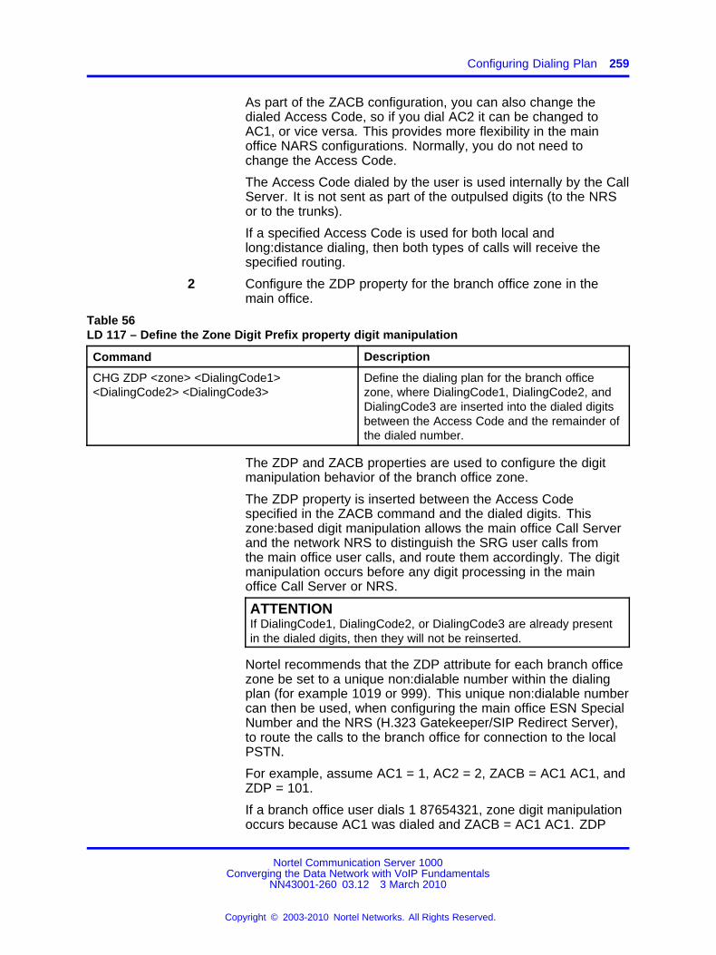
Configuring Dialing Plan 259
As part of the ZACB configuration, you can also change thedialed Access Code, so if you dial AC2 it can be changed toAC1, or vice versa. This provides more flexibility in the mainoffice NARS configurations. Normally, you do not need tochange the Access Code.
The Access Code dialed by the user is used internally by the CallServer. It is not sent as part of the outpulsed digits (to the NRSor to the trunks).
If a specified Access Code is used for both local andlong:distance dialing, then both types of calls will receive thespecified routing.
2 Configure the ZDP property for the branch office zone in themain office.
Table 56LD 117 – Define the Zone Digit Prefix property digit manipulation
Command Description
CHG ZDP <zone> <DialingCode1><DialingCode2> <DialingCode3>
Define the dialing plan for the branch officezone, where DialingCode1, DialingCode2, andDialingCode3 are inserted into the dialed digitsbetween the Access Code and the remainder ofthe dialed number.
The ZDP and ZACB properties are used to configure the digitmanipulation behavior of the branch office zone.
The ZDP property is inserted between the Access Codespecified in the ZACB command and the dialed digits. Thiszone:based digit manipulation allows the main office Call Serverand the network NRS to distinguish the SRG user calls fromthe main office user calls, and route them accordingly. The digitmanipulation occurs before any digit processing in the mainoffice Call Server or NRS.
ATTENTIONIf DialingCode1, DialingCode2, or DialingCode3 are already presentin the dialed digits, then they will not be reinserted.
Nortel recommends that the ZDP attribute for each branch officezone be set to a unique non:dialable number within the dialingplan (for example 1019 or 999). This unique non:dialable numbercan then be used, when configuring the main office ESN SpecialNumber and the NRS (H.323 Gatekeeper/SIP Redirect Server),to route the calls to the branch office for connection to the localPSTN.
For example, assume AC1 = 1, AC2 = 2, ZACB = AC1 AC1, andZDP = 101.
If a branch office user dials 1 87654321, zone digit manipulationoccurs because AC1 was dialed and ZACB = AC1 AC1. ZDP
Nortel Communication Server 1000Converging the Data Network with VoIP Fundamentals
NN43001-260 03.12 3 March 2010
Copyright © 2003-2010 Nortel Networks. All Rights Reserved.
.

260 Configuration
is inserted in the dialed digits to form a digit string of 1 10187654321. The call is routed differently than with the digits 187654321. ESN configuration at the main office Call Server(step 4) routes the call to the NRS because it recognizes 10187654321 after the Access Code rather than 87654321. TheAccess Code (1) is not included in the digit string that is sent tothe NRS. The NRS recognizes 101 at the front of the digit stringand routes the call to the destination SRG. At the branch office,the ESN Special Number is configured to remove 101 from thedigit string and route the call based on the digits 87654321.
If a branch office user dials 1 87654321, zone digit manipulationoccurs because AC1 was dialed and ZACB = AC1 AC1. ZDPis inserted in the dialed digits to form a digit string of 1 10187654321. The call is routed differently than with the digits 187654321. ESN configuration at the main office Call Serverroutes the call to the NRS because it recognizes 101 87654321after the Access Code rather than 87654321. The Access Code(1) is not included in the digit string that is sent to the NRS. TheNRS recognizes 101 at the front of the digit string and routesthe call to the destination SRG. At the branch office, the ESNSpecial Number is configured to remove 101 from the digit stringand route the call based on the digits 87654321.
If a branch office user dials 2 87654321, zone:based digitmanipulation does not occur because AC2 was dialed andZACB = AC1 AC1. The digit string remains unchanged 2101 87654321. The main office routes the call using ESNconfiguration and the dialed digits.
3 Configure the Route List Index at the main office.
After configuring zone:based digit manipulation, a specializedroute for the call must be configured. To select a trunk to routecalls, a Route List Index (RLI) must be configured in the RouteList Block (RLB). The RLI uses the route number for the VirtualTrunk to route calls to the NRS. A Digit Manipulation Index(DMI) is associated with the RLI to allow manipulation of thedigits to be outpulsed. For this application, at the main office,the DMI is used to update the call type of the off:net calls to theSpecial Number (SPN) to make sure the number stays in thePrivate/Special Number domain.
4 Configure the DMI in LD 86 with the DGT feature.
Table 57LD 86 – Configure the Digit Manipulation Index at the main office
Prompt Response Description
REQ NEW Add new data.
CUST xx Customer number as defined in LD 15.
FEAT DGT Digit manipulation data block
Nortel Communication Server 1000Converging the Data Network with VoIP Fundamentals
NN43001-260 03.12 3 March 2010
Copyright © 2003-2010 Nortel Networks. All Rights Reserved.
.

Configuring Dialing Plan 261
Prompt Response Description
DMI 1:999 Digit Manipulation Index numbersThe maximum number of Digit Manipulation tables isdefined at the MXDM prompt in LD 86.
DEL (0)::19 Number of leading digits to be deleted, usually 0 at themain office.
INST x...x Insert. Up to 31 leading digits can the main office.Default is none.
ISPN(YES)NO
IP Special NumberFor off:net callsFor on:net calls
CTYP
SPNLOC
Call type to be used by the call. This call type mustbe recognized by the NRS and far:end switch. This iscritical for correct CLID behavior.If ISPN=NO, the CLID is based on this field. IfISPN=YES, the CLID is based on the call type beforedigit manipulation.For off:net calls (ISPN=YES)For on:net calls (ISPN=NO)
5 Configure the RLI in LD 86 with the RLB feature.
Table 58LD 86 – Configure the Route List Index
Prompt Response Description
REQ NEW Add new data.
CUST xx Customer number as defined in LD 15.
FEAT RLB Route List data block
RLI0:1270:2550:999
Route List Index to be accessedCDP and BARSNARSFNP
ENTR 0:63X
Entry number for NARS/BARS Route ListPrecede with x to remove
LTER NO Local Termination entry
ROUT
0:5110:127
Route number of the Virtual Trunk as provisioned in LD 16.Range for Large SystemsRange for MG 1000B
...
DMI 1:999 Digit Manipulation Index number as defined in LD 86, FEAT= DGT
Nortel Communication Server 1000Converging the Data Network with VoIP Fundamentals
NN43001-260 03.12 3 March 2010
Copyright © 2003-2010 Nortel Networks. All Rights Reserved.
.
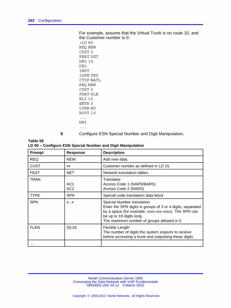
262 Configuration
For example, assume that the Virtual Trunk is on route 10, andthe Customer number is 0:>LD 86REQ NEWCUST 0FEAT DGTDMI 10DELINSTISPN YESCTYP NATLREQ NEWCUST 0FEAT RLBRLI 10ENTR 0LTER NOROUT 10...DMI...
6 Configure ESN Special Number and Digit Manipulation.
Table 59LD 90 – Configure ESN Special Number and Digit Manipulation
Prompt Response Description
REQ NEW Add new data.
CUST xx Customer number as defined in LD 15.
FEAT NET Network translation tables
TRANAC1AC2
TranslatorAccess Code 1 (NARS/BARS)Access Code 2 (NARS)
TYPE SPN Special code translation data block
SPN x...x Special Number translationEnter the SPN digits in groups of 3 or 4 digits, separatedby a space (for example, xxxx xxx xxxx). The SPN canbe up to 19 digits long.The maximum number of groups allowed is 5.
FLEN (0):24 Flexible LengthThe number of digits the system expects to receivebefore accessing a trunk and outpulsing these digits.
...
Nortel Communication Server 1000Converging the Data Network with VoIP Fundamentals
NN43001-260 03.12 3 March 2010
Copyright © 2003-2010 Nortel Networks. All Rights Reserved.
.

Configuring Dialing Plan 263
Prompt Response Description
: RLI 0:999 Route List Index configured in LD 86
: CLTP
LOCLNATLINTL
Type of call that is defined by the special number.Local PSTNNational PSTNInternational PSTN
--End--
After configuring the zone:based digit manipulation and specialized route,the route must be associated with the ESN Special Number. The mainoffice ESN Special Number configuration is based on new digits insertedby zone:based digit manipulation. The digits are processed based on theAccess Code, AC1 or AC2, that was dialed.
For off:net calls the following should be considered.
• If all calls that have undergone zone:based digit manipulation are to berouted by the NRS, one SPN must be provisioned for each call type toroute calls to the NRS based on the ZDP.
• If some calls are to be routed by the NRS, and others by the mainoffice Call Server, multiple SPN should be provisioned to route callsbased on the ZDP value and one or more dialed digits. Each SPN canthen use a different RLI if required.
For example, assume ZDP = 101. It is possible to provision multipleSPN (1011, 1012, 1013, 1014, 1015, 1016, 1017, 1018, 1019, and1010) to route calls based on the ZDP value plus the first dialed digit.However, it may not be necessary to provision all SPN combinations.For example, if calls dialed with a first digit of 3 after the Access Codeare invalid, then SPN 1013 does not need to be provisioned.
• Be careful when choosing how many dialed digits to include in theSPN. If one of the dialed digits is included in the SPN (that is, ZDP +one dialed digit), a maximum of ten SPN must be configured for eachbranch office. Similarly if two dialed digits are included in the SPN(ZDP + two dialed digits), a maximum of 100 SPN must be configuredfor each branch office. For each additional dialed digit included in theSPN, the maximum number of SPN that must be provisioned for eachbranch office is increased by a factor of ten.
If a single Access Code that undergoes zone:based digit manipulation isused for both on:net and off:net calls, then separate DMI and SPN must beprovisioned to correctly route these calls. The SPN must correctly identify
Nortel Communication Server 1000Converging the Data Network with VoIP Fundamentals
NN43001-260 03.12 3 March 2010
Copyright © 2003-2010 Nortel Networks. All Rights Reserved.
.
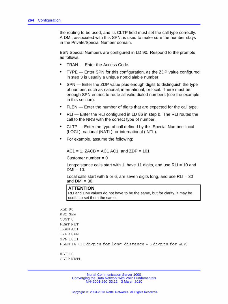
264 Configuration
the routing to be used, and its CLTP field must set the call type correctly.A DMI, associated with this SPN, is used to make sure the number staysin the Private/Special Number domain.
ESN Special Numbers are configured in LD 90. Respond to the promptsas follows.
• TRAN — Enter the Access Code.
• TYPE — Enter SPN for this configuration, as the ZDP value configuredin step 3 is usually a unique non:dialable number.
• SPN — Enter the ZDP value plus enough digits to distinguish the typeof number, such as national, international, or local. There must beenough SPN entries to route all valid dialed numbers (see the examplein this section).
• FLEN — Enter the number of digits that are expected for the call type.
• RLI — Enter the RLI configured in LD 86 in step b. The RLI routes thecall to the NRS with the correct type of number.
• CLTP — Enter the type of call defined by this Special Number: local(LOCL), national (NATL), or international (INTL).
• For example, assume the following:
AC1 = 1, ZACB = AC1 AC1, and ZDP = 101
Customer number = 0
Long:distance calls start with 1, have 11 digits, and use RLI = 10 andDMI = 10.
Local calls start with 5 or 6, are seven digits long, and use RLI = 30and DMI = 30.
ATTENTIONRLI and DMI values do not have to be the same, but for clarity, it may beuseful to set them the same.
>LD 90REQ NEWCUST 0FEAT NETTRAN AC1TYPE SPNSPN 1011FLEN 14 (11 digits for long:distance + 3 digits for ZDP)…RLI 10CLTP NATL
Nortel Communication Server 1000Converging the Data Network with VoIP Fundamentals
NN43001-260 03.12 3 March 2010
Copyright © 2003-2010 Nortel Networks. All Rights Reserved.
.

Configuring Dialing Plan 265
…SPN 1015FLEN 10 (7 digits for long:distance + 3 digits for ZDP)…RLI 30CLTP LOCL…SPN 1016FLEN 10 (7 digits for long:distance + 3 digits for ZDP)RLI 30CLTP LOCL...
After configuring main office routing to the NRS, the NRS database mustbe provisioned to identify the desired endpoint for the calls. This procedureconfigures the NRS database with the inserted digits specified by thezone:based digit manipulation configuration.
Instead of configuring the NRS database, you can configure a route in themain office to directly route the call.
Configuring the NRS database
Step Action
1 In NRS, click the Configuration tab.
2 Click set Standby DB view to work in the standby (inactive)database.
3 Select Routing entries from the navigation side of the NetworkRouting Service window.
The Routing Entries window appears.Figure 57NRS Routing Entries window
4 Choose the appropriate Service Domain, L1 Domain, and L0Domain from the corresponding drop:down menus.
Nortel Communication Server 1000Converging the Data Network with VoIP Fundamentals
NN43001-260 03.12 3 March 2010
Copyright © 2003-2010 Nortel Networks. All Rights Reserved.
.

266 Configuration
5 Click on Look up to open a window with a lookup path forgateway endpoints.
6 Click Search to display a list of gateway endpoints and click onthe endpoint at the branch office.
Figure 58NRS Look up path for gateway endpoints
A list of routing entries corresponding to that endpoint appears.Figure 59NRS Routing Entries window for selected endpoint
7 Click Add in the Routing Entries window to add a routing entry.
The Add Routing Entry window appears.
Nortel Communication Server 1000Converging the Data Network with VoIP Fundamentals
NN43001-260 03.12 3 March 2010
Copyright © 2003-2010 Nortel Networks. All Rights Reserved.
.

Configuring Dialing Plan 267
Figure 60Add Routing Entry
8 Configure the numbering plan entries for the branch office. Thisis usually set to the unique non:dialable number that identifiesthe branch office, as configured in the ZDP property of thebranch office zone in LD 117 at the main office.
The type of number configured in the NRS should be set tomatch the type of number as configured in the main office.
If some calls are to be routed differently from others, it ispossible to provision the multiple Numbering Plan Entries in theNRS to achieve this.
For example, if ZDP = 101, it is possible to provision multipleNumbering Plan Entries (101, 1011, and so on) to route callsbased on the ZDP value or the ZDP value plus some of thedialed digits.
Unlike on the Call Server, if the ZDP plus additional digits areused to identify routing it is not necessary to provision all of thecombinations. For example, if calls with digit strings starting with1011 are to be routed differently from those starting with 101x(where x is a digit other than 1), then only 101 and 1011 need tobe provisioned as numbering plan entries on the NRS.
--End--
Configuring the branch office
Step Action
1 Configure the Route List Index at the branch office.
After the call arrives at the branch office, a route must beprovisioned to handle the call. In order to be able to select atrunk to route calls, a Route List Index (RLI) must be configuredin the Route List Block (RLB). The RLI uses the route numberfor PSTN trunk to route calls to the PSTN. A Digit ManipulationIndex (DMI) can be associated with the RLI to allow manipulationof the digits to be outpulsed. For this application, the DMI is usedto remove the ZDP digits that were inserted in the dialed digits
Nortel Communication Server 1000Converging the Data Network with VoIP Fundamentals
NN43001-260 03.12 3 March 2010
Copyright © 2003-2010 Nortel Networks. All Rights Reserved.
.

268 Configuration
at the main office. The DMI is also used to convert the call typeback correctly according to the incoming SPN pattern.
2 Configure the DMI in LD 86 with the DGT feature.
Table 60LD 86 – Configure the Digit Manipulation Index at the branch office
Prompt Response Description
REQ NEW Add new data.
CUST xx Customer number as defined in LD 15
FEAT DGT Digit manipulation data block
DMI 1:999 Digit Manipulation index numbers
DEL (0):19 Number of leading digits to be deleted.This would normally be configured to remove the uniquenon:dialable number that identifies the branch office,configured in the ZDP property of the branch office zone inLD 117 at the main office.
ISPN NO IP Special Number
INST x...x
INTLNPANXXLOCSPN
Insert. UP to 32 leading digits can be inserted.Call type used by the call. The far:end switch must recognizethis call type.InternationalNationalUDPLocal PSTNSpecial Number
3 Configure the RLI in LD 86 with the RLB feature.
Table 61LD 86 – Configure Route List Index
Prompt Response Description
REQ NEW Add new data.
CUST xx Customer number as defined in LD 15.
FEAT RLB Route List data block
RLI0:1270:2550:999
Route List Index to be accessedCDP and BARSNARSFNP
ENTR 0:63X
Entry number for NARS/BARS Route ListPrecede with x to remove
LTER NO Local Termination entry
Nortel Communication Server 1000Converging the Data Network with VoIP Fundamentals
NN43001-260 03.12 3 March 2010
Copyright © 2003-2010 Nortel Networks. All Rights Reserved.
.

Configuring Dialing Plan 269
Prompt Response Description
ROUT
0:5110:127
Route number of the Virtual Trunk as provisioned in LD 16.Range for Large SystemsRange for MG 1000B
...
DMI 1:999 Digit Manipulation Index number as defined in LD 86, FEAT= DGT
For example, assume that the PSTN trunk is on route 18 and theCustomer number = 0.
>LD 86REQ NEWCUST 0FEAT DGTDMI 18DEL 3 (Set to remove ZDP added in the main office)INSTCTYP LOC (Set according to associated SPN pattern)REQ NEWCUST 0FEAT RLBRLI 18ENTR 0LTER NOROUT 18...DMI 18...
4 Configure ESN Special Number and Digit Manipulation.
Table 62LD 90 – Configure ESN Special Number and Digit Manipulation
Prompt Response Description
REQ NEW Add new data.
CUST xx Customer number as defined in LD 15.
FEAT NET Network translation tables
TRAN AC1 Translator – Access Code 1 (NARS/BARS)Because the call is incoming to the branch office, AC1is triggered if INAC = YES in the Route Data Block forthe Virtual Trunk in LD 16 and the INTL call type isassociated with AC1 in NET_DATA of the CustomerData Block in LD 15.
TYPE SPN Special code translation data block
Nortel Communication Server 1000Converging the Data Network with VoIP Fundamentals
NN43001-260 03.12 3 March 2010
Copyright © 2003-2010 Nortel Networks. All Rights Reserved.
.

270 Configuration
Prompt Response Description
x...x Special Number translationEnter the SPN digits in groups of 3 or 4 digits, separatedby a space (for example, xxxx xxx xxxx). The SPN canbe up to 19 digits long.The maximum number of groups allowed is 5.
: FLEN (0):24 Flexible LengthThe number of digits the system expects to receivebefore accessing a trunk and outpulsing these digits.
...
: RLI 0:999 Route List Index configured in LD 86
After configuring the specialized route for calls that have beenrouted to the branch office by the NRS, the route must beassociated with the ESN Special Number.
The branch office receives the manipulated number as anincoming call, indicating that the ZDP value added at the mainoffice is at the beginning of the number. The branch office ESNconfiguration must ensure that the extra digits (the ZDP value)are deleted by using a proper DMI. The call then terminates atthe PSTN connection.
ATTENTIONThe DMI configured in LD 86 in step 1 is used to remove the digitsthat were inserted in the dialed number at the main office.
For example, assume ZDP at the main office = 101, Customernumber = 0, and the RLI for the PSTN trunk = 18.
LD > 90REQ NEWCUST 0FEAT NETTRAN AC1TYPE SPNSPN 1011FLEN 0…RLI 18
--End--
Configuring the dialing plan using Communication Server 1000Element Manager
In Element Manager, configure the branch office–specific zone dialing planand access codes.
Nortel Communication Server 1000Converging the Data Network with VoIP Fundamentals
NN43001-260 03.12 3 March 2010
Copyright © 2003-2010 Nortel Networks. All Rights Reserved.
.

Configuring Dialing Plan 271
Configuring the branch office dialing plan and access codes
Step Action
1 In the Element Manager navigation tree, select IP Network,Zones.
The Zones window appears.Figure 61Zones window
2 In the Zones window in Element Manager, select the BranchOffice Dialing Plan and Access Codes option, and enter thenecessary information.
Nortel Communication Server 1000Converging the Data Network with VoIP Fundamentals
NN43001-260 03.12 3 March 2010
Copyright © 2003-2010 Nortel Networks. All Rights Reserved.
.

272 Configuration
Figure 62Zone dialing Plan and Access Codes
--End--
Testing PSTN access using an SRG or MG 1000B IP PhoneUse the following procedure to test that PSTN access is working correctly.
Testing PSTN access using an SRG or MG 1000B IP Phone
Step Action
1 From an SRG or MG 1000BIP Phone in Local Mode:
a Make a local PSTN call.
b Make a long:distance call.
The calls must be routed according to the branch office ESNconfiguration.
2 From an SRG or MG 1000B IP Phone in Normal Mode:
a Make a local PSTN call.
b Make a long:distance call.
The calls must be routed according to the main office ESNconfiguration.
--End--
Nortel Communication Server 1000Converging the Data Network with VoIP Fundamentals
NN43001-260 03.12 3 March 2010
Copyright © 2003-2010 Nortel Networks. All Rights Reserved.
.

Zone Based Dialing 273
TroubleshootingFor calls that tandem over the Virtual Trunk to the branch office and goout to the PSTN trunks in the branch office, the following configurationproblems can occur:
• The call receives overflow tones. Use LD 96 to view the digits sent tothe Virtual Trunk (ENL MSGO {dch#}).
• If the digits look correct at the main office, the NRS might not beproperly configured. If the NRS rejects the call, a diagnostic messageis displayed on the Signaling Server console.
• If the call makes it to the correct branch office (check that it is not goingto the wrong node if the NRS is configured incorrectly) the branchoffice is probably rejecting it because it does not know the digit string.Use LD 96 to view the digits (ENL MSGI {dch#}).
For more information about troubleshooting, see Branch Office Installationand Commissioning (NN43001-314) ().
Zone Based DialingTo configure zone based parameters, the Zone Based Dialing plan optionis activated using LD 15. After it is set to YES, the DIALPLAN prompt isshown to select public or private on:net dial plan.
Overlay 15A new prompt, DIALPLAN, is added to LD 15. If it set to PUB, thenappropriate E.164 CLID is displayed on a terminating set.
Table 63New prompts for Overlay 15
Prompt Response Comment
REQ: CHG Change the existing data block
TYPE: FTR_DATA Customer features and options
...
VO_CUR_ZONE_TD (NO) YES
ZBD (NO) YES ZBD option
: DIAL_PLAN PUB or PRV Type of dialing plan for DN and CLIDdisplaying
Configure the numbering zones for sets in LD 10, 11, and 12.
ATTENTIONYou can only assign numbering zones to a set when it is configured in Overlay117.
Nortel Communication Server 1000Converging the Data Network with VoIP Fundamentals
NN43001-260 03.12 3 March 2010
Copyright © 2003-2010 Nortel Networks. All Rights Reserved.
.

274 Configuration
In following examples, assume that two sites exist; Belleville with DirectInward Dialing (DID) numbers, 1 613 967 4xxx and Amsterdam, 31 20 6303xxx.
Configuring numbering zone and numbering zone based parametersThe following configuration tasks are for Overlay 117.
Table 64Configuration tasks for Overlay 117
Configuration task Command Input parameters Output
Add numbering zone NEW NUMZONE (numbering zone number : mandatory)(parameters list – optional)
none
Change numbering zoneparameters
CHG NUMZONE (numbering zone number : mandatory)(parameters list – mandatoryl)
none
Remove numberingzone
OUT NUMZONE (numbering zone number : mandatory) none
Printout numbering zoneparameters
PRT NUMZONE (numbering zone number – optional)(range : optional)
none
The following table displays a sample numbering zone printout.
Table 65Sample printout for the PRT NUMZONE command with sample values
Zone PREF CC NPA AC1 AC2 NATC INTC DAC TTBL FLAGS
0:1023 00:9999 0:9999 0:9999 0:99 0:99 0:9999
0:9999 (0):1 (0):32
(0x0):0xff
The following header descriptions, describe each of the header entries inTable 64, Sample...:
• PREF: site prefix
• CC: country code
• NPA: area code, used for dialing through ZFDP
• AC1: trunk access code 1
• AC2: trunk access code 2
• NATC: national dial code
• INTC: international dial code
• DAC: the flag to delete an NPA from CLID for a local subscriber call. Italso show you dial NPA for a NXX/REG2 call. If DAC is 0 thenAC + NPA + NXX + DN should be dialed. If DAC is 1 then AC + NXX +DN should be dialed.
Nortel Communication Server 1000Converging the Data Network with VoIP Fundamentals
NN43001-260 03.12 3 March 2010
Copyright © 2003-2010 Nortel Networks. All Rights Reserved.
.
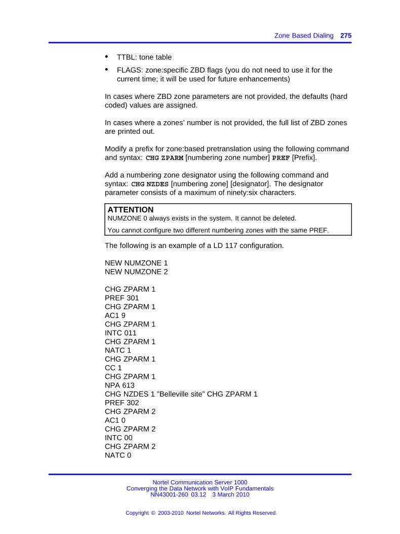
Zone Based Dialing 275
• TTBL: tone table
• FLAGS: zone:specific ZBD flags (you do not need to use it for thecurrent time; it will be used for future enhancements)
In cases where ZBD zone parameters are not provided, the defaults (hardcoded) values are assigned.
In cases where a zones’ number is not provided, the full list of ZBD zonesare printed out.
Modify a prefix for zone:based pretranslation using the following commandand syntax: CHG ZPARM [numbering zone number] PREF [Prefix].
Add a numbering zone designator using the following command andsyntax: CHG NZDES [numbering zone] [designator]. The designatorparameter consists of a maximum of ninety:six characters.
ATTENTIONNUMZONE 0 always exists in the system. It cannot be deleted.
You cannot configure two different numbering zones with the same PREF.
The following is an example of a LD 117 configuration.
NEW NUMZONE 1NEW NUMZONE 2
CHG ZPARM 1PREF 301CHG ZPARM 1AC1 9CHG ZPARM 1INTC 011CHG ZPARM 1NATC 1CHG ZPARM 1CC 1CHG ZPARM 1NPA 613CHG NZDES 1 ”Belleville site” CHG ZPARM 1PREF 302CHG ZPARM 2AC1 0CHG ZPARM 2INTC 00CHG ZPARM 2NATC 0
Nortel Communication Server 1000Converging the Data Network with VoIP Fundamentals
NN43001-260 03.12 3 March 2010
Copyright © 2003-2010 Nortel Networks. All Rights Reserved.
.

276 Configuration
CHG ZPARM 2CC 31CHG ZPARM 2NPA 20CHG NZDES 2 ”Amsterdam site”
Meridian Customer Defined Network Alternate Routing and VacantNumber Routing
Existing configurations for Meridian Customer Defined Network AlternateRouting (MALT) and Vacant Number Routing (VNR) are required for thefeature to work properly.
Meridian Customer Defined Network Alternate Routing configurationMALT is performed based on SBOC configurations done in the RLB forVNR RLI. If you configure SBOC to RRA, then Rerouting is accomplishedin the current node for all the MALT cause values. If you configure SBOCto RRO, then rerouting is accomplished at the originating node. If youconfigure SBOC to NRR, then MALT is not to be. Configure the MALTprompt with the number of alternate routes that are tried for the respectiveRLI. Configure SBOC on the last entry as a value other than RRA/RRO;make it NRR (no reroute).
Vacant Number Routing configurationVNR must be configured to yes in LD 15. NET_DATA and the RLIselected for VNR calls are given. The prerequisite for configuring VNR,FNP, must be set to yes. For more information on VNR configuration, seeIP Peer Networking Installation and Commissioning (NN43001-313).
Codec configurationThe following sections describes how to configure codecs and inCommunication Server 1000.
G.729 VAD negotiation via SIPWhen configuring the G.729 codec, the setting Voice Activity Detection(VAD), impacts largely on bandwidth usage.
Use G.729 Annex B for VAD. When SIP negotiations for media capabilityoccur, a device explicitly states Annex B capability, or it implies VADsupport by not stating support.
If you configure the IP Peer configuration as Communication Server1000 G.729 VAD = No, and configure the other Nortel or Third Party SIPdevice as G.729 VAD = Yes (or do not state Annex B capability in the SIPmessaging), a speech path issue could occur. To correct this, configurethe Communication Server 1000 G.729 VAD = Yes.
Nortel Communication Server 1000Converging the Data Network with VoIP Fundamentals
NN43001-260 03.12 3 March 2010
Copyright © 2003-2010 Nortel Networks. All Rights Reserved.
.

Codec configuration 277
Configuring codecsPerform the following steps to configure codecs.
Procedure 3Configuring codecs
Step Action
1 In the Element Manager navigation tree, select System, IPNetwork, Nodes: Servers, Media Cards .
The IP Telephony Nodes page appears.
2 In the IP Telephony Nodes page, click Edit for the appropriatenode.
Figure 63IP Telephony Nodes
The Edit window appears.
Nortel Communication Server 1000Converging the Data Network with VoIP Fundamentals
NN43001-260 03.12 3 March 2010
Copyright © 2003-2010 Nortel Networks. All Rights Reserved.
.

278 Configuration
Figure 64Edit window
3 Click VGW and IP phone codec profile to open the parameterlist.
This area also includes a list of codecs.
Nortel Communication Server 1000Converging the Data Network with VoIP Fundamentals
NN43001-260 03.12 3 March 2010
Copyright © 2003-2010 Nortel Networks. All Rights Reserved.
.
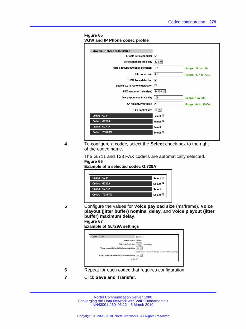
Codec configuration 279
Figure 65VGW and IP Phone codec profile
4 To configure a codec, select the Select check box to the rightof the codec name.
The G.711 and T38 FAX codecs are automatically selected.Figure 66Example of a selected codec G.729A
5 Configure the values for Voice payload size (ms/frame), Voiceplayout (jitter buffer) nominal delay, and Voice playout (jitterbuffer) maximum delay.Figure 67Example of G.729A settings
6 Repeat for each codec that requires configuration.
7 Click Save and Transfer.
Nortel Communication Server 1000Converging the Data Network with VoIP Fundamentals
NN43001-260 03.12 3 March 2010
Copyright © 2003-2010 Nortel Networks. All Rights Reserved.
.

280 Configuration
The system saves the changes and transfers the nodeconfiguration files to all elements in the node (Signaling Servers,Call Server, and Voice Gateway Media Cards).
A warning dialog box opens asking if you want to save andtransfer the configuration changes.Figure 68Save and Transfer dialog box
8 Click OK.
The following series of windows appear.
• Transfer Progress window
• Transfer Failure Report window (if applicable)
• Transfer/Status window.
The Transfer successful to all elements in the node windowsappears.
9 Click OK.
The Transfer/Status window appears.
10 Select one of the following:
• Select All
• Unselect All
• Transfer to Selected Elements
OR
11 Click Cancel to return to the Node Configuration window.
The Node Configuration window reappears.
Nortel Communication Server 1000Converging the Data Network with VoIP Fundamentals
NN43001-260 03.12 3 March 2010
Copyright © 2003-2010 Nortel Networks. All Rights Reserved.
.
Adaptive Network Bandwidth Management configuration 281
ATTENTIONThe Transfer/Status window is used to send the node configurationfiles to all IP Telephony components in the node. The followingoccurs if there is a error:
• If any element within the Node fails to transfer eitherBOOTP or CONFIG files, the Transfer/Status button ishighlighted in red.
• If the transfer status of the node elements is unavailable, theTransfer/Status button is highlighted in yellow .
--End--
Adaptive Network Bandwidth Management configurationThis section contains information on configuration rules and advancednotes for Adaptive Network Bandwidth Management. For information onconfiguring Adaptive Network Bandwidth Management, see “ConfiguringAdaptive Network Bandwidth Management and CAC” (page 317)
Configuration rulesThe following list contains the configuration rules for Adaptive NetworkBandwidth Management.
• Adaptive Bandwidth Management only applies to INTERZONE calls(not INTRAZONE calls).
• All branch offices (MG 1000B or SRG) associated with a particularmain office must have the same VPNI as the main office Call Server.
• All IP Phones (other than the IP Softphone 2050) and DSP endpointson a Call Server must be configured for the same zone.
• The IP Softphone 2050 used remotely must be configured for zone 0.
• Branch office systems (MG 1000B or SRG) should tandem all callsthrough the main office Call Server to allow bandwidth monitoring andcontrol. The media path is direct between the branch office and anypoint in the network.
• Trunk Route Optimization (TRO) must be disabled between the mainoffice Call Server and the MG 1000B Core or SRG. The media path isdirect between the branch office and any point in the network.
• Adaptive Network Bandwidth Management parameters are configuredon the main office only and must not be configured at the branchoffices.
Nortel Communication Server 1000Converging the Data Network with VoIP Fundamentals
NN43001-260 03.12 3 March 2010
Copyright © 2003-2010 Nortel Networks. All Rights Reserved.
.
282 Configuration
Advanced configuration notesThe following information describes advanced configuration for AdaptiveNetwork Bandwidth Management.
• The default values for Cpl, Cj, Cd, Cr, and CQos can be increased toincrease the response time for Sliding Maximum changes. However,increasing the default values can cause the Sliding Maximum totemporarily decrease to a lower value then necessary, resulting in theneedless blocking of interzone calls.
• Increasing the value of ZQRT will increase the speed at which theSliding Maximum increases. The same effect can be achieved bydecreasing ZQRTI. However, changing these values can cause thesliding maximum to oscillate until the network degradation is removed.
• To change the notification level (ZQNL) of the Call Server so it canreact to the QoS alarms, use LD 117 to change this level. For moreinformation about alarm notification levels, see “Configure and printzone alarm notification levels” (page 243).
Element Manager configurationElement Manager can be used to enable and configure the feature.
A zone must exist before it can be configured for Adaptive NetworkBandwidth Management. For more information about configuring AdaptiveNetwork Bandwidth Management and how to create and configure basicproperties of the zone, see “Adaptive Network Bandwidth Managementand CAC” (page 316).
Provisioning for Tandem Bandwidth ManagementThe following steps summarize how to provision for Tandem BandwidthManagement.
Nortel Communication Server 1000Converging the Data Network with VoIP Fundamentals
NN43001-260 03.12 3 March 2010
Copyright © 2003-2010 Nortel Networks. All Rights Reserved.
.

Provisioning for Tandem Bandwidth Management 283
Figure 69Network configuration provisioning example
Step Action
1 Enter the main office Gateway endpoint identifier in the TandemEndpoint field for each branch office gateway configured on theNRS.
This provides tandeming for outbound calls from a branch officethrough its main office.
Nortel Communication Server 1000Converging the Data Network with VoIP Fundamentals
NN43001-260 03.12 3 March 2010
Copyright © 2003-2010 Nortel Networks. All Rights Reserved.
.

284 Configuration
Figure 70Tandem endpoint configuration in Element Manager
2 Plan the gateway routing prefixes, if not already done. At leastone prefix is needed for each branch office. Any branch officethat has a prefix for ESN 911 calls does not require another.
These prefixes are SPN (Special Number) entries when usingESN 911.
3 Provision the NRS to send all calls to an LOC without a gatewayrouting prefix to the main office of that LOC or to the main officewhich provides service for the branch office using the LOC.
In the example, the NRS is provisioned with 841 (for main officeB) and 842 (for main office A).
4 Provision the NRS to send all calls to a LOC with a gatewayrouting prefix to the branch office directly.
Using the gateway routing prefix and the Type of Number ofSPN, the entries can be differentiated from the normal LOCseasily.
In the example, the NRS is provisioned with 741:841 at branchoffice B and 742:842 for branch office A.
5 Provision the main office with the DGT table DMIs to insert theprefixes and set the Type of Number correctly.
6 Create RLB RLI entries to use these DMIs for the VTRK routes.One RLI per branch office is the minimum requirement. Note thatcalls from remote systems typically have the HLOC prefix.
Nortel Communication Server 1000Converging the Data Network with VoIP Fundamentals
NN43001-260 03.12 3 March 2010
Copyright © 2003-2010 Nortel Networks. All Rights Reserved.
.

Provisioning for Tandem Bandwidth Management 285
Table 66Main office B DMI and RLI provisioning (for calls in branch office B)
Create a DMI Create an RLI
LD 86 LD 86
REQ new REQ new
CUST 0 CUST 0
FEAT dgt FEAT flb
DMI 50 RLI 50
DEL 0 ENTR 0
ISPN no LTER no
INST 741841 ROUT 71
CTYP loc DMI 50
7 Provision the main office with CDP DSCs (mapped by the RLIinto Location Codes) sufficient to uniquely identify all of itsbranch offices (using extended location codes, if required)
Use the RLI index defined for each branch office as the RLIvalue of the LOC definition. This is the route to the branch office.
Table 67Main office B LOC provisioning for LOC 741 841
Create a CDP mapped to the LOC:
LD 87
REQ new
CUST 0
FEAT CDP
TYPE DSC
DSC 4030
FLEN 4
RLI 50
Create a CDP mapped to the LOC:
LD 87
8 Provision the main office and branch office with a home locationcode (HLOC) or multiple codes to terminate all calls that shouldterminate on this system.
Table 68Main office and branch office HLOC provisioning : Main office B and branch office B
Create a DMI Create an HLOC
LD 86 LD 90
Nortel Communication Server 1000Converging the Data Network with VoIP Fundamentals
NN43001-260 03.12 3 March 2010
Copyright © 2003-2010 Nortel Networks. All Rights Reserved.
.

286 Configuration
Create a DMI Create an HLOC
REQ new REQ new
CUST 0 CUST 0
FEAT dgt FEAT net
DMI 61 TRAN ac1
DEL 3 TYPE hloc
ISPN no HLOC 841
DMI 61
9 Provision the main office to send all other LOCs to the IPnetwork without prefixes. These are going to a remote mainoffice.
Table 69Main office B LOC provisioning for LOC to remote main office system : main office A is LOC842
Create an RLI Create a LOC
LD 86 LD 90
REQ new REQ new
CUST 0 CUST 0
FEAT rlb FEAT net
RLI 51 TRAN ac1
ENTR 0 TYPE loc
LTER no LOC 842
ROUT 75 FLEN 7
RLI 71
10 Provision the branch office with a terminating RLI with a DMI todelete the LOC prefixes.
Table 70Branch office terminating RLI provisioning
Create a DMI Create an HLOC
LD 86 LD 90
REQ new REQ new
CUST 0 CUST 0
FEAT dgt FEAT net
DMI 61 TRAN ac1
DEL 6 TYPE hloc
Nortel Communication Server 1000Converging the Data Network with VoIP Fundamentals
NN43001-260 03.12 3 March 2010
Copyright © 2003-2010 Nortel Networks. All Rights Reserved.
.

Bandwidth Management support for Network Wide Virtual Office 287
Create a DMI Create an HLOC
ISPN no HLOC 741
DMI 61
--End--
Bandwidth Management support for Network Wide Virtual OfficeA Current Zone field is introduced for the IP phones to distinguishbetween the Bandwidth zone number configured for the IP phone andthe current nonconfigurable zone number, but is changed dynamicallyby Virtual Office feature operation. The Current Zone field is used in thebandwidth calculation routines instead of the Configured Zone field to havecorrect bandwidth calculation in case of Network Wide Virtual Office callscenarios.
The administrator can check the value of the Current Zone for IP phonesthat use the LD 20, PRT command. This value is not configurable so nochanges are made in LD 11.
PrerequisitesThe following configuration is used:
• Bandwidth zones are allocated on a Network-wide basis.
• All zones in the network are configured on all the Call Servers.
• All Call Servers within the network have the identical copy of the zonetable and each individual zone policy.
• Main Office and Branch Office need to have the same VPNI settingto ensure correct bandwidth management control by the Main Office.Also, they must have the same VPNI setting across call servers so asto support bandwidth management for Network Wide Virtual Office(NWVO). Two systems within the same LAN requires the same VPNIsetting to ensure INTRAZONE call treatment.
• Call Servers that belong to different networks have different VPNInumbers. Each network has its own individual VPNI numbers.
• Divide a network into several VPNIs if it consists of more than 255locations. Use a zone number between 1 to 255 because zone 0does not support Alternative Call Routing and Adaptive BandwidthManagement.
• The identical copy of the zone table within the network shouldbe configured manually unless a synchronization mechanism isintroduced.
Nortel Communication Server 1000Converging the Data Network with VoIP Fundamentals
NN43001-260 03.12 3 March 2010
Copyright © 2003-2010 Nortel Networks. All Rights Reserved.
.

288 Configuration
Operating parametersThe following list describes the operating parameters to support a NetworkWide Virtual Office.
• Only IP Phones with the IP Client cookies feature enabled aresupported
• The correct Bandwidth Management calculation for a Virtual Office(VO) IP Phone is possible only within the home customer network(when all the systems are configured with the same VPNI number).
• The maximum number of Bandwidth Zones that can be configured onthe Call Servers within the home customer network is limited to 255(1 to 255).
• Interaction with previous releases is not supported. Therefore, thecorrect bandwidth calculation is not provided if a remote VO login isperformed from a Communication Server 1000 with a software releasethat is earlier than Communication Server 1000 Release 5.0. In thiscase, the earlier release bandwidth calculation method is used.
• If two or more Call Servers have the same VPNI and Bandwidth zoneconfigured, the usage in this zone can not be synchronized betweenthese Call Servers.
• The feature supports only one customer. If more than one customeris configured, the customer with the lowest customer number issupported.
Feature PackagingThe Bandwidth Management support for Network Wide Virtual Officefeature requires the following two packages on the system:
• Virtual Office (VO) package 382
• Virtual Office Enhancement (VOE) package 387
Feature ImplementationUse the following tables to implement this feature.
Table 71LD 15 – Define VPNI number in Customer Data Block
Prompt Response Description
REQ new/chg Add new or change existing data.
TYPE NET_DATA Networking.
:VPNI 1:16283 Virtual private network identifier.
Nortel Communication Server 1000Converging the Data Network with VoIP Fundamentals
NN43001-260 03.12 3 March 2010
Copyright © 2003-2010 Nortel Networks. All Rights Reserved.
.

Bandwidth Management support for Network Wide Virtual Office 289
Table 72LD 117 – Define Zone data
Command Description
NEW ZONE <zoneNumber><intraZoneBandwidth><intraZoneStratgey><interZoneBandwidth><interZoneStrategy><zoneIntent><zoneResourceType>
Define a new Zone with parameters. All parameters mustbe entered:
• zoneNumber from 0:255.
• intraZoneBandwidth from 0:0.1 Mbit/s.
• intraZoneStrategy is the intrazone preferred strategywhere BQ is Best Quality and BB is Best Bandwidth.
• interZoneBandwidth from 0:0.1 Mbit/s.
• InterZoneStrategy is the interzone preferred strategywhere BQ is Best Quality and BB is Best Bandwidth.
• zoneIntent is the type of zone, where MO is MainOffice zone, BMG is Branch Media Gateway zone,and VTRK is Virtual Trunk zone.
• zoneResourceType is resource Intrazone preferredstrategy, where shared is shared DSP channels andprivate is private DSP channels.
Table 73LD 11 – Configure IP Phones
Prompt Response Description
REQ new/chg New or change request.
TYPE a...a Telephone type. Type question mark (?) fora list of possible responses.
TN I s c u
c u
Terminal number for Large System andCommunication Server 1000E system,where l = loop, s = shelf, c = card, u = unit.Terminal number for Small System andMedia Gateway 1000B, where c = card andu = unit.
CUST xx Customer number, as defined in LD 15.
BUID <user_id> Dialable DN, Main Office User ID. Enter Xto delete.
MOTN l s c u Main Office TN for Large System andCommunication Server 1000E system,where l = loop, s = shelf, c = card, and u =unit.Main Office TN for Small System and MediaGateway 1000B 1000T, where c = card andu = unit.
Nortel Communication Server 1000Converging the Data Network with VoIP Fundamentals
NN43001-260 03.12 3 March 2010
Copyright © 2003-2010 Nortel Networks. All Rights Reserved.
.

290 Configuration
Prompt Response Description
ZONE <number> Zone Number which Nortel Networks IPPhone set belongs.
CLS VOLA
VOUA
Virtual Office Logon Allowed (VOLA) andVirtual Office User Allowed (VOUA)Allow/deny Virtual Office operation from thisTN.Allow/deny Virtual Office login to this TNusing other phone (destination of VirtualOffice login).
In the following two tables, use LD 15 to choose zone (current orconfigured) for Zone:based digit manipulation.
Table 74LD 15 – Zone:based digit manipulation (choose zone for current or configured)
Prompt Response Description
REQ chg Change existing data block.
TYPE FTR_DATA Features and options.
CUST xx Customer number.
VO_CUR_ZONE_ZDM YES/NO (default) Disable or enable using Current zonefor Zone:based digit manipulation.
Table 75LD 15 – Time and Date (choose zone for current or configured – default value)
Prompt Response Description
REQ chg Change existing data block.
TYPE FTR_DATA Features and options.
CUST xx Customer number.
VO_CUR_ZONE_ZDM YES/NO (default) Disable or enable usingCurrent zone for Zone:baseddigit manipulation.
Feature InteractionsThe following feature interactions exist.
Zone:based Digit ManipulationThe Customer Data Block (CDB) prompt is used to configure the Zone(Current or Configured) for the Zone:based Digit Manipulation feature. Itallows Virtual Office (VO) users to use either local PSTN connections ofthe CS were they are physically located (Current Zone), or remote PSTNconnections to the CS were their VO TNs are configured (ConfiguredZone) depending on customer preferences
Nortel Communication Server 1000Converging the Data Network with VoIP Fundamentals
NN43001-260 03.12 3 March 2010
Copyright © 2003-2010 Nortel Networks. All Rights Reserved.
.

Alternative call routing for Network Bandwidth Management 291
Time and DateA new prompt is added to the CDB to configure the Zone (Current orConfigured) to be used for the Time and Date feature. It allows the VOuser to have the local time and date on the display of the IP set used forVO login to home theCS.
Off:Hook Alarm SecurityThe Off:Hook Alarm Security feature uses information about the CurrentZone field rather than the Configured Zone field for operation.
Alternative call routing for Network Bandwidth ManagementWhen a user dials a station:to:station call between two different zones (thecalling and called telephones are not located in the same geographic area)and the bandwidth limit has been reached, the Alternative Call Routingfeature is invoked.
There are many choices of alternate routes for overflow calls. Networkadministrators who do not want calls to be blocked, but have a limitedamount of bandwidth available, overflow calls to conventional trunks(Public Switched Telephone Network [PSTN] or TIE/Meridian CustomerDefined Network [MCDN]). This feature allows calls to be routed byoverflowing them, trading off the capital cost of WAN bandwidth againstthe incremental cost of overflowed calls.
When there is insufficient bandwidth for a station:to:station call, theAlternative Call Routing for Network Bandwidth Management featureuses a trunk for a call that would not normally use a trunk. The followingnetwork diagram illustrates an example of a dialed call that experienceslow bandwidth or unacceptable QoS conditions and is routed to analternate MCDN route.
Figure 71Example of Alternative Call Routing
Nortel Communication Server 1000Converging the Data Network with VoIP Fundamentals
NN43001-260 03.12 3 March 2010
Copyright © 2003-2010 Nortel Networks. All Rights Reserved.
.

292 Configuration
Nortel recommends that Alternative Call Routing be used with DirectInward Dial (DID) numbers, to allow calls that are rerouted over thePSTN to ring the intended telephone directly. It is possible to use thisfeature without DID such that when the call gets rerouted over the PSTN itreaches an attendant console or a specific telephone.
Prior to the introduction of the Alternative Call Routing for NetworkBandwidth Management feature, there was no alternate routingmechanism for the following station:to:station calls:
• branch office calls to or from the main office
• branch office calls to or from another branch office controlled by thesame main office
This feature enables alternate routing to occur for branch officeusers registered to the main office, when they place interzone andstation:to:station calls to the main office stations or branch office stations.
The Alternative Call Routing for the Network Bandwidth Managementfeature can be triggered by operation of either of the following features:
• Network Bandwidth Management
• Adaptive Network Bandwidth Management
The Alternative Call Routing for the Network Bandwidth Managementfeature can be configured to operate in one of the following ways:
• Bandwidth insufficiency: Alternately routes station:to:station IP networkcalls that encounter lack of bandwidth or poor QoS in the originating orterminating zone as the calls are being established
• All Calls: Alternately routes station:to:station IP network calls,regardless of available bandwidth
Configure Bandwidth insufficiency or All Calls as one of the modes ofoperation on a zone basis.
Dialing planThere are many ways that calls are dialed in a network. A station:to:stationcall is dialed using the following.
• Directory Number (DN)
• Coordinated Dialing Plan DN (starting with a Local Steering Code orDistant Steering Code)
Nortel Communication Server 1000Converging the Data Network with VoIP Fundamentals
NN43001-260 03.12 3 March 2010
Copyright © 2003-2010 Nortel Networks. All Rights Reserved.
.

Alternative call routing for Network Bandwidth Management 293
• Uniform Dialing Plan DN (starting with a Location Code or HomeLocation Code)
• Transferable DN (TNDN) or Group Dialing Plan DN
Main offices and branch offices must be able to translate the calls, afterthe ALTPrefix is inserted, using CDP or VNR. Take into account the formatof the calls with an ALTPrefix inserted prior to the rest of the digits.
Before deciding whether to program the steering codes as Distant SteeringCodes (DSC) or Trunk Steering Codes (TSC), take into account that thesystem counts the digits in calls that start with a DSC.
Without Flexible Numbering Plan (FNP), DSC calls must have the samenumber of digits as specified in LD 86 ESN (the NCDP prompt). With FNP,fewer digits are acceptable, if the FLEN prompt is programmed correctly.
The maximum length of a CDP DN is seven digits (if DNXP is notequipped), and ten digits, if DNXP is equipped. For more information, seeDialing Plans Reference () (NN43001:283).
Calls preceded by the ALTPrefix can be handled by the Vacant NumberRouting (VNR) feature. Use Flexible Numbering Plan (FNP) software forthis type of routing.
Operating parametersThis section describes the operating parameters to support Alternative CallRouting.
Applies to all Communication Server 1000 systems.
Applies to station:to:station, interzone calls. The call can be between IPPhones or a TDM telephone at the main office and an IP Phone at thebranch office.
Configurable for main office and branch office zones, not virtual trunkzones.
The operation of the Alternative Call Routing for the Network BandwidthManagement feature depends on the proper configuration of the NetworkBandwidth Management feature. If Network Bandwidth Managementencounters insufficient bandwidth for an interzone call, the Alternative CallRouting for Network Bandwidth Management feature attempts to reroutethe call through the PSTN or TIE/MCDN route, if Alternative Call Routing isconfigured for the originating zone. It is possible to configure this featureto reroute all calls to MCDN or PSTN routes and still maintain the mainoffice:branch office architecture.
Nortel Communication Server 1000Converging the Data Network with VoIP Fundamentals
NN43001-260 03.12 3 March 2010
Copyright © 2003-2010 Nortel Networks. All Rights Reserved.
.

294 Configuration
Configure the Voice Gateway Bandwidth zone and the IP PhoneBandwidth zone with the same number on each Call Server.
For alternately routed calls that originate at the branch office, the networkadministrator must decide whether to program the main office to useconventional PSTN or TIE/MCDN routes that physically terminate at thebranch office or to use conventional trunks at the main office. Outpulseddigits on the PSTN trunks must be in the format required by the CentralOffice serving the chosen system. For example, if the two systems areserved by the same Central Office, PSTN calls can use the trunks at themain office. However, if the two systems are located at a great distancefrom each other, it may make sense to program the main office to usetrunks at the branch office for alternately routed calls.
If there is a location with multiple NXX codes for DID users, it is possibleto translate and outpulse calls properly as long as each NXX has a uniqueDN range. NonDID users can be reached through the attendant console,by deleting the ALTPrefix and the DN dialed and inserting the digits in theListed Directory Number (LDN).
When calls are rerouted to use the PSTN instead of the station:to:stationIP network, there may be a loss of feature functionality normally availablefor station:to:station calls. Features that are not available over the PSTNare not available to the user.
This feature does not apply to virtual trunk calls. Virtual Trunk calls alreadyhave this feature and can be alternately routed using traditional methods(such as NARS), which are outside the scope of this feature.
Alternative Call Routing for Network Bandwidth Management does notapply to users who are registered in local mode to the branch office.
Calls that are in an ACD queue cannot be alternately routed by thisfeature. These calls remain in the ACD queue until an ACD agent andsufficient bandwidth are available.
Music on Hold is not affected by this feature.
A QoS0038 message prints when insufficient bandwidth is detectedbetween two zones. A QoS0039 message prints when the Alternative CallRouting for Network Bandwidth Management feature is invoked.
If a user at a branch office attempts to make a conference call, AlternativeCall Routing for Network Bandwidth Management is not invoked.
Feature interactionsThe following feature interactions exist.
Nortel Communication Server 1000Converging the Data Network with VoIP Fundamentals
NN43001-260 03.12 3 March 2010
Copyright © 2003-2010 Nortel Networks. All Rights Reserved.
.

Alternative call routing for Network Bandwidth Management 295
Call RedirectionsThe Alternative Call Routing for the Network Bandwidth Managementfeature works with Call Transfer, Call Forward All Calls, and Conference.Redirection operates as if the user dialed the ALTPrefix manually.
Multiple Appearance Directory NumberThe Alternative Call Routing for the Network Bandwidth Managementfeature works with Call Transfer, Call Forward All Calls, and Conference.Redirection operates as if the user dialed the ALTPrefix manually.
Network Bandwidth ManagementThe Alternative Call Routing for the Network Bandwidth Managementfeature does not detect insufficient bandwidth. It reacts to insufficientbandwidth detected by the Network Bandwidth Management and AdaptiveNetwork Bandwidth Management features.
Network Class of ServiceThe calling telephone must have an Network Class of Service (NCOS)assigned that allows the call to use the alternate route.
Network Routing Service (NRS)Both the main office and branch office must be registered on the NortelNRS for tandem routing to work for main office to branch office tandeming.
Trunk Route Optimization (TRO)Disable Trunk Route Optimization between the branch office (or SRG) andthe main office to allow the tandeming required for the feature to work.
Virtual OfficeIt is not possible to determine the real Bandwidth Zone of a telephonelogged in as a Virtual Office telephone.
Automatic redirection of IP trunk callsFor the Communication Server 1000 Release 5.5 Alternate Routing forNetwork Bandwidth Management feature, the SRG does not supportan automatic redirection of IP trunk calls through the PSTN when suchcalls are blocked by the Communication Server 1000 due to bandwidthavailability.
Feature packagingThe Alternative Call Routing for Network Bandwidth Management featurerequires the software package Coordinated Dialing Plan (CDP) package59 and the optional package Flexible Numbering Plan (FNP) package 160.
Nortel Communication Server 1000Converging the Data Network with VoIP Fundamentals
NN43001-260 03.12 3 March 2010
Copyright © 2003-2010 Nortel Networks. All Rights Reserved.
.

296 Configuration
ALTPrefixWhen the Alternative Call Routing for Network Bandwidth Managementfeature is invoked, the dialed number is modified with a prefix (called theALTPrefix) inserted at the beginning of the digit string. The ALTPrefix canhave a maximum of 7 digits.
The system handles the call with the ALTPrefix inserted as if the user haddialed the digits.
The ALTPrefix applies to the zone in which the call originates. There isone ALTPrefix for each zone that requires alternate routing.
All Call Servers must be able to translate the ALTPrefixes for all zones thatrequire Alternative Call Routing for Network Bandwidth Management.
Alternative Call Routing for Network Bandwidth Management scenariosThe following section describes how Alternative Call Routing works.
Call from branch office telephone in Normal ModeThe following examples present the steps that occur in Alternative CallRouting scenarios from a branch office telephone in normal mode.
1. The interzone station:to:station call is attempted. There is insufficientbandwidth available to make the call.
2. The main office inserts the ALTPrefix associated with the originator’szone (the branch office in this case) before the dialed digits.
3. The main office uses Coordinated Dialing Plan (CDP) or VacantNumber Routing (VNR) to route the call to a virtual trunk.
4. A request is made to the NRS to determine the endpoint. The NRSreturns the branch office address as the endpoint.
5. The call is routed on the virtual trunk to the branch office.
6. The branch office treats the ALTPrefix as a steering code. Thebranch office determines the Route List Index (RLI) and uses aDigit Manipulation Index (DMI) to change the dialed number into aPSTN/MCDN formatted number.
7. The call is routed over the PSTN/MCDN trunks to the telephone at themain office or other branch office.
Nortel Communication Server 1000Converging the Data Network with VoIP Fundamentals
NN43001-260 03.12 3 March 2010
Copyright © 2003-2010 Nortel Networks. All Rights Reserved.
.

Alternative call routing for Network Bandwidth Management 297
Prerequisites for a call between a Branch Office and a mainoffice telephoneAt the main office, configure the following:
• Use one of the dialing plan software packages to process the call, suchas CDP or NARS.
• Provision an ALTPrefix for the BO2 zone.
• Provision the ALTPrefix as a Steering Code at the main office. Build aRoute List Index (RLI) so these calls go to the virtual trunk or configurethe Vacant Number Routing feature to do the same.
At the branch office:
Provision the ALTPrefix as a steering code. Build a Route List Index andDMI associated with this steering code that alternately routes these callsto the PSTN with the correct digits.
At the NRS:
Create a CDP entry for the ALTPrefix in the branch office gateway.
Figure 72Call from a branch office telephone in normal mode to a main office telephone
1. The user for Telephone B in the BO2 zone dials Telephone A in theMO zone (DN 5262). See action labeled 1 in the previous diagram.
2. The main office Call Server determines there is insufficient bandwidthbetween the two zones.
Nortel Communication Server 1000Converging the Data Network with VoIP Fundamentals
NN43001-260 03.12 3 March 2010
Copyright © 2003-2010 Nortel Networks. All Rights Reserved.
.
298 Configuration
3. The Call Server inserts the ALTPrefix configured for the BO2 zoneprior to the telephone number of Telephone A, dialed by the user.
For example, if the ALTPrefix assigned is 222, the dialed numberbecomes 2225262.
4. The call is routed to the virtual trunk by CDP or VNR. The virtual trunksends a request to the NRS for address resolution. The digit stringsent to the NRS contains the ALTPrefix. The NRS returns the IPaddress of the Branch Office endpoint to the virtual trunk.
5. The virtual trunk places the call to the Branch Office.
6. The Branch Office receives the call and recognizes the first part of thenumber as a Steering Code. The call is steered to an RLI. The DMImanipulates the number into a PSTN number and the Branch Officeoutpulses the digits to the Central Office (CO) serving the BranchOffice. (This may be the same CO as the one serving the main office.)If the alternate route has MCDN trunks in the BO2 zone, the call isoutpulsed on one of these trunks, after the Branch Office uses DigitManipulation. See action labeled 2 in Figure 72 "Call from a branchoffice telephone in normal mode to a main office telephone" (page297).
For example, The digit string 2225 is programmed as a DistantSteering Code (DSC) at the Branch Office. Calls starting with this DSCare handled by an RLI with PSTN trunks as an entry. If the Publicformat number for the destination telephone is a DID number, then theDigit Manipulation Index associated with the PSTN route must:
— delete 3 digits (remove the ALTPrefix 222)
— insert 1613966 (to compose the DID number of the destinationtelephone, which is 15063486020)
This example is illustrated in Figure 73 "Digits dialed and outpulsedbetween Branch Office and main office" (page 299).
7. The call comes into Telephone A from the PSTN or MCDN trunks inthe main office zone. See action labeled 3 in Figure 72 "Call from abranch office telephone in normal mode to a main office telephone"(page 297).
Nortel Communication Server 1000Converging the Data Network with VoIP Fundamentals
NN43001-260 03.12 3 March 2010
Copyright © 2003-2010 Nortel Networks. All Rights Reserved.
.

Alternative call routing for Network Bandwidth Management 299
Figure 73Digits dialed and outpulsed between Branch Office and main office
Call from main office to Branch Office telephoneThe following examples present the steps that occur in Alternative CallRouting scenarios from the main office telephone to a branch officetelephone.
1. The interzone station:to:station call is attempted. There is insufficientbandwidth available to make the call.
2. The main office inserts the ALTPrefix associated with the originator’szone (the main office in this case) before the dialed digits.
3. The main office uses CDP and recognizes the ALTPrefix as a steeringcode.
Nortel Communication Server 1000Converging the Data Network with VoIP Fundamentals
NN43001-260 03.12 3 March 2010
Copyright © 2003-2010 Nortel Networks. All Rights Reserved.
.

300 Configuration
4. The main office determines the RLI and uses a DMI to change thedialed number into a PSTN/MCDN formatted number.
5. The call is routed over the PSTN/MCDN to the telephone at the branchoffice.
With the ALTPrefix digits inserted, the resulting number must be one thatCDP or VNR software can process as a steering code.
The main office manipulates the digits in the call into a number appropriatefor routing from the SRG on PSTN/MCDN trunks.
The steering code allows the call to be translated and referenced to a RLIfrom which the system chooses the alternate route. The digit manipulationcapability of CDP allows digits (such as the ALTPrefix) to be deleted,and it can also insert digits so the resulting number is appropriate forthe alternate route choice selected (PSTN or MCDN). For example, youcan manipulate the digits for PSTN routes so that DID destinations aredialable.
Prerequisites for a call between a main office and a Branch Officetelephone At the main office configuring the following:
• Use one of the dialing plan software packages to process the call, suchas CDP or NARS.
• Provision an ALTPrefix for the BO2 zone.
• Provision the ALTPrefix as a Steering Code. Build a Route List Index(RLI) so these calls go to the virtual trunk or configure the VacantNumber Routing feature to do the same.
• Provision the ALTPrefix as a Steering Code. Build a Route List Index(RLI) and Digit Manipulation Index (DMI) associated with this steeringcode that can alternately route calls to the PSTN.
• Configure a DMI to outpulse the correct digits to the Branch Officetelephone. See
At the Branch Office:
No provisioning required.
At the NRS:
No provisioning required.
Nortel Communication Server 1000Converging the Data Network with VoIP Fundamentals
NN43001-260 03.12 3 March 2010
Copyright © 2003-2010 Nortel Networks. All Rights Reserved.
.

Alternative call routing for Network Bandwidth Management 301
Figure 74Call from a main to a branch office telephone
1. The user of Telephone A in the main office zone dials the user ofTelephone B in the Branch Office zone (DN 3121). See action labeled1 in the previous diagram.
2. The main office Call Server determines there is sufficient bandwidthbetween the two zones.
3. The Call Server inserts the ALTPrefix configured for the main officezone before the DN of Telephone B. For example, if the ALTPrefixassigned is 777, the dialed number becomes 7773121.
4. The call is routed by CDP or VNR to the outgoing route using an RLI.For example, 7773 is a steering code, translated to go to an RLI wherethere is one entry, a PSTN trunk route.
5. The main office manipulates the digit and the call is routed to thePSTN in the main office zone. See action labeled 2 in the previousdiagram. For example, Use DMI to delete and insert digits on thePSTN trunk route.
— delete three digits (remove the ALTPrefix 777)
— insert 966 (to compose the DID number of the destinationtelephone which is 96663121, a local call.)
6. The call is routed through the PSTN and arrives at the Branch Office.The call is treated as an intrazone zone call and is carried through thePSTN trunk, terminating at IP Phone B in the BO2 zone See actionlabeled 3 in the previous diagram.
Nortel Communication Server 1000Converging the Data Network with VoIP Fundamentals
NN43001-260 03.12 3 March 2010
Copyright © 2003-2010 Nortel Networks. All Rights Reserved.
.

302 Configuration
Figure 75Digits dialed and outpulsed between main and Branch Office
1. User A in the MO zone dials User B in the BO2 zone.
2. The Call Servers inserts the ALTPrefix (777).
3. The call comes into User B from the PSTN in the BO2 zone.
Call between two Branch Office telephonesThe following examples present the steps that occur in Alternative CallRouting scenarios between two Branch Office telephones.
Prerequisites for a call between two Branch Office telephoneAt the main office:
• Use one of the dialing plan software packages to process the call, suchas CDP or NARS.
• Provision an ALTPrefix for the BO2 zone.
• Provision the ALTPrefix as a Steering Code at the main Route ListIndex (RLI) so these calls go to the virtual trunk the Vacant NumberRouting feature to do the same.
At the Branch Office:
Provision the ALTPrefix as a steering code. Build a Route List Index andDMI associated with this steering code that alternately routes these callsto the PSTN.
Nortel Communication Server 1000Converging the Data Network with VoIP Fundamentals
NN43001-260 03.12 3 March 2010
Copyright © 2003-2010 Nortel Networks. All Rights Reserved.
.

Alternative call routing for Network Bandwidth Management 303
At the NRS:
Create a CDP entry for the ALTPrefix in the Branch Office gateway.
The following figure depicts an alternately routed call between two BranchOffice telephone with three systems (a main office and two BranchOffices).
Figure 76Call between Branch Office telephones
1. The user of Telephone B in the Branch Office 2 (BO2) zone dials userof Telephone F in the Branch Office 1 (BO1) zone (DN 6020). Seeaction labeled 1 in the previous diagram.
2. The main office Call Server determines there is insufficient bandwidthbetween the BO2 and BO1 zones.
3. The Call Server inserts the ALTPrefix configured for the BO2 zonebefore the DN of Telephone F, dialed by the user. For example, if theALTPrefix assigned is 222, the dialed number becomes 2226020.
4. The call is routed to the virtual trunk by CDP or VNR. The virtual trunksends a request to the NRS for address resolution. The digit stringsent to the NRS contains the ALTPrefix. The NRS returns the IPaddress of the Branch Office endpoint to the virtual trunk.
Nortel Communication Server 1000Converging the Data Network with VoIP Fundamentals
NN43001-260 03.12 3 March 2010
Copyright © 2003-2010 Nortel Networks. All Rights Reserved.
.

304 Configuration
5. The virtual trunk places the call to the Branch Office.
The Branch Office receives the call and recognizes the first part ofthe number as a Steering Code. The call is steered to an RLI. TheDMI manipulates the number into a PSTN number and the BranchOffice outpulses the digits to the Central Office (CO) serving theBranch Office. (This may be the same CO as the one serving the mainoffice.) If the alternate route has MCDN trunks in the BO2 zone, thecall is outpulsed on one of these trunks, after the Branch Office usesDigit Manipulation. See action labeled 2 in the previous diagram. Forexample, the digit string 2226 is programmed as a Distant SteeringCode (DSC) at the Branch Office. Calls starting with this DSC arehandled by an RLI with PSTN trunks as an entry. If the Public formatnumber for the destination telephone is a DID number, then the DigitManipulation Index associated with the PSTN route must:
— delete 3 digits (remove the ALTPrefix 222)
— insert 1506348 (to compose the DID number of the destinationtelephone, which is 15063486020)
6. The call comes into Telephone F from the PSTN in the BO1 zone. Seeaction labeled 3 in Figure 76 "Call between Branch Office telephones"(page 303).
Nortel Communication Server 1000Converging the Data Network with VoIP Fundamentals
NN43001-260 03.12 3 March 2010
Copyright © 2003-2010 Nortel Networks. All Rights Reserved.
.

Alternative call routing for Network Bandwidth Management 305
Figure 77Digits dialed and outpulsed between two Branch offices
Nortel Communication Server 1000Converging the Data Network with VoIP Fundamentals
NN43001-260 03.12 3 March 2010
Copyright © 2003-2010 Nortel Networks. All Rights Reserved.
.

306 Configuration
Alternative Call Routing used in All Calls modeThe examples depicted in Figure 72 "Call from a branch office telephonein normal mode to a main office telephone" (page 297) and Figure 76"Call between Branch Office telephones" (page 303) also applies tothe operation of the All Calls mode feature when it is active all the timeregardless of the available bandwidth.
The configuration and provisioning for the All Calls mode is exactly thesame as the regular Alternative Call Routing for the Network BandwidthManagement feature except that the Alternate Routing for All Calls optionis selected in LD 117 or Element Manager.
Feature implementation using Command Line InterfaceUse LD 117 for Alternative Call Routing.
Table 76LD 117 – Enable Alternative Call Routing for a particular zone
Command Description
ENL ZALT <zone> Enable Alternative Call routing for Network Bandwidth Management
<zone> Input zone number (1:255).
Configure the Branch Office zone using LD 117 at the main office.
Table 77LD 117 – Configure Alternate Prefix number for a particular zone and the All Calls option
Command Description
CHG ZALT <zone><ALTPrefix>[<re:route allcalls>]
Change ALTPrefix number for zone
<zone> Input zone number (1:255).
Configure the Branch Office zone using LD 117 at the main office.
<ALTPrefix> A digit string, of up to 7 digits, added to the start of the dialed number, if thecall will not be routed through the WAN (due to lack of bandwidth, poor QoS,or feature is configured for all calls).
[<re:route allcalls>]
Allow or Deny Alternative Call Routing for all calls, where:• (NO) = deny
• YES = allow
Nortel Communication Server 1000Converging the Data Network with VoIP Fundamentals
NN43001-260 03.12 3 March 2010
Copyright © 2003-2010 Nortel Networks. All Rights Reserved.
.

Collaboration between a Communication Server 1000 Release 4.0 (or later) NRS and a Succession3.0 H.323 Gatekeeper 307
Table 78LD 117 – Print Alternate Prefix number for a particular zone
Command Description
PRT ZALT <zone> Print the ALTPrefix assigned to a particular zone and if the feature operatesfor all calls from that zone.
<zone> Input zone number (1 :255).
If you do not input a zone number, the system prints the information for allconfigured zones.
Table 79Sample printout
# ZALT Alternate Prefix All Calls AlarmsSuppressionTime
10 ENL 100 YES 50
11 ENL 101 YES 0
12 DIS 102 NO 1000
For information on Feature Implementation using Element Manager, see“Alternate Routing for Calls between IP stations” (page 322).
Collaboration between a Communication Server 1000 Release 4.0(or later) NRS and a Succession 3.0 H.323 Gatekeeper
A Communication Server 1000 Release 4.0 (or later) NRS is capableof interworking with a Succession 3.0 H.323 Gatekeeper to set upGatekeeper zones. The Location Request message sent betweenthe Communication Server 1000 Release 4.0 (or later) NRS and theSuccession 3.0 H.323 Gatekeeper is fully compatible between the twosoftware releases.
ATTENTIONCollaboration for CDP calls can only be achieved in the same Level 0 Domain(CDP).
As in Succession Release 3.0, there is no need to configure theterminating endpoint on the originating Communication Server 1000Release 4.0 (or later) NRS (only required for Release 2.0 Gatekeepers).
The following sections provide details for configuring zones between aCommunication Server 1000 Release 4.0 (or later) NRS and a SuccessionRelease 3.0 Gatekeeper.
Nortel Communication Server 1000Converging the Data Network with VoIP Fundamentals
NN43001-260 03.12 3 March 2010
Copyright © 2003-2010 Nortel Networks. All Rights Reserved.
.

308 Configuration
• “NRS collaboration with Gatekeeper” (page 308)
• “Configuring a Rls 5.0 Linux:based NRS for collaboration with a Rls3.0 Gatekeeper” (page 308)
• “Configuring a Rls 4.0 (or later) VxWorks:based NRS for collaborationwith a Rls 3.0 Gatekeeper” (page 311)
• “Configuring the Succession Release 3.0 Gatekeeper” (page 314)
• “Configuring the MCS 5100 system as a Collaborative Server” (page314)
NRS collaboration with GatekeeperYou can configure a Communication Server 1000 Release 5.0 (or later)Linux:based NRS for collaboration with a Succession Release 3.0Gatekeeper or a Communication Server 1000 Release 4.0 (or later)VxWorks:based NRS for collaboration with a Succession Release 3.0Gatekeeper.
Configuring a Rls 5.0 Linux:based NRS for collaboration with a Rls 3.0Gatekeeper
Step Action
1 Log on to the Linux:based NRS Manager.
For more information, see Network Routing Service Installationand Commissioning () (NN43001:564) .
2 In the NRS Manager navigation tree, select System, SystemWide Settings.
The NRS System Wide Setting pane appears.
Nortel Communication Server 1000Converging the Data Network with VoIP Fundamentals
NN43001-260 03.12 3 March 2010
Copyright © 2003-2010 Nortel Networks. All Rights Reserved.
.

Collaboration between a Communication Server 1000 Release 4.0 (or later) NRS and a Succession3.0 H.323 Gatekeeper 309
Figure 78NRS System Wide Settings window
3 (Mandatory) Ensure that the H.323 alias name has been enteredfor the Communication Server 1000 Release 5.0 (or later) NRS.
4 In the NRS Manager navigation tree, select Numbering Plans,Collaborative Servers.
The Collaborative Servers pane appears.Figure 79Collaborative Servers
5 Select the standby database.
6 Click Add.
The Add Collaborative Server pane appears.
Nortel Communication Server 1000Converging the Data Network with VoIP Fundamentals
NN43001-260 03.12 3 March 2010
Copyright © 2003-2010 Nortel Networks. All Rights Reserved.
.

310 Configuration
Figure 80Add Collaborative Server
7 Configure the Succession Release 3.0 Gatekeeper as acollaborative Server, and ensure that the Succession Release3.0 Gatekeeper is provisioned in the same Service Domain andLevel 1 Domain (UDP) as the originating endpoint.
8 Provision the Succession Release 3.0 Gatekeeper as a Level 1Domain Gatekeeper to allow support for CDP interzone dialingfor multiple zones.
If the Succession Release 3.0 Gatekeeper supports CDPDomain A and Domain B, provision the Gatekeeper as a Level 1Zone Collaborative Server to allow the Communication Server1000 Release 5.0 (or later) NRS to send it calls from both zonesA and B (depending on the CDP domain of the call originatoron the Communication Server 1000 Release 5.0 (or later) NRSzone).
9 Click Save.
The standby database is updated. The Collaborative Serverspane appears with the newly added collaborative server.
Nortel Communication Server 1000Converging the Data Network with VoIP Fundamentals
NN43001-260 03.12 3 March 2010
Copyright © 2003-2010 Nortel Networks. All Rights Reserved.
.

Collaboration between a Communication Server 1000 Release 4.0 (or later) NRS and a Succession3.0 H.323 Gatekeeper 311
Figure 81Added Collaborative Servers
10 Use a database Cutover command to place the database in aSwitched Over state.
The configuration changes can now be tested. For moreinformation, see Network Routing Service Installation andCommissioning () (NN43001:564).
11 Test the configuration changes.
12 Use a database Commit command to update the database withthe configuration changes.
For more information, see Network Routing Service Installationand Commissioning () (NN43001:564).
--End--
Configuring a Rls 4.0 (or later) VxWorks:based NRS for collaboration witha Rls 3.0 Gatekeeper
Step Action
1 Log on to the VxWorks:based NRS Manager.
For more information, see Network Routing Service Installationand Commissioning () (NN43001:564) .
2 On the NRS Manager toolbar, click the Home tab.
3 In the NRS Manager Navigation tree, select System WideSettings.
For more information, see Network Routing Service Installationand Commissioning () (NN43001:564).
4 Ensure that the H.323 alias name has been entered for theCommunication Server 1000 Release 4.0 (or later) NRS.
Nortel Communication Server 1000Converging the Data Network with VoIP Fundamentals
NN43001-260 03.12 3 March 2010
Copyright © 2003-2010 Nortel Networks. All Rights Reserved.
.
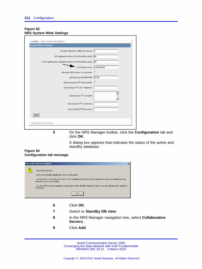
312 Configuration
Figure 82NRS System Wide Settings
5 On the NRS Manager toolbar, click the Configuration tab andclick OK.
A dialog box appears that indicates the status of the active andstandby database.
Figure 83Configuration tab message
6 Click OK.
7 Switch to Standby DB view.
8 In the NRS Manager navigation tree, select CollaborativeServers .
9 Click Add.
Nortel Communication Server 1000Converging the Data Network with VoIP Fundamentals
NN43001-260 03.12 3 March 2010
Copyright © 2003-2010 Nortel Networks. All Rights Reserved.
.
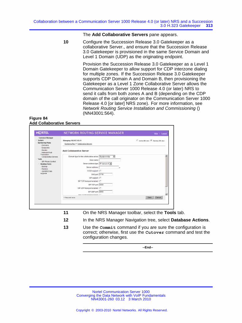
Collaboration between a Communication Server 1000 Release 4.0 (or later) NRS and a Succession3.0 H.323 Gatekeeper 313
The Add Collaborative Servers pane appears.
10 Configure the Succession Release 3.0 Gatekeeper as acollaborative Server., and ensure that the Succession Release3.0 Gatekeeper is provisioned in the same Service Domain andLevel 1 Domain (UDP) as the originating endpoint.
Provision the Succession Release 3.0 Gatekeeper as a Level 1Domain Gatekeeper to allow support for CDP interzone dialingfor multiple zones. If the Succession Release 3.0 Gatekeepersupports CDP Domain A and Domain B, then provisioning theGatekeeper as a Level 1 Zone Collaborative Server allows theCommunication Server 1000 Release 4.0 (or later) NRS tosend it calls from both zones A and B (depending on the CDPdomain of the call originator on the Communication Server 1000Release 4.0 [or later] NRS zone). For more information, seeNetwork Routing Service Installation and Commissioning ()(NN43001:564).
Figure 84Add Collaborative Servers
11 On the NRS Manager toolbar, select the Tools tab.
12 In the NRS Manager Navigation tree, select Database Actions.
13 Use the Commit command if you are sure the configuration iscorrect; otherwise, first use the Cutover command and test theconfiguration changes.
--End--
Nortel Communication Server 1000Converging the Data Network with VoIP Fundamentals
NN43001-260 03.12 3 March 2010
Copyright © 2003-2010 Nortel Networks. All Rights Reserved.
.

314 Configuration
Configuring the Succession Release 3.0 Gatekeeper
Step Action
1 Log on to Gatekeeper in Element Manager (for SuccessionRelease 3.0).
2 Select the GK Standby DB Admin, GK Zones, Add NetworkZone GK item.
The Add other Network Zone Gatekeeper pane appears.Figure 85Add other Network Zone Gatekeeper
3 Add the Communication Server 1000 Release 4.0 (or later) NRSas a Network Zone Gatekeeper using the same GatekeeperH.323 alias name as configured in Step 4.
A Succession Release 3.0 Network Zone Gatekeeper issimilar to a Communication Server 1000 Release 4.0 (or later)Collaborative Server.
4 Click the GK Standby Database Admin, Database Actionslink.
5 Use the SingleStepCutoverCommit command after you aresure that the configuration is correct. Otherwise, first use theCutover command to test the configuration.
--End--
Configuring the MCS 5100 system as a Collaborative ServerThe MCS 5100 can be configured as a collaborative server which supportsH.323 and SIP.
Nortel Communication Server 1000Converging the Data Network with VoIP Fundamentals
NN43001-260 03.12 3 March 2010
Copyright © 2003-2010 Nortel Networks. All Rights Reserved.
.

Zone configuration 315
The configuration for H.323 is the same as for another SuccessionRelease 3.0 Gatekeeper with the limitation that MCS 5100 can only beconfigured as a Level 0 Domain Collaborative Server. The MCS 5100cannot parse the H.323 LRQ messages that specify a Level 0 Domain ona per:call basis. So it always routes the call to a fixed Level 0 Domain.In this case, only the MCS 5100 H.323 alias name (configured as theCollaborative Server Gatekeeper alias name) and IP address is relevant.
For SIP calls, the MCS 5100 can be configured as a Level 1 or Level 0Domain Collaborative Server. The Service Domain on the NRS shouldmatch the Service Domain on the MCS 5100. A Level 1 Domain ispreferred, so the MCS 5100 can be used for calls that originate frommultiple Level 0 Domains without restriction.
Zone configurationUse Element Manager to configure zone properties:
The following properties can be configured.
• “Zone Basic Property and Bandwidth Management” (page 315)
• “Adaptive Network Bandwidth Management and CAC” (page 316)
• “Alternate Routing for Calls between IP stations” (page 322)
• “Branch Office Dialing Plan and Access Codes” (page 324)
• “Branch Office Time Difference and Daylight Saving Time Property”(page 325)
• “Emergency Service Information” (page 327)
Zone Basic Property and Bandwidth ManagementUse Element Manager to configure the branch office specific Zoneproperties using the Zone configuration screen required at the branchoffice. It is an alternative to Zone configuration using LD 117. Thefollowing procedure uses Zone 0 as an example.
Configuring branch office specific Zone properties
Step Action
1 In the Element Manager navigation tree, click System,IP Network, Zones, Zone 0, Zone Basic Property andBandwidth Management.
The Zone Basic Property and Bandwidth Managementwindow appears.
Nortel Communication Server 1000Converging the Data Network with VoIP Fundamentals
NN43001-260 03.12 3 March 2010
Copyright © 2003-2010 Nortel Networks. All Rights Reserved.
.

316 Configuration
Figure 86Zone Basic Property and Bandwidth Management
2 In the Input Value section, configure the following values:
• Zone Number (ZONE): 1
• Intrazone Bandwidth (INTRA_BW): 10000
• Intrazone Strategy (INTRA_STGY): Best Quality (BQ)
• Interzone Bandwidth (INTER_BW):10000
• Interzone Strategy (INTER_STGY):Best Quality (BQ)
• Resource Type (RES_TYPE):Shared (SHARED)
• Zone Intent (ZBRN): MO (MO)
• Description (ZDES):
At the branch office, (ZBRN) for branch office support must becleared. This parameter is only applicable to the correspondingzone at the main office.
3 Click Submit.
--End--
Adaptive Network Bandwidth Management and CACFor information on configuration rules and advanced configuration notesfor Adaptive Network Bandwidth Management and CAC, see “AdaptiveNetwork Bandwidth Management configuration” (page 281)
Nortel Communication Server 1000Converging the Data Network with VoIP Fundamentals
NN43001-260 03.12 3 March 2010
Copyright © 2003-2010 Nortel Networks. All Rights Reserved.
.

Zone configuration 317
Configuring Adaptive Network Bandwidth Management and CAC
WARNINGDo not configure Adaptive Network Bandwidth Management forZone 0 or Virtual Trunk zones.
Step Action
1 In the Element Manager navigation pane, click System, IPNetwork, Zones, Zone 1, Adaptive Network BandwidthManagement and CAC.
The Adaptive Network Bandwidth Management and CAC windowappears.
Figure 87Adaptive Network Bandwidth Management and CAC
2 Enable the Call Admission Control Feature (STATE) byselecting the check box. The other parameters can be adjustedas required.
3 In the Input Value section, configure the following parameters:
Nortel Communication Server 1000Converging the Data Network with VoIP Fundamentals
NN43001-260 03.12 3 March 2010
Copyright © 2003-2010 Nortel Networks. All Rights Reserved.
.

318 Configuration
• QoS Response Time Increase (ZQRT)
• QoS Response Time Interval (ZQRTI)
• Warning Alarm Threshold (ZQWAT)
• Unacceptable Alarm Threshold (ZQUAT)
• R Alarm Coefficient (CR)
• Packet Loss Alarm Coefficient (CPL)
• Delay Alarm Coefficient (CD)
• Jitter Alarm Coefficient (CJ)
• Coefficient of QoS (CQoS)
• Recent Validity Time Interval (CACVT)
4 Tandem the outbound branch office calls by configuring theNRS.
5 Tandem the inbound branch office calls by creating a dialing planwhich routes all calls destined for the branch office through themain office.
6 Click Submit.
--End--
The following table shows the fields in the Adaptive Network BandwidthManagement and CAC window, the field definitions, and the LD 117command equivalent.
Table 80Adaptive Network Bandwidth Management and CAC fields
Field title Field definition LD 117 equivalent
Enable Call AdmissionControl Feature (STATE)
Control the CAC feature for the Zone• Enable (select check box )
• disable (clear the check box)
ENL ZCACDIS ZCAC
QoS Response TimeIncrease (ZQRT)
Bandwidth limit increment, as apercentage of the QoS factor for theZone
CHG ZQRT
QoS Response TimeInterval (ZQRTI)
Time (in minutes) between bandwidthlimit increments
CHG ZQRTI
Warning Alarm Threshold(ZQWAT)
A QoS value, which is lower thanthis value, but higher than the Critical(Unacceptable) Alarm Threshold,triggers a Major Alarm.
CHG ZQWAT
Nortel Communication Server 1000Converging the Data Network with VoIP Fundamentals
NN43001-260 03.12 3 March 2010
Copyright © 2003-2010 Nortel Networks. All Rights Reserved.
.

Zone configuration 319
Field title Field definition LD 117 equivalent
Unacceptable AlarmThreshold (ZQUAT)
A QoS value, which is lower thanthis value, triggers an Unacceptable(Critical) Alarm.
CHG ZQUAT
R Alarm Coefficient (CR) The R (CR) coefficient is used tocalculate the QoS value for the Zone.
CHG CR
Packet Loss AlarmCoefficient (CPL)
The Packet Loss (Cpl) coefficient isused to calculate the QoS value for theZone.
CHG CPL
Delay Alarm Coefficient(CD)
The Delay (CD) coefficient is used tocalculate the QoS value for the Zone.
CHG CD
Jitter Alarm Coefficient (CJ) The Jitter (CJ) coefficient is used tocalculate the QoS value for the Zone.
CHG CJ
Coefficient of QoS (CQoS) The Coefficient of QoS (CQoS) is usedto calculate the overall QoS value forthe Zone.
CHG CQOS
Recent Validity TimeInterval (CACVT)
Amount of time (in hours) forzone:to:zone record validity. Afterthis interval expires, records for unusedzones are purged from the tables.
CHG CACVT
Command line interface configurationYou can also configure the Adaptive Network Bandwidth Managementfeature using LD 117.
Table 81LD 117 – Configure Adaptive Network Bandwidth Management
Command Description
CHG CACVT <Zone> <Interval> Configure the zone:to:zone record validity time interval,where:
• Zone = 1:255
• Interval = 1:(48):255
CHG CD <Zone> <Cd> Change the Cd coefficient in the formula that determineshow quickly an alarm reduces the Sliding Maximumbandwidth for the identified zone, where:• Zone = 1:255
• Cd = Cd coefficient = 1:(50):100
CHG CPL <Zone> <Cpl> Change the Cpl coefficient in the formula that determineshow quickly an alarm reduces the Sliding Maximumbandwidth for the identified zone, where:• Zone = 1:255
• Cpl = Cpl coefficient = 1:(50):100
Nortel Communication Server 1000Converging the Data Network with VoIP Fundamentals
NN43001-260 03.12 3 March 2010
Copyright © 2003-2010 Nortel Networks. All Rights Reserved.
.
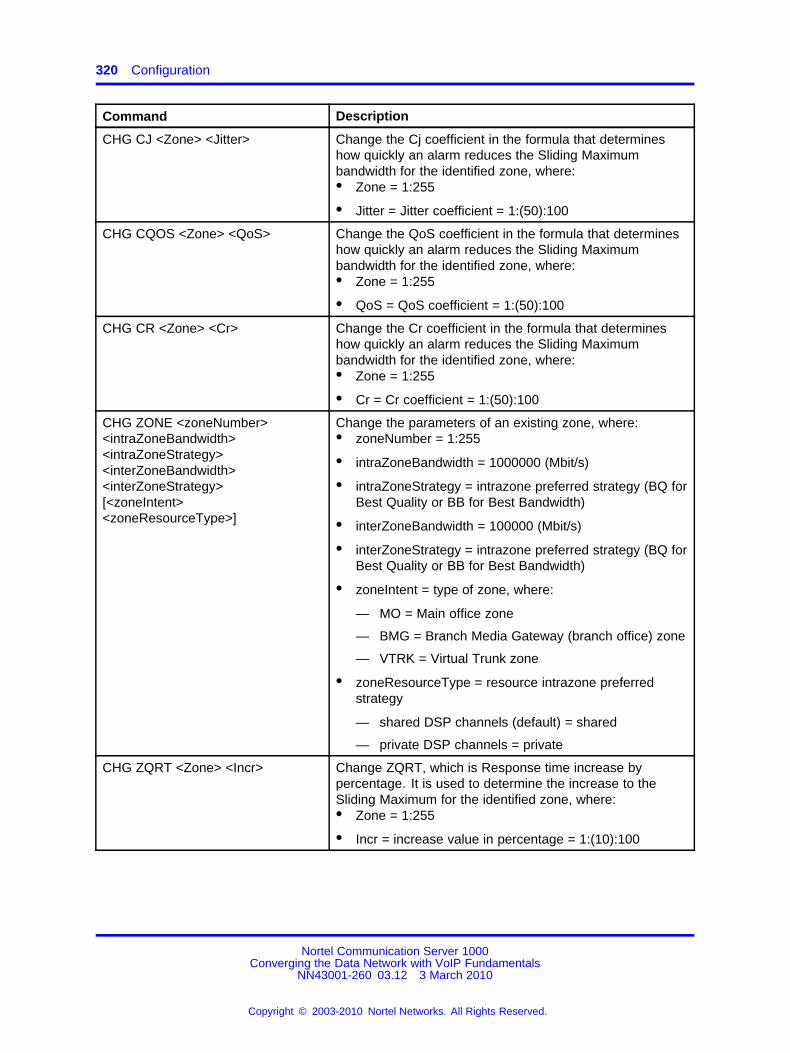
320 Configuration
Command Description
CHG CJ <Zone> <Jitter> Change the Cj coefficient in the formula that determineshow quickly an alarm reduces the Sliding Maximumbandwidth for the identified zone, where:• Zone = 1:255
• Jitter = Jitter coefficient = 1:(50):100
CHG CQOS <Zone> <QoS> Change the QoS coefficient in the formula that determineshow quickly an alarm reduces the Sliding Maximumbandwidth for the identified zone, where:• Zone = 1:255
• QoS = QoS coefficient = 1:(50):100
CHG CR <Zone> <Cr> Change the Cr coefficient in the formula that determineshow quickly an alarm reduces the Sliding Maximumbandwidth for the identified zone, where:• Zone = 1:255
• Cr = Cr coefficient = 1:(50):100
CHG ZONE <zoneNumber><intraZoneBandwidth><intraZoneStrategy><interZoneBandwidth><interZoneStrategy>[<zoneIntent><zoneResourceType>]
Change the parameters of an existing zone, where:• zoneNumber = 1:255
• intraZoneBandwidth = 1000000 (Mbit/s)
• intraZoneStrategy = intrazone preferred strategy (BQ forBest Quality or BB for Best Bandwidth)
• interZoneBandwidth = 100000 (Mbit/s)
• interZoneStrategy = intrazone preferred strategy (BQ forBest Quality or BB for Best Bandwidth)
• zoneIntent = type of zone, where:
— MO = Main office zone
— BMG = Branch Media Gateway (branch office) zone
— VTRK = Virtual Trunk zone
• zoneResourceType = resource intrazone preferredstrategy
— shared DSP channels (default) = shared
— private DSP channels = private
CHG ZQRT <Zone> <Incr> Change ZQRT, which is Response time increase bypercentage. It is used to determine the increase to theSliding Maximum for the identified zone, where:• Zone = 1:255
• Incr = increase value in percentage = 1:(10):100
Nortel Communication Server 1000Converging the Data Network with VoIP Fundamentals
NN43001-260 03.12 3 March 2010
Copyright © 2003-2010 Nortel Networks. All Rights Reserved.
.

Zone configuration 321
Command Description
CHG ZQRTI <Zone> <Interval> Change the QoS Response Time Interval while alarmsare not coming, to increase the Sliding Maximum for theidentified zone, where:• Zone = 1:255
• Interval = interval in minutes = 1:(5):120
CHG ZQUAT <Zone> <Thres> Change the QoS Unacceptable Alarm Threshold value forthe identified zone, where:• Zone = 1:255
• Thres = threshold value = 1:(75):99
ATTENTIONWhen the zone:to:zone QoS value drops below thethreshold value, the alarm is presented. This value mustbe below the value of ZQWAT.
CHG ZQWAT <Zone> <Thres> Change the QoS Warning Alarm Threshold value for theidentified zone, where:• Zone = 1:255
• Thres = threshold value = 1:(85):99
ATTENTIONWhen the zone:to:zone QoS value drops below thethreshold value, the alarm is presented. The value forZQWAT must be higher than the value of ZQUAT.
CHG ZQNL<Zonenumber> <level>
Change the Notification Level for the specified zone,where:• Zone = 1:255
• Level = 0:(2):4, where:
— Level 0 = All voice quality alarms are suppressed.
— Level 1 = All zone:based Unacceptable alarms.
— Level 2 = Allow all level 1 alarms PLUS zone:basedWarning alarms.
— Level 3 = Allow all level 1 and 2 alarms PLUSper:call Unacceptable alarms.
— Level 4 = Allow all level 1, 2, and 3 alarms PLUSper:call Warning alarms
Nortel Communication Server 1000Converging the Data Network with VoIP Fundamentals
NN43001-260 03.12 3 March 2010
Copyright © 2003-2010 Nortel Networks. All Rights Reserved.
.

322 Configuration
Command Description
NEW ZONE <zoneNumber>[<intraZoneBandwidth><intraZoneStrategy><interZoneBandwidth><interZoneStrategy><zoneIntent><zoneResoureType>]
• zoneNumber = 1:255
• intraZoneBandwidth = 1000000 (Mbit/s)
• intraZoneStrategy = BQ (Best Quality) or BB (BestBandwidth)
• interZoneBandwidth = 1000000 (Mbit/s)
• interZoneStrategy = intrazone preferred strategy(BQ=Best Quality) or BB (Best Bandwidth)
• zoneIntent = type of zone, where:
— MO = Main office zone
— BMG = Branch Media Gateway (branch office) zone
— VTRK = Virtual Trunk zone
• zoneResourceType = resource intrazone preferredstrategy
— shared DSP channels (default) = shared
— private DSP channels = private
DIS ZCAC <Zone> Disables the Call Admission Control (CAC) feature for thespecified zone, where Zone = 1:255.
ATTENTIONDisables the feature on a zone:by:zone basis.
ENL ZCAC <Zone> Enables the Call Admission Control (CAC) feature for thespecified zone, where Zone = 1:255.
ATTENTIONEnables the feature on a zone:by:zone basis.
Alternate Routing for Calls between IP stationsUse the following procedures for configuring Alternate Routing for Callsbetween IP stations.
Configuring Alternate Routing for Calls between IP stations
Step Action
1 In the Element Manager navigation tree, click System, IPNetwork, Zones.
Nortel Communication Server 1000Converging the Data Network with VoIP Fundamentals
NN43001-260 03.12 3 March 2010
Copyright © 2003-2010 Nortel Networks. All Rights Reserved.
.

Zone configuration 323
Figure 88Element Manager to access Zones
The Zones window appears.
2 In the Configuration section, click the Zone you areprogramming and click the plus sign to expand the choices underit.
3 Click Alternate Routing for Calls between IP Stations.
The Alternate Routing for Calls between IP Stations windowappears and displays the configuration parameters for the Zoneyou selected in the previous step.
Figure 89Alternate Routing for Calls between IP Stations
Nortel Communication Server 1000Converging the Data Network with VoIP Fundamentals
NN43001-260 03.12 3 March 2010
Copyright © 2003-2010 Nortel Networks. All Rights Reserved.
.

324 Configuration
4 Select the Enable Alternate Routing feature (ENL_ZALT)check box to enable the Alternative Call Routing for NetworkBandwidth Management feature.
5 In Alternate Routing Prefix Digits (ALTPrefix), enter amaximum of 7 digits.
6 Select the Re:route for All Calls (ALL_CALLS) check box toenable the feature for all calls.
7 Click Submit to enter the data.
--End--
Branch Office Dialing Plan and Access CodesUse the following procedures for configuring Branch Office Dialing Planand Access Codes.
Configuring Branch Office Dialing Plan and Access Codes
Step Action
1 In the Element Manager navigation tree, click System, IPNetwork, Zones, Zone 0, Branch Office Dialing Plan andAccess Codes.
The Zone Dialing Plan and Access Codes window appears.Figure 90Zone Dialing Plan and Access Codes
2 In the Input Value section, the following values must beconfigured:
Nortel Communication Server 1000Converging the Data Network with VoIP Fundamentals
NN43001-260 03.12 3 March 2010
Copyright © 2003-2010 Nortel Networks. All Rights Reserved.
.

Zone configuration 325
• Zone Number (ZONE)
• Prefix (ACB_DC1)
• Country Code/Trunk Code (ACB_DC2)
• Destination Network Code (ACB_DC3)
• Dialed Access Code (ACB_LOC_AC)
• New Access Code (ACB_LD_AC)
3 Click Submit.
--End--
Branch Office Time Difference and Daylight Saving Time PropertyUse the following procedures for configuring Branch Office TimeDifferences and Daylight Saving Time properties.
Configuring Branch Office Time Difference and Daylight Saving Timeproperties
Step Action
1 In the Element Manager navigation tree, click System, IPNetwork, Zones, Zone 0, Branch Office Time Difference andDaylight Saving Time Property.
The Time Difference and Daylight Saving Time window appears.
Nortel Communication Server 1000Converging the Data Network with VoIP Fundamentals
NN43001-260 03.12 3 March 2010
Copyright © 2003-2010 Nortel Networks. All Rights Reserved.
.

326 Configuration
Figure 91Time Difference and Daylight Saving Time
2 In the Input Value section, the following values must beconfigured:
• Zone Number (ZONE)
• Use Daylight Saving Time (USE_DST)
• Active Status of Daylight Saving Time (DST_ACT)
• Start Month (START_MON)
• Start Week (START_WEEK)
• Start Day (START_DAY)
• Start Hour (START_HOUR)
• End Month (END_MON)
• End Week (END_WEEK)
• End Day (END_DAY)
• End Hour (END_HOUR)
Nortel Communication Server 1000Converging the Data Network with VoIP Fundamentals
NN43001-260 03.12 3 March 2010
Copyright © 2003-2010 Nortel Networks. All Rights Reserved.
.

Zone configuration 327
3 Click Submit.
--End--
Emergency Service InformationUse the following procedures for configuring Emergency ServiceInformation.
Configuring Emergency Service Information
Step Action
1 In the navigation pane, click IP Telephony, Zone 0, ZoneEmergency Service Information.
The Zone Emergency Service Information window appears.Figure 92Zone Emergency Service Information
2 In the Input Value section, the following values must beconfigured:
• Zone Number (ZONE)
• Route number (ESN_ROUT)
• ESA Access Code (ESA_AC)
3 Click Submit.
--End--
The MG 1000B zone configurationZone parameters must be configured at both the main office Call Serverand MG 1000B CP PM. The procedure for configuration on the MG 1000BCP PM is similar to an IP Peer Network configuration, with the additionalBranch office:specific configuration outlined in this section.
Nortel Communication Server 1000Converging the Data Network with VoIP Fundamentals
NN43001-260 03.12 3 March 2010
Copyright © 2003-2010 Nortel Networks. All Rights Reserved.
.

328 Configuration
Zones are defined in LD 117 and applied to IP Phones in LD 11.
Time adjustments for zones are configured in LD 117 and defined relativeto the time set in LD 2.
For more information about configuring MG 1000B at the main office, seeBranch Office Installation and Commissioning (NN43001-314) ().
CAUTIONBefore and after an upgrade, perform a datadump (using LD 43EDD or Element Manager) on the CP PM or MGC to back upthe existing data.
Configuring the MG 1000B zone for the Branch office
Step Action
1 Set the current date and time.
See Software Input Output Reference — Administration(NN43001-611) ().
Table 82LD 2 – Define system time and date
Command Description
STAD dd mm yyyy hh mm ss Set the time and date:STAD DAY MONTH YEARHOUR MINUTE SECONDNote: You must have a level 2 password to set the timeand date.
2 Configure the Home Location Code (HLOC) and Virtual PrivateNetwork Identifier (VPNI).
Table 83LD 15 – Configure Customer Data Home Location Code and Virtual Private Network Identifier.
Prompt Response Description
REQ new/chg Add new data or change existing data.
TYPE NET ISDN and ESN Networking options
0:99 Range for Large System and CommunicationServer 1000E system
0:31 Range for Small System and Media Gateway1000B
...
CLID YES Allow Calling Line Identification Option
: ENTRY XX CLID entry to be configured
Nortel Communication Server 1000Converging the Data Network with VoIP Fundamentals
NN43001-260 03.12 3 March 2010
Copyright © 2003-2010 Nortel Networks. All Rights Reserved.
.

Zone configuration 329
Prompt Response Description
: : HLOC 100:9999999 Home location code (ESN) (3:7 digits)
ISDN YES Integrated Services Digital Network
: VPNI (0):16383 Virtual Private Network Identifier for BandwidthManagement Feature0 or X = disables feature1:16383 = enables feature<cr> = no change
3 Configure Vacant Number Routing (VNR).
VNR must be configured at the branch office. When a BranchUser is in Normal Mode, a call to that user arriving at the branchoffice is routed to the main office. VNR at the branch office andthe NRS configuration identifies the main office as the endpointfor that user.
VNR is routed through the Virtual Trunk and enables the NRSto centralize Numbering Plan definitions. To configure VNR,you must configure a Route List Index (RLI) with the DigitManipulation Index (DMI) in LD 86 set to 0 (no digit manipulationrequired) on the Virtual Trunk route.
Table 84LD 15 – Configure Vacant Number Routing.
Prompt Response Description
REQ NEW CHG Add new data, or change existing data
TYPE NET Configure networking
VNR YES Vacant Number Routing
: RLI 0:999 Route List Index as defined in LD 86
: FLEN 1:(16) Flexible length of digits expected
: CDPL 1:(10) Flexible length of VNR CDP
: UDPL 1:(19) Flexible length of VNR LOC
4 Configure the zone properties for IP telephony BandwidthManagement using LD 117 or Element Manager. At the branchoffice, this zone is used only for Bandwidth Managementpurposes. It does not have any associated time zone or dialingplan properties.
ATTENTIONThe branch office zone number and zone Bandwidth Managementparameters at the main office must match the corresponding branchoffice zone number and zone Bandwidth Management parametersat the branch office.
Nortel Communication Server 1000Converging the Data Network with VoIP Fundamentals
NN43001-260 03.12 3 March 2010
Copyright © 2003-2010 Nortel Networks. All Rights Reserved.
.

330 Configuration
WARNINGZone 0, the default zone, must not be configured as abranch office zone. Network Bandwidth Managementdoes not support Zone 0. If Zone 0 is configuredas a branch office zone, the Network BandwidthManagement feature will not be activated.
Table 85LD 117 – Define zone properties for branch office
Command Description
NEW ZONE <xxx><intraZoneBandwidth><intraZoneStrategy><interZoneBandwidth><interZoneStrategy><zoneResourceType>
Create a new zone with the following parameters:
• xxx = 1:255 zone number
• intraZoneBandwidth = Intrazone available bandwidth 0:1000 000 kbit/s (see Note 1)
• intraZoneStrategy = Intrazone preferred strategy (BQ forBest Quality)
• interZoneBandwidth = Interzone available bandwidth 0:1000 000 kbit/s (see Note 1)
• interZoneStrategy = Interzone preferred strategy (BQ forBest Quality or BB for Best Bandwidth)
• zoneResourceType = zone resource type (shared orprivate), where
— shared = Current default zone type. The IP Phonesconfigured in shared zones use DSP resourcesconfigured in shared zones. If all of the shared zonegateway channels are used, the caller receives anoverflow tone and the call is blocked. The orderof channel selection for the gateway channels is:a channel from the same zone as the IP Phone isconfigured, and then any available channel from theshared zone channels
— private = New zone type introduced by IPL 3.0. DSPchannels configured in a private zone are only usedby IP Phones that have also been configured for thatprivate zone. If more DSP resources are required bythese IP Phones than what are available in the zone,DSPs from other zones are used. However, IP Phonesconfigured in shared zones cannot use the privatezones channels. The order of selection for the gatewaychannels is: a channel from the same private zoneas the IP Phone is configured, and then any availablechannel from the pool of shared zones channels
Nortel Communication Server 1000Converging the Data Network with VoIP Fundamentals
NN43001-260 03.12 3 March 2010
Copyright © 2003-2010 Nortel Networks. All Rights Reserved.
.

Zone configuration 331
Command Description
For more information about Private/Shared Zone configuration, seeSignaling Server IP LineApplications Fundamentals (NN43001-125) .
Note 1: If the Network Bandwidth Management feature is going to be used, parametersintraZoneBandwidth and interZoneBandwidth must be set to the maximum configurable value. See“Bandwidth Management” (page 70).
5 Configure the parameters for IP Phone passwords andmodifications.
For more information about IP Phone installers password, seeBranch Office Installation and Commissioning (NN43001-314) ().
--End--
Configuring ESN, MG 1000B or SRG zones
WARNINGBefore and after an upgrade, perform a datadump (using LD 43EDD or through Element Manager) on the Call Server to backup the existing data.
Step Action
1 Configure the Home Location Code (HLOC), and the VirtualPrivate Network Identifier (VPNI).
Table 86LD 15 – Configure Customer Data Home Location Code and Virtual Private Network Identifier.
Prompt Response Description
REQ chg Change existing data.
TYPE NET ISDN and ESN Networking options
CUST Customer number
0:99 Range for Large System and CommunicationServer 1000E system
0:31 Range for Small System and Media Gateway1000B
... — —
CLID YES Allow Calling Line Identification Option
: ENTRY XX CLID entry to be configured
: : HLOC 100:9999999 Home location code (ESN) (3:7 digits)
Nortel Communication Server 1000Converging the Data Network with VoIP Fundamentals
NN43001-260 03.12 3 March 2010
Copyright © 2003-2010 Nortel Networks. All Rights Reserved.
.

332 Configuration
Prompt Response Description
ISDN YES Integrated Services Digital Network
: VPNI (0):16383 Virtual Private Network Identifier for BandwidthManagement Feature0 or X = disables feature1:16383 = enables feature<cr> = no change
2 Configure the branch office zone.
Configure the zone properties for IP telephony BandwidthManagement. Use LD 117 or Element Manager.
The branch office zone number and zone BandwidthManagement parameters at the main office must match thecorresponding branch office zone number and zone BandwidthManagement parameters at the branch office.
Table 87LD 117 – Define zone properties for branch office
Command Description
NEW ZONE <xxx><intraZoneBandwidth><intraZoneStrategy><interZoneBandwidth><interZoneStrategy><zoneResourceType>
Create a new zone with the following parameters:
• xxx = 0:255 zone number
• intraZoneBandwidth = Intrazone available bandwidth 0:1000 000 kbit/s See Note 1.
• intraZoneStrategy = Intrazone preferred strategy (BQ forBest Quality or BB for Best Bandwidth)
• interZoneBandwidth = Interzone available bandwidth 0:1000 000 kbit/s See Note 1.
• interZoneStrategy = Interzone preferred strategy (BQ forBest Quality or BB for Best Bandwidth)
• zoneResourceType = zone resource type (shared orprivate), where
— shared = Current default zone type. The IP Phonesconfigured in shared zones use DSP resourcesconfigured in shared zones. If all of the shared zones’gateway channels are used, the caller receives anoverflow tone and the call is blocked. The order ofchannel selection for the gateway channels is: achannel from the same zone as the IP Phone isconfigured, and then any available channel from theshared zone channels
— private = New zone type introduced by IPL 3.0. DSPchannels configured in a private zone are only used byIP Phones which have also been configured for thatprivate zone. If more DSP resources are required by
Nortel Communication Server 1000Converging the Data Network with VoIP Fundamentals
NN43001-260 03.12 3 March 2010
Copyright © 2003-2010 Nortel Networks. All Rights Reserved.
.

Zone configuration 333
Command Description
these IP Phones than what are available in the zone,DSPs from other zones are used. However, IP Phonesconfigured in shared zones cannot use the privatezone channels. The order of selection for the gatewaychannels is: a channel from the same private zoneas theIP Phone is configured, and then any availablechannel from the pool of shared zone channels
For more information about Private/Shared Zone configuration, seeSignaling Server IP Line Applications Fundamentals(NN43001-125)
Note 1: If the Network Bandwidth Management feature is going to be used, parametersintraZoneBandwidth and interZoneBandwidth must be set to the maximum configurable value. See“Bandwidth Management” (page 70).
WARNINGZone 0, the default zone, must not be configured as abranch office zone. Network Bandwidth Managementdoes not support Zone 0. If Zone 0 is configuredas a branch office zone, the Network BandwidthManagement feature will not be activated.
3 Define the zone parameters at the branch office. Use LD 117 orElement Manager.
Table 88LD 117 – Define zone parameters for the branch office.
Command Description
CHG ZBRN <Zone> <yes|no> Define a zone as a branch office zone.
CHG ZDST <Zone><yes|no><StartMonth><StartWeek><StartDay><StartHour><EndMonth><EndWeek><EndDay><EndHour>
If the branch office observes Daylight SavingsTime (DST), these parameters specify thestart and end of DST. During DST, the clockautomatically advances one hour forward.
CHG ZTDF <Zone><TimeDifferencefromMainOffice>
Specified in minutes, the time differencebetween the main office and branch office whenboth are not in DST.
CHG ZDES <Zone><ZoneDescription>
A name to render data display more meaningful.
4 Enable the features for the branch office zone in LD 117.
Nortel Communication Server 1000Converging the Data Network with VoIP Fundamentals
NN43001-260 03.12 3 March 2010
Copyright © 2003-2010 Nortel Networks. All Rights Reserved.
.

334 Configuration
Table 89LD 117—Enable features for MG 1000B zone.
Command Description
ENL ZBR <Zone> ALL Enables features for the branch office <zone>.
--End--
Abbreviated dialingAbbreviated Dialing must be configured at the main office and at thebranch office.
The main office and branch office must have the same configuration. TheDNs, zones, and Pretranslation Groups must be exactly the same in bothoffices.
Use the following procedures to configure Abbreviated dialing:
• “Configuring the Speed Call List ” (page 334)
• “Configuring Pretranslation Groups” (page 335)
• “Assigning Pretranslation Groups to the telephones” (page 336)
• “Configuring Incoming DID Digit Conversion (IDC)” (page 337)
The Pretranslation Group number does not need to be the same asthe number of the zone to which it is assigned. However, it does makeconfiguration more intuitive if the two values are the same.
Configuring the Speed Call List
Step Action
1 In LD 18, configure the Speed Call List (SCL) for each mainoffice zone.
Table 90LD 18—Configure Speed Call Lists (SCL) for each zone
Prompt Response Description
REQ NEW Add new data
TYPE SCL Speed Call List
LSNO 4:(16):31 Maximum number of DNs allowed for Speed Call Lists
DNSZ 0:(256):1000 Maximum number of DNs in Speed Call List
WRT (YES) NO Data is correct and can be updated in the data store
STOR 0:999 yyy...y Entry number and the digits stored with it
Nortel Communication Server 1000Converging the Data Network with VoIP Fundamentals
NN43001-260 03.12 3 March 2010
Copyright © 2003-2010 Nortel Networks. All Rights Reserved.
.

Zone configuration 335
Prompt Response Description
WRT (YES) NO Data is correct and can be updated in the data store
The STOR and WRT prompts are repeated in sequence for each number in the SCL.
2 Repeat to configure the SCL for each branch office zone.
3 In LD 18, configure the default SCL.
Table 91LD 18—Configure default Speed Call List
Prompt Response Description
REQ NEW Add new data
TYPE SCL Speed Call List
LSNO 0 Default SCL
DNSZ 4:(16):31 Maximum number of DNs allowed for Speed Call Lists
SIZE 0:(256):1000 Maximum number of DNs in Speed Call List
WRT (YES) NO Data is correct and can be updated in the data store
STOR <cr> Accept default
WRT (YES) NO Data is correct and can be updated in the data store.
--End--
Configuring Pretranslation Groups
Step Action
1 In LD 18, configure the Pretranslation Group for each main officezone.
ATTENTIONWhile not required, Nortel recommends that the Pretranslation Groupnumber (XLAT) be the same as the number of the zone to which itis assigned.
Table 92LD 18—Configure Pretranslation Group for each zone
Prompt Response Description
REQ NEW Add new data.
TYPE PRE Pretranslation Group
XLAT 1:8191 Group number. Correlates Pretranslation Group to Speed CallList.
: PRE 1:8190 Pretranslation Speed Call List Number. Corresponds to LSNOdefined in LD 18, TYPE=SCL
Nortel Communication Server 1000Converging the Data Network with VoIP Fundamentals
NN43001-260 03.12 3 March 2010
Copyright © 2003-2010 Nortel Networks. All Rights Reserved.
.
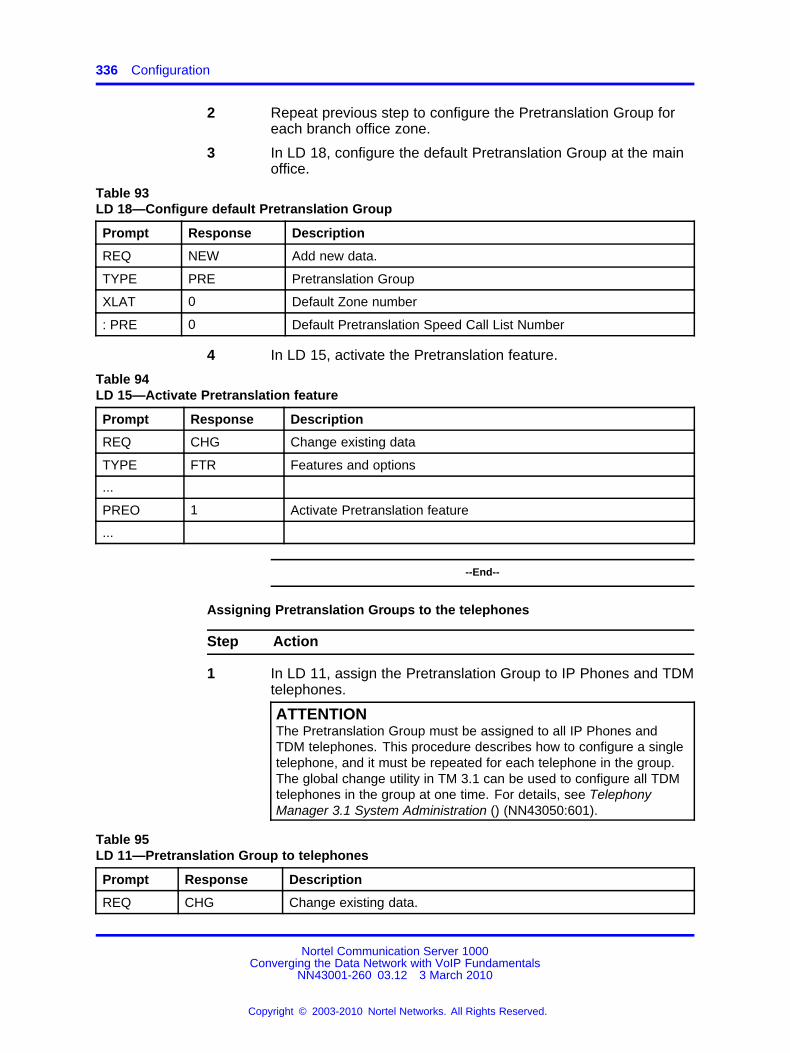
336 Configuration
2 Repeat previous step to configure the Pretranslation Group foreach branch office zone.
3 In LD 18, configure the default Pretranslation Group at the mainoffice.
Table 93LD 18—Configure default Pretranslation Group
Prompt Response Description
REQ NEW Add new data.
TYPE PRE Pretranslation Group
XLAT 0 Default Zone number
: PRE 0 Default Pretranslation Speed Call List Number
4 In LD 15, activate the Pretranslation feature.
Table 94LD 15—Activate Pretranslation feature
Prompt Response Description
REQ CHG Change existing data
TYPE FTR Features and options
...
PREO 1 Activate Pretranslation feature
...
--End--
Assigning Pretranslation Groups to the telephones
Step Action
1 In LD 11, assign the Pretranslation Group to IP Phones and TDMtelephones.
ATTENTIONThe Pretranslation Group must be assigned to all IP Phones andTDM telephones. This procedure describes how to configure a singletelephone, and it must be repeated for each telephone in the group.The global change utility in TM 3.1 can be used to configure all TDMtelephones in the group at one time. For details, see TelephonyManager 3.1 System Administration () (NN43050:601).
Table 95LD 11—Pretranslation Group to telephones
Prompt Response Description
REQ CHG Change existing data.
Nortel Communication Server 1000Converging the Data Network with VoIP Fundamentals
NN43001-260 03.12 3 March 2010
Copyright © 2003-2010 Nortel Networks. All Rights Reserved.
.

Zone configuration 337
Prompt Response Description
TYPE a...a Terminal type.
Type question mark (?) for a list of possible responses.
...
XLST (0):254 Pretranslation Group associated with the group.
...
2 Repeat previous step for each telephone in the group.
--End--
Configuring Incoming DID Digit Conversion (IDC)
Step Action
1 In LD 15, configure Flexible Code Restriction for IDC.
Table 96LD 15—Flexible Code Restriction for Incoming DID Digit Conversion
Prompt Response Description
REQ FCR Flexible Code Restriction
...
NFCR YES Enable new Flexible Code Restriction.
...
IDCA YES Incoming DID Digit Conversion allowed.
: DCMX 1:255 Maximum number of IDC conversion tables.
...
2 In LD 49, configure IDC.
Table 97LD 49—Incoming DID Digit Conversion (IDC)
Prompt Response Description
REQ NEW Add new data.
TYPE IDC Incoming Digit Conversion
DCNO 0:254 Digit Conversion tree number (IDC tree number).
Nortel Communication Server 1000Converging the Data Network with VoIP Fundamentals
NN43001-260 03.12 3 March 2010
Copyright © 2003-2010 Nortel Networks. All Rights Reserved.
.

338 Configuration
Prompt Response Description
...
IDGT<0:9999>
0:99990:9999
Incoming Digits (DN or range of DNs to be converted).Theexternal DN to be converted is output and the users enter theinternal DN. For example, to convert the external DN 3440 to510, enter:Prompt: ResponseIDGT: 34403440: 510
3 In LD 49, configure Flexible Code Restriction to allow all codes.
Table 98LD 49—Flexible Code Restriction
Prompt Response Description
REQ new Add new data.
TYPE FCR Flexible Code Restriction
CRNO (0):254 Code Restriction tree number
INIT Alow Allow all codes.
...
4 In LD 16, configure the Route Data Block to enable IDC on thisroute.
Table 99LD 16—Route Data Block
Prompt Response Description
REQ chg Change existing data
TYPE RDB Route Data Block
...
IDC YES Incoming DID Digit Conversion on this route.
: DCNO (0):254 Day IDC tree number
: NDNO 0:254 Night IDC tree number
...
--End--
Print branch office zone informationLD 117 contains commands to view branch office zones at the main officeCall Server.
Nortel Communication Server 1000Converging the Data Network with VoIP Fundamentals
NN43001-260 03.12 3 March 2010
Copyright © 2003-2010 Nortel Networks. All Rights Reserved.
.

Zone configuration 339
Table 100Print zone information
Command Description
PRT ZACB <Zone> Print a table of branch office zone dialing plan entries.
PRT ZBW <Zone> Print a table of zone bandwidth utilization.
PRT ZDES <DESMatchString> Print a table of the zone description entries.
PRT ZDP <Zone> Print a table of branch office zone dialing plan entries.
PRT ZDST <Zone> Print a table of branch office zone time adjustment propertiesentries.
PRT ZESA <Zone> Print a table of branch office zone Emergency ServicesAccess parameters.
PRT ZONE ALL Print zone information for all zones.
PRT ZONE 0:255 Print zone information for a specific zone.
PRT ZTDF <Zone> Print a table of branch office zone time adjustment propertiesentries.
PRT ZTP [<Zone>] Print a table of branch office zone time adjustment propertiesentries.
Enable/disable branch office zone featuresLD 117 contains commands to enable and disable features for the branchoffice zones.
Table 101LD 117—Enable/Disable branch office zone features
Command Description
ENL ZBR [<Zone>] [ALL] [LOC] [ESA] [TIM] Enable features for the branch office zone. If nospecific features are specified, ALL is assumed.
DIS ZBR [<Zone>] [ALL] [LOC] [ESA] [TIM] Disable features of the branch office zone. If nospecific features are specified, ALL is assumed.
CAUTIONWhen a zone is created, its default state is enabled.
Zone 0 must be configured in LD 117 first before other zonesare configured or all calls associated with Zone 0 are blocked.
View status of branch office zone at main office Call ServerLD 117 contains commands to review the status of the main office CallServer.
Nortel Communication Server 1000Converging the Data Network with VoIP Fundamentals
NN43001-260 03.12 3 March 2010
Copyright © 2003-2010 Nortel Networks. All Rights Reserved.
.

340 Configuration
Table 102LD 117—Display zone status
Command Description
STAT ZONE [<Zone>] Display zone status table
STAT ZBR [<Zone>] Display status of branch office zones.
Change/print Proactive Voice Quality notification levelsThe Proactive Voice Quality (PVQ) notification level can be changed ona zone:by:zone basis so that a particular zone, such as a branch officezone, is monitored more closely than others. LD 117 contains commandsfor changing and viewing the notification level for a zone.
ATTENTIONThe notification level for a branch office zone must be configured the same atboth the main office and the branch office.
Table 103LD 117—Change/print PVQ notification levels
Command Description
CHG ZQNL ALL <Level> Change the notification level for all zones.
CHG ZQNL <Zone> <Level Change the notification level for the specified zone.
PRT ZQNL ALL Print a table of the notification level for all zones.
PRT ZQNL <Zone> Print a table of the notification level for the specified zone.
Print PVQ statisticsLD 117 contains a command to print PVQ statistics for the branch officezone.
Table 104LD 117—PVQ statistics
Command Description
PRT ZQOS <zone> Print the PVQ statistics for the branch office zone.
DiagnosticsUse the following tables to obtain the status of a particular zone.
Command line interface diagnosticsLD 117 contains commands to obtain the status of a particular zone.
Nortel Communication Server 1000Converging the Data Network with VoIP Fundamentals
NN43001-260 03.12 3 March 2010
Copyright © 2003-2010 Nortel Networks. All Rights Reserved.
.
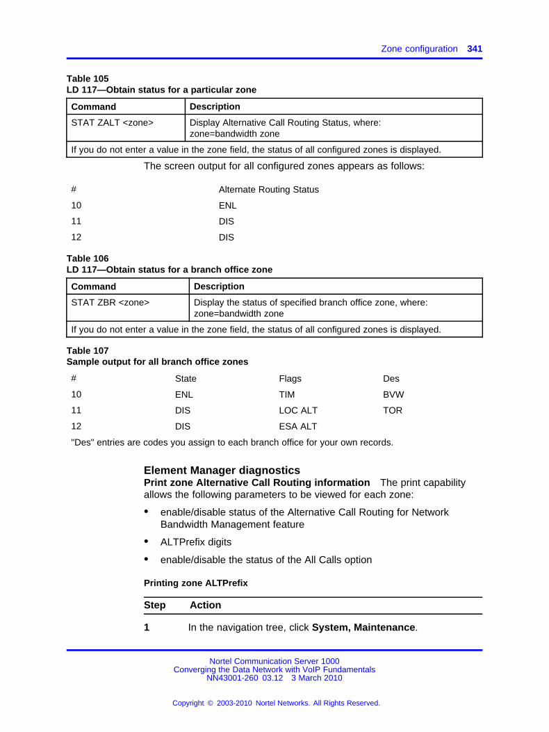
Zone configuration 341
Table 105LD 117—Obtain status for a particular zone
Command Description
STAT ZALT <zone> Display Alternative Call Routing Status, where:zone=bandwidth zone
If you do not enter a value in the zone field, the status of all configured zones is displayed.
The screen output for all configured zones appears as follows:
# Alternate Routing Status
10 ENL
11 DIS
12 DIS
Table 106LD 117—Obtain status for a branch office zone
Command Description
STAT ZBR <zone> Display the status of specified branch office zone, where:zone=bandwidth zone
If you do not enter a value in the zone field, the status of all configured zones is displayed.
Table 107Sample output for all branch office zones
# State Flags Des
10 ENL TIM BVW
11 DIS LOC ALT TOR
12 DIS ESA ALT
"Des" entries are codes you assign to each branch office for your own records.
Element Manager diagnosticsPrint zone Alternative Call Routing information The print capabilityallows the following parameters to be viewed for each zone:
• enable/disable status of the Alternative Call Routing for NetworkBandwidth Management feature
• ALTPrefix digits
• enable/disable the status of the All Calls option
Printing zone ALTPrefix
Step Action
1 In the navigation tree, click System, Maintenance.
Nortel Communication Server 1000Converging the Data Network with VoIP Fundamentals
NN43001-260 03.12 3 March 2010
Copyright © 2003-2010 Nortel Networks. All Rights Reserved.
.

342 Configuration
The Maintenance window appears.Figure 93System Maintenance
2 Select the Select by Functionality option button.
The Select by Functionality window appears.
Nortel Communication Server 1000Converging the Data Network with VoIP Fundamentals
NN43001-260 03.12 3 March 2010
Copyright © 2003-2010 Nortel Networks. All Rights Reserved.
.

Zone configuration 343
Figure 94Select by Functionality
3 Click Zone diagnostics.
The Maintenance Commands for Zones window appears.
You can also access this page from IP Network, Zones andclick on Maintenance Commands for Zones (LD 117).
Figure 95Maintenance Commands for Zones
Nortel Communication Server 1000Converging the Data Network with VoIP Fundamentals
NN43001-260 03.12 3 March 2010
Copyright © 2003-2010 Nortel Networks. All Rights Reserved.
.

344 Configuration
4 In the Action list, select Print Zone Alternate PrefixInformation (PRT ZALT).
Figure 96Maintenance Commands for Zones Action list
5 In the Zone Number list, select ALL or a specific zone number.
6 Click Submit.
The Maintenance Commands for Zones window appears, thatdisplays the statistics for the specified zone or zones. A blankfield indicates that the statistic is either not available or notapplicable to that zone.
--End--
Show status of Alternative Call Routing The Show Status functionalitydisplays the enable/disable status of Alternative Call Routing for theNetwork Bandwidth Management feature. The configured zones and thestatus of the feature for each zone can be listed.
Showing the status of Alternative Call Routing
Step Action
1 In the navigation tree, click System, Maintenance.
The Maintenance window appears. See Figure 93 "SystemMaintenance" (page 342).
2 Click Select by Functionality.
The Select by Functionality window appears. See Figure 94"Select by Functionality" (page 343).
Nortel Communication Server 1000Converging the Data Network with VoIP Fundamentals
NN43001-260 03.12 3 March 2010
Copyright © 2003-2010 Nortel Networks. All Rights Reserved.
.

Zone configuration 345
3 Click Zone diagnostics.
The Maintenance Commands for Zones window appears. SeeFigure 97 "Show Alternate Routing Status (STAT ZALT)" (page345).
4 From the Actions list, select Show Alternate Routing Status(STAT ZALT).
See Figure 97 "Show Alternate Routing Status (STAT ZALT)"(page 345).
Figure 97Show Alternate Routing Status (STAT ZALT)
5 In the Zone Number list, select ALL.
6 Click Submit to enter the data.
The window updates with the data associated with that zone.See Figure 97 "Show Alternate Routing Status (STAT ZALT)"(page 345) for a typical example of the results.
--End--
MaintenanceThe features in this section can be maintained using Element Manager orLD 117.
Adaptive Network Bandwidth Management for CACThe CAC parameters, intrazone, and interzone statistics for one of morezones are available in Element Manager from the Zones window.
Nortel Communication Server 1000Converging the Data Network with VoIP Fundamentals
NN43001-260 03.12 3 March 2010
Copyright © 2003-2010 Nortel Networks. All Rights Reserved.
.

346 Configuration
Displaying CAC parameters for one or more zones
Step Action
1 In Element Manager navigation tree, select System, IP Network,Zones.
The Zones window appears.
2 Click Maintenance Commands for Zones (LD 117).
The Maintenance Commands for Zones pane appears and listsall the configured zones and the intrazone statistics by default.
3 In the Action list, select Print Adaptive Network BandwidthManagement and CAC Parameters (PRT ZCAC).Figure 98Zone action list
4 In the Zone Number list, select ALL or a specific zone numberto display statistics for a specific zone.
5 Click Submit.
The Maintenance Commands for Zones window appears, whichdisplays the statistics for the specified zone or zones. A blankfield indicates that the statistic is not available or not applicableto that zone.
Nortel Communication Server 1000Converging the Data Network with VoIP Fundamentals
NN43001-260 03.12 3 March 2010
Copyright © 2003-2010 Nortel Networks. All Rights Reserved.
.

Zone configuration 347
Figure 99Element Manager CAC parameters
--End--
Table 108LD 117—Display Adaptive Network Bandwidth Management information
Command Description
CLR CACR<Near Zone><Near VPNI><Far Zone><Far VPNI>
Clear zone:to:zone record for near (VPNI:Zone) or far (VPNI:Zone) zones,where:• Near Zone = 1:255
• Near VPNI = 1:16383
• Far Zone = 1:255
• Far VPNI = 1:16383
PRT INTRAZONE<zone>
Print intrazone statistics for the identified zones, where zone = ALL or 1:255The output of this command displays the following information:
• Zone
• State = ENL/DIS
• Type = PRIVATE/SHARED
• Strategy = BB/BQ
• MO/BMG/VTRK = ZoneIntent
• Bandwidth = kbit/s
• Usage = kbit/s
• Peak = %
Nortel Communication Server 1000Converging the Data Network with VoIP Fundamentals
NN43001-260 03.12 3 March 2010
Copyright © 2003-2010 Nortel Networks. All Rights Reserved.
.
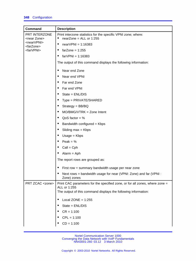
348 Configuration
Command Description
PRT INTERZONE<near Zone><nearVPNI><farZone><farVPNI>
Print interzone statistics for the specific VPNI zone; where:• nearZone = ALL or 1:255
• nearVPNI = 1:16383
• farZone = 1:255
• farVPNI = 1:16383
The output of this command displays the following information:
• Near end Zone
• Near end VPNI
• Far end Zone
• Far end VPNI
• State = ENL/DIS
• Type = PRIVATE/SHARED
• Strategy = BB/BQ
• MO/BMG/VTRK = Zone Intent
• QoS factor = %
• Bandwidth configured = Kbps
• Sliding max = Kbps
• Usage = Kbps
• Peak = %
• Call = Cph
• Alarm = Aph
The report rows are grouped as:
• First row = summary bandwidth usage per near zone
• Next rows = bandwidth usage for near (VPNI: Zone) and far (VPNI :Zone) zones
PRT ZCAC <zone> Print CAC parameters for the specified zone, or for all zones, where zone =ALL or 1:255The output of this command displays the following information:
• Local ZONE = 1:255
• State = ENL/DIS
• CR = 1:100
• CPL = 1:100
• CD = 1:100
Nortel Communication Server 1000Converging the Data Network with VoIP Fundamentals
NN43001-260 03.12 3 March 2010
Copyright © 2003-2010 Nortel Networks. All Rights Reserved.
.

Zone configuration 349
Command Description
• CJ = 1:100
• CQOS = 1:100
• ZQRT = 1:100
• ZQRTI = 10:120
• ZQUAT = 1:99
• ZQWAT =1:99
• CACVT = 1:255
Command line interface maintenance To view sample output for PRTcommands, see Figure 23 "Sample output for prt intrazone command"(page 87) and Figure 24 "Sample output for prt interzone command" (page87).
Alternative Call Routing for Network Bandwidth Management
Table 109LD 117—Enable and disable Alternative Call Routing for a zone
Command Description
ENL ZALT <zone> Enable Alternative Call Routing for BandwidthManagement for the zone specified, where:Input zone number (1:255).Configure the branch office zone using LD 117at the main office.
DIS ZALT <zone> Disable Alternative Call Routing for BandwidthManagement for the zone specified.
ENL ZBR <zone> [ALL] [LOC][ESA][TIM][ALT] Enable features for the branch office zone. Ifyou do not input features, then all are enabled.
DIS ZBR [ALL] [LOC][ESA][TIM][ALT] Disable features for the branch office zone. Ifyou do not input features, then all are disabled.
The system responds with ok, if operation is successful.
Table 110LD 117—Configure Alternate Prefix number for a particular zone and the All Calls option
Command Description
CHG ZALT <zone> <ALTPrefix> [<reroute allcalls>]
Change ALTPrefix number for zone.
<zone> Input zone number 1:255Configure the branch office zone using LD117 at the main office.
Nortel Communication Server 1000Converging the Data Network with VoIP Fundamentals
NN43001-260 03.12 3 March 2010
Copyright © 2003-2010 Nortel Networks. All Rights Reserved.
.

350 Configuration
Command Description
<ALTPrefix> A digit string, of up to 7 digits, added to thestart of the dialed number, if the call will notbe routed through the WAN (due to lack ofbandwidth, poor QoS, or feature is configuredfor all calls).
[<rereoute all calls>] Allow or Deny Alternative Call Routing for allcalls, where:• (NO) = deny
• YES = allow
Table 111LD 117—Print Alternate Prefix number for a particular zone
Command Description
PRT ZALT <zone> Print the ALTPrefix assigned to a particularzone and if the feature operates for all callsfrom that zone, where:
<zone> Input zone number 1:255If you do not input a zone number, the systemprints the information for all configured zones.
Table 112Sample Print Alternate Prefix number output
# ZALT Alternate Prefix All Calls AlarmsSuppressionTime
10 ENL 100 YES 50
11 ENL 101 YES 0
12 DIS 102 NO 1000
Table 113LD 117—Change and Print Zone Alarm Suppression Time Interval
Command Description
CHG ZAST <zone> <Alarm SuppressionInterval>
Change Suppression Time Interval for QoSalarms related to Alternative Call Routing forNetwork Bandwidth Management feature forzone specified. Time Interval is measuredin seconds from the time the last alarm wasprinted.Default is 0. Range is 0 : 3600 seconds.
PRT ZAST <zone> Print Suppression Time Interval for QoS alarmsrelated to Alternative Call Routing for theNetwork Bandwidth Management feature forzone specified. No entry for zone numberresults in printout for all zones.
Nortel Communication Server 1000Converging the Data Network with VoIP Fundamentals
NN43001-260 03.12 3 March 2010
Copyright © 2003-2010 Nortel Networks. All Rights Reserved.
.

Zone configuration 351
Table 114Sample Change and Print Zone Alarm Suppression Time Interval output
# Alarms Suppression Time
10 50
11 0
12 1000
Where # is the column header for zone number.
Element Manager maintenanceEnable zone Branch Office behavior You can configure the AlternativeCall Routing for the Network Bandwidth Management feature while youconfigure the zone Branch Office behavior.
Enabling a zone Branch Office behavior
Step Action
1 In the Element Manager navigation tree, select System,Maintenance.
The Maintenance pane appears. See Figure 93 "SystemMaintenance" (page 342).
2 Click Select by Functionality.
The Select by Functionality window appears. See Figure 94"Select by Functionality" (page 343).
3 Click Zone diagnostics.
The Maintenance Commands for Zones window appears.
4 From the Action list, select Enable a Zone’s Branch OfficeBehavior (ENL ZBR).
Nortel Communication Server 1000Converging the Data Network with VoIP Fundamentals
NN43001-260 03.12 3 March 2010
Copyright © 2003-2010 Nortel Networks. All Rights Reserved.
.

352 Configuration
Figure 100Enable zone Branch Office behavior
5 From the Zone Number list, select the zone number you want toconfigure.
6 Select the Alternate Routing for Branch check box to enablethe feature.
7 Click Submit.
The window updates with new configuration data for the zoneyou specified.
--End--
Suppress AlarmsUse the following procedure to suppress alarms QoS0038 and QoS0039for a configurable amount of time (0 : 3600 seconds).
Suppressing Alternate Call Routing for alarms
Step Action
1 Click System, IP Network, Zones
2 Select the Zone you are programming by clicking the plus signto expand the choices under it.
3 Click Alternate Routing for Calls between IP Stations.
Nortel Communication Server 1000Converging the Data Network with VoIP Fundamentals
NN43001-260 03.12 3 March 2010
Copyright © 2003-2010 Nortel Networks. All Rights Reserved.
.

SIP Line service 353
4 In the Alarm Suppression Time Period (ZAST) box, enter thedesired time period.
Figure 101Alarm Suppression Time Period (ZAST)
5 Click Submit to enter the data.
--End--
SIP Line serviceUse Element Manager (EM) and BCC applications running inside theCommunication Server 1000 Unified Common Manager (UCM) toconfigure and enable SIP Line Service for Communication Server 1000.
The SIP Line service package, 417, must be installed in order to enableSIP Line service on Communication Server 1000. The SIP Line service isenabled at the customer level.
A new SIP Line Service link exists on the customer page inside EM.Package 417 must be installed to activate the link. The following figure,Figure 102 "Customer edit page for SIP Line service" (page 354)shows theEdit page for SIP Line Service in EM.
Nortel Communication Server 1000Converging the Data Network with VoIP Fundamentals
NN43001-260 03.12 3 March 2010
Copyright © 2003-2010 Nortel Networks. All Rights Reserved.
.

354 Configuration
Figure 102Customer edit page for SIP Line service
Nortel Communication Server 1000Converging the Data Network with VoIP Fundamentals
NN43001-260 03.12 3 March 2010
Copyright © 2003-2010 Nortel Networks. All Rights Reserved.
.

355.
AppendixSubnet mask conversion
Subnet mask conversion from CIDR to dotted decimal formatSubnet masks are expressed in Classless InterDomain Routing (CIDR)format, appended to the IP address, such as 10.1.1.1/20. The subnetmask must be converted from CIDR format to dotted decimal format toconfigure IP addresses.
The CIDR format expresses the subnet mask as the number of bitscounted from the most significant bit of the first IP address field. Acomplete IP address consists of 32 bits. A typical CIDR format subnetmask is in the range from /9 to /30. Each decimal number field in thedotted decimal format has a value from 0 to 255, where decimal 255represents binary 1111 1111.
Follow the steps in the following procedure to convert a subnet mask fromCIDR format to dotted decimal format.
Converting a subnet mask from CIDR formatto dotted decimal format
Step Action
1 Divide the CIDR format value by 8.
The result is a quotient (a zero or a positive number) and aremainder between 0 and 7.
2 The quotient designates the number of dotted decimal fieldscontaining 255.
In the example above, the subnet mask in CIDR format is/20. Twenty divided by eight equals a quotient of two, with aremainder of four. Therefore, the first two fields of the subnetmask in dotted decimal format are 255.255.
3 Use Table 115 "CIDR format remainders" (page 356)to obtainthe dotted decimal value for the field following the last field thatcontains 255.
Nortel Communication Server 1000Converging the Data Network with VoIP Fundamentals
NN43001-260 03.12 3 March 2010
Copyright © 2003-2010 Nortel Networks. All Rights Reserved.
.

356 Subnet mask conversion
In the example of /20, the remainder is four. In Table 115 "CIDRformat remainders" (page 356), a remainder of four equals abinary value of 1111 0000 and the dotted decimal value of thenext field is 240. Therefore the first three fields of the subnetmask are 255.255.240.
4 The last field in the dotted decimal format has a value of 0.Therefore, the complete subnet mask in dotted decimal formatis 255.255.240.0.
--End--
Table 115CIDR format remainders
Remainder of CIDRformat value
divided by eight Binary value Dotted decimal value
0 0000 0000 0
1 1000 0000 128
2 1100 0000 192
3 1110 0000 224
4 1111 0000 240
5 1111 1000 248
6 1111 1100 252
7 1111 1110 254
Nortel Communication Server 1000Converging the Data Network with VoIP Fundamentals
NN43001-260 03.12 3 March 2010
Copyright © 2003-2010 Nortel Networks. All Rights Reserved.
.

357.
AppendixPort number tables
All ports specified in the following tables are Listen ports and specify thedestination IP address and port number. The tables do not specify thesource IP address or port.
The Task column specifies the software task listening on the specified port.
NavigationThis appendix contains port number tables for all Meridian 1 and CS1000M VoIP products.
“Ephemeral ports” (page 358)
“VXWorks Call Server port numbers” (page 358)
“Voice Gateway Media Card port numbers” (page 363)
“Media Gateway Controller port numbers” (page 371)
“Co-resident (Linux) Call Server port numbers” (page 377)
“Signaling Server port numbers” (page 382)
“SIP Lines Gateway Port Numbers” (page 388)
“Element Manager Port Numbers” (page 393)
“Network Routing Service Port Numbers” (page 398)
“Unified Communications Manager Port Numbers” (page 403)
“Telephony Manager port numbers” (page 407)
“IP Phone port numbers” (page 409)
“Remote Office port numbers” (page 410)
“CallPilot port numbers” (page 410)
“Application Gateway (AG) 1000 port numbers” (page 413)
“Contact Center 6.0 port numbers” (page 414)
“TLAN subnet stateless packet filtering” (page 414)
Nortel Communication Server 1000Converging the Data Network with VoIP Fundamentals
NN43001-260 03.12 3 March 2010
Copyright © 2003-2010 Nortel Networks. All Rights Reserved.
.

358 Port number tables
“TLAN subnet stateful packet filtering” (page 415)
“ELAN subnet packet filtering” (page 417)
Ephemeral portsEphemeral ports are short lived ports that are dynamically assigned.Typically ephemeral ports are assigned on the client side of a TCP or UDPinteraction. With FTP, ephemeral ports are also assigned on the serverside as part of the protocol.
The most effective method to manage ephemeral ports in a firewall isthrough the use of connection tracking. These features examine theapplication protocol (e.g. FTP, RPC) to open the required firewall portstemporarily. Connection tracking for TCP, FTP is commonly available.UDP connection tracking is availble in some firewalls. RPC connectiontracking is no longer required with CS 1000 release 6.0 as fixed serverports are used.
When connection tracking is not used in firewalls for TCP, RPC or FTPprotocols it is necessary to open all the ports in the ephemeral port ranges.
Linux considerationsThere can be various applications deployed and provisioned on a Linuxserver. Therefore, for any given Linux server, you must consider both thedeployed applications (e.g. Call Server, Signaling Server, etc) and theprovisioned applications (e.g. on the Signaling Server - VTRK, LTPS, etc).when determining the set of ports required.
VXWorks Call Server port numberswhere
MGMT = ManagementSC = System Control
Table 116VXWorks Call Server port numbers
Task L4 protocol (TCP/UDP)
Portnumberor range
Interface SourceElement
Description
Comments M = Mandatory,alwaysopen. D= Default,includedin ARDefaultrules filen/a = not
Nortel Communication Server 1000Converging the Data Network with VoIP Fundamentals
NN43001-260 03.12 3 March 2010
Copyright © 2003-2010 Nortel Networks. All Rights Reserved.
.

VXWorks Call Server port numbers 359
controlledby AR.
SC ESP (protocolnumber50)
ELAN Any CS1Kelement
IPsec,ESP -EncapulatingSecurityPayload
Requiredif ISSS isused.
MGMT TCP 20 ELAN MGC,VGMC,SS, TM,GR CS,mate CS,backupservers,managementstations
FTP dataport
Not Req’dif TCPconnectiontrackingused.
MGMT TCP 21 ELAN MGC,VGMC,SS, TM,GR CS,mate CS,backupservers,managementstations
FTP Control Port
Internaland external filetransfers
MGMT TCP 22 ELAN UCM, managementstations
SSH SecureInteractivelogon, filetransfers
SC TCP 111 ELAN Sunrpc-portmapper
Open butnot used.Can beblocked inFirewall.
MGMT TCP 513 ELAN SS, Managementstations
rlogin RemoteLogin
Nortel Communication Server 1000Converging the Data Network with VoIP Fundamentals
NN43001-260 03.12 3 March 2010
Copyright © 2003-2010 Nortel Networks. All Rights Reserved.
.

360 Port number tables
Task L4 protocol (TCP/UDP)
Portnumberor range
Interface SourceElement
Description
Comments M = Mandatory,alwaysopen. D= Default,includedin ARDefaultrules filen/a = notcontrolledby AR.
SC TCP 600-1023
ELAN MGC,VGMC,SS, TM,GR CS,mate CS,backupservers,managementstations
Ephemeral portsfor FTPdata transfers &RLOGIN
Typicallyhandledusing TCPand FTPconnectiontrackingin thefirewalls
SC TCP 1024-5000
ELAN UCM,MGC,VGMC,SS, TM,GR CS,mate CS,backupservers,managementstations
Ephemeral portsfor TCP
Typicallyhandledusing TCPconnectiontrackingin thefirewalls
SC TCP 5007 ELAN High AvailabilityCommunicationManager
Open butnot used.Can beblocked inFirewall.
SC TCP 6666 ELAN UCM ConfigProcess
Used forSNMP andNTP configuration propagation.
SC TCP 8888 ELAN ContactCenter,Call Pilot,MLS, SS
AML 3rd PartyCall Control
Nortel Communication Server 1000Converging the Data Network with VoIP Fundamentals
NN43001-260 03.12 3 March 2010
Copyright © 2003-2010 Nortel Networks. All Rights Reserved.
.

VXWorks Call Server port numbers 361
Task L4 protocol (TCP/UDP)
Portnumberor range
Interface SourceElement
Description
Comments M = Mandatory,alwaysopen. D= Default,includedin ARDefaultrules filen/a = notcontrolledby AR.
SC TCP 15000 ELAN MGC,VGMC,SS
pbxLink
SC TCP 15081 ELAN EM XmsgServer
For CS 1000 ElementManager
SC TCP 32781 ELAN MGC Signalingfor Sets& IPEcards onMGC
SC TCP 32784 ELAN MGC IPMGTTY
SC TCP 32788 ELAN MGC RPCMAIN /RPC GW
preassigned RPCport.
SC TCP 32789 ELAN MGC RPC INSTALL/RPC GWINSTALL
preassigned RPCport.
SC UDP 69 ELAN SS (TPS),VGMC(TPS)
tFTPd Tone andCadenceFile Transfers
SC UDP 111 ELAN MGC Sunrpc-portmapper
RPC Service for MGC
SC UDP 123 ELAN ExternalNTP Server
NTP Time Synchronization.Sourceport 500.
Nortel Communication Server 1000Converging the Data Network with VoIP Fundamentals
NN43001-260 03.12 3 March 2010
Copyright © 2003-2010 Nortel Networks. All Rights Reserved.
.

362 Port number tables
Task L4 protocol (TCP/UDP)
Portnumberor range
Interface SourceElement
Description
Comments M = Mandatory,alwaysopen. D= Default,includedin ARDefaultrules filen/a = notcontrolledby AR.
MGMT UDP 161 ELAN ManagementSystems,TM
SNMPquery
SC UDP 500 ELAN Any CS1Kelement
IPsecIKE
Requiredif ISSSis used.Sourceport 500
SC UDP 600-1023
ELAN MGC Ephemeral UDPports forSun RPCportmapperrequests
MGMT UDP 1929 ELAN TM DBA CDR/TRF
Used byTM
MGMT UDP 2058-2185
ELAN TM DBAData
Used byTM
SC UDP 5018 ELAN HA CSmateELAN
High AvailabilityCommunications
HA Callserveronly.
SC UDP 15000 ELAN MGC,VGMC,GR CS,HS CSMate
rudp HB source port15000
SC UDP 15010 ELAN SS, MGC,VGMC,inactiveCS
AFS source port15010
Nortel Communication Server 1000Converging the Data Network with VoIP Fundamentals
NN43001-260 03.12 3 March 2010
Copyright © 2003-2010 Nortel Networks. All Rights Reserved.
.
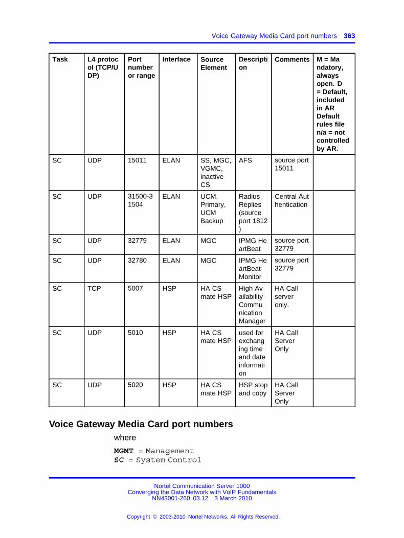
Voice Gateway Media Card port numbers 363
Task L4 protocol (TCP/UDP)
Portnumberor range
Interface SourceElement
Description
Comments M = Mandatory,alwaysopen. D= Default,includedin ARDefaultrules filen/a = notcontrolledby AR.
SC UDP 15011 ELAN SS, MGC,VGMC,inactiveCS
AFS source port15011
SC UDP 31500-31504
ELAN UCM,Primary,UCMBackup
RadiusReplies(sourceport 1812)
Central Authentication
SC UDP 32779 ELAN MGC IPMG HeartBeat
source port32779
SC UDP 32780 ELAN MGC IPMG HeartBeatMonitor
source port32779
SC TCP 5007 HSP HA CSmate HSP
High AvailabilityCommunicationManager
HA Callserveronly.
SC UDP 5010 HSP HA CSmate HSP
used forexchanging timeand dateinformation
HA CallServerOnly
SC UDP 5020 HSP HA CSmate HSP
HSP stopand copy
HA CallServerOnly
Voice Gateway Media Card port numberswhere
MGMT = ManagementSC = System Control
Nortel Communication Server 1000Converging the Data Network with VoIP Fundamentals
NN43001-260 03.12 3 March 2010
Copyright © 2003-2010 Nortel Networks. All Rights Reserved.
.

364 Port number tables
Table 117Voice Gateway Media Card port numbers
Task L4 protocol (TCP/UDP)
Portnumberor range
Interface Source Description Comments M = Mandatory,alwaysopen. D= Default,includedin ARDefaultrules filen/a = notcontrolled by AR.
SC ESP (protocolnumber50)
ELAN CS, EM,VGMCs
IPsec, ESP -EncapulatingSecurityPayload
Requiredif ISSS isused.
n/a
MGMT
TCP 20 ELAN EM, managementsystems,etc
FTP dataport
Not Req’dif TCPconnectiontrackingused.
D
MGMT
TCP 21 ELAN EM, managementsystems,etc
FTP ControlPort
File Transfers
D
MGMT
TCP 22 ELAN UCM, EM,SS, CS,management stations
SSH SecureInteractivelogon, filetransfers
M
MGMT
TCP 23 ELAN EM, managementsystems,etc
Telnet Interactivelogin
D
SC TCP 111 ELAN sunrpc-portmapper
Open butnot used.Can beblocked inFirewall.
M
MGMT
TCP 513 ELAN ECM,SS(EM),SS, CS,management stations
RLOGIN RemoteLogin
D
Nortel Communication Server 1000Converging the Data Network with VoIP Fundamentals
NN43001-260 03.12 3 March 2010
Copyright © 2003-2010 Nortel Networks. All Rights Reserved.
.

Voice Gateway Media Card port numbers 365
Task L4 protocol (TCP/UDP)
Portnumberor range
Interface Source Description Comments M = Mandatory,alwaysopen. D= Default,includedin ARDefaultrules filen/a = notcontrolled by AR.
SC TCP 600-1023
ELAN CS, EM,Management Stations
Ephemeralports forFTP datatransfers &RLOGIN
Typicallyhandledusing TCPand FTPconnectiontracking inthe firewalls
M
SC TCP 1024-5000
ELAN UCM,SS (EM),TM, CS,alternateCS, managementstations
Ephemeralports
Typicallyhandledusing FTP& TCPconnectiontracking inthe firewalls
M
SC TCP 6666 ELAN CS, UCM ConfigProcess
Used forSNMP andNTP configuration propagation.
D
SC TCP 15080 ELAN EM xmsg Required forEM
M
SC TCP 32788 ELAN RPC MAIN /RPC GW
preassignedRPC port
M
SC UDP 68 ELAN SS(TPS) Reples frombootp server
Initial configuration
M
SC UDP 111 ELAN Sunrpc-portmapper
RemoteProcedureCalls
M
MGMT
UDP 161 ELAN TM, ManagementSystems
SNMP query Required forSNMP Management
D
Nortel Communication Server 1000Converging the Data Network with VoIP Fundamentals
NN43001-260 03.12 3 March 2010
Copyright © 2003-2010 Nortel Networks. All Rights Reserved.
.

366 Port number tables
Task L4 protocol (TCP/UDP)
Portnumberor range
Interface Source Description Comments M = Mandatory,alwaysopen. D= Default,includedin ARDefaultrules filen/a = notcontrolled by AR.
MGMT
UDP 162 ELAN SNMP TrapReceiver
Open butnot used.Can beblocked inFirewall.
SC UDP 500 ELAN Any CS1Kelement
IPsec IKE Requiredif ISSSis used.Source port500
D
UDP 514 ELAN Syslog Open on 32port VGMCbut notused. Canbe blockedin Firewall.
SC UDP 600-1023
ELAN CS EphemeralUDP portsfor Sun RPCportmapperrequests
Typically handled usingTCP, RPCand FTPconnectiontracking inthe firewalls
M
SC UDP 15000 ELAN CS (active,inactive, alternatives)
RUDPHeartbeat
source port15000
M
SC UDP 15001 ELAN CS (active,inactive,alternates)
CS StateChangebroadcasts
source port15000
M
SC UDP 15010 ELAN CS AFS source port15010
M
SC UDP 15011 ELAN CS AFS source port15011
M
Nortel Communication Server 1000Converging the Data Network with VoIP Fundamentals
NN43001-260 03.12 3 March 2010
Copyright © 2003-2010 Nortel Networks. All Rights Reserved.
.
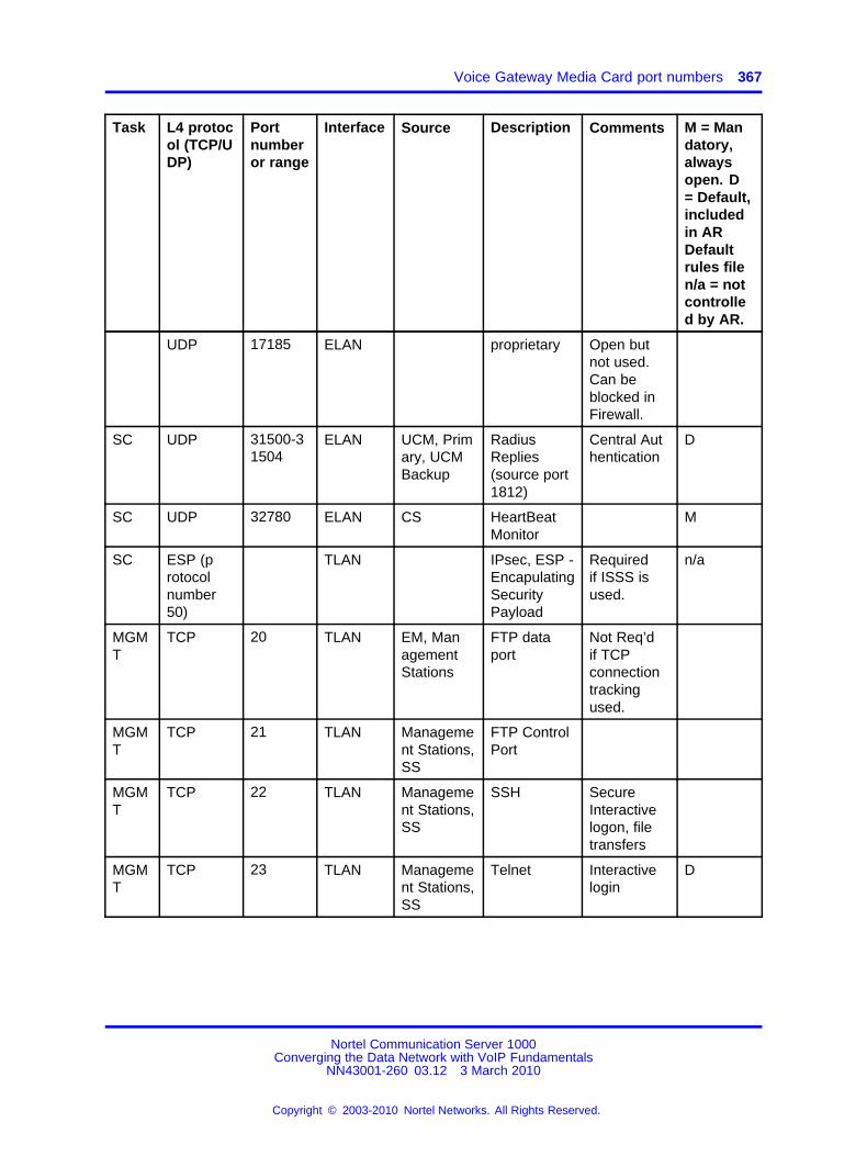
Voice Gateway Media Card port numbers 367
Task L4 protocol (TCP/UDP)
Portnumberor range
Interface Source Description Comments M = Mandatory,alwaysopen. D= Default,includedin ARDefaultrules filen/a = notcontrolled by AR.
UDP 17185 ELAN proprietary Open butnot used.Can beblocked inFirewall.
SC UDP 31500-31504
ELAN UCM, Primary, UCMBackup
RadiusReplies(source port1812)
Central Authentication
D
SC UDP 32780 ELAN CS HeartBeatMonitor
M
SC ESP (protocolnumber50)
TLAN IPsec, ESP -EncapulatingSecurityPayload
Requiredif ISSS isused.
n/a
MGMT
TCP 20 TLAN EM, ManagementStations
FTP dataport
Not Req’dif TCPconnectiontrackingused.
MGMT
TCP 21 TLAN Management Stations,SS
FTP ControlPort
MGMT
TCP 22 TLAN Management Stations,SS
SSH SecureInteractivelogon, filetransfers
MGMT
TCP 23 TLAN Management Stations,SS
Telnet Interactivelogin
D
Nortel Communication Server 1000Converging the Data Network with VoIP Fundamentals
NN43001-260 03.12 3 March 2010
Copyright © 2003-2010 Nortel Networks. All Rights Reserved.
.

368 Port number tables
Task L4 protocol (TCP/UDP)
Portnumberor range
Interface Source Description Comments M = Mandatory,alwaysopen. D= Default,includedin ARDefaultrules filen/a = notcontrolled by AR.
SC TCP 111 TLAN Sunrpc-portmapper
Open butnot used.Can beblocked inFirewall.
D
MGMT
TCP 513 TLAN ECM,SS(EM),SS, CS,management stations
RLOGIN RemoteLogin
TCP 1024-5000
TLAN UCM, EM,Management Stations
Ephemeralports forFTP andTCP
Typicallyhandledusing FTP& TCPconnectiontracking inthe firewalls
M
SC TCP 6666 TLAN ConfigProcess
Open butnot used.Can beblocked inFirewall.
D
SC TCP 32788 TLAN RPC MAIN /RPC GW
preassignedRPC port.Open butnot used.Can beblocked inFirewall.
UDP 68 TLAN bootp Open butnot used.Can beblocked inFirewall.
Nortel Communication Server 1000Converging the Data Network with VoIP Fundamentals
NN43001-260 03.12 3 March 2010
Copyright © 2003-2010 Nortel Networks. All Rights Reserved.
.

Voice Gateway Media Card port numbers 369
Task L4 protocol (TCP/UDP)
Portnumberor range
Interface Source Description Comments M = Mandatory,alwaysopen. D= Default,includedin ARDefaultrules filen/a = notcontrolled by AR.
SC UDP 111 TLAN Sunrpc-portmapper
Open butnot used.Can beblocked inFirewall.
D
MGMT
UDP 162 TLAN SNMP TrapReceiver
Open butnot used.Can beblocked inFirewall.
SC UDP 500 TLAN Any ISSSTarget,source port500
IPSec IKE Requiredif ISSS isused
UDP 514 TLAN Syslog Open on 32port VGMCby not used.Can beblocked inFirewall.
SC UDP 15001 TLAN CS StateChangebroadcasts
Open butnot used.May beblocked infirewall.
M
SC UDP 15010 TLAN CS AFS Open butnot used.May beblockedin firewall.source port15010
M
Nortel Communication Server 1000Converging the Data Network with VoIP Fundamentals
NN43001-260 03.12 3 March 2010
Copyright © 2003-2010 Nortel Networks. All Rights Reserved.
.

370 Port number tables
Task L4 protocol (TCP/UDP)
Portnumberor range
Interface Source Description Comments M = Mandatory,alwaysopen. D= Default,includedin ARDefaultrules filen/a = notcontrolled by AR.
SC UDP 15011 TLAN CS AFS Open butnot used.May beblockedin firewall.source port15011
M
UDP 17185 TLAN proprietary Open butnot used.Can beblocked inFirewall.
SC UDP 31500-31504
TLAN UCM, Primary, UCMBackup
RadiusReplies(source port1812)
Central Authentication
D
VoIPMedia
UDP (RTP, SRTP)
5200-5246
TLAN IP phones,MGCs,VGMCs,voice GWs
RTP, SRTP even numbers-ITGP
n/a
VoIPMedia
UDP (RTP, SRTP)
5200-5262
TLAN IP phones,MGCs,VGMCs,voice GWs
RTP, SRTP even numbers-MediaCard
n/a
VoIPMedia
UDP(RTCP)
5201-5247
TLAN IP phones,MGCs,VGMCs,voice GWs
RTCP odd numbers-ITGP
n/a
VoIPMedia
UDP(RTCP)
5201-5263
TLAN IP phones,MGCs,VGMCs,voice GWs
RTCP odd numbers-MediaCard
n/a
Nortel Communication Server 1000Converging the Data Network with VoIP Fundamentals
NN43001-260 03.12 3 March 2010
Copyright © 2003-2010 Nortel Networks. All Rights Reserved.
.
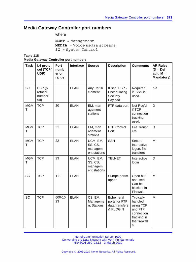
Media Gateway Controller port numbers 371
Media Gateway Controller port numberswhere
MGMT = ManagementMEDIA = Voice media streamsSC = System Control
Table 118Media Gateway Controller port numbers
Task L4 protocol (TCP/UDP)
Portnumber orrange
Interface Source Description Comments AR Rules(D = Default, M =Mandatory)
SC ESP (protocolnumber50)
ELAN Any CS1Kelement
IPsec, ESP -EncapulatingSecurityPayload
Requiredif ISSS isused.
n/a
MGMT
TCP 20 ELAN EM, managementstations
FTP data port Not Req’dif TCPconnectiontrackingused.
D
MGMT
TCP 21 ELAN EM, managementstations
FTP ControlPort
File Transfers
D
MGMT
TCP 22 ELAN UCM, EM,SS, CS,management stations
SSH SecureInteractivelogon, filetransfers
M
MGMT
TCP 23 ELAN UCM, EM,SS, CS,management stations
TELNET Interactivelogin
D
SC TCP 111 ELAN Sunrpc-portmapper
Open butnot used.Can beblocked inFirewall.
M
SC TCP 600-1023
ELAN CS, EM,Management Stations
Ephemeralports for FTPdata transfers& RLOGIN
Typicallyhandledusing TCPand FTPconnectiontracking inthe firewalls
M
Nortel Communication Server 1000Converging the Data Network with VoIP Fundamentals
NN43001-260 03.12 3 March 2010
Copyright © 2003-2010 Nortel Networks. All Rights Reserved.
.

372 Port number tables
Task L4 protocol (TCP/UDP)
Portnumber orrange
Interface Source Description Comments AR Rules(D = Default, M =Mandatory)
SC TCP 1024-5000
ELAN SS (EM),TM, CS,alternateCS, managementstations
Ephemeralports
Typicallyhandledusing TCPconnectiontracking inthe firewalls
M
TCP 2010 ELAN CS CEMUX(PRI/BRID-Channels)
SC TCP 6666 ELAN CS, UCM Config Process
Used forSNMP andNTP configuration propagation.
D
MGMT
TCP 15080 ELAN EM XMSG Used byElementManager
M
SC TCP 32782 ELAN CS CEMUX(PRI/BRID-Channels)
M
SC TCP 32783 ELAN CS CEMUX(PRI/BRID-Channels)
SC TCP 32786 ELAN CS IPMG DBSync
D
SC TCP 32788 ELAN CS RPC MAIN /RPC GW
preassigned RPC port.
M
SC TCP 32789 ELAN CS RPC INSTALL/ RPC GWINSTALL
preassigned RPC port.Applicablefor Co-resand VxWorks
M
SC UDP 111 ELAN CS (activeand anyalternates)
Sunrpc-portmapper
RemoteProcedureCalls
M
MGMT
UDP 161 ELAN TM, ManagementSystems
SNMP query SNMP Management
D
Nortel Communication Server 1000Converging the Data Network with VoIP Fundamentals
NN43001-260 03.12 3 March 2010
Copyright © 2003-2010 Nortel Networks. All Rights Reserved.
.
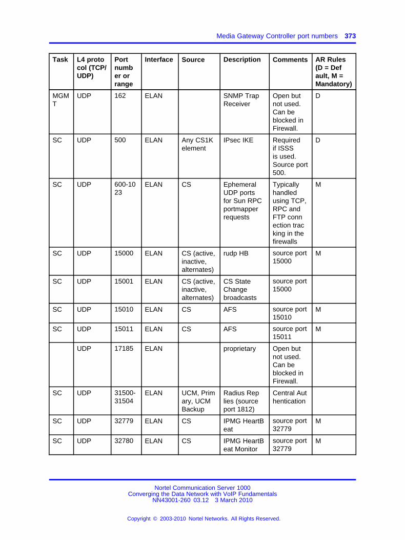
Media Gateway Controller port numbers 373
Task L4 protocol (TCP/UDP)
Portnumber orrange
Interface Source Description Comments AR Rules(D = Default, M =Mandatory)
MGMT
UDP 162 ELAN SNMP TrapReceiver
Open butnot used.Can beblocked inFirewall.
D
SC UDP 500 ELAN Any CS1Kelement
IPsec IKE Requiredif ISSSis used.Source port500.
D
SC UDP 600-1023
ELAN CS EphemeralUDP portsfor Sun RPCportmapperrequests
Typicallyhandledusing TCP,RPC andFTP connection tracking in thefirewalls
M
SC UDP 15000 ELAN CS (active,inactive,alternates)
rudp HB source port15000
M
SC UDP 15001 ELAN CS (active,inactive,alternates)
CS StateChangebroadcasts
source port15000
SC UDP 15010 ELAN CS AFS source port15010
M
SC UDP 15011 ELAN CS AFS source port15011
M
UDP 17185 ELAN proprietary Open butnot used.Can beblocked inFirewall.
SC UDP 31500-31504
ELAN UCM, Primary, UCMBackup
Radius Replies (sourceport 1812)
Central Authentication
SC UDP 32779 ELAN CS IPMG HeartBeat
source port32779
M
SC UDP 32780 ELAN CS IPMG HeartBeat Monitor
source port32779
M
Nortel Communication Server 1000Converging the Data Network with VoIP Fundamentals
NN43001-260 03.12 3 March 2010
Copyright © 2003-2010 Nortel Networks. All Rights Reserved.
.

374 Port number tables
Task L4 protocol (TCP/UDP)
Portnumber orrange
Interface Source Description Comments AR Rules(D = Default, M =Mandatory)
SC ESP (protocolnumber50)
TLAN Any CS1Kelement
IPsec, ESP -EncapulatingSecurityPayload
Requiredif ISSS isused.
n/a
MGMT
TCP 20 TLAN EM, managementstations
FTP data port Not Req’dif TCPconnectiontrackingused.
MGMT
TCP 21 TLAN EM, managementstations
FTP ControlPort
File Transfers
MGMT
TCP 22 TLAN UCM, EM,SS, CS,management stations
SSH SecureInteractivelogon, filetransfers
MGMT
TCP 23 TLAN Management Stations
TELNET RemoteLogin
D
SC TCP 111 TLAN Sunrpc-portmapper
Open butnot used.Can beblocked inFirewall.
MGMT
TCP 513 TLAN UCM, EM,SS, CS,management stations
RLOGIN RemoteLogin
D
SC TCP 600-1023
TLAN Management Stations
Ephemeralports for FTPdata transfers& RLOGIN
Typicallyhandledusing TCPand FTPconnectiontracking inthe firewalls
M
SC TCP 1024-5000
TLAN Management Stations
Ephemeralports
Typicallyhandledusing TCPconnectiontracking inthe firewalls
M
Nortel Communication Server 1000Converging the Data Network with VoIP Fundamentals
NN43001-260 03.12 3 March 2010
Copyright © 2003-2010 Nortel Networks. All Rights Reserved.
.

Media Gateway Controller port numbers 375
Task L4 protocol (TCP/UDP)
Portnumber orrange
Interface Source Description Comments AR Rules(D = Default, M =Mandatory)
SC TCP 6666 TLAN Config Process
Open butnot used.Can beblocked inFirewall.
D
SC TCP 32786 TLAN IPMG DBSync
Open butnot used.Can beblocked inFirewall.
SC TCP 32788 TLAN RPC MAIN /RPC GW
preassigned RPC port.Open butnot used.Can beblocked inFirewall.
SC TCP 32789 TLAN RPC INSTALL/ RPC GWINSTALL
preassigned RPC port.Open butnot used.Can beblocked inFirewall.
SC UDP 111 TLAN Sunrpc-portmapper
Open butnot used.Can beblocked inFirewall.
MGMT
UDP 162 TLAN SNMP TrapReceiver
Open butnot used.Can beblocked inFirewall.
SC UDP 500 TLAN Any CS1Kelement
IPsec IKE Requiredif ISSSis used.Source port500.
D
Nortel Communication Server 1000Converging the Data Network with VoIP Fundamentals
NN43001-260 03.12 3 March 2010
Copyright © 2003-2010 Nortel Networks. All Rights Reserved.
.

376 Port number tables
Task L4 protocol (TCP/UDP)
Portnumber orrange
Interface Source Description Comments AR Rules(D = Default, M =Mandatory)
SC UDP 15001 TLAN CS StateChangebroadcasts
Open butnot used.May beblocked infirewall.
SC UDP 15010 TLAN AFS Open butnot used.May beblockedin firewall.source port15010
M
SC UDP 15011 TLAN AFS Open butnot used.May beblocked infirewall.
M
UDP 17185 TLAN proprietary Open butnot used.Can beblocked inFirewall.
SC UDP 31500-31504
TLAN UCM, Primary, UCMBackup
Radius Replies (sourceport 1812)
Central Authentication
D
SC UDP 32779 TLAN IPMG HeartBeat
Open butnot used.Can beblocked inFirewall.
SC UDP 32780 TLAN IPMG HeartBeat Monitor
Open butnot used.Can beblocked inFirewall.
Media
UDP (RTP, SRTP)
5392-5583(DB1)5200-5391(DB2)
TLANof DSPDaughterboards
IP phones,MGCs,VGMCs,voice GWs
RTCP,RTP (Oddnumbers arefor RTCPand evennumbers arefor RTP)
VoiceMedia
n/a
Nortel Communication Server 1000Converging the Data Network with VoIP Fundamentals
NN43001-260 03.12 3 March 2010
Copyright © 2003-2010 Nortel Networks. All Rights Reserved.
.

Co-resident (Linux) Call Server port numbers 377
Co-resident (Linux) Call Server port numberswhere
BASE = Linux BaseCS = Coresident Call Server
Task L4 protocol(TCP/UDP)
Port numberor range
Interface
Source Description Comments
Base ESP (protocolnumber 50)
ELAN Any CS1Kelement
IPsec, ESP- Encapulating SecurityPayload
Required ifISSS is used.
Base ICMP ELAN UCM, SS,CS
Base TCP 20 ELAN MGC, VGMC, SS, TM,GR CS, mateCS, backupservers,managementstations
FTP dataport
Not Req’d ifTCP connection trackingused.
Base TCP 21 ELAN MGC, VGMC, SS, TM,GR CS, mateCS, backupservers,managementstations
FTP CtrlPort
Insecure FileTransfers
Base TCP 22 ELAN UCM, managementstations, EM
SSH Secure Interactive logon, filetransfers
Base TCP 23 ELAN ManagementSystems,UCM, MGC,VGMC, CS
TELNET Interactivelogon
Base TCP 80 ELAN ManagementStations
http Web Interface
CS TCP 111 ELAN Sunrpc-portmapper
Open but notused. Canbe blocked inFirewall.
Base TCP 443 ELAN ManagementSystems
https Secure WebInterface
Base TCP 513 ELAN SS, Management stations
rlogin Remote Login
Nortel Communication Server 1000Converging the Data Network with VoIP Fundamentals
NN43001-260 03.12 3 March 2010
Copyright © 2003-2010 Nortel Networks. All Rights Reserved.
.

378 Port number tables
Task L4 protocol(TCP/UDP)
Port numberor range
Interface
Source Description Comments
SS TCP 705 Loopback
Internal SS-Subagent
LoopbackInterfaceOnly, can beblocked onELAN/TLANby firewall.
Base TCP 2000 ELAN ManagementStations
Gryphon Web Interface
Base TCP 3306 ELAN Internal MySQL Local Database Access
Base TCP 6666 ELAN CS, SS,VGMC,MGC, UCM
ConfigProcess
Used for SNMP and NTPconfigurationpropagation.
CS TCP 8888 ELAN ContactCenter, CallPilot, MLS,SS
AML 3rd Party CallControl
CS TCP 15000 ELAN MGC, VGMC, SS
pbxLink
CS TCP 15081 ELAN EM Xmsg Server
For CS 1000ElementManager
Base TCP 15086 ELAN Gryphon pcap Control
Base TCP 25100-25200 ELAN MangementStations, MGC, VGMC,SS, BackupServers
FTP DataPorts
Typicallyhandledusing FTPconnectiontracking in thefirewalls
CS TCP 32781 ELAN MGC IPMG SSD
CS TCP 32784 ELAN MGC IPMG TTY
CS TCP 32788 ELAN MGC RPC MAIN /RPC GW
preassignedRPC port.
CS TCP 32789 ELAN MGC RPC INSTALL/RPC GWINSTALL
preassignedRPC port.
Nortel Communication Server 1000Converging the Data Network with VoIP Fundamentals
NN43001-260 03.12 3 March 2010
Copyright © 2003-2010 Nortel Networks. All Rights Reserved.
.

Co-resident (Linux) Call Server port numbers 379
Task L4 protocol(TCP/UDP)
Port numberor range
Interface
Source Description Comments
Base TCP 33700-61000 ELAN UCM, SS,MGC, VGMC, TM,ManagementStations,ContactCenter,CallPilot
Ephemeralports
Typicallyhandled usingTCP and FTPconnectiontracking in thefirewalls
Base UDP 53 TLAN SS DNS
CS UDP 111 ELAN MGC Sunrpc-portmapper
RPC Servicefor MGC
Base UDP 123 ELAN External NTPServer
NTP Time Synchronization.Source port500.
Base UDP 161 ELAN ManagementSystems, TM
SNMPquery
Base UDP 500 ELAN Any CS1Kelement
IPsec IKE Required ifISSS is used.Source port500
Base UDP 514 ELAN Linux Elements
Syslog
CS UDP 1929 ELAN TM DBA CDR/TRF
Used by TM
CS UDP 2058-2185 ELAN TM DBA Data Used by TM
CS UDP 15000 ELAN CS RUDPPBXlinkfrom CS
Base UDP 15010 ELAN SS, MGC,VGMC,inactive CS
AFS Source Port15010
Base UDP 15011 ELAN SS, MGC,VGMC,inactive CS
AFS Source Port15011
CS UDP 31500-31504 ELAN UCM, Primary, UCMBackup
RadiusReplies(source port1812)
CentralAuthentication
CS UDP 32779 ELAN MGC IPMG HeartBeat
source port32779, 32780
Nortel Communication Server 1000Converging the Data Network with VoIP Fundamentals
NN43001-260 03.12 3 March 2010
Copyright © 2003-2010 Nortel Networks. All Rights Reserved.
.

380 Port number tables
Task L4 protocol(TCP/UDP)
Port numberor range
Interface
Source Description Comments
CS UDP 32780 ELAN MGC IPMGHeartBeatMonitor
source port32779
Base UDP 33434-33524 ELAN ANY Traceroute
Base UDP 33600-33699 ELAN UCM, Primary, UCMBackup
RadiusReplies(source port1812)
CentralAuthentication
Base ESP (protocolnumber 50)
TLAN Any CS1Kelement
IPsec, ESP- Encapulating SecurityPayload
Required ifISSS is used.
Base ICMP TLAN UCM, SS,CS
Base TCP 20 TLAN backupservers,managementstations
FTP dataport
Not Req’d ifTCP connection trackingused.
Base TCP 21 TLAN backupservers,managementstations
FTP CtrlPort
Insecure FileTransfers
Base TCP 22 TLAN UCM, managementstations
SSH Secure Interactive logon, filetransfers
Base TCP 23 TLAN UCM, managementstations
TELNET Interactivelogon
Base TCP 80 TLAN ManagementStations
http Web Interface
Base TCP 443 TLAN ManagementStations
https Secure WebInterface
Base TCP 513 TLAN RemoteManagementSystems
rlogin Interactivelogon (whenrlogin isenabled)
Base TCP 705 Loopback
Internal SS-Subagent
LoopbackInterfaceOnly, can beblocked onELAN/TLANby firewall.
Nortel Communication Server 1000Converging the Data Network with VoIP Fundamentals
NN43001-260 03.12 3 March 2010
Copyright © 2003-2010 Nortel Networks. All Rights Reserved.
.

Co-resident (Linux) Call Server port numbers 381
Task L4 protocol(TCP/UDP)
Port numberor range
Interface
Source Description Comments
Base TCP 2000 TLAN ManagementStations
Gryphon Web Interface
Base TCP 3306 TLAN Internal MySQL Local Database Access
Base TCP 6666 TLAN CS, SS,VGMC,MGC, UCM
ConfigProcess
Typically usesELAN only
Base TCP 15086 TLAN Gryphon pcap Control
Base TCP 25100-25200 TLAN backupservers,managementstations
FTP DataPorts
Typicallyhandledusing FTPconnectiontracking in thefirewalls
Base UDP 31500-31504 TLAN UCM, Primary, UCMBackup
RadiusReplies(source port1812)
CentralAuthentication
Base TCP 33700-61000 TLAN UCM, ManagementStations,BackupServers
Ephemeralports
Typicallyhandled usingTCP and FTPconnectiontracking in thefirewalls
Base UDP 53 TLAN SS DNS
Base UDP 123 TLAN External NTPServer
NTP, sourceport 123
Time Synchronization
Base UDP 161 TLAN TM, SNMPManagementSystems
SNMPquery
It is recommended to useELAN
Base UDP 500 TLAN Any CS1Kelement
IPsec IKE Required ifISSS is used.Source port500
Base UDP 514 TLAN Linux Elements
Syslog
Base UDP 15010 TLAN SS, MGC,VGMC,CS
AFS
Nortel Communication Server 1000Converging the Data Network with VoIP Fundamentals
NN43001-260 03.12 3 March 2010
Copyright © 2003-2010 Nortel Networks. All Rights Reserved.
.

382 Port number tables
Task L4 protocol(TCP/UDP)
Port numberor range
Interface
Source Description Comments
Base UDP 15011 TLAN SS, MGC,VGMC,CS
AFS
Base UDP 33600-33699 TLAN UCM, Primary, UCMBackup
RadiusReplies(source port1812)
CentralAuthentication
Signaling Server port numbers
Note: Various combinations of the following Linux applications can beconfigured in co-resident configurations. The resulting port usage fora "co-resident" server is the superset of the ports for the constituentelements.
where
BASE = Linux BaseVTRK = IP Virtual TrunksTPS = UNIStim Terminal Proxy Server
Table 119Signaling Server port numbers
Task L4 protocol(TCP/UDP)
Port number orrange
Interface
Source Description Comments
Base ESP (protocolnumber 50)
ELAN Any CS1Kelement
IPsec, ESP -EncapsulatingSecurityPayload
Required ifISSS is used.
Base ICMP ELAN UCM, SS,CS
Base TCP 20 ELAN UCM, VGMCs, EM, managementstations
FTP data port Not Req’d ifTCP connectiontracking used.
Base TCP 21 ELAN UCM, VGMCs, EM, managementstations
FTP Ctrl Port Insecure FileTransfers
Base TCP 22 ELAN Management Stations,UCM
SSH Secure Interactive logon
Nortel Communication Server 1000Converging the Data Network with VoIP Fundamentals
NN43001-260 03.12 3 March 2010
Copyright © 2003-2010 Nortel Networks. All Rights Reserved.
.

Signaling Server port numbers 383
Task L4 protocol(TCP/UDP)
Port number orrange
Interface
Source Description Comments
Base TCP 23 ELAN Management Stations,UCM
TELNET Interactivelogon
Base TCP 80 ELAN UCM, managementstations
http Web Interface
Base TCP 443 ELAN Management Stations
https Secure WebInterface
Base TCP 705 ELAN Internal SS-Subagent LoopbackInterface Only
Base TCP 2000 ELAN Management Stations
Gryphon Web Interface
Base TCP 3306 ELAN Internal MySQL Local DatabaseAccess
Base TCP 6666 ELAN CS Config Process Used for SNMPand NTPconfigurationpropagation.
Base TCP 15080 ELAN EM xmsg server Used by Element Manager
Base TCP 15086 ELAN Gryphon PCAP Control
Base TCP 25100-25200
ELAN VGMC, CS,SS, ManagementStations
FTP Data Ports Typicallyhandled usingFTP connectiontracking in thefirewalls
Base TCP 33700-61000
ELAN ANY Ephemeralports
Typicallyhandled usingTCP and FTPconnectiontracking in thefirewalls
Base UDP 53 ELAN DNS
Base UDP 67 ELAN VGMC bootp server VGMC boot
Base UDP 123 ELAN ExternalNTP Server
NTP, sourceport 123
Time Synchronization
Base UDP 161 ELAN TM, SNMPManagement Systems
SNMP query
Nortel Communication Server 1000Converging the Data Network with VoIP Fundamentals
NN43001-260 03.12 3 March 2010
Copyright © 2003-2010 Nortel Networks. All Rights Reserved.
.
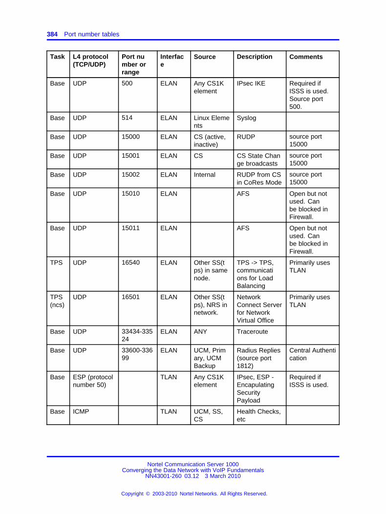
384 Port number tables
Task L4 protocol(TCP/UDP)
Port number orrange
Interface
Source Description Comments
Base UDP 500 ELAN Any CS1Kelement
IPsec IKE Required ifISSS is used.Source port500.
Base UDP 514 ELAN Linux Elements
Syslog
Base UDP 15000 ELAN CS (active,inactive)
RUDP source port15000
Base UDP 15001 ELAN CS CS State Change broadcasts
source port15000
Base UDP 15002 ELAN Internal RUDP from CSin CoRes Mode
source port15000
Base UDP 15010 ELAN AFS Open but notused. Canbe blocked inFirewall.
Base UDP 15011 ELAN AFS Open but notused. Canbe blocked inFirewall.
TPS UDP 16540 ELAN Other SS(tps) in samenode.
TPS -> TPS,communications for LoadBalancing
Primarily usesTLAN
TPS(ncs)
UDP 16501 ELAN Other SS(tps), NRS innetwork.
NetworkConnect Serverfor NetworkVirtual Office
Primarily usesTLAN
Base UDP 33434-33524
ELAN ANY Traceroute
Base UDP 33600-33699
ELAN UCM, Primary, UCMBackup
Radius Replies(source port1812)
Central Authentication
Base ESP (protocolnumber 50)
TLAN Any CS1Kelement
IPsec, ESP -EncapulatingSecurityPayload
Required ifISSS is used.
Base ICMP TLAN UCM, SS,CS
Health Checks,etc
Nortel Communication Server 1000Converging the Data Network with VoIP Fundamentals
NN43001-260 03.12 3 March 2010
Copyright © 2003-2010 Nortel Networks. All Rights Reserved.
.

Signaling Server port numbers 385
Task L4 protocol(TCP/UDP)
Port number orrange
Interface
Source Description Comments
TCP 20 TLAN UCM, VGMCs, EM, managementstations
FTP data port Not Req’d ifTCP connectiontracking used.
Base TCP 21 TLAN UCM, VGMCs, EM, managementstations
FTP Ctrl Port Insecure FileTransfers
Base TCP 22 TLAN Management Stations,UCM
SSH Secure Interactive logon
Base TCP 23 TLAN Management Stations,UCM
TELNET Interactivelogon
Base TCP 80 TLAN,TLAN-nodeIP
UCM, managementstations
http Web Interface
Base TCP 443 TLAN,TLAN-nodeIP
Management Stations
https Secure WebInterface
Base TCP 705 TLAN Internal SS-Subagent LoopbackInterface Only
VTRK
TCP 1718 TLAN(nodeIP)
H.323 Not Used.
VTRK
TCP 1719 TLAN(nodeIP)
SS(vtrk),NRS (gk),other H.323devices
H.323/H.245 H.323 Vtrksignalingbetween GW’s.
VTRK
TCP 1720 TLAN(nodeIP)
SS(vtrk),other H.323devices
H.323/H.245 H.323 Vtrksignalingbetween GW’s.
Base TCP 2000 TLAN,TLAN(nodeIP)
Management Stations
Gryphon
Base TCP 3306 TLAN Internal MySQL Local DatabaseAccess
VTRK
TCP 5060 TLAN(nodeIP)
SS(vtrk),NRS, otherSIP devices
SIP SIP Signaling
Nortel Communication Server 1000Converging the Data Network with VoIP Fundamentals
NN43001-260 03.12 3 March 2010
Copyright © 2003-2010 Nortel Networks. All Rights Reserved.
.

386 Port number tables
Task L4 protocol(TCP/UDP)
Port number orrange
Interface
Source Description Comments
VTRK
TCP 5061 TLAN(nodeIP)
SS(vtrk),NRS, otherSIP devices
SIP/TLS Secure SIP(TLS) Signaling
Base TCP 6666 TLAN CS Config Process Used for SNMPand NTPconfigurationpropagation.
VTRK (amlfe)
TCP 8888 TLAN ContactCenter, CallPilot, MLS
AML 3rd Party CallControl
Base TCP 15086 TLAN Gryphon pcap Control
Base TCP 15080 TLAN EM xmsg server Used by Element Manager
Base TCP 25100-25200
TLAN Management Stations,UCM
FTP Data Ports Typicallyhandled usingFTP connectiontracking in thefirewalls
Base TCP 33700-61000
TLAN UCM, managementstations,EM, NRS,SS(GK),SS(vtrk),Other SIP orH.323 GW
Ephemeralports
Typicallyhandled usingTCP & FTPconnectiontracking in thefirewalls
VTRK
TCP 40000-42400
TLAN(nodeIP)
SS (vtrk),other H.323devices
H.245 Signaling
Base UDP 53 TLAN DNS
TPS UDP 69 TLAN IP Phones tftp FirmwareDownload for IPPhones (Req’dfor Phase 1phones)
Base UDP 123 TLAN ExternalNTP Server
NTP, sourceport 123
Time Synchronization
Base UDP 161 TLAN TM, SNMPManagement Systems
SNMP query It is recommended to use ELAN
Nortel Communication Server 1000Converging the Data Network with VoIP Fundamentals
NN43001-260 03.12 3 March 2010
Copyright © 2003-2010 Nortel Networks. All Rights Reserved.
.

Signaling Server port numbers 387
Task L4 protocol(TCP/UDP)
Port number orrange
Interface
Source Description Comments
Base UDP 500 TLAN Any ISSSTarget
IPsec IKE,source port 500
Required ifISSS is used.
Base UDP 514 TLAN Linux Elements
Syslog
VTRK
UDP 1718 TLAN(nodeIP)
H.323 Not Used.
VTRK
UDP 1719 TLAN(nodeIP)
SS(vtrk),NRS (gk),other H.323devices
H.323 RAS Signalingbetween VTRKand NRS (gk)
VTRK
UDP 1720 TLAN(nodeIP)
SS(vtrk),other H.323devices
H.323 H.323 Vtrksignalingbetween GW’s.
TPS(csv)
UDP 4100 TLAN(nodeIP)
UNISTIM IPPhones
UNIStim ConnectionServer
TPS(csv)
UDP 4101 TLAN(nodeIP)
UNISTIM IPPhones
UNIStim /DTLS
ConnectionServer (secure)
VTRK
UDP 5060 TLAN(nodeIP)
SS(vtrk),NRS (sps)
SIP (sourceport 5060)
SIP Signaling
TPS UDP 5100 TLAN IP Phones UNIStim Terminal ProxyServer
TPS UDP 5101 TLAN IP Phones UNIStim /DTLS
Terminal ProxyServer (secure)
TPS UDP 5105 TLAN Phase 2and later IPPhones
UFTP FirmwareDownloadUNISTM IPPhones
TPS UDP 7300 TLAN IP Phones UNIStim TPS LoadBalancing
TPS UDP 7301 TLAN IP Phones UNIStim /DTLS
TPS LoadBalancing(secure)
TPS UDP 10000 TLAN IP Phones Echo Server NAT Discovery
Base UDP 15010 TLAN AFS Open but notused. Canbe blocked inFirewall.
Nortel Communication Server 1000Converging the Data Network with VoIP Fundamentals
NN43001-260 03.12 3 March 2010
Copyright © 2003-2010 Nortel Networks. All Rights Reserved.
.

388 Port number tables
Task L4 protocol(TCP/UDP)
Port number orrange
Interface
Source Description Comments
Base UDP 15011 TLAN AFS Open but notused. Canbe blocked inFirewall.
TPS(ncs)
UDP 16501 TLAN Other SS(tps), NRS innetwork.
NetworkConnect Server
Network VirtualOffice
TPS(ncs)
UDP 16502 TLAN NRS (ncs)<-> TPS(ncs)
NetworkConnect Server
NCS - CS2100
TPS UDP 16540 TLAN Other SS(tps) insame node.
TPS -> TPS(TPS)
TPS to TPScommunications for LoadBalancing
Base UDP 16550 TLAN Other SS innode
SS <-> SS Leader/FollowerElection
Base UDP 33434-33524
ELAN ANY Traceroute
Base UDP 33600-33699
TLAN UCM, Primary, UCMBackup
Radius Replies(source port1812)
Central Authentication
SIP Lines Gateway Port Numbers
Note: Various combinations of the following Linux applications can beconfigured in co-resident configurations. The resulting port usage fora "co-resident" server is the superset of the ports for the constituentelements.
where
Base = Linux BaseSIPL = SIP Lines
Table 120SIP Lines Gateway Port Numbers
Task L4 protocol(TCP/UDP)
Port number or range
Interface Source Description Comments
Nortel Communication Server 1000Converging the Data Network with VoIP Fundamentals
NN43001-260 03.12 3 March 2010
Copyright © 2003-2010 Nortel Networks. All Rights Reserved.
.

SIP Lines Gateway Port Numbers 389
Task L4 protocol(TCP/UDP)
Port number or range
Interface Source Description Comments
Base ESP (protocol number50)
ELAN Any CS1Kelement
IPsec, ESP -EncapulatingSecurityPayload
Required ifISSS is used.
Base ICMP ELAN UCM, SS, CS
Base TCP 20 ELAN UCM, EM,managementstations
FTP data port Not Req’d ifTCP connection trackingused.
Base TCP 21 ELAN UCM, EM,managementstations
FTP Ctrl Port Insecure FileTransfers
Base TCP 22 ELAN ManagementStations, UCM
SSH Secure Interactive logon
Base TCP 23 ELAN ManagementStations, UCM
TELNET Interactivelogon
Base TCP 80 ELAN UCM, management stations
http Web Interface
Base TCP 443 ELAN ManagementStations
https Secure WebInterface
Base TCP 705 ELAN Internal SS-Subagent LoopbackInterface Only
Base TCP 2000 ELAN ManagementStations
Gryphon Web Interface
Base TCP 3306 ELAN Internal MySQL Local Database Access
Base TCP 6666 ELAN CS Config Process Used for SNMP and NTPconfigurationpropagation.
Base UDP 15010 ELAN AFS Open but notused. Canbe blocked inFirewall.
Base UDP 15011 ELAN AFS Open but notused. Canbe blocked inFirewall.
Base TCP 15080 ELAN EM xmsg server Used byElementManager
Nortel Communication Server 1000Converging the Data Network with VoIP Fundamentals
NN43001-260 03.12 3 March 2010
Copyright © 2003-2010 Nortel Networks. All Rights Reserved.
.

390 Port number tables
Task L4 protocol(TCP/UDP)
Port number or range
Interface Source Description Comments
Base TCP 15086 ELAN Gryphon PCAP Control
Base TCP 25100-25200
ELAN CS, SS,ManagementStations
FTP Data Ports Typicallyhandledusing FTPconnectiontracking in thefirewalls
Base TCP 33700-61000
ELAN CS, SS,EM, UCM,ManagementStations
Ephemeral ports Typicallyhandled usingTCP and FTPconnectiontracking in thefirewalls
Base UDP 53 ELAN DNS
Base UDP 67 ELAN bootp server Open but notused. Canbe blocked inFirewall.
Base UDP 123 ELAN External NTPServer
NTP, sourceport 123
Time Synchronization
Base UDP 161 ELAN TM, SNMPManagementSystems
SNMP query
Base UDP 500 ELAN Any CS1Kelement
IPsec IKE Required ifISSS is used.Source port500.
Base UDP 514 ELAN Linux Elements
Syslog
Base UDP 15000 ELAN CS (active,inactive,alternatives)
RUDP source port15000
Base UDP 15001 ELAN CS (active,inactive,alternates)
CS State Change broadcasts
source port15000
Base UDP 15002 ELAN Internal RUDP from CSin CoRes Mode
source port15000
Base UDP 15010 ELAN AFS Open but notused. Canbe blocked inFirewall.
Nortel Communication Server 1000Converging the Data Network with VoIP Fundamentals
NN43001-260 03.12 3 March 2010
Copyright © 2003-2010 Nortel Networks. All Rights Reserved.
.

SIP Lines Gateway Port Numbers 391
Task L4 protocol(TCP/UDP)
Port number or range
Interface Source Description Comments
Base UDP 15011 ELAN AFS Open but notused. Canbe blocked inFirewall.
Base UDP 33434-33524
ELAN ANY Traceroute
Base UDP 33600-33699
ELAN UCM, Primary, UCMBackup
Radius Replies(source port1812)
CentralAuthentication
Base ESP (protocol number50)
TLAN Any CS1Kelement
IPsec, ESP -EncapulatingSecurityPayload
Required ifISSS is used.
Base ICMP TLAN UCM, SS, CS Health Checks,etc
Base TCP 20 TLAN UCM, EM,managementstations
FTP data port Not Req’d ifTCP connection trackingused.
Base TCP 21 TLAN UCM, EM,managementstations
FTP Ctrl Port Insecure FileTransfers
Base TCP 22 TLAN ManagementStations, UCM
SSH Secure Interactive logon
Base TCP 23 TLAN ManagementStations, UCM
TELNET Interactivelogon
Base TCP 80 TLAN UCM, management stations
http Web Interface
Base TCP 443 TLAN ManagementStations
https Secure WebInterface
Base TCP 705 TLAN Internal SS-Subagent LoopbackInterface Only
Base TCP 2000 TLAN ManagementStations
Gryphon
Base TCP 3306 TLAN Internal MySQL Local Database Access
SIPL TCP 5070 TLAN SIP Phones SIP SIP Signalingwith SIPPhones.
Nortel Communication Server 1000Converging the Data Network with VoIP Fundamentals
NN43001-260 03.12 3 March 2010
Copyright © 2003-2010 Nortel Networks. All Rights Reserved.
.

392 Port number tables
Task L4 protocol(TCP/UDP)
Port number or range
Interface Source Description Comments
SIPL TCP 5071 TLAN SIP Phones SIP/TLS Secure SIPSignaling withSIP Phones.
Base TCP 6666 TLAN CS Config Process Used for SNMP and NTPconfigurationpropagation.
Base TCP 15086 TLAN Gryphon pcap Control
Base TCP 15080 TLAN EM xmsg server Used byElementManager
Base TCP 25100-25200
TLAN ManagementStations,UCM, EM
FTP Data Ports Typicallyhandledusing FTPconnectiontracking in thefirewalls
Base TCP 33700-61000
TLAN UCM, managementstations, EM,SIP Phones
Ephemeral ports Typicallyhandled usingTCP & FTPconnectiontracking in thefirewalls
Base UDP 53 TLAN DNS
Base UDP 123 TLAN External NTPServer
NTP, sourceport 123
Time Synchronization
Base UDP 161 TLAN TM, SNMPManagementSystems
SNMP query It is recommended to useELAN
Base UDP 500 TLAN Any ISSSTarget
IPsec IKE,source port 500
Required ifISSS is used.
Base UDP 514 TLAN Linux Elements
Syslog
SIPL UDP 5070 TLAN SIP Phones SIP SIP Signalingwith SIPPhones.
Base UDP 15010 TLAN AFS Open but notused. Canbe blocked inFirewall.
Nortel Communication Server 1000Converging the Data Network with VoIP Fundamentals
NN43001-260 03.12 3 March 2010
Copyright © 2003-2010 Nortel Networks. All Rights Reserved.
.

Element Manager Port Numbers 393
Task L4 protocol(TCP/UDP)
Port number or range
Interface Source Description Comments
Base UDP 15011 TLAN AFS Open but notused. Canbe blocked inFirewall.
Base UDP 16550 TLAN Other SS innode
SS <-> SS Leader/Follower Election
Base UDP 33434-33524
ELAN ANY Traceroute
Base UDP 33600-33699
TLAN UCM, Primary, UCMBackup
Radius Replies(source port1812)
CentralAuthentication
Element Manager Port Numbers
Note: Various combinations of the following Linux applications can beconfigured in co-resident configurations. The resulting port usage fora "co-resident" server is the superset of the ports for the constituentelements.
where
BASE = Linux BaseEM = Element Manager
Table 121Element Manager Port Numbers
Task L4 protocol(TCP/UDP)
Port number orrange
Interface Source Description Comments
Base ESP (protocolnumber 50)
ELAN Any CS1Kelement
IPsec, ESP -EncapsulatingSecurityPayload
Requiredif ISSS isused.
Base ICMP ELAN UCM, SS, CS
Base TCP 20 ELAN UCM, VGMCs, EM,managementstations
FTP data port Not Req’dif TCPconnectiontrackingused.
Nortel Communication Server 1000Converging the Data Network with VoIP Fundamentals
NN43001-260 03.12 3 March 2010
Copyright © 2003-2010 Nortel Networks. All Rights Reserved.
.

394 Port number tables
Task L4 protocol(TCP/UDP)
Port number orrange
Interface Source Description Comments
Base TCP 21 ELAN UCM, VGMCs, EM,managementstations
FTP Ctrl Port Insecure File Transfers
Base TCP 22 ELAN ManagementStations,UCM
SSH SecureInteractivelogon
Base TCP 23 ELAN ManagementStations,UCM
TELNET Interactivelogon
Base TCP 80 ELAN UCM, managementstations
http Web Interface
Base TCP 443 ELAN ManagementStations
https Secure WebInterface
Base TCP 705 ELAN Internal SS-Subagent LoopbackInterfaceOnly
Base TCP 2000 ELAN ManagementStations
Gryphon Web Interface
Base TCP 3306 ELAN Internal MySQL Local Database Access
EM TCP 4789 ELAN ManagementStations
EM VirtualTerminal Javaapp to EM
Base TCP 6666 ELAN CS Config Process
Used forSNMP andNTP configurationpropagation.
Base TCP 15086 ELAN Gryphon PCAPControl
Base TCP 25100-25200
ELAN VGMC,CS, SS,ManagementStations
FTP DataPorts
Typicallyhandledusing FTPconnectiontracking inthe firewalls
Nortel Communication Server 1000Converging the Data Network with VoIP Fundamentals
NN43001-260 03.12 3 March 2010
Copyright © 2003-2010 Nortel Networks. All Rights Reserved.
.

Element Manager Port Numbers 395
Task L4 protocol(TCP/UDP)
Port number orrange
Interface Source Description Comments
Base TCP 33700-61000
ELAN ANY Ephemeralports
Typicallyhandledusing TCPand FTPconnectiontracking inthe firewalls
Base UDP 53 ELAN DNS
Base UDP 67 ELAN VGMC bootp server VGMC boot
Base UDP 123 ELAN External NTPServer
NTP, sourceport 123
Time Synchronization
Base UDP 161 ELAN TM, SNMPManagementSystems
SNMP query
EM UDP 162 ELAN CS SNMP Traps BCC
Base UDP 500 ELAN Any CS1Kelement
IPsec IKE Requiredif ISSSis used.Source port500.
Base UDP 514 ELAN Linux Elements
Syslog
Base UDP 15010 ELAN AFS Open butnot used.Can beblocked inFirewall.
Base UDP 15011 ELAN AFS Open butnot used.Can beblocked inFirewall.
Base UDP 33434-33524
ELAN ANY Traceroute
Base UDP 33600-33699
ELAN UCM, Primary, UCMBackup
Radius Replies (source port1812)
Central Authentication
Base ESP (protocolnumber 50)
TLAN Any CS1Kelement
IPsec, ESP -EncapulatingSecurityPayload
Requiredif ISSS isused.
Nortel Communication Server 1000Converging the Data Network with VoIP Fundamentals
NN43001-260 03.12 3 March 2010
Copyright © 2003-2010 Nortel Networks. All Rights Reserved.
.

396 Port number tables
Task L4 protocol(TCP/UDP)
Port number orrange
Interface Source Description Comments
Base ICMP TLAN UCM, SS, CS Health Checks, etc
TCP 20 TLAN UCM, VGMCs, EM,managementstations
FTP data port Not Req’dif TCPconnectiontrackingused.
Base TCP 21 TLAN UCM, VGMCs, EM,managementstations
FTP Ctrl Port Insecure File Transfers
Base TCP 22 TLAN ManagementStations,UCM
SSH SecureInteractivelogon
Base TCP 23 TLAN ManagementStations,UCM
TELNET Interactivelogon
Base TCP 80 TLAN, TLAN-nodeIP
UCM, managementstations
http Web Interface
Base TCP 443 TLAN, TLAN-nodeIP
ManagementStations
https Secure WebInterface
Base TCP 705 TLAN Internal SS-Subagent LoopbackInterfaceOnly
Base TCP 2000 TLAN, TLAN(nodeIP)
ManagementStations
Gryphon
Base TCP 3306 TLAN Internal MySQL Local Database Access
EM TCP 4789 TLAN ManagementStations
EM VirtualTerminal Javaapp to EM
Base TCP 6666 TLAN CS Config Process
Used forSNMP andNTP configurationpropagation.
Base TCP 15086 TLAN Gryphon pcap Control
Nortel Communication Server 1000Converging the Data Network with VoIP Fundamentals
NN43001-260 03.12 3 March 2010
Copyright © 2003-2010 Nortel Networks. All Rights Reserved.
.

Element Manager Port Numbers 397
Task L4 protocol(TCP/UDP)
Port number orrange
Interface Source Description Comments
Base TCP 25100-25200
TLAN ManagementStations,UCM
FTP DataPorts
Typicallyhandledusing FTPconnectiontracking inthe firewalls
Base TCP 33700-61000
TLAN UCM, managementstations,EM, NRS,SS(GK),SS(vtrk),Other SIP orH.323 GW
Ephemeralports
Typicallyhandledusing TCP& FTPconnectiontracking inthe firewalls
Base UDP 53 TLAN DNS
Base UDP 123 TLAN External NTPServer
NTP, sourceport 123
Time Synchronization
Base UDP 161 TLAN TM, SNMPManagementSystems
SNMP query It is recommended touse ELAN
EM UDP 162 TLAN SNMP Traps Open butnot used.Can beblocked inFirewall.
Base UDP 500 TLAN Any ISSSTarget
IPsec IKE,source port500
Requiredif ISSS isused.
Base UDP 514 TLAN Linux Elements
Syslog
Base UDP 15010 TLAN AFS Open butnot used.Can beblocked inFirewall.
Nortel Communication Server 1000Converging the Data Network with VoIP Fundamentals
NN43001-260 03.12 3 March 2010
Copyright © 2003-2010 Nortel Networks. All Rights Reserved.
.

398 Port number tables
Task L4 protocol(TCP/UDP)
Port number orrange
Interface Source Description Comments
Base UDP 15011 TLAN AFS Open butnot used.Can beblocked inFirewall.
Base UDP 33600-33699
TLAN UCM Radius Central Authentication.(source port1812)
Network Routing Service Port Numbers
Note: Various combinations of the following Linux applications can beconfigured in co-resident configurations. The resulting port usage fora "co-resident" server is the superset of the ports for the constituentelements.
where
BASE = Linux BaseNRS(GK) = H.323 GatekeeperNRS(SIP) = SIP Proxy Server or SIP Redirect ServerNRS (NCS) = Network Connect Server
Table 122Network Routing Service Port Numbers
Task L4 protocol (TCP/UDP)
Port number or range
Interface Source Description Comments
Base ICMP ELAN UCM, NRS,SS
Health Checkbetween NRSprimary/backup, etc
Base TCP 20 ELAN ManagementStations,UCM, NRS,4.x/5.xfailsafe NRS
FTP data port Not Req’d ifTCP connection trackingused.
Base TCP 21 ELAN ManagementStations
FTP Ctrl Port Insecure FileTransfers
Nortel Communication Server 1000Converging the Data Network with VoIP Fundamentals
NN43001-260 03.12 3 March 2010
Copyright © 2003-2010 Nortel Networks. All Rights Reserved.
.

Network Routing Service Port Numbers 399
Task L4 protocol (TCP/UDP)
Port number or range
Interface Source Description Comments
Base TCP 22 ELAN ManagementStations,UCM, NRS
SSH / sFTP SecureInteractivelogon & FileTransfers
Base TCP 23 ELAN ManagementStations,UCM
TELNET InsecureInteractivelogon
Base TCP 80 ELAN ManagementStations
http Web Interface
Base TCP 443 ELAN ManagementStations
htps Web Interface
Base TCP 2000 ELAN ManagementStations
Gryphon Web Interface
Base TCP 3306 ELAN NRS <->NRS
MySQL DatabaseAccess,typically usesTLAN
NRS(sip)
TCP 5060 ELAN SS(vtrk),NRS, otherSIP devices
SIP SIP Signaling
NRS(sip)
TCP 5061 ELAN SS(vtrk),NRS, otherSIP devices
SIP/TLS SecureSIP (TLS)Signaling
Base TCP 6666 ELAN UCM Config Process
Used for SNMP and NTPconfigurationpropagation.
Base TCP 15086 ELAN Gryphon pcap Control
Base TCP 25100-25200
ELAN 4.x/5.x Failsafe NRS,ManagementStations
FTP DataPorts
Typicallyhandledusing FTPconnectiontracking inthe firewalls
Base TCP 33700-61000
ELAN Backup Servers, NRS,FailsafeNRS, etc
Ephemeralports
Typicallyhandledusing TCPand FTPconnectiontracking inthe firewalls
Nortel Communication Server 1000Converging the Data Network with VoIP Fundamentals
NN43001-260 03.12 3 March 2010
Copyright © 2003-2010 Nortel Networks. All Rights Reserved.
.

400 Port number tables
Task L4 protocol (TCP/UDP)
Port number or range
Interface Source Description Comments
Base UDP 53 ELAN DNS
Base UDP 123 ELAN External NTPServer
NTP, sourceport 123
Time Synchronization
Base UDP 161 ELAN TM, SNMPManagementSystems
SNMP query
Base UDP 514 ELAN Linux Elements
Syslog
NRS(gk)
UDP 1719 ELAN SS (vtrk),NRS (gk)
H.323 - RASSignalingbetweenVtrk GW andGK/NRS
Typicallynot used onELAN.
NRS(sip)
UDP 5060 ELAN SS(vtrk),NRS, otherSIP devices
SIP SIP Signaling
Base UDP 15010 ELAN AFS Open but notused. Canbe blocked inFirewall.
Base UDP 15011 ELAN AFS Open but notused. Canbe blocked inFirewall.
NRS(ncs)
UDP 16500 ELAN SS(tps) NetworkConnectServer forNetworkVirtual Office
Primarilyuses TLAN
NRS(ncs)
UDP 16501 ELAN SS(tps) NetworkConnectServer forNetworkVirtual Office
Primarilyuses TLAN
Base UDP 33434-33524
ELAN ANY Traceroute
Base UDP 33600-33699
ELAN UCM, Primary, UCMBackup
Radius Replies (source port1812)
Central Authentication
Nortel Communication Server 1000Converging the Data Network with VoIP Fundamentals
NN43001-260 03.12 3 March 2010
Copyright © 2003-2010 Nortel Networks. All Rights Reserved.
.
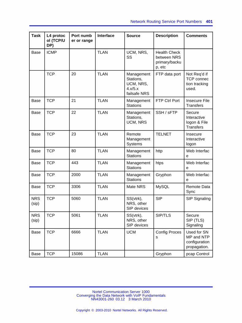
Network Routing Service Port Numbers 401
Task L4 protocol (TCP/UDP)
Port number or range
Interface Source Description Comments
Base ICMP TLAN UCM, NRS,SS
Health Checkbetween NRSprimary/backup, etc
TCP 20 TLAN ManagementStations,UCM, NRS,4.x/5.xfailsafe NRS
FTP data port Not Req’d ifTCP connection trackingused.
Base TCP 21 TLAN ManagementStations
FTP Ctrl Port Insecure FileTransfers
Base TCP 22 TLAN ManagementStations,UCM, NRS
SSH / sFTP SecureInteractivelogon & FileTransfers
Base TCP 23 TLAN RemoteManagementSystems
TELNET InsecureInteractivelogon
Base TCP 80 TLAN ManagementStations
http Web Interface
Base TCP 443 TLAN ManagementStations
htps Web Interface
Base TCP 2000 TLAN ManagementStations
Gryphon Web Interface
Base TCP 3306 TLAN Mate NRS MySQL Remote DataSync
NRS(sip)
TCP 5060 TLAN SS(vtrk),NRS, otherSIP devices
SIP SIP Signaling
NRS(sip)
TCP 5061 TLAN SS(vtrk),NRS, otherSIP devices
SIP/TLS SecureSIP (TLS)Signaling
Base TCP 6666 TLAN UCM Config Process
Used for SNMP and NTPconfigurationpropagation.
Base TCP 15086 TLAN Gryphon pcap Control
Nortel Communication Server 1000Converging the Data Network with VoIP Fundamentals
NN43001-260 03.12 3 March 2010
Copyright © 2003-2010 Nortel Networks. All Rights Reserved.
.

402 Port number tables
Task L4 protocol (TCP/UDP)
Port number or range
Interface Source Description Comments
Base TCP 25100-25200
TLAN 4.x/5.x Failsafe NRS,ManagementStations
FTP DataPorts
Typicallyhandledusing FTPconnectiontracking inthe firewalls
Base TCP 33700-61000
TLAN Backup Servers, NRS,FailsafeNRS, etc
Ephemeralports
Typically handled usingTCP & FTPconnectiontracking inthe firewalls
Base UDP 53 TLAN DNS
Base UDP 123 TLAN External NTPServer
NTP, sourceport 123
Time Synchronization
Base UDP 161 TLAN TM, SNMPManagementSystems
SNMP query It is recommended to useELAN
Base UDP 514 TLAN Linux Elements
Syslog
NRS(gk)
UDP 1719 TLAN SS(vtrk),NRS (gk),other H.323devices
H.323 RAS Signaling betweenVTRK andNRS (gk)
NRS(sip)
UDP 5060 TLAN SS(vtrk),NRS, otherSIP devices
SIP (sourceport 5060)
SIP Signaling
Base UDP 15010 TLAN AFS Open but notused. Canbe blocked inFirewall.
Base UDP 15011 TLAN AFS Open but notused. Canbe blocked inFirewall.
NRS(ncs)
UDP 16500 TLAN SS(tps) NetworkConnectServer forNetworkVirtual Office
Nortel Communication Server 1000Converging the Data Network with VoIP Fundamentals
NN43001-260 03.12 3 March 2010
Copyright © 2003-2010 Nortel Networks. All Rights Reserved.
.

Unified Communications Manager Port Numbers 403
Task L4 protocol (TCP/UDP)
Port number or range
Interface Source Description Comments
NRS(ncs)
UDP 16501 TLAN SS(tps) NetworkConnectServer forNetworkVirtual Office
Base UDP 33434-33524
TLAN ANY Traceroute
Base UDP 33600-33699
TLAN UCM, Primary, UCMBackup
Radius Replies (source port1812)
Central Authentication
Unified Communications Manager Port Numbers
Note: Various combinations of the following Linux applications can beconfigured in co-resident configurations. The resulting port usage fora "co-resident" server is the superset of the ports for the constituentelements.
where
BASE = Linux BaseUCM = Unified Communications Manager
Table 123Unified Communications Manager Port Numbers
Task L4 protocol (TCP/UDP)
Port number or range
Interface Source Description Comments
Base ICMP ELAN UCM, SS, CS
TCP 20 ELAN ManagementStations, UCM,SRG, MGC,VGMC, CS,SS, TM
Ephemeralsource FTPdata port whenusing "active"mode.
Not Req’d ifTCP connection trackingused.
Base TCP 21 ELAN ManagementStations, UCM,SRG, MGC,VGMC, CS,SS, TM
FTP Ctrl Link File Transfers
Nortel Communication Server 1000Converging the Data Network with VoIP Fundamentals
NN43001-260 03.12 3 March 2010
Copyright © 2003-2010 Nortel Networks. All Rights Reserved.
.

404 Port number tables
Task L4 protocol (TCP/UDP)
Port number or range
Interface Source Description Comments
Base TCP 22 ELAN ManagementStations, UCM,SS, MGC,VGMC, CS
SSH SecureInteractivelogon
Base TCP 23 ELAN ManagementStations, UCM,MGC, VGMC,CS
TELNET InsecureInteractivelogon
Base TCP 80 ELAN ManagementStations
http Web Interface
Base TCP 443 ELAN ManagementStations
htps Web Interface
Base TCP 705 ELAN Internal SS-Subagent LoopbackInterfaceOnly
Base TCP 2000 ELAN ManagementStations
Gryphon Web Interface
Base TCP 3306 ELAN Internal MySQL Local Database Access
Base TCP 6666 ELAN CS, SS,VGMC, MGC,UCM
Config Process Used forSNMPand NTPconfigurationpropagation.
UCM TCP 8193 ELAN UCM Members(not VxWorks)
jboss-jms FQDN isused
Base TCP 15086 ELAN Gryphon pcap Control
Base TCP 25100-25200
ELAN ANY FTP Data Ports Typicallyhandledusing FTPconnectiontracking inthe firewalls
UCM TCP 31000 ELAN UCM Members(not VxWorks)
clustered JNDIStub Download
FQDN isused
UCM TCP 31001 ELAN UCM Members(not VxWorks)
clustered JNDIRMI queries
FQDN isused
UCM TCP 31002 ELAN UCM Primary,Backup
FQDN isused
Nortel Communication Server 1000Converging the Data Network with VoIP Fundamentals
NN43001-260 03.12 3 March 2010
Copyright © 2003-2010 Nortel Networks. All Rights Reserved.
.

Unified Communications Manager Port Numbers 405
Task L4 protocol (TCP/UDP)
Port number or range
Interface Source Description Comments
Base TCP 32768-61000
ELAN ANY Ephemeralports
Typicallyhandledusing TCPand FTPconnectiontracking inthe firewalls
UCM TCP 45566 -45568
ELAN UCM Primary,Backup
JGroupprotocol
FQDN isused
Base UDP 53 ELAN DNS
Base UDP 67 ELAN VGMC bootp server VGMC boot
Base UDP 123 ELAN Any NTP, sourceport 123
Time Synchronization
Base UDP 161 ELAN TM, SNMPManagementSystems
SNMP query
Base UDP 514 ELAN Linux Elements
Syslog
UCM UDP 1812 ELAN RADIUS
Base UDP 15010 ELAN AFS
Base UDP 15011 ELAN AFS
Base UDP 33434-33524
ELAN ANY Traceroute
Base UDP 33600-33699
ELAN UCM Radius Central Authentication.(source port1812)
Base ESP (protocol number50)
TLAN IPSEC, ESP- Encapulatedpayload
Not Used.
Base ICMP TLAN
TCP 20 TLAN ManagementSystems,UCM, SRG,MGC, VGMC,CS, SS, TM
Ephemeralsource FTPdata port whenusing "active"mode.
Not Req’d ifTCP connection trackingused.
Base TCP 21 TLAN ManagementSystems,UCM, SRG
FTP Ctrl Link File Transfers
Nortel Communication Server 1000Converging the Data Network with VoIP Fundamentals
NN43001-260 03.12 3 March 2010
Copyright © 2003-2010 Nortel Networks. All Rights Reserved.
.
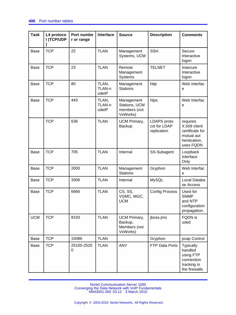
406 Port number tables
Task L4 protocol (TCP/UDP)
Port number or range
Interface Source Description Comments
Base TCP 22 TLAN ManagementSystems, UCM
SSH SecureInteractivelogon
Base TCP 23 TLAN RemoteManagementSystems
TELNET InsecureInteractivelogon
Base TCP 80 TLAN,TLAN-nodeIP
ManagementStations
http Web Interface
Base TCP 443 TLAN,TLAN-nodeIP
ManagementStations, UCMmembers (notVxWorks)
htps Web Interface
TCP 636 TLAN UCM Primary,Backup
LDAPS protocol for LDAPreplication
requiresX.509 clientcertificate formutual authentication,uses FQDN
Base TCP 705 TLAN Internal SS-Subagent LoopbackInterfaceOnly
Base TCP 2000 TLAN ManagementStations
Gryphon Web Interface
Base TCP 3306 TLAN Internal MySQL Local Database Access
Base TCP 6666 TLAN CS, SS,VGMC, MGC,UCM
Config Process Used forSNMPand NTPconfigurationpropagation.
UCM TCP 8193 TLAN UCM Primary,Backup,Members (notVxWorks)
jboss-jms FQDN isused
Base TCP 15086 TLAN Gryphon pcap Control
Base TCP 25100-25200
TLAN ANY FTP Data Ports Typicallyhandledusing FTPconnectiontracking inthe firewalls
Nortel Communication Server 1000Converging the Data Network with VoIP Fundamentals
NN43001-260 03.12 3 March 2010
Copyright © 2003-2010 Nortel Networks. All Rights Reserved.
.

Telephony Manager port numbers 407
Task L4 protocol (TCP/UDP)
Port number or range
Interface Source Description Comments
UCM TCP 31000 TLAN UCM Primary,Backup
clustered JNDIStub Download
FQDN isused
UCM TCP 31001 TLAN UCM Primary,Backup
clustered JNDIRMI queries
FQDN isused
UCM TCP 31002 TLAN UCM Primary,Backup
FQDN isused
Base TCP 32768-61000
TLAN ANY Ephemeralports
Typically handled usingTCP & FTPconnectiontracking inthe firewalls
UCM TCP 45566 -45568
TLAN UCM Primary,Backup
JGroupprotocol
FQDN isused
Base UDP 53 TLAN DNS
Base UDP 123 TLAN Any NTP, sourceport 123
Time Synchronization
Base UDP 161 TLAN TM, SNMPManagementSystems
SNMP query It is recommended to useELAN
Base UDP 514 TLAN Linux Elements
Syslog
UCM UDP 1812 TLAN UCM Members RADIUS
Base UDP 15010 TLAN AFS
Base UDP 15011 TLAN AFS
Base UDP 33600-33699
TLAN UCM Radius Central Authentication.(source port1812)
Telephony Manager port numberswhere
MGMT = Management
Nortel Communication Server 1000Converging the Data Network with VoIP Fundamentals
NN43001-260 03.12 3 March 2010
Copyright © 2003-2010 Nortel Networks. All Rights Reserved.
.

408 Port number tables
Table 124Telephony Manager (TM) port numbers
Task
L4protocol(TCP/UDP)
Port numberor range Interface Description Comments
TCP 20 FTP: Corporatedirectory and DBA
Microsoftdefault port
TCP 21 FTP: Corporatedirectory and DBA
Microsoftdefault port
TCP 21 FTP: TM 3.0 Microsoftdefault port
TCP 25 SMTP: Alarmnotification
Microsoftdefault port
MGMT TCP 80 any HTTP Web CS,Desktop Services,Web telecom billingsystem
Microsoftdefault port
MGMT TCP 135 any Login RPC, SCMused byDCOM
UDP 135 Login RPC, SCMused byDCOM
MGMT TCP 139 any NetBEUI: Windowsclient file sharing
Microsoftdefault port
UDP 161 SNMP: Alarmmanagement andmaintenance
Microsoftdefault port
MGMT UDP 162 any SNMP: Alarmtraps (LD117) andmaintenance window
Microsoftdefault port
TCP 389 CND synchronization Microsoftdefault port
TCP 513 Rlogin: SessionConnect, SystemTerminal, StationAdmin, CPND, listmanager, and ESN.
Using netstat
TCP 636 CND synchronization Microsoftdefault port(CND SSL)
MGMT TCP 1583 any Btrieve Station Admin
Nortel Communication Server 1000Converging the Data Network with VoIP Fundamentals
NN43001-260 03.12 3 March 2010
Copyright © 2003-2010 Nortel Networks. All Rights Reserved.
.

IP Phone port numbers 409
Table 124Telephony Manager (TM) port numbers (cont’d.)
Task
L4protocol(TCP/UDP)
Port numberor range Interface Description Comments
MGMT UDP 1929:2057 any DBA note: 1 port persession
Session ports
UDP 2058:2185 Data ports
MGMT TCP 3351 any Btrieve Station Admin
MGMT TCP 5099 any RMI: TM 3.0 DECT Using netstatcommand
MGMT TCP 4789 : 5045(based ondefaultport of 4789)
any Virtual SystemTerminal: Note :VT uses 1 port persession. Start with4789
The baseport can bechanged from4789
TCP 8080 HTTP: Web station ApacheTomcat Webserver
IP Phone port numbersTable 125IP Phone 200x, I20xx, and 11xx port numbers
Task
L4protocol(TCP/UDP)
Port numberor range Interface Description Comments
UDP 4100 Ethernet UNIStim is the TPS
UDP variable Ethernet RTP specified bythe TPS
UDP 5000 Ethernet Net 6
UDP 5200 Ethernet RTP src fromphone
UDP 5201 Ethernet RTCP src fromphone
Nortel Communication Server 1000Converging the Data Network with VoIP Fundamentals
NN43001-260 03.12 3 March 2010
Copyright © 2003-2010 Nortel Networks. All Rights Reserved.
.

410 Port number tables
Remote Office port numbersTable 126Remote Office port numbers
Task
L4protocol(TCP/UDP)
Port numberor range Interface Description Comments
RemoteOffice
TCP 12800 TLAN signaling
RemoteOffice
UDP/RTP 20480, 20482 TLAN RTP voice
CallPilot port numbersTable 127CallPilot port numbers
TaskL4 protocol(TCP/UDP)
Port numberor range Interface Description Comments
TCP 20 FTP
TCP 21 CLAN/ELAN
FTP
TCP 25 CLAN/ELAN
SMTP
TCP 80 CLAN/ELAN
HTTP WWW
TCP 135 CLAN/ELAN
RTP/DCOM LocationService
UDP 135 CLAN/ELAN
RTP/DCOM LocationService
TCP 137 CLAN/ELAN
NETBIOS Name Service
UDP 137 CLAN/ELAN
NETBIOS Name Service
TCP 138 CLAN/ELAN
NETBIOS DatagramService
TCP 139 CLAN/ELAN
NETBIOS SessionService
TCP 143 CLAN/ELAN
IMAP2
UDP 161 CLAN/ELAN
SNMP (if enabled)
UDP 162 CLAN/ELAN
SNMP trap (if enabled)
Nortel Communication Server 1000Converging the Data Network with VoIP Fundamentals
NN43001-260 03.12 3 March 2010
Copyright © 2003-2010 Nortel Networks. All Rights Reserved.
.

CallPilot port numbers 411
Table 127CallPilot port numbers (cont’d.)
TaskL4 protocol(TCP/UDP)
Port numberor range Interface Description Comments
TCP 389 CLAN/ELAN
LDAP
TCP 443 CLAN/ELAN
HTTP over SSL
TCP 465 CLAN/ELAN
SSMTP (SecureSMTP)
TCP 636 CLAN/ELAN
LDAP over SSL
TCP 993 IMAP over SSL
TCP 1025 CLAN/ELAN
MSDTC
TCP 1026 CLAN/ELAN
MSDTC
TCP 1027 CLAN/ELAN
MicrosoftDistribute COMServices
TCP 1028 CLAN/ELAN
MicrosoftDistribute COMServices
TCP 1029 CLAN/ELAN
Dialogic CTMS
TCP 1030 CLAN/ELAN
Dialogic CTMS
TCP 1031 CLAN/ELAN
Dialogic CTMS
TCP 1032 CLAN/ELAN
Dialogic CTMS
TCP 1036 CLAN/ELAN
CallPilotMiddlewareMaintenanceService Provider
TCP 1037 CLAN/ELAN
CallPilot CallChannel Resource
TCP 1038 CLAN/ELAN
CallPilotMultimediaResource
TCP 1039 CLAN/ELAN
CallPilot MCENotification Service
Nortel Communication Server 1000Converging the Data Network with VoIP Fundamentals
NN43001-260 03.12 3 March 2010
Copyright © 2003-2010 Nortel Networks. All Rights Reserved.
.

412 Port number tables
Table 127CallPilot port numbers (cont’d.)
TaskL4 protocol(TCP/UDP)
Port numberor range Interface Description Comments
TCP 1040 CLAN/ELAN
CallPilot MCENotification Service
TCP 1041 CLAN/ELAN
CallPilot MCENotification Service
establishedconnectionto local ports2019
TCP 1042 CLAN/ELAN
CallPilot MTA establishedconnectionto local ports2019
TCP 1045 CLAN/ELAN
CallPilot AccessProtocol
establishedconnectionto local ports2019
TCP 1046 CLAN/ELAN
CallPilot SLEE establishedconnectionto local ports2019
TCP 1047 CLAN/ELAN
IIS
TCP 1048 CLAN/ELAN
IIS
TCP 1095 CLAN/ELAN
CallPilot Blue CallRouter
TCP 1096 CLAN/ELAN
CallPilot Blue CallRouter
establishedconnectionto local ports2019
TCP 1148 CLAN/ELAN
TAPI establishedconnection toport 8888 onthe switch
TCP 1499 ODBC for reporterdatabase
TCP 2019 CLAN/ELAN
Dialogic CTMS establishedconnectionto local ports1041, 1042,1045, 1046,1096
Nortel Communication Server 1000Converging the Data Network with VoIP Fundamentals
NN43001-260 03.12 3 March 2010
Copyright © 2003-2010 Nortel Networks. All Rights Reserved.
.

Application Gateway (AG) 1000 port numbers 413
Table 127CallPilot port numbers (cont’d.)
TaskL4 protocol(TCP/UDP)
Port numberor range Interface Description Comments
TCP 2020 CLAN/ELAN
Dialogic CTMS
TCP 5631 CLAN/ELAN
pcAnywhere data
UDP 5000 Call Pilot AOS DCOM(RPC)*5
TCP 5000 Call Pilot AOS DCOM(RPC)*5
TCP 5631 pcAnywhere data if installed
UDP 5632 CLAN/ELAN
pcAnywhere data if installed
TCP 7934 CLAN/ELAN
IIS
TCP 8000 CLAN/ELAN
Dialogic CTMS
TCP 10008 CLAN/ELAN
CallPilot AccessProtocol
TCP 38037 CLAN/ELAN
msgsys Intel
CBA:Message System
TCP 56325 CLAN/ELAN
CallPilot SLEE
Application Gateway (AG) 1000 port numbersTable 128AG 1000 port numbers
ApplicationProtocol
L4protocol(TCP/UDP)
Port numberor range Description Comments
Telnet TCP 23 Connection to SignalingServer to obtain DN
Voice mailapplications
SMTP TCP 25 Connection to SNMPserver for messageforwarding
Visual voice mail
HTTP TCP 80 HTTP service port General
HTTP TCP 80 Broadcast Server push port Broadcast server
IMAP TCP 143 Connection to IMAP Visual voice mail
Nortel Communication Server 1000Converging the Data Network with VoIP Fundamentals
NN43001-260 03.12 3 March 2010
Copyright © 2003-2010 Nortel Networks. All Rights Reserved.
.

414 Port number tables
Table 128AG 1000 port numbers (cont’d.)
ApplicationProtocol
L4protocol(TCP/UDP)
Port numberor range Description Comments
SNMP TCP 161 SNMP service prot
LDAP TCP 389 Connection to LDAP server Voice mailapplications
LDAP TCP 389 Message forwarding Visual voice mail
HTTPS TCP 443 Smart agent service port Smart agent
Syslog UDP 514 Syslog service port
Proprietary TCP 5000 RUDP/UNIStim port forsignaling with phones
Voice officeapplications
HTTP TCP 8080 Outbound connection to aproxy server
HTTPS TCP 9001 AG admin tool service port General
Proprietary TCP 9005 Design studio configurationport
General
HTTP TCP 9998 Broadcast Server push port
Proprietary TCP 44443 GXAS service port IP phone 2007
RTP TCP 50004 RTP traffic for BroadcastServer
RTCP UDP 50005 RTCP receive port formonitoring RTP trafficstatistics
Voice officeapplications
HTTP TCP 9014, 9025 AG cluster communicationsport
General
RTP UDP 20480:20511 RTP receive ports for visualvoice mail
Visual voice mailand zone paging
Proprietary TCP configurable Connection to propertymanagement system
Guest service
Contact Center 6.0 port numbersFor Contact Center 6.0 port numbers, see Symposium documentation.
TLAN subnet stateless packet filteringTable 129 "TLAN subnet : Stateless packet filtering configuration" (page415) describes a stateless packet filtering configuration. The primaryintent of this configuration is to secure management access to theCommunication Server 1000 system using the TLAN subnet.
Nortel Communication Server 1000Converging the Data Network with VoIP Fundamentals
NN43001-260 03.12 3 March 2010
Copyright © 2003-2010 Nortel Networks. All Rights Reserved.
.

TLAN subnet stateful packet filtering 415
The table rules are for the TLAN subnet only. IP Phones are assumedto be deployed on client subnets throughout the IP network. All otherTCP and UDP ports that run on the TLAN network interfaces are forsystem control traffic, which should not be sent through the packet filter.Optionally, drop all management traffic into the TLAN subnet.
Table 129TLAN subnet : Stateless packet filtering configuration
Rule#
TaskApp/
Interface
SourceIP
address
SourceTCP/UDPport
Dest.IP
address
Protocoltype
Dest.TCP/UDPport Action Description
System Management
1 SystemMGMT
MGMT ignore TLANsubnet
any any Forward Allow MGMTSystem
2 SystemMGMT
any ignore TLANsubnet
TCP 21 Drop FTP
3 SystemMGMT
any ignore TLANsubnet
TCP 23 Drop Telnet
4 SystemMGMT
any ignore TLANsubnet
TCP 80 Drop HTTPElement
Management
5 SystemMGMT
any ignore TLANsubnet
TCP 111 Drop RPC
6 SystemMGMT
any ignore TLANsubnet
UDP 162 Drop SNMP
7 SystemMGMT
any ignore TLANsubnet
TCP 513 Drop rlogin
Firewall
8 DefaultRule
any ignore TLANsubnet
UDP any Forward DefaultAction
TLAN subnet stateful packet filteringTable 130 "TLAN subnet : stateful packet filtering" (page 416) describesrules for a stateful firewall only; they do not apply to a non:stateful firewall.IP Phones are assumed to be deployed on client subnets throughout theIP network. All other TCP and UDP ports running on the TLAN networkinterfaces are for system control traffic, which should not be sent throughthe packet filter. Optionally, drop all management traffic into the TLANsubnet.
Nortel Communication Server 1000Converging the Data Network with VoIP Fundamentals
NN43001-260 03.12 3 March 2010
Copyright © 2003-2010 Nortel Networks. All Rights Reserved.
.

416 Port number tables
Table 130TLAN subnet : stateful packet filtering
Rule#
TaskApp/
Interface
SourceIP
add.
SourceTCP/UDPport
Dest.IP
add.Protocol
type
Dest.TCP/UDPport Action Description
System Management
1SystemMGMT
MGMT ignoreTLANsubnet
TCP 21 Forward FTP
2SystemMGMT
MGMT ignoreTLANsubnet
TCP 22 Forward SSH
3SystemMGMT
MGMT ignoreTLANsubnet
TCP 23 Forward Telnet
4SystemMGMT
MGMT ignoreTLANsubnet
TCP 80 ForwardElementManager
5SystemMGMT
MGMT ignoreTLANsubnet
TCP 513 Forward rlogin
6SystemMGMT
MGMT ignoreTLANsubnet
UDP 162 Forward SNMP
VoIP Signaling
7SigSvr /Gatekpr
any ignoreTLANsubnet
TCP 1720 ForwardH.323
Signaling
8 SIP any ignoreTLANsubnet
TCP 5060 ForwardSIP Signaling(configurable)
9FirmwareDownload
any ignoreTLANsubnet
UDP 69 Forward TFTP
10 H.323 any ignoreTLANsubnet
UDP 1718 ForwardH.323
Signaling
11 H.323 any ignoreTLANsubnet
UDP 1719 ForwardH.323
Signaling
12 TPS any ignoreTLANsubnet
UDP 4100 ForwardIP Phone 200
x signaling
13 SIP any ignoreTLANsubnet
UDP 5060 ForwardSIP Signaling(configurable)
14 TPS any ignoreTLANsubnet
UDP 5100 ForwardIP Phone 200x signaling
(configurable)
15FirmwareDownload
any ignoreTLANsubnet
UDP 5105 Forward UNIStim FTP
16 TPS any ignoreTLANsubnet
UDP 7300 ForwardIP Phone 200x
signaling
Nortel Communication Server 1000Converging the Data Network with VoIP Fundamentals
NN43001-260 03.12 3 March 2010
Copyright © 2003-2010 Nortel Networks. All Rights Reserved.
.

ELAN subnet packet filtering 417
Table 130TLAN subnet : stateful packet filtering (cont’d.)
Rule#
TaskApp/
Interface
SourceIP
add.
SourceTCP/UDPport
Dest.IP
add.Protocol
type
Dest.TCP/UDPport Action Description
17VirtualOffice
any ignoreTLANsubnet
UDP 16500 Forward
Virtual Officesignaling
Network connect serverconfigurable
18VirtualOffice
any ignoreTLANsubnet
UDP 16501 ForwardVirtual Office
Signaling
19SIP GW
SPSany ignore
TLANsubnet
TCP 5061 Forward SIP Signaling
VoIP Media
20 SMC any ignoreTLANsubnet
UDP5200:5263
ForwardRTP/RTCPvoice media
Firewall
21 Firewall any ignoreTLANsubnet
ignore any Drop Default Action
ELAN subnet packet filteringTable 131 "ELAN subnet : packet filtering" (page 417) describes a packetfiltering configuration suitable for a routable ELAN subnet. These filters areeffective for stateless and stateful packet filters.
Table 131ELAN subnet : packet filtering
Rule#
Task(App./
Interface)SourceIP add.
SourceTCP/UDPport
Dest.IP add.
Protocoltype
Dest.TCP/UDPport Action Description
System Management
1SystemMGMT
MGMT ignoreELANsubnet
TCP 21 Forward FTP
2SystemMGMT
MGMT ignoreTLANsubnet
TCP 22 Forward SSH
3SystemMagma
MGMT ignoreELANsubnet
TCP 23 Forward Telnet
4SystemMagma
MGMT ignoreELANsubnet
TCP 80 ForwardHTTP
ElementManagement
Nortel Communication Server 1000Converging the Data Network with VoIP Fundamentals
NN43001-260 03.12 3 March 2010
Copyright © 2003-2010 Nortel Networks. All Rights Reserved.
.

418 Port number tables
Table 131ELAN subnet : packet filtering (cont’d.)
Rule#
Task(App./
Interface)SourceIP add.
SourceTCP/UDPport
Dest.IP add.
Protocoltype
Dest.TCP/UDPport Action Description
5SystemMagma
MGMT ignoreELANsubnet
TCP 513 Forward rlogin
6SystemMagma
MGMT ignoreELANsubnet
UDP 162 Forward SNMP query
7SystemMagma
MGMT ignoreELANsubnet
UDP1929:2
185Forward DBA for TM
System Signaling
8System
SignalingCC6 ignore
CallServer
TCP 8888 ForwardCC6 AML
Link
Note: Rule "8" (page 418) applies only to a system with a Contact Center 6 system using a singlenetwork interface to the Nortel server subnet.
Firewall
9 Firewall any IgnoreELANsubnet
ignore any DropDefaultaction
Nortel Communication Server 1000Converging the Data Network with VoIP Fundamentals
NN43001-260 03.12 3 March 2010
Copyright © 2003-2010 Nortel Networks. All Rights Reserved.
.

419.
AppendixDHCP supplemental information
To understand how the IP Phones 200x and the IP Softphone 2050acquire the needed network configuration parameters automatically, thichapter briefly describes the Dynamic Host Configuration Protocol (DHCP).
Read this section if you are unfamiliar with DHCP. Topics are helpful forthe configuration and future maintenance of the DHCP server and ensurecorrect implementation with IP Phones.
DHCP is an extension of BootP. Like BootP, it operates on theclient:server model. However, DHCP has more message types thanBootP. DHCP enables the dynamic allocation of IP addresses to differentclients. It can be used to configure clients by supplying the networkconfiguration parameters, such as gateway or router IP addresses.
DHCP also includes a lease system that controls the duration an IPaddress is leased to a client. The client can request a specific leaselength, or the administrator can determine the maximum lease length.A lease can range from 1 minute to 99 years. When the lease is up orreleased by the client, the DHCP server automatically retrieves it andreassigns it to other clients, if necessary. This is an efficient and accurateway to configure clients quickly and saves the administrator from anotherwise repetitive task. IP addresses can be shared among clients thatdo not require permanent IP addresses.
Navigation“Introduction to DHCP” (page 420)
“DHCP messages” (page 420)
“DHCP message format” (page 420)
“DHCP message exchange” (page 421)
“DHCP options” (page 422)
“Vendor Specific/Encapsulated option” (page 422)
Nortel Communication Server 1000Converging the Data Network with VoIP Fundamentals
NN43001-260 03.12 3 March 2010
Copyright © 2003-2010 Nortel Networks. All Rights Reserved.
.

420 DHCP supplemental information
“Site Specific option” (page 422)
“IP acquisition sequence” (page 423)
“Case 1” (page 423)
“Case 2” (page 424)
“Case 3” (page 425)
“Multiple DHCPOFFER messages” (page 426)
“IP Phone support for DHCP” (page 427)
“Full DHCP” (page 427)
“Partial DHCP” (page 431)
“DHCP Auto Discovery” (page 431)s
Introduction to DHCPDHCP messages
There are seven different DHCP messages. Each message relayscertain information between the client and server. See Table 132 "DHCPmessage types" (page 420).
Table 132DHCP message types
DHCP Message Types Description
DHCPDISCOVER Initiates a client request to all servers.
DHCPOFFER Offer from server following client request.
DHCPREQUEST Requests a particular server for services.
DHCPAK Notifies client that requested parameters canbe met.
DHCPNAK Notifies client that requested parameterscannot be met.
DHCPDECLINE Notifies server that the offer is unsatisfactoryand will not be accepted.
DHCPRELEASE Notifies server that IP address is no longerneeded.
DHCP message formatThe DHCP message format shown in Figure 103 "DHCP message format"(page 421) is common to all DHCP messages. Each message consistsof 15 fields: 14 fixed:length fields and one variable length field. Thefixed:length fields must be the specified number of bytes, as indicated inthe brackets. If there is not enough data, or there is no data at all, zerosare used to fill in the extra spaces.
Nortel Communication Server 1000Converging the Data Network with VoIP Fundamentals
NN43001-260 03.12 3 March 2010
Copyright © 2003-2010 Nortel Networks. All Rights Reserved.
.

Introduction to DHCP 421
Figure 103DHCP message format
The Options field is the only field with a variable length. It is optional,but very important, as it transports additional network configurationparameters. The DHCP options are the actual subfields used in a project.
DHCP message exchangeFor a client to receive services from a DHCP server, an exchange ofDHCP messages between the client and server must take place. Thesequence and types of DHCP message exchanged can differ, but themechanism of acquiring and supplying information remains the same.
Usually the client initiates the exchange with a DHCP message broadcast.Using a broadcast enables the client to send messages to all servers onthe network without having an associated IP address. The broadcast islocal to the LAN, unless a DHCP relay agent is present to forward thepacket.
At this point, the client has no information about the server or the IPaddress it is going to receive (unless it is requesting a renewal), so thefields in the DHCP message are empty. However, the client knows its ownMAC address and includes it in the Client hardware address field. Theclient can also have a list of parameters it would like to acquire and canrequest them from the DHCP server by including the Parameter RequestList option (Option Code 55) in the DHCPDISCOVER message.
When the DHCP server sees the broadcast, it responds by broadcastingits own DHCP message. The server, as it knows more about the network,can fill in most of the information in the message. For example, information
Nortel Communication Server 1000Converging the Data Network with VoIP Fundamentals
NN43001-260 03.12 3 March 2010
Copyright © 2003-2010 Nortel Networks. All Rights Reserved.
.

422 DHCP supplemental information
such as the server IP address and gateway IP address are included intheir respective fields. As the client does not have an IP address yet, theserver uses the client MAC address to uniquely identify it. When the clientsees the broadcast, it matches its MAC address against the one in themessage.
DHCP optionsDHCP options are the subfields of the Options field. They carry additionalnetwork configuration information requested by the client, such as the IPaddress lease length and the subnet mask.
Each DHCP option has an associated option code and a format forcarrying data. Usually the format is as follows:
Option code Length Data
There are two categories of DHCP options: standard and non:standard.The standard options are predefined by the industry. The non:standardoptions are user defined to fit the needs of a particular vendor or site.
There are a total of 255 DHCP option codes, where option codes 0 and255 are reserved, 1 to 77 are predefined, 1 to 254 can be used for VendorSpecific Options, and 128 to 254 are designated for Site Specific Options.This arrangement enables future expansion and is used as a guidelinefor choosing option codes.
Vendor Specific/Encapsulated optionThe Vendor Specific DHCP options are vendor:defined options for carryingvendor:related information. It is possible to override predefined standardoptions; however, doing so can cause conflict when used with componentsthat follow the industry standard.
A useful option is the standard Vendor Encapsulated option – code 43. Itis used to encapsulate other DHCP options as suboptions. For example,the IP Phone 2004 requires Vendor Specific Voice Gateway Media Cardinformation. The vendor, Nortel, decides to carry this information in one ofseveral Site Specific options and then encapsulate it into option 43. Asthe information is specific to a Nortel product, it is vendor:specific. Afterencapsulation, the information appears as one or more suboptions insideoption 43, which the IP Phone decodes.
Site Specific optionAnother way to transport the Voice Gateway Media Card information isthrough Site Specific options. These are unused DHCP options that havenot been predefined to carry standard information. Unlike the VendorSpecific options, the information transported is site specific and optioncodes 128 to 254 are used for encoding.
Nortel Communication Server 1000Converging the Data Network with VoIP Fundamentals
NN43001-260 03.12 3 March 2010
Copyright © 2003-2010 Nortel Networks. All Rights Reserved.
.

IP acquisition sequence 423
For Nortel IP Phones, the Voice Gateway Media Card information involvesthe location of the Voice Gateway Media Card in the network. This variesfor different sites and can be implemented in a Site Specific option. If theVendor Encapsulation option is used, the information is first encoded in aSite Specific option. Nortel has provided a list of five possible Site Specificoption codes to implement the Voice Gateway Media Card information.Only one of the five codes must be configured to carry the information, butthe choice is available to offset the possibility that the option code chosenhas been used for other purposes.
IP acquisition sequenceThis section focuses on the mechanics and sequence of the DHCPmessage exchange as the IP Phone uses DHCP for IP acquisition.Although the IP Phone requests many network configuration parametersas well as an IP address, the following cases focus on the concept ofhow instead of what information is acquired. The IP Phone is used as thesample client, but the situations apply to other DHCP clients as well.
Case 1Case 1 is a typical situation where an IP Phone 2004 requests servicesfrom a DHCP server, shown in the following figure.
Figure 104IP acquisition phase: Case 1
1. The IP Phone initiates the sequence by broadcasting aDHCPDISCOVER message.
2. A DHCP server on the network sees the broadcast, reads themessage, and records the MAC address of the client.
3. The DHCP server checks its own IP address pools for an available IPaddress and broadcasts a DHCPOFFER message if one is available.Usually the server ensures the IP address is free using ARP or ping.
Nortel Communication Server 1000Converging the Data Network with VoIP Fundamentals
NN43001-260 03.12 3 March 2010
Copyright © 2003-2010 Nortel Networks. All Rights Reserved.
.

424 DHCP supplemental information
4. The IP Phone sees the broadcast and after matching its MAC addresswith the offer, reads the rest of the message to find out what else isbeing offered.
5. If the offer is acceptable, the IP Phone sends out a DHCPREQUESTmessage with the DHCP server IP address in the Server IP addressfield.
6. The DHCP server matches the IP address in the Server IP addressfield against its own, to find out to whom the packet belongs.
7. If the IP addresses match and there is no problem supplying therequested information, the DHCP server assigns the IP address to theclient by sending a DHCPACK message.
8. If the final offer is not rejected, the IP acquisition sequence is complete.
Case 2The IP acquisition is unsuccessful if either the server or the client decidesnot to participate, as follows:
• If the DHCP server cannot supply the requested information, it sends aDHCPNAK message and no IP address is assigned to the client. Thiscan happen if the requested IP address has already been assignedto a different client. See Figure 105 "IP acquisition sequence: Case2" (page 425).
• If the client decides to reject the final offer (after the server sends aDHCPACK message), the client sends a DHCPDECLINE message tothe server, to tell the server the offer is rejected. The client must restartthe IP acquisition by sending another DHCPDISCOVER message insearch of another offer.
Nortel Communication Server 1000Converging the Data Network with VoIP Fundamentals
NN43001-260 03.12 3 March 2010
Copyright © 2003-2010 Nortel Networks. All Rights Reserved.
.

IP acquisition sequence 425
Figure 105IP acquisition sequence: Case 2
Case 3When a client is finished with a particular IP address, it sends aDHCPRELEASE message to the server which reclaims the IP address. Ifthe client requires the same IP address again, it can initiate the process asfollows:
1. The IP Phone broadcasts a DHCPREQUEST to a particular DHCPserver by including the server IP address in the Server IP Addressfield of the message. As it knows the IP address it wants, it requestsit in the DHCP message.
2. The DHCP server sends a DHCPACK message if all the parametersrequested are met.
Case 1 is similar to Case 3, except the first two messages have beeneliminated. This reduces the amount of traffic produced on the network.See Figure 106 "IP acquisition sequence: Case 3" (page 426).
Nortel Communication Server 1000Converging the Data Network with VoIP Fundamentals
NN43001-260 03.12 3 March 2010
Copyright © 2003-2010 Nortel Networks. All Rights Reserved.
.

426 DHCP supplemental information
Figure 106IP acquisition sequence: Case 3
Multiple DHCPOFFER messagesIn some networks, if more than one DHCP server is present, a clientcan receive multiple DHCPOFFER messages. Under these situations,the IP acquisition sequence depends on the client. The client canwait for multiple offers, or accept the first offer it receives. If it acceptsmultiple offers, it compares them before choosing one with the mostfitting configuration parameters. When a decision is made, the messageexchange is the same as if there is only one DHCP server and proceedsas in the previous cases. The servers that were not chosen to provide theservice do not participate in the exchange.
For example, the IP Phone 2004 responds only to DHCPOFFERmessages that have the same unique string identifier, (Nortel:i2004:A),as the IP Phone 2004. This string must appear in the beginning of thelist of Voice Gateway Media Card parameters. Without this string, the IPPhone 2004 does not accept the DHPCOFFER, even if all parametersrequested and Voice Gateway Media Card information are present. Ifno valid DHCPOFFER messages are sent, the IP Phone 2004 keepsbroadcasting in search of a valid offer.
With multiple DHCP servers on the same network, a problem canoccur if any two of the servers have overlapping IP address rangesand no redundancy. DHCP redundancy is a property of DHCP servers.Redundancy enables different DHCP servers to serve the same IPaddress ranges simultaneously. Administrators must be aware that not allDHCP servers have this capability.
Nortel Communication Server 1000Converging the Data Network with VoIP Fundamentals
NN43001-260 03.12 3 March 2010
Copyright © 2003-2010 Nortel Networks. All Rights Reserved.
.

IP Phone support for DHCP 427
IP Phone support for DHCPThis section covers the three uses of DHCP (Full, Partial, and VLAN AutoDiscovery) by IP Phones 2002, 2004, and 2007.
An IP Phone 2004:aware DHCP server is needed only for the Full DHCPand VLAN Auto discovery. An IP Phone can obtain its IP address andsubnet mask using Partial DHCP. The IP Phone 2004 aware part returnsthe Node IP and registration port number. In the case of the DHCP AutoDiscovery, it returns the VLAN IDs. Separate DHCP vendor:specificentries are needed for the Full DHCP data and the VLAN Auto Discoverydata. When using VLAN Auto Discovery, both Full DHCP and VLANAuto Discovery must be configured. Full DHCP and Auto VLAN areimplemented as separate functions in the IP Phone firmware. However, inpractice, Full DHCP and Auto VLAN are frequently used together.
Full DHCPDHCP support in the IP Phone requires sending a Class Identifieroption with the value (Nortel:i2004:A) in each DHCP DHCPOFFER andDHCPACK message. Additionally, the telephone checks for either aVendor Specific option message with a specific, unique to Nortel IP Phone2004, encapsulated sub:type, or a Site Specific DHCP option.
In either case, an IP Phone 2004:specific option must be returned by theIP Phone 2004 aware DHCP server in all Offer and Acknowledgement(ACK) messages. The IP Phone uses this option’s data it to configure theinformation required to connect to the TPS.
The DHCP response is parsed to extract the IP Phone IP address, subnetmask, and gateway IP address. The Vendor Specific field is then parsed toextract the Server 1 (minimum) and optional Server 2. By default, Server 1is always assumed to be the primary server after a DHCP session.
For the IP Phone to accept Offers/Acks, the messages must contain allof the following:
• A router option (requires a default router to function)
• A subnet mask option
• A Vendor Specific or Site Specific option as specified below.
— Initial DHCP implementation required only the Vendor Specificencapsulated suboption. In interoperations testing with WindowsNT (up to Service Release 4), it was discovered that Windows NTdoes not properly adhere to RFC 1541. As a result this option isnot possible. The implementation was changed to add support foreither Vendor Specific suboptions or Site Specific options. This
Nortel Communication Server 1000Converging the Data Network with VoIP Fundamentals
NN43001-260 03.12 3 March 2010
Copyright © 2003-2010 Nortel Networks. All Rights Reserved.
.

428 DHCP supplemental information
new extension has been tested and verified to work with WindowsNT.
— The site:specific options are all DHCP options between 128 (0x80)and 254 (0xFE). These options are reserved for Site Specific useby the DHCP RFCs.
Format for IP Phone 2004 Terminal DHCP Class Identifier FieldAll IP Phones (IP Phones 2x and IP Softphone 2050) fill in the Class IDfield of the DHCP Discovery and Request messages with the following:
Nortel:i2004:AWhere:
• ASCII encoded, NULL (0x00) terminated
• unique to IP Phone 2004
• :A is the unique identifier for this version
Format for IP Phone 2004 Terminal DHCP Encapsulated VendorSpecific FieldThis suboption must be encapsulated in a DHCP Vendor Specific Option(see RFC 1541 and RFC 1533) and returned by the DHCP server as partof each DHCP OFFER and ACK message for the IP Phone to acceptthese messages as valid.
The IP Phone parses this option data and uses it to configure theinformation required to connect to the TPS.
Note 1: Either this encapsulated suboption must be present, or asimilarly encoded site:specific option must be sent. See “Format of theEncapsulated Vendor Specific Sub:option field” (page 428). Configurethe DHCP server to send one or the other but not both.
Note 2: The choice of using either Vendor Specific or Site Specificoptions is provided to enable Windows NT DHCP servers to be usedwith the IP Phone. Windows NT servers do not properly implement theVendor Specific Option and as a result, Windows NT implementationsmust use the Site Specific version.
Format of the Encapsulated Vendor Specific Sub:option fieldThe format of the Encapsulated Vendor Specific Suboption field is asfollows:
• Type (1 octet): 5 choices are provided (0x80, 0x90, 0x9d, 0xbf, 0xfb[128, 144, 157, 191, 251]), which allow the IP Phone to operate when
Nortel Communication Server 1000Converging the Data Network with VoIP Fundamentals
NN43001-260 03.12 3 March 2010
Copyright © 2003-2010 Nortel Networks. All Rights Reserved.
.

IP Phone support for DHCP 429
one or more value is already in use by a different vendor. Select onlyone TYPE byte.
• Length (1 octet): variable—depends on message content.
• Data (length octets): ASCII based with the following format:
Nortel:i2004 :A,iii.jjj.kkk.lll:ppppp,aaa,rrr;iii.jjj.kkk.lll:pppp,aaa,rrr.
The components in this string are described in Table 133"Encapsulated Vendor Specific Sub:option field" (page 429).
Table 133Encapsulated Vendor Specific Sub:option field
Parameter Description
Nortel:i2004:A Uniquely identifies this as the Nortel option
Signifies this version of this specification
iii.jjj.kkk.lll:ppppp Identifies the IP address:port for server (ASCII encoded decimal)
aaa Identifies the Action for server (ASCII encoded decimal, range 0–255)
rrr Identifies the retry count for server (ASCII encoded decimal, range 0 – 255).This string can be NULL terminated although the NULL is not required forparsing.
ACSII symbols The comma (,) is used to separate fields
The semicolon (;) is used to separate Primary from Secondary serverinformation
The period (.) is used to signal the end of the structure
Table 134 "Nortel option string" (page 429) shows the pieces of the Norteloption string. The Nortel designator Nortel:i2004:A is separated fromthe Connector Server stings using a comma. The Connect Servers areseparated using a semicolon.
Table 134Nortel option string
Nortel:i2004:A,iii.jjj.kkk.lll:ppppp,aaa,rrr;iii.jjj.kkk.lll:pppp,aaa,rrr.
Nortel ClassIdentifier Field
comma PrimaryConnect Server
semicolon SecondaryConnect Server
period
Nortel:i2004:A , iii.jjj.kkk.lll:ppppp,aaa,rrr
; iii.jjj.kkk.lll:ppppp,aaa,rrr
.
Note 1: aaa and rrr are ASCII encoded decimal numbers with arange of 0 to 255. They identify the Action Code and Retry Count,respectively, for the associated TPS server. Internally to IP Phone 2004they are stored as 1 octet (0x00 to 0xFF). Note that these fields must beno more than 3 digits long.
Nortel Communication Server 1000Converging the Data Network with VoIP Fundamentals
NN43001-260 03.12 3 March 2010
Copyright © 2003-2010 Nortel Networks. All Rights Reserved.
.

430 DHCP supplemental information
Note 2: The string enables the configuration of information for twoConnect Servers. One Connect Server exists for each IP node. In thetypical system configuration of a single IP node, only the primary ConnectServer is required. In this case, the primary Connect Server string mustbe ended with a period (.) instead of a semicolon (;). For example,Nortel:i2004:A,iii.jjj.kkk.lll:ppppp,aaa,rrr.If the secondary Connect Serverportion of the string is specified, then the string information is typicallythe same as the primary Connect Server information. For example:Nortel:i2004:A,iii.jjj.kkk.lll:ppppp,aaa,rrr;iii.jjj.kkk.lll:ppppp,aaa,rrr.Whenthe Enhanced Redundancy for IP Line Nodes feature is used, twodifferent Connect Server strings can be configured, separated with asemicolon (;). This enables the telephone to register to two differentnodes. For more information about the Enhanced Redundancy forIP Line Node feature, see Signaling Server IP Line ApplicationsFundamentals (NN43001-125) ().
Note 3: Action code values (0 to 255):1—UNIStim Hello (currently only this type is a valid choice)all other values (0, 2 to 255)—reserved
Note 4: iii,jjj,kkk,lll are ASCII:encoded, decimal numbers representingthe IP address of the server. They do not need to be 3 digits long asthe period (.) and colon (:) delimiters guarantee parsing. For example,001, 01, and 1 would all be parsed correctly and interpreted as value0x01 internal to the IP Phone 2004. Note that these fields must be nomore than three digits long each.
Note 5: ppppp is the port number in ASCII encoded decimal. The portnumber must be set to 4100.
Note 6: In all cases, the ASCII encoded numbers are treated asdecimal values and all leading zeros are ignored. More specifically,a leading zero does not change the interpretation of the value to beOCTAL encoded. For example, 0021, 021, and 21 are all parsed andinterpreted as decimal 21.
Format for IP Phone 2004 Terminal DHCP Site Specific optionThis option uses the reserved for Site Specific use DHCP options (number128 to 254, see RFC 1541 and RFC 1533) and must be returned by theDHCP server as part of each DHCP OFFER and ACK message for the IPPhone to accept these messages as valid.
The IP Phone pulls the relevant information out of this option and usesit to configure the IP address and so on for the primary and (optionally)secondary TPSs.
Note 1: Either this Site Specific option must be present or a similarlyencoded vendor:specific option must be sent (as previously described).For example, configure the DHCP server to send one or the other butnot both.
Nortel Communication Server 1000Converging the Data Network with VoIP Fundamentals
NN43001-260 03.12 3 March 2010
Copyright © 2003-2010 Nortel Networks. All Rights Reserved.
.

IP Phone support for DHCP 431
Note 2: The choice of using either Vendor Specific or Site Specificoptions is provided to enable Windows NT DHCP servers to be usedwith the IP Phone. Windows NT servers do not properly implement theVendor Specific Option and as a result, Windows NT implementationsmust use the Site Specific version.
Format of the DHCP Site Specific fieldThe format of the DHCP Site Specific field is the same as the format ofthe Encapsulated Vendor Specific Suboption field. See “Format of theEncapsulated Vendor Specific Sub:option field” (page 428).
Partial DHCPPartial DHCP is the default DHCP response from a DHCP server that hasnot been configured to provide the Vendor Specific information. UsingPartial DHCP, an IP Phone can obtain its IP address, subnet mask, andgateway IP address. The remainder of the configuration information ismanually entered at the IP Phone.
DHCP Auto DiscoveryDHCP Auto Discovery must be used only if the telephone and PC are:
• connected to the same Layer 2 switch port through a three:port switch
• on separate subnets
The DHCP server can be configured to supply the VLAN information tothe IP Phones. The server uses the Site Specific option in the DHCP offermessage to convey the VLAN information to the IP Phone.
Configuring a DHCP Server for VLAN Discovery is optional. Thisconfiguration is done in addition to that for Full DHCP configuration and itis required only when configuring the VLAN Auto Discovery.
This method is based on the assumption that the default VLAN is the dataVLAN and the tagged VLAN is the voice VLAN. Enter the voice VLANinformation into the data VLAN and subnet’s DHCP server. Enter thestandard IP Phone configuration string into the voice VLAN and subnetDHCP server pool.
The following definition describes the IP Phone 2004:specific, Site Specificoption. This option uses the reserved for Site Specific use DHCP options(DHCP option values 128 to 254) and must be returned by the DHCPserver as part of each DHCPOFFER and DHCPACK message for the IPPhone to accept these messages as valid. The IP Phone extracts therelevant information and uses the information to configure itself.
Format of the fieldThe format of the field is: Type, Length, Data.
Nortel Communication Server 1000Converging the Data Network with VoIP Fundamentals
NN43001-260 03.12 3 March 2010
Copyright © 2003-2010 Nortel Networks. All Rights Reserved.
.

432 DHCP supplemental information
Type (1 octet):There are five choices:
• 0x80 (128)
• 0x90 (144)
• 0x9d (157)
• 0xbf (191)
• 0xfb (251)
Providing a choice of five types enables the IP Phones to operate if avalue is already in use by a different vendor. Select only one Type byte.
Length (1 octet):This is variable; it depends on message content.
Data (length octets):ASCII based format: VLAN:A:XXX+YYY+ZZZ.where:
• VLAN– A: – uniquely identifies this as the Nortel DHCP VLANdiscovery. Additionally, the –A signifies this version of this spec. Futureenhancements could use –B for example.
• ASCII plus (+) or comma (,) is used to separate fields.
• ASCII period (.) is used to signal the end of the structure.
• XXX, YYY and ZZZ are ASCII encoded decimal numbers with a rangeof 0 to 4095. The number is used to identify the VLAN IDs. There area maximum of 10 VLAN IDs can be configured in the current version.The strings none or NONE means no VLAN (default VLAN).
The DHCP OFFER message carrying VLAN information is sent from theDHCP server without a VLAN tag. However, the switch port adds a VLANtag to the packet. The packet is untagged at the port of the IP Phone.
Nortel Communication Server 1000Converging the Data Network with VoIP Fundamentals
NN43001-260 03.12 3 March 2010
Copyright © 2003-2010 Nortel Networks. All Rights Reserved.
.

433.
AppendixSetup and configuration of DHCPservers
Navigation• “Install a Windows NT 4 or Windows 2000 server” (page 433)
• “Configure a Windows NT 4 server with DHCP” (page 433)
• “Configure a Windows 2000 server with DHCP” (page 436)
• “Install ISC DHCP Server” (page 441)
• “Configure ISC DHCP Server” (page 441)
• “Install and configure a Solaris 2 server” (page 444)
Install a Windows NT 4 or Windows 2000 serverTo set up the Windows NT 4 or Windows 2000 server, follow theinstructions provided in the installation booklet. After completion, install thelatest Service Pack and make sure the DHCP Manager is included.
ATTENTIONIf you install a Windows NT 4 server with Service Pack 4 or later, follow theinstallation instructions included with the server hardware.
Configure a Windows NT 4 server with DHCPConfigure a Windows NT 4 server with DHCP services using the DHCPManager provided. Follow the steps in “Launching the DHCP Manager InWindows NT 4” (page 433) to launch the DHCP Manager.
Launching the DHCP Manager In Windows NT 4
Step Action
1 Click the Windows Start button.
Nortel Communication Server 1000Converging the Data Network with VoIP Fundamentals
NN43001-260 03.12 3 March 2010
Copyright © 2003-2010 Nortel Networks. All Rights Reserved.
.

434 Setup and configuration of DHCP servers
2 Select Programs, Administrative tools (Common), DHCPManager.
The DHCP Manager window appears.
3 Double:click Local Machines in the left pane.
The Create Scope : (Local) window appears.Figure 107Define a new scope
4 Create and fill in the information.
5 Click OK when finished.
6 In the DHCP Manager : (Local) window, highlight the scope thatserves the IP Phones clients.
7 From the DHCP Options menu, select Default Values.
The DHCP Options : Default Values window appears.
8 Click the New button. See Figure 108 "Define the Nortel:specificoption" (page 435).
The Change Option Type window appears.
Nortel Communication Server 1000Converging the Data Network with VoIP Fundamentals
NN43001-260 03.12 3 March 2010
Copyright © 2003-2010 Nortel Networks. All Rights Reserved.
.

Configure a Windows NT 4 server with DHCP 435
Figure 108Define the Nortel:specific option
9 Fill in the information and click OK when finished.
10 Click OK again.
11 From the DHCP Manager : (Local) window, highlight the scopeto which you want to add the DHCP options.
12 From the DHCP Options menu, select Scope.
The DHCP Options Scope window appears.
13 Choose standard DHCP options from the left panel and clickAdd to add them to the right panel.Figure 109Add standard DHCP options to scope
14 Click Edit Array .
Nortel Communication Server 1000Converging the Data Network with VoIP Fundamentals
NN43001-260 03.12 3 March 2010
Copyright © 2003-2010 Nortel Networks. All Rights Reserved.
.

436 Setup and configuration of DHCP servers
The IP Address Array Editor window appears.
15 Edit the default value and then click OK.
16 Click OK again.
17 From the DHCP Manager : (Local) window, highlight the scopethat needs to be activated.
18 From the DHCP Options menu, select Scope.
The DHCP Options Scope window appears.
19 Click Activate.
The light bulb next to the scope should turn yellow. See Figure110 "Activate the scope" (page 436) on Figure 110 "Activate thescope" (page 436).Figure 110Activate the scope
If DHCP Auto Discovery needs to be configured, see “DHCPAuto Discovery” (page 431).
--End--
Configure a Windows 2000 server with DHCPConfigure a Windows 2000 server with DHCP services using the DHCPManager.
Launching the DHCP Manager in Windows 2000
Step Action
1 Click the Windows Start button.
2 Select Programs, Administrative Tools, DHCP.
The administrative console window appears. See Figure 111"Windows 2000 administration console" (page 437).
Nortel Communication Server 1000Converging the Data Network with VoIP Fundamentals
NN43001-260 03.12 3 March 2010
Copyright © 2003-2010 Nortel Networks. All Rights Reserved.
.

Configure a Windows 2000 server with DHCP 437
Figure 111Windows 2000 administration console
3 Highlight DHCP and expand the DHCP option (if it is not alreadyexpanded).
4 Highlight the server and right:click to display the shortcut menu.
5 Select Set Predefined Options from the menu.
Do not go into the Vendor Specific settings. The PredefinedOptions and Values window appears.
Nortel Communication Server 1000Converging the Data Network with VoIP Fundamentals
NN43001-260 03.12 3 March 2010
Copyright © 2003-2010 Nortel Networks. All Rights Reserved.
.

438 Setup and configuration of DHCP servers
Figure 112Predefined Options and Values
6 Click Add.
The Change Option Type window appears.Figure 113Change Options Type
7 In the Name box, enter the desired Name.
For this example, the name of Nortel:i2004:A is entered. SeeFigure 113 "Change Options Type" (page 438).
8 From the Code box, select Code 128.
9 Click OK to close the window.
The Predefined Options and Values window appears with thestring 128 Nortel:i2004:A entered in the Option name field.
Nortel Communication Server 1000Converging the Data Network with VoIP Fundamentals
NN43001-260 03.12 3 March 2010
Copyright © 2003-2010 Nortel Networks. All Rights Reserved.
.

Configure a Windows 2000 server with DHCP 439
Figure 114Predefined Options and Values with data entered
10 In the Value area, enter the following string in the String field:Nortel:i2004:A,x.x.x.x:4100,1,10; using the following guidelines:
• The string is case:sensitive.
• Place a period at the end of the string.
• Commas are used as separators.
• Spaces are not allowed.
• x.x.x.x is the IP address of the IP Telephony node.
• If it is a BCM, replace the 4100 value with 7000.
11 Click OK.
12 Click the scope (Scope [x.x.x.x] name) to expand, and thenclick Scope Options.
The Scope Options window appears.Figure 115Scope and Scope Options
Nortel Communication Server 1000Converging the Data Network with VoIP Fundamentals
NN43001-260 03.12 3 March 2010
Copyright © 2003-2010 Nortel Networks. All Rights Reserved.
.

440 Setup and configuration of DHCP servers
13 On the General tab, scroll to the bottom of the list and select the128 Nortel:i2004:A check box.Figure 116Scope Options
14 Click OK.
The Option Name and Value appear in the right pane of theadministrative console window.
Figure 117Options Name and Value in administrative console
If DHCP Auto Discovery needs to be configured, see “DHCPAuto Discovery” (page 431).
--End--
Nortel Communication Server 1000Converging the Data Network with VoIP Fundamentals
NN43001-260 03.12 3 March 2010
Copyright © 2003-2010 Nortel Networks. All Rights Reserved.
.

Configure ISC DHCP Server 441
Install ISC DHCP ServerTo set up the ISC DHCP server, read the README file and follow theinstructions about how to compile, make, and build the server. After setupis complete, configure the server by following the description in “ConfigureISC DHCP Server” (page 441).
CAUTIONAlthough, Windows NT 4 has the Vendor Encapsulation Option(option code 43), do not use it to encode the Voice GatewayMedia Card information needed by the IP Phones. Windows NT4 enables only 16 bytes of data to be encapsulated, which is notenough to encode all the information needed.
Windows NT 4 DHCP server transmits any user:defined optionassociated within a scope, if the client requests it. It cannotdistinguish among different types of clients; therefore, it cannotmake decisions based on this information. It is impossible tocreate a client specific IP address pool/scope.
Configure ISC DHCP ServerTo configure the ISC DHCP server, a text:based configuration processis used. Configuration is done by adding definitions and declarations inthe dhcpd.conf file located at /etc/. Various man files are provided thatcontain information about how to configure the server, configure thelease system, use options and conditions, and run the server. Obtainthe dhcpd.conf.man5 file in the server directory and read it carefully. Itprovides explanations about relevant topics, as well as the location of otherman files to read for additional information.
Configure ISC DHCP to work with the IP PhonesThere is a particular format for encoding the Voice Gateway Media Cardinformation. In addition to the configuration statements provided, othernetwork and subnet declarations must also be included in the configurationfile.
Read the man files and use “Example 1: Configuration file” (page 443)toconfigure the ISC DHCP server to work with the IP Phones. Also, a copyof the configuration file used for this project is provided at the end of thissection.
Configuring the ISC DHCP server
Step Action
1 Configure the server to identify a client correctly as an IP Phone2001, IP Phone 2002, IP Phone 2004, or IP Phone 2007. Usinga match statement with a conditional if enclosed inside a classdeclaration, as follows:
Nortel Communication Server 1000Converging the Data Network with VoIP Fundamentals
NN43001-260 03.12 3 March 2010
Copyright © 2003-2010 Nortel Networks. All Rights Reserved.
.

442 Setup and configuration of DHCP servers
class "i2004:clients"{
match if option vendor:class:identifier =4e:6f:72:74:65:6c:2d:69:32:30:30:34:2d:41:00;}
The Hex string represents the text string Nortel:i2004:A. If thevendor:class:identifier obtained from the client DHCPDISCOVERmessage matches this Hex:encoded string, then the server addsthis client to the i2004:clients class. After a client is classified asa member of a class, it must follow the rules of the class.
2 Declare a pool of IP addresses exclusively for the members ofthe i2004:clients class. The pool declaration is used to group arange of IP addresses together with options and parameters thatapply only to the pool.
3 Restrict access to the pool using the allow or deny statement toinclude or exclude the members of a particular class.
For example, the following configuration code enables onlymembers of i2004:clients to use this IP address pool:
pool{allow members of "i2004:clients";
range 47.147.75.60 47.147.75.65;option routers 47.147.75.1;
# Nortel special stringoption vendor:encapsulated:options80:3d:4e:6f:72:É;}
Note: If a client is not a member of this class, it is notassigned an IP address from this pool, even if there are noother available IP addresses.
4 There are two methods to encode the necessary information forthe IP Phone 2004 client using the vendor:encapsulated:optionsoption (as in the previous example) to encode the informationas a sub option or define a Site Specific option to carry thenecessary information. To define a Site Specific option:
Give a declaration in the form of the name of the option, theoption code, and the type of data it carries outside any pool ornetwork declarations. For example, option Nortel:specific:infocode 144 = string;ORreplace the vendor:encapsulated option inside the pool statementwith the definition, option Nortel:specific:info = "Nortel É";
The DHCPOFFER message from the ISC server must includethe Voice Gateway Media Card information if the client is an IPPhone 2001, IP Phone 2002, IP Phone 2004, or IP Phone 2007.
Nortel Communication Server 1000Converging the Data Network with VoIP Fundamentals
NN43001-260 03.12 3 March 2010
Copyright © 2003-2010 Nortel Networks. All Rights Reserved.
.

Configure ISC DHCP Server 443
If DHCP Auto Discovery needs to be configured, see “DHCPAuto Discovery” (page 431).
--End--
Example 1: Configuration fileThe following format must be used for encoding the Voice Gateway MediaCard information. In addition to the configuration statements provided,other network and subnet declarations must also be included in theconfiguration file. As mentioned in the beginning of this section, read theman files and use the following example as a guideline:
# File name: dhcpd.conf# Location: /etc/# Description: Configuration file for ISC dhcpd server# Author: Cecilia Mok# Date: September 24, 1999
# Global option definitions common for all supported# networks...default:lease:time 300;max:lease:time 7200;option subnet:mask 255.255.255.0;option broadcast:address 255.255.255.255;# Defining Nortel:specific option for IP Phone 2004 clientoption my:vendor:specific:info code 144 = string;
# Declaring a class for IP Phones type 2002, 2004, and 2007# clients.
# Add new clients to the class if their Class Identifier# match the special IP Phone 2004 ID string.class "i2004:clients"
{match if option vendor:class:identifier =
4e:6f:72:74:65:6c:2d:69:32:30:30:34:2d:41:00;}
# Declaring another class for PC clientsclass "pc:clients"{}
# Declaring a shared network# This is to accommodate two different subnets on the same
# physical network; see dhcpd.conf.man5 for more details
Nortel Communication Server 1000Converging the Data Network with VoIP Fundamentals
NN43001-260 03.12 3 March 2010
Copyright © 2003-2010 Nortel Networks. All Rights Reserved.
.

444 Setup and configuration of DHCP servers
shared:network "myNetwork"{
# Declaring subnet for current serversubnet 47.147.77.0 netmask 255.255.255.0{}
# Declaring subnet for DHCP clientssubnet 47.147.75.0 netmask 255.255.255.0{# Pool addresses for i2004 clientspool
{allow members of "i2004:clients";
range 47.147.75.60 47.147.75.65;option routers 47.147.75.1;# Nortel special string
option Nortel:specific:info = "NortelÉ";}
default:lease:time 180;max:lease:time 300;
}
Before you start the server, create a blank dhcpd.leases file in the /etc/directory, which is the same location as the dhcpd.conf file. To start theserver, go to /var/usr/sbin/ and type:
./dhcpd
To run in debug mode, type:
./dhcpd –d –f
Install and configure a Solaris 2 serverInstall a Solaris 2 Server
To set up the Solaris 2 server, consult the accompanying manual andonline documentation.
Configure a Solaris 2 serverFollow the steps in “Configuring a Solaris 2 server” (page 444) to configureSolaris 2 with DHCP.
Configuring a Solaris 2 server
Step Action
1 Read the following man pages:
• dhcpconfig
• dhcptab
• in.dhcpd
Nortel Communication Server 1000Converging the Data Network with VoIP Fundamentals
NN43001-260 03.12 3 March 2010
Copyright © 2003-2010 Nortel Networks. All Rights Reserved.
.

Install and configure a Solaris 2 server 445
There are also directions at the end of each page that refer toother sources that are helpful.
2 Collect information about the network, such as subnet maskand router/Media Gateway and DNS server IP addresses asspecified and ensure this information is current.
3 Log on as root and invoke the interface by typing dhcpconfigat the prompt.
A list of questions is presented and the administrator mustsupply answers that are then used to configure the DHCPserver.
Note 1: Solaris 2 uses a text:based interface for configuringDHCP services.Note 2: If DHCP Auto Discovery needs to be configured, see“DHCP Auto Discovery” (page 431).
--End--
Configuring Solaris 2 to work with IP Phones
Step Action
1 Perform one of the following:
Create a symbol definition for defining a Site Specific option bytyping the following in the dhcptab configuration table located at/etc/default/dhcp:
NI2004 s Site,128,ASCII,1,0
OR
Use the dhtadm configuration table management utility by typingthe following command at the prompt:
dhtadm :A :s NI2004 –d ’Site,128,ASCII,1,0’
Where:
NI2004:symbol names:identify definition as symbolSite:Site Specific option128:option codeASCII:data type1:granularity0:no maximum size of granularity, that is, infinite
2 Create a Client Identifier macro by performing one of thefollowing:
• enter the following:
Nortel Communication Server 1000Converging the Data Network with VoIP Fundamentals
NN43001-260 03.12 3 March 2010
Copyright © 2003-2010 Nortel Networks. All Rights Reserved.
.

446 Setup and configuration of DHCP servers
Nortel:i2004:A m:NI2004="NortelÉ":
• Use the dhtadm command:dhtadm :A :m Nortel:i2004:A :d ’:NI2004="NortelÉ":’
3 Invoke the DHCP services on the Solaris server by entering thefollowing command at the prompt:
in.dhcpd,
Specify –d and/or –v options for debug mode. See man pagein.dhpcd for more details.
--End--
An example of the tables used in this project is as follows:
DhcptabTable
Locale m :UTCoffst=18000:
nbvws286 m
:Include=Locale:LeaseTim=150:LeaseNeg:DNSdmain=ca.nortel.com:/
DNSserv=47.108.128.216 47.211.192.8 47.80.12.69:
47.147.75.0 m :NISdmain=bvwlab:NISservs=47.147.64.91:
47.147.64.0 m
:Broadcst=47.147.79.255:Subnet=255.255.240.0:MTU=1500:/
Router=47.147.64.1:NISdmain=bvwlab:NISservs=47.147.64.91:
#
NI2004 s Site,128,ASCII,1,0
Nortel:i2004:A m:
NI2004="Nortel:i2004:A,47.147.75.31:4100,1,5;47.147.77.143:4100,1,5.":
Network Table
01006038760290 00 47.147.65.198 47.147.74.36 944600968
nbvws286
0100C04F662B6F 00 47.147.65.199 47.147.74.36 944600959 nbvws286
Nortel Communication Server 1000Converging the Data Network with VoIP Fundamentals
NN43001-260 03.12 3 March 2010
Copyright © 2003-2010 Nortel Networks. All Rights Reserved.
.

447.
AppendixChange CS 1000 IP addresses
This section contains the recommended sequence and tasks you needto change all the IP addresses on a CS 1000 system and associatedapplications.
Follow these steps to change the IP addresses of a CS 1000 system:
Procedure 4Changing IP addresses of CS 1000
Step Action
1 Create an inventory list of the following network components:
• Record the IP address and network masks for NRS.
• Record the IP address for devices that currently use the NRSto route calls
• For Call Servers, create an inventory of all devices andinclude IP address and network masks information for thefollowing:
— IP Phones
— Media Gateway Controllers (MGC)
— MC32S and MC32 media cards
• For applications, create an inventory of all applicationsconnected to the Call Servers. Include the IP address andnetwork mask for the following:
— CallPilot
— Contact Center applications
— Recorded Announcement (RAN) trunk interface
— Application gateways
2 Document the new IP addresses of all devices.
3 Change the security domain IP addresses.
Nortel Communication Server 1000Converging the Data Network with VoIP Fundamentals
NN43001-260 03.12 3 March 2010
Copyright © 2003-2010 Nortel Networks. All Rights Reserved.
.

448 Change CS 1000 IP addresses
For information about changing the security domain, see LinuxPlatform Base and Applications Installation and Commissioning(NN43001-315).
Note: If you change the IP address of a VxWorks-baseddevice (Call Server, MGC, Media Card), you must configurethe device as part of the security domain to update the new IPaddress and public key-IP address mapping.
4 Register Linux base elements under the new IP address ifyou use the same Fully Qualified Domain Name (FQDN).Registration must take place after you reboot the Linux server.
Note: Check the DNS server and the /etc/hosts file on theLinux servers to ensure the new FQDN-to-IP address mappingis accurate.
If the FQDN of the Linux server changes, you must log onto the Linux server locally and configure the Linux server aspart of the security domain. Security configuration ensures allelements published from the member server are in sync withthe new FQDN. For information about local logon to a Linuxserver, see Linux Platform Base and Applications Installationand Commissioning (NN43001-315). For information aboutsecurity configuration, see Unified Communications ManagementCommon Services Fundamentals (NN43001-116).
5 If a Domain Name Service (DNS) server is used to resolveFQDNs in the security domain and the member server’s FQDNchanges, ensure you update the DNS server to use the memberserver’s new FQDN. If DNS is not used and you are using a CS1000 Linux base server, UCM’s internal DNS server is used.
Note: For non-CS 1000 products, ensure the primary serverhas an entry for the new member FQDN in the local /etc/hostsfile or the C:\WINDOWS\system32\drivers\etc\hosts file.
6 You can change the IP address of the NRS server; for moreinformation about changing the NRS server’s IP address,see Linux Platform Base and Applications Installation andCommissioning (NN43001-315).
Note: The Signaling Servers (virtual trunk gateways) donot attempt to register to the NRS until both the Call ServerIP address and Signaling Server IP addresses have beenchanged. (VTRK will not attempt to register to the NRS untilthe PBX link is up).
7 Devices that register to an NRS server must change the NRS IPaddress on the device. The devices attempt to register with thenew IP address of NRS.
Nortel Communication Server 1000Converging the Data Network with VoIP Fundamentals
NN43001-260 03.12 3 March 2010
Copyright © 2003-2010 Nortel Networks. All Rights Reserved.
.

Install and configure a Solaris 2 server 449
8 You can change IP Phone IP addresses. For more informationabout changing IP Phone IP addresses, see IP PhonesFundamentals (NN43001-368).
Note: The IP Phones attempt to register to the SignalingServer, but the Signaling Server (TPS) ignores them until theSignaling Server is registered to the Call Server (the PBX linkis up).
9 To change the IP address of a Media Gateway Controller (MGC),perform the following tasks:
• Change the IP address configuration of MGCs that areregistered to the Call Server.
• Change the MGC TLAN IP address, mask, or gateway usingElement Manager.
• Change the MGC ELAN IP address, mask, or gateway andthe Call Server IP address using Element Manager.
The MGC retrieves the new configurations from the CallServer and reboots with the new configurations.
The MGC registers to the Call Server when the Call Server isconfigured with the new MGC ELAN IP address.
If the MGC ELAN IP address was changed, you must alsochange the MGC ELAN IP address in LD 97 on the CallServer for the configured superloop.
Note: If the MGC is not registered to the Call Server priorto step 4,. you must use MGCSETUP to change the ELANand Call Server IP addresses in LDB1.
10 You can change the Call Server IP address. For moreinformation about changing the Call Server IP address, seeCommunication Server 1000E Installation and Commissioning(NN43041-310).
• Validate the IP address configuration of the MGCs that haveregistered to the Call Server.
11 You can change the Signaling Server IP address. For moreinformation about changing the Signaling Server IP address,see Signaling Server IP Line Applications Fundamentals(NN43001-125).
• Validate the IP Phone registration.
• Validate the Signaling Servers that have registered to theNRS.
Nortel Communication Server 1000Converging the Data Network with VoIP Fundamentals
NN43001-260 03.12 3 March 2010
Copyright © 2003-2010 Nortel Networks. All Rights Reserved.
.

450 Change CS 1000 IP addresses
12 Use the inventory list from Step 1 to validate all devices thathave registered to the NRS.
Note: If a device does not register properly and losesconnection to the CS 1000E:
• Use a direct serial port connection and print the IPaddresses and network masks of the device.
• Validate the expected destination device’s IP addressand network mask with the printout from step 1.
13 Change the applications’ IP Addressed and validate that theyhave registered to the Call Server.
--End--
Nortel Communication Server 1000Converging the Data Network with VoIP Fundamentals
NN43001-260 03.12 3 March 2010
Copyright © 2003-2010 Nortel Networks. All Rights Reserved.
.

451.
List of TermsTerminologyATM
Asynchronous Transfer Mode, a network technology based ontransferring data in cells or packets of a fixed size. The cell usedwith ATM is relatively small compared to units used with oldertechnologies. The small, constant cell size allows ATM equipmentto transmit video, audio, and computer data over the samenetwork, and assure that no single type of data hogs the line.
Current implementations of ATM support data transfer rates offrom 25 to 622 Mbit/s (megabits per second). This compares to amaximum of 100 Mbit/s for Ethernet, the current technology usedfor most LANs.
ATM creates a fixed channel, or route, between two pointswhenever data transfer begins. This differs from TCP/IP, in whichmessages are divided into packets and each packet can take adifferent route from source to destination. This difference makes iteasier to track and bill data usage across an ATM network, but itmakes it less adaptable to sudden surges in network traffic.
When you purchase ATM service, there generally is a choice offour different types:
• Constant Bit Rate (CBR) specifies a fixed bit rate so that datais sent at a constant rate. This is analogous to a leased line.
• Variable Bit Rate (VBR) provides a specified throughputcapacity but data is not sent evenly. This is a popular choicefor voice and video conferencing data.
• Unspecified Bit Rate (UBR) does not guarantee anythroughput levels. This is used for applications, such as filetransfer, that can tolerate delays.
• Available Bit Rate (ABR) provides a guaranteed minimumcapacity but allows data to burst at higher capacities when thenetwork is free.
Nortel Communication Server 1000Converging the Data Network with VoIP Fundamentals
NN43001-260 03.12 3 March 2010
Copyright © 2003-2010 Nortel Networks. All Rights Reserved.
.

452 List of TermsTerminology
CBRConstant Bit Rate. See ATM.
CIRCommitted Information Rate. A Frame relay term. CIR is the levelof data traffic in bits that a carrier agrees to handle – not at alltimes, but averaged over a period of time.
ClientThe client part of a client:server architecture. Typically, a client isan application that runs on a personal computer or workstationand relies on a server to perform some operations. For example,an e:mail client is an application that enables a user to send andreceive e:mail.
COPS:PRCommon Open Policy Service (COPS) is an IETF standard (RFC2748). It provides a standard protocol for exchange of policyinformation between network servers, and network clients suchas routers and switches. COPS Usage for Policy Provisioning(COPS:PR) is a provisioning layer designed to facilitate theimplementation of new policies, as defined by Policy InformationBases (PIBs).
Network administrators can quickly deploy new services andconfigurations across a network, using the COPS:PR layer, todynamically update network devices with new policies. It providesthe necessary services to propagate DiffServ policy informationacross the network.
DiffServDifferentiated Services. DiffServ specifies, on a per:packet basis,how IP traffic is handled. The handling is specified based on thepacket’s DiffServ CodePoint (DSCP). A method for adding Qualityof Service (QoS) to IP networks from the IETF, DiffServ is thepreferred Layer 3 QoS mechanism.
Operating at Layer 3 only, Diffserv uses the IP Type Of Service(TOS) field as the Diffserv byte (DS byte).
DiffServ domainA network segment that is DiffServ:aware.
DiffServ edgeWhere the DiffServ domain begins. Defined in the DiffServArchitecture RFC 2475.
Nortel Communication Server 1000Converging the Data Network with VoIP Fundamentals
NN43001-260 03.12 3 March 2010
Copyright © 2003-2010 Nortel Networks. All Rights Reserved.
.

453
DiffServ Edge NodeThe first Layer 3:aware device that a packet encounters.
DSCPDiffServ CodePoint. Six bits in an IP packet header that specifyhow a packet is to be handled on an IP network.
DSPDigital Signal Processing, which refers to the manipulation ofanalog information, such as sound or photographs that has beenconverted into a digital form. DSP also implies the use of a datacompression technique.
When used as a noun, DSP stands for Digital Signal Processor, aspecial type of coprocessor designed to perform the mathematicsinvolved in DSP. Most DSPs are programmable, which meansthat they can be used to manipulate different types of information,including sound, images, and video.
Full:duplexTransmission in both directions at the same time can occur onthe bandwidth. The full bandwidth of the link is available in eitherdirection.
GatewayIn networking, a combination of hardware and software thatlinks two different types of networks. Gateways between e:mailsystems, for example, allow users on different e:mail systems toexchange messages.
H.323A standard approved by the International TelecommunicationUnion (ITU) that defines how audiovisual conferencing data istransmitted across networks. In theory, H.323 should enableusers to participate in the same conference even though theyare using different video conferencing applications. Althoughmost video conferencing vendors have announced that theirproducts will conform to H.323, it’s too early to say whether suchadherence will actually result in interoperability.
Half:duplexPackets are transmitted in only one direction at a time. The sendand receive bandwidth is shared. Packet collisions can occur onhalf:duplex links.
Nortel Communication Server 1000Converging the Data Network with VoIP Fundamentals
NN43001-260 03.12 3 March 2010
Copyright © 2003-2010 Nortel Networks. All Rights Reserved.
.

454 List of TermsTerminology
IEEE 802 standardsInstitute of Electrical and Electronics Engineers, pronouncedI:triple:E. Founded in 1884 as the AIEE, the IEEE was formedin 1963 when AIEE merged with IRE. IEEE is an organizationcomposed of engineers, scientists, and students. The IEEEis best known for developing standards for the computer andelectronics industry. In particular, the IEEE 802 standards forlocal:area networks are widely followed.
802 standards. A set of network standards developed by theIEEE. They include:
• IEEE 802.1: Standards related to network management.
• IEEE 802.2: General standard for the data link layer in theOSI Reference Model. The IEEE divides this layer into twosublayers – the logical link control (LLC) layer and the mediaaccess control (MAC) layer. The MAC layer varies for differentnetwork types and is defined by standards IEEE 802.3 throughIEEE 802.5.
• IEEE 802.3: Defines the MAC layer for bus networks that useCSMA/CD. This is the basis of the Ethernet standard.
• IEEE 802.4: Defines the MAC layer for bus networks that usea token:passing mechanism (token bus networks).
• IEEE 802.5: Defines the MAC layer for token:ring networks.
• IEEE 802.6: Standard for Metropolitan Area Networks (MANs).
IEEE 802.1: network management. Refers to the broad subjectof managing computer networks. There exists a wide varietyof software and hardware products that help network systemadministrators manage a network. Network management covers awide area, including:
• Security: ensuring that the network is protected fromunauthorized users.
• Performance: eliminating bottlenecks in the network.
• Reliability: making sure the network is available to users andresponds to hardware and software malfunctions.
IEEE 802.1p. The Class of Service bits within an IEEE 802.1QVLAN tag.
IEEE 802.1Q. The IEEE specification that refers to Virtual LocalArea Networks (VLANs). It includes Class of Service and VLANID.
Nortel Communication Server 1000Converging the Data Network with VoIP Fundamentals
NN43001-260 03.12 3 March 2010
Copyright © 2003-2010 Nortel Networks. All Rights Reserved.
.

455
IEEE 802.2: MAC Layer. The Media Access Control Layer is oneof two sublayers that make up the Data Link Layer of the OSImodel. The MAC layer is responsible for moving data packetsto and from one Network Interface Card (NIC) to another acrossa shared channel.
See a breakdown of the seven OSI layers in the Quick Referencesection of Webopedia.
The MAC sublayer uses MAC protocols to ensure that signalssent from different stations across the same channel do notcollide.
Different protocols are used for different shared networks, such asEthernet, Token Ring, and Token Bus.
IPInternet Protocol. Specifies the format of packets, also calleddatagrams, and the addressing scheme. Most networks combineIP with a higher:level protocol called Transport Control Protocol(TCP), which establishes a virtual connection between adestination and a source.
IP by itself is like the postal system. It allows you to addressa package and drop it in the system, but there is no direct linkbetween you and the recipient. TCP/IP, on the other hand,establishes a connection between two hosts so that they can sendmessages back and forth for a period of time.
The current version of IP is IPv4. A new version, called IPv6 orIPng, is under development.
IPSecA group of IP security measures. It defines privacy, integrity,authentication, security key management, and tunnelling methods.A secure version of IP, IPSec enables a secure VPN over theInternet, providing optional authentication and encryption at thepacket level.
Layer 2 switchingPackets are forwarded based on the destination’s MAC address.The switch automatically determines which switch port must beused to send the packet, based on the destination MAC address.The MAC address location is determined from incoming packetsfrom that MAC address received on that port.
Nortel Communication Server 1000Converging the Data Network with VoIP Fundamentals
NN43001-260 03.12 3 March 2010
Copyright © 2003-2010 Nortel Networks. All Rights Reserved.
.

456 List of TermsTerminology
Layer 3 switchingPacket traffic is grouped based on source and destinationaddresses. The first packet in a flow is routed by asoftware:based algorithm. Subsequent packets with the samesource and destination addresses are switched based on thedestination’s MAC address (hardware mechanism). This is similarto multi:layer routing and routers with hardware assist.
MIBManagement Information Base. A database of networkperformance information stored on a Network Agent. It containscharacteristics and parameters about network devices such asNICs, hubs, switches, and routers. This information is accessedby software like SNMP.
MIDMessage Identifier.
MUAMail User Agent. The mail program used by an end:user computerto create and read e:mail messages.
NATNetwork Address Translation. It is defined as an Internet standardthat lets a LAN use both internal and external IP addresses. Thisprotects an internal IP address from being accessed from outside.NAT translates the internal IP addresses to unique IP addressesbefore sending out packets. NAT is practical when only a fewusers in a domain need to communicate outside of the domainat the same time.
Object IdentifierAlso known as OID. An object is identified as a numeric value thatrepresents some aspect of a managed device. An Object Identifier(OID) is a sequence of numbers, separated by periods, whichuniquely defines the object within an MIB.
OIDSee Object Identifier.
PolicyA set of rules that define how certain network traffic should betreated. The rules consist of classification, marking, and queueingspecifications.
Nortel Communication Server 1000Converging the Data Network with VoIP Fundamentals
NN43001-260 03.12 3 March 2010
Copyright © 2003-2010 Nortel Networks. All Rights Reserved.
.

457
Proxy ServerA server that sits between a client application, such as a Webbrowser, and a real server. It intercepts all requests to the realserver to see if it can fulfill the requests itself. If not, it forwardsthe request to the real server.
Proxy servers have two main purposes:
• Improve Performance. Proxy servers can dramatically improveperformance for groups of users because it saves the resultsof all requests for a certain amount of time. Consider thecase where both user X and user Y access the Web througha proxy server. First user X requests a specific Web page,(Page 1). Sometime later, user Y requests the same page.Instead of forwarding the request to the Web server wherePage 1 resides, which can be a time:consuming operation, theproxy server simply returns the Page 1 that it already fetchedfor user X. As the proxy server is often on the same networkas the user, this is a much faster operation. Real proxyservers support hundreds or thousands of users. The majoronline services such as Compuserve and America Online, forexample, employ an array of proxy servers.
• Filter Requests. Proxy servers can also be used to filterrequests. For example, a company might use a proxy serverto prevent its employees from accessing a specific set of Websites.
PSTNPublic Switched Telephone Network, which refers to theinternational telephone system based on copper wires that carryanalog voice data. This is in contrast to telephone networks basedon digital technologies, such as ISDN and FDDI.
Telephone service carried by the PSTN is often called plain oldtelephone service (POTS).
PVCPermanent Virtual Circuit. All transmitted data between two pointsfollows a predetermined path.
QoSQuality of Service. A networking term that specifies a guaranteedthroughput level. One of the biggest advantages of ATM overcompeting technologies, such as Frame Relay and Fast Ethernet,is that it supports QoS levels. This allows ATM providers toguarantee to their customers that end:to:end delay does notexceed a specified level.
Nortel Communication Server 1000Converging the Data Network with VoIP Fundamentals
NN43001-260 03.12 3 March 2010
Copyright © 2003-2010 Nortel Networks. All Rights Reserved.
.

458 List of TermsTerminology
RMONRemote Monitoring specification. It is a set of SNMP:based MIBs(Management Information Bases) that define the monitoring,instrumenting, and diagnosis of LANs. It occurs at OSI Layer 2(DLL). RMON:2 monitors above Layer 2, and can see acrosssegments and through routers.
routingThe process of selecting the correct path for packets transmittedbetween IP networks by using software:based algorithms. Eachpacket is processed by the algorithm to determine its destination.
RTPReal:time Transport Protocol. An IETF standard that supportstransport of real:time data, such as voice and video, over packetswitched networks. It does not provide QoS control.
ServerA computer or device on a network that manages networkresources. For example, a file server is a computer and storagedevice dedicated to storing files. Any user on the networkcan store files on the server. A print server is a computerthat manages one or more printers, and a network server is acomputer that manages network traffic. A database server is acomputer system that processes database queries.
Servers are often dedicated, meaning that they perform no othertasks besides their server tasks. On multiprocessing operatingsystems, a single computer can execute several programs atonce. A server in this case could refer to the program that ismanaging resources rather than the entire computer.
Shared:media hubA central connecting device in a network that joins communicationlines together in a star configuration. Packets received on ashared:media hub are transmitted out of all other ports on the hub.This means all links must be half:duplex.
SNMPSimple Network Management Protocol. A set of protocolsfor managing complex networks. The first versions of SNMPwere developed in the early 1980s. SNMP works by sendingmessages, called Protocol Data Units (PDUs), to different partsof a network. SNMP:compliant devices, called agents, store dataabout themselves in Management Information Bases (MIBs) andreturn this data to the SNMP requesters.
Nortel Communication Server 1000Converging the Data Network with VoIP Fundamentals
NN43001-260 03.12 3 March 2010
Copyright © 2003-2010 Nortel Networks. All Rights Reserved.
.

459
SNMP 1 reports only whether a device is functioning properly.The industry has attempted to define a new set of protocolscalled SNMP 2 that would provide additional information, but thestandardization efforts have not been successful. Instead, networkmanagers have turned to a related technology called RMON thatprovides more detailed information about network usage.
SubnetSubnetwork. A segment of an IP network. Packets must be routedin and out of a subnet.
TDMTime Division Multiplexing, a type of multiplexing that combinesdata streams by assigning each stream a different time slot in aset. TDM repeatedly transmits a fixed sequence of time slots overa single transmission channel.
Within T:Carrier systems, such as T:1 and T:3, TDM combinesPulse Code Modulated (PCM) streams created for eachconversation or data stream.
UDPUser Datagram Protocol. Part of the TCP/IP protocol suite. Itallows for the exchange of datagrams without acknowledgementor guarantee of delivery. UDP is at Layer 4 of the OSI model.
VLANVirtual logical area network. A logical grouping of networkdevices, located on different physical LAN segments, into a singledomain. This allows the devices to interwork as though they wereon the same segment.
WANWide area network. A computer network that spans a relativelylarge geographical area. Typically, a WAN consists of two or morelocal area networks (LANs).
Computers connected to a wide area network are often connectedthrough public networks, such as the telephone system. They canalso be connected through leased lines or satellites. The largestWAN in existence is the Internet.
Nortel Communication Server 1000Converging the Data Network with VoIP Fundamentals
NN43001-260 03.12 3 March 2010
Copyright © 2003-2010 Nortel Networks. All Rights Reserved.
.

460 List of TermsTerminology
Nortel Communication Server 1000Converging the Data Network with VoIP Fundamentals
NN43001-260 03.12 3 March 2010
Copyright © 2003-2010 Nortel Networks. All Rights Reserved.
.


Nortel Communication Server 1000
Converging the Data Network with VoIP FundamentalsRelease: 6.0Publication: NN43001-260Document revision: 03.12Document release date: 3 March 2010
Copyright © 2003-2010 Nortel Networks. All Rights Reserved.
While the information in this document is believed to be accurate and reliable, except as otherwise expressly agreed to in writingNORTEL PROVIDES THIS DOCUMENT "AS IS" WITHOUT WARRANTY OR CONDITION OF ANY KIND, EITHER EXPRESSOR IMPLIED. The information and/or products described in this document are subject to change without notice.
Nortel, Nortel Networks, the Nortel logo, and the Globemark are trademarks of Nortel Networks.
All other trademarks are the property of their respective owners.
To provide feedback or to report a problem in this document, go to www.nortel.com/documentfeedback.
www.nortel.com