Embed Size (px)
Citation preview

NORMARC 7050MARKER BEACON
General Description
©1999 Navia Aviation AS

©1999 Navia Aviation AS

USER MANUALNORMARC 7050MARKER BEACON
PART I INTRODUCTION
1 GENERAL INFORMATION
This paragraph gives a description of a typical ILS installation and the Normarc Marker Bea-con system. Conventions and abbreviations used in this manual are also given.
1.1 Introduction
This is an overview of Normarc's NM 7050 ILS marker beacons systems.
1.1.1 ILS Overview
A complete Instrument Landing System comprises:• A LOCALIZER SYSTEM, producing a radio course to furnish lateral guidance to the airport
runway.• A GLIDE PATH SYSTEM, producing a radio course to furnish vertical guidance down the
correct descent angle to the runway.• MARKER BEACONS, to provide accurate radio fixes along the approach course.
The layout of a typical ILS airport installation is shown below.
Figure 1-1Typical ILS airport installation
1.1.2 Marker Beacons Overview
The complete ILS marker beacons system comprises:• A Marker Beacon transmitter/monitor cabinet• A Marker Beacon antenna• A remote control• An Remote Maintenance Monitor (RMM) program to be installed on a PC• Optional slave panel• Optional backup battery
Localizer110 MHzGlide Path
330 MHz
Marker Beacon75MHz 3°
HBK547-1
©1999 Navia Aviation AS 21464-5 GENERAL INFORMATION
1-1
USER MANUAL NORMARC 7050MARKER BEACON
Figure 1-2 Marker beacon block diagram
1.1.3 Marker Beacons Description
The marker beacons are located vertically beneath the localizer course line at distance 150m (inner marker), 1km (middle marker) and 7km (outer marker) from the runway threshold.
The beacons radiate a 75MHz radio signal with an audio Morse code. The Morse code and modulation frequency differ for the outer, middle and inner marker. Outer marker transmits dash code 400Hz, middle marker transmits dash dot code 1300Hz and inner marker dot code 3000Hz.
1.2 Product Type Numbers
The Normarc product numbering system is based on the following three levels:• System• Assembly• Module
Systems have type numbers starting with NM, for example NM7050. Systems consist of assemblies, modules and parts.
Assemblies have type numbers consisting of three letters, a three- or four- digit number and a letter, for example CAA 1370A. CAA is an abbreviation of CAbinet Assembly, 1370 is a run-ning number, and the last letter is the variant designator. Assemblies can consist of assem-blies, modules and parts.
REMOTECONTROL
UNIT
SLAVEPANEL
RMMSYSTEM
TRANSMITTERSAND
MODULATORS
24VBATTERY
MONITOR(S)
POWERSUPPLY(S)
MAINS INPUT220V/110V AC
BEACONANTENNAMARKER
BEACON CABINET
DISTRIBUTIONNETWORK
MONITORNETWORK
RF OUT
RF IN
DUAL ANTENNA SYSTEM
HBK779/1
1-2
21464-5GENERAL INFORMATION ©1999 Navia Aviation AS

USER MANUALNORMARC 7050MARKER BEACON
Modules have type numbers consisting of two letters, a three- or four- digit number and a let-ter, for example MO 1374A. MO is an abbreviation of MOnitor, 1374 is a running number, and the last letter is the variant designator. Modules consist of parts.
1.3 Abbreviations
AC : Alternating CurrentADC : Analog to Digital ConverterAGC : Automatic Gain ControlCPU : Central Processing UnitDAC : Digital to Analog ConverterDC : Direct CurrentDM : Depth of ModulationEEPROM : Electrically Erasable Programmable Read Only MemoryEMC : Electro Magnetic CompatibilityEMI : Electro Magnetic InterferenceEPROM : Erasable Programmable Read Only MemoryFIFO : First In First OutFPGA : Field Programmable Gate ArrayI/F : Inter FaceILS : Instrument Landing SystemIM : Inner MarkerLED : Light Emitting DiodeLF : Low FrequencyLRU : Line Replaceable UnitMCU : Monitor Combiner UnitMM : Middle MarkerNAV : NAVigation signalsNF : Near FieldOM : Outer MarkerPC : Personal ComputerRAM : Random Access MemoryRF : Radio FrequencyRMM : Remote Maintenance MonitorRMS : Remote Monitoring SystemROM : Read Only MemoryRTC : Real Time ClockSC : Station ControlSRAM : Static Random Access MemorySTB : STandBySW : Soft WareTX : Transmitter
©1999 Navia Aviation AS 21464-5 GENERAL INFORMATION
1-3

USER MANUAL NORMARC 7050MARKER BEACON
1-4
21464-5GENERAL INFORMATION ©1999 Navia Aviation AS
USER MANUALNORMARC 7050MARKER BEACON
2 Physical organisation
This chapter describes the physical outline of the NM 7050
2.1 Configurations
2.1.1 Module and Assembly Location
The figures on the following pages show the locations of the modules in the main cabinet.
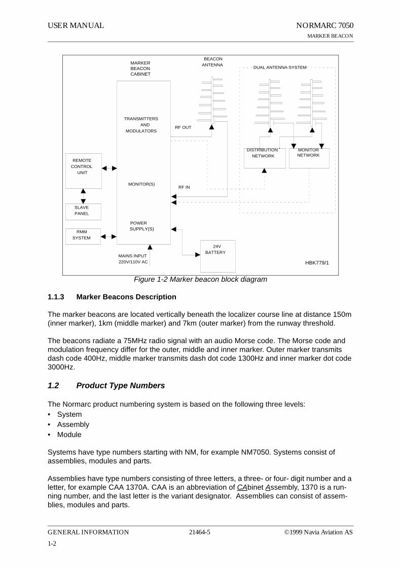
Figure 2-1 shows the front panel of the cabinet, with the control panel, on/off switch and local PC connection.
Figure 2-1 NM 7050 Front panel
Figure 2-2 shows the open cabinet in front view with indication of plug in board location.
24V DC MAINS
MARKER BEACON SYSTEM
MAIN
OFF
ON
TX TO AIR
LOCAL RS232
POWER
ON
OFF
LOCAL
REMOTE
MANUAL
AUTO
STBY
DISAGR
PARAM
MAINT
BATT
NORMAL
ON/OFF
CHANGEOVER
SERVICE
WARNING
ALARM
TX1
ESC PREV NEXT
PROTECTWRITE
TX1/TX2
TX2
ENTER
LC1377
HBK780/1
©1999 Navia Aviation AS 21464-5 Physical organisation
2-1

USER MANUAL NORMARC 7050MARKER BEACON
Figure 2-2 NM 7050 Module Location
Notice the location of the different plug in boards. It is essential for the MB to function, that the cards are placed in these locations. If your MB is configured with only one plugin board of each type, they must be placed in the number one locations. The backplane is however , marked with notifications of where each boards place is..
ΤThe electronic devices inside NM 7050 are sensitive to Electro Static Discharge(ESD). Please follow the instructions given in the preface of this manual to avoiddamage during servicing and transportation.
PS 1375 TX 1373 MO 1374 PB 1378CI 1376
AN
T I ST
AT
Antistatic socket
POW
ER S
UPP
LY 1
POW
ER S
UPP
LY 2
*)
TRAN
SMIT
TER
1
TRAN
SMIT
TER
2
MO
NIT
OR
1
MO
NIT
OR
2 **
)
*) Only used in dual power systems (NM 7050 B/D)**) Only used in dual monitor systems (NM 7050 C/D)
HBK781/1
2-2
21464-5Physical organisation ©1999 Navia Aviation AS

USER MANUALNORMARC 7050MARKER BEACON
3 System Description
3.1 Introduction / Overview
The system is housed in a compact cabinet. There are four models/configurations of the NM 7050.
Table3-1 Models / Configurations
As shown in Table 3-1, the beacon can have one or two monitor units and one or two power supply units. Figure 3-1 shows a block diagram of the MB system.
The monitor and transmitter control function is based on software. The system is based on modern technology with extensive Remote Monitoring and Maintenance capabilities, and very high reliability and integrity.
Variant Monitor Power SupplyNM7050A 1 1NM7050B 1 2NM7050C 2 1NM7050D 2 2
©1999 Navia Aviation AS 21464-5 System Description
3-1
USER MANUAL NORMARC 7050MARKER BEACON
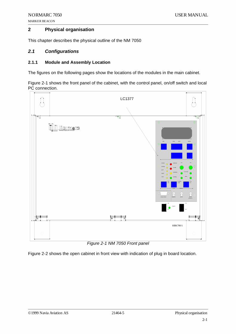
Figure 3-1 MB block diagram
3.2 Transmitters / Modulators
The NM7050 consists of two TX1373A transmitters. The main transmitter is connected to the antenna, while the standby transmitter is connected to dummy load. A failure in the main transmitter will cause an automatic change over to the standby transmitter.
The audio signals are generated in the LF circuitry mainly by a Field Programmable Gate Array (FPGA). A strap field selects Inner, Middle or Outer Marker settings.
An onboard oscillator generates a 75MHz carrier wave which is amplitude modulated with the
LF GENERATOR
RF OSCILLATOR
POWERAMPLIFIER
CHANGEOVER
LOCALCONTROL
TX1/TX2
ON/OFF
75 MHz
400 Hz
1.300 Hz
3.000 Hz
KEYBOARDDISPLAY
AD
CPU
NM7050 - MARKER BEACON
STATIONCONTROL
AD
CPU
MONITORINGMAINTENANCE +RMM INTERFACE
MONITOR RFFRONTEND MONITOR
BASEBAND+RF LEVEL
OPTIONAL MONITOR 2
REMOTECONTROL
SLAVEPANEL
LOCAL PC
REMOTE PC
RMM
POWERSUPPLY
CONNECTIONINTERFACE
TRANSMITTER 1
TRANSMITTER 2
MONITOR RFFRONTEND MONITOR
AC
DC
DC
DC
LINE+MODEM
MONITOR 1
OPTIONAL POWER
MO 1374
MO 1374
TX 1373
LC 1377
CI 1376
PS 1375
DUMMYLOAD
MAINS BATTERY SENSORS ETC.
BASEBAND+RF LEVEL
MAINTENANCE +RMM INTERFACE MONITORING
STATIONCONTROL
SPLITTER ONLY PRESENT IF TWO MONITORS
LF GENERATOR
RF OSCILLATOR
POWERAMPLIFIER
75 MHz
400 Hz
1.300 Hz
3.000 Hz
TX 1373
ON/OFF
MODULATION DEPTHOUTPUT RF LEVELKEYING NORMAL/OFF/CONT.STATUS
+20V+/-15V+5V
MONITOR 2DATA
LINE+MODEM
HBK782/1
RMM
3-2
21464-5System Description ©1999 Navia Aviation AS

USER MANUALNORMARC 7050MARKER BEACON
audio signal in the Power Amplifier (PA). The PA is capable of delivering up to 4W power at 97% depth of modulation.
Unwanted frequencies are removed by a lowpass filter after the PA.
3.3 Monitors / Transmitter Control
The marker beacon has one or two MO1374 monitor modules depending on model (Table 3-1).
The MO1374 is mainly a microprocessor based module. It contains the MB software and forms the basis of the monitor, station control, system maintenance handling and RMS user interface.
A detection of error in the transmitter signal causes change-over to the standby transmitter. Failure of the standby transmitter leads to an alarm and optional shutdown of the standby transmitter.
On a system with two monitor units, both must report error for alarm to be generated (2 of 2 voting). If the monitors disagree, the WARNING and DISAGR LEDs on the front panel is lit.
The MO1374 consists of two submodules:
The RF frontend receives a RF signal from the antenna (or recombining network for dual antenna system). It demodulates the signal into analogue values propotional to the RF power, the modulation depth and the morse code envelope. These parameters are digitized and monitored by the CPU section.
The CPU section includes an 80CI88 CPU, memory, communication ports and an AD con-verter system.
3.4 Power Systems
The marker beacon can have either one or two PS1375 power modules depending on model (Table 3-1). The PS1375 is 100W with 120V or 230V AC input voltage and +28V/3.5 A, +20/2.5A, ±12V/1.25A and 5V/6A DC output voltages. Outputs are short circuit protected. On the NM7050 B/D the two modules operate in parallel.
The 28V output is temperature compensated to ensure optimum battery charging. It gives 26.4V at 50°C and linearly increase to 29.6V at -30°C.
The backup battery is an external 24V battery. The battery gives a backup time of 6 hours, and have external charging possibilities for longer backup time. This battery is automatically brought into circuit on mains power failure. The charging time is approximately eight hours with one PS1375 and five hours with two PS1375.
3.5 Remote control system
The remote control unit is used in the tower or in the technical control room. It has indicators for operating status as well as detailed warnings and an aural alarm device with reset. It can control equipment on/off and change over, and has an Access Grant switch to allow/inhibit remote control from the RMM system.
©1999 Navia Aviation AS 21464-5 System Description
3-3

USER MANUAL NORMARC 7050MARKER BEACON
The Remote Control Unit is connected to the MB by one pair telephone cable.
3.6 Remote Maintenance Monitoring (RMM)
The NM7000 series has a built-in Remote Maintenance Monitoring system. This system con-sists of the RMS system, remote PC terminals with the RMM program installed, and the local keyboard/display. Figure 3-2 illustrates the RMM/RMS systems.
Figure 3-2 The NM 7050 RMM/RMS systems
The centre of the RMM system is a CPU with the RMS core program. The RMS collects mea-surements and diagnostic data, and makes them available to the user. The collected informa-tion allows easy and cost effective maintenance, fault finding and routine reporting. In addition, system settings are distributed and parameter readings are collected via the RMS/CPU.
External Personal Computers are used for a user friendly interface to the RMM system. The equipment has two serial output ports, typically used to connect a local PC and a connection to a central maintenance facility.
RMShardware
RMScoreprogram
Localmeasuringpoints
Maintenancedata bus
RMS data bus
Localparameterstorages
LocalKeyboard/Display
Modem
NM7050
RMS system
RMM system
LocalRemote
RMM program
Modem
programRMM
HBK783-1
3-4
21464-5System Description ©1999 Navia Aviation AS

USER MANUALNORMARC 7050MARKER BEACON
The local keyboard/display allows readings and controls through an LCD display and a seven-button keypad. This gives access to the RMM functionality without the need for a PC.
3.7 RMM Access
Access to the RMM system is controlled by multiple hardware and software access controls. One password is required for each access level, i.e. one password for level 1, two for level 2 and three for level 3. Optional hardware controls may inhibit writing in the upper access lev-els.
Access level 1• Readout of all the monitor values, warning and alarm limits.• Readout of all the maintenance values and warning limits.• Readout of all the delays.
Access level 2• TX1 and TX2 : morse normal, continuous or off.• TX1 and TX2 : test signals 50% depth of mod. and 50% RF level.• Diagnostics.
Access level 3• Settings of all the monitor warning and alarm limits.• Settings of all the maintenance warning limits.• Settings of all the delays.
3.8 Local Keyboard/Display Functions
Through a menu based interface all main commands, adjustments and monitor limits are accessible from the front panel keypad and LCD display. In addition a quick read function gives readout of all main monitor parameters at a glance.
3.9 Document structure
In Figure 3-3 the document structure is shown. The upper tree is the contents of the cabinet,
©1999 Navia Aviation AS 21464-5 System Description
3-5

USER MANUAL NORMARC 7050MARKER BEACON
while the lower tree is additional tower equipment.
Figure 3-3 Document structure NM 7050 Marker Beacon system
CAA1370ACabinet
Assembly
NM7050A-DMarkerBeacon
TX1373ATransmitter
MO1374AMonitor
PS1375APowerSupply
CI1376AConnection
Interface
PB1378APiggyBack
RC1241ARemoteControl
RF1242ARemoteFront
RCA124 0ARemoteControl
Assembly
LC1377ALocal
Control
SF1344ASlaveFront
MB1346/7AMotherboard
CA1348ACabinet
PS635BPower Supply
RFA1353RemoteFrame
Assembly
CH1385A/BCable
Harness
AdditionalTower
Equipment
HBK859/1
3-6
21464-5System Description ©1999 Navia Aviation AS

USER MANUALNORMARC 7050MARKER BEACON
4 Technical Specifications
NM 7050 Marker Beacon Cabinet.
4.1 Signal Requirements
4.1.1 Transmitter
4.1.2 Modulator
Frequency range 75 MHZ
Frequency tolerance ±0,005 %Output power range 0,005 – 4 W adjustable.
Fixed attenuator optional in lower rangeHarmonic radiation 2,5 UW maximumspurious radiation 25 UW maximumOUTPUT POWER STABILITY ±0.5DBTest function Preset adjustable RF level
MODULATION TYPE AMModulation alternatives
KEYED CONTINUOUS OFF
MODULATION FREQUENCY AND IDENTIFICATION
INNER MARKER 3000 HZ • Τ• Τ• Τ• Τ• Τ• Τ•MIDDLE MARKER 1300 HZ ΤΤ• ΤΤ ΤΤ•Outer marker 400 HZ ΤΤΤ ΤΤΤ
Modulation depth 95%adjustable range 45-97 %MAX. STEP SIZE 0,5 % Depth of Modulationstability ±4 % Depth of ModulationFrequency tolerance ±2,5 %Total harmonic dist. 8 %maximumKeying
Speed 125 MS/DOT APPROX.PAUSE TO DOT RATIO 1:1PAUSE TO DASH RATIO 1:3 dots/SEC
2 dashes/secTest function Preset adjustable Depth of Modulation,
normal, continous or no keying
©1999 Navia Aviation AS 21464-5
4-1
Technical Specifications

USER MANUAL NORMARC 7050MARKER BEACON
4.1.3 Monitoring
4.1.3.1 Alarm Functions
4.1.3.2 Monitor input levels
4.1.3.3 Monitor stability at nominal levels
4.1.3.4 Warning funktion
4.1.3.5 Protocols
4.1.4 Remote Control
RF power reduction 1,5-3 DB adjustableChange of modulation depth 50-70 % Depth of ModulationKeying absenceAlarm identification to automatic
transmitter change overSENDERUMSCHALTUNG 2-5 sec.
LINE BREAK MB - Remote Control (DISABLE OPTIONAL) Standby alarm identification to transmitter shutdown shall be configurable.
Adjustment range, nominal level +1 TO -25 DBM (strap settings for IM, MM and OM sensitivity)
RF POWER VALUES ±0,5 DBMODULATION DEPTH VALUES ±1,0 % Depth of Modulation
@ 10 – 30 ºC±3,0 % Depth of Modulation
@ full temp. range±2,0 % Depth of Modulation
variation for 3dB RF reduction @ 10-30°C.
RF POWER REDUCTION 40-75 % of alarm limitChange of modulation depth 40-75 % of alarm limitMaintenance parameter outside limitsMains failure
Monitor 1 to monitor 2 communication SERIAL DATA PROTOCOL (not RS 232)RMM DATA PROTOCOL RS232
Either
4-2
21464-5Technical Specifications ©1999 Navia Aviation AS

USER MANUALNORMARC 7050MARKER BEACON
4.2 Environmental characteristics
4.3 EMV-charakteristics
4.4 Mechanical characteristics
Data Transmission Medium 2-wire line, 600 ohmData modulation SERIAL, FSKTransmitter level -10 DBM ± 2 DBReceiver dynamic range -10 DBM... -34 DBM OR RS232
orRS-232 interface in both Marker Beacon and remote control
Operating temperature -40 TO +55 ºC(main cabinet except display)
-10 TO +55 ºC(display, remote con-trol and slave panel)
Storage temperature -40 TO +60 ºCHUMIDITY 95% TO +35 °C
DECREASING LINEARLY TO 60% AT +55 °C
VIBRATION 0.15MM OR 19.6M/S2 (2G)VERTICAL,10Hz to 500Hz
GENERAL SPECIFICATIONS FOR EMC ETS 300 339EN50081-1 (emmission)EN50082-2 (immunity)EN61000-3-2 (harmonic current emmission)EN61000-3-3 (voltage fluctuations and flicker)
SPURIOUS AND HARMONICS CISPR 22SAFETY EN 60950
Dimensions (hxwxd):MB CABINET 267 X 450 X 343 MM
REMOTE CONTROL 71 X 132 X 200 MM
SLAVE PANELS 51 X 132 X 200 MM
The MB rack is wall mounted. The remote control and slave panel fit a 19" shelf.
©1999 Navia Aviation AS 21464-5
4-3
Technical Specifications

USER MANUAL NORMARC 7050MARKER BEACON
4.5 Power supply
OPERATING VOLTAGE:MAIN SUPPLY 230 V +15 %/-20 %, 45-65 HZ,
OR 120 V +15 %/-20 %, 45-65 HZ
STAND-BY BATTERY 24 V DC NOMINAL,float charged by the main Supply. The battery is able to use an external charger.The equipment is able to operate without battery.
POWER CONSUMPTION:MB CABINET: < 50 WREMOTE CONTROL < 5 W
BATTERY CHARGER ADAPTED TO 5 HOURS (NM 7050 B/D) or 8 hours (NM 7050 A/C) charging time to 90% battery capacity for a battery giving 6 hours operation. External battery charges may be connected for longer operation, and shorter charging time.
4-4
21464-5Technical Specifications ©1999 Navia Aviation AS
USER MANUALNORMARC 7050MARKER BEACON
5 Electrical installation
5.1 Marker beacon cabinet
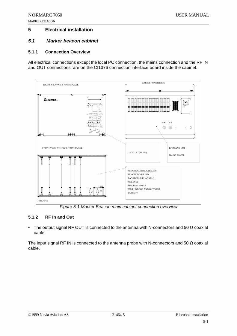
5.1.1 Connection Overview
All electrical connections except the local PC connection, the mains connection and the RF IN and OUT connections are on the CI1376 connection interface board inside the cabinet.
Figure 5-1 Marker Beacon main cabinet connection overview
5.1.2 RF In and Out
• The output signal RF OUT is connected to the antenna with N-connectors and 50 Ω coaxial cable.
The input signal RF IN is connected to the antenna probe with N-connectors and 50 Ω coaxial cable.
GN
D LN
RF INRF OUT
ON ON
OFF24V DC
OFFPOW ER
MAINS
ON/OFF
LOCAL RS232
DISAGR
STBY
MAINT
BATT
PARAM
REMOTE AUTO
LOCAL MANUAL
CHANGEOVER
PROTECTW RITE
TX1/TX2
MAIN
TX TO AIR
NORMAL
W ARNING
ALARM
SERVICETX1 TX2
MARKER BEACON SYSTEM
ESC PREV NEXT ENTER
CABINET UNDERSIDEFRONT VIEW WITH FRONT PLATE
FRONT VIEW WITHOUT FRONT PLATE RF IN AND OUT
MAINS POWERLOCAL PC (RS 232)
REMOTE CONTROL (RS 232)REMOTE PC (RS 232)3 ANALOGUE CHANNELSAC LEVEL4 DIGITAL PORTSTEMP. INDOOR AND OUTDOORBATTERY
AN
TISTAT
HBK784/1
©1999 Navia Aviation AS 21464-5 Electrical installation
5-1

USER MANUAL NORMARC 7050MARKER BEACON
.
Figure 5-2 RF cable connection
5.1.3 Battery
The external backup battery is connected between BATT GND (-) and BATT +24V (+) on the connector marked BATTERY on CI 1376.
A 16Ah battery gives approximately six hours backup time with 5-8 hours charging time dependent on model. For longer backup time an external charger is required to be able to charge the battery within a reasonable time. An external battery protection circuit (like Nor-marcs BP 543) has to be connected between the EXT. CHARGER (+) and BATT GND (-) input. In addition MAINS directly on NM 7050 has to be disconnected. Figure 5-4 shows the connec-tions schematically.
RF OUT RF IN
HBK785/1
5-2
21464-5Electrical installation ©1999 Navia Aviation AS

USER MANUALNORMARC 7050MARKER BEACON
Figure 5-3 Battery connection
Figure 5-4 External charger connection
5.1.4 Mains
The mains power cable connections are underneath the cabinet. They are covered by a alu-minium plate fastened with four screws. The cable itself is threaded through the cable gland and the three wires are connected to the terminals N, L and GND shown below in figure 6-4.
CI 1376REMOTE
CONTROLLINE
TEMPOUTDOOR
TEMPINDOOR
AC LEVEL ANA CHA1 ANA CHA2 ANA CHA3
DIG PORT A DIG PORT B DIG PORT C DIG PORT D
BATT GND
EXT CHARGE
BATT +24V
1
2
3
BATTERY
BATT GND
EXT CHARGE
BATT +24V
BATTERY
HBK786/1
AC
DC
BP 543
BATTERYEXT.CHARGE
BATT +24VBATT GND
MAINS
EXTERNALCHARGER
BATTERYPROTECTION
NM 7050
HBK863/1
©1999 Navia Aviation AS 21464-5 Electrical installation
5-3

USER MANUAL NORMARC 7050MARKER BEACON
Figure 5-5 Power connection
5.1.5 Modem Power
A DC powered modem or other external equipment designed for 22V-27V DC can be con-nected to the terminal block marked MODEM POWER. Maximum current consumption should be 800 mA.
MAINS POWER
GN
D LN
GROUND CABLE CONNECTIONHBK787/1
5-4
21464-5Electrical installation ©1999 Navia Aviation AS

USER MANUALNORMARC 7050MARKER BEACON
Figure 5-6 Modem Power
5.1.6 Remote Control
The remote line and remote control is connected to the CI 1376 connection interface board as illustrated in Figure 5-7. • FSK_[A,B] is the modem line pair.• GND is main cabinet ground
A suitable female connector for the remote line is Weidemüller BLZ-5.08/4 or equivalent.
Alternatively the remote control connection is done with a RS 232 interface. The mode is con-figured on MO 1374, refer to 7.2.3.
Note: The position of RXD and TXD is interchanged from the normal RS-232 layout in the Remote Control connector. Therefore a special cable must be used for connection to external equipment.
CI 1376REMOTE
CONTROLLINE
TEMPOUTDOOR
TEMPINDOOR
AC LEVEL ANA CHA1 ANA CHA2 ANA CHA3
DIG PORT A DIG PORT B DIG PORT C DIG PORT D
-(GND)123
BATT GND
EXT CHARGE
BATT +24V
BATTERY
-
+
+ (+24V DC)
MODEM POWER
MODEM POWER
H1116/1
©1999 Navia Aviation AS 21464-5 Electrical installation
5-5

USER MANUAL NORMARC 7050MARKER BEACON
Figure 5-7 Remote control connection
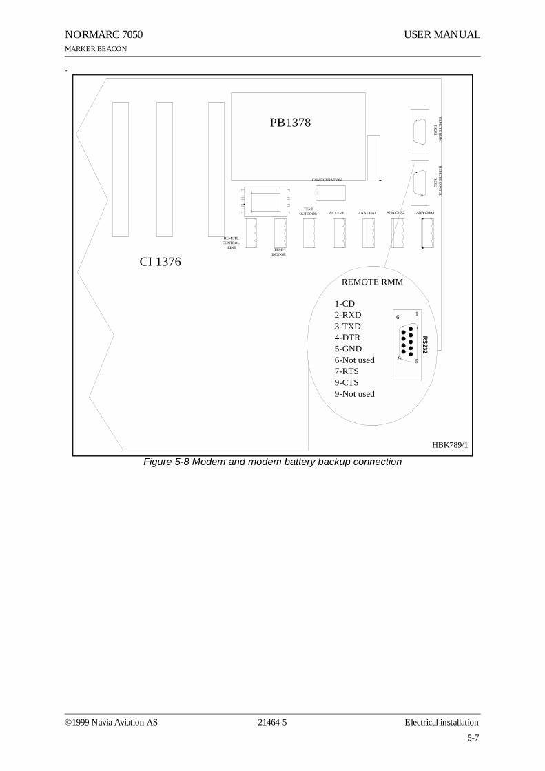
5.1.7 PC and Modem
Modem connections for remote PC are the standard pin out RS232, 9 pins DSUB connector on the CI1376 connection interface board marked remote-rmm as illustrated in Figure 5-8.
For local PC connection use the RS232 on front panel Figure 5-9.
CI 1376
PB 1378
REMOTECONTROL
LINE
TEMPOUTDOOR
TEMPINDOOR
AC LEVEL ANA CHA1 ANA CHA2 ANA CHA3
REM
OTE R
MM
RS232
REM
OTE C
ON
TOL
RS232
CONFIGURATION
1 - GND
2 - RC_LINE B
4 - Not used
1 - Not used
3 - RXD2 - TXD
4 - Not used5 - GND6 - Not used7 - Not used8 - Not used9 - Not used
REMOTECONTROL
REMOTECONTROL
LINE
RS
-232
HBK788/3
2 - RC_LINE A
5-6
21464-5Electrical installation ©1999 Navia Aviation AS
USER MANUALNORMARC 7050MARKER BEACON
.
Figure 5-8 Modem and modem battery backup connection
CI 1376
PB1378
REMOTECONTROL
LINE
TEMPOUTDOOR
TEMPINDOOR
AC LEVEL ANA CHA1 ANA CHA2 ANA CHA3
REMO
TE RMM
RS232
REM
OTE CO
NTO
LR
S232
CONFIGURATION
DIG PORT A DIG PORT B DIG PORT C DIG PORT D
1-CD2-RXD3-TXD4-DTR5-GND6-Not used7-RTS9-CTS9-Not used
REMOTE RMM
6 1
9 5
HBK789/1
©1999 Navia Aviation AS 21464-5 Electrical installation
5-7

USER MANUAL NORMARC 7050MARKER BEACON
Figure 5-9 Local PC RS232 connection
5.1.8 Analogue Inputs
The analogue inputs are connected to the CI1376 connection interface board as illustrated in Figure 5-10.
The inputs are:• Analogue Channel 1-3 - three differential DC analogue inputs, P (pin-1) is the positive and
N (pin-3) is the negative terminal, and pin 2 is GND.Maximum voltage: ±15VInput impedance: 10kΩ
• Temp Indoor and Outdoor - temperature measurement inputs with interface to an LM35 temperature sensor.
Maximum voltage: ±15VInput impedance: 10kΩ
• AC Level - AC level measurement input. Intended for use with a battery eliminator to moni-tor the mains voltage.
Maximum voltage: 24Vpp
1 - Not used2 - RXD3 - TXD4 - Not used5 - GND6 - Not used7 - RTS8 - CTS9 - Not used
HBK790-1
5-8
21464-5Electrical installation ©1999 Navia Aviation AS

USER MANUALNORMARC 7050MARKER BEACON
Input impedance: 10 kΩ
Figure 5-10 Analogue input connections
5.1.9 Digital Inputs and Outputs
Eight bi-directional digital channels (numbered 0-7) are sited on the CI1376 connection inter-face board as illustrated in Figure 5-11.
Logical levels: TTLInput impedance: 560Ω.
A suitable female connector is Weidemüller BLZ-5.08/4 or equivalent.
CI 1376
PB 1378
REMOTECONTROL
LINE
TEMPOUTDOOR
TEMPINDOOR
AC LEVEL ANA CHA1 ANA CHA2 ANA CHA3
REM
OTE R
MM
RS232
RE
MO
TE CO
NTO
L
RS232
CONFIGURATION
DIG PORT A DIG PORT B DIG PORT C DIG PORT D
1-ANLG*P2-GND3-ANLG*N4-Not used
ANALOGUECHANNEL 1-3
1-VACP2-GND3-VACN4-Not used
AC LEVEL
1-VDD2-T*DOOR3-GND4-Not used
TEMP *
V+VtempGND
LM 35Bottom view
HBK791/1
©1999 Navia Aviation AS 21464-5 Electrical installation
5-9

USER MANUAL NORMARC 7050MARKER BEACON
Figure 5-11 Digital input/output connections
5.1.10 Power for Modem or other external devices
A DC powered modem or other external equipment designed for 22V - 27V DC can be con-nected to the screw terminal J30. Maximum current consumption should be 0.8A.
The terminal marked OUT+ is 22V - 27V DC, OUT- is ground
5.1.11 Remote Control Interface (MB rack)
The transmission medium (telephone line (FSK modem) or RS 232) to the Remote Control can be selected by plugs and link straps S700 and S701 on the MO1374 module:
1- DIGIN 1
2- GND
3- DIGIN 0
4-GND
1- DIGIN 3
2- GND
3- DIGIN 2
4-GND
1- DIGIN 5
2- GND
3- DIGIN 4
4-GND
1- DIGOUT 0
2- GND
3- DIGOUT 1
4-GND
DIGITAL PORTSA B C D
CI 1376
PB 1378
REMOTECONTROL
LINE
TEMPOUTDOOR
TEMPINDOOR
AC LEVEL ANA CHA1 ANA CHA2 ANA CHA3
RE
MO
TE R
MM
RS
232R
EMO
TE C
ON
TOL
RS
232
CONFIGURATION
DIG PORT A DIG PORT B DIG PORT C DIG PORT D
HBK792/1
5-10
21464-5Electrical installation ©1999 Navia Aviation AS
USER MANUALNORMARC 7050MARKER BEACON
5.2 Tower equipment
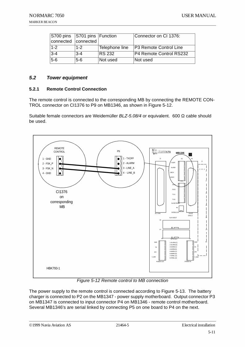
5.2.1 Remote Control Connection
The remote control is connected to the corresponding MB by connecting the REMOTE CON-TROL connector on CI1376 to P9 on MB1346, as shown in Figure 5-12.
Suitable female connectors are Weidemüller BLZ-5.08/4 or equivalent. 600 Ω cable should be used.
Figure 5-12 Remote control to MB connection
The power supply to the remote control is connected according to Figure 5-13. The battery charger is connected to P2 on the MB1347 - power supply motherboard. Output connector P3 on MB1347 is connected to input connector P4 on MB1346 - remote control motherboard. Several MB1346's are serial linked by connecting P5 on one board to P4 on the next.
S700 pins connected
S701 pins connected
Function Connector on CI 1376:
1-2 1-2 Telephone line P3 Remote Control Line3-4 3-4 RS 232 P4 Remote Control RS2325-6 5-6 Not used Not used
REMOTECONTROL
1 - GND
2 - FSK_P
3 - FSK_N
4 - GND
J2 P3
P6
P7
P4P5
P9
P10
P8
OPTO OUT
2-ALARM (E)1-ALARM (C)
4-NORM (E)5-WARN (C)6-WARN (E)7-STBAL (C)8-STBAL (E)
3-NORM (C)
GND
5V
24V
V_DIM
GND
5V
24V
V_DIM
POWER OUT POWER IN
AUX IN/OUT
SLAVEDIRECT
INTERLOCK
TXOFF
ALARM
LINE A
LINE B
RX A
RX B
TX A
TX B
SLAVE RS485
J1
ABC1
5
30
20
25
15
10
ALT.LINK
MB1346P9
1 - TXOFF
2 - ALARM
3 - LINE_A
4 - LINE_B
CI1376 on
corresponding MB
HBK793-1
©1999 Navia Aviation AS 21464-5 Electrical installation
5-11
USER MANUAL NORMARC 7050MARKER BEACON
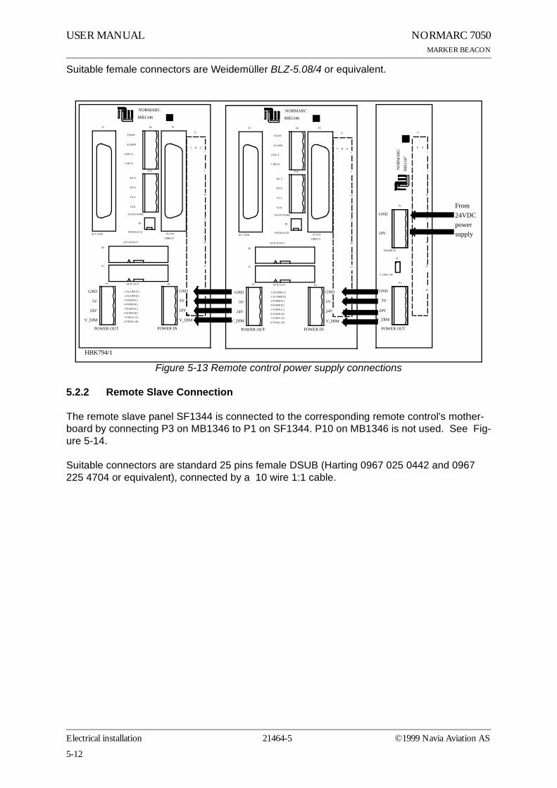
Suitable female connectors are Weidemüller BLZ-5.08/4 or equivalent.
Figure 5-13 Remote control power supply connections
5.2.2 Remote Slave Connection
The remote slave panel SF1344 is connected to the corresponding remote control's mother-board by connecting P3 on MB1346 to P1 on SF1344. P10 on MB1346 is not used. See Fig-ure 5-14.
Suitable connectors are standard 25 pins female DSUB (Harting 0967 025 0442 and 0967 225 4704 or equivalent), connected by a 10 wire 1:1 cable.
J2 P3
P6
P7
P4P5
P9
P10
P8
NORMARC
OPTO OUT
2-ALARM (E)
1-ALARM (C)
4-NORM (E)
5-WARN (C)
6-WARN (E)
7-STBAL (C)
8-STBAL (E)
3-NORM (C)
GND
5V
24V
V_DIM
GND
5V
24V
V_DIM
POWER OUT POWER IN
AUX IN/OUT
SLAVE
DIRECT
INTERLOCK
TXOFF
ALARM
LINE A
LINE B
RX A
RX B
TX A
TX B
SLAVE RS485
J1
ABC1
5
30
20
25
15
10
ALT.LINK
MB1346
P2
P3
S1
GND
24V
POWER IN
GND
5V
24V
V_DIM
POWER OUT
V_DIM=24V
MB
1347
NO
RM
AR
C
30
25
20
15
10
5
1
AB
J1
J2 P3
P6
P7
P4P5
P9
P10
P8
NORMARC
OPTO OUT
2-ALARM (E)
1-ALARM (C)
4-NORM (E)
5-WARN (C)
6-WARN (E)7-STBAL (C)
8-STBAL (E)
3-NORM (C)
GND
5V
24V
V_DIM
GND
5V
24V
V_DIM
POWER OUT POWER IN
AUX IN/OUT
SLAVE
DIRECT
INTERLOCK
TXOFF
ALARM
LINE A
LINE B
RX A
RX B
TX A
TX B
SLAVE RS485
J1
ABC1
5
30
20
25
15
10
ALT.LINK
MB1346
From 24VDCpowersupply
HBK794/1
5-12
21464-5Electrical installation ©1999 Navia Aviation AS

USER MANUALNORMARC 7050MARKER BEACON
Figure 5-14 Remote slave connection
J2 P3
P6
P7
P4P5
P9
P10
P8
NORMARC
OPTO OUT
2-ALARM (E)
1-ALARM (C)
4-NORM (E)
5-WARN (C)
6-WARN (E)
7-STBAL (C)8-STBAL (E)
3-NORM (C)
GND
5V
24V
V_DIM
GND
5V
24V
V_DIM
POWER OUT POWER IN
AUX IN/OUT
SLAVE
DIRECT
INTERLOCK
TXOFF
ALARM
LINE A
LINE B
RX A
RX B
TX A
TX B
SLAVE RS485
J1
ABC1
5
30
20
25
15
10
ALT.LINK
MB1346
1:1To P1 onSF1344
1
13
14
25
1 - GND2 - ALARM3 - WARNING4 - NORMAL7 - GND15 - V24P19 - ON_OFF21 - SILENCE23 - INTERLOCK (if used)25 - BUZZER
HBK795/1
©1999 Navia Aviation AS 21464-5 Electrical installation
5-13

USER MANUAL NORMARC 7050MARKER BEACON
5-14
21464-5Electrical installation ©1999 Navia Aviation AS

USER MANUALNORMARC 7050MARKER BEACON
6 Antenna
Normarc supplies single and dual antennas, NM 3561 and NM 3562 respectively. The single antenna may be used for inner, middle and outer marker, while the dual antenna is specially designed for outer markers. The advantage of the dual antenna is a lower spread in FLYING THROUGH TIME inside the localizer coverage area. In addition to two antenna elements, the monitor and distribution network DI 726 is included in NM 3562.
Figure 6-1 Antenna block diagram
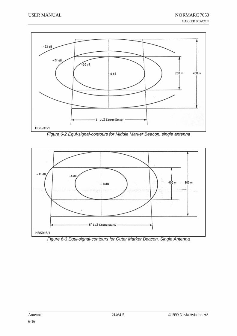
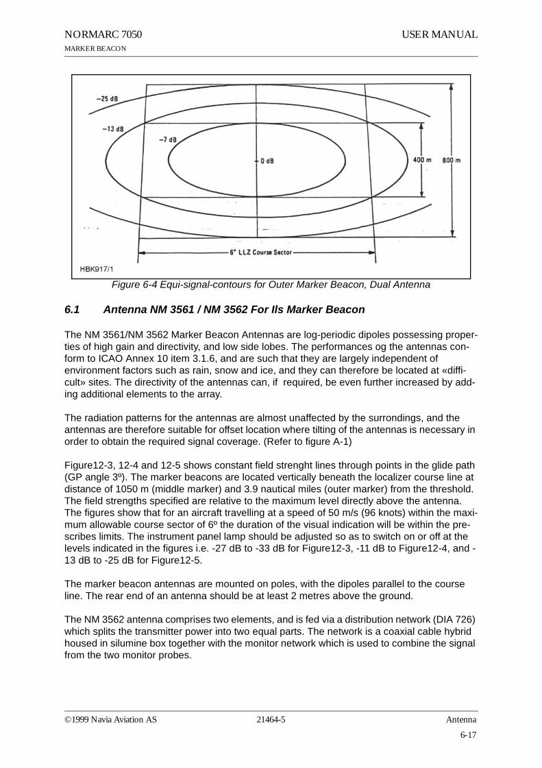
Figure6-2 shows the field strength of the radiated signal directly above the middle marker antenna. Figure6-3 and Figure6-4 illustrate the field strength above the outer marker antenna, using single and dual antenna, respectively. The localizer course sector is scetched. Along an elliptical curve, the field strength is constant. If you look at the diagrams as ordinary geographical maps, you will see that the dual antenna "field-strength-mountain" is steaper and more stretched sideways than the single antenna "mountain". This corresponds to a sharper on/off response on the aircraft's marker beacon instruments.
SINGLE ANTENNA SYSTEM
NETWORKDI 726
RF OUT RF IN
DUAL ANTENNA SYSTEM
RF OUT RF IN
5050
HBK914-1
©1999 Navia Aviation AS 21464-5 Antenna
6-15
USER MANUAL NORMARC 7050MARKER BEACON
Figure 6-2 Equi-signal-contours for Middle Marker Beacon, single antenna
Figure 6-3 Equi-signal-contours for Outer Marker Beacon, Single Antenna
6-16
21464-5Antenna ©1999 Navia Aviation AS
USER MANUALNORMARC 7050MARKER BEACON
Figure 6-4 Equi-signal-contours for Outer Marker Beacon, Dual Antenna
6.1 Antenna NM 3561 / NM 3562 For Ils Marker Beacon
The NM 3561/NM 3562 Marker Beacon Antennas are log-periodic dipoles possessing proper-ties of high gain and directivity, and low side lobes. The performances og the antennas con-form to ICAO Annex 10 item 3.1.6, and are such that they are largely independent of environment factors such as rain, snow and ice, and they can therefore be located at «diffi-cult» sites. The directivity of the antennas can, if required, be even further increased by add-ing additional elements to the array.
The radiation patterns for the antennas are almost unaffected by the surrondings, and the antennas are therefore suitable for offset location where tilting of the antennas is necessary in order to obtain the required signal coverage. (Refer to figure A-1)
Figure12-3, 12-4 and 12-5 shows constant field strenght lines through points in the glide path (GP angle 3º). The marker beacons are located vertically beneath the localizer course line at distance of 1050 m (middle marker) and 3.9 nautical miles (outer marker) from the threshold. The field strengths specified are relative to the maximum level directly above the antenna. The figures show that for an aircraft travelling at a speed of 50 m/s (96 knots) within the maxi-mum allowable course sector of 6º the duration of the visual indication will be within the pre-scribes limits. The instrument panel lamp should be adjusted so as to switch on or off at the levels indicated in the figures i.e. -27 dB to -33 dB for Figure12-3, -11 dB to Figure12-4, and -13 dB to -25 dB for Figure12-5.
The marker beacon antennas are mounted on poles, with the dipoles parallel to the course line. The rear end of an antenna should be at least 2 metres above the ground.
The NM 3562 antenna comprises two elements, and is fed via a distribution network (DIA 726) which splits the transmitter power into two equal parts. The network is a coaxial cable hybrid housed in silumine box together with the monitor network which is used to combine the signal from the two monitor probes.
©1999 Navia Aviation AS 21464-5 Antenna
6-17

USER MANUAL NORMARC 7050MARKER BEACON
Specifications: NM 3561: NM 3562:
Antenna construction 1 LPDA 2 LPDAs
Frequency 75 MHz 75 MHz
Gain 8,2 dB 11 dB
VSWR 50 Ohm 1,2 dB 1,2 dB
Required RF power 0,5W 0,4W
Dimensions 3,3 x 2,2 m 3,3 x 4,7 m
Weight 50 kg 110 kg
Mounting Both types: 2.2 metres above ground
Temperature Both types: -40ºC to +70ºC
Wind velocity Both types: up to 180 km/h
6-18
21464-5Antenna ©1999 Navia Aviation AS


![1 No HSYNC Jitter Anomaly Programmable Using IControl I2C Slave I/F For DDC 1.8-V Regulators With Bypass Capacitors PLL TX2± TX1± TX0± TXC± TFADJ IDCK± DATA[23:0] DE VSYNC HSYNC](https://img.dokumen.tips/doc/110x75/6090a52d644c1728ea591fa2/1-no-hsync-jitter-anomaly-programmable-using-i-control-i2c-slave-if-for-ddc-18-v.jpg)