Embed Size (px)
Citation preview

Normal Operating Parameters • Maintenance Schedule • Common ProblemsNormal Operating Parameters • Maintenance Schedule • Common Problems
ClearWater Tech, LLC.ClearWater Tech, LLC.Service & Maintenance SeminarService & Maintenance Seminar

• • Ambient temperature range : 20º F to 85º FAmbient temperature range : 20º F to 85º F - If temperature constantly exceeds 100º F, additional air cooling must be provided
• • Relative Humidity : 75% max.Relative Humidity : 75% max.
• • Unit energized - constantUnit energized - constant (plugged into a non-switched outlet)(plugged into a non-switched outlet)
• • Air flow through dryer : 10 hours max.Air flow through dryer : 10 hours max.
• • SCFH - determined by ozone SCFH - determined by ozone generator usedgenerator used
*Equipment: AD40, CD10/AD, M15/AD, CD15/AD*Equipment: AD40, CD10/AD, M15/AD, CD15/AD
Normal Operating ParametersNormal Operating ParametersAir Preparation - Heat Regenerative Dry AirAir Preparation - Heat Regenerative Dry Air

Normal Operating ParametersNormal Operating Parameters Air Preparation - Oxygen ConcentratorAir Preparation - Oxygen Concentrator
Ambient Temperature range : Ambient Temperature range : 20ºF to 85º F20ºF to 85º F
Relative Humidity :Relative Humidity : 90% max.90% max. SCFH - determined by ozone SCFH - determined by ozone generator used. Set to atmospheric generator used. Set to atmospheric pressurepressure
Main power - switch(es) must be Main power - switch(es) must be on when vacuum is drawn on systemon when vacuum is drawn on system
(if so equipped)(if so equipped)
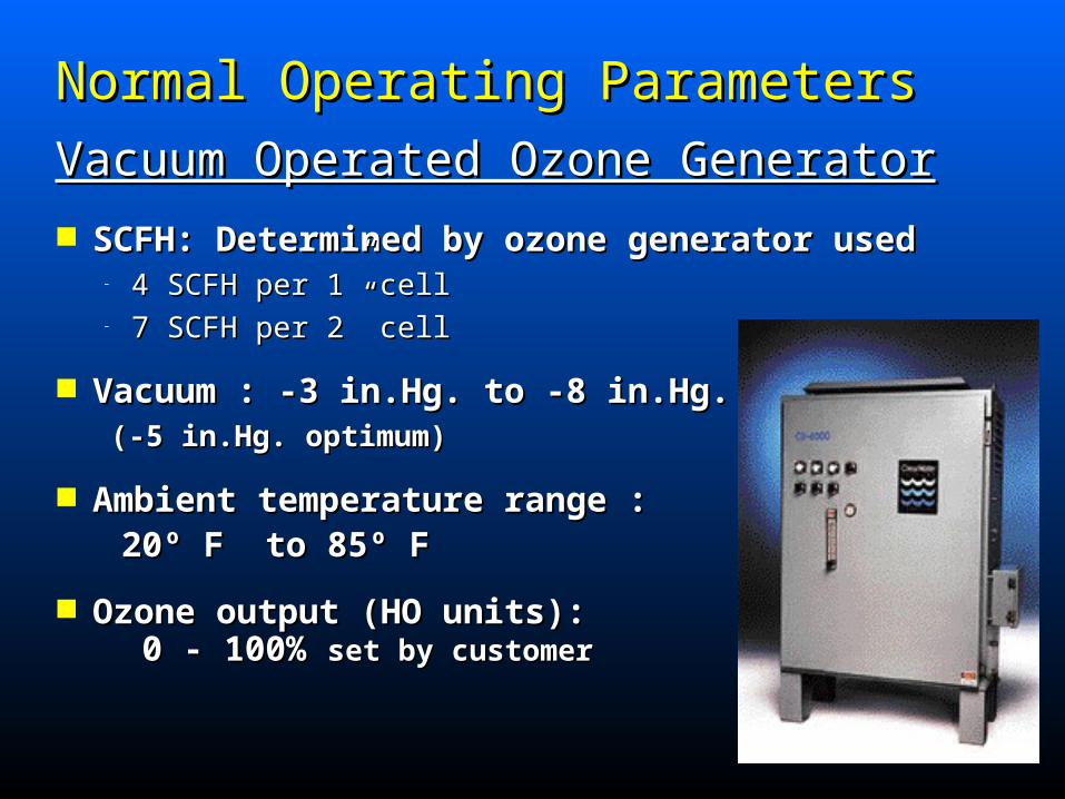
Normal Operating ParametersNormal Operating Parameters Vacuum Operated Ozone GeneratorVacuum Operated Ozone Generator
SCFH: Determined by ozone generator usedSCFH: Determined by ozone generator used– 4 SCFH per 1” cell4 SCFH per 1” cell– 7 SCFH per 2” cell7 SCFH per 2” cell
Vacuum : -3 in.Hg. to -8 in.Hg. Vacuum : -3 in.Hg. to -8 in.Hg. (-5 in.Hg. optimum)(-5 in.Hg. optimum)
Ambient temperature range : Ambient temperature range : 20º F to 85º F20º F to 85º F
Ozone output (HO units): Ozone output (HO units): 0 - 100% 0 - 100% set by customerset by customer

Normal Operating ParametersNormal Operating Parameters
Pressure Operated Ozone GeneratorPressure Operated Ozone Generator SCFH: Determined by ozone generator usedSCFH: Determined by ozone generator used
– 6 SCFH per cell6 SCFH per cell
Pressure : 9 to 12 psi (10 psi optimum) Pressure : 9 to 12 psi (10 psi optimum)
Ambient temperature range : Ambient temperature range : 20º F to 85º F20º F to 85º F
Ozone output:Ozone output: 0 - 100% set by customer0 - 100% set by customer

Daily ProceduresDaily Procedures1.1. Air Preparation Air Preparation
– Indicator Cartridge - inspectIndicator Cartridge - inspect
desiccant (blue & white)desiccant (blue & white)– SCFH - Standard Cubic Feet Per HourSCFH - Standard Cubic Feet Per Hour
NOTE: Amount will be less if reading is not at NOTE: Amount will be less if reading is not at atmospheric pressure.atmospheric pressure.
2.2. Ozone Generator Ozone Generator– Indicator lights - main power & operation indicators– SCFH - Standard Cubic Feet Per Hour– Vacuum -3in.Hg. To -8in. Hg. (-5in.Hg. optimum)– Pressure - 9 to 12 psi (10 psi optimum). NOTE: For NOTE: For pressure operated ozone generators only.pressure operated ozone generators only.
Maintenance Schedule Maintenance Schedule
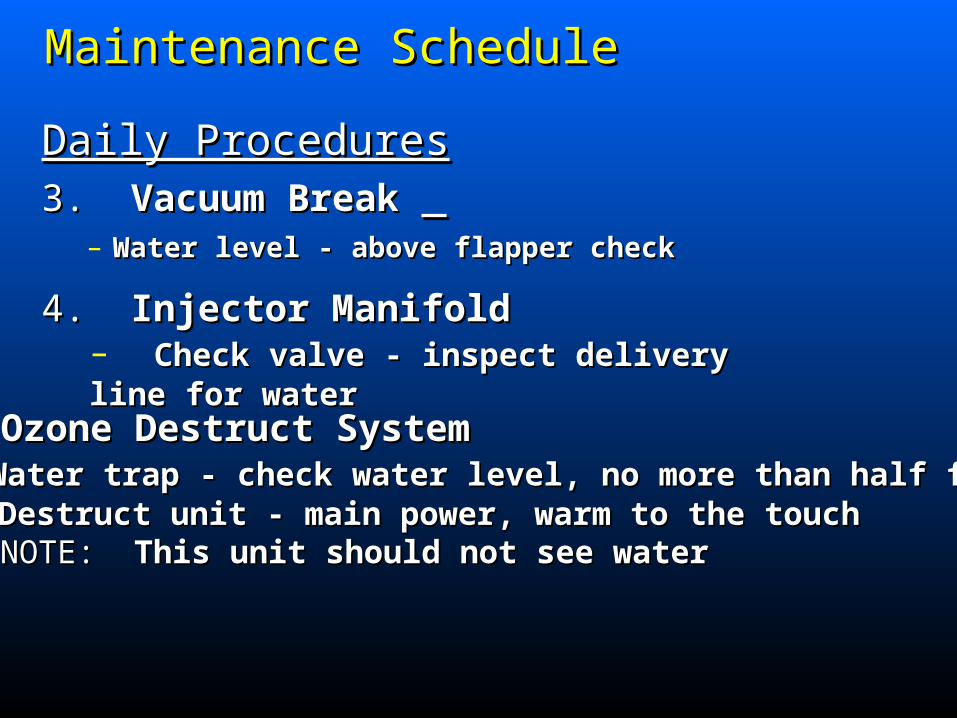
Daily ProceduresDaily Procedures3.3. Vacuum Break Vacuum Break
– Water level - above flapper checkWater level - above flapper check
4.4. Injector Manifold Injector Manifold– Check valve - inspect delivery line for water Check valve - inspect delivery line for water
5.5. Ozone Destruct System Ozone Destruct System– Water trap - check water level, no more than half fullWater trap - check water level, no more than half full– Destruct unit - main power, warm to the touchDestruct unit - main power, warm to the touch NOTE:NOTE: This unit should not see water This unit should not see water
Maintenance ScheduleMaintenance Schedule

Maintenance Schedule Maintenance Schedule Monthly ProceduresMonthly Procedures
2.2. Ozone Generator Ozone Generator– Drive module power - check L.E.D.’sDrive module power - check L.E.D.’s– Cooling fan operationCooling fan operation– Cooling fan filters - cleanCooling fan filters - clean
3.3. Booster Pump(s) Booster Pump(s)– Strainer baskets - clean
1.1. Air Preparation Air Preparation– Cooling fan operationCooling fan operation– Enclosure Filter(s) - cleanEnclosure Filter(s) - clean
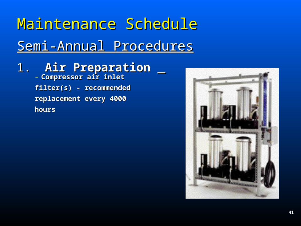
Maintenance Schedule Maintenance Schedule Semi-Annual ProceduresSemi-Annual Procedures
1.1. Air Preparation Air Preparation – Compressor air inlet Compressor air inlet
filter(s) - recommended filter(s) - recommended
replacement every 4000 replacement every 4000
hourshours
41

Maintenance Schedule Maintenance Schedule
Annual ProceduresAnnual Procedures
1.1. Air Preparation Air Preparation– Enclosure filter(s) - replaceEnclosure filter(s) - replace– Compressors - recommended rebuild Compressors - recommended rebuild every 5,000-12,000 hoursevery 5,000-12,000 hours
2.2. Ozone Generator Ozone Generator– Cooling fan filter(s) - replace– Inline filter - replace (cabinets in filter bowl)– Solenoid valve(s) - rebuild (cabinets only)– Reaction chambers - clean, rebuild as required

Maintenance Schedule Maintenance Schedule Annual ProceduresAnnual Procedures3.3. Vacuum Break Vacuum Break
– Clean - disconnect & rinse thoroughlyClean - disconnect & rinse thoroughly
4.4. Injector Manifold Injector Manifold
– Check valve- replaceCheck valve- replace
5.5. Contact Vessels Contact Vessels– Column (only) - clean diffuser slots, rinse thoroughly, replace gasket
6.6. Ozone Destruct System Ozone Destruct System– Off gas vent - clean, soak in 50/50 solution of water and muriatic acid for 24 hours.– Ozone destruct - replace catalyst (as required)

Common ProblemsCommon Problems
Air Preparation - Heat RegenerativeAir Preparation - Heat Regenerative– Unit not supplied continuous powerUnit not supplied continuous power– Excessive air flowExcessive air flow– Extreme environmental conditions - humidity, Extreme environmental conditions - humidity, ambient temperatureambient temperature– Indicators desiccant has changed to white & pink - Indicators desiccant has changed to white & pink - moisture has entered air prep. systemmoisture has entered air prep. system
Air Preparation - Oxygen ConcentratorAir Preparation - Oxygen Concentrator– Main power switch bring turned “OFF” duringMain power switch bring turned “OFF” during normal operationnormal operation

Vacuum Operated Ozone GeneratorVacuum Operated Ozone Generator
– Unit does not stay on - insufficient vacuumUnit does not stay on - insufficient vacuum
– Low Vacuum - hydraulic/pneumatics out of adjustment,Low Vacuum - hydraulic/pneumatics out of adjustment, hydraulic back pressure, no water in vacuum breakhydraulic back pressure, no water in vacuum break
– High Vacuum - change in hydraulicsHigh Vacuum - change in hydraulics
– Unit Flooded - Defective check valve, instal vacuumUnit Flooded - Defective check valve, instal vacuum breakbreak
– Low air flow/no air flow - air leak, check air prepLow air flow/no air flow - air leak, check air prep systemsystem
Common ProblemsCommon Problems

Common ProblemsCommon Problems
Pressure Operated Ozone GeneratorPressure Operated Ozone Generator
– Unit does not stay on - insufficient pressureUnit does not stay on - insufficient pressure
– Insufficent pressure - adjust needle valve, check Insufficent pressure - adjust needle valve, check for leaksfor leaks
– Low vacuum at Venturi - hydraulics out of adjustmentLow vacuum at Venturi - hydraulics out of adjustment
– High vacuum at Venturi - change in hydraulicsHigh vacuum at Venturi - change in hydraulics
– Unit flooded - defective check valve install vacuum Unit flooded - defective check valve install vacuum breakbreak

Common ProblemsCommon Problems
Ozone Injecting and ContactingOzone Injecting and Contacting
– Water back flow to vacuum break - replace check valveWater back flow to vacuum break - replace check valve
– Water bubbling in vacuum break - no vacuum, debrisWater bubbling in vacuum break - no vacuum, debris on seat of vacuum break check valveon seat of vacuum break check valve
– No vacuum at Venturi port - injector hydraulics out ofNo vacuum at Venturi port - injector hydraulics out of adjustmentadjustment


![Generalized Fiducial Inference for Normal Linear Mixed Models...1. INTRODUCTION. Inference on parameters of normal linear mixed models has an extensive history (see [40] for a survey](https://img.dokumen.tips/doc/110x75/60cc280a453f732a545153f2/generalized-fiducial-inference-for-normal-linear-mixed-models-1-introduction.jpg)


![Schedule 1 Definitions and Interpretation - BC Hydro · PDF fileFloods] Appendix 1.1A [Design Parameters] ... injuries and medical aids) ... Schedule 1 – Definitions and Interpretation](https://img.dokumen.tips/doc/110x75/5a7ba3ba7f8b9a66798c2da2/schedule-1-definitions-and-interpretation-bc-hydro-appendix-11a-design-parameters.jpg)


