Embed Size (px)
Citation preview
Arnold Schwarzenegger Governor
NONR E S I D E N T I A LC O M P L I A N C E
M A N U A L
2005 BUILDING ENERGYE F F I C I E N C Y S T A N D A R D S
CO
MM
ISS
ION
CE
RT
IFIE
D M
AN
UA
L
CALIFORNIA ENERGY COMMISSION
CEC-400-2005-006-CMF
3Q-05


Mike Chrisman
Secretary for Resources
CALIFORNIAENERGYCOMMISSION
Will iam J. KeeseChairman
Commissioners:
Arthur H. RosenfeldJames D. BoydJohn L. GeesmanJackalyne Pfannenstiel
Robert L. Therkelsen,Executive Director
Valerie Hall,Deputy DirectorENERGY EFFICIENCY and DEMAND ANALYSIS DIVISION
Bill Pennington,Offi ce ManagerBuildings and Appliances Offi ce
Project ManagerMaziar Shirakh, PEBuildings and Appliances Offi ce
Prepared by Architectural Energy ConsultantsSan Francisco


Abstract The Nonresidential Compliance Manual includes compliance method descriptions, calculation procedures, technical data, examples, and sample compliance forms for meeting the energy efficiency Standards for Nonresidential Buildings, High-Rise Residential Buildings, and Hotels/Motels. This compliance manual is not a substitute for the Standards, and it should be used in conjunction with a current copy of the 2001 Energy Efficiency Standards.
Section 25402.1 of the Public Resources Code requires that the California Energy Commission make compliance materials available, including an energy conservation manual. The Nonresidential Manual for Compliance with the 2005 Energy Efficiency Standards (Manual) is provided to meet this requirement. This compliance manual supersedes the Nonresidential Manual for Compliance with the 2001 Energy Efficiency Standards, and all other previous manuals, notices, and interpretations explaining compliance with the Energy Efficiency Standards (Standards) for Nonresidential Buildings, High-Rise Residential Buildings and Hotels/Motels.


2005 Nonresidential Compliance Manual March 2005
Acknowledgments
Efficiency Standards Committees Commissioner Jackalyne Pfannenstiel, Presiding Member
Commissioner Arthur H. Rosenfeld, Ph.D., Associate Member
Principal Authors/Editors The Nonresidential Compliance Manual has evolved over the years with contributions made by many persons along the way. The 2005 Nonresidential Manual was adapted from earlier versions in response to changes to the Standards made through the 2005 update. This most recent version was developed by Architectural Energy Corporation, with assistance from Mark Hydeman of Taylor Engineering and Jon McHugh of HMG. Charles Eley of Architectural Energy Corporation was the technical editor. From the California Energy Commission, Maziar Shirakh, PE was the project manager, as well as a contributor of technical content. Bill Pennington served as both the office manager and a technical contributor. Other technical contributors from the CEC included Suzie Chan, Tav Commins, Gary Flamm, Elaine Hebert, Rob Hudler, Bruce Maeda, Nelson Peña, and Ram Verma, PE. Special thanks goes to Jon Leber, PE for his invaluable and detailed comments on both the residential and nonresidential manuals.
Technical contributors from Architectural Energy Corporation include John Arent, Larry Ayers, and Charles Eley. Editing, layout and graphics were done by Zelaikha Akram, Tom Bergstrom, Kyra Epstein and Kimberly Got.
Technical Assistance The authors are grateful to many people and organizations that contributed to the development and production of this manual. The manual reflects, to a large extent, the comments made by the many people who took time to carefully review earlier versions. Reviewers who contributed to the content include Gary Farber and Mike Gabel of CABEC; Martyn Dodd of EnergySoft; Don Little of the Farnsworth Group; Lynn Benningfield, Charles Ehrlich and Nehemiah Stone of the Heschong Mahone Group; Jeff Johnson of the New Buildings Institute, Inc; and Larry Luskay of Portland Energy Conservation, Inc.
Lastly, so many others contributed helpful suggestions, comments and criticism that are impossible to show a complete list. However, their assistance is acknowledged and greatly appreciated.
In spite of all our efforts, omissions and errors are certain to occur. These, of course, are attributed to the authors alone. If a Manual user discovers an error or has a suggestion, we request that it be brought to the attention of the Energy Efficiency Hotline at 1-800-772-3300 (California) or 916-654-5106.


Table of Contents Page iii
2005 Nonresidential Compliance Manual March 2005
Table of Contents 1. Introduction.................................................................................................................... 1-1
1.1 Organization and Content............................................................................................. 1-1 1.2 Related Documents ...................................................................................................... 1-1 1.3 The Technical Chapters ............................................................................................... 1-2 1.4 Why California Needs Energy Standards ..................................................................... 1-2 1.5 What’s New for 2005 .................................................................................................... 1-5 1.6 Mandatory Measures and Compliance Approaches..................................................... 1-7
1.6.1 Mandatory Measures ............................................................................................. 1-8 1.6.2 Prescriptive Packages ........................................................................................... 1-8 1.6.3 Performance Approach .......................................................................................... 1-8
1.7 Scope and Application.................................................................................................. 1-9 1.7.1 Building Types Covered......................................................................................... 1-9 1.7.2 Scope of Improvements Covered ........................................................................ 1-11 1.7.3 Speculative Buildings........................................................................................... 1-11 1.7.4 Mixed Use Buildings ............................................................................................ 1-13 1.7.5 High-rise Residential............................................................................................ 1-13 1.7.6 Hotels and Motels ................................................................................................ 1-15 1.7.7 Live-Work Spaces................................................................................................ 1-16 1.7.8 Unconditioned Space........................................................................................... 1-16 1.7.9 Newly Conditioned Space.................................................................................... 1-18 1.7.10 New Construction in Existing Buildings ............................................................ 1-18 1.7.11 Alterations to Occupied Spaces ....................................................................... 1-19 1.7.12 Additions........................................................................................................... 1-21 1.7.13 Changes of Occupancy .................................................................................... 1-22 1.7.14 Repairs ............................................................................................................. 1-22 1.7.15 Scope Concepts and Definitions ...................................................................... 1-23
1.8 About the Standards................................................................................................... 1-28 1.8.1 California Climate Zones...................................................................................... 1-30 1.8.2 Performance Approach ........................................................................................ 1-30
2. Compliance and Enforcement ...................................................................................... 2-1 2.1 Overview....................................................................................................................... 2-1 2.2 The Compliance and Enforcement Process ................................................................. 2-1
2.2.1 Design Phase......................................................................................................... 2-2 2.2.2 Permit Application .................................................................................................. 2-3 2.2.3 Plan Check............................................................................................................. 2-4 2.2.4 Building Permit....................................................................................................... 2-4 2.2.5 Construction Phase................................................................................................ 2-4 2.2.6 Building Department Field Inspection .................................................................... 2-5 2.2.7 Acceptance Testing ............................................................................................... 2-5 2.2.8 Field Verification and/or Diagnostic Testing........................................................... 2-7 2.2.9 Occupancy Permit.................................................................................................. 2-7 2.2.10 Occupancy.......................................................................................................... 2-8
2.3 Compliance Documentation ......................................................................................... 2-8 2.3.1 Construction Documents........................................................................................ 2-8 2.3.2 Compliance Forms................................................................................................. 2-8 2.3.3 Signing Responsibilities ......................................................................................... 2-9
2.4 Roles and Responsibilities ......................................................................................... 2-12 2.4.1 Plans Examiner Responsibilities.......................................................................... 2-13
Page-iv Table of Contents
2005 Nonresidential Compliance Manual March 2005
2.4.2 Field Inspector Responsibilities ........................................................................... 2-13 3. Building Envelope ......................................................................................................... 3-1
3.1 Overview....................................................................................................................... 3-1 3.1.1 Prescriptive Requirements..................................................................................... 3-2 3.1.2 Overall Envelope Approach ................................................................................... 3-3 3.1.3 Performance Approach .......................................................................................... 3-4 3.1.4 What’s New for 2005.............................................................................................. 3-4
3.2 Fenestration ................................................................................................................. 3-5 3.2.1 Mandatory Measures ............................................................................................. 3-5 3.2.2 Window Prescriptive Requirements ..................................................................... 3-12 3.2.3 Skylight Prescriptive Requirements ..................................................................... 3-14 3.2.4 Skylights in Large Enclosed Spaces.................................................................... 3-17 3.2.5 Determining Fenestration U-factors ..................................................................... 3-22 3.2.6 Determining Relative Solar Heat Gain ................................................................. 3-24 3.2.7 Determining Solar Heat Gain Coefficients ........................................................... 3-27 3.2.8 Determining Visible Light Transmittance (VLT) ................................................... 3-28 3.2.9 Determining Site-Built Fenestration Performance................................................ 3-28
3.3 Opaque Envelope Insulation ...................................................................................... 3-31 3.3.1 Mandatory Measures ........................................................................................... 3-32 3.3.2 Prescriptive Requirements................................................................................... 3-34
3.4 Cool Roofs.................................................................................................................. 3-42 3.4.1 Mandatory Measures ........................................................................................... 3-42 3.4.2 Prescriptive Requirements................................................................................... 3-45
3.5 Infiltration and Air Leakage......................................................................................... 3-49 3.5.1 Fenestration and Doors ....................................................................................... 3-49 3.5.2 Joints and Openings ............................................................................................ 3-49
3.6 Relocatable Public School Buildings .......................................................................... 3-50 3.7 Overall Envelope Approach........................................................................................ 3-51
3.7.1 Overall Heat Loss ................................................................................................ 3-51 3.7.2 Overall Heat Gain ................................................................................................ 3-56 3.7.3 Roof Absorptance Calculation ............................................................................. 3-58
3.8 Performance Approach............................................................................................... 3-62 3.8.1 Opaque Surface Mass Characteristics ................................................................ 3-62 3.8.2 Opaque Surface Heat Transfer............................................................................ 3-63 3.8.3 Fenestration Heat Transfer .................................................................................. 3-63 3.8.4 Overhangs ........................................................................................................... 3-63 3.8.5 Interzone Surfaces............................................................................................... 3-63 3.8.6 Historic Buildings ................................................................................................. 3-64
3.9 Additions and Alterations............................................................................................ 3-64 3.9.1 Mandatory Measures for Additions and Alterations ............................................. 3-64 3.9.2 Additions – Prescriptive Requirements ................................................................ 3-65 3.9.3 Alterations – Prescriptive Requirements.............................................................. 3-65
3.10 Compliance Documentation .................................................................................... 3-67 3.10.1 ENV-1-C: Certificate of Compliance ................................................................. 3-67 3.10.2 ENV-2-C: Envelope Component Method.......................................................... 3-72 3.10.3 ENV-3-C: Overall Envelope Method ................................................................. 3-75 3.10.4 ENV-4-C Minimum Skylight Area for Large Enclosed Spaces ......................... 3-83
4. Mechanical Systems...................................................................................................... 4-1 4.1 Overview......................................................................................................................4-1
4.1.1 HVAC Energy Use ................................................................................................4-2

Table of Contents Page v
2005 Nonresidential Compliance Manual March 2005
4.1.2 Compliance Approaches........................................................................................ 4-3 4.2 Equipment Requirements ............................................................................................. 4-4
4.2.1 Equipment Certification.......................................................................................... 4-5 4.2.2 Furnace Standby Loss Controls............................................................................. 4-6 4.2.3 Pilot Lights ............................................................................................................. 4-6
4.3 Ventilation Requirements ............................................................................................. 4-9 4.3.1 Natural Ventilation................................................................................................ 4-10 4.3.2 Mechanical Ventilation ......................................................................................... 4-10 4.3.3 Direct Air Transfer................................................................................................ 4-17 4.3.4 Distribution of Outdoor Air to Zonal Units ............................................................ 4-17 4.3.5 Ventilation System Operation and Controls ......................................................... 4-18 4.3.6 Pre-Occupancy Purge.......................................................................................... 4-25 4.3.7 Demand Controlled Ventilation ............................................................................ 4-27 4.3.8 Fan Cycling .......................................................................................................... 4-30 4.3.9 Variable Air Volume (VAV) Changeover Systems ............................................... 4-30 4.3.10 Adjustment of Ventilation Rate ......................................................................... 4-31 4.3.11 Miscellaneous Dampers ................................................................................... 4-31 4.3.12 Acceptance Requirements................................................................................ 4-32
4.4 Pipe and Duct Distribution Systems ........................................................................... 4-33 4.4.1 Mandatory Measures ........................................................................................... 4-33 4.4.2 Prescriptive Requirements................................................................................... 4-40 4.4.3 Acceptance Requirements................................................................................... 4-43
4.5 HVAC System Control Requirements......................................................................... 4-43 4.5.1 Mandatory Measures ........................................................................................... 4-43 4.5.2 Prescriptive Requirements................................................................................... 4-54 4.5.3 Acceptance Requirements................................................................................... 4-67
4.6 HVAC System Requirements ..................................................................................... 4-67 4.6.1 Sizing and Equipment Selection .......................................................................... 4-67 4.6.2 Load Calculations ................................................................................................ 4-68 4.6.3 Fan Power Consumption ..................................................................................... 4-70 4.6.4 ECM Motors for Series Style VAV Boxes ............................................................ 4-76 4.6.5 Electric-Resistance Heating................................................................................. 4-76 4.6.6 Cooling Tower Flow Turndown ............................................................................ 4-77 4.6.7 Centrifugal Fan Limitation .................................................................................... 4-78 4.6.8 Air Cooled Chillers ............................................................................................... 4-78 4.6.9 Historic Buildings ................................................................................................. 4-79
4.7 Service Water Heating................................................................................................ 4-79 4.7.1 Service Water Systems........................................................................................ 4-79 4.7.2 Pool and Spa Heating Systems ........................................................................... 4-81 4.7.3 Service Water Heating Other Than High-rise Residential.................................... 4-83 4.7.4 High-rise Residential Service Water Heating....................................................... 4-83 4.7.5 Acceptance Requirements................................................................................... 4-83
4.8 Performance Approach............................................................................................... 4-83 4.8.1 Compliance With a Computer Method ................................................................. 4-84 4.8.2 Modeling Mechanical System Components......................................................... 4-85
4.9 Additions and Alterations............................................................................................ 4-85 4.9.1 Mandatory Measures – Additions and Alteration ................................................. 4-85 4.9.2 Prescriptive Requirements – Additions ................................................................ 4-86 4.9.3 Prescriptive Requirements – Alterations.............................................................. 4-87
4.10 Glossary/Reference ................................................................................................ 4-89 4.10.1 Definitions of Efficiency .................................................................................... 4-90

Page-vi Table of Contents
2005 Nonresidential Compliance Manual September 2005
4.10.2 Definitions of Spaces and Systems .................................................................. 4-91 4.10.3 Types of Air....................................................................................................... 4-92 4.10.4 Air Delivery Systems......................................................................................... 4-93 4.10.5 Return Plenums................................................................................................ 4-93 4.10.6 Zone Reheat, Recool and Air Mixing ................................................................ 4-94 4.10.7 Economizers ..................................................................................................... 4-94 4.10.8 Unusual Sources of Contaminants ................................................................... 4-99 4.10.9 Demand Controlled Ventilation ....................................................................... 4-100 4.10.10 Intermittently Occupied Spaces...................................................................... 4-100
4.11 Mechanical Plan Check Documents ..................................................................... 4-100 4.11.1 MECH-1-C: Certificate of Compliance ............................................................ 4-101 4.11.2 MECH-2-C Overview ...................................................................................... 4-103 4.11.3 MECH-2-C (Part 1 of 3) Air System Requirements ........................................ 4-104 4.11.4 MECH-2-C (Part 2 of 3) Water Side System Requirements ........................... 4-107 4.11.5 MECH-2-C (Part 3 of 3) Service Hot Water & Pool Requirements ................. 4-108 4.11.6 MECH-3-C: Mechanical Ventilation and Reheat............................................. 4-109 4.11.7 MECH-4-C: HVAC Misc. Prescriptive Requirements:..................................... 4-111 4.11.8 Mechanical Inspection .................................................................................... 4-113 4.11.9 Acceptance Requirements.............................................................................. 4-114
5. Indoor Lighting .............................................................................................................. 5-1 5.1 Overview....................................................................................................................... 5-2
5.1.1 Lighting Trade-offs ................................................................................................. 5-3 5.1.2 Forms, Plan Check, Inspection and Acceptance Tests ......................................... 5-6
5.2 Lighting Design Procedures ......................................................................................... 5-6 5.2.1 Mandatory Measures ............................................................................................. 5-6 5.2.2 Prescriptive Approach.......................................................................................... 5-35
5.3 Performance Approach............................................................................................... 5-54 5.4 Calculating the Lighting Power................................................................................... 5-55
5.4.1 Exempt Lighting ................................................................................................... 5-56 5.4.2 Actual Lighting Power Calculation ....................................................................... 5-57 5.4.3 Determining Luminaire Wattage .......................................................................... 5-59 5.4.4 Automatic Lighting Control Credits ...................................................................... 5-63
5.5 Theme Parks .............................................................................................................. 5-72 5.6 Exit Way and Egress Lighting..................................................................................... 5-72 5.7 Historic Buildings........................................................................................................ 5-73 5.8 Signs .......................................................................................................................... 5-73 5.9 Common Lighting Systems......................................................................................... 5-73 5.10 Simplification for Tenant Spaces............................................................................. 5-76 5.11 Minimum Skylight For Large Enclosed Spaces....................................................... 5-80 5.12 Acceptance Requirements ...................................................................................... 5-81 5.13 High Efficacy Luminaires......................................................................................... 5-81 5.14 Additions and Alterations ........................................................................................ 5-82
5.14.1 Mandatory Measures – Additions and Alterations ............................................ 5-82 5.14.2 Prescriptive Measures – Additions ................................................................... 5-83 5.14.3 Prescriptive Measures – Alterations ................................................................. 5-83
5.15 Lighting Plan Check Documents ............................................................................. 5-88 5.15.1 LTG-1-C: Certificate of Compliance.................................................................. 5-89 5.15.2 LTG-2-C: Indoor Lighting Schedule ................................................................. 5-95 5.15.3 LTG-3-C: Portable Lighting Worksheet............................................................. 5-96 5.15.4 LTG-4-C: Lighting Controls Credit Worksheet .................................................. 5-98

Table of Contents Page vii
2005 Nonresidential Compliance Manual September 2005
5.15.5 LTG-5-C5: Indoor Lighting Power Allowance .................................................. 5-99 5.15.6 LTG-6-C: Tailored Method Worksheet............................................................ 5-100 5.15.7 LTG-7-C: Room Cavity Ratio Worksheet (>3.5) ............................................. 5-105 5.15.8 LTG-8-C: Common Lighting Systems Method Worksheet.............................. 5-106 5.15.9 LTG-9-C: Line Voltage Track Lighting Worksheet .......................................... 5-107 5.15.10 OLTG-4-C: Indoor Signs Worksheet............................................................... 5-108
6. Outdoor Lighting and Signs ......................................................................................... 6-1 6.1 Overview....................................................................................................................... 6-1
6.1.1 History and Background......................................................................................... 6-2 6.1.2 Scope and Application ........................................................................................... 6-2 6.1.3 Summary of Requirements .................................................................................... 6-3
6.2 Mandatory Measures.................................................................................................... 6-5 6.2.1 Certification ............................................................................................................ 6-5 6.2.2 Minimum Lamp Efficacy......................................................................................... 6-6 6.2.3 Cut-Off Luminaires................................................................................................. 6-7 6.2.4 Automatic Shutoff Controls .................................................................................. 6-10 6.2.5 Multi-Level Switching ........................................................................................... 6-11
6.3 Lighting Zones............................................................................................................ 6-12 6.3.1 Overview .............................................................................................................. 6-12 6.3.2 Lighting Zone Adjustments by Local Jurisdictions ............................................... 6-14
6.4 Outdoor Lighting Power Allowances........................................................................... 6-18 6.5 General Site Illumination ............................................................................................ 6-18
6.5.1 Illuminated Area ................................................................................................... 6-19 6.5.2 Lighting Applications ............................................................................................ 6-20 6.5.3 Adjustments to Outdoor Lighting Power Allowances ........................................... 6-24
6.6 Specific Lighting Applications..................................................................................... 6-28 6.6.1 Building Facades ................................................................................................. 6-29 6.6.2 Sales Frontage..................................................................................................... 6-33 6.6.3 Lighting Vehicle Service Stations......................................................................... 6-35 6.6.4 Service Station Hardscape Areas ........................................................................ 6-36 6.6.5 Lighting Under Canopies ..................................................................................... 6-37 6.6.6 Ornamental Lighting............................................................................................. 6-38 6.6.7 Drive-up Windows................................................................................................ 6-39 6.6.8 Guarded Facilities ................................................................................................ 6-40 6.6.9 Outdoor Dining..................................................................................................... 6-41
6.7 Alterations and Additions for Outdoor Lighting........................................................... 6-43 6.7.1 Outdoor Lighting Additions – Mandatory and Lighting Power Density Requirements.................................................................................................................... 6-43 6.7.2 Outdoor Lighting Alterations ................................................................................ 6-44 6.7.3 Outdoor Lighting Alterations – Mandatory Requirements .................................... 6-44 6.7.4 Outdoor Lighting Alterations – Lighting Power Allowance Requirements............ 6-45
6.8 Signs .......................................................................................................................... 6-46 6.8.1 Component Performance Method........................................................................ 6-48 6.8.2 Prescriptive Approach.......................................................................................... 6-48 6.8.3 Sign Additions ...................................................................................................... 6-51 6.8.4 Sign Alterations.................................................................................................... 6-51
6.9 Outdoor and Sign Lighting Plan Check Documents ................................................... 6-53 6.9.1 OLTG-1-C: Certificate of Compliance .................................................................. 6-54 6.9.2 OLTG-2-C ............................................................................................................ 6-59 6.9.3 OLTG 3-C Forms ................................................................................................. 6-64
Page-viii Table of Contents
2005 Nonresidential Compliance Manual March 2005
6.10 Lighting Inspection .................................................................................................. 6-70 6.11 Reference/Glossary ................................................................................................ 6-70
7. Performance Approach ................................................................................................. 7-1 7.1 Performance Concepts................................................................................................. 7-1
7.1.1 Minimum Capabilities............................................................................................. 7-2 7.1.2 CEC Approval ........................................................................................................ 7-2 7.1.3 Time Dependent Valuation (TDV).......................................................................... 7-2 7.1.4 Professional Judgment .......................................................................................... 7-3
7.2 Analysis Procedure....................................................................................................... 7-5 7.2.1 General Procedure................................................................................................. 7-5 7.2.2 Basic Data Entry .................................................................................................... 7-6 7.2.3 Calculating TDV Energy......................................................................................... 7-7
7.3 Application Scenarios................................................................................................... 7-8 7.3.1 Whole Building Compliance ................................................................................... 7-8 7.3.2 Compliance by Permit Stage ................................................................................. 7-9 7.3.3 Additions Performance Compliance..................................................................... 7-10 7.3.4 Alterations Performance Compliance .................................................................. 7-12 7.3.5 Alternate Performance Compliance Approach..................................................... 7-13
7.4 Enforcement and Compliance .................................................................................... 7-13 7.4.1 Approaches.......................................................................................................... 7-15 7.4.2 Compliance Forms............................................................................................... 7-15 7.4.3 Performance Inspection ....................................................................................... 7-16
8. Acceptance Requirements............................................................................................ 8-1 8.1 Overview......................................................................................................................8-1
8.1.1 Roles and Responsibilities....................................................................................8-2 8.1.2 When Are Acceptance Tests Required?...............................................................8-3 8.1.3 Why Test for Acceptance?....................................................................................8-5
8.2 Acceptance Testing Process.......................................................................................8-6 8.2.1 Plan Review ..........................................................................................................8-7 8.2.2 Construction Inspection ........................................................................................8-7 8.2.3 Testing ..................................................................................................................8-7 8.2.4 Certificate of Occupancy.......................................................................................8-8
8.3 Forms ..........................................................................................................................8-8 8.4 Mechanical Acceptance Testing Overview..................................................................8-8
8.4.1 Administration .......................................................................................................8-8 8.4.2 Field Process ........................................................................................................8-9 8.4.3 Mechanical Acceptance Test Issues...................................................................8-10 8.4.4 Sensor Calibration ..............................................................................................8-12 8.4.5 Air and Water Measurements .............................................................................8-13 8.4.6 Factory Air-Side Economizer Certification Procedure.........................................8-13 8.4.7 Alternate Test Procedures for Hydronic System Controls Acceptance...............8-14
8.5 Lighting Acceptance Testing Overview .....................................................................8-15 8.5.1 Administration .....................................................................................................8-15 8.5.2 Constructability Plan Review ..............................................................................8-16 8.5.3 Field Process ......................................................................................................8-16 8.5.4 Lighting Acceptance Test Issues ........................................................................8-17
8.6 Test Procedures for Mechanical Systems.................................................................8-17 8.6.1 NJ.3.1 Variable Air Volume Systems Outdoor Air Acceptance...........................8-19 8.6.2 Test Procedure: NJ.3.1 Variable Air Volume Systems Outdoor Air Acceptance, Use MECH-2-A ................................................................................................................8-21

Table of Contents Page ix
2005 Nonresidential Compliance Manual March 2005
8.6.3 NJ.3.2 Constant Volume Systems Outdoor Air Acceptance ................................ 8-25 8.6.4 Test Procedure: NJ.3.2 Constant Volume Systems Outdoor Air Acceptance, Use Form MECH-2-A........................................................................................................ 8-26 8.6.5 NJ.4.1 Constant Volume Packaged HVAC Systems Acceptance ....................... 8-28 8.6.6 Test Procedure: NJ.4.1 Constant Volume Packaged HVAC Systems Acceptance, Use Form MECH-3-A........................................................................................................ 8-30 8.6.7 NJ.7.1 Air-Side Economizer Acceptance ............................................................. 8-35 8.6.8 Test Procedure: NJ.7.1 Air-Side Economizer Acceptance, Use Form MECH-4-A......................................................................................................................... 8-37 8.6.9 NJ.5.1 Air Distribution Acceptance ...................................................................... 8-46 8.6.10 Test Procedure: NJ.5.1 Air Distribution Acceptance, Use Form MECH-5-A .... 8-48 8.6.11 NJ.8.1 Demand Control Ventilation Acceptance............................................... 8-56 8.6.12 Test Procedure: NJ.8.1 Demand Control Ventilation Acceptance, Use Form MECH-6-A......................................................................................................................... 8-57 8.6.13 NJ.9.1 Supply Fan Variable Flow Controls Acceptance ................................... 8-61 8.6.14 Test Procedure: NJ.9.1 Supply Fan Variable Flow Controls Acceptance, Use Form MECH-7-A........................................................................................................ 8-63 8.6.15 NJ.10.1 Variable Hydronic Flow Controls Acceptance .................................... 8-65 8.6.16 NJ.10.2 Automatic Isolation Controls Acceptance............................................ 8-69 8.6.17 NJ.10.3 Supply Water Temperature Reset Controls Acceptance..................... 8-71 8.6.18 NJ.10.4 Water-loop Heat Pump Controls Acceptance...................................... 8-76 8.6.19 NJ.10.5 Pump Variable Frequency Drive Controls Acceptance ....................... 8-80
8.7 Test Procedures for Lighting Equipments .................................................................. 8-85 8.7.1 NJ.6.1 Automatic Daylighting Control Acceptance .............................................. 8-86 8.7.2 Test Procedures: NJ.6.1 Automatic Daylighting Control Acceptance, Use Form LTG-3-A ............................................................................................................................ 8-87 8.7.3 NJ.6.2 Occupancy Sensor Acceptance ............................................................... 8-94 8.7.4 Test Procedure: NJ.6.2 Occupancy Sensor Acceptance, Use form LTG-2-A .... 8-95 8.7.5 NJ.6.3 Manual Daylighting Control Acceptance................................................. 8-97 8.7.6 Test Procedures: NJ.6.3 Manual Daylighting Control Acceptance, Use form LTG-2-A ............................................................................................................................ 8-98 8.7.7 NJ.6.4 Automatic Time Switch Control Acceptance........................................... 8-101
8.8 Mechanical Forms for Acceptance Requirements.................................................... 8-104 8.9 Lighting Forms for Acceptance Requirements ......................................................... 8-116
9. INDEX.............................................................................................................................. 9-1 Appendix A Compliance & Acceptance Forms ...................................................................A-1 Appendix B Excerpts from the Appliance Standards... .......................................................B-1
List of Figures Figure 1-1 – Electricity Savings Related to the 2005 Standards ..............................................1-3 Figure 1-2 – Demand Savings Related to the 2005 Standards ................................................1-4 Figure 1-3 – Type of Conditioned Space and Scope of Compliance......................................1-17 Figure 1-5 – California Climate Zones....................................................................................1-31 Figure 2-1 – The Compliance and Enforcement Process.........................................................2-2 Figure 3-1 – Nonresidential Climate Regions...........................................................................3-3 Figure 3-2 – Sample Default Temporary Label ........................................................................3-7 Figure 3-3 – CEC Default U-Factor and SHGC Label Certificate...........................................3-10 Figure 3-4 – CEC Alternate Default U-Factor and SHGC Label Certificate ...........................3-11
Page-x Table of Contents
2005 Nonresidential Compliance Manual March 2005
Figure 3-5 – Four Surface Orientations ................................................................................... 3-13 Figure 3-6 – Skylight Area ....................................................................................................... 3-16 Figure 3-7 – Present Value Savings of Skylight ...................................................................... 3-17 Figure 3-8 – Daylit Area under Skylights ................................................................................. 3-19 Figure 3-9 – Overhang Dimensions......................................................................................... 3-25 Figure 3-10 – Graph of Overhang Factors .............................................................................. 3-26 Figure 3-11 – Slope of a Wall or Window (Roof or Skylight slope is less than 60°) ................ 3-31 Figure 3-12 – Acceptable Metal to Metal Roof Constructions ................................................. 3-36 Figure 3-13 – Classes of Wall Constructions. ......................................................................... 3-39 Figure 3-14 – Requirements for Floor/Soffit Surfaces ............................................................. 3-41 Figure 3-15 – Classes of Floor Constructions. ........................................................................ 3-41 Figure 3-16 – Sample CRRC Label......................................................................................... 3-43 Figure 3-17 – Tradeoffs between Cool Roof Reflectance and Emittance ............................... 3-45 All Insulating Materials shall be installed in compliance with the flame spread rating and smoke
density requirements of Sections 2602 and 707 of the UBC. ........................................... 3-69 Figure 4-1– Typical Building Electricity Use .............................................................................. 4-2 Figure 4-2 – VAV Reheat System with a Fixed Minimum outdoor Air Damper Setpoint ......... 4-19 Figure 4-3 – Energy Balance Method of Controlling Minimum Outdoor Air............................. 4-21 Figure 4-4 – Return Fan Tracking ........................................................................................... 4-22 Figure 4-5 – Airflow Measurement of 100% Outdoor Air ......................................................... 4-23 Figure 4-6 – Injection Fan with Dedicated Minimum Outdoor Air Damper .............................. 4-24 Figure 4-7 – Minimum Outdoor Air Damper with Pressure Control ......................................... 4-25 Figure 4-8 – Pre-Occupancy Purge Flowchart ........................................................................ 4-26 Figure 4-9 – Heat Pump Auxiliary Heat Control, Two-Stage and Outdoor Air Thermostats.... 4-44 Figure 4-10 – Proportional Control Zone Thermostat.............................................................. 4-45 Figure 4-11 – Shut-Off and Setback Controls Flowchart......................................................... 4-49 Figure 4-12– Isolation Methods for a Central VAV System ..................................................... 4-52 Figure 4-13 – Dual-Maximum VAV Box Control Diagram........................................................ 4-56 Figure 4-14 – Air-Side Economizer Schematic........................................................................ 4-57 Figure 4-15 – Typical Air-Side Economizer Control Sequencing ............................................ 4-58 Figure 4-16 – Economizer Flowchart....................................................................................... 4-60 Figure 4-17 – Single-Fan Dual-Duct System........................................................................... 4-61 Figure 4-18 – VAV Fan Performance Curve............................................................................ 4-63 Figure 4-19 – Energy Efficient Supply Air Temperature Reset Control for VAV Systems....... 4-64 Figure 4-20 – Fan Power Flowchart ........................................................................................ 4-73 Figure 4-21 – Service Water Heating Flowchart...................................................................... 4-82 Figure 4-22 – Integrated Air Economizer................................................................................. 4-95 Figure 4-23 – Nonintegrated Air Economizer .......................................................................... 4-96 Figure 4-24 – “Strainer-Cycle” Water Economizer .................................................................. 4-97 Figure 4-25 – Water-Precooling Water Economizer with Three-Way Valves.......................... 4-97 Figure 4-26 – Water-Precooling Water Economizer with Two-Way Valves ............................ 4-98 Figure 4-27 – Air-Precooling Water Economizer ..................................................................... 4-99 Figure 5-1– Lighting Energy Use............................................................................................... 5-2 Figure 5-2 – Lighting Compliance Flowchart ............................................................................. 5-5 Figure 5-3 – Multi-Level Switching Options ............................................................................. 5-14 Figure 5-4 – Timed Manual Override....................................................................................... 5-15 Figure 5-5 – Occupant-Sensing Device Shut-off ..................................................................... 5-15 Figure 5-6 – Plan View of Daylit Area near Window................................................................ 5-19 Figure 5-7 – Elevation View of Daylit Area under Skylight ...................................................... 5-19 Figure 5-8 – Well Efficiency Nomograph ................................................................................. 5-22 Figure 5-9 – Combined Multi-level and Daylit Area Switching................................................ 5-32

Table of Contents Page xi
2005 Nonresidential Compliance Manual March 2005
Figure 5-10 – Lighting Plan Showing Daylit Areas and Circuits (20 ft ceiling height).............. 5-33 Figure 5-11 – Complying Switching Controls Strategies ......................................................... 5-34 Figure 5-12 – Fluorescent and HID Power Draw in Response to Daylight.............................. 5-34 Figure 5-13 – Lighting Power Density Calculation Flowchart. ................................................. 5-35 Figure 5-14 – Calculating Lighting Area .................................................................................. 5-38 Figure 5-15 – Chandelier Dimensions ..................................................................................... 5-39 Figure 5-16 – Occupancy Sensor with Manual Multi-level Switches ....................................... 5-65 Figure 5-17 – Occupant Sensors with Multi-Level Control: “Inboard/Outboard” Approach. .... 5-66 Figure 5-18 – Occupant Sensors with Multi-Level Control: Alternate Luminaire Approach..... 5-67 Figure 5-19 – Photocell Dimming ............................................................................................ 5-69 Figure 5-20 – Lighting Power Density Calculation Flowchart For Simplified Tenant Spaces.. 5-76 Figure 6-1 – Energy Consumption by End-Use......................................................................... 6-1 Figure 6-2 – Outdoor Lighting Compliance Flowchart ............................................................... 6-4 Figure 6-3 – Outdoor Luminaires Classifications....................................................................... 6-9 Figure 6-4 – Example of US Census Bureau Information ....................................................... 6-17 Figure 6-5 – Façade Lighting................................................................................................... 6-30 Figure 6-6 – Outdoor Sales Frontage...................................................................................... 6-34 Figure 6-7 – Vehicle Service Station ....................................................................................... 6-35 Figure 6-8 – Service Station Hardscape Areas ....................................................................... 6-36 Figure 6-9 – Canopy Lighting .................................................................................................. 6-38 Figure 6-10 – Ornamental Lighting.......................................................................................... 6-39 Figure 6-11 – Drive-up Windows ............................................................................................. 6-40 Figure 6-12 – Outdoor Dining .................................................................................................. 6-42 Figure 6-13 – Unfiltered Sign................................................................................................... 6-47 Figure 6-14 – Externally Illuminated Sign Using Flood Lighting .............................................. 6-47 Figure 6-15 – Multi-faced sign ................................................................................................. 6-48 Figure 6-16 – Single-faced Internally Illuminated Cabinet Sign with Fluorescent Lamp and
Translucent Face .............................................................................................................. 6-49 Figure 6-17 – Double-faced Internally Illuminated Cabinet Sign with Fluorescent Lamp and
Translucent Faces ............................................................................................................ 6-49 Figure 7-1 – Annual TDV Energy Use Summary (Sample of PERF-1, Part 2 of 3).................. 7-4 Figure 8-1 – Window Daylit Area............................................................................................. 8-88 Figure 8-2 – Elevation View of Daylit Area under Skylight ...................................................... 8-88 Figure 8-3 – Window Daylit Area............................................................................................. 8-99 Figure 8-4 – Elevation View of Daylit Area under Skylight ...................................................... 8-99
List of Tables Table 1-1 – Nonresidential vs. Residential Standards............................................................. 1-11 Table 2-1 – Measures Requiring Acceptance Testing............................................................... 2-6 Table 2-2 – Acceptance Forms ................................................................................................. 2-7 Table 2-3 – Compliance Forms ................................................................................................. 2-9 Table 3-1 – Maximum Air Infiltration Rates ............................................................................. 3-12 Table 3-2 – Window Requirements ......................................................................................... 3-14 Table 3-3 – Skylight Requirements ......................................................................................... 3-15 Table 3-4 – Standards Table 143-F Minimum Skylight Area to Daylit Floor Area or Minimum
Skylight Effective Aperture in Low-Rise Enclosed Spaces >25,000 ft2 directly Under a Roof .................................................................................................................................. 3-19
Table 3-5 – Acceptable Methods for Determining U-factors.................................................... 3-22 Table 3-6 – Standards Table 116-A Default Fenestration Product U-Factors......................... 3-24 Table 3-7 – Overhang Factors................................................................................................. 3-26

Page-xii Table of Contents
2005 Nonresidential Compliance Manual March 2005
Table 3-8 – Methods for Determining SHGC........................................................................... 3-28 Table 3-9 – Insulation Materials Requiring Certification .......................................................... 3-32 Table 3-10 – Roof/Ceiling Requirements ................................................................................ 3-35 Table 3-11 – Wall Requirements ............................................................................................. 3-37 Table 3-12 – Floor/Soffit Requirements................................................................................... 3-40 Table 4-1 – CBC 2001 Occupant Densities (ft² /person) ......................................................... 4-13 Table 4-2 – Required Minimum Ventilation Rate Per Occupancy ........................................... 4-14 Table 4-3 – Standards Table 123-A Pipe Insulation Thickness............................................... 4-36 Table 4-4 – Duct Insulation Requirements .............................................................................. 4-40 Table 4-5 – Single Zone Air-Conditioner Efficiency Deemed Comparable to Duct Sealing .... 4-42 Table 4-6 – Mechanical Acceptance Tests............................................................................ 4-114 Table 5-1 – Reflectance of Light Well Surfaces ...................................................................... 5-21 Table 5-2 – Standards Table 146-B Complete Building Method Lighting Power Density Values
(Watts/ft²) .......................................................................................................................... 5-36 Table 5-3 – Standards Table 146-C Area Category Method - Lighting Power Density Values
(Watts/ft²) .......................................................................................................................... 5-41 Table 5-4 – Typical RCRs ....................................................................................................... 5-47 Table 5-5 – Standards Table 146-D Tailored Method Special Lighting Power Allowances .... 5-51 Table 5-6 – Standards Table 146-E Adjustments for Mounting Height above Floor ............... 5-52 Table 5-7 – Standards Table 146-F Illuminance Categories A Through G Lighting Power Density
Values (Watts/ft2) .............................................................................................................. 5-52 Table 5-8 – Standards Table 146-A Lighting Power Adjustment Factors................................ 5-70 Table 5-9 – Common Lighting Systems .................................................................................. 5-75 Table 5-10 – Standards Table 150-C ...................................................................................... 5-82 Table 6-1 – Scope of the Outdoor Lighting Requirements ........................................................ 6-3 Table 6-2 – Standards Table 10-114-A Lighting Zone Characteristics and Rules for
Amendments by Local Jurisdictions................................................................................. 6-14 Table 6-3 – Standards Table 147-A General Site Illumination LPD Values ............................ 6-21 Table 6-4 – Standards Table 147-C Required Light Levels by Law through a Local
Ordinance ......................................................................................................................... 6-24 Table 6-5 – Standards Table 147-D Adjustments for Security ................................................ 6-25 Table 6-6 – Standards Table 147-B Specific Application LPD Values .................................... 6-42 Table 6-7 – Sign Compliance Alternatives .............................................................................. 6-50 Table 8-1 – Acceptance Forms ................................................................................................. 8-8 Table 8-2 – Mechanical Acceptance Tests................................................................................ 8-9 Table 8-3 – Certification of Air-Side Economizer Components ............................................... 8-14 Table 8-4 – Standards Table 144-C Air Economizer High Limit Shut Off Control
Requirements.................................................................................................................... 8-39 Table 8-5 – NG-3 Duct Leakage Tests.................................................................................... 8-52
Introduction - Organization and Content Page 1-1
2005 Nonresidential Compliance Manual September 2005
1. Introduction
1.1 Organization and Content This manual is designed to help owners, designers, builders, inspectors, examiners, and energy consultants comply with and enforce California’s energy efficiency standards for nonresidential buildings. The manual is written as both a reference and an instructional guide and can be helpful for anyone that is directly or indirectly involved in the design and construction of energy efficient nonresidential buildings.
Eight chapters make up the manual:
• This chapter (Chapter 1) introduces the Standards and discusses the application and scope.
• Chapter 2 reviews the compliance and enforcement process, including design and the preparation of compliance documentation through acceptance testing.
• Chapter 3 addresses the requirements for the design of the building envelope.
• Chapter 4 covers the requirements for HVAC systems and water heating systems.
• Chapter 5 addresses the requirements for indoor lighting.
• Chapter 6 addresses the requirements for outdoor lighting and signs (for both indoor and outdoor applications).
• Chapter 7 covers the whole building performance approach.
• Chapter 8 addresses the acceptance requirements.
Cross-references within the manual use the word ‘Section’ while references to sections in the Standards are represented by “§.”
1.2 Related Documents This manual is intended to supplement three other documents that are available from the California Energy Commission (Energy Commission). These are:
• The Standards. This manual supplements and explains California’s energy efficiency standards for buildings; it does not replace them. Readers should have a copy of the Standards to refer to while reading this manual.
• Joint Appendices. The joint appendices to the residential and nonresidential Alternate Calculation Method (ACM) manuals contain information that is common to both the residential and nonresidential Standards.

Page 1-2 - Introduction – Why California Needs Energy Standards
2005 Nonresidential Compliance Manual March 2005
• Joint Appendix I is a glossary of terms.
• Joint Appendix II summarizes the climate zones and design conditions in California cities.
• Joint Appendix III is a summary of time dependent valuation (TDV), the new currency for performance calculations.
• Joint Appendix IV contains thermal performance data for wall, roof and floor constructions that must be used in calculations.
• The Nonresidential ACM Manual. The Nonresidential ACM Manual is primarily a specification for computer software that is used for compliance purposes; however, the appendices contain procedures for acceptance testing and field verification and/or diagnostic testing of air distribution ducts. Of special note is ACM Manual Appendix NB-2005, which contains data on the power used for lamp and ballast combinations.
Material from these other documents is not always repeated in this manual. However, if you are using the electronic version of the manual, there are often hyperlinks in this document that will take you directly to the document that is referenced.
1.3 The Technical Chapters Each of the four technical chapters (3 through 6) begins with an overview, which is followed by a presentation of each subsystem. For the building envelope, subsystems include fenestration, insulation, infiltration, etc. For HVAC, the subsystems include heating equipment, cooling equipment, and ducts. Mandatory measures and prescriptive requirements are described within each subsystem or component. These determine the stringency of the Standards and are the basis of the energy budget when the performance method is used.
1.4 Why California Needs Energy Standards Energy efficiency reduces energy costs for owners, increases reliability and availability of electricity for the State, improves building occupant comfort, and reduces environmental impact.
Energy Savings Reducing energy use is a benefit to all. Building owners save money, Californians have a more secure and healthy economy, the environment is less negatively impacted, and our electrical system can operate in a more stable state. The 2005 Standards (for residential and nonresidential buildings) are expected to reduce the growth in electricity use by 478 gigawatt-hours per year (GWh/y) and reduce the growth in gas use by 8.8 million therms per year (therms/y). The savings attributable to new nonresidential buildings are 163.2 GWh/y of electricity savings and 0.5 million therms. Additional savings result from the application of the Standards on building alterations. In particular, requirements for cool roofs, lighting and air distribution ducts are expected to
Introduction - Why California Needs Energy Standards Page 1-3
2005 Nonresidential Compliance Manual March 2005
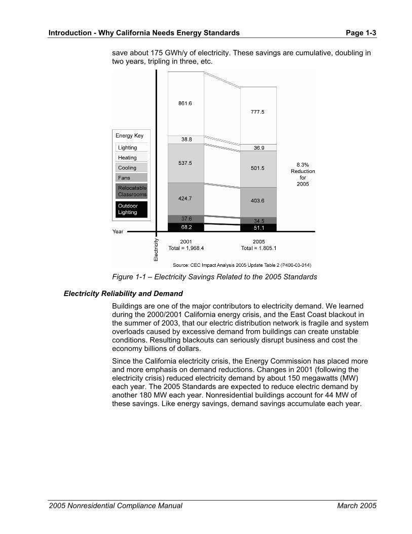
save about 175 GWh/y of electricity. These savings are cumulative, doubling in two years, tripling in three, etc.
Figure 1-1 – Electricity Savings Related to the 2005 Standards
Electricity Reliability and Demand Buildings are one of the major contributors to electricity demand. We learned during the 2000/2001 California energy crisis, and the East Coast blackout in the summer of 2003, that our electric distribution network is fragile and system overloads caused by excessive demand from buildings can create unstable conditions. Resulting blackouts can seriously disrupt business and cost the economy billions of dollars.
Since the California electricity crisis, the Energy Commission has placed more and more emphasis on demand reductions. Changes in 2001 (following the electricity crisis) reduced electricity demand by about 150 megawatts (MW) each year. The 2005 Standards are expected to reduce electric demand by another 180 MW each year. Nonresidential buildings account for 44 MW of these savings. Like energy savings, demand savings accumulate each year.

Page 1-4 - Introduction – Why California Needs Energy Standards
2005 Nonresidential Compliance Manual March 2005
Figure 1-2 – Demand Savings Related to the 2005 Standards
Comfort Comfort is an important benefit of energy efficient buildings. Energy efficient buildings include properly designed HVAC systems, which provide improved air circulation, and high performance windows and/or shading to reduce solar gains and heat loss. Poorly designed building envelopes result in buildings that are less comfortable. Oversized heating and cooling systems do not assure comfort even in older, poorly insulated and leaky buildings.
Economics For the building owner, energy efficiency helps create a more profitable operation. From a larger perspective, the less California depends on depletable resources such as natural gas, coal and oil, the stronger and more stable the economy will remain in the face of energy cost increases. A cost-effective investment in energy efficiency helps everyone. In many ways, it is far more cost effective for the people of California to invest in saving energy than it is to invest in building new power plants.
Environment In many parts of the world, the use of energy has led to oil spills, acid rain, smog, and other forms of environmental pollution that have ruined the natural beauty people seek to enjoy. California is not immune to these problems, but appliance standards, building standards, and utility programs that promote efficiency and conservation help to maintain environmental quality. Other benefits include reduced destruction of natural habitats, which in turn helps protect animals, plants, and natural systems.
Introduction - What’s New for 2005 Page 1-5
2005 Nonresidential Compliance Manual March 2005
Global Warming Experts believe that burning fossil fuel is a major contributor to global warming; carbon dioxide is being added to an atmosphere already containing 25% more than it did two centuries ago. Carbon dioxide and other greenhouse gasses create an insulating layer around the earth that leads to global climate change. Energy Commission research shows that most of the sectors of the State economy face significant risk from climate change including water resources (from reduced snow pack), agriculture, forests, and the natural habitats of a number of indigenous plants and animals.
Scientists recommend that actions be taken to reduce emissions of carbon dioxide and other greenhouse gasses. While adding scrubbers to power plants and catalytic converters to cars is a step in the right direction, those actions do not limit the carbon dioxide we emit into the atmosphere. Using energy efficiently is a far-reaching strategy that can make an important contribution to the reduction of greenhouse gasses.
The National Academy of Sciences has urged the country to follow California's lead on such efforts, saying that conservation and efficiency should be the chief element in energy and global warming policy. Their first efficiency recommendation was simple: Adopt nationwide energy efficient building codes. Energy conservation will not only increase comfort levels and save California money, but it will also play a vital role in creating and maintaining a healthy environment.
1.5 What’s New for 2005 The process to develop the 2005 Standards began with a call for ideas in November 2001, moved through a series of workshops and hearings in 2002 and 2003 and concluded at the adoption hearing on November 5, 2003. Energy Commission staff, contractors, utilities and many others participated in the process. The following paragraphs summarize the principle changes that resulted.
All Buildings • Time Dependent Valuation (TDV). Source energy was replaced with
TDV energy. TDV energy values energy savings greater during periods of likely peak demand, such as hot summer weekday afternoons, and values energy savings less during off peak periods. TDV gives more credit to measures such as daylighting and thermal energy storage that are more effective during peak periods.
• New Federal Standards. Coincident with the 2005 Standards, new standards for water heaters and air conditioners took effect. These changes affect all residential buildings, but also affect many nonresidential buildings that use water heaters and/or “residential size” air conditioners.
• New Lighting in Historic Buildings. The exception to the Standards requirements for historic buildings has changed relative to lighting requirements so that only those historic or historic replica components are exempt.

Page 1-6 - Introduction – What’s New for 2005
2005 Nonresidential Compliance Manual September 2005
Nonresidential Buildings • Cool Roofs. The nonresidential prescriptive standards require “cool
roofs” (high reflectance, high emittance roof surfaces, or exceptionally high reflectance and low emittance surfaces) in all low-slope applications. The cool roof requirements also apply to roof replacements for existing buildings.
• Acceptance Requirements. Basic “building commissioning”, at least on a component basis, is required for electrical and mechanical equipment that is prone to improper installation.
• Demand Control Ventilation. Controls that measure CO2 concentrations and vary outside air ventilation are required for spaces such as conference rooms, dining rooms, lounges, and gyms.
• T-bar Ceilings. Placing insulation directly over suspended ceilings is not permitted as a means of compliance, except for limited applications.
• Relocatable Public School Buildings. Special compliance approaches are added for relocatables so they can be moved anywhere statewide.
• Duct Efficiency. R-8 duct insulation and duct sealing with field verification is required for ducts in unconditioned spaces in new buildings. Duct sealing is also required in existing buildings when the air conditioner is replaced. Performance method may be used to substitute a high efficiency air conditioner in lieu of duct sealing.
• Indoor Lighting. The lighting power limits for indoor lighting are reduced in response to advances in lighting technology.
• Skylights for Daylighting in Buildings. The prescriptive standards require that skylights with controls to shut off the electric lights are required for the top story of large, open spaces (spaces larger than 25,000 ft² with ceilings higher than 15 ft.).
• Thermal Breaks for Metal Building Roofs. Continuous insulation or thermal blocks at the supports are required for metal building roofs.
• Efficient Space Conditioning Systems. A number of measures are required that improve the efficiency of HVAC systems, including variable speed drives for fan and pump motors greater than 10 hp, electronically-commutated motors for series fan boxes, better controls, efficient cooling towers, and water cooled chillers for large systems.
• Unconditioned Buildings. New lighting standards—lighting controls and power limits—applies to unconditioned buildings, including warehouses and parking garages. Lighting power tradeoffs are not permitted between conditioned and unconditioned spaces.
• Compliance Credits. Procedures are added for gas cooling, underfloor ventilation.
Introduction - Mandatory Measures and Compliance Approaches Page 1-7
2005 Nonresidential Compliance Manual March 2005
Outdoor Lighting • Lighting Power Limits. The Standards set limits on the power that can
be used for outdoor lighting applications such as parking lots, driveways, pedestrian areas, sales canopies, and car lots. The limits vary by lighting zones or ambient lighting levels. Lighting power tradeoffs are not permitted between outdoor lighting and indoor lighting.
• Shielding. Luminaires in hardscape areas larger than 175 W are required to be cutoff luminaires, which will save energy by reducing glare.
• Bi-level Controls. In some areas outdoor lighting controls are required, including the capability to reduce lighting levels to 50%.
Signs • Lighting Power Limits. Lighting power limits (or alternative equipment
efficiency requirements) apply to externally and internally illuminated signs used either indoors or outdoors.
1.6 Mandatory Measures and Compliance Approaches In addition to the mandatory measures (Section 1.6.1), the Standards provide two basic methods for complying with Nonresidential energy budgets: the prescriptive approach and the performance approach. The mandatory measures must be installed with either of these but note that mandatory measures may be superseded by more stringent measures under the prescriptive approach.
• The prescriptive approach (composed of prescriptive requirements described in Chapters 3, 4, 5, and 6) is the simpler. Each individual energy component of the proposed building must meet a prescribed minimum efficiency. The prescriptive approach offers relatively little design flexibility but is easy to use. There is some flexibility for building envelope components, such as walls, where portions of the wall that do not meet the prescriptive insulation requirement may still comply as long as they are area-weighted with the rest of the walls, and the average wall performance complies.
• The performance approach (Chapter 8) is more complicated but offers considerable design flexibility. The performance approach requires an approved computer software program that models a proposed building, determines it’s allowed energy budget, calculates its energy use, and determines when it complies with the budget. Design options such as window orientation, shading, thermal mass, zonal control, and building configuration are all considered in the performance approach. This approach is used because of the flexibility and because it provides a way to find the most cost-effective solution for complying with the Standards.
For additions and alterations, see Chapter 8 for details of compliance approaches that are available.

Page 1-8 - Introduction – Mandatory Measures and Compliance Approaches
2005 Nonresidential Compliance Manual March 2005
1.6.1 Mandatory Measures
With either the prescriptive or performance compliance paths, there are mandatory measures that must always be installed. Many of the mandatory measures deal with infiltration control and lighting; others require minimum insulation levels and equipment efficiency. The minimum mandatory levels are sometimes superseded by more stringent prescriptive requirements. For example, if mandatory measures specify R-19 ceiling insulation and the prescriptive approach, specifies R-38 ceiling insulation, then R-38 must be installed. Conversely, the mandatory measures may be of a higher efficiency than permitted under the performance approach; in these instances, the higher mandatory levels must be installed. For example, a building may comply with the performance computer modeling with only R-7 insulation in a raised floor; however, if mandatory requirement for this raised floor is R-19, the R-19 must be installed consistent with the mandatory requirements.
1.6.2 Prescriptive Packages
Building Envelope The prescriptive envelope requirements are determined either by the Envelope Component Approach or the Overall Envelope Approach. These two approaches are described in detail in Chapter 3, beginning with an introduction in Section 3.1. The stringency of the envelope requirements varies according to climate zone and occupancy type.
Mechanical The prescriptive mechanical requirements are described in detail in Chapter 4. The prescriptive Standards do not offer any alternative approaches, but specify hardware features and design procedures that must be followed.
Indoor Lighting The prescriptive lighting requirements are determined by one of three methods: the Complete Building Method, the Area Category Method, or the Tailored Method. These three approaches are described in detail in Chapter 5, beginning with Section 5.2.2. Prescriptive Approach. The allowed lighting under the Standards varies according to the requirements of the particular building occupancy or task requirements.
Outdoor Lighting The prescriptive lighting requirements are determined by lighting application type (general and specific) and the lighting zone for each application. These approaches are discussed in detail in Chapter 6, beginning with 6.4 Outdoor Lighting Power Allowances.
1.6.3 Performance Approach
The performance approach, also known as the computer method, requires that the annual TDV energy be calculated for the proposed house and compared to the TDV energy budget. TDV energy is the “currency” for the performance approach. TDV energy not only considers the type of energy that is used (electricity, gas, or propane), but also when it is used. Energy saved during

Introduction - Scope and Application Page 1-9
2005 Nonresidential Compliance Manual March 2005
periods when California is likely to have a statewide system peak is worth more than energy saved at times when supply exceeds demand. Appendix III of the Joint Appendices has more information on TDV energy.
The performance approach allows a wider variety of design strategies and provides greater flexibility than the prescriptive approach. It is based on an energy simulation model of the building. The Standards specify the method for determining an energy budget for the building. This energy budget represents the upper limit of energy use allowed for that particular building. The designer is permitted to trade off different aspects of the building design, one against the other, when permit applications for more than one component are submitted at the same time. As long as total energy use considering all installed components does not exceed the allowed budget, the tradeoff is acceptable.
Three basic steps are involved:
1. Design the building with energy efficiency measures that are expected to be sufficient to meet the energy budget. (The prescriptive approach requirements provide a good starting point for the development of the design.)
2. Demonstrate that the building complies with the mandatory measures (see Chapters 3, 4, 5 and 6).
3. Using an approved calculation method, model the energy consumption of the building using the proposed features to create the proposed energy budget. The model will also automatically calculate the allowed energy budget for the proposed building.
If the proposed energy budget is no greater than the allowed energy budget, the building complies.
1.7 Scope and Application The California Standards apply to both nonresidential and residential buildings. This manual addresses the requirements for nonresidential buildings, including hotels, motels, and high-rise residential buildings (those over three stories in height). The Residential Manual addresses the requirements for low-rise residential buildings.
1.7.1 Building Types Covered
The nonresidential Standards apply to all California Building Code (CBC) occupancies of Group A, B, E, F, H, M, R, S or U buildings that are mechanically heated or mechanically cooled resulting in directly or indirectly conditioned space. Nonresidential buildings that have space conditioning, but do not meet the criteria of a directly or indirectly conditioned building, must comply with the lighting requirements only.
The Standards do not apply to CBC Group I. This group includes such buildings as hospitals, daycare, nursing homes, and prisons. The Standards also do not apply to buildings that fall outside the jurisdiction of California building codes, such as mobile structures.

Page 1-10 - Introduction – Scope and Application
2005 Nonresidential Compliance Manual March 2005
Historic Buildings Exception 1 to §100(a) states that qualified historic buildings, as defined in the California Historical Building Code Title 24, Part 8 or California Building Code, Title 24, Part 2, Volume I, Chapter 34, Division II are not covered by the Building Energy Efficiency Standards. Building Energy Efficiency Standards §146 (a) 5.Q clarifies that lighting systems in qualified historic buildings are exempt from the lighting power allowances only if they consist solely of historic lighting components or replicas of historic lighting components. If lighting systems in qualified historic buildings contain some historic lighting components or replicas of historic components, combined with other lighting components, only those historic or historic replica components are exempt. All other lighting systems in qualified historic buildings must comply with the Building Energy Efficiency Standards.
The California Historical Building Code (CHBC) §102.1.1 specifies that all non-historical additions must comply with the regular code for new construction, including the Building Energy Efficiency Standards. CHBC §901.5 specifies that when new or replacement mechanical, plumbing, and electrical (including lighting) equipment or appliances are added to historic buildings they should comply with the Building Energy Efficiency Standards, including the Appliance Efficiency Regulations.
The California State Historical Building Safety Board has final authority in interpreting the requirements of the CHBC and determining to what extent the requirements of the Building Energy Efficiency Standards apply to new and replacement equipment and other alterations to qualified historic buildings. It should be noted that in enacting the State Historical Building Code legislation, one of the intents of the Legislature was to encourage energy conservation in alterations to historic buildings (Health and Safety Code §18951).
Additional information about the CHBC can be found on the following website:
http://www.dsa.dgs.ca.gov/StateHistoricalBuildingSafetyBoard/
Contact the State Historical Building Safety Board at (916) 445-7627.
Low-rise Residential Buildings The low-rise residential Standards cover single-family and low-rise residential buildings (occupancy groups R1, R2, and R3) and CBC Group U buildings including:
• All single-family dwellings of any number of stories.
• All duplex (two-dwelling) buildings of any number of stories.
• All multi-family buildings with three or fewer habitable stories (Groups R-1 and R-2).
• Additions and alterations to all the above buildings.
• Private garages, carports, sheds and agricultural buildings.
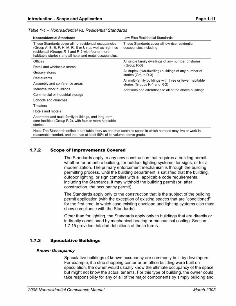
Introduction - Scope and Application Page 1-11
2005 Nonresidential Compliance Manual March 2005
Table 1-1 – Nonresidential vs. Residential Standards
Nonresidential Standards Low-Rise Residential Standards
These Standards cover all nonresidential occupancies (Group A, B, E, F, H, M, R, S or U), as well as high-rise residential (Groups R-1 and R-2 with four or more habitable stories), and all hotel and motel occupancies.
These Standards cover all low-rise residential occupancies including:
Offices Retail and wholesale stores Grocery stores Restaurants Assembly and conference areas Industrial work buildings Commercial or industrial storage Schools and churches Theaters Hotels and motels Apartment and multi-family buildings, and long-term care facilities (Group R-2), with four or more habitable stories
All single family dwellings of any number of stories (Group R-3) All duplex (two-dwelling) buildings of any number of stories (Group R-3) All multi-family buildings with three or fewer habitable stories (Groups R-1 and R-2) Additions and alterations to all of the above buildings
Note: The Standards define a habitable story as one that contains space in which humans may live or work in reasonable comfort, and that has at least 50% of its volume above grade.
1.7.2 Scope of Improvements Covered
The Standards apply to any new construction that requires a building permit, whether for an entire building, for outdoor lighting systems, for signs, or for a modernization. The primary enforcement mechanism is through the building permitting process. Until the building department is satisfied that the building, outdoor lighting, or sign complies with all applicable code requirements, including the Standards, it may withhold the building permit (or, after construction, the occupancy permit).
The Standards apply only to the construction that is the subject of the building permit application (with the exception of existing spaces that are "conditioned" for the first time, in which case existing envelope and lighting systems also must show compliance with the Standards).
Other than for lighting, the Standards apply only to buildings that are directly or indirectly conditioned by mechanical heating or mechanical cooling. Section 1.7.15 provides detailed definitions of these terms.
1.7.3 Speculative Buildings
Known Occupancy Speculative buildings of known occupancy are commonly built by developers. For example, if a strip shopping center or an office building were built on speculation, the owner would usually know the ultimate occupancy of the space but might not know the actual tenants. For this type of building, the owner could take responsibility for any or all of the major components by simply building and
Page 1-12 - Introduction – Scope and Application
2005 Nonresidential Compliance Manual March 2005
showing energy compliance for the envelope, and leaving the lighting and HVAC improvements to the tenants (or the project could include the other systems as well). In most instances upgrading the envelope later increases total construction costs, as it is easier to install envelope features at time of construction of the shell than afterwards.
The obvious example is declaring the shell to be unconditioned, not insulating the shell and having to insulate the shell as part of the tenant improvement that adds air-conditioning. This increases the final cost of the building and should render the shell less valuable for spaces that are ultimately going to be conditioned.
A less obvious example that is new to the 2005 standards, is the shell of a building that will ultimately become a big box retail store or a warehouse with lighting power densities > 0.5 W/ft2, ceiling heights > 15 ft, and an enclosed area > 25,000 ft2. Such occupancies are prescriptively required to have skylights and daylighting controls. Installing skylights in the roof of the speculative building shell is less expensive than retrofitting them later. This should be considered when designing speculative shell buildings for the big box retail or warehouse market, as they will be more saleable than those requiring skylight retrofits.
Because compliance may be demonstrated for each component separately, the owner can simply demonstrate that the systems being built meet the Standards. The remaining construction and Standards compliance work can be dealt with as each tenant obtains building permits for work in their individual spaces (see Section 1.7.10).
Often, the developer will seek to minimize first cost by delaying compliance and construction of as much of the project as possible. While this can be done under the Standards, there are two disadvantages:
1. If all Standards compliance is deferred by declaring the building to be unconditioned, the owner needs to understand the potential problems that could arise later when the building is conditioned.
2. If only the envelope or lighting systems are shown to comply, the owner loses the opportunity to apply the performance approach to the entire building and so to make trade-offs between systems to optimize the cost-effectiveness of the design.
Unknown Occupancy Speculative buildings are often built for which the ultimate occupancy is determined at the time of leasing and not during construction of the building shell. The structure, for example, could eventually be used as an office, a warehouse, a restaurant, or retail space. Because the Standards treat these occupancies in a similar fashion, the fact that the ultimate occupancy is unknown is not a significant problem. The major items affected by the ultimate occupancy have to do with lighting and ventilation requirements. If at the time of permitting a tenant is not identified for a multi-tenant space, the tenant leased space lighting power allowances from Standards Table 146-C shall be used.
The major problem that can occur with this type of building comes when the owner elects to declare it as an unconditioned building and defer Standards compliance until such time as a tenant installs mechanical space conditioning equipment.
Introduction - Scope and Application Page 1-13
2005 Nonresidential Compliance Manual March 2005
1.7.4 Mixed Use Buildings
Because the Standards are different for residential and nonresidential buildings, and because mixed-use buildings occasionally include more than one type of occupancy, there is potential for confusion in application. The Standards address these circumstances regarding mixed-use buildings:
• Minor Occupancy (exception to §100(f)). If the minor occupancy or occupancies occupy less than 10% of the total conditioned floor area, then they may optionally be treated as if they were of the major occupancy. The mandatory measures applicable to the minor occupancy, if different from the major occupancy, would still apply.
• Different Nonresidential Occupancies. When both of these occupancies fall under the Nonresidential Standards, they would be dealt with together under the same compliance process. Although the occupancies may have different envelope and lighting requirements, these are not so different as to require special compliance procedures.
• Hotel/Motel and Nonresidential Occupancies. A hotel/motel with guest rooms, restaurants, sports facilities and other nonresidential occupancies is defined as a hotel/motel occupancy. The only variance is that the guestroom envelope and lighting and HVAC control requirements are different.
• Mixed Residential and Nonresidential Occupancies. These occupancies fall under different sets of Standards, they are considered separately. Two compliance submittals must be prepared, each using the calculations and forms of its respective Standards.
Example 1-1
Question
A 250,000ft² high-rise office building includes a small 500ft² apartment for use by visiting executives. This is clearly a residential occupancy, so is the apartment required to meet the residential requirements of the Standards?
Answer
No. It occupies less than 10% of the total conditioned floor area, so it is a minor occupancy and may be treated as part of the office occupancy. Residential mandatory measures apply.
1.7.5 High-rise Residential
High-rise residential buildings (four habitable stories or more) are covered by this manual and the Nonresidential Standards.
The Standards apply separately to the living quarters and to other areas within the building. Living quarters are those non-public portions of the building in which a resident lives. High-rise residential dwelling units must incorporate the envelope and mechanical elements of the Nonresidential Standards, with the lighting and service hot water needs of residential buildings. Outdoor lighting, including for parking lots and garages for eight or more vehicles, and for indoor

Page 1-14 - Introduction – Scope and Application
2005 Nonresidential Compliance Manual March 2005
or outdoor signs (other than exit signs) must comply with the Nonresidential Standards. Exit signs must comply with the Appliance Standards.
The following subsections discuss the special compliance requirements that apply to high-rise residential occupancies.
Mandatory Measures The mandatory measures for envelope, mechanical and indoor lighting, outdoor lighting and signs apply to high-rise residential buildings. Special requirements for high-rise residential buildings are summarized below:
• Living quarters must meet the applicable indoor lighting requirements for low-rise residential buildings.
• Outdoor lighting must meet the applicable outdoor lighting requirements of the Nonresidential Standards.
• Indoor and outdoor signs (other than exit signs) must comply with the Nonresidential Standards. Exit signs must comply with the Appliance Standards.
• High-rise residential occupancies must meet setback requirements applicable to low-rise residential occupancies.
• Readily accessible area switching controls are not required in public areas provided switches that control the lights in public areas are accessible to authorized personnel.
• Automatic shut-off controls are not required for living quarters.
Prescriptive Compliance The prescriptive requirements for envelope, mechanical and lighting apply to high-rise residences. The following summarize the special prescriptive requirements for high-rise residential buildings.
• The envelope must meet the prescriptive envelope criteria for high-rise residential buildings (Standards Table 143-B).
• High-rise residential living quarters are not required to have economizer controls.
• High-rise residential living quarters are exempt from the lighting power density requirements. However, kitchens must meet the residential 50% high efficacy wattage requirements of the Nonresidential Standards. In addition, bathrooms must meet the efficiency and control requirements of §150(k). While there are no Prescriptive lighting requirements for residential buildings, lighting within the dwelling units must meet the lighting requirements of §150(k).
• Each occupancy (other than living quarters) in the high-rise residence must comply with the nonresidential lighting requirements.
Performance Compliance The rules for high-rise residential performance compliance are identical to the performance compliance rules for all nonresidential buildings. The area of each
Introduction - Scope and Application Page 1-15
2005 Nonresidential Compliance Manual March 2005
function of a high-rise residence is input into the program along with its corresponding envelope, mechanical and lighting features. The computer program will automatically calculate an energy budget for the standard design, and the proposed design's energy use.
1.7.6 Hotels and Motels
This section discusses both the similarities and differences between the requirements for a hotel/motel and other nonresidential or high-rise residential buildings.
The design of a hotel or motel is unique in that the design must incorporate a wide variety of occupancies and functions into one structure. The occupancies range from nonresidential occupancies to hotel/motel guest rooms. Design functions that affect guests range from the "experience of arrival" created through the main lobby's architectural features to the thermal comfort of the guest rooms. Other functions that hotel/motel designs must address include restaurants, kitchens, laundry, storage, light assembly, outdoor lighting, sign lighting, and other items that are necessary to the hotel/motel function. In short, these structures can range from simple guest rooms with a small office, to a structure encompassing a small city.
Like other occupancies: compliance is submitted for the features covered in the permit application only. The nonresidential areas must meet the envelope, mechanical, indoor lighting outdoor lighting, and sign lighting portions of the Nonresidential Standards, and the guest room portions of hotels/motels must meet the envelope, mechanical and lighting provisions applicable only to hotels/motel guest rooms. In essence, each portion of the building individually complies with the provisions applicable to that occupancy.
Since hotel/motels are treated as a mixture of occupancies covered by the Standards, the concepts presented at the beginning of each chapter apply to hotels/motels as they would any other nonresidential occupancy.
Mandatory Measures The mandatory measures for envelope, mechanical, indoor lighting, outdoor lighting, and sign lighting apply to hotels/motels. The following bullets describe special requirements or exceptions for hotel/motel buildings.
• Ninety percent (90%) of the hotel/motel guest rooms must meet the applicable lighting requirements for low-rise residential buildings.
• Outdoor lighting must meet the applicable outdoor lighting requirements.
• Indoor and outdoor signs (other than exit signs) must comply with the Nonresidential Standards. Exit signs must comply with the Appliance Standards.
• Hotel and motel guest room thermostats shall have numeric temperature settings.
• Readily accessible area switching controls are not required in public areas provided switches that control the lights in public areas are accessible to authorized personnel.
Page 1-16 - Introduction – Scope and Application
2005 Nonresidential Compliance Manual March 2005
• Automatic shut-off controls are not required for hotel/motel guest rooms.
Prescriptive Compliance The prescriptive requirements for envelope, mechanical and lighting apply to hotel/motels. The following prescriptive requirements are specific to hotel/motels:
• Hotel/motel guest rooms must meet the prescriptive envelope criteria for high-rise residential buildings rather than the prescriptive criteria for nonresidential buildings.
• Hotel and motel guest rooms are not required to have economizer controls.
• Guest rooms in hotel/motels are exempt from the lighting power density requirements. However, lighting must meet the low-rise residential requirements of §150 (k).
• Each occupancy (other than guest rooms) in the hotel/motel must comply with the nonresidential lighting requirements.
Performance Compliance The rules for performance compliance are identical to the rules for complying for all other nonresidential and high-rise residential buildings. The area of each function of a hotel/motel is input into the program along with its corresponding envelope, mechanical and indoor lighting features. The computer program will automatically calculate an energy budget for the standard design, and the proposed design’s energy use.
1.7.7 Live-Work Spaces
Live-work buildings are a special case of mixed occupancy buildings, as they combine residential and nonresidential uses within individual units. The building envelope of live-work buildings are required to meet the requirements of either the low-rise or high-rise residential standards, depending on the number of habitable floors. Low-rise Residential Standards apply to live/work units that are part of a building with no more than three habitable stories. Note that the loft space in a unit with high ceilings is not generally counted as a separate story (see definitions later in this chapter). The residential requirement applies since these buildings operate (and therefore are conditioned) 24 hours per day. Lighting in designated workspaces is required to show compliance with the nonresidential lighting requirements (§146).
1.7.8 Unconditioned Space
Unconditioned space is neither directly nor indirectly conditioned, as defined in the previous section. Both the requirements for lighting and minimum skylight area apply to unconditioned space. Some typical examples of spaces that may be unconditioned:
• Enclosed parking structures.

Introduction - Scope and Application Page 1-17
2005 Nonresidential Compliance Manual March 2005
• Automotive workshops.
• Covered entry courts or walkways.
• Enclosed outdoor dining areas.
• Greenhouses.
• Loading docks.
• Mechanical/electrical equipment rooms.
Keep in mind that these kinds of spaces are not always unconditioned. The specifics of each case must be determined. See Figure 1-3 to determine whether a space is unconditioned or conditioned.
Figure 1-3 – Type of Conditioned Space and Scope of Compliance

Page 1-18 - Introduction – Scope and Application
2005 Nonresidential Compliance Manual March 2005
1.7.9 Newly Conditioned Space
When previously unconditioned space becomes conditioned, the space is then considered an “addition” and all the building’s components must then comply as if it were a new building.
This situation has potentially significant construction and cost implications. For example, if an unconditioned warehouse is upgraded with a heating system thus becoming conditioned space, the building envelope must comply with the current envelope requirements and the lighting system must be brought into conformance with the current lighting requirements, including mandatory wiring and switching. If the envelope has large windows, it is conceivable that some would have to be eliminated or replaced with more efficient windows. If the lighting system is inefficient, fixtures might have to be removed and new, more efficient fixtures installed.
This requirement can cause difficulty when an owner of a building seeks exemption from complying with the Standards by erecting a shell with no plans to condition it. For example, the owner of an office building obtains a permit for the structure and envelope, but wishes to leave the space conditioning and lighting improvements to the tenants. If that owner claims unconditioned status for that building, the owner does not have to demonstrate compliance with the envelope requirements of the Standards, but does have to demonstrate compliance with the lighting requirements. If at the time of permitting a tenant is not identified for a multi-tenant space, the tenant leased space lighting power allowances from Standards Table 146-C shall be used. As soon as the tenant applies for a permit to install the HVAC equipment, however, the envelope and any existing lighting in the shell must then be brought into full compliance with the requirements for the occupancy designated at the time of the HVAC permit application. (This is the only circumstance when systems, other than those subject to the current permit application, fall under the Standards.) If the building was initially designed in a way that makes this envelope compliance difficult, the building envelope may require expensive alterations to bring it into compliance.
Many building departments require the owner to sign an affidavit at the time of the initial building permit for the shell, acknowledging the potential difficulties of future envelope or lighting compliance.
To minimize Standards compliance difficulties, the recommended practice is to demonstrate energy compliance at the time the envelope is built, and to demonstrate compliance for the lighting systems when lighting systems are installed.
1.7.10 New Construction in Existing Buildings
Alterations, tenant improvements, and repairs are new construction in an existing building. For example, the base building has been constructed, but the individual tenant spaces have not been completed. Tenant improvements can include work on the envelope, the mechanical or the lighting systems. Whatever the case, the system or systems being installed are considered to be new construction, and must comply with some or all of the current Standards, depending on the extent of the changes (see following sections).

Introduction - Scope and Application Page 1-19
2005 Nonresidential Compliance Manual March 2005
The only circumstance when systems other than those subject to the current permit application come under scrutiny is when the tenant improvement results in the conditioning of previously unconditioned space.
1.7.11 Alterations to Occupied Spaces §149(b)
An alteration is any change to a building’s water heating system, space conditioning system, indoor lighting system, outdoor lighting system, sign, or envelope that is not an addition. Alterations or renovations to existing conditioned spaces have their own set of rules for energy compliance. They are covered in a separate section of the Standards, §149(b). (Additions are discussed in §149(a).)
In summary, the alteration rules are:
1. The Standards apply only to those portions of the systems being altered; untouched portions need not comply with the Standards.
2. If an envelope, indoor lighting, outdoor lighting or sign lighting alteration increases the energy use of the altered systems, the alteration must comply with the current Standards.
3. Alterations must comply with the mandatory measures for the changed components.
4. New systems in the alteration must comply with the current Standards.
5. In an existing unconditioned building, outdoor lighting, or sign lighting system, altered lighting must meet mandatory measures for the changed lighting component. Alterations that increase the connected lighting load or replace more than 50% of the lighting fixtures must meet current Standards. Replacement of parts of an existing lighting fixture, including installing new ballasts or lamps, without replacing the entire luminaires is not an alteration subject to the alteration requirements.
6. In an existing, unconditioned building where evaporative cooling is added the existing unaltered envelope and lighting do not need to be brought into compliance with current Standards.
The effect of these rules is that, in most cases the existing systems (envelope and lighting) set the standard for the altered systems. For example, if the existing lighting system is changed but does not increase the connected lighting load, or replace more than 50% of lighting fixtures in enclosed spaces where lighting alterations are proposed, must meet current standards. The same holds true for changes to the envelope: if the overall heat loss or heat gain is not increased and it meets its applicable mandatory measures, then it complies. Mechanical system alterations are governed primarily by the mandatory measures.
The alternative alteration rule is to make changes to the existing building so that the entire building (existing and alteration) complies with the performance approach of the current Standards. Keep in mind that, under the performance approach, credit is given only for systems that are actually changed in the current construction process.

Page 1-20 - Introduction – Scope and Application
2005 Nonresidential Compliance Manual March 2005
Example 1-2
Question
An owner wants to add less than 50 ft2 of new glazing in an old building. This will increase the glazing area. How do the Standards apply?
Answer
The added glass must meet the U-value requirements but not the shading requirements in §143. In addition, the window must be rated for U-factor and SHGC either with default values and labels or be rated and labeled in accordance with NFRC standards and programs.
Example 1-3
Question
A building owner wants to change existing lighting fixtures with new ones. Do the Standards restrict the change in any way?
Answer
If more than 50% of the fixtures are replaced, in the permitted space (excluding enclosed spaces where no new lighting fixtures are proposed), or the connected load is increased, the Standards will treat this as a new lighting system that must comply with §146. Any applicable mandatory requirement affected by the alteration applies, and the mandatory switching requirements would apply to the improved system if the circuiting were altered. Title 20 Appliance Efficiency Regulations requirements for ballasts would also apply.
Example 1-4
Question
A building owner wants to rearrange some interior partitions and re-position the light fixtures in the affected rooms. Do the Standards apply to the work?
Answer
Each of the newly arranged rooms must have its own light switches. Since there is no change in the connected lighting load or the exterior envelope, only the mandatory light switching requirements would apply.
Example 1-5
Question
A building owner wants to re-arrange some duct work and add some additional fan coils to an existing HVAC system to improve comfort. Do the Standards apply to the work?
Answer
There would be no change in the load on the system nor any increase in its overall capacity, so the Standards would not apply to the central system. Only the duct construction requirements apply to altered ducting.
Example 1-6
Question
A building owner wants to replace an existing chiller. No other changes will be made to the HVAC system. Do the Standards restrict the change in any way?

Introduction - Scope and Application Page 1-21
2005 Nonresidential Compliance Manual March 2005
Answer
The mandatory efficiency requirements would govern the efficiency of the new chiller. The other parts of the system are unchanged and therefore unaffected by the Standards.
Example 1-7
Question
A building owner has a high ceiling space and wants to build a new mezzanine space within it. There will be no changes to the building envelope or to the central HVAC system. There will be new lighting installed. How do the Standards apply?
Answer
Since a mezzanine does not add volume, it is an alteration, not an addition. The existing systems are not affected unless they are altered. The new lighting must comply with all requirements of the Standards. The envelope is unchanged, so there are no requirements for it. The mechanical system duct work is simply extended without increase in system capacity, so only the duct construction and insulation requirements apply.
1.7.12 Additions §149(a)
An addition is any change to a building that increases conditioned floor area and conditioned volume. Additions involve either the construction of new, conditioned space and conditioned volume, or the installation of space conditioning in a previously unconditioned space. The mandatory measures, and either the prescriptive or the performance requirements apply. The heating, lighting, envelope, and water heating systems of additions are treated the same as for new buildings. The only exception to this is if the existing systems are simply extended into the addition: Standards Exception to §149(a). Refer above to Section 1.7.8 for further discussion of previously unconditioned space.
There are three options for the energy compliance of additions under the Standards:
Option 1 – Addition Alone Treat the addition as a stand-alone building with adiabatic walls to conditioned space (§149(a)1 and (§149(a)2.B.1). This option can employ either the prescriptive or the performance approach. Adiabatic means the common walls are assumed to have no heat transfer between the addition and the adjacent conditioned space, and are ignored entirely.
Option 2 – Existing-Plus-Addition Combine the existing building with the addition (§149(a)2.B.2). This option only works with the performance approach. It uses the custom budget approach to develop an energy budget for the existing building and a standard version of the addition. These combine into a total building energy budget. The combined building is then modeled as proposed. If it meets the budget, the addition complies. The Standard Design for any alterations to existing lighting and mechanical systems must meet the requirements for altered systems in §149(b).
Page 1-22 - Introduction – Scope and Application
2005 Nonresidential Compliance Manual March 2005
This option will generally work to ease the energy requirements of the addition only if there are energy improvements to the existing building. It does allow the designer to make a relatively energy inefficient addition comply.
Option 3 – Whole Building The existing structure combined with the addition can be shown to comply as a whole building with all requirements of the current Standards for envelope, lighting and mechanical.
Example 1-8
Question
A restaurant adds a greenhouse-style dining area with large areas of glazing. It is directly conditioned space. How can it comply with the Standards?
Answer
Because of its large glass area, it will not comply on its own. By making substantial energy improvements to the existing building (lighting, mechanical or other envelope features), or upgrading the existing building so that the entire building meets the requirements for new construction, it is possible for the combined building to comply. The performance approach would be used to model the combined existing/new building.
1.7.13 Changes of Occupancy
A change of occupancy alone does not require any action under the Energy Standards. If changes are made to the building, however, then the rules for alterations or additions apply (see Sections 1.7.11 and 1.7.12).
If the change in occupancy involves converting from a residential to a nonresidential occupancy or vice versa (changes defined by the California Building Code occupancy definitions), then the Standards applicable to the new occupancy would govern any alterations made to the building. For example, if a home is converted to law offices, and a new lighting system is installed, the nonresidential lighting requirements would apply. If a new HVAC system is installed, all the nonresidential HVAC requirements would have to be met.
If no changes are proposed for the building, it is advisable to consider the ventilation requirements of the new occupancy. For example, if a residence is converted to a hair salon, the ventilation rates of the building should be considered. With new sources of indoor pollution, the existing residential ventilation rates would likely not be adequate for the new uses. However, no change is required by the Standards.
1.7.14 Repairs
A repair is the reconstruction or renewal of any part of an existing building for the purpose of its maintenance. Repairs shall not increase the preexisting energy consumption of the required component, system, or equipment.
Introduction - Scope and Application Page 1-23
2005 Nonresidential Compliance Manual March 2005
1.7.15 Scope Concepts and Definitions
This section explains the definitions and terms necessary for understanding the scope and application of the Nonresidential Standards. In most cases, a careful reading of these definitions will resolve questions of interpretation. See also the Glossary in Joint Appendix I.
Building is any structure or space for which a permit is sought. By this definition, a building is not necessarily a complete physical structure. For the Standards, a building in this sense can be a lighting system recircuiting project, because this would require an electrical permit. Conditioned Floor Area (CFA) is the floor area (in square ft) of enclosed conditioned space on all floors of a building, as measured at the floor level of the exterior surfaces of exterior walls enclosing the conditioned space. Once the spaces that are directly or indirectly conditioned are identified, then it is possible to calculate the conditioned floor area of the building. This number is used for various calculation purposes in complying with the Standards. The CFA is generally calculated from dimensions on the floor plans of the building. It is measured from the outside surfaces of exterior walls, with the dimensions taken at floor level. This definition helps mitigate any complexity from sloping walls, bay windows and other unique building details.
Conditioned Space is space in a building that is either directly conditioned or indirectly conditioned. In most circumstances it is obvious whether a space is conditioned or unconditioned. There are, however, special circumstances that require a closer look at the definitions of directly and indirectly conditioned space. Directly Conditioned Space is an enclosed space that is provided with wood heating, is provided with mechanical heating that has a capacity exceeding 10 Btu/(hr-ft²), or is provided with mechanical cooling that has a capacity exceeding 5 Btu/(hr-ft²), unless the space conditioning system is designed and thermostatically controlled to maintain a process environment temperature less than 55°F or to maintain a process environment temperature greater than 90°F for the whole space that the system serves, or unless the space conditioning is designed and controlled to be incapable of operating at temperatures above 55°F or incapable of operating at temperatures below 90°F at design conditions. This definition contains several key ideas central to the Standards. First, mechanically heated or mechanically cooled space (discussed below) may be conditioned (i.e., it does not have to be both heated and cooled). Second, it depends on how much heating or cooling is provided to determine if the space is directly conditioned. It is not uncommon for an otherwise unheated space (such as a warehouse) to have a small area with a unit heater, such as a desk on the loading dock. This usually does not make the entire structure a heated space. The total quantity of heating provided to the space has to exceed 10 Btu/(hr-ft²). Similar logic applies to a mechanical cooling system; if it provides more than 5 Btu/(hr-ft²), it means the space is directly conditioned. Third, it matters at what temperature the space is controlled. Many spaces, such as refrigerated warehouses, are conditioned but are deliberately kept at very hot or cold temperatures. The space conditioning is not for human comfort but to serve the needs of some process, such as preventing vegetables from spoiling. If the space conditioning system is specifically designed and operated to maintain a temperature that is not within the range of 55°F through 90°F and is

Page 1-24 - Introduction – Scope and Application
2005 Nonresidential Compliance Manual March 2005
thermostatically controlled not to operate within this temperature range, then the space is not directly conditioned. Note that these spaces are treated like unconditioned spaces and therefore must meet the lighting requirements.
Enclosed Space is space that is substantially surrounded by solid surfaces. Spaces that are not enclosed are spaces that are open to the outdoors, such as covered walkways, parking structures that are open or have fenced mechanical enclosures.
Entire Building is the ensemble of all enclosed space in a building, including the space for which a permit is sought, plus all existing conditioned and unconditioned space within the structure. This definition affects lighting compliance within the complete building method.
Habitable Story is a story that contains space in which humans may work or live in reasonable comfort, and that has at least 50% of its volume above grade. This definition is important in distinguishing between high-rise and low-rise residential buildings, which are covered by different Standards and are described in separate Manuals. Basement floors with more than 50% of their volume below grade are not counted as habitable stories regardless of their actual use. In buildings on sloping ground, the calculation of volume below grade can become cumbersome, but for most buildings it will be obvious whether the floor is at least 50% above grade.
Indirectly Conditioned Space is enclosed space including, but not limited to, unconditioned volume in atria, that (1) is not directly conditioned space; and (2) either (a) has an area-weighted heat transfer coefficient to directly conditioned space exceeding that to the outdoors or to unconditioned space, or, (b) is a space through which air from directly conditioned spaces is transferred at a rate exceeding three air changes per hour. This definition is important because the Standards treat indirectly conditioned space the same as conditioned space; in other words, indirectly conditioned spaces must meet the requirements of the Standards. As a guide, professional judgment should be exercised when determining whether a space is indirectly conditioned, especially as relates to door placement in the space. When an enclosed space that is not directly conditioned has openings only into a conditioned space, it should be considered indirectly conditioned. Likewise, when an enclosed space that is not directly conditioned has openings only to the outdoors, it should be considered to be unconditioned. When enclosed spaces that are not directly conditioned have openings both to the outdoors and to conditioned spaces, an evaluation of relative heat transfer and air change rate (UA) should be used to determine the status of the space. A typical example of an indirectly conditioned space might be the stairwell of a high-rise office building. The first part of the definition is that it not be directly conditioned. This is not uncommon in stairwells. The second part of the definition is that it be provided with space conditioning energy from a space that is directly conditioned. This can be done one of two ways. The first is by conduction heat transfer. If heat is transferred in from directly conditioned space (e.g., through the walls of the stairwell) faster than it is transferred out to the unconditioned surroundings, then the space is considered to be indirectly conditioned. The second way is for the space to be ventilated with air from directly conditioned spaces. For example, if exhaust hoods draw air through a kitchen from the dining room at a rate exceeding three air changes per hour, then the kitchen will be considered indirectly conditioned space.

Introduction - Scope and Application Page 1-25
2005 Nonresidential Compliance Manual March 2005
Mechanical Cooling is lowering the temperature within a space using refrigerant compressors or absorbers, desiccant dehumidifiers, or other systems that require energy from depletable sources to directly condition the space. In nonresidential, high-rise residential, and hotel/motel buildings, cooling of a space by direct or indirect evaporation of water alone is not considered mechanical cooling (see also “directly conditioned space”). For buildings covered by this manual, evaporative cooling is not considered mechanical cooling. This means, for example, that a warehouse with only evaporative coolers does not meet the definition of mechanical cooling. Nonresidential buildings with evaporate cooling are unconditioned spaces.
Mechanical Heating is raising the temperature within a space using electric resistance heaters, fossil fuel burners, heat pumps, or other systems that require energy from depletable sources to directly condition the space. If the only source of the heat is a nondepletable source, then the system is not considered mechanical heating. Nondepletable sources would include solar collectors, geothermal sources, and heat recovered from a process, such as refrigeration chillers. Space Conditioning System is a system that provides either collectively or individually heating, ventilating, or cooling within or associated with conditioned spaces in a building. The Standards apply to conditioned space, and they govern the space conditioning systems that provide the conditioning for those spaces. Unconditioned Space is enclosed space within a building that is not directly conditioned or indirectly conditioned space. Unconditioned spaces are required to meet the Indoor Lighting Standards.
High-Rise Residential is a building, other than a hotel/motel, of occupancy group R-1 with four or more habitable stories. California Building Code Occupancy Group R-1 includes apartment houses, convents and monasteries (accommodating more than 10 persons). (See definition of Unconditioned Space above). If a building has four or more habitable stories, any residential occupancy in the building is considered high-rise residential, regardless of the number of stories that are residential.
Hotel/Motel is a building or buildings incorporating six or more guest rooms or a lobby serving six or more guest rooms, where the guest rooms are intended or designed to be used, or which are used, rented, or hired out to be occupied, or which are occupied for sleeping purposes by guests, and all conditioned spaces within the same building envelope. Hotel/motel also includes all conditioned spaces that are (1) on the same property as the hotel/motel, (2) served by the same central HVAC system as the hotel/motel, and (3) integrally related to the functioning of the hotel/motel as such, including, but not limited to, exhibition facilities, meeting and conference facilities, food service facilities, lobbies and laundries. A key part of this definition is that the hotel/motel includes all spaces within the same building envelope as the lobby or the guest rooms. This is because hotel/motel buildings are generally multi-purpose facilities. They may include such diverse spaces as restaurants, auditoriums, retail stores, offices, kitchens, laundries and swimming pools. All are treated as hotel/motel spaces.
This concept extends to other buildings associated with the hotel/motel that pass the three tests:
• Same property.

Page 1-26 - Introduction – Scope and Application
2005 Nonresidential Compliance Manual March 2005
• Same central HVAC system.
• Integrally related to the hotel/motel.
Mixed Occupancies. The Standards apply to mixed occupancies in the same way they apply to single occupancy buildings. The Low-Rise Residential Standards apply to applicable occupancies; the Nonresidential Standards apply to appropriate occupancies. If these two types occur in the same building, the building must be treated as two separate buildings for purposes of energy compliance, with each part meeting its applicable requirements. An exception provides that if one occupancy makes up 90% of the building, the entire building may comply with the provisions of the dominant occupancy. The mandatory measures for the actual occupancy will apply.
Other Occupancy Definitions. There are over 35 additional occupancy definitions in the Standards. They are used primarily to assign lighting area categories. Refer to the Glossary in Joint Appendix I for these definitions (found alphabetically under “Occupancy Type)”.
Example 1-9
Question
If a space were 1,000 ft², how large would the heating system have to be to make the space directly conditioned?
Answer
The heating system would have to be larger than 10 Btu/(hr-ft²) x 1,000 ft² = 10,000 Btu/hr output to meet the definition of directly conditioned space.
Example 1-10
Question
A water treatment plant has a heating system installed to prevent pipes from freezing. The heating system exceeds 10 Btu/(hr-ft²) and operates to keep the space temperature from falling below 50°F. Is this plant directly conditioned?
Answer
Not if the heating system is sized to meet the building load at 50°F and is thermostatically controlled to prevent operating temperatures above 50°F. The definition of directly conditioned space excludes spaces that have space conditioning designed and controlled to be incapable of operating at temperatures above 55°F at design conditions. Under these conditions, the space is not directly conditioned.
Example 1-11
Question
A manufacturing facility will have space cooling to keep the temperature from exceeding 90°F. If the thermostat will not allow cooling below 90°F is this facility directly conditioned?
Answer
No, this facility is not directly conditioned. The definition of directly conditioned space excludes spaces where the space conditioning system is designed and controlled to be incapable of operating at temperatures below 90°F at design conditions.

Introduction - Scope and Application Page 1-27
2005 Nonresidential Compliance Manual March 2005
Example 1-12
Question
The accompanying sketch shows a building with three unconditioned spaces (none has a direct source of mechanical heating or cooling). The air transfer rate from the adjacent conditioned spaces is less than three air changes per hour. The area weighted heat transfer coefficients of the walls (UA) are shown on the sketch. The roof/ceiling area weighted heat transfer coefficients (UA) for each of the three unconditioned spaces is 90 Btu/Hr -°F.
Are any of these spaces indirectly conditioned?
C
AB
UA=75
UA=75
UA=75
UA=75 UA=75
UA=75
UA=70
UA=70
UA=70
UA=70
UA=70
UA=70
Answer
Because the air change rate is low, we evaluate each space on the basis of heat transfer coefficients through the walls and roof. It is further assumed that the floors are adiabatic. Therefore, the heat transfer will be proportional to the area weighted heat transfer coefficients of the walls and roof/ceilings.
SPACE A: The area weighted heat transfer coefficient to directly conditioned space is 3 x (75 Btu/Hr-°F) = 225 Btu/Hr-°F. The area weighted heat transfer coefficient to the outdoors or to unconditioned space is 70 Btu/Hr-°F + 90 Btu/Hr-°F = 160 Btu/Hr-°F. Since the heat transfer coefficient from Space A to the conditioned space is greater than heat transfer coefficient from Space A to outside, Space A is considered indirectly conditioned.
SPACE B: The area weighted heat transfer coefficient to directly conditioned space is 75 Btu/Hr-°F. The area weighted heat transfer coefficient to the outdoors or to unconditioned space is (3 x 70 Btu/Hr-°F) + 90 Btu/Hr-°F = 300 Btu/Hr-°F. Since the heat transfer coefficient from Space B to the conditioned space is less than the heat transfer coefficient from Space B to outside, Space B is considered unconditioned.
SPACE C: The area weighted heat transfer coefficient to directly conditioned space is (2 x 75 Btu/Hr-°F = 150 Btu/Hr-°F. The area weighted heat transfer coefficient to the outdoors or to unconditioned space is (2 x 70 Btu/Hr-°F) + 90 Btu/Hr-°F = 230 Btu/Hr-°F. Since the heat transfer coefficient from Space C to the conditioned space is less than the heat transfer coefficient from Space C to outside, Space C is considered unconditioned.
Example 1-13
Question
A four-story building has one floor retail, two floors are offices and the fourth floor is residential (as defined in the UBC). Is the residential space high-rise or low-rise?
Answer
It is a high-rise residential space. Even though there is only one floor of residential occupancy, the building has four habitable stories, making it a high-rise building.

Page 1-28 - Introduction – About the Standards
2005 Nonresidential Compliance Manual March 2005
1.8 About the Standards History Section 25402 of the Public Resources Code
The Legislature adopted the Warren-Alquist Act which created the California Energy Commission (Energy Commission) in 1975 to deal with energy-related issues, and charged the Energy Commission with the responsibility to adopt and maintain Energy Efficiency Standards for new buildings. The first Standards were adopted in 1978 in the wake of the Organization of Petroleum Exporting Countries (OPEC) oil embargo of 1973.
The Act requires that the Standards be cost effective “when taken in their entirety and amortized over the economic life of the structure.” It also requires that the Energy Commission periodically update the Standards and develop manuals to support the Standards. Six months after publication of the manuals, the Act directs local building permit jurisdictions to withhold permits until the building satisfies the Standards.
The so-called “First Generation” Standards for nonresidential buildings took effect in 1978, and remained in effect for all nonresidential occupancies until the late 1980s, when the “Second Generation” Standards took effect for offices, retail and wholesale stores.
The next major revision occurred in 1992 when the requirements were simplified and consolidated for all building types. At this time, major changes were made to the lighting requirements, the building envelope and fenestration requirements, as well as the HVAC and mechanical requirements. Structural changes made in 1992 set the way for national standards and other states.
The Standards went through minor revisions in 1995, but in 1998, the lighting power limits were reduced significantly, because at that time, electronic ballasts and T-8 lamps were cost effective and becoming common practice in nonresidential buildings.
The California electricity crisis of 2000 resulted in rolling blackouts through much of the State and escalating energy prices at the wholesale market, and in some areas of the State in the retail market as well. The Legislature responded with AB 970, which required the Energy Commission to update the Energy Efficiency Standards through an emergency rulemaking. This was achieved within the 120 days prescribed by the Legislature and the 2001 Standards (or the AB 970 Standards) took effect mid-year 2001. The 2001 Standards included requirements for high performance windows throughout the State, more stringent lighting requirements and miscellaneous other changes.
The Public Resources Code was amended in 2002 through Senate Bill 5X to expand the authority of the Energy Commission to develop and maintain standards for outdoor lighting and signs. The Standards covered in this manual (the 2005 Standards) build from the rich history of nonresidential energy standards in California and the leadership and direction provided over the years by the California Legislature.
Compliance Approaches The Standards provide flexibility to the designer by providing several paths to Standards compliance. There are two basic options for demonstrating that a

Introduction - About the Standards Page 1-29
2005 Nonresidential Compliance Manual September 2005
building meets the requirements of the Standards: the prescriptive approach and the performance approach. With either approach, certain mandatory measures always apply.
The Standards cover the three major systems of a nonresidential building: the building envelope, the mechanical systems, and the indoor and outdoor lighting systems, including sign lighting. A minor energy user, water heating, is also covered in the mechanical chapter.
Each system is typically the responsibility of a different design professional. The envelope is designed by an architect, the mechanical systems by a mechanical engineer, and the lighting systems by an electrical engineer or lighting designer. Each of the three systems may be shown to comply independently under the prescriptive approach. Under the performance approach, compliance may be shown for the envelope only, the envelope and mechanical systems, or for all three components together. The building (all three components) may be shown to comply as a whole under the performance approach only when the permit application includes all three components.
Prescriptive Approach
• The prescriptive approach is the simpler way to comply with the Standards. Each of the three building systems complies separately from the others. The compliance procedures and documentation are also separate for the three. The prescriptive approach for each system requires that the proposed design meet specific energy efficiency criteria specified by the Standards. If the design fails to meet even one of the requirements, then the system does not comply with the Standards. The performance approach provides the most flexibility to the building designer for choosing alternative energy efficiency features.
• Building Envelope. The prescriptive envelope requirements are determined either by the envelope component approach or the overall envelope approach. These two approaches are described in detail in Chapter 3 of this manual. The stringency of the envelope requirements varies according to climate zone and occupancy type.
• Mechanical. The prescriptive mechanical requirements are described in detail in Chapter 4. The prescriptive Standards do not offer any alternative approaches, but specify equipment, features and design procedures that must be followed.
• Indoor Lighting. The prescriptive lighting power requirements are determined by one of three methods: the complete building method, the area category method, or the tailored method. These three approaches are described in detail in Chapter 5. The allowed lighting under the Standards varies according to the requirements of the particular building occupancy or task requirements.
• Outdoor Lighting. The Outdoor Lighting Standards are new with 2005 and are described in Chapter 6. They set power limits for various applications such as parking lots, pedestrian areas, sales canopies, building entrances, building facades and signs. The Standards also set minimum requirements for cutoff luminaires and controls.

Page 1-30 - Introduction – About the Standards
2005 Nonresidential Compliance Manual March 2005
1.8.1 California Climate Zones
Since energy use depends partly upon weather conditions, which differ throughout the State, the Energy Commission has established 16 climate zones representing distinct climates within California. These 16 climate zones are used with both the Residential and the Nonresidential Standards. The boundaries are shown in Figure 1-21-4 and detailed descriptions and lists of locations within each zone are available in Joint Appendix II.
Cities may occasionally straddle two climate zones. In these instances, the exact building location and correct climate zone should be verified before any calculations are performed. If a single building is split by a climate zone boundary line, it must be designed to the requirements of the climate zone in which 50% or more of the building is contained.
1.8.2 Performance Approach
The performance approach allows compliance through a wide variety of design strategies and provides greater flexibility than the prescriptive approach. It is based on an energy simulation model of the building. The Standards specify the method for determining an energy budget for the building. This is known as the custom energy budget, because it is generated on a case-by-case basis. This energy budget represents the upper limit of energy use allowed for that particular building.

Introduction - About the Standards Page 1-31
2005 Nonresidential Compliance Manual March 2005
Figure 1-5 – California Climate Zones
Four basic steps are involved:
• Design the building with energy efficiency measures that are expected to be sufficient to meet the energy budget. (The prescriptive approach requirements provide a good starting point for the development of the design.)
• Demonstrate that the building complies with the mandatory measures.
• Using an approved calculation method (state-approved energy compliance software.)
• Model the energy consumption of the building using the proposed features to create the proposed energy budget. The model will also automatically calculate the allowed energy budget for the proposed building.
Page 1-32 - – About the Standards
2005 Nonresidential Compliance Manual March 2005
• If the proposed energy budget is no greater than the allowed energy budget, the building complies.

Compliance and Enforcement – Overview Page 2-1
2005 Nonresidential Compliance Manual March 2005
2. Compliance and Enforcement
2.1 Overview Primary responsibility for compliance and enforcement with the Energy Commission Energy Efficiency Standards rests with the local building department, which is typically associated with a city or county government. A building permit must be obtained form the local jurisdiction before a new nonresidential or high-rise residential building, outdoor lighting system, or a sign may be constructed, before constructing an addition, and before significant alterations may be made to existing buildings or systems. Before a permit is issued, the local jurisdiction examines the plans and specifications to verify that all applicable codes and standards are being complied with. Ensuring compliance with the Energy Efficiency Standards (Standards) are just one of the plan check responsibilities of the local jurisdiction. The plans examiner is also responsible for ensuring the plans comply with the building, plumbing, electrical, and the mechanical codes.
Once the local jurisdiction has determined that the proposed building (as represented on the plans) complies with all applicable codes and standards, a Building Permit is issued. This is the first significant milestone in the compliance and enforcement process. After building construction is complete, the local jurisdiction issues the Certificate of Occupancy, another significant milestone.
While obtaining the Building Permit and Certificate of Occupancy are two of the steps, the compliance and enforcement process is significantly more involved and requires participation by a number of other players. Other players in the process may include the architect or building designer, building developers, purchasing agent, general contractor, subcontractor/installers, energy consultant, plan checkers, inspectors, realtors, the owner, and third party inspectors (HERS raters). The purpose of this Chapter is to describe the overall process and identify the roles and responsibilities of each party.
2.2 The Compliance and Enforcement Process The process of designing buildings that are energy efficient, comfortable, and in compliance with the Standards includes: the design process, obtaining a building permit, completing the compliance documentation, and constructing the building.
The process of complying with and enforcing the Energy Efficiency Standards involves many parties. Those involved may include the architect or building designer, building developers, purchasing agent, general contractor, subcontractor/installers, energy consultant, plan checkers, inspectors, realtors, the owner, and third party inspectors (HERS raters). Communication between

Page 2-2 Compliance and Enforcement – The Compliance and Enforcement Process
2005 Nonresidential Compliance Manual March 2005
these parties is essential for the compliance/enforcement process to run efficiently.
Figure 2-1 – The Compliance and Enforcement Process
2.2.1 Design Phase §10-103(a)(2)
The design phase sets the stage for the type and style of building or system to be constructed. In addition to issues concerning zoning, building orientation and infrastructure layout, the building’s or system’s overall design and energy features are documented in the construction documents and/or specifications. Parties associated with this phase must ensure that the building or system complies with the Standards and that the significant features required for compliance are documented on the plans and/or specifications.
During the design process, the architect, mechanical engineer and lighting designer will typically make calculations to ensure that the building or system complies with the Standards. When appropriate, the design will be modified to achieve compliance.
Plans and specifications are required to contain details to show the building or system features that are necessary to achieve compliance with the Energy Efficiency Standards, including insulation levels, window performance, equipment performance, sealing and weather stripping requirements, and any other feature that is significant for compliance.

Compliance and Enforcement – The Compliance and Enforcement Process Page 2-3
2005 Nonresidential Compliance Manual March 2005
Integrated Design Integrated design is the consideration and design of all building systems and components together. It brings together the various disciplines involved in designing a building or system and reviews their recommendations as a whole. It recognizes that each discipline's recommendations have an impact on other aspects of the building project. This approach allows for optimization of both building performance and cost. Too often, HVAC systems are designed independently of lighting systems, for example, and lighting systems are designed without consideration of daylighting opportunities. The architect, mechanical engineer, electrical engineer, contractors, and other team members each have their scope of work and often pursue it without adequate communication and interaction with other team members. This can result in oversized systems or systems that are optimized for non-typical conditions.
Even a small degree of integration provides some benefits. It allows professionals working in various disciplines to take advantage of efficiencies that are not apparent when they are working in isolation. It can also point out areas where trade-offs can be implemented to enhance resource efficiency. Design integration is the best way to avoid redundancy or conflicts with aspects of the building project planned by others.
The earlier that integration is introduced in the design process, the greater the benefit. For a high performance school, project team collaboration and integration of design choices should begin no later than the programming phase. In addition, the project team is likely to be more broadly defined than in the past, and may include energy analysts, materials consultants, lighting designers, life-cycle cost consultants and commissioning agents. Design activities may expand to include charrettes, modeling exercises, and simulations.
This manual provides details and implementation rules for individual design strategies. Though these individual strategies can improve a building’s or systems energy efficiency, only through whole-building analysis and integrated design can energy and cost concerns be balanced most effectively.
2.2.2 Permit Application §10-103(a)(2)
When the design is complete, construction documents are prepared, and other approvals (planning department, water, etc.) are secured, the owner, developer, or architect makes an application for a Building Permit at the local building department. This is generally the last step in a long process of planning and design. At this point, the infrastructure (streets, sewers, water lines, electricity, gas, etc.) is in place or is being constructed and it is time to begin the process of constructing the building or system.
To assist the building department in verifying that the proposed building or system complies with the Energy Efficiency Standards, a set of compliance documents are required to be submitted with the building permit application. If the prescriptive requirements are used, documentation for the building envelope, mechanical systems and the electrical and lighting systems must be submitted. If the performance method is used for the entire building, a single set of documentation may be presented.

Page 2-4 Compliance and Enforcement – The Compliance and Enforcement Process
2005 Nonresidential Compliance Manual March 2005
The length and complexity of the documentation can vary considerably depending on the size and complexity of the building(s) or system(s) that are being permitted, whether the performance approach or the prescriptive approach is being used, and many other factors. The compliance documents are sometimes prepared by an energy consultant. An energy consultant understands the code and can help the design team comply with the Standards in the most cost effective manner.
The Administrative Standards [§10-103(a)(2)] require that documentation be submitted with permit applications that will enable the plans examiner to verify the building’s or system’s compliance with the Energy Standards. The forms used to demonstrate compliance must be readily legible and of substantially similar format and informational order as those specified in this manual.
2.2.3 Plan Check
Local building departments check plans for conformance to building standards. This includes health and safety requirements, such as fire and structural, along with energy requirements. Vague and/or missing details on the construction documents must be corrected or clarified. Complete plans help to speed the plan check process. In general the building department’s responsibility is to verify that the information contained on the construction documents matches the information that is contained on the energy efficiency compliance documents. It is essential that the building represented on the plans and specifications complies with the Energy Efficiency Standards. The compliance documents are a tool to ensure this.
The building department is also responsible for verifying that the compliance documents do not contain errors. When the compliance documents are produced by an Energy Commission-approved computer program such as EnergyPro, there is less chance that there will be computational errors, but it is still the plans examiner’s responsibility to verify that the building represented on the plans is the same building that is represented in the compliance documents.
2.2.4 Building Permit
When the plans examiner is satisfied that the building or system meets the Standards, the building permit is issued. This is the first significant milestone in the compliance and enforcement process. The building permit is the green light for the contractor to begin work. In many cases, the building permits are issued in phases. Sometimes there is a permit for site work and grading that precedes the permit for actual building construction. In large Type I or II buildings, the permit may be issued in several phases: site preparation, structural steel, etc.
2.2.5 Construction Phase
Upon receiving a building permit from the local building department, the general contractor can begin construction. The permit requires the contractor to construct the building or system in substantial compliance with the plans and specifications, but often there are variations. Some of these variations are formalized by the contractor through change orders. When change orders are

Compliance and Enforcement – The Compliance and Enforcement Process Page 2-5
2005 Nonresidential Compliance Manual March 2005
issued, it is the responsibility of the design team and the local jurisdiction to verify that compliance with the code is not compromised by the change order. In some cases, it will be quite clear if a change order would compromise compliance, for instance when an inexpensive single glazed window is substituted for a more expensive high performance window. Other times, it will be difficult to determine if a change order would compromise compliance, for instance when the location of a window is changed. Field changes that may result in non-compliance require building department approval of revised plans and energy compliance documentation demonstrating that the building is still in compliance.
During the construction process, the general contractor or specialty contractors are required to complete various construction certificates. The purpose of these certificates is to verify that the contractor is aware of the requirements of the Standards and that they have followed the Energy Commission-approved procedures for installation.
2.2.6 Building Department Field Inspection
Local building departments, or their representatives, inspect all new buildings or systems to ensure conformance to building standards. Field construction changes and non-complying energy features require parties associated with previous phases to repeat and revise their original efforts. The number of visits and the timing will depend on the size and complexity of the building or system.
2.2.7 Acceptance Testing ACM Manual NJ
Acceptance testing is required for lighting and HVAC controls as well as equipment that are prone to miscalibration and failure. The equipment features that require acceptance testing are listed in the table below. Acceptance testing must be completed before the building official issues the certificate of occupancy. The procedures for performing the acceptance tests are documented in ACM Manual Appendix NJ. Process
The acceptance requirements require four major check-points to be properly enforced. They are:
• Plan review
• Construction inspection
• Testing
• Certificate of Occupancy
These will be discussed in more detail below.

Page 2-6 Compliance and Enforcement – The Compliance and Enforcement Process
2005 Nonresidential Compliance Manual March 2005
Table 2-1 – Measures Requiring Acceptance Testing
Category Measure
Outdoor Air Variable Air Volume Systems Outdoor Air Acceptance Constant Volume System Outdoor Air Acceptance
Packaged HVAC Systems Constant Volume Packaged HVAC Systems Acceptance
Air Distribution Systems Air Distribution Acceptance
Indoor Lighting Control Systems
Automatic Daylighting Controls Acceptance Occupancy Sensor Acceptance Manual Daylighting Controls Acceptance Automatic Time Switch Control Acceptance
Air Economizer Controls Economizer Acceptance
Demand Control Ventilation (DCV) Systems
Packaged Systems DCV Acceptance
Variable Frequency Drive Systems
Supply Fan Variable Flow Controls
Hydronic System Controls Acceptance
Variable Flow Controls Automatic Isolation Controls Supply Water Temperature Reset Controls Water-loop Heat Pump Controls Variable Frequency Drive Controls
Plan Review The installing contractor, engineer of record or owner’s agent shall be responsible for reviewing the plans and specifications to assure they conform to the Acceptance Requirements. This is typically done prior to signing a Certificate of Compliance. It is important to verify that all Standards requirements are satisfied at this step as making changes on paper is a lot less expensive than fixing or replacing non-compliant designs.
Construction Inspection
The installing contractor, engineer of record or owner’s agent shall be responsible for performing a construction inspection prior to testing, including all necessary instrumentation, measurement and monitoring.
Testing The installing contractor, engineer of record or owner’s agent shall be responsible for undertaking all required acceptance requirement procedures. They shall be responsible for correcting all performance deficiencies and again implementing the acceptance requirement procedures until all specified systems and equipment are performing in accordance with the Standards.
The installing contractor, engineer of record or owner’s agent shall be responsible for documenting the results of the acceptance requirement procedures including paper and electronic copies of all measurement and monitoring results. They shall be responsible for performing data analysis, calculation of performance indices and cross-checking results with the Standard. They shall be responsible for issuing a Certificate of Acceptance.

Compliance and Enforcement – The Compliance and Enforcement Process Page 2-7
2005 Nonresidential Compliance Manual March 2005
Certificate of Occupancy Building departments shall not release a final Certificate of Occupancy until a Certificate of Acceptance is submitted that demonstrates that the specified systems and equipment have been shown to be performing in accordance with the Standards. The installing contractor, engineer of record or owner’s agent upon completion of undertaking all required acceptance requirement procedures shall record their State of California Contractor’s License number or their State of California Professional Registration License Number on each Certificate of Acceptance that they issue.
Forms Acceptance tests are documented using a series of forms. Table 2-2 lists Lighting and Mechanical Forms and references Standards and ACM Manual Appendix sections.
Table 2-2 – Acceptance Forms
Section Form Name Standards Reference ACM Manual Appendix Reference
Lighting LTG-1-A Certificate of Acceptance §10-103 N/A
LTG-2-A Lighting Controls §119(d) and §131(d) NJ 6.2, 6.3 and 6.4
LTG-3-A Automatic Daylighting §119(e) NJ 6.1
Mechanical MECH-1-A Certificate of Acceptance §10-103 N/A
MECH-2-A Ventilation Systems – Variable and Constant Volume
§121(b)2 NJ 3.1 and 3.2
MECH-3-A Packaged HVAC Systems §121(b)2 NJ 4.1
MECH-4-A Air Distribution Systems §144(I) NJ 5.1
MECH-5-A Economizer §144(e) NJ 7.1
MECH-6-A Demand Control Ventilation §121(c)4.E. NJ 8.1
MECH-7-A Supply Fan VFD §144(c) NJ 9.1
MECH-8-A Hydronic Systems Control §144(j)6 NJ 10.1 – 10.5
2.2.8 Field Verification and/or Diagnostic Testing
When single-zone, constant volume systems serving less than 5,000 ft2 of floor area have more than 25% of their duct area running through unconditioned spaces, the duct sealing is prescriptively required [§144(k)]. A third-party inspection of the site and verification that the air distribution ducts are tested and have been properly sealed is required. The Energy Commission has a process for certifying Home Energy Rating System (HERS) raters who perform third-party inspections. A certified third-party HERS rating is required when verification of duct sealing is necessary.
2.2.9 Occupancy Permit
The final step in the compliance and enforcement process is when Occupancy Permit is issued by the building department. This is the green light for the building to be occupied. While a developer might actually lease space before the occupancy permit is issued, the tenant can’t actually move in until the building

Page 2-8 Compliance and Enforcement – Compliance Documentation
2005 Nonresidential Compliance Manual March 2005
department issues the occupancy permit. Until the Occupancy Permit is issued, the building is legally uninhabitable.
2.2.10 Occupancy
At the occupancy phase, the general contractor and/or design team is required to provide the owner with a manual that contains instructions for operating and maintaining the features of their building efficiently.
2.3 Compliance Documentation
2.3.1 Construction Documents
The compliance documentation consists of the plans and specifications for construction of the building or system as well as the calculations and compliance forms needed to demonstrate that the building complies with the Standards. It all starts with the plans and specifications. Known as the construction documents (or CDs) in the construction industry, the plans and specifications define the scope of work to be performed by the general contractor and the subcontractors.
2.3.2 Compliance Forms
For nonresidential buildings, the compliance forms are sometimes prepared by an energy consultant. The energy consultant works with the designer and the owner to review the building plans to determine if they comply with the Standards, makes recommendations to achieve compliance in the most cost- effective manner, and completes the Certificate of Compliance and other forms described in this manual.
At the time a building permit application is submitted to the building department, the applicant also submits plans and energy compliance documentation.

Compliance and Enforcement – Compliance Documentation Page 2-9
2005 Nonresidential Compliance Manual September 2005
Table 2-3 – Compliance Forms
Envelope Mechanical Lighting Outdoor Lighting Certificate of Compliance Forms and Worksheets
ENV-1-C Certificate of Compliance ENV-2-C Envelope Component Method ENV-3-C Overall Envelope Method ENV-4-C Skylight Area Support Worksheet
MECH-1-C Certificate of Compliance MECH-2-C Air System, Water Side System, Service Hot Water & Pool Requirements MECH-3-C Mechanical Ventilation MECH-4-C HVAC Misc. Prescriptive Requirements
LTG-1-C Certificate of Compliance LTG-2-C Indoor Lighting Schedule LTG-3-C Portable Lighting Worksheet LTG-4-C Lighting Controls Credit Worksheet LTG-5-C Indoor Lighting Power Allowance LTG-6-C Tailored Method Worksheet LTG-7-C Room Cavity Ratio Worksheet LTG-8-C Common Lighting Systems Method LTG-9-C Line Voltage Track Lighting Worksheet
OLTG-1-C Certificate of Compliance OLTG-2-C Lighting Compliance Summary OLTG-3-C Illuminated Area Calculation Worksheet OLTG-4-C Sign Lighting Compliance
2.3.3 Signing Responsibilities
The Certificate of Compliance is signed by the person responsible for preparation of the plans for the building and the documentation author. This principal designer is also responsible for the energy compliance documentation, even if the actual work is delegated to someone else (the Documentation Author described above).
The Certificate of Compliance is used by the building permit applicant, the plans examiner and the field inspector. This way, the permit application can call the plans examiner’s attention to the relevant drawings sheets and other information and the plans examiner can call the field inspector’s attention to items that may require special attention in the field. The compliance forms and worksheets encourage communications and coordination within each discipline.
It is necessary that the compliance documentation be consistent with the plans. The Business and Professions Code governs who is qualified to prepare plans, and therefore to sign this statement; the appropriate box on the form should be checked that describes the signer’s eligibility.
Applicable sections from the Business and Professions Code (based on the edition in effect as of July 1998), referenced on the Certificate of Compliance are provided as follows:

Page 2-10 Compliance and Enforcement – Compliance Documentation
2005 Nonresidential Compliance Manual March 2005
5537. (a) This chapter does not prohibit any person from preparing plans, drawings, or specifications for any of the following:
(1) Single-family dwellings of woodframe construction not more than two stories and basement in height.
(2) Multiple dwellings containing no more than four dwelling units of woodframe construction not more than two stories and basement in height. However, this paragraph shall not be construed as allowing an unlicensed person to design multiple clusters of up to four dwelling units each to form apartment or condominium complexes where the total exceeds four units on any lawfully divided lot.
(3) Garages or other structures appurtenant to buildings described under subdivision (a), of woodframe construction not more than two stories and basement in height.
(4) Agricultural and ranch buildings of woodframe construction, unless the building official having jurisdiction deems that an undue risk to the public health, safety, or welfare is involved.
(b) If any portion of any structure exempted by this section deviates from substantial compliance with conventional framing requirements for woodframe construction found in the most recent edition of Title 24 of the California Code of Regulations or tables of limitation for woodframe construction, as defined by the applicable building code duly adopted by the local jurisdiction or the state, the building official having jurisdiction shall require the preparation of plans, drawings, specifications, or calculations for that portion by, or under the responsible control of, a licensed architect or registered engineer. The documents for that portion shall bear the stamp and signature of the licensee who is responsible for their preparation. Substantial compliance for purposes of this section is not intended to restrict the ability of the building officials to approve plans pursuant to existing law and is only intended to clarify the intent of Chapter 405 of the Statutes of 1985.
5537.2. This chapter shall not be construed as authorizing a licensed contractor to perform design services beyond those described in Section 5537 or in Chapter 9 (commencing with Section 7000), unless those services are performed by or under the direct supervision of a person licensed to practice architecture under this chapter, or a professional or civil engineer licensed pursuant to Chapter 7 (commencing with Section 6700) of Division 3, insofar as the professional or civil engineer practices the profession for which he or she is registered under that chapter.
However, this section does not prohibit a licensed contractor from performing any of the services permitted by Chapter 9 (commencing with Section 7000) of Division 3 within the classification for which the license is issued. Those services may include the preparation of shop and field drawings for work which he or she has contracted or offered to perform, and designing systems and facilities which are necessary to the completion of contracting services which he or she has contracted or offered to perform.
However, a licensed contractor may not use the title "architect," unless he or she holds a license as required in this chapter.

Compliance and Enforcement – Compliance Documentation Page 2-11
2005 Nonresidential Compliance Manual March 2005
5538. This chapter does not prohibit any person from furnishing either alone or with contractors, if required by Chapter 9 (commencing with Section 7000) of Division 3, labor and materials, with or without plans, drawings, specifications, instruments of service, or other data covering such labor and materials to be used for any of the following:
(a) For nonstructural or nonseismic storefronts, interior alterations or additions, fixtures, cabinetwork, furniture, or other appliances or equipment.
(b) For any nonstructural or nonseismic work necessary to provide for their installation.
(c) For any nonstructural or nonseismic alterations or additions to any building necessary to or attendant upon the installation of those storefronts, interior alterations or additions, fixtures, cabinetwork, furniture, appliances, or equipment, provided those alterations do not change or affect the structural system or safety of the building.
6737.1. (a) This chapter does not prohibit any person from preparing plans, drawings, or specifications for any of the following:
(1) Single-family dwellings of woodframe construction not more than two stories and basement in height.
(2) Multiple dwellings containing no more than four dwelling units of woodframe construction not more than two stories and basement in height. However, this paragraph shall not be construed as allowing an unlicensed person to design multiple clusters of up to four dwelling units each to form apartment or condominium complexes where the total exceeds four units on any lawfully divided lot.
(3) Garages or other structures appurtenant to buildings described under subdivision (a), of woodframe construction not more than two stories and basement in height.
(4) Agricultural and ranch buildings of woodframe construction, unless the building official having jurisdiction deems that an undue risk to the public health, safety or welfare is involved.
(b) If any portion of any structure exempted by this section deviates from substantial compliance with conventional framing requirements for woodframe construction found in the most recent edition of Title 24 of the California Administrative Code or tables of limitation for woodframe construction, as defined by the applicable building code duly adopted by the local jurisdiction or the state, the building official having jurisdiction shall require the preparation of plans, drawings, specifications, or calculations for that portion by, or under the direct supervision of, a licensed architect or registered engineer. The documents for that portion shall bear the stamp and signature of the licensee who is responsible for their preparation.
6737.3. A contractor, licensed under Chapter 9 (commencing with Section 7000) of Division 3, is exempt from the provisions of this chapter relating to the practice of electrical or mechanical engineering so long as the services he or she holds himself or herself out as able to perform or does perform, which services are subject to the provisions of this chapter, are performed by, or under the responsible supervision of a registered electrical or mechanical engineer

Page 2-12 Compliance and Enforcement – Roles and Responsibilities
2005 Nonresidential Compliance Manual March 2005
insofar as the electrical or mechanical engineer practices the branch of engineering for which he or she is registered.
This section shall not prohibit a licensed contractor, while engaged in the business of contracting for the installation of electrical or mechanical systems or facilities, from designing those systems or facilities in accordance with applicable construction codes and standards for work to be performed and supervised by that contractor within the classification for which his or her license is issued, or from preparing electrical or mechanical shop or field drawings for work which he or she has contracted to perform. Nothing in this section is intended to imply that a licensed contractor may design work which is to be installed by another person
2.4 Roles and Responsibilities Effective compliance and enforcement requires coordination and communication between the architects, engineers, lighting and HVAC designers, permit applicant, contractors, plans examiner and the field inspector.1 This manual recommends procedures to improve communication and, therefore, compliance with the Standards.
The building design and construction industry, as well as building departments are organized around engineering disciplines.2 The design of the building’s electrical and lighting system is typically the responsibility of the lighting designer, electrical engineer or electrical contractor. This person is responsible for designing a system that meets the Standards, producing the plans and specifications, and for completing the compliance forms and worksheets. In larger building departments, an electrical plans examiner is responsible for reviewing the electrical plans, specifications and compliance documents and an electrical field inspector is responsible for verifying the correct installation of the systems in the field. This same division of responsibility is typical for the mechanical systems: the mechanical plans examiner is responsible for reviewing the mechanical plans; and the mechanical field inspector is responsible for verifying correct construction in the field. For the building envelope, the architect is typically responsible for designing the building and completion of the forms, the building official is responsible for reviewing the design and forms and the building field inspector is responsible for verfying the construction in the field.
Unless the whole building performance approach is used, the compliance and enforcement process can be completed separately for each discipline. This enables each discipline to complete its work independently of others. To facilitate this process, compliance forms have been grouped by discipline. These groupings include Standards worksheets for calculations and a summary form which includes a checklist. Permit Applicant Responsibilities
The permit applicant is responsible for:
1 For small projects, an architect or engineer may not be involved and the contractor
may be the permit applicant. 2 Small building departments may not have this type of specialization.

Compliance and Enforcement – Roles and Responsibilities Page 2-13
2005 Nonresidential Compliance Manual March 2005
• Providing information on the plans and/or specifications to enable the building official to verify that the building satisfies the Standards. It is important that the necessary information be included on the plans. The plans are the official record of the permit and the field inspector will generally not have a copy of the worksheets or compliance forms with them in the field. The design professional is responsible for certifying that the plans comply with the Standards.
• Performing the necessary calculations to show that the building or system meets the Standards. These calculations are documented on the drawing or on the worksheets provided in the manual and supported when necessary with data from national rating organizations or product and/or equipment manufacturers.
• Completing the Certificate of Compliance. The Certificate of Compliance is a listing of each of the major requirements of the Standards. The summary form includes information from the worksheets and references to the plans where the plans examiner can verify that the building or system meets the Standards.
2.4.1 Plans Examiner Responsibilities
The plans examiner is responsible for:
• Reviewing the plans and supporting material to verify that they contain the necessary information for a plan check.
• Checking the calculations and data contained on the worksheets.
• Indicating by checking a box on the summary forms that the compliance documentation is acceptable.
• Making notes for the field inspector about which items require special attention.
2.4.2 Field Inspector Responsibilities
The field inspector is responsible for:
• Verifying that the building or system is constructed according to the plans.
• Checking off appropriate items on the summary form at each relevant inspection.
The Certificate of Compliance is used by the building permit applicant, the plans examiner and the field inspector. This way, the permit application can call the plans examiner’s attention to the relevant drawings sheets and other information and the plans examiner can call the field inspector’s attention to items that may require special attention in the field. The compliance forms and worksheets encourage communications and coordination within each discipline.


Building Envelope – Overview Page 3-1
2005 Nonresidential Compliance Manual March 2005
3. Building Envelope This chapter describes the requirements for the design of the building envelope for nonresidential buildings. Loads from the building envelope, especially windows and skylights, are among the most significant loads that affect heating and cooling energy use. The principal components of heating loads are infiltration through the building envelope and conduction losses through building envelope components, including walls, roofs, floors, slabs, windows and doors. Cooling loads however are dominated by solar gains through the windows. Outside air ventilation loads and lighting loads are also quite significant, but these are addressed in the Mechanical Systems and Lighting Systems chapters.
The design of the building envelope is generally the responsibility of an architect, although a contractor, an engineer, or some other person may do it. The designer is responsible for making sure that the building envelope complies with the Standards. Likewise, the building official is responsible for making sure that the building envelope is designed and built in conformance with the Standards. This chapter is written for the designer and the building official, as well as other specialists who participate in the design and construction of the building envelope.
3.1 Overview The Standards have both mandatory measures and prescriptive requirements that affect the design of the building envelope. These requirements establish a minimum level of performance, which can be exceeded by advanced design options or construction practices. These advanced design options are discussed later in this chapter. Those design options that are recognized for credit in the performance approach are called compliance options. Compliance options have eligibility criteria that must be satisfied before compliance credit is offered.
This chapter is organized by building system or building envelope component, as follows:
• 3.1 Overview
• 3.2 Fenestration
• 3.3 Opaque Envelope Insulation
• 3.4 Cool Roofs
• 3.5 Infiltration and Air Leakage
• 3.6 Relocatable Public School Buildings
• 3.7 Overall Envelope Approach
• 3.8 Performance Approach
• 3.9 Additions and Alterations
• 3.10 Compliance Documentation

Page 3-2 Building Envelope – Overview
2005 Nonresidential Compliance Manual March 2005
3.1.1 Prescriptive Requirements Standards Table 143-A, B and C
The prescriptive requirements consist of a specific requirement for each envelope component: roofs and ceilings, exterior walls, demising walls, external floors and soffits, windows, and skylights. Each opaque assembly has to meet a minimum insulation level. Each glazing component has to meet insulating and solar heat gain coefficient (SHGC) values, and there is an upper limit on glazing area. If these requirements are met, the building envelope complies with the Standards.
The prescriptive requirements (Envelope Component Approach §143) are shown in Standards Table 143-A for nonresidential buildings and Standards Table 143-B for high-rise residential buildings and hotel/motel buildings. Standards Table 143-C shows climate independent prescriptive requirements for relocatable public school buildings. The prescriptive requirements are theeasiest way to comply with the building envelope requirements, but there is little flexibility, since each component of the building envelope must comply with its requirements.
Standards Tables 143-A and 143-B are organized in a similar manner and are grouped into five different climate regions shown as columns in the tables. One set of criteria (column) applies to climate zones 1 and 16, the colder portions of the state in the north coast and mountains. Another applies to the middle coast (climates 3 through 5). The other regions include the south coast (climate zones 6 through 9); the inland valleys (climate zones 2, and 10 through 13), and the southern desert (climate zones 14 and 15). Figure 3-1 shows these climate regions.
The top portions of the prescriptive tables have requirements for the opaque portions of the building envelope, including roofs, walls, and floors. The criteria are given in two ways, as minimum insulation R-values with some constraints on when this can be used and as maximum U-factors. The U-factor criteria in turn are given for different classes of construction. For walls, U-factor criteria are given for wood framed walls, metal-framed walls, metal building walls, and high and low mass walls. For floors, criteria are given for mass floors and other floors.
Under the Component Envelope Approach, each of the envelope assemblies (walls, roofs, floors, windows, skylights) must comply individually with its requirement. If one component of the envelope does not comply, the entire envelope does not comply. The simplicity of this approach means there can be no trade-offs between components. If one or more of the envelope components cannot meet its requirement, the alternative is to use either the overall envelope or the performance approach, either of which allows tradeoffs between components.

Building Envelope – Overview Page 3-3
2005 Nonresidential Compliance Manual September 2005
Figure 3-1 – Nonresidential Climate Regions
3.1.2 Overall Envelope Approach §143(b)
The overall envelope approach treats envelope components as a system and offers the ability to make simple trade-offs between envelope components. §143(b) of the Standards describes the overall envelope approach. The overall envelope approach allows the performance of some building envelope components to be increased while the performance of others is reduced, as long as overall heat gain and loss are no greater than a building in minimum compliance with the prescriptive requirements.
The overall envelope approach permits tradeoffs between many building envelope components, but no tradeoffs are permitted with the indoor lighting system or mechanical systems. The performance approach is required in order to make these tradeoffs.
The overall envelope approach uses two measures of envelope performance: the overall heat loss and the overall heat gain. The overall heat loss is a measure of the insulating quality of all the envelope components together,

Page 3-4 Building Envelope – Overview
2005 Nonresidential Compliance Manual March 2005
including both opaque and glazing surfaces. The overall heat gain considers insulation, solar heat gain through windows and skylights, and the reflectance of the roof.
The code baseline for both heat gain and heat loss is determined using the insulation and solar heat gain coefficient values from the prescriptive requirements, applying them to the envelope surface areas of the proposed building (with some limits on glazing area). The proposed design’s overall heat loss and heat gain are calculated based on the installed insulation, fenestration performance, and roof surface properties. If the proposed heat loss and heat gain are no higher than the standard heat loss and heat gain, then the envelope complies. See Section 3.7 for a more complete discussion of the overall envelope approach.
3.1.3 Performance Approach (§141)
The performance approach may be used for envelope-only compliance or may include lighting and mechanical system compliance when these systems are permitted at the same time. When the performance approach is used for the envelope only, the computer model deals with the energy efficiency of the entire envelope under both heating and cooling conditions. This means that trade-offs can be made among all envelope components. The computer analysis is much more sophisticated and can account for more subtle energy effects due to surface orientation and hourly changes in the outside temperature. If the envelope is combined with other parts of the building for energy compliance, then more trade-offs can be made, such as increasing envelope efficiency in order to allow more lighting power or a less efficient mechanical system. See Section 3.8 for a more complete discussion of the performance approach.
3.1.4 What’s New for 2005
With the 2005 update to the Standards, there were several important changes to the building envelope requirements, as described below:
• Determining U-factors of wall, roof and floor constructions is simplified with the addition of Appendix IV in the Joint Appendices. This document, which contains pre-calculated U-factors for most construction assemblies and methods for adjusting U-factors for unusual conditions, must now be used to select each assembly used in the compliance calculations.
• The criteria for metal building roofs are clarified. Only the U-factor method (not the minimum R-value method) may be used with this construction class. Separate criteria are added to Standards Tables 143-A and 143-B to deal with metal building roofs.
• West-facing glazing area is now limited to no more than 40% of the west wall area. This change helps reduce peak loads and peak electricity demand.
• Cool roofs are now a prescriptive requirement for low-slope roof applications (and a compliance option for high-sloped roofs).

Building Envelope – Fenestration Page 3-5
2005 Nonresidential Compliance Manual March 2005
• The overall envelope approach is modified to consider roof reflectance and roof emittance as continuous variables.
• A new section [§143(c)] adds a prescriptive requirement for skylights in large enclosed spaces in low-rise nonresidential buildings.
• Fenestration product U-factors were modified prior to the 2005 update, but these changes did not represent a change in stringency. The NFRC rating procedure for windows was changed, and this resulted in the same window having a slightly lower U-factor. The criteria changes bring the requirements in line with the test results; a window that complied with the 2001 standards will still comply with the 2005 standards, as both the criteria and the rated value are slightly lower.
3.2 Fenestration Windows, glazed doors, and skylights have the largest impact on heating and cooling loads in nonresidential and high-rise residential buildings. The size, orientation, and types of fenestration products can dramatically affect overall energy performance. Fenestration, orientation, and shading play a major role in the building’s energy use and can affect the operation of the HVAC system and the comfort of the occupants.
3.2.1 Mandatory Measures
The mandatory measures for doors, windows, and skylights address the air-tightness of the units and how their U-factor and SHGC are determined. Fenestration products must be labeled with a U-factor and SHGC, and the manufacturer or an independent certifying organization must certify that the product meets the air infiltration requirements of §116(a).
Certification and Labeling §10-111 and §116 ACM Manual Appendix NI
The Administrative Regulations (§10-111) and the Standards (§116) require that fenestration products have labels that list the U-factor, the solar heat gain coefficient (SHGC), and the methods used to determine those values. The label must also certify that the fenestration product meets the requirements for air leakage. The air leakage requirements are specified in §116 and limit the infiltration rate to 0.3 cfm/ft² for most products.
Manufactured Fenestration (Factory-Assembled) Label Certificates Each manufactured fenestration (factory-assembled) product must have a clearly visible temporary label attached to it, which is not to be removed before inspection by the enforcement agency. For rating and labeling manufactured fenestration products, the manufacturer has two choices for U-factor and SHGC:

Page 3-6 Building Envelope – Fenestration
2005 Nonresidential Compliance Manual March 2005
1. The manufacturer can choose to have the fenestration product rated and labeled in accordance with the NFRC Rating Procedure (NFRC 100 for U-factors and NFRC 200 for SHGC). If the manufactured fenestration product is rated using the NFRC Rating Procedure, it must also be permanently labeled in accordance with NFRC procedures.
2. The manufacturer can choose to use CEC Default values for U-factors and SHGC. If default values are used, the manufacturer must attach a temporary label meeting specific requirements (permanent labels are not required). Product meets the air infiltration requirements of section 116(a)1,U-factor criteria of Section 116(a)2, and SHGC criteria of Section 116 (a)3, 2005 California Energy Efficiency Standards for Residential and Nonresidential Buildings. Product meets the air infiltration requirements of Section 116 (a) 1, U-factor criteria of Section 116 (a) 2, and SHGC criteria of Section 116 (a) 3, 2005 California Energy Efficiency Standards for Residential and Nonresidential Buildings.
Figure 3-2 shows a sample default temporary label. Where possible, it is best to select fenestration that is NFRC rated, and to do so before completing compliance documents. This enables the use of NFRC-certified data to be used for compliance purposes. For site-built fenestration products, the label certificate will likely be generated by the glazing contractor after the construction project is awarded. For compliance purposes (if the fenestration is not NFRC certified the designer should model the appropriate default U-factor and SHGC for the glass and frame type selected. For site-built fenestration that will be NFRC certified), the designer should select a U-factor and SHGC for the fenestration system that is reasonable and achievable. For U-factor, Nonresidential ACM Manual Appendix NI should be used as a guide. The SHGC equations there in combination with SHGC data for glazing materials should be used to determine a reasonable value for SHGC to use for compliance purposes.
Default Temporary Label Although there is no exact format for the Default temporary label, it must be clearly visible and large enough for the building department field inspectors to easily read, and it must include all information required by the regulations. The suggested label size is 4 in. x 4 in. The label must have the words “CEC Default U-factor” followed by the correct value for that fenestration product from Table 116-A in the Standards and the words “CEC Default SHGC” followed by the correct value from Standards Table 116-B. The U-factor and SHGC Default values should be large enough to be visible from 4 ft. For skylights, the label must indicate when the product was rated with a built-in curb. The NFRC certified products directory indicates when a skylight was rated with a built-in curb.
If the product claims the default U-factor for a thermal-break product, the manufacturer must certify that the thermal-break criteria, upon which the default value is based, are met. This can be done by placing the term “Meets Thermal-Break Default Criteria” on the temporary label. Note 2 of the Default U-factor table provides for positive or negative adjustments to the U-factors in the table for specific fenestration products. For example, products with low-e glazing or air gaps between panes greater than 7/16 in. are adjusted to lower U-factors, and products with true divided lites or metal cladding are adjusted to raise U-

Building Envelope – Fenestration Page 3-7
2005 Nonresidential Compliance Manual March 2005
factors. These adjustments must be included in the U-factor shown on the temporary label. The special features that cause these adjustments should be identified on the label. The manufacturer may also include the VLT factor from glass manufacturer’s data. This factor is important to determine whether daylit area credit may be taken in conjunction with daylighting controls.
CEC Default Label XYZ Manufacturing Co. Key Features: Double-pane Operable Metal, Thermal Break Air space 7/16 in. or greater Tinted
CEC Default U-factor CEC Default SHGC 0.61 0.53
Product meets the air infiltration requirements of Section 116 (a) 1, U-factor criteria of Section 116 (a) 2, and SHGC criteria of Section 116 (a) 3, 2005 California Energy Efficiency Standards for Residential and Nonresidential Buildings.
Figure 3-2 – Sample Default Temporary Label
Site-Built Label Certificates Site-built fenestration is fenestration designed to be field-glazed or field assembled using specific factory cut or otherwise factory formed framing and glazing units that are manufactured with the intention of being assembled at the construction site; they must also have an NFRC label certificate for site-built fenestration. The glazing contractor may pre-assemble the site-built fenestration. Examples of site-built fenestration include storefront systems, curtain walls, and atrium roof systems. Site-built fenestration in large projects (more than or equal to 10,000 ft² of site-built fenestration area) must have either a label certificate issued by NFRC that is filed in the contractor’s project office during construction and in the building manager’s office after construction, or a label certificate issued by the glazing fabricator using CEC Default U-factor and SHGC.
For site-built fenestration products, a Label Certificate can take the place of the temporary label and the permanent label. For site-built fenestration products that are not rated through the NFRC 100 procedures, a Default Label Certificate can be provided by the person (e.g., architect, glazing contractor, extrusion manufacturer, IG fabricator or glass manufacturer) taking responsibility for fenestration compliance using a Default Label Certificate approved by the Commission.
Figure 3-3 is a sample CEC Default Label Certificate, CF-1, when using default values from Standards Table 116-A and Table 116-B, and Figure 3- 4 is a sample of the CEC Alternate Default Label Certificate, CF-2, when using default U-factors and calculated SHGC from ACM Manual Appendix NI for buildings with less than 10,000 ft2 of site-built fenestration. A separate Default Label Certificate should be completed for each product line that results in a different U-factor and SHGC. The Default Label Certificate should state the total amount of this product line throughout the project, the locations in the project where the product line is installed, and the pages in the drawings and fenestration
Page 3-8 Building Envelope – Fenestration
2005 Nonresidential Compliance Manual March 2005
schedule that show this product line. The Default Label Certificate should clearly identify the appropriate table or equation that is used to determine the default U-factor and SHGC and, if applicable, the center of glass SHGCc used in calculating the SHGCfen. Manufacturer’s documentation of these product characteristics must also be attached to the plans.
If the product claims the default U-factor for a thermal-break product, the Default Label Certificate should also contain the words “Meets Thermal-Break Default Criteria”. The Default Label Certificate should also identify any special features that raise or lower the default U-factor as specified by the Default U-factor table. For skylights, the Default Label Certificate must indicate the same information about whether the skylight is rated with a curb as described for the Default Temporary Label above.
The Default Label Certificate may also include the visible light transmittance (VLT) factor to determine whether daylit area credit may be taken in conjunction with daylighting controls. The person taking responsibility for fenestration compliance can choose to attach Default Temporary Labels to each fenestration product as described in the previous paragraph instead of providing Default Label Certificates for each product line.
Field-Fabricated Fenestration Site-built fenestration is not the same as field-fabricated fenestration. Field-fabricated fenestration is a very limited category of fenestration that is made at the construction site out of materials that were not previously formed or cut with the intention of being used to fabricate a fenestration product. No labeling is required for field-fabricated fenestration products. Field-fabricated fenestration and field-fabricated exterior doors may be installed only if the compliance documentation has demonstrated compliance using U-factors from Standards Table 116-A and SHGC values from Standards Table 116-B. The field inspector is responsible for ensuring field-fabricated fenestration meets the specific criteria described in Tables 116-A and 116-B for the U-factor and SHGC used for compliance. Thermal break values do not apply to field-fabricated fenestration products. Buildings with 10,000 or more square ft of vertical glazing must have no more than 1,000 square ft of field-fabricated fenestration.

Building Envelope – Fenestration Page 3-9
2005 Nonresidential Compliance Manual March 2005
Example 3-1
Question
A 150,000 ft² “big box” retail store has 2,000 ft² of site-built vertical fenestration located at the entrance. The fenestration system consists of two lights of clear 1/4 in. (6mm) glass separated by a ½ in. (12 mm) airspace gap. An aluminum storefront framing system is used, without a thermal break. What are the acceptable methods for determining the fenestration U-factor and SHGC? What are the labeling requirements?
Answer
One of the following three methods may be used:
The site-built fenestration can be rated using NFRC-100 procedures for U-factors and NFRC-200 procedures for SHGC.
The second option for determining U-factor and SHGC may be to select from Default Standards Table 116-A and 116-B. From these tables, the U-factor is 0.79 and the SHGC is 0.73.
There is a third option for Site-built fenestration less than 10,000 ft². Site-built fenestration less than 10,000 ft² does not have to be rated through the NFRC 100 and NFRC-200 procedures and may use the default values form Nonresidential ACM Manual as described in the following bullets:
The Alternate U-factor may be selected from Nonresidential ACM Manual Appendix NI, Table NI-1. The U-factor for the specified product is 0.73 from the Appendix, which is taken from the first column of the table for double glass with a ½ in. airspace gap (12 mm) without Thermal Break.
The SHGC is also determined from the Nonresidential ACM Manual Appendix NI. The SHGC for the center of the glass is known from manufacturer’s data and is 0.70. The SHGC for the fenestration product (including the frame) is 0.68 as determined using the following equation (from ACM Manual appendix NI):
SHGCFEN = 0.08 + (0.86 x SHGCc)
= 0.08 + (0.86 x 0.70)
= 0.68
An Alternative Default Label Certificate, FC-2, should be completed for each fenestration product line unless the responsible party chooses to attach Default Temporary Labels to each fenestration product throughout the building.
Example 3-2
Question
What constitutes a “double-pane” window?
Answer
Double-pane (or dual-pane) glazing is made of two panes of glass (or other glazing material) separated by a space (generally 1/4" [6 mm] to 3/4" [18 mm]) filled with air or other gas. Two panes of glazing laminated together do not constitute double-pane glazing.

Page 3-10 Building Envelope – Fenestration
2005 Nonresidential Compliance Manual March 2005
CEC DEFAULT U-FACTOR AND SHGC LABEL CERTIFICATE FORM FC-1 PROJECT INFORMATION
PROJECT NAME: DATE:
PROJECT ADDRESS:
CEC DEFAULT U-FACTOR AND SHGC LABEL CERTIFICATE
(Use only for Site-Built Fenestration Product Lines) Method 1- CEC Default Certificate may be used for site-built glazing installed in all non-residential buildings. Site-built fenestration in large projects (more than or equal to 10,000 ft² of site-built fenestration area.
U-factors and SHGC are derived from the California Energy Commission Fenestration Default U-factors and SHGC Default Table based on data reported below.
U-factor = ___ SHGC = ___
This Fenestration Product Line meets the air infiltration requirements of Section 116(a) 1, 2005 California Energy Efficiency Standards for Residential and Nonresidential Buildings.
PRODUCT LINE INFORMATION (Complete a separate Default Label Certificate for each fenestration product line in the project)
Total Number of units for this product line: Total square footage of this product line:
Elevation drawing page: Fenestration (window & door) schedule page:
Location(s) on building: S, N, E, W (Enter appropriate orientation(s))
Total Fenestration Area (ft2) on project:
Method 1 - DEFAULT FENESTRATION U-FACTOR AND SHGC FROM STANDARD TABLES 116-A AND 116-B OF THE 2005 California Energy Efficiency Standards for Residential and Nonresidential Buildings.
Frame Type Metal Metal Thermal Break (or Structural Glazing) Nonmetal
U-factor Table 116-A Product Type
Operable Fixed
Greenhouse, Garden Window
Door Skylight
Glazing Type Single Pane
Double-pane
Default U-factor =
(If no U-factor adjustment, insert value in above gray box next to U-factor)
SHGC Table 116-B Product Type
Operable Fixed
SHGC Table 116-B Glazing Tint Clear Tint Default
SHGC = (Insert default value in above gray box next to SHGC)
U-Factor Adjustment (See Table 116-A, Footnote 1 and 2)
Nonmetal-framed manufactured fenestration products with metal cladding must add 0.04 to the listed U-factor Subtract 0.05 for spacers of 7/16 inch or wider Subtract 0.05 for products certified by the manufacturer as low-E glazing. Add 0.05 for products with dividers between panes if spacer is less than 7/16 inch wide. Add 0.05 for products with true divided lite (dividers through the panes).
U-Factor Adjustment = _____________________ (If applicable insert adjustment result in above gray box next to U-factor)
PERSON TAKING RESPONSIBILITY FOR FENESTRATION COMPLIANCE CONTACT PERSON:
Contact Person:
Company name and address:
Phone: Fax: Signature:
Figure 3-3 – CEC Default U-Factor and SHGC Label Certificate

Building Envelope – Fenestration Page 3-11
2005 Nonresidential Compliance Manual March 2005
ALTERNATIVE DEFAULT U-FACTOR AND SHGC LABEL CERTIFICATE FC-2 PROJECT INFORMATION
PROJECT NAME: DATE:
PROJECT ADDRESS:
CEC ALTERNATIVE
U-FACTOR AND SHGC LABEL CERTIFICATE
(Use only for Site-Built Fenestration Product Lines) Method 2 - Alternative Default Certificate shall be used for site-built fenestration in buildings with less than 10,000ft2 of site-built fenestration area.
U-factors and SHGC are derived from the California Energy Commission Fenestration Default U-factors and SHGC Default Table based on data reported below.
U-factor = ___ SHGC = ___
This Fenestration Product Line meets the air infiltration requirements of Section 116(a) 1, 2005 California Energy Efficiency Standards for Residential and Nonresidential Buildings.
PRODUCT LINE INFORMATION (Complete a separate Default Label Certificate for each fenestration product line in the project)
Total Number of units for this product line: Total square footage of this product line:
Elevation drawing page: Fenestration (window & door) schedule page:
Location(s) on building: S, N, E, W (Enter appropriate orientation(s))
Total Fenestration Area (ft2) on project:
Method 2 DEFAULT FENESTRATION U-FACTOR FROM ACM MANUAL APPENDIX NI Table NI-1 and MANUFACTURER’S DOCUMENTATION FOR SHGCc.
Product Type Glazed Wall Systems Skylight with Curb Skylight without Curb
Frame Type Aluminum
Aluminum Metal Thermal Break
Wood/Vinyl
Reinforced Vinyl/ Aluminum Clad Wood
Structural Glazing
Glazing Type and thickness
Single ⅛” Glass
Single ⅛” Acrylic/polycarb
Single ¼ ” Acrylic/polycarb
Double- Glazing
Triple- Glazing
Quadruple-Glazing
Coating Emissivity 0.05 0.10 0.20 0.40 0.60
Coated Surfaces 2 or 3 2, 3, 4, or 5 2 or 3 and 4 or 5
Glazing Spacing 1/4” Airspace 1/2” Airspace
Gas Fill Between Panes Air Argon Krypton
CEC ALTERNATIVE DEFAULT FENESTRATION U-FACTOR = From Assembly U-Factors – ACM Manual Appendix NI Table NI-1
(Insert value in above gray box next to U-factor)
DEFAULT SOLAR HEAT GAIN COEFFICIENT
SHGC for Center of Glass SHGCc = From Manufacturer’s Documentation (Insert value “SHGCc “ in equation below)
Calculate SHGC Fenestration Equation from 2005 Appendix NI-2005 (NI.1 Solar Heat Gain Coefficient)
SHGCfen = 0.08 + (0.86 x SHGCc) _________
(Insert calculated result value in above gray box next to SHGC)
ATTACHED MANUFACTURED DOCUMENTATION Manufacturer’s documentation must be attached showing the Product Type, Frame Type, Glazing Type, and SHGCc information needed to determine the Default U-factor and SHGC from the Applicable Table or equation.
PERSON TAKING RESPONSIBILITY FOR FENESTRATION COMPLIANCE CONTACT PERSON:
Contact Person:
Company name and address:
Phone: Fax: Signature:
Figure 3-4 – CEC Alternate Default U-Factor and SHGC Label Certificate
§116(a)1.

Page 3-12 Building Envelope – Fenestration
2005 Nonresidential Compliance Manual March 2005
Doors and windows must be tested and shown to have infiltration rates not exceeding the values shown in Table 3-1. For field-fabricated products or an exterior door, the Standards require that the unit be caulked, gasketed, weather-stripped or otherwise sealed. Unframed glass doors and fire doors are the two exceptions to these air leakage requirements.
Table 3-1 – Maximum Air Infiltration Rates
Class Type Rate Windows (cfm/ft²) of window area All 0.3
Residential Doors (cfm/ft²) of door area Swinging, Sliding 0.3
All Other Doors (cfm/ft²) of door area Sliding, Swinging (single door) 0.3
Swinging (double door) 1.0
3.2.2 Window Prescriptive Requirements
There are three aspects of the envelope component approach for windows:
1. Maximum area (total plus west facing).
2. Maximum U-factor.
3. Maximum relative solar heat gain.
Window Area §143(a)5.A.
Under the envelope component approach, the total window area may not exceed 40% of the gross wall area (encompassing conditioned space) for the building. Likewise, the west facing window area may not exceed 40% of the west gross wall area (encompassing conditioned space for the building). This maximum area requirement will affect those buildings with very large glass areas, such as high-rise offices, automobile showrooms or airport terminals.
Optionally, the maximum area may be determined by multiplying the length of the display perimeter (see definition below in this section) by 6 ft in height and use the larger of the product of that multiplication or 40% of gross wall area.
Glazing in a demising wall does not count toward the total building allowance. There is no limit to the amount of glazing allowed in demising walls, but it must meet the U-factor and relative solar heat gain (RSHG) requirements for the climate zone.
As a practical matter, window area is generally taken from the rough opening dimensions. To the extent this opening is slightly larger than the frame, the rough opening area will be a bit larger than the formally defined window area. For glass doors, also use the rough opening area, except where the door glass area is less than 50% of the door, in which case the glazing area may be either the entire door area, or the glass area plus two inches added to all four sides of the glass (to represent the “window frame”) for a window in a door. Calculate the window area from the rough opening dimensions and divide by the gross exterior wall area, which does not include demising walls. Glazing area in demising walls has no limit and any glazing in demising walls is not counted as part of the exterior wall/window ratio.

Building Envelope – Fenestration Page 3-13
2005 Nonresidential Compliance Manual March 2005
Display perimeter is the length of an exterior wall in a Group B; Group F, Division 1; or Group M occupancy that immediately abuts a public sidewalk, measured at the sidewalk level for each story that abuts a public sidewalk. This generally refers to retail display windows, although other occupancies such as offices can also have a display perimeter. Public sidewalks are accessible to the public at large (no obstructions, limits to access, or intervening non-public spaces). The display perimeter is used for a special calculation of window area (§143(a)5A). Demising walls are not counted as part of the display perimeter.
In general, any orientation within 45° of true north, east, south or west will be assigned to that orientation. The orientation can be determined from an accurate site plan. Figure 3-5 indicates how surface orientations are determined and what to do if the surface is oriented exactly at 45° of a cardinal orientation. For example, an east-facing surface cannot face exactly northeast, but it can face exactly southeast. If the surface were facing exactly northeast, it would be considered north facing.
North
EastWest
Northeast
SoutheastSouthwest
Northwest
South Figure 3-5 – Four Surface Orientations
Window U-factor §143(a)5.B.
Each window must meet the required U-factor criteria (see Table 3-2). For nonresidential buildings, the U-factor criterion is 0.47 Btu/h-ºF-ft² for the valley, desert and cold climates. The criterion is 0.77 Btu/h-ºF-ft² for the middle coast and south coast climates. For residential buildings, the criterion is 0.47 for all climates.
In general, an NFRC-rated double-glazed, low-e window with a thermal break frame will comply with the 0.47 criterion, and an NFRC-rated double glazed, low-e window with a standard frame will comply with the 0.77 criterion; however, other window constructions may comply. See NFRC data and ACM Manual Appendix NI.

Page 3-14 Building Envelope – Fenestration
2005 Nonresidential Compliance Manual March 2005
Table 3-2 – Window Requirements
Climate Zones
Space Type Criterion 1,16 3-5 6-9 2,10-13 14, 15
U-factor 0.47 0.77 0.77 0.47 0.47
Relative Solar Heat Gain
Non- North
North Non- North
North Non- North
North Non- North
North Non- North
North
0-10% WWR 0.49 0.72 0.61 0.61 0.61 0.61 0.47 0.61 0.46 0.61 11-20% WWR 0.43 0.49 0.55 0.61 0.61 0.61 0.36 0.51 0.36 0.51 21-30% WWR 0.43 0.47 0.41 0.61 0.39 0.61 0.36 0.47 0.36 0.47
Nonresidential
31-40% WWR 0.43 0.47 0.41 0.61 0.34 0.61 0.31 0.47 0.31 0.40
U-factor 0.47 0.47 0.47 0.47 0.47
Relative Solar Heat Gain
Non- North
North Non- North
North Non- North
North Non- North
North Non- North
North
0-10% WWR 0.46 0.68 0.41 0.61 0.47 0.61 0.36 0.49 0.36 0.47 11-20% WWR 0.46 0.68 0.40 0.61 0.40 0.61 0.36 0.49 0.31 0.43 21-30% WWR 0.36 0.47 0.31 0.61 0.36 0.61 0.31 0.40 0.26 0.43
Residential High-rise
31-40% WWR 0.30 0.47 0.26 0.55 0.31 0.61 0.26 0.40 0.26 0.31 Summary from Standards Tables 143-A and 143-B
Window Relative Solar Heat Gain §143(a)5.C.
Each window or skylight must meet the required relative solar heat gain (RSHG) (see Table 3-2).
The required value for relative solar heat gain is less stringent (higher) for north-facing windows. Either an RSHG of 0.56 or the "north" value, whichever is greater, may also be used for windows in the first floor display perimeter that are prevented from having an overhang because of building code restrictions (such as minimum separation from another building or a property line) (exception to §143(a)5.C). The relative solar heat gain criteria also depend on the window-wall ratio, becoming more stringent with larger window areas.
Note also that the RSHG limitation allows credit for window overhangs. In order to get credit for an overhang, it must extend beyond both sides of the window jamb by a distance equal to the overhang projection (§143(a)5.C.ii). This would occur naturally with a continuous eave overhang but may require special attention in some designs. See Section 3.2.6 for more information on RSHG.
3.2.3 Skylight Prescriptive Requirements
As with windows, there are three aspects of the envelope component approach for skylights:
1. Maximum area
2. Maximum U-factor
3. Maximum solar heat gain coefficient

Building Envelope – Fenestration Page 3-15
2005 Nonresidential Compliance Manual March 2005
Table 3-3 – Skylight Requirements
Climate Zones 1,16 3-5 6-9 2,10-13 14, 15
Glass w/Curb 1.18 1.42 1.42 1.18 1.18 Glass wo/Curb 0.68 0.82 0.82 0.68 0.68
U-factor
Plastic w/Curb 1.04 1.56 1.56 1.32 1.32
0-2% SRR 0.68 0.79 0.79 0.46 0.46 SHGC Glass 2.1-5% SRR 0.46 0.40 0.40 0.36 0.36
0-2% SRR 0.77 0.79 0.77 0.77 0.71
Nonresidential
SHGC Plastic 2.1-5% SRR 0.58 0.65 0.62 0.62 0.58
Glass w/Curb 1.18 1.42 1.42 1.18 1.18 Glass wo/Curb 0.68 0.82 0.82 0.68 0.68
U-factor
Plastic w/Curb 1.04 1.56 1.56 1.32 1.04
0-2% SRR 0.46 0.58 0.61 0.46 0.46 SHGC Glass 2.1-5% SRR 0.36 0.32 0.40 0.32 0.31
0-2% SRR 0.71 0.65 0.65 0.65 0.65
Residential High-rise
SHGC Plastic 2.1-5% SRR 0.55 0.39 0.65 0.34 0.27
Summary from Standards Tables 143-A and 143-B
Skylight Area §143(a)6.A.
The area limit for skylights is 5% of the gross exterior roof area. This effectively prevents large skylights under the envelope component approach. The limit increases to 10% for buildings with an atrium over 55 ft high (see Joint Appendix I definition). The 55-ft height is also the height limitation at which the Uniform Building Code requires a mechanical smoke-control system for such atriums (CBC Sec. 1715). This means that the 10% skylight allowance is not allowed for atriums unless they also meet this smoke control requirement. All skylights must meet the maximum U-factor criteria.
There are two ways that skylights can be mounted into a roof system, either flush-mounted or curb-mounted. In order to create a positive water flow around them, skylights are often mounted on "curbs" set above the roof plane. These curbs, rising 6 to 12 inches (15 to 30 centimeters) above the roof, create additional heat loss surfaces, right where the warmest air of the building tends to collect.
Skylight area of unit skylights is the area of the rough opening of a skylight. The rough framed opening is used in the NFRC U-factor ratings (NFRC U-factor ratings for manufactured skylights with integrated curbs include glazing, framing, and the curb) procedure; it is also the basis of the default U-factors in ACM Manual Appendix NI. For skylights, the U-factor represents the heat loss per unit of rough framed opening (the denominator). However, the heat loss (the numerator) includes losses through the glazing, the frame, and the part of the curb that is integral with the skylight and included in the skylight test. Portions of roof that serve as curbs that -mounts the skylight above the level of the roof (see Figure 3-6) are part of the opaque building envelope.
Site-built monumental or architectural skylights – that are equipped with integral built-in or site built curbs (not part of the roof construction) - are often used for atrium roofs, malls, and other applications that need large skylights and are

Page 3-16 Building Envelope – Fenestration
2005 Nonresidential Compliance Manual March 2005
treated differently. In such cases the skylight area is the surface area of the glazing and frame/curb (not the area of the rough framed opening), regardless of the geometry of the skylight (i.e., could be flat pyramid, bubble, barrel vault, or other three-dimensional shape) t. For special cases such as clerestory, rooftop monitor or tubular skylights, see Chapter 5 Section 5.2.1.4, Daylighting Controls.
Figure 3-6 – Skylight Area
Skylight U-factor §143(a)6.B.
For skylights, the U-factor and solar heat gain coefficient (SHGC) criteria is different depending on whether the skylight glazing material is plastic or glass. For glass skylights, the U-factor criteria depend on whether or not the skylight is intended to be mounted on a curb. It is assumed that all plastic skylights are mounted on a curb. See Standards Tables 143-A, 143-B, and 143-C for U-factor requirements. As discussed above, the U-factor for skylights includes heat losses through the glazing, the frame and the integral curb (when one exists). In many cases an NFRC rating does not exist for projecting plastic skylights. In this case, the designer can make use of the default fenestration U-factors in Standards Table 116-A.
If a glass skylight is installed and it is not possible to determine whether the skylight was rated with a curb, compliance shall be determined by assuming that the skylight must meet the requirements for skylights without a curb. All plastic skylights must meet the requirements for plastic skylights with a curb.
Skylight SHGC §143(a)6.C.
Skylights are regulated only for SHGC, not RSHG, because skylights cannot have overhangs. The SHGC criteria vary with the skylight to roof ratio (SRR). Two ranges are represented in the Standards: up to and including 2% of the exterior roof, and greater than 2% but less than or equal to 5%. See Standards Tables 143-A, 143-B, and 143-C for SHGC requirements. The designer can make use of default solar heat gain coefficients in Standards Table 116-B.

Building Envelope – Fenestration Page 3-17
2005 Nonresidential Compliance Manual March 2005
3.2.4 Skylights in Large Enclosed Spaces §143(c)
Appropriately sized skylight systems when combined with daylighting controls can dramatically reduce the energy consumption of a building. Daylighting control requirements under skylights are discussed in Chapter 5, Indoor lighting, of this Manual. With too little skylight area, insufficient light is available to turn off electric lighting; with too much skylight area, solar gains and heat losses through skylights negate the lighting savings with heating and cooling loads.
Figure 3-7 – Present Value Savings of Skylight 50,000 ft² Warehouse in Sacramento
Skylights and automatic daylighting controls are most cost-effective in large open spaces and are prescriptively required only in enclosed spaces (rooms) that are larger than 25,000 ft2, occur directly under a roof and are greater than 25,000 ft², have ceiling heights greater than 15 ft, and have lighting power densities greater than 0.5 W/ft². The demanding lighting control needs in auditoriums (including churches), museums and movie theaters, and the need to minimize heat gains through the roofs of refrigerated warehouses, render these few occupancies exempt from the skylight requirement. Gymnasiums do not qualify for this exemption unless there is a stage or there is a determination that this space will be used to hold theatrical events.
Climate zone 1 (North Coast) and climate zone 16 (Mountains) have less sunlight available and colder weather than the rest of California. These climate zones are exempt from the minimum skylight requirements of §143(c).
Since skylights with controls reduce electric lighting, they are prescriptively required on all nonresidential occupancies that meet the above criteria, whether the space is conditioned or unconditioned. Single-glazed skylights are sufficient for unconditioned buildings such as unconditioned warehouses; however, skylights over conditioned spaces must meet the U-factor and SHGC requirements in §143(a).
When skylights are prescriptively required by §143(c), half of the floor area in the enclosed space must be in the “daylit area under skylights,” the skylight area must be a minimum fraction of the daylit area or minimum skylight aperture, and the skylights must be diffusing (haze rating greater than 90%).

Page 3-18 Building Envelope – Fenestration
2005 Nonresidential Compliance Manual March 2005
Such spaces also require automatic lighting controls as specified in §131(c)2. See Section 5.2.1.4.
The purpose of this haze requirement for skylight glazing is to assure the light is diffused over all sun angles. Other methods of diffusion that result in sufficient diffusion of light over the course of the entire year would also be acceptable in lieu of using diffusing glazing. Acceptable alternatives are baffles or reflecting surfaces that ensure that direct beam light is reflected off a diffuse (matte) surface prior to entering the space for all sun angles encountered during the course of a year. This alternative method of diffusion would have to be documented by the designer and approved by the code authority in your jurisdiction.
To determine the number and spacing of skylights that are required to meet the “daylit area under skylights” requirements, the effect of the skylight spacing, size of skylights, and interaction with other building components must be determined. These parameters are described in “daylit area under skylights” as defined in §131(c) of the Mandatory Requirements for Lighting Systems. Please also refer to Section 5.2.1.4 as it describes the daylit area and the mandatory electric lighting controls for the daylit area. The daylit area is the “footprint” of the skylight opening with the edge of the daylit area expanding by adding 70% of the floor-to-ceiling height to each side of the skylight footprint, the distance to the nearest 60-inch or higher permanent partition, or one half the horizontal distance to the edge of the closest skylight or vertical glazing. The daylit area illuminated by vertical glazing shall be the daylit depth multiplied by the daylit width, where the daylit depth is 15 ft or the distance on the floor perpendicular to the glazing, to the nearest 60-inch or higher permanent partition, whichever is less; and the daylit width is the width of the window plus, on each side, either 2 ft, the distance to a permanent partition, or one half the distance to the closest skylight or vertical glazing, whichever is least. In Figure 3-8, the 8 ft x 4 ft skylight over a 20 ft ceiling will have a 36 ft x 32 ft daylit area (Figure 1-8).
As ceiling heights increase, the daylit area under a skylight increases. To maintain the minimum skylight area to daylit floor area ratio, one must either increase the skylight size or increase overlap between daylit areas (space skylights closer together).

Building Envelope – Fenestration Page 3-19
2005 Nonresidential Compliance Manual March 2005
Figure 3-8 – Daylit Area under Skylights
For good uniformity the daylit areas under skylights should overlap. In this case the skylight area to daylight area ratio will be the total skylight area (number of skylights times the area per skylight) to the total daylit area under skylights (often the area of the entire space).
The purpose of the skylight requirement is to reduce electric lighting with sunlight transmitted by skylights. Spaces with greater lighting need (and therefore afforded a greater electric lighting power allowance) also require more daylight to meet the needs of the space. Thus, as shown in Standards Table 143-F (Table 3-4 below), the minimum skylight area to daylit area ratio increases as the prescriptive lighting power density increases.
Table 3-4 – Standards Table 143-F Minimum Skylight Area to Daylit Floor Area or Minimum Skylight Effective Aperture in Low-Rise Enclosed Spaces >25,000 ft2 directly Under a Roof
General Lighting Power Density in Daylit Areas (W/ft2)
Minimum Skylight Area to Daylit Area Ratio
Minimum Skylight Effective Aperture
1.4 W/ft2 ≤ LPD 3.6% 1.2%
1.0 W/ft2 ≤ LPD < 1.4 3.3% 1.1%
0.5 W/ft2 ≤ LPD < 1.0 W/ft2 3.0% 1.0%
If skylight transmittance is increased, less skylight area is needed to provide the same amount of daylight. For highly transmitting skylight systems, an alternative to skylight area / daylit area ratio, is the skylight effective aperture. The skylight effective aperture (as defined in Standards Equation 146 A in §146(a)4F) is a measure of the skylight system’s transmittance including light loss due to dirt, glazing transmittance, transmittance of louvers, diffuser or other light controlling elements, and transmittance of the light well (well efficiency). As shown in Standards Table 143-F, the skylight effective aperture requirements are 1/3 that of the skylight area to daylit area ratios. See Chapter 5 of this manual for more information on how to calculate effective aperture.

Page 3-20 Building Envelope – Fenestration
2005 Nonresidential Compliance Manual March 2005
Refer to Standards Table 143-F for minimum skylight area to daylit floor area or minimum skylight effective aperture in low-rise enclosed spaces greater than 25,000 ft2 directly under a roof.
It should be noted that the minimum skylight areas are minimums; you can install more skylight area. In some cases, additional energy savings from lighting can be realized by increasing the skylight area. However, too much skylight area will result in increased mechanical loads that outweigh the electric light savings (see Figure 3-7). The optimal skylight area can be calculated by some building energy simulation programs (EnergyPro, DOE-2, EnergyPlus, TRNSYS, SkyCalc, etc.) that perform an hourly annual calculation of both the electric lighting and HVAC impacts of skylights. Contact the energy efficiency program staff at your local energy provider for more information on how your skylight system can be optimized for energy savings.
When skylights are used to save energy by displacing electric lighting, they must be diffusing so that the light is spread broadly illuminating a relatively wide area around the skylight and so that excessive glare is avoided. When either the skylight glazing or the diffuser or lens on the light well is measured according to ASTM D10033 and has a haze rating greater than 90%, the skylight system is deemed to be “diffusing” and complies with the haze requirement of §143(c). For any skylight you are considering for compliance with §143(c), contact the skylight manufacturer and ask for documentation of the haze rating of the skylight glazing. Almost all diffusing skylights comply with this requirement. Clear or bronze skylights usually do not comply and must have a separate diffuser with a haze rating of at least 90% to make the skylight system comply.
Any skylight system that is used to comply with §143(c) invokes the mandatory requirements in §131(c)2 for automatic lighting controls in the daylit area under skylights. When the total daylit area under skylights exceeds 2,500 ft² the general lighting must be controlled by an automatic multi-level daylighting control or a multi-level astronomical time switch. See Chapter 5 in this manual for a detailed discussion of these mandatory controls.
The requirements of §143(c) apply to new large open spaces such as warehouses and big box retail. These requirements also apply when a large space such as a warehouse is conditioned for the first time or when the lighting system is installed for the first time (§149(b)1F). Thus when applying for a permit for a warehouse or other large nonpartitioned structure without submitting a lighting plan, one should determine in advance its final use, as installing skylights while the shell is being constructed is less expensive then retrofitting them later. If the building shell is expected to have a low lighting power density, for example, a warehouse with 0.3 W/ft2, but there is also a good possibility that some portion or all of the building may be converted into office, retail, or other function areas with higher lighting power densities than the warehouse, it is advisable to use the largest skylight areas required in Standards Table 143-F.
3 ASTM D1003-00 Standard Test Method for Haze and Luminous Transmittance of
Transparent Plastics. American Society for Testing and Materials, West Conshohocken, PA

Building Envelope – Fenestration Page 3-21
2005 Nonresidential Compliance Manual March 2005
Example 3-3
Question
Are rooftop monitors considered to be windows or skylights?
Answer
Standards currently define skylights as glazing having a slope less than 60 degrees from the horizontal with conditioned or unconditioned space below. Since rooftop monitors have a slope greater than 60 degrees, they are therefore considered to be windows. To qualify for power adjustment factors (PAF), rooftop monitors must comply with the automatic control requirements for windows.
The daylit area by windows is calculated as if they were in an exterior wall. The daylit area extends 2 ft on either side of the monitor window and 15 ft perpendicular into the room or to the closest partition that is greater than 5 ft tall. The figure below shows a section view of the daylit area under rooftop monitors.
Section view of daylit area under rooftop monitors
The power adjustment factors for electric lighting in the daylit area controlled by photocontrols is a function of the transmittance of the glazing in the monitor as well as the window to wall ratio of the “virtual wall” created by the monitor. As is shown in the figure, the glazing height is 2 ft whereas the virtual wall height is 14 ft. Thus the window to wall ratio is the ratio of these heights 2/14 = 14%. From Table 146 A in the Standards, electric lighting controlled by a dimming photocontrol is eligible for a Power Adjustment Factor of 30% in daylit areas having glazing with greater than 60% visible light transmittance and a window to wall ratio less than 20%. This power adjustment factor would adjust the installed lighting power in the daylit area by subtracting 30% of the controlled lighting watts.
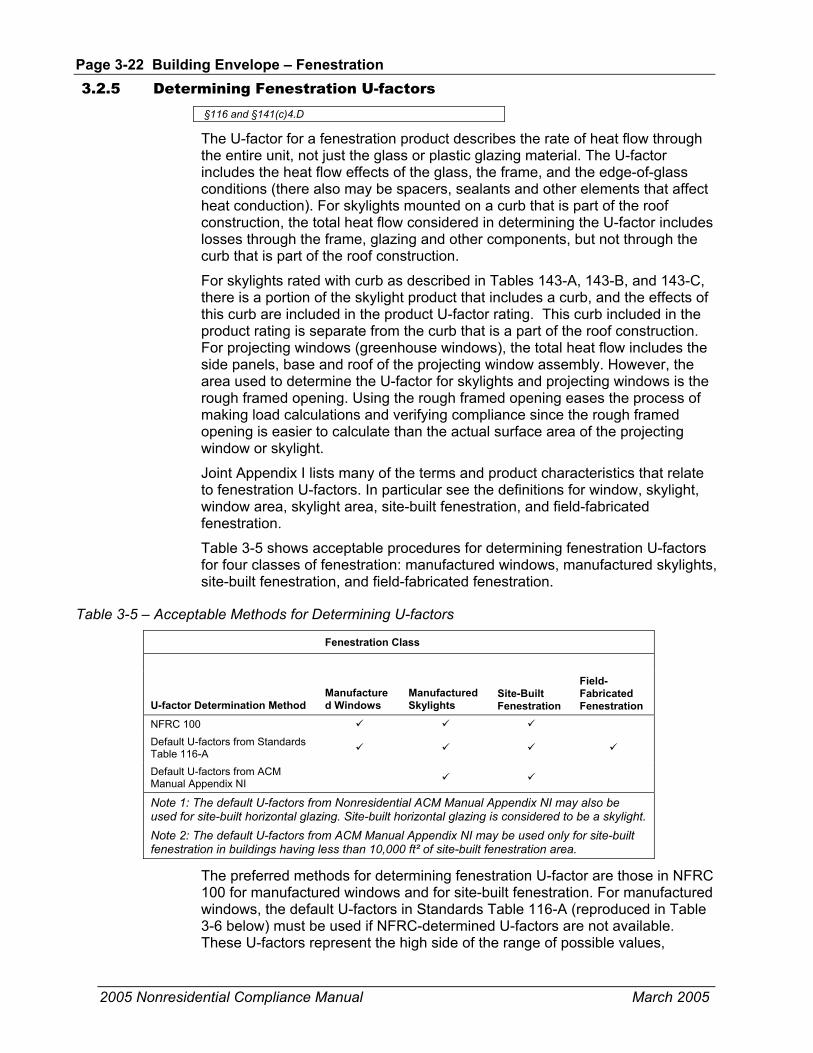
Page 3-22 Building Envelope – Fenestration
2005 Nonresidential Compliance Manual March 2005
3.2.5 Determining Fenestration U-factors §116 and §141(c)4.D
The U-factor for a fenestration product describes the rate of heat flow through the entire unit, not just the glass or plastic glazing material. The U-factor includes the heat flow effects of the glass, the frame, and the edge-of-glass conditions (there also may be spacers, sealants and other elements that affect heat conduction). For skylights mounted on a curb that is part of the roof construction, the total heat flow considered in determining the U-factor includes losses through the frame, glazing and other components, but not through the curb that is part of the roof construction.
For skylights rated with curb as described in Tables 143-A, 143-B, and 143-C, there is a portion of the skylight product that includes a curb, and the effects of this curb are included in the product U-factor rating. This curb included in the product rating is separate from the curb that is a part of the roof construction. For projecting windows (greenhouse windows), the total heat flow includes the side panels, base and roof of the projecting window assembly. However, the area used to determine the U-factor for skylights and projecting windows is the rough framed opening. Using the rough framed opening eases the process of making load calculations and verifying compliance since the rough framed opening is easier to calculate than the actual surface area of the projecting window or skylight.
Joint Appendix I lists many of the terms and product characteristics that relate to fenestration U-factors. In particular see the definitions for window, skylight, window area, skylight area, site-built fenestration, and field-fabricated fenestration.
Table 3-5 shows acceptable procedures for determining fenestration U-factors for four classes of fenestration: manufactured windows, manufactured skylights, site-built fenestration, and field-fabricated fenestration.
Table 3-5 – Acceptable Methods for Determining U-factors
Fenestration Class
U-factor Determination Method Manufactured Windows
Manufactured Skylights
Site-Built Fenestration
Field-Fabricated Fenestration
NFRC 100 Default U-factors from Standards Table 116-A
Default U-factors from ACM Manual Appendix NI
Note 1: The default U-factors from Nonresidential ACM Manual Appendix NI may also be used for site-built horizontal glazing. Site-built horizontal glazing is considered to be a skylight. Note 2: The default U-factors from ACM Manual Appendix NI may be used only for site-built fenestration in buildings having less than 10,000 ft² of site-built fenestration area.
The preferred methods for determining fenestration U-factor are those in NFRC 100 for manufactured windows and for site-built fenestration. For manufactured windows, the default U-factors in Standards Table 116-A (reproduced in Table 3-6 below) must be used if NFRC-determined U-factors are not available. These U-factors represent the high side of the range of possible values,

Building Envelope – Fenestration Page 3-23
2005 Nonresidential Compliance Manual March 2005
thereby encouraging designers to obtain ratings through NFRC procedures, when they are available.
NFRC U-factors are less likely to be available for skylights than they are for windows, there are limited test data can be extended through calculations for skylights. Typically, acrylic skylights must be individually tested for NFRC rating purposes. Since NFRC data might not be available, the default U-factors from ACM Manual Appendix NI may be used for skylights. These values are taken from the ASHRAE Fundamentals (2001) and represent average typical values, as opposed to the values published in Table 116-A in the Standards that are on the high side of the range of typical values. The alternate default U-factors for site-built fenestration in buildings with less than 10,000 ft2 of site-built glazing are also listed in Appendix NI.
The recommended method for determining the U-factor of site-built fenestration systems (curtain walls and storefront systems) is the NFRC 100 (2002) procedure. This requires that a sample of the curtain wall assembly be assembled and tested in an NFRC-approved laboratory. If the building has less than 10,000 ft² of site-built fenestration area, which includes windows, non-opaque doors, and skylights, then U-factors used for compliance for site-built products may instead be selected from ACM Manual Appendix NI, NFRC 100, or Title 24 default values.
For buildings with more than 10,000 ft² of site-built fenestration area, there are two compliance choices with regard to U-factor and labeling of site-built fenestration:
• Go through the NFRC process and obtain a label certificate. This is the option described in §10-111(a)1A.
• Provide a default label certificate using the default U-factors from Standards Table 116-A. This option results in very conservative U-factors.
Field-fabricated fenestration is fenestration assembled on site that does not qualify as site-built fenestration. It includes windows where wood frames are constructed from raw materials at the building site, salvaged windows that do not have an NFRC label or rating, and other similar fenestration items. For this class of fenestration, U-factors must be taken from Standards Table 116-A.
Field-Fabricated Fenestration Product or Exterior Door Field-fabricated fenestration does not include site-assembled frame components that were manufactured elsewhere with the intention of being assembled on site (such as knocked down products, sunspace kits, or curtain walls). For field-fabricated fenestration, the U-factor and solar heat gain coefficient are default values (see Standards Tables 116-A and 116-B).
Exterior doors are doors through an exterior partition. They may be opaque or have glazed area that is less than or equal to one-half of the door area. U-factors for opaque exterior doors are listed in Joint Appendix IV, Table IV.28. Doors with glazing for more than one-half of the door area are treated as fenestration products and must meet all requirements and ratings associated with fenestration.

Page 3-24 Building Envelope – Fenestration
2005 Nonresidential Compliance Manual March 2005
When a door has glazing of less than one-half the door area, the portion of the door with fenestration must be treated as part of the envelope fenestration independent of the remainder of the door area.
A field-fabricated product may become a site-built product if all the requirements for receiving a label certificate required of site-built products are met.
Table 3-6 – Standards Table 116-A Default Fenestration Product U-Factors
FRAME TYPE1
PRODUCT TYPE
SINGLE PANE U-FACTOR
DOUBLE-PANE U-FACTOR2
Metal Operable 1.28 0.79
Metal Fixed 1.19 0.71
Metal Greenhouse/garden window 2.26 1.40
Metal Doors 1.25 0.77
Metal Skylight 1.98 1.3
Metal, Thermal Break Operable N/A 0.66
Metal, Thermal Break Fixed N/A 0.55
Metal, Thermal Break Greenhouse/garden window N/A 1.12
Metal, Thermal Break Doors N/A 0.59
Metal, Thermal Break Skylight N/A 1.11
Nonmetal Operable 0.99 0.58
Nonmetal Fixed 1.04 0.55
Nonmetal Doors 0.99 0.53
Nonmetal Greenhouse/garden windows 1.94 1.06
Nonmetal Skylight 1.47 0.84 1 Metal includes any field-fabricated product with metal cladding. Nonmetal-framed manufactured fenestration products with metal cladding must add 0.04 to the listed U-factor. Nonmetal frame types can include metal fasteners, hardware, and door thresholds. Thermal break product design characteristics are as follows: a. The material used as the thermal break must have a thermal conductivity of not more than 3.6 Btu-inch/hr/ft2/°F, b. The thermal break must produce a gap of not less than 0.210 inch, and c. All metal members of the fenestration product exposed to interior and exterior air must incorporate a thermal break meeting the criteria in Items a. and b. above. In addition, the fenestration product must be clearly labeled by the manufacturer that it qualifies as a thermally broken product in accordance with this standard. Thermal break values shall not apply to field-fabricated fenestration products. 2For all double-glazed fenestration products, adjust the listed U-factors as follows: a. Subtract 0.05 for spacers of 7/16 inch or wider. b. Subtract 0.05 for products certified by the manufacturer as low-E glazing. c. Add 0.05 for products with dividers between panes if spacer is less than 7/16 inch wide. d. Add 0.05 to any product with true divided lite (dividers through the panes).
3.2.6 Determining Relative Solar Heat Gain §143(a)5C
Relative solar heat gain (RSHG) is essentially the same as SHGC, except for the external shading correction. It is calculated by multiplying the SHGC of the fenestration product by an overhang factor. If an overhang does not exist, then the overhang factor is 1.0.
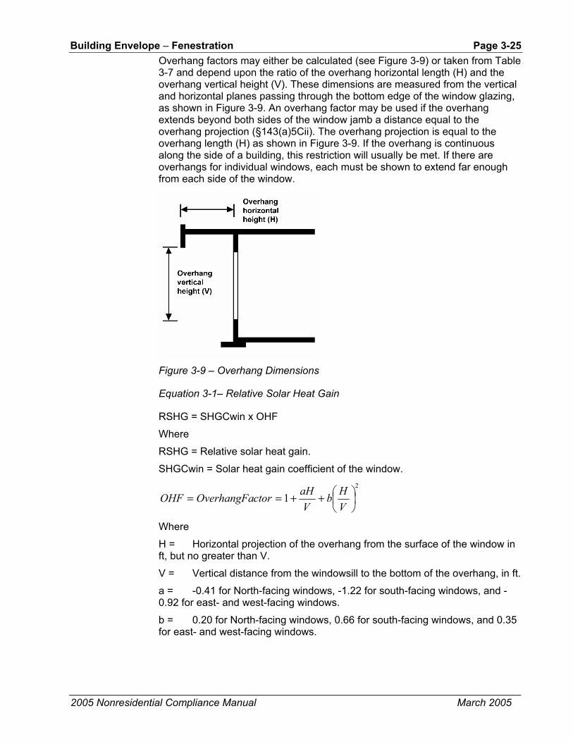
Building Envelope – Fenestration Page 3-25
2005 Nonresidential Compliance Manual March 2005
Overhang factors may either be calculated (see Figure 3-9) or taken from Table 3-7 and depend upon the ratio of the overhang horizontal length (H) and the overhang vertical height (V). These dimensions are measured from the vertical and horizontal planes passing through the bottom edge of the window glazing, as shown in Figure 3-9. An overhang factor may be used if the overhang extends beyond both sides of the window jamb a distance equal to the overhang projection (§143(a)5Cii). The overhang projection is equal to the overhang length (H) as shown in Figure 3-9. If the overhang is continuous along the side of a building, this restriction will usually be met. If there are overhangs for individual windows, each must be shown to extend far enough from each side of the window.
Figure 3-9 – Overhang Dimensions
Equation 3-1– Relative Solar Heat Gain
RSHG = SHGCwin x OHF
Where
RSHG = Relative solar heat gain.
SHGCwin = Solar heat gain coefficient of the window. 2
1
++==
VHb
VaHctorOverhangFaOHF
Where
H = Horizontal projection of the overhang from the surface of the window in ft, but no greater than V.
V = Vertical distance from the windowsill to the bottom of the overhang, in ft.
a = -0.41 for North-facing windows, -1.22 for south-facing windows, and -0.92 for east- and west-facing windows.
b = 0.20 for North-facing windows, 0.66 for south-facing windows, and 0.35 for east- and west-facing windows.

Page 3-26 Building Envelope – Fenestration
2005 Nonresidential Compliance Manual March 2005
Table 3-7 – Overhang Factors
H/V North South East/West 0.00 1.00 1.00 1.00
0.10 0.96 0.88 0.91
0.20 0.93 0.78 0.83
0.30 0.90 0.69 0.76
0.40 0.87 0.62 0.69
0.50 0.85 0.56 0.63
0.60 0.83 0.51 0.57
0.70 0.81 0.47 0.53
0.80 0.80 0.45 0.49
0.90 0.79 0.44 0.46
1.00 or greater 0.79 0.44 0.43
To use Table 3-7, measure the horizontal projection of the overhang (H) and the vertical height from the bottom of the glazing to the shading cut-off point of the overhang (V). Then calculate H/V. Enter the table at that point. If the calculated H/V falls between two values in the Table 3-7, choose the next higher value to the calculated H/V value from the Table. Move across to the column that corresponds to the orientation of the window and find the overhang factor. Note that any value of H/V greater than one has the same overhang factor (for a given orientation) shown in the last row of the table.
Figure 3-10 graphs the overhang factors of the various orientations as a function of H/V. It shows that overhangs have only a minor effect on the north (maximum reduction in SHGC is only about 20%). East, west and south overhangs can achieve reductions of 55%–60%. The benefits of the overhang level off as the overhang becomes large. (Note: this graph is presented only to illustrate the benefits of overhangs.)
Figure 3-10 – Graph of Overhang Factors

Building Envelope – Fenestration Page 3-27
2005 Nonresidential Compliance Manual March 2005
Example 3-4
Question
An east-facing window has glass with a solar heat gain coefficient of 0.71. It has a fixed overhanging eave that extends three ft out from the plane of the glass (H = 3), and is six ft above the bottom of the glass (V = 6). The overhang extends more than three ft beyond each side of the glass and the top of the window is less than two ft vertically below the overhang. What is the RSHG for this window?
Answer
First, calculate H/V. This value is 3 / 6 = 0.50. Next, find the overhang factor from Table 3-7. For east-facing windows, this value is 0.63. Finally, multiply it by the solar heat gain coefficient to obtain the RSHG: 0.63 x 0.71 = 0.45.
3.2.7 Determining Solar Heat Gain Coefficients §141(c)5
The solar heat gain coefficient (SHGC) is a measure of the quantity of solar heat entering a window or skylight; the lower the SHGC, the less solar heat gain. A low SHGC reduces solar heat gains, thereby reducing the amount of air conditioning energy needed to maintain comfort in the building. A low SHGC may also increase the amount of heat needed to maintain comfort in the winter. The technical definition of SHGC is the ratio of solar energy entering the window (or fenestration product) to the amount that is incident on the outside of the window. As with U-factors, the window frame, sash and other opaque components, and type of glazing affect SHGC.
There are four acceptable methods for determining SHGC for use with the Standards (see Table 3-8). The preferred methods are two NFRC procedures: NFRC 200 for manufactured fenestration, which includes manufactured skylights, and NFRC 100 for site-built fenestration, which includes site-built skylights. The NFRC standard for rating the SHGC of tubular daylighting devices (TDD’s or tubular skylights) is appropriate only for attic configurations where the insulation layer is directly on top of the ceiling. For spaces with insulated roofs, use the NFRC or default rating of the top dome only.
A third method is to use the SHGC Defaults from Standards Table 116-B. These values are on the high side and do not account for special coatings and other technologies that may be part of a proposed fenestration product.
The fourth method, applicable only to skylights and site-built fenestration in buildings with less than 10,000 ft2 of site-built fenestration, is to use the procedure defined in ACM Manual Appendix NI. This method allows, under limited conditions, the use of Standards Equation 116-A for determining SHGC. This equation calculates an overall SHGC for the fenestration (SHGCfen) assuming a default framing factor and using the center-of-glass SHGC value (SHGCc) for the glazing from the manufacturer’s literature.
Buildings that have 10,000 ft2 or more of site-built fenestration cannot use the site-built Standards Equation 116-A.
Windows are not allowed SHGC credit for any interior shading such as draperies or blinds. Only exterior shading devices such as shade screens

Page 3-28 Building Envelope – Fenestration
2005 Nonresidential Compliance Manual March 2005
permanently attached to the building or structural components of the building can be modeled for performance standards compliance. Manually operable shading devices cannot be modeled. Only overhangs can be credited using the relative solar heat gain procedure for prescriptive compliance.
Table 3-8 – Methods for Determining SHGC
SHGC Determination Method
Manufactured Windows
Manufactured Skylights Site-Built Fenestration Field-Fabricated Fenestration
NFRC 200 (Note 2) NFRC 100 (2002) Default SHGC values from Standards Table 116-B)
SHGC alternative procedure from ACM Manual Appendix NI. SHGCfen = 0.08 + 0.86 x SHGCc
(Note 1)
Note 1: The SHGC procedure defined in Nonresidential ACM Manual Appendix NI may be used only for site-built fenestration in buildings that have less than 10,000 ft² of site-built fenestration area. Site-built fenestration includes site-built skylights. Note 2: Tubular Daylight Device SHGC rating is appropriate only for insulated ceilings.
3.2.8 Determining Visible Light Transmittance (VLT)
Visible light Transmittance (VLT) is a property of glazing materials that has a varying relationship to SHGC. VLT is the ratio of light that passes through the glazing material to the light that is incident on the outside of the glazing. Light is the portion of solar energy that is visible to the human eye. VLT is an important characteristic of glazing materials, because it affects the amount of daylight that enters the space and how well views through windows are rendered. Glazing materials with a very low VLT have little daylighting benefit and views appear dark, even on bright days. The ideal glazing material for most of California’s summer climates would have a high VLT and a low SHGC. Such a glazing material would allow solar radiation in the visible spectrum to pass while blocking radiation in the infrared and ultraviolet spectrums. Materials that have this quality are labeled “spectrally selective” and have a VLT that is 20% or so higher than the SHGC. Higher VLT can result in energy savings in lighting systems.
The value of VLT for a given material is found in the manufacturer’s literature. VT from NFRC cannot be used in lieu of VLT. For more information on how to determine VLT, refer to Section 5.2.1.4, Daylighting Controls, of this manual.
3.2.9 Determining Site-Built Fenestration Performance (§116, §10-111)
Manufactured fenestration products are factory-assembled as a unit, and the manufacturer is able to assume the burden of testing and labeling. However, with site-built fenestration, multiple parties are responsible. Architects and/or engineers design the basic glazing system by specifying the components, the geometry of the components, and sometimes, the method of assembly. An

Building Envelope – Fenestration Page 3-29
2005 Nonresidential Compliance Manual September 2005
extrusion manufacturer provides the mullions and frames that support the glazing and is responsible for thermal breaks. A glazing manufacturer provides the glazing units, cut to size and fabricated as insulated glass (IG) units. The glazing manufacturer is responsible for tempering or heat strengthening, the tint of the glass, any special coatings, the spacers, and the sealants. A glazing contractor (usually a subcontractor to the general contractor) puts the system together at the construction site or their shop and is responsible for many quality aspects. Predetermining the energy performance of site-built fenestration as a system is more challenging than for manufactured units.
NFRC 100 addresses the special needs of site-built fenestration products. The NFRC procedures are recommended for all site-built fenestration systems or use Table 116-A for large construction projects. Large construction projects are those that have 10,000 ft² or more of site-built fenestration, which includes windows, non-opaque doors, and skylights. The requirement is intended to apply to large office buildings and other nonresidential buildings with large curtain wall systems. Many of the costs for testing and labeling site-built glazing systems are fixed, so the cost per ft2 is lower in larger projects. This is the primary rationale for NFRC testing and labeling.
One of the parties (architect, glazing contractor, extrusion manufacturer, IG fabricator, or glass manufacturer) must take responsibility for testing and labeling of the site-built fenestration system under the most recent NFRC 100 procedure. The responsible party must obtain an NFRC license and establish a relationship with an NFRC certified simulation laboratory, an NFRC certified testing laboratory, and an NFRC certified independent agent (IA). For more information on the licensing process, refer to the NFRC web site at http://www.nfrc.org/.
The responsible party must work with the glazing or curtain wall supplier(s) to carry out the following steps:
• Arrange for an NFRC accredited simulation laboratory to evaluate and determine the thermal performance of each product line.
• Make an arrangement with an NFRC accredited testing laboratory to conduct a validation test on each product line.
• Forward copies of the simulation and test reports to an NFRC-accredited IA for review.
The IA then issues an NFRC Label Certificate that is kept on file in the general contractor’s construction office and posted on-site for review by the building inspector. The NFRC Label Certificate serves the same function as the temporary label that is required for manufactured fenestration products.
It is typical for the glazing contractor to assume responsibility for the team and to coordinate the certification and labeling process. A common procedure is for the design team to include language in the contract with the general contractor that requires that the general contractor be responsible; the general contractor typically assigns this responsibility to the glazing contractor. Once the responsible party has established a relationship with an IA, a simulation laboratory and a testing laboratory, the process works smoothly and should not delay either the design or construction process.

Page 3-30 Building Envelope – Fenestration
2005 Nonresidential Compliance Manual March 2005
It is not necessary to complete the NFRC testing and labeling prior to completing the compliance documentation and filing the building permit application. However, plans examiners should verify that the fenestration performance shown in the plans and specifications and used in the compliance calculations is “reasonable” and achievable. This requires some judgment and knowledge on the part of the plans examiner. Generally, designers will know the type of glass that they plan to use and whether or not the frame has a thermal break or is thermally improved. This information is adequate to consult the default values for U-factor and SHGC in ACM Manual Appendix NI. If the values used for compliance are within 5% of the Appendix NI values, then the values may be considered reasonable for plan check. If the compliance values are outside the 5% range, the plans examiner should request information from the designers to justify the proposed values. It may be necessary for the design team to consult with NFRC simulation laboratories to determine what technologies might be required to achieve the specified level of performance.
After the construction contract is awarded, the glazing contractor or other appropriate party assumes responsibility for getting the simulations and tests made and for obtaining the NFRC Label Certificate. The IA issues a separate label certificate for each “product line.” Each label certificate has the same information as the NFRC temporary label for manufactured products, but includes other information specific to the project such as the name of the glazing manufacturer, the extrusion contractor, the places in the building where the product line is used, and other details. The label certificate remains on file in the construction office for the building inspector to view. After construction is complete, the label certificate should be filed in the building office with the as-built drawings and other operations and maintenance data. This will give building managers the information needed for repairs or replacements.
Example 3-5
Question
A designer is using a U-factor of 0.57 for compliance with a curtain wall system. The glazing system uses two lites of 1/4 in (6mm). glass with a low-e=0.1 coating on the second surface. The air gap is 1/2 in (12 mm). A standard metal frame is proposed for the curtain wall system. Is 0.57 a reasonable U-factor for compliance, and can it reasonably be achieved by the glazing contractor through the NFRC process for site-built fenestration?
Answer
The default U-factor for this glazing combination from ACM Manual Appendix NI is 0.59. The proposed factor of 0.57 is within 5% and should be considered reasonable.
Example 3-6
Question
The envelope and space conditioning system of an office building with 120,000 ft2 of conditioned floor area is being altered. The building has 24,000 ft2 of vertical fenestration. Which of the following scenarios does the NFRC label certificate requirement apply to?
1. Existing glazing remains in place during the alteration.
2. Existing glazing is removed, stored during the alteration period and then re-installed (glazing is not altered in any way).

Building Envelope – Opaque Envelope Insulation Page 3-31
2005 Nonresidential Compliance Manual September 2005
3. Existing glazing is removed and replaced with new site-built glazing with the same dimensions and performance specifications.
4. Existing glazing on the north façade (total area 6000 ft2) is removed and replaced with site-built fenestration.
Answer
NFRC label certificate requirement does not apply to scenarios 1, and 2 but does apply to scenario 3.
1. Requirement does not apply because the glazing remains unchanged and in place.
2. Exception to §116(a) applies in this case (this exception applies to fenestration products removed and reinstalled as part of a building alteration or addition).
3. Use either NFRC Label Certificate or use Table 116-A default values, applies in this case as 24,000 ft2 (more than the threshold value of 10,000 ft2) of new fenestration is being installed.
4. Use either NFRC 100 or the applicable default U-factor set forth in Nonresidential ACM Manual Appendix NI with less than 10,000 ft2 of site-built fenestration.
Defining Product Lines for Site-Built Fenestration Please see NFRC Certified Products Directory and NFRC 100 Combined: Procedures for Determining Fenestration U-factors – http://www.nfrc.org.
3.3 Opaque Envelope Insulation The requirements for opaque surfaces include both mandatory measures and prescriptive requirements.
Sloping surfaces are considered either a wall or a roof, depending on their slope (see Figure 3-11). If the surface has a slope of less than 60° from horizontal, it is considered a roof; a slope of 60° or more is a wall. This definition extends to fenestration products, including the windows in walls and any skylights in roofs.
Figure 3-11 – Slope of a Wall or Window (Roof or Skylight slope is less than 60°) The window is considered part of the wall because the slope is over 60º. Where the slope less than 60º, the glazing indicated as a window would be a skylight.

Page 3-32 Building Envelope – Opaque Envelope Insulation
2005 Nonresidential Compliance Manual March 2005
3.3.1 Mandatory Measures
Certification of Insulation Materials §118(a)
The California Quality Standards for Insulating Materials ensure that insulation sold or installed in the state performs according to the stated R-value and meets minimum quality, health, and safety standards.
Manufacturers must certify that insulating materials comply with California Quality Standards for Insulating Materials (CCR, Title 24, Part 12, Chapters 12-13), which ensure that insulation sold or installed in the state performs according to stated R-values and meets minimum quality, health, and safety standards. Builders may not install the types of insulating materials listed in Table 3-9 unless the product has been thus certified. Builders and enforcement agencies should use the Department of Consumer Affairs Consumer Guide and Directory of Certified Insulation Material to check compliance. (Note: this is not an Energy Commission publication.) If an insulating product is not listed in the most recent edition of the directory, contact the Department of Consumer Affairs, Thermal Insulation Program, at (916) 574-2041.
Table 3-9 – Insulation Materials Requiring Certification
Type Form
Aluminum foil Reflective foil Cellular glass Board form Cellulose fiber Loose fill and spray applied Mineral aggregate Board form Mineral fiber Blankets, board form, loose fill Perlite Loose fill Phenolic Board form Polystyrene Board form, molded extruded Polyurethane Board form and field applied Polyisocyanurate Board form and field applied Urea formaldehyde Foam field applied Vermiculite Loose fill
Urea Formaldehyde Foam Insulation §118(b)
The mandatory measures restrict the use of urea formaldehyde foam insulation. The restrictions are intended to limit human exposure to formaldehyde, which is a volatile organic chemical known to be harmful to humans.
If foam insulation is used that has urea formaldehyde, it must be installed on the exterior side of the wall (not in the cavity of framed walls), and a continuous barrier must be placed in the wall construction to isolate the insulation from the interior of the space. The barrier must be four mil thick polyethylene or equivalent.

Building Envelope – Opaque Envelope Insulation Page 3-33
2005 Nonresidential Compliance Manual March 2005
Flamespread Rating §118(c)
The California Quality Standards for Insulating Materials also require that all exposed installations of faced mineral fiber and mineral aggregate insulations use fire retardant facings that have been tested and certified not to exceed a flame spread of 25 and a smoke development rating of 450. Insulation facings that do not touch a ceiling, wall, or floor surface, and faced batts on the underside of roofs with an air space between the ceiling and facing are considered exposed applications.
Flamespread ratings and smoke density ratings are shown on the insulation or packaging material or may be obtained from the manufacturer.
Insulation over T-bar Ceilings §118(e)
Insulation installed on the top of suspended (T-bar) ceilings with removable ceiling panels may not be used to comply with the efficiency standards unless the installation meets the criteria described in the exception to §118(e)3 below. Insulation may be installed in this location for other purposes such as for sound control, but it will have no value in terms of meeting roof/ceiling insulation requirements of the Standards.
Acceptable insulation installations include placing the insulation in direct contact with a continuous roof or ceiling that is sealed to limit infiltration and exfiltration as specified in §117, including but not limited to placing insulation either above or below the roof deck or on top of a drywall ceiling.
When insulation is installed at the roof in nonresidential buildings, the space between the ceiling and the roof is considered to be either directly or indirectly conditioned space. This space must not include fixed vents or openings to the outdoors or to unconditioned spaces. This space must not be considered an attic for the purposes of complying with CBC attic ventilation requirements. Vents that do not penetrate the roof deck and that are designed for wind resistance for roof membranes are acceptable.
EXCEPTION to §118(e)3: When there are conditioned spaces with a combined floor area no greater than 2,000 ft2 in an otherwise unconditioned building, and when the average height of the space between the ceiling and the roof over these spaces is greater than 12 ft, insulation placed in direct contact with a suspended ceiling with removable ceiling panels shall be an acceptable method of reducing heat loss from a conditioned space and shall be accounted for in heat loss calculations.
U-factors for this exception are found in Joint Appendix IV, Table IV.8.
Demising Walls §118(f)

Page 3-34 Building Envelope – Opaque Envelope Insulation
2005 Nonresidential Compliance Manual March 2005
Demising walls separating conditioned space from enclosed unconditioned space must be insulated with a minimum of R-13 insulation if the wall is a wood- or metal-framed assembly. This requirement applies to buildings meeting compliance under the prescriptive or performance approach. This requirement assures at least some insulation in a wall where an adjoining space may remain unconditioned indefinitely. Demising walls that are constructed of brick, concrete masonry units, or solid concrete are not required to be insulated.
3.3.2 Prescriptive Requirements
The prescriptive requirements include minimum insulation levels for roofs/ceilings, walls, and floors. The requirements are expressed in two ways: a maximum U-factor and a minimum R-value. The U-factor criteria are also given for different classes of construction such as wood- framed, metal-framed, metal building, and mass walls. A roof with metal framing members or a metal deck may comply using the minimum R-value from Standards Tables 143-A, 143-B, and 143-C if a continuous insulation layer with at least that minimum R-value is installed either above the roof deck or between the roof deck and the structural members supporting the roof deck. Alternatively, a roof with metal framing members or a metal deck may comply if 1) a continuous layer of rigid insulation with a minimum R-value of R-10 is installed either above the roof deck or between the roof deck and its structural members, and 2) insulation with a minimum R-value equal to or greater than the applicable value in Standards Table 143-A, Table 143-B, or Table 143-C is installed between the structural members.
The criteria also vary by climate zone and occupancy. Standards Table 143-A has the criteria for nonresidential buildings. Standards Table 143-B has the criteria for high-rise residential buildings and hotel/motel guest rooms. The latter is more stringent because the buildings are assumed to be heated and cooled continuously. Standards Table 143-C has criteria for relocatable public school buildings. These criteria are climate independent, since manufacturers often do not know who will buy their product and which climate zone it will be installed in. The nonresidential and residential criteria are expressed for the five climate regions described in the overview section of this chapter.
Exterior Roofs and Ceilings §143(a)1.
Exterior roofs or ceilings can meet the prescriptive requirements in one of two ways: have the required R-value of insulation (applicable only if the roof does not have metal framing or a metal deck) or have an assembly U-factor that meets the maximum U-factor criterion (see Table 3-10). For most nonresidential buildings, a U-factor of 0.076 or R-value of R-11 is required in the south coast climates (zones 6-9) and U-factor of 0.051 or non-metal R-19 is required in other locations. For high-rise residential buildings and hotel/motel guest rooms, a U-factor of 0.051 or R-value of R-19 (for non-metal framing or deck) is required in the middle coast and south coast climates (zones 3 through 9) and U-factor of 0.036 or R-30 for non-metal is required in other California locations. For relocatable public school buildings, U-factor of 0.051 or R-19 for non-metal is required in all climate zones.

Building Envelope – Opaque Envelope Insulation Page 3-35
2005 Nonresidential Compliance Manual March 2005
Wet Insulation Systems
Wet insulation systems are roofing systems where the insulation is installed above the roof’s waterproof membrane. Water can penetrate this insulation material and have an effect on the energy performance of the roofing assembly in wet and cool climates. In climate zones 1 and 16, the insulating R-value of continuous insulation materials installed above the roof’s waterproof membrane must be multiplied times 0.8 before choosing the table column in Joint Appendix IV for determining assembly U-factor. See the footnotes for Tables IV.1 through IV.7 in the Joint Appendices.
Table 3-10 – Roof/Ceiling Requirements Summary from Standards Tables 143-A and 143-B
Climate Zones Roof/Ceiling Space Type Criterion* 1,16 3-5 6-9 2,10-13 14, 15
Nonresidential U-factor 0.051 0.051 0.076 0.051 0.051 R-value 19 19 11 19 19
U-factor 0.036 0.051 0.051 0.036 0.036 Residential High-rise R-value 30 19 19 30 30 U-factor 0.051 0.051 0.051 0.051 0.051 Relocatable Public School Buildings R-value 19 19 19 19 19
*U-factors are the actual conductance of the entire assembly. R-values refer to the nominal R-value of the insulation within the framing. NOTE: R-value cannot be used for compliance when the roof has metal framing members or a metal deck unless additional rigid insulation is installed. See §143 (a) 1 C.
For roof structures where a metal deck is in direct contact with metal supporting members, the R-value method of compliance may be used only if the required insulation R-value is continuous over the top of the metal deck or continuous and installed between the metal supports and the metal deck. For metal building roofs, R-10 continuous (rigid) insulation may be used across the supports with insulation of the designated R-value used between the framing.
Figure 3-12 shows acceptable means of meeting the R-value criteria for metal roofs.
The mandatory measures prohibit insulation from being installed directly over suspended ceilings (see previous section), except for limited circumstances.
When the U-factor compliance method is used, U-factors must be selected from Joint Appendix IV.

Page 3-36 Building Envelope – Opaque Envelope Insulation
2005 Nonresidential Compliance Manual March 2005
Figure 3-12 – Acceptable Metal to Metal Roof Constructions
Exterior Walls §143(a)2
Exterior walls can meet the component requirements by either using a construction that has an assembly U-factor lower than the specified criteria as shown in Table 3-9, or installing the required R-value of insulation (Table 3-11).
For nonresidential buildings, R-11 insulation is required for the middle and south coasts (zones 3 through 9) and R-13 is required in other climate zones. For residential buildings and hotel/motel guest rooms, R-11 is required for the middle and south coast areas (zones 3 through 9); R-13 is required for the valley and desert climates (zones 2 and 10 through 15); and R-19 is required for the cold climates (zones 1 and 16). For public school buildings, R-13 is required in all climate zones.

Building Envelope – Opaque Envelope Insulation Page 3-37
2005 Nonresidential Compliance Manual March 2005
Table 3-11 – Wall Requirements Summary from Standards Tables 143-A and 143-B
Climate Zones Wall Requirements Space Type Criterion
1,16 3-5 6-9 2,10-13 14, 15
Nonresidential R-value or 13 11 11 13 13
U-factor
Wood frame 0.102 0.110 0.110 0.102 0.102
Metal frame 0.217 0.224 0.224 0.217 0.217
Metal building 0.113 0.123 0.123 0.113 0.113
Mass/7.0≤ HC<15.0 0.330 0.430 0.430 0.430 0.430
Mass/15.0≤HC 0.360 0.650 0.690 0.650 0.410
Other 0.102 0.110 0.110 0.102 0.102
Residential High-rise
R-value 19 11 11 13 13
U-factor
Wood frame 0.074 0.110 0.110 0.102 0.102
Metal frame 0.183 0.224 0.224 0.217 0.217
Metal building 0.061 0.123 0.123 0.113 0.113
Mass/7.0≤ HC<15.0 0.330 0.430 0.430 0.430 0.430
Mass/15.0≤HC 0.360 0.650 0.690 0.650 0.410
Other 0.074 0.110 0.110 0.102 0.102
Public School Buildings
R-value 13 13 13 13 13
U-factor
Wood frame 0.102 0.102 0.102 0.102 0.102 Metal frame 0.261 0.261 0.261 0.261 0.261 Metal building 0.061 0.061 0.061 0.061 0.061 Mass/7.0≤ HC<15.0 0.330 0.330 0.330 0.330 0.330
Other 0.102 0.102 0.102 0.102 0.102
The U-factor criteria for walls depend on the class of construction. U-factors used for compliance must be selected from Joint Appendix IV. There are six classes of wall constructions: wood frame, metal frame, metal building walls, medium mass, high mass, and other (Figure 3-13). The “other” category is used for any wall type that does not fit into one of the other five wall classes. The following bullets give more information.
• Wood-framed walls. As defined by the International Building Code, Type IV buildings typically have wood-framed walls. Framing members typically consist of 2x4 or 2x6 framing members spaced at 24 in. or 16 in. OC. Composite framing members and engineered wood products also qualify as wood-framed walls if the framing members are non-metallic. Structurally insulated panels (SIPS) are another construction type that qualifies as wood framed. SIPS panels typically consist of rigid foam insulation sandwiched between to layers of oriented strand board (OSB). Joint Appendix IV, Table IV.9 has data for conventional wood-framed walls and Table IV.10 has data for SIPS panels.

Page 3-38 Building Envelope – Opaque Envelope Insulation
2005 Nonresidential Compliance Manual March 2005
• Metal-framed walls. Many nonresidential buildings and high-rise residential buildings require non-combustible construction, and this is achieved with metal-framed walls. Often metal-framed walls are not structural and are used as infill panels in rigid framed steel or concrete buildings. The U-factor criteria are higher for metal-framed walls (compared to wood-framed walls) because the metal framing members are more conductive. From Joint Appendix IV, Table IV.11 has data for metal-framed walls.
• Metal building walls. Metal building walls consist of a metal building skin that is directly attached to metal framing members. The framing members are typically positioned in a horizontal direction and spaced at about 4 ft. A typical method of insulating metal buildings walls is to drape the insulation over the horizontal framing members and to compress the insulation when the metal exterior panel is installed. Table IV.16 from Joint Appendix IV has data for metal building walls.
• Low mass walls. Low mass walls have a heat capacity (HC) greater or equal to 7.0 but less than 15.0 Btu/ºF-ft². See the definition below for heat capacity. From Joint Appendix IV, Tables IV.12 and IV.13 have U-factor, C-factor, and heat capacity data for hollow unit masonry walls, solid unit masonry and concrete walls, and concrete sandwich panels.
• High mass walls have an HC equal to or greater than 15.0 Btu/ºF-ft². See Joint Appendix IV for HC data on mass walls.
• Spandrel panels and glass curtain walls. See Joint Appendix IV, Table IV.15 for U-factor data.
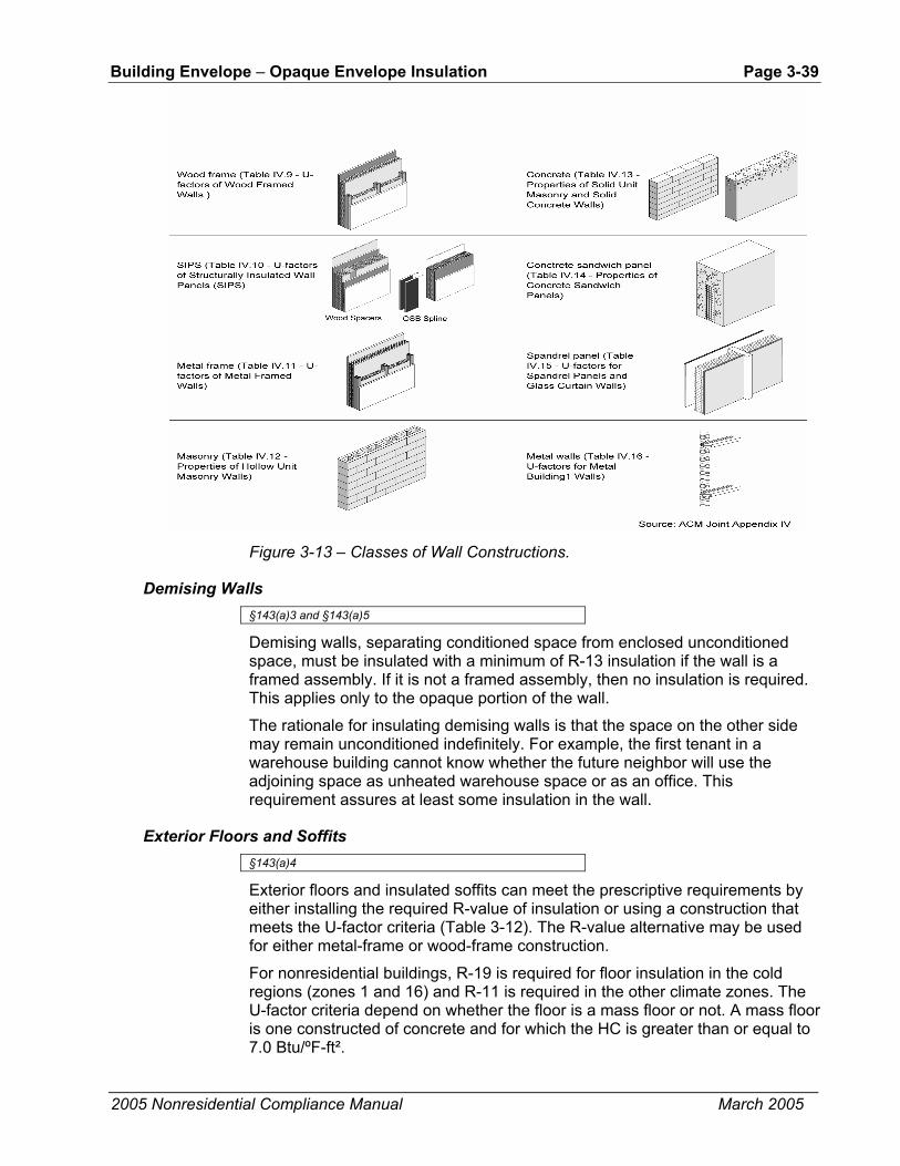
Building Envelope – Opaque Envelope Insulation Page 3-39
2005 Nonresidential Compliance Manual March 2005
Figure 3-13 – Classes of Wall Constructions.
Demising Walls §143(a)3 and §143(a)5
Demising walls, separating conditioned space from enclosed unconditioned space, must be insulated with a minimum of R-13 insulation if the wall is a framed assembly. If it is not a framed assembly, then no insulation is required. This applies only to the opaque portion of the wall.
The rationale for insulating demising walls is that the space on the other side may remain unconditioned indefinitely. For example, the first tenant in a warehouse building cannot know whether the future neighbor will use the adjoining space as unheated warehouse space or as an office. This requirement assures at least some insulation in the wall.
Exterior Floors and Soffits §143(a)4
Exterior floors and insulated soffits can meet the prescriptive requirements by either installing the required R-value of insulation or using a construction that meets the U-factor criteria (Table 3-12). The R-value alternative may be used for either metal-frame or wood-frame construction.
For nonresidential buildings, R-19 is required for floor insulation in the cold regions (zones 1 and 16) and R-11 is required in the other climate zones. The U-factor criteria depend on whether the floor is a mass floor or not. A mass floor is one constructed of concrete and for which the HC is greater than or equal to 7.0 Btu/ºF-ft².

Page 3-40 Building Envelope – Opaque Envelope Insulation
2005 Nonresidential Compliance Manual March 2005
Table 3-12 – Floor/Soffit Requirements Summary from Standards Tables 143-A and 143-B
Climate Zones Floor/Soffit Space Type Criterion 1,16 3-5 6-9 2,10-13 14, 15
R-value or 19 11 11 11 11
U-factor
Mass/7.0≤HC 0.090 0.139 0.139 0.090 0.139
Nonresidential
Other 0.048 0.071 0.071 0.071 0.071
R-value 19 11 11 11 11
U-factor
Mass/7.0≤HC 0.090 0.139 0.139 0.090 0.090
Other 0.048 0.071 0.071 0.071 0.071
Residential High-rise
Raised concrete R-value 8 * * * *
R-value 19 19 19 19 19
U-factor 0.048 0.048 0.048 0.048 0.048 Wood-frame 0.107 0.107 0.107 0.107 0.107 Metal-frame 0.261 0.261 0.261 0.261 0.261 Metal Building 0.061 0.061 0.061 0.061 0.061
Mass/7.0≤HC 0.330 0.330 0.330 0.330 0.330
Relocatable Public School Buildings
Other 0.102 0.102 0.102 0.102 0.102
* Required insulation levels for concrete raised floors are R-8 in Climate Zones 2, 11, 13, and 14; R-4 in Climate Zones 12 and 15, and none in Climate Zones 3 through 10.
For high-rise residential buildings and hotel/motel guest rooms, R-19 floor insulation is required for the cold regions (zones 1 and 16) and R-11 is required in the other climate zones. For relocatable public school buildings, R-19 is required in all climate zones. The U-factor criteria for concrete raised floors depend on whether the floor is a mass floor or not. A mass floor is one constructed of concrete and for which the heat capacity is greater than or equal to 7.0 Btu/ºF-ft².
Insulation levels for nonresidential and high-rise residential concrete raised floors with HC ≥ 7.0 using U-factor for compliance from Joint Appendix IV, Table IV.25, are equivalent to R-8 continuous insulation in climate zones 1, 2, 10 through 13, and 16; and R-4 in climate zones 3 through 9, 14 and 15. The performance method of compliance for high-rise residential concrete raised floors is based on the U-factors in Standards Table 143-B.
Insulation levels for high-rise residential concrete raised floors using R-value for compliance are R-8 continuous insulation underneath in climate zones 1, 2, 11, 13, and 14; and R-4 in climate zones 12 and 15, with no insulation required in Climate zones 3 through 10.
Table IV.25 from Joint Appendix IV is used with mass floors while Tables IV.20 through IV.24 are used for non-mass floors. See also Figure 3-14.

Building Envelope – Opaque Envelope Insulation Page 3-41
2005 Nonresidential Compliance Manual March 2005
Figure 3-14 – Requirements for Floor/Soffit Surfaces
Figure 3-15 – Classes of Floor Constructions.
Exterior Doors §143(a)7
There are no prescriptive requirements for exterior doors. Glazing in doors, however, must be included in all fenestration calculations. When glazing exceeds one-half of the area of the door, it is defined as a window in the Standards, and the entire door area is modeled as a fenestration unit. If the glazing area is less than half the door area, the glazing can be modeled as the glass area plus 2 inches in each direction of the opaque door surface (to account for a frame). However, exterior doors are a part of the gross exterior wall area and must be considered when calculating the window-wall-ratio.
Table IV.28 from Joint Appendix IV has U-factors for exterior doors.

Page 3-42 Building Envelope – Cool Roofs
2005 Nonresidential Compliance Manual March 2005
3.4 Cool Roofs The term “cool roof” refers to an outer layer or exterior surface of a roof that has high solar reflectance and high emittance and reduces heat gain into a building. As the term implies, the temperature of a cool roof is lower on hot sunny days than for a conventional roof, reducing cooling loads and the energy required to provide air conditioning.
The benefit of a high reflectance is obvious: while dark surfaces absorb the sun’s energy (visible light, invisible infrared. and ultraviolet radiation) and become hot, light-colored surfaces reflect solar energy and stay cooler. However, high emittance is also important. Emittance refers to the ability of heat to escape from a surface once it is absorbed. Surfaces with low emittance (usually shiny metallic surfaces) contribute to the transmission of heat into the roof components under the roof surface, while surfaces with high emittance allow heat to escape through radiation to the sky.
There are several ways to achieve the high emittance required to qualify as a cool roof. One of the best methods is to use a single ply roofing membrane with high emittance properties as an integral part of the material. Another approach is to apply a coating to the surface of a conventional roof membrane such as modified bitumen or a mineral cap sheet. Metal roofs can qualify as cool roofs by using an industrial grade coating that has high reflectance and high emittance.
3.4.1 Mandatory Measures
The mandatory measures require that cool roofs be tested and labeled by the Cool Roof Rating Council and that liquid applied products meet minimum standards for performance and durability. Note that installing cool roofs is not a mandatory measure.
Rating and Labeling §10-113
When cool roofs are used for compliance, they must be tested and labeled by the Cool Roof Rating Council (CRRC). The CRRC is the supervisory entity responsible for certifying cool roof products. The CRRC test procedure is documented in CRRC-1, the CRRC Product Rating Program Manual. This test procedure includes tests for both reflectance and emittance.
The minimum label size and font size of the CRRC label are shown below (Figure 3-16). Please note that the CRRC label (an example of which is shown below) may only be used in accordance with CRRC program guidelines.

Building Envelope – Cool Roofs Page 3-43
2005 Nonresidential Compliance Manual March 2005
Initial Weathered Solar Reflectance 0.00 Pending Thermal Emittance 0.00 Pending
SM Rated Product ID XXXXX Licensed Manufacturer ID XXXXX Classification Production Line
Cool Roof Rating Council ratings are determined for a fixed set of conditions, and may not be appropriate for determining seasonal energy performance. The actual effect of solar reflectance and thermal emittance on building performance may vary. Manufacturer of product stipulates that these ratings were determined in accordance with the applicable Cool Roof Rating Council procedures.
Figure 3-16 – Sample CRRC Label
Performance Requirements for Field Applied Liquid Coatings §118(i)3, Table 118-C
There are a number of qualifying liquid products, including elastomeric coatings and white acrylic coatings. The Standards specify minimum performance and durability requirements for field applied liquid coatings. Please note that these requirements do not apply to industrial coatings that are factory-applied, such as metal roof panels. The requirements address elongation, tensile strength, permeance, and accelerated weathering. The requirements depend on the type of coating and are described in greater detail below:
Aluminum-Pigmented Asphalt Roof Coatings
Aluminum-pigmented coatings are silver-colored coatings that are commonly applied to modified bitumen and other roofing products. The coating has aluminum pigments that float to the top surface of the coating while it is setting, providing a shiny and reflective surface. Because of the shiny surface and the physical properties of aluminum, these coatings have an emittance below 0.75, which is the minimum rating for prescriptive compliance. The overall envelope approach is typically used to achieve compliance with these coatings.
This class of field-applied liquid coatings must be manufactured in accordance with ASTM D28244 Standard Specification for Aluminum-Pigmented Asphalt Roof Coatings, Nonfibered, Asbestos Fibered, and Fibered without Asbestos, or ASTM D6848, Standard Specification for Aluminum Pigmented Emulsified
4 1.1 This specification covers asphalt-based, aluminum roof coatings suitable for
application to roofing or masonry surfaces by brush or spray.
1.2 The values stated in SI units are to be regarded as the standard. The values in parentheses are for information only.
1.3 The following precautionary caveat pertains only to the test method portion, Section 8, of this specification: This standard does not purport to address all of the safety concerns, if any, associated with its use. It is the responsibility of the user of this standard to establish appropriate safety and health practices and determine the applicability of regulatory limitations prior to use.

Page 3-44 Building Envelope – Cool Roofs
2005 Nonresidential Compliance Manual March 2005
Asphalt Used as a Protective Coating for Roofing, and installed in accordance with ASTM D38055, Standard Guide for Application of Aluminum-Pigmented Asphalt Roof Coatings. ASTM D2824, Standard Specification for Aluminum-Pigmented Asphalt Roof Coatings, Nonfibered, Asbestos Fibered, and Fibered without Asbestos, covers asphalt-based aluminum roof coatings suitable for application to roofing or masonry surfaces by brush or spray.
Cement-Based Roof Coatings
This class of coatings consists of a layer of cement and has been used for a number of years in the central valley of California and in other regions. These coatings may be applied to almost any type of roofing product.
Cement-based coatings must be manufactured to contain no less than 20% Portland cement and meet the requirements of ASTM D8226, Standard Practice for Filtered Open-Flame Carbon-Arc Exposures of Paint and Related Coatings. When installed over a rock or gravel surface, the coating must be applied at a thickness of at least 200 dry mils (5 mm). The coatings must be applied at a minimum thickness of 30 mils (0.8 mm) when installed on a mineral cap sheet surface and 40 mils (1 mm) when installed over a metal surface.
Other Field-Applied Liquid Coatings
Other field-applied liquid coatings include elastomeric and acrylic based coatings. These coatings must be applied with a minimum thickness of 20 dry mils (0.5 mm) across the entire surface and be tested to meet a number of performance and durability requirements as specified in Table 118-C of the Standards.
5 1.1 This guide covers the application methods for Specification D 2824 Aluminum-
Pigmented Asphalt Roof Coatings, Non-Fibered (Type I), Asbestos Fibered (Type II), and Fibered without Asbestos (Type III), for application on asphalt built-up roof membranes, modified bitumen roof membranes, bituminous base flashings, concrete surfaces, metal surfaces, emulsion coatings, and solvent-based coatings. This guide does not apply to the selection of a specific aluminum-pigmented asphalt roof coating type for use on specific projects.
1.2 The values stated in SI units are to be regarded as the standard. The values given in parentheses are for information only.
1.3 This standard does not purport to address all of the safety concerns, if any, associated with its use. It is the responsibility of the user of this standard to establish appropriate safety and health practices and determine the applicability of regulatory limitations prior to use. Specific precautionary statements are given in Section 4.
6 1.1 This guide is intended for the evaluation of clear and pigmented coatings designed for use on rigid or semirigid plastic substrates. Coated film and sheeting are not covered by this guide.
1.2 This standard does not purport to address all of the safety concerns, if any, associated with its use. It is the responsibility of the user of this standard to establish appropriate safety and health practices and determine the applicability of regulatory limitations prior to use.
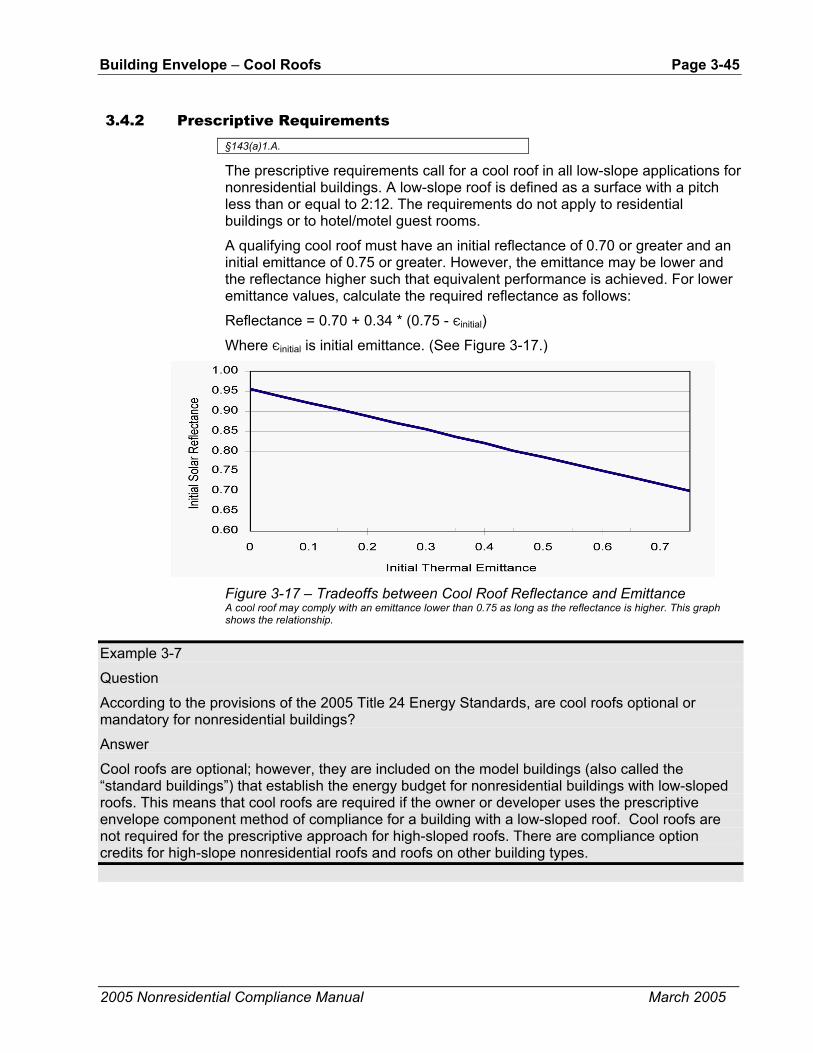
Building Envelope – Cool Roofs Page 3-45
2005 Nonresidential Compliance Manual March 2005
3.4.2 Prescriptive Requirements §143(a)1.A.
The prescriptive requirements call for a cool roof in all low-slope applications for nonresidential buildings. A low-slope roof is defined as a surface with a pitch less than or equal to 2:12. The requirements do not apply to residential buildings or to hotel/motel guest rooms.
A qualifying cool roof must have an initial reflectance of 0.70 or greater and an initial emittance of 0.75 or greater. However, the emittance may be lower and the reflectance higher such that equivalent performance is achieved. For lower emittance values, calculate the required reflectance as follows:
Reflectance = 0.70 + 0.34 * (0.75 - Єinitial)
Where Єinitial is initial emittance. (See Figure 3-17.)
Figure 3-17 – Tradeoffs between Cool Roof Reflectance and Emittance A cool roof may comply with an emittance lower than 0.75 as long as the reflectance is higher. This graph shows the relationship.
Example 3-7
Question
According to the provisions of the 2005 Title 24 Energy Standards, are cool roofs optional or mandatory for nonresidential buildings?
Answer
Cool roofs are optional; however, they are included on the model buildings (also called the “standard buildings”) that establish the energy budget for nonresidential buildings with low-sloped roofs. This means that cool roofs are required if the owner or developer uses the prescriptive envelope component method of compliance for a building with a low-sloped roof. Cool roofs are not required for the prescriptive approach for high-sloped roofs. There are compliance option credits for high-slope nonresidential roofs and roofs on other building types.

Page 3-46 Building Envelope – Cool Roofs
2005 Nonresidential Compliance Manual March 2005
Example 3-8
Question
Must all roofing materials used in California, whether cool materials or not, be certified by CRRC and labeled accordingly?
Answer
It depends on if and how they are being used for energy compliance. If you are using the prescriptive envelope component approach, the answer is yes; the roof must be certified and labeled by CRRC for nonresidential low-sloped roofs. However, to receive compliance credit using the prescriptive overall envelope approach or the performance approach, obtain a CRRC certification, OR use a default reflectance of 0.10. That is, the answer to the question is no if you use the default reflectance for a particular roofing material. (The default reflectance is different for roofs other than low-sloped nonresidential roofs; see Question 3-15.)
Example 3-9
Question
When re-roofing with gravel, must the roof meet cool roof requirements? Is CRRC certification required?
Answer
Not necessarily. Roof recoverings allowed by the California Building Code do not have to meet the cool roof requirements, and a CRRC certification is not required, if ALL of the following are true:
1. The existing roof is a rock or gravel surface;
2. The new roof is a rock or gravel surface;
3. There is no removal of existing layers of roof coverings;
4. There is no recoating with a liquid-applied coating; and
5. There is no installation of recover board, rigid insulation, or other substrate.
Example 3-10
Question
In reroofing, is existing roofing that is a rock or gravel surface equivalent to a gravel roof over an existing cap sheet and therefore may it qualify for the exception discussed in the previous question?
Answer
No, the two roofs are not equivalent and therefore the gravel roof over existing cap sheet may not qualify for the exception.
Example 3-11
Question
Do the Title 24 Energy Standards address high-slope residential roofs? In other words, do shingles need to be certified to meet emittance of 0.30? What about high-slope apartment complexes that are residential but not single family homes?

Building Envelope – Cool Roofs Page 3-47
2005 Nonresidential Compliance Manual March 2005
Answer
The Standards offer compliance credits for these other roofs. The same reflectance, emittance and coating performance requirements apply for these other roofs if they are to receive credit. Roofing materials such as asphalt shingles need to be CRRC certified to meet required emittance and reflectance levels. Note that clay or cement roofing tiles have to meet a reflectance of only 0.40 to gain compliance credit for high-sloped roofs on low-rise residential buildings.
Example 3-12
Question
Can I use solar reflectance and thermal emittance data generated by any nationally recognized and well-respected laboratory in lieu of CRRC ratings? Can in-house testing by the manufacturer be used to qualify my product?
Answer
Only CRRC ratings can be used to establish cool roof product qualification in Title 24 compliance. The CRRC process requires use of a CRRC accredited laboratory under most circumstances, an "Accredited Independent Testing Laboratory (AITL) defined by the CRRC program. Any testing laboratory can become an AITL by following the CRRC accreditation process and satisfying the requirements. The roster of CRRC accredited laboratories is posted on the CRRC website (http://www.coolroofs.org).
Example 3-13
Question
Is aged reflectance a consideration in the cool roof requirements?
Answer
No, compliance is based strictly on initial reflectance.
Example 3-14
Question
Can the reflectance and emittance requirements of Energy Star Cool Roofs be substituted for the Title 24 Energy Standards requirements?
Answer
No. At this time, Energy Star Cool Roofs have only reflectance requirements and no emittance requirements, so Energy Star Cool Roofs do not automatically qualify as cool roofs under Title 24. Only cool roofs certified by CRRC qualify as cool roofs under Title 24 at this time.
Example 3-15
Question
Can I claim to have a cool roof, or can I get anything higher than a default reflectance, if my roof does not meet the field-applied coating performance requirements of Title 24 Energy Standards?
Answer
No, you cannot claim to have a cool roof and you cannot claim higher energy credits if your roof does not meet the coating performance requirements of Title 24 for field-applied coatings.
Page 3-48 Building Envelope – Cool Roofs
2005 Nonresidential Compliance Manual March 2005
Example 3-16
Question
Is the default reflectance for a non-CRRC certified/labeled roof or for one that doesn't meet the coating performance requirements different for nonresidential low-sloped roofs than for other roofs?
Answer
Yes, the default reflectance for nonresidential low-sloped roofs is 0.10 and for other roofs is 0.30.
Example 3-17
Question
Aren’t cool roofs expensive?
Answer
Not necessarily. Our research shows that the cost of a cool roof compared to a non-cool roof can be the same (no difference in price) or slightly higher per square foot for the cool roof, depending on lots of particulars. Our analyses showed cool roofs to be cost-effective over the life cycle of the roofing material in all 16 of California’s climate zones.
Example 3-18
Question
With a reflective, emissive roof (a cool roof), does a building lose the advantage of solar heat gain through the roof in the cold months? Will my heating bills increase?
Answer
In some months in some climate zones, the sun’s heat could provide some heat gain into the building through a low-sloped roof. Taking that gain away with a cool roof still results in a net gain in comfort and energy bills over the course of a year, because the hot-weather benefits of reducing air conditioning needs generally outweigh (in some cases, GREATLY outweigh) the solar gain in winter. In some buildings with a cool roof, there may be a slight increase in the need for space heating in the colder months.
Example 3-19
Question
How does a product get CRRC cool roof certification?
Answer
Any party wishing to have a product or products certified by CRRC should contact CRRC to get started - call toll-free (866) 465-2523 from inside the US or (510) 482-4420, ext 215 or email [email protected]. CRRC staff will walk interested parties through the procedures. In addition, CRRC publishes the procedures in "CRRC-1 Program Manual," available for free on http://www.coolroofs.org or by calling CRRC. However, working with CRRC staff is strongly recommended.
Example 3-20
Question
I understand reflectance, but what is emittance?

Building Envelope – Infiltration and Air Leakage Page 3-49
2005 Nonresidential Compliance Manual March 2005
Answer
Even a material that reflects the sun’s energy will still absorb some of that energy as heat; there are no perfectly reflecting materials being used for roofing. That absorbed heat undergoes a physical change (an increase in wavelength, for readers who remember physics) and is given off – emitted – to the environment in varying amounts by various materials and surface types. This emittance is given a unitless value between 0 and 1, and this value represents a comparison (ratio) between what a given material or surface emits and what a perfect blackbody emitter (again, recall physics) would emit at the same temperature.
A higher emittance value means more energy is released from the material or surface; scientists refer to this emitted energy as thermal radiation (as compared to the energy from the sun, solar radiation, with shorter wavelength). Emittance is a measure of the relative efficiency with which a material, surface, or body can cool itself by radiation. Lower-emitting materials become relatively hotter for not being able to get rid of the energy, which is heat. Roof materials with low emittance therefore hold onto more solar energy as heat, get hotter than high-emittance roofs, and with help from the laws of physics, offer greater opportunity for that held heat to be given off downward into the building through conduction. More heat in the building increases the need for air conditioning for comfort. A cool roof system that reflects solar radiation (has high reflectance) and emits thermal radiation well (has high emittance) will result in a cooler roof and a cooler building with lower air-conditioning costs.
Example 3-21
Question
Do alterations to the roof of an unconditioned building trigger cool roof requirements?
Answer
No, alterations to the roof of an unconditioned building do not trigger cool roof requirements. In general, the lighting requirements are the only requirements applicable for both newly constructed and altered unconditioned buildings; this includes §143(c), the skylight requirements. Building envelope (other than skylight requirements) and mechanical requirements do not apply to unconditioned buildings.
3.5 Infiltration and Air Leakage
3.5.1 Fenestration and Doors
See in Section 3.2.1.
3.5.2 Joints and Openings §117
All joints and other openings in the building envelope that are potential sources of air leakage must be caulked, gasketed, weather-stripped, or otherwise sealed to limit air leakage into or out of the building. This applies to penetrations for pipes and conduits, ducts, vents, and other openings. It means that all gaps between wall panels, around doors, and other construction joints must be well sealed. Ceiling joints, lighting fixtures, plumbing openings, doors,

Page 3-50 Building Envelope – Relocatable Public School Buildings
2005 Nonresidential Compliance Manual March 2005
and windows should all be considered as potential sources of unnecessary energy loss due to infiltration.
No special construction requirements are necessary for suspended (T-bar) ceilings provided they meet the requirements of §118 (e). See Section 3.3.1. Standard construction is adequate for meeting the infiltration/exfiltration requirements.
3.6 Relocatable Public School Buildings Table 143-C ACM Manual Appendix ND
Public school building design is defined by two prescriptive requirements, listed in Tables 143-A and 143-C of the Standards, covering climate-specific public school buildings as well as relocatable public school buildings that can be installed in any climate. Building envelopes must meet the prescriptive requirements in §143 and lighting power requirements in §146. For additional design requirements, refer to §143 and Nonresidential ACM Manual Appendix ND. Manufacturers must certify compliance and provide documentation according to the chosen method of compliance. Performance compliance calculations must be performed for multiple orientations, each model using the same proposed design energy features rotated through 12 different orientations and different climate zones (ACM Manual Appendix ND). Also see §141(d), §149(b)2 NOTE, and Nonresidential ACM Manual Table N2-1 for public school buildings requirements. §141(d) Performance
Relocatable Public School Buildings. When the manufacturer/builder certifies a relocatable public school building for use in any climate zone, the building must be designed and built to meet the energy budget for the most severe climate zones as specified in the Nonresidential ACM Manual, assuming the prescriptive envelope criteria in TABLE 143-C. When the manufacturer/builder certifies that the relocatable building is manufactured for use in specific climate zones and that the relocatable building can not be lawfully used in other climate zones, the energy budget must be met for each climate zone that the manufacturer/building certifies, assuming the prescriptive envelope criteria in TABLE 143-A, including the non-north window RSHG and skylight SHGC requirements for each climate zone. The energy budget and the energy use of the proposed building must be determined using the multiple orientation approach specified in the Nonresidential ACM Manual. The manufacturer/builder shall meet the requirements for identification labels specified in section 143 (a) 8.
Manufacturers may certify the relocatable classrooms for multiple orientations or for compliance for all climate zones statewide. Since relocatable public school buildings could be positioned in any orientation, it is necessary to perform compliance calculations for multiple orientations. Each model with the same proposed design energy features shall be rotated through 12 different orientations either in climate zones 14, 15 and 16 for relocatables showing statewide compliance or in the specific climate zones that the manufacturer proposes for the relocatable to be allowed to be installed, i.e., the building with the same proposed design energy features is rotated in 30 degree increments

Building Envelope – Overall Envelope Approach Page 3-51
2005 Nonresidential Compliance Manual March 2005
and shall comply in each case. Approved compliance programs shall automate the rotation of the building and reporting of the compliance results to insure it is done correctly and uniformly and to avoid unnecessary documentation.
3.7 Overall Envelope Approach §143(b)
The overall envelope approach offers greater design flexibility. It allows the designer to make trade-offs between many of the building envelope components. For example, if a designer finds it difficult to insulate the walls to a level adequate for meeting the wall component U-factor requirement, then the insulation level in a roof or floor or the performance of a window component could be increased to offset the under-insulated wall. The same holds true for glazing. If a designer wants to put clear, west-facing glass to enhance the display of merchandise in a show window, it would be possible to use lower SHGC glazing on the other orientations to make up for the increased SHGC on the west.
The overall envelope approach has two parts, and both parts must be met: overall heat loss and overall heat gain. The overall heat loss accounts for the insulating qualities of the building and sets a maximum rate of conductive heat transfer through the building envelope. The requirements are more stringent in more extreme climate zones than in mild climate zones. The overall heat gain accounts for the area of windows and skylights and their ability to block solar heat gains, thereby reducing cooling loads on the building. Cool roofs are also accounted for in the overall heat gain calculations. The heat gain requirements are more stringent in warmer climate zones.
A standard design value and a proposed design value are calculated for both the overall heat loss and the overall heat gain. The standard design building complies with the exact requirements of the prescriptive approach. The standard values are compared to the proposed values calculated from the actual envelope design. If the proposed values do not exceed the standard values, then the overall building envelope requirements are met.
While the overall envelope approach increases design flexibility, this comes at the expense of the complexity of the calculations.
3.7.1 Overall Heat Loss
There are two parts to the overall heat loss calculation. The first is to calculate the standard building heat loss; this becomes the standard that must be met. The second is to calculate the proposed building heat loss, which is compared to the standard to show that it does not exceed the standard building heat loss.
There are five steps to calculating the standard building heat loss:
Step 1 - Calculate areas of each type of envelope assembly (walls, windows, roofs, etc.). If glazing exceeds the maximum allowed area, calculate window adjustment factors as directed on part 1 of form ENV-3- CC.

Page 3-52 Building Envelope – Overall Envelope Approach
2005 Nonresidential Compliance Manual March 2005
Step 2 - Adjust window areas of the standard building if the window areas of the proposed building exceed the maximum areas allowed in §143 (b) of the Standard.
Step 3 - If the building includes a large enclosed space, a minimum area of skylights is required. Determine the minimum skylight area as described in Section 3.2.4.
Step 4 - Determine allowed U-factors from the prescriptive envelope criteria in Standards Tables 143-A, 143-B, or 143-C.
Step 5 - Multiply the U-factors and adjusted areas for each building envelope component. The UA values are heat loss rates, in Btu/h-ºF. Add the UA values to determine the standard building heat loss.
Each step is described below in greater detail.
Step 1 - Calculate Areas First, identify each type of assembly in the building envelope. In a complex building, there could be many. Assemblies are different if they have different materials or thermal properties. For example, a steel stud framed wall with a 1 in. stucco exterior would be different from a steel stud framed wall with 4 in. brick cladding.
Next, calculate the areas of each assembly. All dimensions are taken at the exterior surface of the assembly. The sum of all the vertical surface areas is the gross exterior wall area (walls, windows, doors). The exterior wall area is the opaque wall area only (no doors). The window wall ratio is the total window area in the gross exterior walls, divided by the gross exterior wall area.
In the case of windows, the area is based on the rough opening dimensions. For most buildings, the actual window area is used to calculate the standard building heat loss.
Example 3-22
Question
How is exterior wall area calculated for the following wall (dimensions in ft)?
6 6 3
4 7
10
30
Answer
The gross exterior wall area is 30 x 10 = 300 ft2. The door area is 3 x 7 = 21 ft2. The window areas are 6 x 4 = 24 ft2 each, or 48 ft2 total. The exterior wall area is the gross minus doors and windows, or 300 ft2 - 21 ft2 - 48 ft2 = 231 ft2.
Step 2 - Adjust Fenestration Areas The standards have additional limitations on the maximum allowable window area. Window area adjustment is required for either of the following conditions:
• Window wall ratio is greater than 40%, or

Building Envelope – Overall Envelope Approach Page 3-53
2005 Nonresidential Compliance Manual March 2005
• West wall window area exceeds the maximum allowable limit.
If either of these conditions is met, an adjusted window area is used to calculate the standard building heat loss.
The first adjustment is for buildings with very large window area. If the actual window wall ratio is greater than 40%, then an area equal to 40% of the gross wall area is used to calculate the standard building heat loss. Alternatively, for buildings with substantial display perimeter areas (see Section 3.1.2), an area equal to six ft high by the length of the display perimeter is calculated. If this value is greater than 40% of the gross exterior wall area, then it is used in the standard envelope heat loss calculation (“AGi” of the standard heat loss equation, Equation 143-B in the Standard).
The second limitation is on west window wall area. The maximum allowable west window area is the greater of 40% of the west exterior wall area or 6 times the west display perimeter. If the west window area of the proposed building exceeds this limit, the west window area for the standard design is set to the maximum allowed area.
If both of the conditions above apply, then two separate adjustments are made: one for the west wall window area and another for the other orientations. The standard west wall window area is set to the larger of 40% of the west wall area or 6 times the display perimeter. The window area for the north, east and south orientations is scaled down proportionate to the window area on that orientation. For example, if the total window area on the north, east and south orientations is 45% of the exterior wall area for those orientations, the standard window area for each orientation is multiplied by the factor 0.4/0.45, or 0.889. This maintains the same fraction of window area on each orientation (see below).
If either of these adjustments is made to the standard window area, the exterior wall area is also adjusted (see above). Skylights are treated similarly. The actual skylight area or the rough opening area will be used to calculate the standard envelope heat loss. If the skylight is site-built (as in the case of large atrium roofs, malls, or other applications) and its shape is three-dimensional (not flat), then the area is the actual surface area, not the opening area. If the skylight area is larger than 5% of the gross exterior roof area (roof doors not included for the standard building), then an area equal to 5% of the roof area is used. Alternatively, if the building has an atrium over 55 ft high, then the allowance for skylights is increased to 10% (or the actual skylight area if less than 10% of the gross roof area).

Page 3-54 Building Envelope – Overall Envelope Approach
2005 Nonresidential Compliance Manual March 2005
Example 3-23
Question
What is the window wall ratio (WWR) for the following wall (dimensions in ft)? How is the window and wall area adjusted under the overall envelope approach?
243
610
30
Answer
The gross exterior wall area is 30 x 10 = 300 ft2. The window area is 24 x 6 = 144 ft2. The WWR is 144/300 = 0.48, or 48%. The exterior wall area is 300 - 144 = 156 ft2. The window area must be adjusted downward to 40% of the gross exterior wall area, or 0.40 x 300 = 120 ft2. This is a window area reduction of 144 -120 = 24 ft2. The exterior wall area must be increased by the same amount to 156 + 24 = 180 ft2 (as shown by shaded area in sketch above).
Example 3-24
Question
The building has a west-facing wall with the dimensions shown in the example above. The north, east and south facing walls have identical dimensions (30 ft width by 10 ft height). The south-facing wall has a window area of 100ft2. The east and north walls have window areas of 148 ft2 each. What window area adjustment is required, if any, to the standard design?
Answer
The building gross exterior wall area is 1200 ft2. The total window area is 144 + 100 + 148 + 148 = 540 ft2. The building WWR is 540/1200 = 0.45, or 45%. The window areas need adjustment.
The west window area is 40% of the west wall area, or 120 ft2, as in the example above. The combined window area for the north, east and south orientations is 148 + 148 + 100 = 396 ft2. The combined WWR for the north, east and south orientations is 396/900 = 0.44. The allowed combined window area for these three walls is 0.40 x 900 = 360 ft2. Then, the adjusted window areas are:
North, east walls: 148/396 x 360 = 134.5 ft2 each
South wall: 100/396 x 360 = 90.9 ft2
As a check, the sum of the adjusted window areas should match the maximum allowed window area: 134.5 + 134.5 + 90.9 = 360 ft2. Note that the south wall window area must be decreased, even though the south window area is only 33% of the south exterior wall area.
The wall areas of the standard building are adjusted so that the gross exterior wall area on each façade remains at 300ft2.
Step 3 - Determine Minimum Required Skylight Area This step applies only for large enclosed spaces with a floor area greater than 25,000 ft2, a ceiling height of at least 15 ft, and a lighting power density (LPD) of at least 0.5 W/ft2. Refer to Section 3.2.4 and §143(c) of the Standards for details.
Building Envelope – Overall Envelope Approach Page 3-55
2005 Nonresidential Compliance Manual March 2005
If the building contains a large enclosed space that meets these criteria, the skylight area of the proposed building must exceed the minimum required area. The actual skylight area of the proposed building is used in the standard building heat loss.
Step 4 - Determine Allowed U-factors The allowed U-factors are taken from the prescriptive envelope criteria in Standards Tables 143-A, 143-B, or 143-C, depending on the occupancy type. These are the same values discussed under the envelope component approach in the Section 3.3. It is necessary to differentiate wall assembly types and floor/soffit assembly types. The U-factor requirements depend on framing type and heat capacity of the wall or the floor/soffit. In the case of heavier construction assemblies, the heat capacity must be calculated before the allowed U-factor can be determined. For skylights, the type of skylight (glass with curb, glass without curb, plastic with curb) determines the U-factor requirement as shown in Tables 143-A, 143-B, and 143-C. The standard design type of skylight must match the proposed design; if the proposed design has a curb, then the standard design would as well.
Step 5 - Multiply and Add Once the areas and allowed U-factors are determined for each assembly, then the standard building heat loss can be calculated. For each assembly, the U-factor (U) and area (A) are multiplied together; the result is known as the UA product for the assembly. If any of the areas were adjusted, then the adjusted areas are used in this calculation. These UA products are added to obtain the total UA product for the building, which is the standard building heat loss.
The standard building heat loss has units of Btu/hr-°F, and it describes the amount of heat lost per hour through the building envelope for every degree Fahrenheit of temperature difference between inside and outside, under steady state heat flow conditions.
Once the standard building heat loss rate is determined, the proposed design’s heat loss rate can be calculated and the two can be compared. If the proposed heat loss rate does not exceed the standard, then the envelope complies with the heat loss criteria.
The proposed heat loss is calculated the same as the standard, except that the actual areas and U-factors of each assembly are used without adjustment. U-factors for opaque building components are taken from tabulated values in Joint Appendix IV. The U-factors are heat transfer rates for the construction assembly, including the frame, insulation and interior and exterior film coefficients. It is not necessary to calculate the U-factor of opaque doors, as they are ignored in the overall heat loss calculations. Any glazing in doors, however, is considered a window and must be included in all window calculations.
The UA product is calculated for each surface, and these are totaled to arrive at the proposed building heat loss. It has the same units and meaning as the standard building heat loss (see above).
For a complete example of how the standard building heat loss and proposed building heat loss are calculated and compared using the ENV-3-C form, see example 3-25.

Page 3-56 Building Envelope – Overall Envelope Approach
2005 Nonresidential Compliance Manual March 2005
3.7.2 Overall Heat Gain
As with the overall heat loss, there are two parts to the overall heat gain calculation. The first part is to calculate the standard building heat gain; this becomes the standard that must not be exceeded. The second part is to calculate the proposed building heat gain; compare this to the standard, and show that the proposed heat gain does not exceed the standard heat gain.
The overall envelope approach allows for tradeoffs for building heat gain. For instance, the 2005 Standards have a prescriptive measure for cool roofs on nonresidential buildings with low-sloped roofs. If the proposed building does not have a cool roof, the designer could compensate for the increased heat gain through the roof by reducing the SHGC of the windows, thereby reducing solar heat gains through fenestration.
Building heat gain occurs from conduction through the opaque and fenestration envelope components and from radiative heat transfer. There are several steps to calculating the standard building heat gain:
Step 1 - Determine the conduction heat gain. This includes heat gain through opaque surfaces and fenestration.
Step 2 - Determine the radiation heat gain through opaque surfaces.
Step 3 - Determine the radiation heat gain through fenestration. The heat gain through windows and skylights is calculated in this step.
Step 4 - Calculate the total building heat gain for the standard building. This is the sum of the heat gains calculated for each of the previous steps.
Step 5 - Add the UA values to determine the standard building heat loss.
Each of these five steps is now described in detail.
Step 1 - Calculate Conduction Heat Gain. a) Determine Areas. The area of each building envelope component was determined in the standard building heat loss calculation. Window area (and the corresponding wall area) was adjusted when it exceeded the maximum allowed area. The same window area is used for the heat gain calculation, except that it is further broken down by orientation. Each window is assigned to the nearest cardinal orientation: east, west, north and south.
b) Determine U-factors and temperature factors. The U-values for the standard building are determined from the prescriptive envelope requirements and should match the U-factors used in the standard building heat loss equation. The temperature factor (TF) is a temperature difference (in degrees F) representative of the difference between the indoor conditioned space and outdoor design conditions. Standards Table 143-D lists TF values for each climate. Separate values are given based on the heat capacity of the material: constructions with higher thermal capacitance will delay the heat gain to the space until later hours in the day.
c) Calculate conduction heat gain for each component. The conduction heat gain for each building envelope component can be determined by the product AxTFxU. The calculated result has units of energy, Btu/h.

Building Envelope – Overall Envelope Approach Page 3-57
2005 Nonresidential Compliance Manual March 2005
Step 2 - Calculate Radiation Heat Gain from Opaque Surfaces. The heat gain due to radiation absorbed by the roof is calculated in this step. A portion of the solar radiation absorbed by the roof will be conducted through the envelope to the building space. The 2005 Standards prescriptively require a cool roof for nonresidential buildings with low-sloped roofs. Cool roofs absorb less of the solar energy, thus reducing the heat gain to the space (see Section 3.4).
An effective absorptance is calculated from the initial solar reflectance of the roof coating, ρRi,std.
This calculation requires the following parameters:
a) Roof absorptance – the standard building must have a cool roof if the roof is low-sloped. The absorptance for the standard design is based on the initial solar reflectance of the roofing product, ρRistd. The initial reflectance is 0.7 for low-sloped roofs and 0.3 for high-sloped roofs, high-rise residential buildings, and guest rooms of hotel/motel buildings. The effective absorptance of the standard building’s roof is given by:
αStd = 1 – (0.2 + 0.7 [ρRi,std – 0.2])
= 0.94 - 0.7ρRi,std
This results in an absorptance of 0.45 for low-sloped roofs and 0.73 for high-sloped roofs.
For the proposed design, the roofing product should be tested by the CRRC-1 rating procedure. Refer to Section 3.7.3 for the procedure to determine the proposed building absorptance value.
b) U-factor, area – the roof U-factor for the standard building meets the prescriptive envelope criteria and matches the U-factor used in standard building heat gain equation.
c) Weighting factor, temperature factor – these are taken from Standards Tables 143-E and 143-D, respectively.
d) The product of the absorptance, U-factor, area, temperature factor and solar factor is the roof radiation heat gain for the standard design.
Step 3. Calculate Radiation Heat Gain through Fenestration. The heat gain through fenestration is calculated for each orientation. This calculation is comprised of the following steps:
a) Relative solar heat gain (RSHG) – the relative solar heat gain is a measure of the window’s ability to transmit solar energy into the building. It includes the thermal properties of the glazing and shading effects of permanently attached exterior overhangs. The RSHG for the standard building is taken from the prescriptive envelope criteria, Standards Table 143-A. The value is dependent on the orientation of the glazing and the window-wall ratio (WWR). A higher RSHG is allowed for buildings with low WWR values.
The RSHG for the fenestration in the proposed building is the product of the window’s SHGC and the overhang factor (OHF).
Page 3-58 Building Envelope – Overall Envelope Approach
2005 Nonresidential Compliance Manual March 2005
b) Area. Glazing area of each orientation is determined. The area for the standard building is adjusted if the total window area exceeds limits defined in §143(b)2 of the Standards.
c) Weighting factor (WF) and solar factor (SF). Solar factor values are taken from Standards Table 143-D, for the appropriate climate zone. Weighting factors in the heat gain equations account for the variation in solar radiation striking windows and skylights by orientation and climate zone. The appropriate values are taken from Standards Table 143-E. For windows, assume light mass value. Weighting factors are identical for the standard building and proposed building.
d) The radiation heat gain through each window is the product of the RSHG, area, weighting factor and solar factor.
Step 4. Calculate Radiation Heat Gain through Skylights. The radiation heat gain is a product of the solar heat gain coefficient, skylight area, weighting factor (WF) and solar factor. Weighting factor and solar factor have the same values for the standard and proposed buildings.
a) SHGC. The solar heat gain coefficient for the standard building depends upon the skylight type (glass with curb, glass without curb, or plastic), the ratio of the skylight area to roof area, and climate zone. There are two categories for this skylight area to roof area ratio (0-2% and 2.1-5%). This is taken from Standards Table 143-A, 143-B, or 143-C.
b) Skylight area. The skylight area of the standard building is set to match the actual skylight area of the proposed building.
c) Weighting factor. The weighting factor for the skylight is taken from Standards Table 143-E for the appropriate climate zone.
d) Solar factor. The solar factor is dependent on the climate zone and taken from Standards Table 143-D.
The product of the SHGC, area, WF, and SF yields the radiation heat gain through the skylight in Btu/h.
Step 5. Calculate the Total Standard and Proposed Building Heat Gain. The total heat gain for the standard building is the sum of the heat gains calculated in each of the previous three steps.
Once the standard building heat gain rate is determined, the proposed design heat gain rate is calculated and compared to the proposed heat gain. If the proposed heat gain rate does not exceed the standard, then the envelope complies with the heat gain criteria.
3.7.3 Roof Absorptance Calculation
(This section describes details on a support calculation for a parameter in the standard building heat gain equation and proposed building heat gain equation.)
The Prescriptive Approach in the 2005 Standards includes a cool roof for nonresidential buildings with low-sloped roofs. A rating procedure, CRRC-1,

Building Envelope – Overall Envelope Approach Page 3-59
2005 Nonresidential Compliance Manual March 2005
was developed for qualification of cool roofs. There are three cases for low-sloped roofs:
a) The roof is CRRC-1 certified with an initial thermal emittance of at least 0.75 and initial reflectance of at least 0.7.
b) The roof is CRRC-1 certified with an initial thermal emittance less than 0.75.
c) The roof is not CRRC-1 certified.
For the first case, the proposed absorptance is calculated from the initial reflectance by the following equation:
αprop = 1 – (0.2 + 0.7 [ ρ Ri,std – 0.2 ]
=0.94 - 0.7ρRi,std
For the second case (b), a tradeoff is allowed between initial emittance and reflectance. A higher initial reflectance will compensate for a lower initial emittance. The absorptance calculation in this case requires two steps. First, the initial reflectance of the proposed design is determined by:
ρRi,prop = -0.448 + 1.121 ρinit + 0.524 εinit
Second, the proposed absorptance, αprop, is calculated by the equation above.
The calculated value of ρRi,prop must not be larger than the reflectance of the roofing product or less than 0.10. If the proposed design roofing product used has not been certified and labeled according to the requirements of §10-113 and/or does not meet the requirements of §118 (i) 3, the proposed design initial solar reflectance is 0.10 for nonresidential buildings with low-sloped roofs less than or equal to 2:12 ratio, or 0.30 for nonresidential buildings with high-sloped roofs greater than 2:12 ratio, high-rise residential buildings, and guest rooms in hotel/motel buildings.
For the third case, a default value of the initial reflectance is assumed: 0.1 for low-sloped roofs and 0.3 for high-sloped roofs. This results in a roof absorptance of 0.87 and 0.73 for low-sloped and high-sloped roofs, respectively. The higher absorptance for non-CRRC tested roofs is penalizing, since this will result in a higher value for the radiation absorbed and conducted through the roof.
For the windows on each orientation, the actual area, SHGC, overhang factor, and weighting factor are multiplied together. For skylights, the actual area, SHGC, and weighting factor are multiplied. For roofs, the actual area, U-factor, weighting factor, and absorptance value are multiplied. These are summed to obtain the proposed building’s heat gain.

Page 3-60 Building Envelope – Overall Envelope Approach
2005 Nonresidential Compliance Manual March 2005
Example 3-25
Question
A building located in climate zone 12 has a roof area of 5,000ft2. Determine the roof absorptance for: (a) CRRC-1 tested product with a reflectance ρinit of 0.7 and emittance εinit of 0.78, (b) a roof that has not been CRRC-1 tested.
Answer
The proposed absorptance is determined from the equation above.
a. αprop = 1 – (0.2 + 0.7 [ ρ Ri,init – 0.2 ]
αprop = 1 – (0.2 + 0.7 [0.7-0.2]) = 0.45
b. For the roof that has not been CRRC-1 certified, the absorptance default value is 0.87. This results in a radiation heat gain that is nearly double the standard absorptance, αstd design of 0.45.
Example 3-26
Question
What roof absorptance value should be used in the proposed design for a single ply roofing product labeled with a CRRC-1 tested reflectance ρinit of 0.8 and tested emittance εinit of 0.4?
Answer
From equation the proposed reflectance, ρRi,prop = -0.448 + 1.121 ρinit + 0.524 εinit, Therefore, ρRi,prop = -0.448 + 1.121 * 0.8 + 0.524 * 0.4 = 0.658. Plugging this value into the absorptance equation αprop = 0.94 – 0.7ρRi,prop = 0.479. The calculated a absorptance does not meet the standard absorptance of 0.45. The proposed absorptance must be equal to or less than the standard absorptance value.
Example 3-27
Question
A proposed nonresidential building in San Diego (Climate Zone 7) is designed with metal frame, fixed, single clear glass, which does not meet the prescriptive criteria for fenestration U-factor or SHGC. Moreover, the building does not have a certified cool roof. The building owner would prefer to upgrade insulation levels in the roofs and walls, rather than install double-paned glass. Is it possible to comply with the Standards using this overall envelope method?
The building is two stories with 50,000 ft² of roof area and 180,000 ft² of gross wall area. The building has slab-on-grade floor construction. Exterior walls are constructed of 2x6 metal studs spaced at 16 in. on center. R-19 batt insulation is installed in the cavities and R-7 continuous insulation is installed on the exterior of the wall. The roof construction consists of a low slope roof of 2x12 wood joists on 16-inch centers with R-38 insulation in the cavities.
Fenestration area totals 18,000 ft² with 5,000 ft² on the north and south respectively and 4,000 ft² each on the east and west. The SHGC of the fenestration assembly is 0.78 and the U-factor is 1.19. All of the 5 ft high windows are shaded by overhangs with a 4 ft projection, located at the top of the window.

Building Envelope – Overall Envelope Approach Page 3-61
2005 Nonresidential Compliance Manual March 2005
Answer
The overall envelope approach can be used to demonstrate compliance. It is necessary to show that the proposed building has both a lower heat loss and a lower heat gain than a standard building that meets the minimum requirements of the prescriptive standards. Heat loss and heat gain are calculated using the equations from §143(b).
Heat loss for the standard building is 53,948 Btu/h-ºF as shown in the calculations below. The U-factors are taken from Standards Table 143-A. The wall U-factor is based on a metal-framed wall.
HLstd = 162,000x0.224 + 50,000x0.076 + 18,000x0.77
HLstd = 53,948 Btu/h-ºF
Heat loss for the proposed building is 35,830 Btu/h-ºF as shown in the calculations below. The wall and roof U-factors (0.080 and 0.029 respectively) are taken from Joint Appendix IV. The window U-factor of 1.19 is taken from the Default Fenestration U-factor values in Standards Table 116-A.
HLprop = 162,000x0.080 + 50,000x0.029 + 18,000x1.19
HLprop = 35,830 Btu/h-ºF
The proposed building has a lower heat loss than the standard building so the building meets the heat loss portion of the requirements. Next, the heat gain must be compared for both the proposed and standard building.
The heat gain for the standard building is 2,983,370 Btu/h as shown in the calculations below. The SHGC criteria for fenestration is 0.61 for all orientations (see Standards Table 143-A).
1. Calculate the conduction Heat Gain for each component. The conduction heat gain of each component is the product A x U x TF (Thermal Factor). The conduction heat gains in Btu/h are listed below
Component Standard Proposed A U TF Gain A U TF Gain Walls 16,2000 0.224 27 979,776 16,2000 0.08 27 349,920 Roof 50,000 0.076 27 102,600 50,000 0.029 27 39,150 Windows 18,000 0.77 27 374,220 18,000 1.19 27 578,340 Conduction Gain, Btu/h 1,456,596 967,410
2. Calculate the radiation heat gain through fenestration. First, the overhang factor (OHF) for the proposed building is determined from Table 3-7, with H/V=4/5=0.8. The window wall ratio = 18,000/180,000 = 0.1 or 10%. The values for the standard and proposed design are listed below. The radiation heat gain for each window is the product WF x A x RSHG x SF as indicated in the equation in §143(b).
Standard Building WF A RSHG SF Gain North 0.57 5000 0.61 123 213,836 South 1.30 5000 0.61 123 487,696 West 1.17 4000 0.61 123 351,140 East 0.97 4000 0.61 123 291,116 Radiation Subtotal 1,343,788

Page 3-62 Building Envelope – Performance Approach
2005 Nonresidential Compliance Manual March 2005
Proposed Building WF A SHGC OHF SF Gain North 0.57 5000 0.83 0.80 123 232,765 South 1.30 5000 0.83 0.45 123 298,613 West 1.17 4000 0.83 0.49 123 234,113 East 0.97 4000 0.83 0.49 123 194,094 959,585 3. Next, calculate the heat gain due to radiation absorbed on the roof. The heat gain is calculated by WF x A x U x α x SF (Solar Factor). The roof absorptance for the standard building is 0.45, based on an initial reflectance of 0.7. Since the proposed building does not have a cool roof, the initial reflectance is 0.1 and the absorptance 0.87. The heat gain due to absorbed radiation at the roof can now be calculated.
WF A U α SF HeatGain Standard 0.87 50000 0.076 0.45 123 182,987 Proposed 0.87 50000 0.029 0.87 123 134,993
The total heat gain for the standard and proposed building can now be calculated:
Standard Proposed Conduction Gain 1,456,596 967,410 Radiation Gain 1,343,787 959,585 Absorbed Solar Gain 182,987 134,993 Total 2,983,370 2,061,988 The heat gain for the proposed building of 2,061,988 Btu/h is less than the standard building heat gain of 2,983,370 Btu/h.
Since both the heat gain and heat loss of the proposed building are less than those for the standard building, the proposed building complies using the overall envelope approach.
3.8 Performance Approach Under the performance approach, the energy use of the building is modeled by a computer program approved by the Energy Commission. The proposed design has to have TDV energy less than the standard design. This section presents some basic details on the modeling of building envelope components. Program users and those checking for enforcement should consult the most current version of the user’s manuals and associated compliance supplements for specific instructions on the operation of the program. All computer programs, however, are required to have the same basic modeling capabilities. A discussion on the performance approach, and fixed and restricted inputs, is included in Chapter 7.
The following modeling capabilities are required by all approved nonresidential computer programs. These modeling features affect the thermal loads seen by the HVAC system model.
3.8.1 Opaque Surface Mass Characteristics
Heat absorption, retention and thermal transfer characteristics associated with the heat capacity of exterior opaque mass surfaces such as walls, roofs and

Building Envelope – Performance Approach Page 3-63
2005 Nonresidential Compliance Manual March 2005
floors are modeled. Typical inputs are thickness, density, specific heat and conductivity.
3.8.2 Opaque Surface Heat Transfer
Heat gains and heat losses are modeled through opaque surfaces of the building envelope. The following inputs or acceptable alternative inputs are used by this modeling capability:
• Surface areas by opaque surface type.
• Surface orientation and slope.
• Thermal conductance of the surface.
• Surface absorptance. Surface absorptance is a restricted input (except for cool roofs).
Surface absorptance and emittance are variable inputs in the proposed design for roofs to provide a ‘cool roof credit’. The roof reference design is set with a non-cool roof surface absorptance. The difference in surface absorptance creates a credit that can be used with both the building envelope trade-off option and the whole building performance method. Cool roofs have both a high reflectance and a high emittance. The high reflectance keeps much of the sun’s energy from being absorbed and becoming a component of heat transfer. The high emittance ensures that when the roof does warm up, its heat can escape through radiation to the sky.
3.8.3 Fenestration Heat Transfer
Heat transfer through all fenestration surfaces of the building envelope are modeled using the following inputs:
• Fenestration areas.
• Fenestration orientation and slope.
• Fenestration thermal conductance.
• Fenestration solar heat gain coefficient.
3.8.4 Overhangs
Approved computer programs are able to model overhangs. Typical inputs are overhang projection, height above window, window height and the overhang horizontal extension past the edge of the window. If the overhang horizontal extension (past the window jambs) is not an input, then the program must assume that the extension is zero (i.e., overhang width is equal to window width) which results in less benefits from the overhang.
3.8.5 Interzone Surfaces
Heat transfer modeled through all surfaces separating different space conditioning zones may be modeled with inputs such as surface area, surface

Page 3-64 Building Envelope – Additions and Alterations
2005 Nonresidential Compliance Manual March 2005
tilt and thermal conductance. Thermal mass characteristics may be modeled using the thickness, specific heat, density and types of layers that comprise the construction assembly.
3.8.6 Historic Buildings
Exception 1 to §100(a) states that qualified historic buildings, as defined in the California Historical Building Code (Title 24, Part 8 or California Building Code, Title 24, Part 2, Volume I, Chapter 34, Division II) are not covered by the Standards. However, non-historical components of the buildings, such as new or replacement mechanical, plumbing, and electrical (including lighting) equipment, additions and alterations to historic buildings, and new appliances in historic buildings may need to comply with Building Energy Efficiency Standards and Appliance Standards, as well as other codes. For more information about energy compliance requirements for Historic Buildings, see Section 1.7.1, Building Types Covered, in Chapter 1, the Overview of this manual.
3.9 Additions and Alterations The Standards offer prescriptive approaches and a performance approach to additions and alterations (but they do not apply to repairs). The prescriptive approaches are discussed in this section, and the performance method is discussed in Chapter 7 of this manual.
Here are some relevant definitions:
• An addition is a change to an existing building that increases conditioned floor area and volume. See §149(a)1.
• When an unconditioned building or unconditioned part of a building adds heating or cooling so that it becomes conditioned, this area is treated as an addition.
• An alteration is a change to an existing building that is not an addition. An alteration could include a new HVAC system, lighting system, or change to the building envelope, such as a new window. See §149(b)1.
• A repair is the reconstruction or renewal of any part of an existing building for the purpose of its maintenance. For example, a repair could include the replacement of a pane of glass in an existing multi-lite window without replacing the entire window. Repairs must not increase the preexisting energy consumption of the repaired component, system, or equipment; otherwise, it is considered to be an alteration. See §149(c).
3.9.1 Mandatory Measures for Additions and Alterations
All additions and alterations must meet the applicable mandatory measures from the following Standards sections:

Building Envelope – Additions and Alterations Page 3-65
2005 Nonresidential Compliance Manual March 2005
• §116 - Mandatory Requirements for Fenestration Products and Exterior Doors;
• §117 - Mandatory Requirements for Joints and Other Openings; and
• §118 - Mandatory Requirements for Insulation and Cool Roofs.
For more details on these requirements, see Sections 3.2.1, Mandatory Measures (Fenestration); 3.3.1 Mandatory Measures (Opaque Envelope Insulation); and 3.4.1 Mandatory Measures (Cool Roofs).
3.9.2 Additions – Prescriptive Requirements
Prescriptive compliance for the building envelopes of additions is addressed in §143, Prescriptive Requirements for Building Envelopes. §143 provides two prescriptive compliance options for building envelopes:
• §143 (a) - Envelope Component Approach, or
• §143 (b) - Overall Envelope Approach.
All additions must also comply with §143 (c), Minimum Skylight Area for Large Enclosed Spaces in Low-Rise Buildings.
For more details on the prescriptive requirements for additions, see Sections 3.1, Overview (Building Envelope); 3.1.1, Prescriptive Requirements (Building Envelope); 3.2.2, Window Prescriptive Requirements; 3.2.3, Skylight Prescriptive Requirements; 3.3.2, Prescriptive Requirements (Opaque Envelope Insulation); 3.4.2, Prescriptive Requirements (Cool Roofs); and 3.7, Overall Envelope Approach.
3.9.3 Alterations – Prescriptive Requirements
In general, any alteration to an existing building that involves changes to a portion of the building envelope triggers the Standards. The prescriptive requirements for alterations to building envelopes are in §149 (b) 1 A and B and are reproduced below. Note that the 2005 Standards include the first-ever requirements related to cool roofs when roofs on existing buildings are replaced [§149 (b) 1 B].
§149 (b) 1 A. Alterations to the building envelope other than those subject to 149 (b) 1 B shall:
i. When there are no changes to fenestration area, meet the requirements of Section 143 (a) for the altered component; or
EXCEPTION to Section 149 (b) 1 A (i): When only a portion of an entire building's fenestration is replaced, or 50 ft2 or less of fenestration area is added, compliance may be shown with Section 149 (b) A (i) except that the solar heat gain coefficient requirement of Section 143 is not required.
ii. Neither increase the overall heat gain nor increase the overall heat loss of the building envelope.

Page 3-66 Building Envelope – Additions and Alterations
2005 Nonresidential Compliance Manual March 2005
§149 (b) 1 B. Replacements, recovering or recoating of the exterior surface of existing nonresidential low-sloped roofs shall meet Subsection i or ii where more than 50% of the roof or more than 2,000 square feet of roof, whichever is less, is being replaced, recovered or recoated.
i. The roof shall meet the requirements of either 118 (i) 1 or 118 (i) 2; and for liquid applied roof coatings, Section 118 (i) 3, or
ii. The building envelope, which has a roof replacement subject to this requirement, shall comply with Section 143 (b) 3, where
a. the standard building has a solar reflectance which meets the requirements of Section 143 (a) 1 and the other terms in Equation 143-D correspond to the existing building at the time of the application of the permit, and
b. the proposed building has either:
(1.) The solar reflectance of the replacement roof product, as certified and labeled according to the requirements of Section 10-113 and the roof product meets the requirements of Section 118 (i) 3, or
(2.) A solar reflectance of 0.10 if the product has not been certified and labeled and/or does not meet the requirements of Section 118 (i) 3, and
(3.) Has the other improvements to the building envelope necessary to comply.
EXCEPTION to Section 149 (b) 1 B: Roof recoverings allowed by the CBC are not required to meet Section 149 (b) 1 B when all of the following occur:
1. The existing roof has a rock or gravel surface, and
2. The new roof has a rock or gravel surface, and
3. There is no removal of existing layers of roof coverings of more than 50% of the roof or more than 2,000 square feet of roof, whichever is less; and
4. There is no recoating with a liquid applied coating; and
5. There is no installation of a recover board, rigid insulation or other rigid, smooth substrate to separate and protect the new roof recovering from the existing roof.
For more details on the prescriptive requirements for alterations, see Sections 3.1, Overview (Building Envelope); 3.1.1, Prescriptive Requirements (Building Envelope); 3.2.2, Window Prescriptive Requirements; 3.2.3, Skylight Prescriptive Requirements; 3.3.2, Prescriptive Requirements (Opaque
Building Envelope – Compliance Documentation Page 3-67
2005 Nonresidential Compliance Manual March 2005
Envelope Insulation); 3.4.2, Prescriptive Requirements (Cool Roofs); and 3.7 Overall Envelope Approach.
3.10 Compliance Documentation
3.10.1 ENV-1-C: Certificate of Compliance
The ENV-1-C Certificate of Compliance form has two parts. Both parts must appear on the plans (usually near the front of the architectural drawings). A copy of these forms should also be submitted to the building department along with the rest of the compliance submittal at the time of building permit application. With building department approval, the applicant may use alternative formats of these forms (rather than the Energy Commission’s forms), provided the information is the same and in similar format.
ENV-1-C Part 1 of 2
Project Description
1. PROJECT NAME is the title of the project, as shown on the plans and known to the building department.
2. DATE is the date of preparation of the compliance submittal package. It should be on or after the date of the plans, and on or before the date of the building permit application.
3. PROJECT ADDRESS is the address of the project as shown on the plans and known to the building department.
4. PRINCIPAL DESIGNER - ENVELOPE is the person responsible for the preparation of the building envelope plans, and who signs the STATEMENT OF COMPLIANCE (see below). The person’s telephone number is given to facilitate response to any questions that arise.
5. DOCUMENTATION AUTHOR is the person who prepared the energy compliance documentation and who signs the STATEMENT OF COMPLIANCE. The person’s telephone number is given to facilitate response to any questions that arise.
6. ENFORCEMENT AGENCY USE is reserved for building department record keeping purposes.
General Information
1. DATE OF PLANS is the last revision date of the plans. If the plans are revised after this date, it may be necessary to re-submit the compliance documentation to reflect the altered design. The building department will determine whether or not the revisions require this.
2. BUILDING CONDITIONED FLOOR AREA has specific meaning under the energy Standards. Refer to Section 1.7.15 for a discussion of this definition.

Page 3-68 Building Envelope – Compliance Documentation
2005 Nonresidential Compliance Manual March 2005
3. CLIMATE ZONE is the official climate zone number where the building is located. Refer to California Climate Zone Description (Joint Appendix II) for a listing of cities and their climate zones.
4. BUILDING TYPE is specified because there are special requirements for high-rise residential and hotel/motel guest room occupancies. All other occupancies that fall under the Nonresidential Standards are designated “Nonresidential” here. It is possible for a building to include more than one building type, in which case check all applicable types here. See Section 1.7.15 for the formal definitions of these occupancies.
For relocatable public school buildings, special conditions apply. The relocatable can comply with either a specific climate zone or all climate zones.
If it complies with all climate zones, then the prescriptive requirements in Standards §143(a)8 and Table 143-C apply to the Standard building. If the overall envelope compliance method is used, then one copy of the form ENV-3-C must be completed for each of the 12 orientations and three climate zones (14, 15, and 16, see NRAM Manual appendix ND or Section 3.6, Public School Buildings of this manual), to demonstrate compliance in all climates.
1. PHASE OF CONSTRUCTION indicates the status of the building project described in the documents.
• NEW CONSTRUCTION should be checked for all new buildings, newly conditioned space or a stand-alone addition submitted for envelope compliance.
• ADDITION should be checked for an addition which is not treated as a stand-alone building, but which uses existing plus addition performance compliance, as described in Section 1.7.12.
• ALTERATION should be checked for alterations to existing building envelopes. See Section 1.7.11.
• UNCONDITIONED should be checked when the building is not intended as conditioned space, or when the owner chooses to defer demonstrating envelope compliance until such time as the space conditioning system permit application is submitted. See Section 1.7.8 for a full discussion. The building department may require the owner to file an affidavit declaring the building to be unconditioned and acknowledging that all the Standards requirements must be met when the building is conditioned. See §100(e), Sections Applicable to Particular Buildings.
2. METHOD OF COMPLIANCE indicates which method is being used and documented with this submittal:
• COMPONENT for the envelope component method. Form ENV-2-C must be included in the compliance documentation.
• OVERALL ENVELOPE for the overall envelope method. Form ENV-3-C must be included in the compliance documentation.
Statement of Compliance
The Statement of Compliance is signed by the person responsible for preparation of the plans for the building and the documentation author. This

Building Envelope – Compliance Documentation Page 3-69
2005 Nonresidential Compliance Manual March 2005
principal designer is also responsible for the energy compliance documentation, even if the actual work is delegated to someone else (the Documentation Author described above). It is necessary that the compliance documentation be consistent with the plans. The Business and Professions Code governs who is qualified to prepare plans and therefore to sign this statement; check the appropriate box that describes the signer’s eligibility. See 2.3.3 for applicable text from the Business and Professions Code.
Envelope Mandatory Measures
The mandatory measures should be incorporated into the construction documents. The designer may use whatever format is most appropriate for specifying the mandatory measures in the plan set. In general, this will take the form of a note block near the front of the set, possibly with cross-references to other locations in the plans where measures are specified. This is offered as a starting point for designers; it should be incorporated into the organization of the plan set and modified to be specific to the building design.
Nonresidential Energy Standards Compliance (Title 24, Part 6, Ch. 1)
Envelope Mandatory Measures
Installed Insulating Material shall have been certified by the manufacturer to comply with the California Quality Standards for Insulating Material.
All Insulating Materials shall be installed in compliance with the flame spread rating and smoke density requirements of Sections 2602 and 707 of the UBC.
All Exterior Joints and openings in the building envelope that are observable sources of air leakage shall be caulked, gasketed, weather-stripped or otherwise sealed.
Site Constructed Doors, Windows and Skylights shall be caulked between the unit and the building, and shall be weather-stripped (except for unframed glass doors and fire doors).
Manufactured Doors and Windows installed shall have air infiltration rates certified by the manufacturer per §116(a)1. Manufactured fenestration products must be labeled for U-factor according to NFRC procedures.
Demising Wall Insulation (R-13) shall be installed in all opaque portions of framed walls (except doors).
ENV-1-C Part 2 of 2 The information on Part 2 summarizes the information about the building envelope that can be readily verified by the building department field inspector. This form should be included on the plans. Alternatively, the information may be incorporated into construction assembly and glazing schedules on the plans, provided it is complete and in substantially the same format as this form.
Opaque Surfaces
1. SURFACE TYPE - Provide a name or designator for each unique type of opaque surface. This designator should be used consistently throughout the plan set (elevations, finish schedules, etc.) to identify each surface. It should also be consistently used on the other forms in the compliance documentation.

Page 3-70 Building Envelope – Compliance Documentation
2005 Nonresidential Compliance Manual March 2005
2. CONSTRUCTION TYPE - List the general type of construction for each opaque surface type. The entry should be descriptive, as it is used by the field inspector to distinguish between the various assemblies.
3. AREA - List the gross surface area of the surface type.
4. U-FACTOR - List the U-factor of the surface type from the Joint Appendix IV (e.g. 0.049).
5. AZIMUTH - The plan azimuth is determined by an observer standing outside the building looking at the front elevation. For example, the front of the building is zero degrees, left side of the building is 90o, the right side is 270o, and the back is 180o.
6. TILT – The tilt of an opaque surface is expressed in terms of degrees, 0=horizontal facing up, 90=vertical, 180=horizontal facing down.
7. CONDITION STATUS – Indicate the Opaque Surface Type by entering N for New, E for Existing, or A for Altered.
8. JOINT APPENDIX IV REFERENCE – List the cell table reference for the proposed assembly (e.g., table cell reference is IV.9 C25).The reference number indicates the Joint Appendix IV table number, column and row for the specified assembly and insulation.
9. LOCATION/COMMENTS - Use to provide further description for each surface type. Again, it should be descriptive to assist in locating and inspecting the assembly.
10. NOTE TO FIELD - This column is for building department use. It is intended as a communication mechanism between the plan checker and field inspector. The plan checker should note any critical or unusual details that are important to the building’s energy compliance. There is additional space at the bottom of the form for more notes to the field inspector.
Example 3-28
Question
A 2x8 wood frame wall with studs 24” o.c. contains R-19 cavity insulation and continuous insulation rated R-5. What is the U-value for this assembly, and what reference is required? What compliance method(s) can be used with this assembly?
Answer
The assembly is found in Joint Appendix IV Table IV.9 for wood frame walls. The U-factor for this insulation level is 0.049, and the table cell reference is IV.9 C25. This U-value is used for the proposed assembly. Since the U-factor is smaller than the prescriptive requirement, either the Component method or Overall Envelope method may be used.
Fenestration Surfaces
If this box is checked, provide an NFRC label certificate or the Energy Commission DEFAULT U-FACTOR AND SHGC LABEL CERTIFICATE FORM, FC-1; see Section 3.2.1.
Building Envelope – Compliance Documentation Page 3-71
2005 Nonresidential Compliance Manual March 2005
1. FENESTRATION TYPE – Provide a designator for each unique type of window (i.e., metal, vinyl, thermal block window, skylight, clear, tinted, reflective, low-e, etc.) in Column A.
2. AREA - Indicate the total ft2 of all of the fenestration with the same characteristics in Column B.
3. AZIMUTH - The plan Azimuth is determined by an observer standing outside the building looking at the front elevation. The front of the building is zero degrees, left side of the building is 90o, the right side is 270o, and the back is 180o. Enter value in Column D.
4. U-FACTOR - Indicate the maximum U-factor for windows using the Energy Commission's default U-factors (See Section 3.2.5), ACM Manual Appendix NI Default Table 116-A, or the NFRC label certificate. Enter the value in Column E.
5. U-FACTOR TYPE – Enter the U-factor type by entering D for CEC Default Table (see Standards Tables 116-A), A for ACM Manual Appendix Default Table, or N for NFRC Label in Column F.
6. FENESTRATION SHGC - Indicate the maximum SHGC for windows using the Energy Commission's default U-factors (See Section 3.2.5), the center of glass SHGC, or the NFRC label certificate SHGC value and enter the value in Column G.
7. SHGC TYPE - List the solar heat gain coefficient (SHGC) of the fenestration product using D for the Energy Commission’s Default Table value (see Standards Tables 116-B), C for the manufacturer's center of glass (SHGCc), use the Alternative Calculation Method for Nonresidential Solar Heat Gain Coefficients (ACM Manual Appendix NI) or N for NFRC and enter type in Column H.
8. CONDITION STATUS – Indicate the Fenestration Surface Type by entering N for New, E for Existing, or A for Altered in Column I.
9. LOCATION/COMMENTS - Use to provide further description for each surface type. It should be descriptive enough to assist in locating and inspecting the fenestration.
10. NOTE TO FIELD - This column is for building department use. It is intended as a communication mechanism between the plan checker and field inspector. The plan checker should note any critical or unusual details that are important to the building’s energy compliance. There is additional space at the bottom of the form for more notes to the field inspector.
Exterior Shading
(Note that ‘fins’ apply to performance approach only).
1. FENESTRATION NO. - List the number designation on the plans for the fenestration with exterior shading so the exterior shading can be matched to the appropriate window for the shading value in this row.
2. EXTERIOR SHADE TYPE - List the type of exterior shading, limited to devices permanently attached to the building (e.g., shade screens), or structural components of the building (i.e., overhangs and fins). Manually operable shading devices cannot be modeled.

Page 3-72 Building Envelope – Compliance Documentation
2005 Nonresidential Compliance Manual March 2005
3. SHGC - List the shading coefficient of the shading device.
4. WINDOW - When the shading type is an overhang, list the height and width (in ft) of the window.
5. OVERHANG - For overhangs being used to achieve compliance with prescriptive envelope requirements, list the dimensions (in ft) of the overhang:
• LENGTH - is the distance (in ft) the overhang projects out from the building façade.
• HEIGHT - is the distance, in ft, from the bottom of the window to the bottom of the overhang. To qualify for credit, the bottom of the overhang must be no more than two vertical ft higher than the top of the window (window head).
• LExt. and RExt. - is the length the overhang extends beyond the window on the left and right sides. Credit for an overhang may be taken only if the overhang extends beyond both sides of the window jamb a distance equal to the overhang length.
Minimum Skylight Area for Large Enclosed Spaces
If this box is checked, form ENV-4-C should be included in the compliance documentation. This requirement applies only if the proposed building contains an enclosed space with floor area greater than 25,000 ft2, a ceiling height greater than 15 feet and an LPD for general lighting of at least 0.5 W/ft2.
Notes to Field
This space is for building department use only. It may be used by the plan checker to continue or elaborate on notes elsewhere on the form.
3.10.2 ENV-2-C: Envelope Component Method
ENV-2-C Part 1 of 2 This form (ENV-2-C) should be used only when the envelope is shown to comply using the prescriptive envelope component method.
1. PROJECT NAME is the title of the project as shown on the plans, on the ENV-1-C, and known to the building department.
2. DATE is the date of preparation of the compliance submittal package. It should be on or after the date of the plans and on or before the date of the building permit application.
Window Area Calculation This calculation determines whether the window area for the building exceeds the allowable maximum for the envelope component method.
A. DISPLAY PERIMETER - This is multiplied by 6 FT to determine the DISPLAY AREA for glazing limits.
B. GROSS EXTERIOR WALL AREA -This is multiplied by 0.40 to determine the 40% of the Gross Exterior Wall Area for glazing limits.

Building Envelope – Compliance Documentation Page 3-73
2005 Nonresidential Compliance Manual March 2005
C. Enter the Larger of A or B for the MAXIMUM STANDARD AREA.
D. PROPOSED WINDOW AREA - The total area of proposed windows shown on the plans is entered here.
If the PROPOSED WINDOW AREA is greater than the MAXIMUM STANDARD AREA then the envelope component method may not be used.
E. WINDOW WALL RATIO – Proposed window area divided by gross exterior wall area.
West Orientation Calculation F. WEST DISPLAY PERIMETER – This is multiplied by 6 FT to determine the west display area for glazing limits.
G. WEST EXTERIOR WALL AREA – This is multiplied by 0.40 to determine the 40% west wall window limit for the standard design.
H. ENTER THE LARGER OF F AND G – For the Maximum Standard West Area.
I. ENTER PROPOSED WEST WINDOW AREA – The total area of windows on the west wall of the proposed building is entered here.
If the PROPOSED WEST WINDOW AREA is greater than the MAXIMUM STANDARD WEST AREA, then the envelope component method may not be used.
J. WEST WINDOW WALL RATIO – This is the PROPOSED WEST WINDOW AREA divided by the WEST EXTERIOR WALL AREA.
Skylight Area Calculation This calculation determines whether the skylight area for the building exceeds the allowable maximum for the standard envelope.
A. ATRIUM or SKYLIGHT HEIGHT - distance from the floor to the above in FT.
B. If the height distance from the floor to the above is less than or equal to 55 FT then multiply the GROSS ROOF AREA by 5% (0.05) for the STANDARD ALLOWED SKYLIGHT AREA.
C. If the height distance is greater than 55 FT then multiply GROSS ROOF AREA by 10% (0.10) for the STANDARD ALLOWED SKYLIGHT AREA.
D. STANDARD ALLOWED SKYLIGHT AREA - The maximum allowed standard skylight area is the product of the previous two numbers.
E. PROPOSED SKYLIGHT AREA - The total area of proposed skylights shown on the plans is entered here.
Skylights SKYLIGHT NAME - Provide a name or designator for each unique type of skylight. This designator should be used consistently throughout the plan set (roof plans, skylight schedules, etc.) to identify each skylight. It should also be consistently used on the other forms in the compliance documentation.
SKYLIGHT GLAZING - Indicate if the glazing includes a curb or not and if made out of plastic. This affects the allowed U-factor and solar heat gain coefficient.

Page 3-74 - Building Envelope – Compliance Documentation
2005 Nonresidential Compliance Manual June 2005
NO. OF PANES - Indicate “2” for double glazed, “1” for single glazed skylights.
U-FACTOR - PROPOSED skylight glazing U-factor is determined as discussed in Section 3.2.5. ALLOWED U-factor is taken from Standards Tables 143-A, 143-B, or 143-C.
SOLAR HEAT GAIN COEFFICIENT - Indicate PROPOSED solar heat gain coefficient. The ALLOWED value is the maximum solar heat gain coefficient taken from the prescriptive envelope criteria in the Standards for the appropriate glazing. The value is taken from Standards Tables 143-A, 143-B, or 143-C, depending on the building occupancy type.
Relocatable Public Schools Buildings Check the applicable box for either Specific Climate Zone(s) or Any (All) Climate Zone.
Specific Climate Zone When the manufacturer/builder certifies that the relocatable building is manufactured for use in specific climate zones and that the relocatable building can not be lawfully used in other climate zones, the energy budget must be met for each climate zone that the manufacturer/building certifies, assuming the prescriptive envelope criteria in TABLE 143-A, including the non-north window RSHG and skylight SHGC requirements for each climate zone.
The manufacturer/builder shall meet the requirements for identification labels specified in §143 (a) 8.
Any (All) Climate Zone When the manufacturer/builder certifies a relocatable public school building for use in any climate zone, the building must be designed and built to meet the energy budget for the most severe climate zones as specified in the Nonresidential ACM Manual, Appendix ND, assuming the prescriptive envelope criteria in TABLE 143-C.
The manufacturer/builder shall meet the requirements for identification labels specified in §143 (a) 8.
ENV-2-C Part 2 of 2
Cool Roofs The mandatory measures require that cool roofs be tested through the Cool Roof Rating Council and labeled that liquid applied products meet minimum standards for performance and durability. Note that installing cool roofs is not a mandatory measure.
Check the applicable boxes either Option1: CRRC-1 Tested – Initial Thermal Emittance ≥ 0.75 and Intial Solar Reflectance ≥ 0.70 or Option 2: CRRC-1 Tested - Initial Thermal Emittance < 0.75.
Option1 compares the proposed values against the standard values. The standard values are set by the prescriptive approach. If both the proposed values are below the standard then proceed with the Option 2 method. This method is for any products that have an initial thermal emittance < 0.75. The

Building Envelope – Compliance Documentation Page 3-75
2005 Nonresidential Compliance Manual June 2005
initial solar reflectance must be calculated given the equation ρinitial = .70 + [0.34 X (0.75 - εinitial)]. The calculated initial solar reflectance becomes the new calculated standard.
Liquid Field Applied Coatings There are a number of qualifying liquid products, including elastomeric coatings and white acrylic coatings. The Standards specify minimum performance and durability requirements for liquid field applied coatings. Please note that these requirements do not apply to industrial coatings that are factory-applied, such as metal roof panels. The requirements address elongation, tensile strength, permeance, and accelerated weathering. The requirements depend on the type of coating and are described in greater detail in Section 3.4.
Liquid field applied coatings must meet conditions in either Option1 or Option 2 before selecting coatings. Check the applicable box that matches the applied coating or check the “Other” and enter the name and manufacture of the roof coating. The coating must be applied with a minimum dry mil thickness of 20 mils across the entire roof surface and meet minimum requirements listed in §118(i) 3 and Table 118-C.
Opaque Surfaces 1. ASSEMBLY NAME - Provide a name or designator for each unique type of opaque surface. This designator should be used consistently throughout the plan set (elevations, finish schedules, etc.) to identify each surface. It should also be consistently used on the other forms in the compliance documentation.
2. TYPE - Provide the type of assembly (e.g., wood- or metal-frame wall, other floor/soffit, etc.).
3. HEAT CAPACITY - For light-weight assemblies having HC less than 7.0 (most framed assemblies), this space may be left blank. It may also be left blank for higher heat capacity assemblies, but if it is blank, the lower U-factor requirements for walls and floors/soffits with HC of 7.0 or higher may not be used.
4. INSULATION R-VALUE - This section is used for assemblies that are shown to comply by this option under the envelope component method. If the assembly U-factor option is used, this space may be left blank. The PROPOSED value is the R-value for the insulation product alone, not the total R-value for the assembly. The MIN. ALLOWED value is taken from Standards Table 143-A, 143-B, or 143-C.
5. ASSEMBLY U-FACTOR - This section is used for assemblies that are shown to comply by this option under the envelope component method. If the insulation R-value option is used, this space may be left blank. It must be consistent with the U-factor listed on the ENV-1-C, Part 2 of 2, Opaque Surfaces. The PROPOSED value is taken from tabulated values in Joint Appendix IV. The table cell reference number (column number and row number for the specified assembly and insulation) from Joint Appendix IV should be listed next to the PROPOSED value. . The MAXIMUM ALLOWED value is taken from Standards Table 143-A, 143-B, or 143-C.

Page 3-76 - Building Envelope – Compliance Documentation
2005 Nonresidential Compliance Manual June 2005
Windows 1. WINDOW NAME - Provide a name or designator for each unique type of window. This designator should be used consistently throughout the plan set (elevations, window schedules, etc.) to identify each window. It should also be consistently used on the other forms in the compliance documentation.
2. ORIENTATION - Indicate orientation of each unique type of window. A window with an overhang and a similar window without an overhang would be different types. If overhangs are not used, similar windows on non-north orientations may be grouped together.
3. U-FACTOR - PROPOSED glazing U-factor is determined from ENV-1-C Part 2 of 2 Fenestration Surfaces. ALLOWED U-factor is taken from Standards Tables 143-A, 143-B, or 143-C.
4. NO. OF PANES - Indicate “2” for double glazed, “1” for single glazed windows.
5. PROPOSED RSHG – Indicate solar heat gain coefficient (SHGC), overhang factor (OHF), and the resulting RSHG.RSHG = SHGCwin x [1 + aH/V + b(H/V)2]) where
H = horizontal distance from window out to bottom of overhang
V = vertical distance from bottom of window to a plane at the same height as the bottom of lower edge of overhang.
a = -0.41 for North-facing windows, -1.22 for south-facing windows, and -0.92 for east- and west-facing windows.
b = 0.20 for North-facing windows, 0.66 for south-facing windows, and 0.35 for east- and west-facing windows.
If a given window does not have an overhang, then SHGC and RSHG are the same (See Section 3.2.6).
6. ALLOWED RSHG - The maximum relative solar heat gain allowed, taken from Standards Tables 143-A, 143-B, or 143-C for the appropriate window orientation (north or non-north).
3.10.3 ENV-3-C: Overall Envelope Method
This compliance worksheet should be used only when the envelope is shown to comply using the overall envelope method.
1. PROJECT NAME is the title of the project, as shown on the plans, on the ENV-1-C, and known to the building department.
2. DATE is the date of preparation of the compliance submittal package. It should be on or after the date of the plans, and on or before the date of the building permit application.
ENV-3-C Part 1 of 7 The first part of this form involves tests of glazing area for windows and skylights. If either of these tests does not pass, then the glazing area and associated wall area must be adjusted for the standard envelope.

Building Envelope – Compliance Documentation Page 3-77
2005 Nonresidential Compliance Manual June 2005
Window Area Calculation
A. DISPLAY PERIMETER - This is multiplied by 6 FT to determine the DISPLAY AREA for glazing limits.
B. GROSS EXTERIOR WALL AREA -This is multiplied by 0.40 to determine the 40% of the Gross Exterior Wall Area for glazing limits.
C. Enter the Larger of A or B for the MAXIMUM STANDARD AREA.
D. PROPOSED WINDOW AREA - The total area of proposed windows shown on the plans is entered here.
If the PROPOSED WINDOW AREA is greater than the MAXIMUM STANDARD AREA, then the envelope component method may not be used.
E. WINDOW WALL RATIO – Proposed window area divided by gross exterior wall area.
West Orientation Calculation
F. WEST DISPLAY PERIMETER – This is multiplied by 6 FT to determine the west display area for glazing limits.
G. WEST EXTERIOR WALL AREA – This is multiplied by 0.40 to determine the 40% west wall window limit for the standard design.
H. ENTER THE LARGER OF F AND G – For the Maximum Standard West Area.
I. ENTER PROPOSED WEST WINDOW AREA – The total area of windows on the west wall of the proposed building is entered here.
If the PROPOSED WEST WINDOW AREA is greater than the MAXIMUM STANDARD WEST AREA then the envelope component method may not be used.
J. WEST WINDOW WALL RATIO – This is the PROPOSED WEST WINDOW AREA divided by the WEST EXTERIOR WALL AREA.
Combined Values for North East and South Walls
K. N/E/S DISPLAY PERIMETER – This is the DISPLAY PERIMETER (Box A) minus the WEST PERIMETER (Box F). The result is multiplied by 6.
L. N/E/S EXTERIOR WALL AREA – This is the GROSS EXTERIOR WALL AREA (Box B) minus the WEST EXTERIOR WALL AREA (Box G). The result is multiplied by 0.40.
M. Enter the larger of K or L.
N. PROPOSED N/E/S WINDOW AREA – This is the PROPOSED WINDOW AREA (Box D) minus the PROPOSED WEST WINDOW AREA (Box I).
O. If D is greater than C, calculate 1 or 2 below, otherwise place a check mark in the box labeled “Check IF NOT APPICABLE” on the Window area adjustment calculations portion of Part 7.
1. If I is less than H, divide the MAXIMUM STANDARD AREA (Box C) by the PROPOSED WINDOW AREA (Box D) and enter the result into the WEST WINDOW ADJUSTMENT FACTOR box; otherwise enter a 1.0 in this box.

Page 3-78 - Building Envelope – Compliance Documentation
2005 Nonresidential Compliance Manual June 2005
2. If I is greater than H, Calculate a. and b. below
a. Divide MAXIMUM STANDARD WEST AREA (Box H) by the PROPOSED WEST AREA (Box I) and enter into the box for WEST WINDOW ADJUSTMENT FACTOR (WAFw).
b. Divide MAXIMUM STANDARD N/E/S AREA (Box M) by PROPOSED N/E/S AREA and enter result into box for N/E/S WINDOW ADJUSTMENT FACTOR (WAFnes).
The WINDOW ADJUSTMENT FACTOR numbers are carried to Part 7 of the form to calculate the adjusted window and wall areas. Upon completion of those calculations, Part 3, Part 4, and Part 6 may be completed.
ENV-3-C Part 2 of 7 Skylight Area Calculation A. ATRIUM or SKYLIGHT HEIGHT distance from the floor to the ceiling in FT.
B. If the height distance from the floor to the ceiling is less than or equal to 55 FT then multiply the GROSS ROOF AREA by 5% (0.05) for the STANDARD ALLOWED SKYLIGHT AREA.
C. If the height distance is greater than 55 FT then multiply GROSS ROOF AREA by 10% (0.10) for the STANDARD ALLOWED SKYLIGHT AREA.
STANDARD ALLOWED SKYLIGHT AREA - The maximum allowed standard skylight area is the product of the previous two numbers.
D. PROPOSED SKYLIGHT AREA - The total area of proposed skylights shown on the plans is entered here.
1. If the PROPOSED SKYLIGHT AREA is greater than or equal to the STANDARD SKYLIGHT AREA, then divide STANDARD SKYLIGHT AREA by PROPOSED SKYLIGHT AREA and enter result into box for SKYLIGHT ADJUSTMENT FACTOR. Otherwise enter 1.0 in the box for SKYLIGHT ADJUSTMENT FACTOR, the skylight calculations on Part 3, Part 4, and Part 6 can be done without the adjusted skylight or roof areas.
The SKYLIGHT ADJUSTMENT FACTOR is carried to Part 7 of the form to calculate the adjusted skylight and roof areas. Upon completion of those calculations, Parts 3 through 6 may be completed.
ENV-3-C Part 3 of 7 Overall Heat Loss This form should be used to confirm that the proposed envelope design has an overall heat loss no greater than the standard heat loss for the building.
Overall Heat Loss A. ASSEMBLY NAME - Provide a name or designator for each unique type of surface under the appropriate heading (e.g., WALLS, ROOFS/ CEILINGS, etc.). Demising walls are not to be included in this calculation. This designator should be used consistently throughout the plan set (elevations, finish schedules, etc.) to identify each surface. It should also be consistently used on the other forms in the compliance documentation. For windows and skylights, list the number of panes of glazing; indicate “2” for double-glazed, “1” for single glazed-windows.
Proposed

Building Envelope – Compliance Documentation Page 3-79
2005 Nonresidential Compliance Manual June 2005
B. PROPOSED AREA - Enter the actual area, in ft2, of each assembly. Refer to Joint Appendix I for definitions by type of assembly.
C. PROPOSED HEAT CAPACITY - See Section 3.3.2 and Joint Appendix IV for discussion of how this value is determined. For light weight assemblies having HC less than 7.0 (most framed assemblies), this space may be left blank. It may also be left blank for higher heat capacity assemblies, but if it is blank then the lower U-factor requirements for walls and floors/soffits with HC of 7.0 or higher may not be used.
D. PROPOSED U-FACTOR - Enter the U-factor of the proposed assembly as designed. U-factors are taken from tabulated values in the Joint Appendix IV. The corresponding table cell reference number from Joint Appendix IV should be listed in the next column. U-factors for windows and skylights are from ENV-1-C Part 2 of 2
Note: For Wet Insulation Systems on exterior roofs in Climate Zones 1and 16, the insulating R-value of continuous insulation materials installed above the roof waterproof membrane must be multiplied by 0.8 before choosing the table column for determining assembly U-factor. See the footnotes for Tables IV.1 through IV.7 in the Joint Appendices.
JOINT APPENDIX IV REFERENCE – List the cell table reference for the proposed assembly (e.g. table cell reference is IV.9 C25).The reference number indicates the Joint Appendix IV table number, column number, and row number for the specified assembly and insulation.
E. PROPOSED UA - The numbers in columns B and D are multiplied together and the result entered in this column.
Standard
F. STANDARD AREA - If no window or skylight area adjustments are required (as demonstrated on Part 1 of 7), then the STANDARD AREA is the same as the PROPOSED AREA for each assembly. If adjustments are required, then the adjusted areas of window, wall, skylight and roof are taken from Part 7 of 7.
G. STANDARD U-FACTOR - Enter the U-factor for each assembly type, taken from Standards Tables 143-A, 143-B, or 143-C.
H. STANDARD UA - The numbers in COLUMNS F and G are multiplied together and the result entered in this column.
COLUMNS E and H are totaled at the bottom of the page and the results compared. If the COLUMN E total is no greater than the COLUMN H total, then the overall heat loss requirement has been met.
ENV-3-C Part 4 of 7 Overall Heat Gain from Conduction The heat gain subtotals from Parts 4 and 5 are added to the subtotal on Part 6 to determine the total standard building heat gain and proposed building heat gain. Part 4 deals with the conduction heat gain through the building envelope.
A. ASSEMBLY NAME - Provide a name or designator for each unique type of surface under the appropriate heading (WALLS, ROOFS/ CEILINGS, etc.). Demising walls are not to be included in this calculation. This designator should be used consistently throughout the plan set (elevations, finish schedules, etc.) to identify each surface. It should also be consistently used on the other forms

Page 3-80 - Building Envelope – Compliance Documentation
2005 Nonresidential Compliance Manual June 2005
in the compliance documentation. For windows and skylights, list the number of panes of glazing; indicate “2” for double-glazed, “1” for single-glazed windows.
Proposed
B. PROPOSED AREA - Enter the actual area, in ft2, of each assembly.
C. TEMPERATURE FACTOR - Enter the temperature factor based on the envelope type and Climate Zone from Standards Table 143-D.
D. PROPOSED HEAT CAPACITY - See Section 3.3.2 and Joint Appendix IV for discussion of how this value is determined. For light weight assemblies having HC less than 7.0 (most framed assemblies), this space may be left blank. It may also be left blank for higher heat capacity assemblies, but if it is blank then the lower U-factor requirements for walls and floors/soffits with HC of 7.0 or higher may not be used.
E. PROPOSED U-FACTOR - Enter the U-factor of the proposed assembly as designed. U-factors are taken from tabulated values in the Joint Appendix IV. The corresponding table cell reference number from Joint Appendix IV should be listed in the next column. U-factors for windows and skylights are from ENV-1-C Part 2 of 2
Note: For Wet Insulation Systems on exterior roofs in Climate Zones 1and 16, the insulating R-value of continuous insulation materials installed above the roof waterproof membrane shall be multiplied times 0.8 before choosing the table column for determining assembly U-factor. See the footnotes for Tables IV.1 through IV.7 in the Joint Appendices.
JOINT APPENDIX IV REFERENCE – List the cell table reference for the proposed assembly (e.g. table cell reference is IV.9 C25).The reference number indicates the Joint Appendix IV table number, column and row for the specified assembly and insulation.
F. HEAT GAIN - The numbers in COLUMNS B, C, and E are multiplied together and the result entered in this column. The result is a heat gain in Btu/h for that building component.
Standard
G. STANDARD AREA - If no window or skylight area adjustments are required (as demonstrated on Part 1 of 7), then the STANDARD AREA is the same as the PROPOSED AREA for each window and skylight. If adjustments are required, then the adjusted areas are taken from Part 7 of 7.
H. STANDARD U-FACTOR - Enter the U-factor for each assembly type, taken from Standards Tables 143-A, 143-B, or 143-C of the Standards for the appropriate climate zone.
I. TEMPERATURE FACTOR - Enter the temperature factor based on the envelope type and climate zone from Table 143-D of the Standards (same as C).
J. HEAT GAIN - The numbers in COLUMNS G, H, and I are multiplied together and the result entered in this column.
Columns F and J are totaled. These subtotals are entered under ‘Part 6 Subtotal’ in COLUMNS I and M of ENV-3-C Part 6 of 7.

Building Envelope – Compliance Documentation Page 3-81
2005 Nonresidential Compliance Manual June 2005
ENV-3-C Part 5 of 7 Overall Heat Gain from Radiation This part of the form is used to calculate the heat gain due to solar radiation absorbed by the roof for the standard and proposed building envelopes.
Roof Absorptance Calculation
This section determines the roof absorption value for the proposed building. A cool roof certified by the CRRC-1 rating procedure is now required for low-sloped nonresidential buildings.
Case 1 Proposed
1. CRRC-1 Certified? Select Yes if the proposed roof has been certified and go to step 2, or if you selected No then go to step 8.
2. Is the initial thermal emittance ≥0.75? If yes then go to step 3, or if No then go to step 5.
3. Enter the initial reflectance value from CRRC then go to step 4 and insert the value in the equation and calculate.
4. Calculate the proposed absorption and enter the result in Column F.
Case 2 CRRC-1 Tested – Proposed
5. Enter the CRRC initial reflectance and emittance values, go to step 6, enter the values in the equation, and calculate the proposed reflectance.
6. Calculate the proposed reflectance, go to step 7, and enter the value into equation and calculate.
7. Calculate the proposed absorption and enter the results in Column F.
Case 3 Not CRRC-1 Tested – Proposed Default
8. Is the roof a nonresidential low-slope? If yes, the proposed default absorption value is 0.87; if not use 0.73. Enter the value in Column F.
Standard Absorptance Values
When tested in accordance with CRRC-1 - The standard absorptance values αstd for Column J are either 0.45 for nonresidential low-sloped roofs or 0.73 for nonresidential high-sloped roofs. The standard absorptance is based on the initial solar reflectance of 0.70 for nonresidential low-sloped roofs and 0.30 for nonresidential high-sloped roofs. See Standards Equation 143-D.
Overall Heat Gain Radiation for Roofs A. ASSEMBLY NAME - Provide a name or designator for each unique type of roof surface (e.g., Roof-1, Roof-2, etc.). This designator should be used consistently throughout the plan set (elevations, roof plans, etc.) to identify each surface. It should also be consistently used on the other forms in the compliance documentation.
B. AREA - Enter the actual area, in ft2, of each assembly.
C. SOLAR FACTOR - Enter the solar factor for the applicable climate zone from Table 143-D of the Standards.

Page 3-82 - Building Envelope – Compliance Documentation
2005 Nonresidential Compliance Manual June 2005
D. WEIGHTING FACTOR - Enter the appropriate weighting factor based on climate zone and Nonresidential or High-Rise Residential from Standards Table 143-E.
E. PROPOSED U-FACTOR - Enter the U-factor of the proposed assembly as designed. U-factors are taken from a table in Joint Appendix IV, Roofs and Ceiling.
F. PROPOSED ABSORPTANCE (α)- Enter the absorptance of the proposed roof assembly. Use an absorptance from item 8 above for roofs not certified under CRRC-1.
G. PROPOSED HEAT GAIN - The numbers from COLUMNS B, C, D, E, and F are multiplied and entered in this column.
H. AREA (ADJUSTED) - If no skylight area adjustments are required (as demonstrated on Part 1), then the STANDARD AREA is the same as the PROPOSED AREA for each roof assembly. If adjustments are required, then the adjusted areas of skylight and roof are taken from Part 6 of 7.
I. STANDARD U-FACTOR - Enter the standard U-factor for each roof assembly, taken from Standards Tables 143-A, 143-B, or 143-C.
J. STANDARD ABSORPTANCE (α) - Enter 0.45 as the absorptance of the standard roof assembly for nonresidential buildings with low-sloped roofs and 0.73 for nonresidential buildings with high-sloped roofs, for high-rise residential buildings, and guest rooms of hotel/motel buildings.
K. STANDARD HEAT GAIN - Multiply COLUMNS C, D, H, I and J and enter the result here.
Columns G and K are totaled. These subtotals are entered under ‘Part 5 Subtotal’ in COLUMNS I and M of ENV-3-C, Part 6 of 7.
ENV-3-C Part 6 of 7 Overall Heat Gain from Radiation
Overall Heat Gain from Fenestration
This form should be used to calculate the radiation heat gain through fenestration for the standard building and proposed building.
A. WINDOW/SKYLIGHT NAME - Provide a name or designator for each orientation of glazing under the appropriate heading (NORTH, SOUTH, SKYLIGHTS, etc.). This designator should be used consistently throughout the plan set (elevations, roof plans, etc.) to identify each surface. It should also be consistently used on the other forms in the compliance documentation.
B. WEIGHTING FACTOR - Enter the weighting factor for each orientation and skylight. The weighting factors are taken from Table 143-E for the appropriate climate zone
C. PROPOSED AREA - The total area of proposed windows and skylights shown on the plans is entered here.
D. SOLAR FACTOR - Enter the solar factor for the applicable climate zone from Standards Table 143-D.
E. PROPOSED SHGC - The proposed solar heat gain coefficient of the glazing.

Building Envelope – Compliance Documentation Page 3-83
2005 Nonresidential Compliance Manual June 2005
F.-H. PROPOSED OVERHANG - Indicate the overhang horizontal length (H), the overhang vertical height (V), overhang ratio (H/V) and overhang factor (OHF). Column F includes both (H for horizontal) and (V for vertical). The overhang adjustment does not apply to skylights. Note: if there is no overhang for the window, values for H and V are not required and the OHF is set to 1.
I. PROPOSED TOTAL - Multiply COLUMNS B, C, D, E & H and enter the result here.
J. STANDARD AREA - If no window or skylight area adjustments are required (as demonstrated on Part 1), then the STANDARD AREA is the same as the PROPOSED AREA for each window and skylight. If adjustments are required, then the adjusted areas are taken from Part 6.
K. STANDARD RSHG - This is the maximum relative solar heat gain taken from Standards Tables 143-A, 143-B, and 143-C for the specified window orientation (north or non-north) and the actual fenestration area if actual is less than 40% WWR; otherwise it is set to the RSHG for 40% WWR. The maximum relative solar heat gain coefficient for skylights is taken from the same table, depending on whether the skylight glazing is made of glass or plastic.
L. SOLAR FACTOR - Enter the solar factor for the applicable climate zone from Standards Table 143-D.
M. STANDARD TOTAL - Multiply COLUMNS B, J, K, & L and enter the result here.
COLUMNS I and M are totaled. Totals from COLUMNS F and J from Part 4 of 7 and Part 5 of 7 are carried forward and added to Part 6 and the results compared. If the COLUMN I total is no greater than the COLUMN M total, then the overall heat gain requirement has been met.
ENV-3-C Part 7 of 7 Window Area Adjustment Calculations If the WINDOW AREA TEST or the SKYLIGHT AREA TEST (Part 1 and 2 of this form) determines that area adjustments are not necessary, check the NOT APPLICABLE boxes. If the tests indicate that adjustments must be made, perform the calculations in the appropriate sections below.
A. WALL NAME - Provide a name or designator for each unique type and orientation of wall that contains windows (walls without windows will have no adjustment). If an orientation has two different wall types, list each separately. This designator should be used consistently throughout the plan set (elevations, finish schedules, etc.) to identify each surface. It should also be consistently used on the other forms in the compliance documentation.
B.-D. AREAS - List the areas (in ft2). The GROSS AREA is the Gross Exterior Wall Area for the particular wall type and orientation under consideration. The DOOR AREA and WINDOW AREA are for doors and windows included in each wall.
E. WINDOW ADJUSTMENT FACTOR is calculated on the top half of Part 1. This is taken from Part 1 of the ENV-3-C form, and may vary by orientation.
F. ADJUSTED WINDOW AREA is calculated by multiplying the values in COLUMNS D and E.
G. ADJUSTED WALL AREA is calculated by subtracting B from the sum of C and F. If this produces a negative value enter zero.

Page 3-84 - Building Envelope – Compliance Documentation
2005 Nonresidential Compliance Manual June 2005
Add COLUMNS B, C, D, F, and G. As a check, the total of COLUMN B should equal the sum of the totals of COLUMNS F & G.
The total in COLUMN F and G are used in COLUMN F of the Overall Heat Loss calculation (Part 3) and Column G of the Overall Heat Gain from Conduction calculation (Part 4) and the values in COLUMN G are used in COLUMNS H of the Overall Heat Gain from Radiation, Opaque Surfaces calculation (Part 5), and values in COLUMN F are used in COLUMN J of the Overall Heat Gain from Radiation, Fenestration Surfaces calculation (Part 6).
Skylight Area Adjustment Calculations
A. ROOF NAME - Provide a name or designator for each unique type of roof that contains skylights (roofs without skylights will have no adjustment). If an orientation has two different roof types, list each separately. This designator should be used consistently throughout the plan set (roof plans, skylight schedules, etc.) to identify each surface. It should also be consistently used on the other forms in the compliance documentation.
B.-C. AREAS - List the areas (in ft2). The GROSS AREA is the gross exterior roof area for the particular roof type and orientation under consideration; note that it does not include doors, such as roof hatches. The SKYLIGHT AREA is for skylights included in each roof.
D. SKYLIGHT ADJUSTMENT FACTOR is the skylight adjustment factor calculated on Part 2. It is the same for all skylights in the building.
E. ADJUSTED SKYLIGHT AREA is calculated by multiplying the values in COLUMNS C and D.
F. ADJUSTED ROOF AREA is calculated by subtracting E from B. If this results in a negative value enter zero.
COLUMNS B, C, E and F are added. As a check, the total of COLUMN B should equal the sum of the totals of COLUMNS E and F.
The totals in COLUMNS E and F are used in COLUMN F of the Overall Heat Loss calculation (Part 3) and in COLUMN G of the Overall Heat Gain from Conduction calculation (Part 4), and values in COLUMN F are used in COLUMN H of the Overall Heat Gain from Radiation, Opaque Surfaces calculation (Part 5), and values in COLUMN E are used in COLUMN J of the Overall Heat Gain from Radiation, Fenestration Surfaces calculation (Part 6).
3.10.4 ENV-4-C Minimum Skylight Area for Large Enclosed Spaces
This form must be filled out if the building contains an enclosed space with a floor area greater than 25,000 ft2, a ceiling height of greater than 15 feet and an LPD of equal or greater to 0.5 W/ft2.
If this section applies, the minimum skylight area is determined either as a fraction of the daylit area or from the minimum effective aperture area. To determine the minimum area as a fraction of daylit area, fill in steps A-E of this worksheet. To determine the minimum area based on minimum effective aperture area, fill in steps F-N of this worksheet.

Building Envelope – Compliance Documentation Page 3-85
2005 Nonresidential Compliance Manual June 2005
This is the prescriptive minimum skylight area. If skylights are not desired, an alternative building can be built as long as the proposed building is shown to consume less energy than a building with the prescriptive number of skylights.
ENV-4-C Part 1 of 2
Minimum Fraction of Daylit Area Method
A. PROPOSED DAYLIT AREA - Enter the proposed daylit area as indicated on the plans schedule and enter the relevant page number of the plans.
B. MINIMUM DAYLIT AREA - Enter the result of the enclosed floor area and multiply by 0.50..
Checks the box if Criteria 1, “Proposed Daylit Area is equal to or greater than Minimum Daylit Area,” is met; otherwise, go to the next criteria section.
C. SKYLIGHT-DAYLIT FRACTION – Select one of the boxes corresponding to the proposed installed LPD of the enclosed space and enter the resulting percentage in the box on the right.
D. MINIMUM SKYLIGHT AREA – The product of B and C is the minimum skylight area to daylit area.
E. PROPOSED SKYLIGHT AREA – Enter the proposed total skylight area in the large enclosed space that matches the plans and include the page from the plans.
Check the box if Criteria 2, ”Proposed skylight area is equal to or greater than minimum skylight area,” is met; otherwise go to next criteria section.
Check the box if Criteria 3, ” Haze rating of skylight glazing or skylight diffuser is greater than 90%,” is met and enter the document and page number with “haze” specification of skylights. Otherwise go to the next criteria section.
Check the box if the large enclosed space complies with Criteria 1, 2, and 3 above.
ENV-4-C Part 2 of 2 Minimum Effective Aperture Ratio
F. PROPOSED DAYLIT AREA - Enter the proposed daylit area as indicated on the plans schedule and enter the relevant page number of the plans.
G. MINIMUM DAYLIT AREA - Enter the large enclosed floor area and multiply by 0.50.
Checks the box if Criteria 1, “Proposed Daylit Area is equal to or greater than Minimum Daylit Area,” is met; otherwise go to next criteria section.
H. MINIMUM EFFECTIVE APERTURE – Select one of the boxes corresponding to the proposed installed LPD of the enclosed space and enter the resulting percentage in the box on the right.
I. SKYLIGHT VISIBLE TRANSMITTANCE (VLT) – Enter the VLT value in this box from manufacturer’s literature.
J. CALCULATE THE WELL CAVITY RATIO – Determine if the well is rectangular or non-rectangular, select one of the well types, fill in columns A, B,

Page 3-86 - Building Envelope – Compliance Documentation
2005 Nonresidential Compliance Manual June 2005
C and calculate the WCR with the appropriate equation. See §146 for additional details.
K. AVERAGE WELL WALL REFLECTANCE – This is used with the WCR to determine the well efficiency. This reflectance is determined as shown in the Illumination Engineering Society of North America, IESNA Lighting Handbook, Ninth Edition (2000).
L. WELL EFFICIENCY – This is determined from the nomograph in Figure 146-A in the Standards. See Chapter 5, Section 5.6 of this manual. Average skylight well wall reflectance and WCR are required.
M. MINIMUM SKYLIGHT AREA – Follow the equation listed on the form to calculate the minimum skylight area by minimum effective aperture.
N. PROPOSED SKYLIGHT AREA – Enter the proposed skylight area in this box. The proposed area must exceed the minimum requirement specified in field D or field E of Part 1 of 2 of this form.
Check the box if Criteria 2, “Proposed skylight area is equal to or greater than minimum skylight area,” is met; otherwise go to the next criteria section.
Check the box if Criteria 3, “Haze rating of skylight glazing or skylight diffuser is greater than 90%.” Enter the document and page number with haze specification of skylights. Otherwise go to the next criteria section.
Check the box if the large enclosed space complies with Criteria 1, 2, and 3 above (Section 143(c), items 1-3).

Mechanical Systems – Overview Page 4-1
2005 Nonresidential Compliance Manual March 2005
4. Mechanical Systems
4.1 Overview The objective of the Standards requirements for mechanical systems is to reduce energy consumption while maintaining occupant comfort. These goals are achieved by:
1. Maximizing equipment efficiency, both at design conditions and during part load operation
2. Minimizing distribution losses of heating and cooling energy
3. Optimizing system control to minimize unnecessary operation and simultaneous use of heating and cooling energy
The Standards also recognize the importance of indoor air quality for occupant comfort and health. To this end, the Standards incorporate requirements for outdoor air ventilation that must be met during all operating conditions.
This chapter summarizes the requirements for space conditioning, ventilating, and service water heating systems. It is organized in 11 sections including this overview. The other sections are as follows:
• Section 4.2 Equipment Requirements addresses the requirements for HVAC and service water heating equipment efficiency and equipment mounted controls.
• Section 4.3 Ventilation Requirements includes mechanical ventilation, natural ventilation and demand controlled ventilation.
• Section 4.4 Pipe and Duct Distribution System covers construction and insulation of ducts and pipes, and duct sealing to reduce leakage.
• Section 4.5 HVAC System Control Requirements covers control requirements for HVAC systems including zone controls, and controls to limit reheat and recooling.
• Section 4.6 HVAC System Requirements covers the remaining requirements for HVAC systems including sizing and equipment selection, load calculations, economizers, electric resistance heating limitation, limitation on air-cooled chillers, fan power consumption and fan and pump flow controls.
• Section 4.7 Service Water Heating covers the remaining requirements for service water heating.
• Section 4.8 Performance Approach covers the performance method of compliance.
• Section 4.9 Additions and Alterations.

Page 4-2 - Mechanical Systems – Overview
2005 Nonresidential Compliance Manual March 2005
• Section 4.10 Glossary/Reference.
• Section 4.11 Mechanical Plan Check Documents describes the information that must be included in the building plans and specifications to show compliance with the Standards, including a presentation and discussion of the mechanical compliance forms.
• Section 4.11.8 Mechanical Inspection refers to the Inspection Checklist identifying the items that the inspector will verify in the field.
Acceptance requirements are new to the 2005 Standards. They apply at all times to the systems covered regardless of the path of compliance (for example an air side economizer, if provided, will always be tested even if it is not required for compliance). Chapter 8 describes mandated acceptance test requirements which are summarized at the end of each section. The full acceptance requirements are in §121, §122, §125, and in Appendix NJ of the Non-Residential ACM Manual.
4.1.1 HVAC Energy Use
Mechanical systems are the second largest consumer of energy in most buildings, exceeded only by lighting. The proportion of space-conditioning energy consumed by various mechanical components varies according to system design and climate. For most buildings in non-mountainous California climates, fans and cooling equipment may be the largest consumer of energy. Space heating energy is usually less than fans and cooling, followed by service water heating.
F a ns 10%
C oo lin g 16%
H eating 2%
Ind oor 33%
O ffice E i 2% O utd oo r L i h i 6%
C ook ing 1%
R efrige ra tio7%
W ate r H i1%
M isce llan eou s 22%
Figure 4-1– Typical Building Electricity Use Heating, cooling and ventilation account for about 28% of commercial building electricity use in California. Source IEQ RFP, December 2002, California Energy Commission No. 500-02-501
Mechanical Systems – Overview Page 4-3
2005 Nonresidential Compliance Manual March 2005
4.1.2 Compliance Approaches
After the mandatory measures are met, the Standards allow mechanical system compliance to be demonstrated through prescriptive or performance requirements.
Mandatory Measures Mandatory measures (§110-119 and §120-129) apply to all systems, whether the designer chooses the prescriptive or performance approach to compliance. Mandatory measures include:
• Certification of equipment efficiency (§110).
• HVAC and service water heating equipment efficiencies (§112 and §113).
• Ventilation requirements (§121).
• Demand controlled ventilation [§121(c)].
• Thermostats, shut-off control and night setback/setup (§122).
• Area isolation (§122).
• Duct construction and insulation (§124).
• Pipe insulation (§123).
• Acceptance tests (§121, §122, §125).
• Service water heating and pool heating measures (§113 and §114).
Prescriptive Requirements Prescriptive measures cover items that can be used to qualify components and systems on an individual basis and are contained in §144. Prescriptive measures provide the basis for the Standards and are the prescribed set of measures to be installed in a building for the simplest approach to compliance. Prescriptive measures include:
• Load calculations, sizing, system type and equipment selection [§144(a) and (b)].
• Fan power consumption [§144(c)].
• Controls to reduce reheating, recooling and mixing of conditioned air streams; [§144(d)].
• Economizers [§144(e)].
• Supply temperature reset [§144(f)].
• Restrictions on electric-resistance heating [§144(g)].
• Fan speed controls for heat rejection equipment [§144(h)].
• Limitation on centrifugal fan cooling towers [§144(h)].
• Limitation on air-cooled chillers [§144(i)].
• Hydronic system design [§144(j)].
Page 4-4 - Mechanical Systems – Equipment Requirements
2005 Nonresidential Compliance Manual March 2005
• Duct sealing [§144(k)].
Performance Approach The performance approach (§141) allows the designer to increase the efficiency or effectiveness of selected mandatory and prescriptive measures, and to decrease the efficiency of other prescriptive measures. The performance approach requires the use of an Energy Commission certified computer program, and may only be used to model the performance of mechanical systems that are covered under the building permit application. (See Section 4.8 and Chapter 7 for more detail.)
Note: Depending on the type(s) of equipment to be installed, energy performance credits associated with equipment efficiencies which are above the mandatory minimum values may be dependent on when the permit application is submitted. After the implementation date of these Standards (October 1, 2005), the Federal appliance standards will mandate increases in the efficiency of certain types of equipment according to the dates listed in the Appliance Efficiency Regulations.
4.2 Equipment Requirements All of the equipment requirements are mandatory measures. There are no prescriptive requirements or acceptance requirements.
The mandatory requirements for mechanical equipment must be included in the system design whether compliance is shown by the prescriptive or the performance approach. These features have been shown to be cost effective over a wide range of building types and mechanical systems.
It is worth noting that most mandatory features for equipment efficiency are requirements for the manufacturer. It is the responsibility of the designer, however, to specify products in the building design that meet these requirements.
Mechanical equipment subject to the mandatory requirements must:
• Be certified by the manufacturer as complying with the efficiency requirements as prescribed in:
• §111 Appliances regulated by the Appliance Efficiency Regulations;
• §112 Space Conditioning;
• §113 Service Water Heating Systems and Equipment;
• §114 Pool and Spa Heating Systems and Equipment;
• §115 Pilot Lights Prohibited
• Be specified and installed in accordance with:
• §112 Requirements for Controls
• §113 Installation Requirements

Mechanical Systems – Equipment Requirements Page 4-5
2005 Nonresidential Compliance Manual March 2005
• §121 Requirements for Ventilation;
• §122 Required Controls for Space Conditioning Systems;
• §123 Requirements for Pipe Insulation;
• §124 Requirements for Ducts and Plenums.
4.2.1 Equipment Certification §111-113
Mechanical equipment installed in a building subject to these regulations must be certified as meeting certain minimum efficiency and control requirements. These requirements are contained in §112 or §113. The AFUE, COP, EER, IPLV, combustion efficiency, and thermal efficiency values of all equipment must be determined using the applicable test method specified in the Standards.
1. Where more than one efficiency standard or test method is listed, the requirements of both shall apply. For example, water-cooled air conditioners have an EER requirement for full load operation and an IPLV for part load operation. The air conditioner must have both a rated EER and IPLV equal to or higher than that specified in the standard at the specified Air-Conditioning and Refrigeration Institute (ARI) standard rating conditions [§112(a)1 & 2 and §113(b)1 & 2].
2. Where equipment can serve more than one function, such as both heating and cooling, or space heating and water heating, it must comply with the requirements applicable to each function.
3. Where a requirement is for equipment rated at its “maximum rated capacity” or “minimum rated capacity,” the capacity shall be as provided for and allowed by the controls during steady state operation. For example, a boiler with high/low firing must meet the efficiency requirements when operating at both its maximum capacity and minimum capacity [Section 112(a)4 and §113(b)4].
4. Manufacturers of central air conditioners and heat pumps, room A/C, package terminal A/C, package terminal heat pumps, spot air conditioners, computer room air conditioners, central fan-type furnaces, gas space heaters, boilers, pool heaters and water heaters are regulated through the Title 20 Appliance Efficiency Regulations. Manufacturers must certify to the Energy Commission that their equipment meets or exceeds minimum standards.
5. Electric water-cooled centrifugal chillers that are not designed for operation at the ARI Standard 550/590-1998 test conditions of 44°F chilled water supply and 85°F condenser water supply and design condenser flow of 3 gpm/ton must comply with the modified efficiency levels in the Standards Tables 112-H, 112-I, and 112-J in the Standards for full-load operation and Standards Tables 112-K, 112-L, and 112-M for part-load operation. Many water-cooled centrifugal chillers designed for the moderate climates of California cannot operate stably at the ARI test conditions. For those cases the manufacturers shall provide ARI certified performance data at these adjusted conditions upon request.

Page 4-6 - Mechanical Systems – Equipment Requirements
2005 Nonresidential Compliance Manual March 2005
Equipment not covered by the Appliance Efficiency Regulations is regulated by §112 and §113 of the Standards. To comply, equipment specified in the plans and specifications must meet the minimum standards mandated in that section. Manufacturers of equipment not regulated by the Appliance Efficiency Regulations are not required to certify their equipment to the Energy Commission; it is the responsibility of the designer and contractor to specify and install equipment that complies.
To verify certification, use one of the following options:
• The Energy Commission’s website includes listings of energy efficient appliances for several appliance types. The website address is http://www.energy.ca.gov/efficiency/appliances. The Energy Commission’s Hotline staff can provide further assistance [1-800-772-3300 or (916) 654-5106] if not found on the website.
• The complete appliance database can be downloaded. This requires spreadsheet programs compatible with Microsoft EXCEL. To use the data, a user must download the database file (or files), download a brand file and a manufacturer file and then decompress the files. Next, the user will need to download a description file that provides details on what is contained in each of the data fields. With these files, and using database software, the data can be sorted and manipulated.
• The Air Conditioning and Refrigeration Institute (ARI) Directory of Certified Unitary Products and Directory of Certified Applied Air-Conditioning Products can be used to verify certification of air-conditioning equipment.
•
4.2.2 Furnace Standby Loss Controls §112c
Forced air gas- and oil-fired furnaces with input ratings ≥225,000 Btu/h are required to have controls and designs that limit their standby losses:
• They must have either an intermittent ignition or interrupted device (IID). Standing pilot lights are not allowed.
• They must have either power venting or a flue damper. A vent damper is an acceptable alternative to a flue damper for furnaces where combustion air is drawn from the conditioned space.
Any furnace with an input rating ≥225,000 Btu/h that is not located within the conditioned space must have jacket losses not exceeding 0.75% of the input rating. This includes electric furnaces as well as fuel-fired units.
4.2.3 Pilot Lights §115
Pilot lights are prohibited in:

Mechanical Systems – Equipment Requirements Page 4-7
2005 Nonresidential Compliance Manual March 2005
• Pool and spa heaters [§114(a)5].
• Household cooking appliances unless the appliance does not have an electrical connection, and the pilot consumes less than 150 Btu/h [§115(b)].
• Fan type central furnaces. This includes all space-conditioning equipment that distributes gas-heated air through duct work [§115(a)]. This prohibition does not apply to radiant heaters, unit heaters, boilers or other equipment that does not use a fan to distribute heated air.
Example 4-1
Question
If a gas-pack with 15 tons cooling and 260,000 Btu/h maximum heating capacity has an EER = 9.6 and a heating efficiency of 78%, does it comply?
Answer
No. The cooling side complies because the EER exceeds the requirements of 9.5 for units without electric heat. The cooling requirements in Standards Table 112-A require an EER of 9.7 for units between 135 KBtuh and 240 KBtuh with electric resistance heat and footnote b reduces this to 9.5 for units with all other heating sections. With gas heat and an EER of 9.6 this unit complies. Note that the 0.2 deduction provided in the efficiency tables 112-A and 112-B compensate for the higher fan power required to move air over the heat exchangers for fuel-fired heaters.
The heating efficiency must be at least 80% thermal efficiency; therefore the unit does not comply.
Example 4-2
Question
A 500,000 Btu/h gas-fired boiler with high/low firing has a full load combustion efficiency of 82%, 78% thermal efficiency and a low-fire combustion efficiency of 80%. Does the unit comply?
Answer
Yes. The combustion efficiency is at least 80% at both, the maximum- and minimum-rated capacity. The thermal efficiency must be greater than 75% as well.
Example 4-3
Question
A 300 ton centrifugal chiller is designed to operate at 44°F chilled water supply, 80°F condenser water supply and 3 gpm/ton condenser water flow, what is the required COP and IPLV?
Answer
As the chiller is centrifugal and is designed to operate at a condition different from ARI Standard 550/590, the appropriate efficiencies can be found in the Standards Tables 112-I (full load) and 112-L (part load). This chiller must have a COP greater than or equal to 5.97 at the design conditions and an IPLV greater than or equal to 6.37 at the design conditions.
Example 4-4
Question

Page 4-8 - Mechanical Systems – Equipment Requirements
2005 Nonresidential Compliance Manual March 2005
A 300 ton centrifugal chiller is designed to operate at 45°F chilled water supply, 82°F condenser water supply and 94°F condenser water return, what is the required COP and IPLV?
Answer
As the chiller is centrifugal and is designed to operate at a condition different from ARI Standard 550/590, the appropriate efficiencies can be found in the Standards Tables 112-I (full load) and 112-L (part load). The conditions for this chiller are in between values in Standards Tables 112-I (full load) and 112-L (part load). The equation in the footnotes of the table can be used to find the required COP and IPLV as follows:
LIFT=Tcws-Tchws=82°F -45°F =37°F
Condenser DT=Tcwr-Tcws=94°F -82°F =12°F
X=LIFT+Condenser DT=37°F+12°F=49°F
Kadj=6.1507-0.30244*X + 0.0062692*(X^2) - 0.000045595*(X^3)=1.019
COPadj=Kadj*COPstd=1.019*5.55=5.66
IPLVadj=Kadj*IPLVstd=1.019*5.90=6.01
This chiller must have a COP greater than or equal to 5.66 and an IPLV greater than or equal to 6.01 at the design conditions. Note this number could also have been calculated through interpolation from precalculated table values.
Example 4-5
Question
Are all cooling towers required to be certified by CTI?
Answer
No. Per footnote c in Standards Table 112-G field erected cooling towers are not required to be certified. Factory assembled towers must either be CTI certified or have their performance verified in a field test (using ATC 105) by a CTI approved testing agency. Furthermore only base models need to be tested, options in the air-stream like access platforms or sound traps will derate the tower capacity by 90% of the capacity of the base model or the manufacturer’s stated performance whichever is less.
Example 4-6
Question
What mandatory minimum efficiency does a low temperature chiller designed for ice-storage need to meet?
Answer
None. The ARI 550/590 standard only applies to conventional cooling; equipment operating between 44°F to 48°F of leaving chilled water supply temperatures. Ice storage systems must operate well below this and cannot be rated by this test standard. This is explicitly addressed in the Exception to §112(a). Note that this equipment may not be used for prescriptive compliance.

Mechanical Systems – Ventilation Requirements Page 4-9
2005 Nonresidential Compliance Manual March 2005
4.3 Ventilation Requirements §121
All of the ventilation requirements are mandatory measures. Some measures require acceptance testing, which is addressed in Section 4.3.12
Within a building, all enclosed spaces that are normally used by humans must be continuously ventilated during occupied hours with outdoor air using either natural or mechanical ventilation [§121(a)1]. The Standards highly recommend that spaces that may have unusual sources of contaminants be designed with enclosures to contain the contaminants, and local exhaust systems to directly vent the contaminants outdoors [§121(a)1].
The designation and treatment of such spaces is subject to the designer’s discretion. Spaces needing special consideration may include:
• Commercial and coin-operated dry cleaners.
• Bars and cocktail lounges.
• Smoking lounges and other designated smoking areas.
• Beauty and barbershops.
• Auto repair workshops.
• Print shops, graphic arts studios and other spaces where solvents are used in a process.
• Copy rooms, laser printer rooms or other rooms where it is expected that equipment may generate heavy concentrations of ozone or other contaminants.
• Blueprint machines.
“Spaces normally used by humans” refers to spaces where people can be reasonably expected to remain for an extended period of time. Spaces where occupancy will be brief and intermittent, and that do not have any unusual sources of air contaminants, do not need to be directly ventilated. For example:
• A closet does not need to be ventilated provided it is not normally occupied.
• A storeroom that is only infrequently or briefly occupied does not require ventilation. However, a storeroom that can be expected to be occupied for extended periods for clean-up or inventory must be ventilated, preferably with systems controlled by a local switch so that the ventilation system operates only when the space is occupied.
“Continuously ventilated during occupied hours” implies that the design ventilation must be provided throughout the entire occupied period. This means that VAV systems must provide the code required ventilation over their full range of operating supply airflow. Some means of dynamically controlling the minimum ventilation air must be provided. This requirement is part of the acceptance testing that is described in 4.3.12.

Page 4-10 - Mechanical Systems – Ventilation Requirements
2005 Nonresidential Compliance Manual March 2005
4.3.1 Natural Ventilation §121(b)1
Natural outdoor ventilation may be provided for spaces where all normally occupied areas of the space are within a specific distance from an operable wall or roof opening through which outdoor air can flow. This distance is 20 ft. for most spaces and 25 ft. for hotel/motel guestrooms and high-rise residential spaces. The sum of the operable open areas must total at least 5% of the floor area of each space that is naturally ventilated. The openings must also be readily accessible to the occupants of the space at all times.
Airflow through the openings must come directly from the outdoors; air may not flow through any intermediate spaces such as other occupied spaces, unconditioned spaces, corridors, or atriums. High windows or operable skylights need to have a control mechanism accessible from the floor.
Example 4-7
Question
What is the window area required to ventilate a 30 ft. x 32 ft. classroom?
Answer
In order for all points to be within 20 ft. of an opening, windows must be distributed and run at least along two of the opposite walls. The area of the openings must be:
(32 ft. x 30 ft.) x 5% = 48 ft²
The actual window area must be at least 96 ft² if only half the window can be open at a time.
Calculations must be based on free area, taking into account framing and bug screens; the actual window area is approximately 100 ft² without bug screens and 110 ft2 with bug screens.
Example 4-8
Question
Naturally ventilated classrooms are located on either side of a doubly-loaded corridor and transoms are provided between the classrooms and corridor. Can the corridor be naturally ventilated through the classrooms?
Answer
No. The corridor cannot be naturally ventilated through the classrooms and transom openings. The Standards require that naturally ventilated spaces have direct access to properly sized openings to the outdoors. The corridor would require mechanical ventilation using either supply or exhaust fans.
4.3.2 Mechanical Ventilation §121(b)2 and (d)
Mechanical outdoor ventilation must be provided for all spaces normally occupied that are not naturally ventilated. The Standards require that a space conditioning system provide outdoor air equal to or exceeding the ventilation rates required for each of the spaces that it serves. At the space, the required
Mechanical Systems – Ventilation Requirements Page 4-11
2005 Nonresidential Compliance Manual March 2005
ventilation can be provided either directly through supply air or indirectly through transfer of air from the plenum or an adjacent space. The required minimum ventilation airflow at the space can be provided by an equal quantity of supply or transfer air. At the air-handling unit the minimum outside air must be the sum of the ventilation requirements of each of the spaces that it serves. The designer may specify higher outside air ventilation rates based on the owner’s preference or specific ventilation needs associated with the space. However, specifying more ventilation air than the minimum allowable ventilation rates increases energy consumption and electrical peak demand and increases the costs of operating the HVAC equipment. Thus the designer should have a compelling reason to specify higher design minimum outside air rates than the calculated minimum outside air requirements in the standards.
In summary:
• Ventilation compliance at the space is satisfied by providing supply and/or transfer air.
• Ventilation compliance at the unit is satisfied by providing, at minimum, the outdoor air that represents the sum of the ventilation requirements at each space that it serves.
For each space requiring mechanical ventilation the ventilation rates must be the greater of either:
• The conditioned floor area of the space, multiplied by the applicable minimum ventilation rate from the Standards in Table 121-A. This provides dilution for the building borne contaminants like off gassing of paints and carpets.
• 15 cfm per person, multiplied by the expected number of occupants. For spaces with fixed seating (such as a theater or auditorium) the expected number of occupants is the number of fixed seats. For spaces without fixed seating, the expected number of occupants is assumed to be no less than one-half that determined for egress purposes in the 2001 California Building Code (CBC) in Chapter 10. The Standards specify the minimum outdoor ventilation rate to which the system must be designed. If desired, the designer may, with documentation, elect to provide more ventilation air. For example, the design outdoor ventilation rate may be determined using the procedures described in ASHRAE 62, provided the resulting outdoor air quantities are no less than required by the Standards.
Section 4.3.12 describes mandated acceptance test requirements for ventilation air.
Table 4-1 shows the typical maximum occupant loads for various building uses upon which minimum ventilation calculations are based). This provides dilution for the occupant borne contaminants (or bioeffluents) like body odor and germs.
Table 4-2 summarizes the combination of these two rates for typical spaces.
As previously stated, each space-conditioning system must provide outdoor ventilation air as follows. It should be noted that systems employing demand controlled ventilation as approved by the Energy Commission may provide lower quantities of ventilation air during periods of low occupancy:

Page 4-12 - Mechanical Systems – Ventilation Requirements
2005 Nonresidential Compliance Manual March 2005
• For a space-conditioning system serving a single space, the required system outdoor airflow is equal to the design outdoor ventilation rate of the space.
• For a space-conditioning system serving multiple spaces, the required outdoor air quantity delivered by the space-conditioning system must be not less than the sum of the required outdoor ventilation rate to each space. The Standards do not require that each space actually receive its calculated outdoor air quantity [§121(b)2 Exception.] Instead, the actual supply to any given space may be any combination of recirculated air, outdoor air, or air transferred directly from other spaces, provided:
The total amount of outdoor air delivered by the space-conditioning system(s) to all spaces is at least as large as the sum of the space design quantities
Each space always receives a supply airflow, including recirculated air and/or transfer air, no less than the calculated outdoor ventilation rate
When using transfer air, none of the spaces from which air is transferred has any unusual sources of contaminants
The Standards specify the minimum outdoor ventilation rate to which the system must be designed. If desired, the designer may, with documentation, elect to provide more ventilation air. For example, the design outdoor ventilation rate may be determined using the procedures described in ASHRAE 62, provided the resulting outdoor air quantities are no less than required by the Standards.
Section 4.3.12 describes mandated acceptance test requirements for ventilation air.
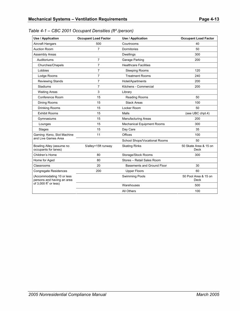
Mechanical Systems – Ventilation Requirements Page 4-13
2005 Nonresidential Compliance Manual March 2005
Table 4-1 – CBC 2001 Occupant Densities (ft² /person)
Use / Application Occupant Load Factor Use / Application Occupant Load Factor Aircraft Hangars 500 Courtrooms 40
Auction Room 7 Dormitories 50
Assembly Areas Dwellings 300
Auditoriums 7 Garage Parking 200
Churches/Chapels 7 Healthcare Facilities
Lobbies 7 Sleeping Rooms 120
Lodge Rooms 7 Treatment Rooms 240
Reviewing Stands 7 Hotel/Apartments 200
Stadiums 7 Kitchens - Commercial 200
Waiting Areas 3 Library
Conference Room 15 Reading Rooms 50
Dining Rooms 15 Stack Areas 100
Drinking Rooms 15 Locker Room 50
Exhibit Rooms 15 Malls (see UBC chpt.4)
Gymnasiums 15 Manufacturing Areas 200
Lounges 15 Mechanical Equipment Rooms 300
Stages 15 Day Care 35
11 Offices 100 Gaming: Keno, Slot Machine and Live Games Area
School Shops/Vocational Rooms 50
Bowling Alley (assume no occupants for lanes)
5/alley+15ft runway Skating Rinks 50 Skate Area & 15 on Deck
Children’s Home 80 Storage/Stock Rooms 300
Home for Aged 80 Stores – Retail Sales Room
Classrooms 20 Basements and Ground Floor 30
Congregate Residences 200 Upper Floors 60
Swimming Pools 50 Pool Area & 15 on Deck
Warehouses 500
(Accommodating 10 or less persons and having an area of 3,000 ft2 or less)
All Others 100

Page 4-14 - Mechanical Systems – Ventilation Requirements
2005 Nonresidential Compliance Manual March 2005
Table 4-2 – Required Minimum Ventilation Rate Per Occupancy
UBC Table No. 10-A Choose Largest
Occupancy / Use ft2/Occupant
Number of People per
1000 ft²
Ventilation CEC STD Table 121-
A cfm/ft²
UBC Based Ventilation
cfm/ft²
Req. Vent cfm/ft² (largest)
1) Aircraft Hangars 500 2 0.15 0.02 0.15
2) Auction Rooms 7.0 143 0.15 1.07 1.07
3) Assembly Areas (Concentrated Use)
Auditoriums 7.0 143 0.15 1.07 1.07
Bowling Alleys 4.0 250 0.15 1.88 1.88
Churches & Chapels (Religious Worship)
7.0 143 0.15 1.07 1.07
Dance Floors 7.0 143 0.15 1.07 1.07
Lobbies 7.0 143 0.15 1.07 1.07
Lodge Rooms 7.0 143 0.15 1.07 1.07
Reviewing Stands 7.0 143 0.15 1.07 1.07
Stadiums 7.0 143 0.15 1.07 1.07
Theaters - All 7.0 143 0.15 1.07 1.07
Waiting Areas 3.0 333 0.15 2.50 2.50
4) Assembly Areas (Nonconcentrated Use)
15.0 67 0.15 0.50 0.50
Conference & Meeting Rooms (1)
15.0 67 0.15 0.50 0.50
Dining Rooms/Areas 15.0 67 0.15 0.50 0.50
Drinking Establishments (2)
15.0 67 0.20 0.50 0.50
Exhibit/Display Areas 15.0 67 0.15 0.50 0.50
Gymnasiums/Sports Arenas
15.0 67 0.15 0.50 0.50
Lounges 15.0 67 0.20 0.50 0.50
Stages 15.0 67 1.50 0.50 1.50
Gaming, Keno, Slot Machine and Live Games Areas
11.0 91 0.20 0.68 0.68
5) Auto Repair Workshops 100.0 10 1.50 0.08 1.50
6) Barber & Beauty Shops 100.0 10 0.40 0.08 0.40
7) Children's Homes & Homes for Aged
80.0 13 0.15 0.09 0.15
8) Classrooms 20.0 50 0.15 0.38 0.38
9) Courtrooms 40.0 25 0.15 0.19 0.19
10) Dormitories 50.0 20 0.15 0.15 0.15
11) Dry Cleaning (Coin-Operated) 100.0 10 0.30 0.08 0.30
12) Dry Cleaning (Commercial) 100.0 10 0.45 0.08 0.45
13) Garage, Parking 200.0 5 0.15 0.04 0.15
14) Healthcare Facilities:
Sleeping Rooms
120.0 8 0.15 0.06 0.15
Treatment Rooms
240.0 4 0.15 0.03 0.15
15) Hotels and Apartments 200.0 5 0.15 0.04 0.15

Mechanical Systems – Ventilation Requirements Page 4-15
2005 Nonresidential Compliance Manual March 2005
UBC Table No. 10-A Choose Largest
Occupancy / Use ft2/Occupant
Number of People per
1000 ft²
Ventilation CEC STD Table 121-
A cfm/ft²
UBC Based Ventilation
cfm/ft²
Req. Vent cfm/ft² (largest)
Hotel Function Area (3) 15.0 67 0.15 0.50 0.50
Hotel Lobby 100.0 10 0.15 0.08 0.15
Hotel Guest Rooms (<500 ft²)
200.0 5 Footnote 4 Footnote 4 Footnote 4
Hotel Guest rooms (>=500 ft²)
200.0 5 0.15 0.04 0.15
Highrise Residential 200.0 5 Footnote 5 Footnote 5 Footnote 5
16) Kitchen(s) 200.0 5 0.15 0.04 0.15
17) Library: Reading Rooms 50.0 20 0.15 0.15 0.15
Stack Areas 100.0 10 0.15 0.08 0.15
18) Locker Rooms 50.0 20 0.15 0.15 0.15
19) Manufacturing 200.0 5 0.15 0.04 0.15
20) Mechanical Equipment Room 300.0 3 0.15 0.03 0.15
21) Nurseries for Children - Day Care
50.0 20 0.15 0.15 0.15
22) Offices:
Office 100.0 10 0.15 0.08 0.15
Bank/Financial Institution
100.0 10 0.15 0.08 0.15
Medical & Clinical Care
100.0 10 0.15 0.08 0.15
23) Retail Stores (See Stores)
24) School Shops & Vocational Rooms
50.0 20 0.15 0.15 0.15
25) Skating Rinks:
Skate Area 50.0 20 0.15 0.15 0.15
On Deck 15.0 67 0.15 0.50 0.50
26) Stores:
Retail Sales, Wholesale Showrooms
30.0 33 0.20 0.25 0.25
Basement and Ground Floor
30.0 33 0.20 0.25 0.25
Upper Floors 60.0 17 0.20 0.13 0.20
Grocery 30.0 33 0.20 0.25 0.25
Malls, Arcades, & Atria 30.0 33 0.20 0.25 0.25
27) Swimming Pools:
Pool Area 50.0 20 0.15 0.15 0.15
On Deck 15.0 67 0.15 0.50 0.50
28) Warehouses, Industrial & Commercial Storage/Stockrooms (see 4.2.1 b) 4.24.2.1D)
500.0 2 0.15 0.02 0.15
29) All Others -- Including Unknown
100.0 10 0.15 0.08 0.15
Corridors, Restrooms, & Support Areas
100.0 10 0.15 0.08 0.15

Page 4-16 - Mechanical Systems – Ventilation Requirements
2005 Nonresidential Compliance Manual March 2005
UBC Table No. 10-A Choose Largest
Occupancy / Use ft2/Occupant
Number of People per
1000 ft²
Ventilation CEC STD Table 121-
A cfm/ft²
UBC Based Ventilation
cfm/ft²
Req. Vent cfm/ft² (largest)
Commercial & Industrial Work
100.0 10 0.15 0.08 0.15
Footnotes: Equations used to find:
1) Convention, Conference, Meeting Rooms
2) Bars, Cocktail & Smoking Lounges, Casinos
1) Number of People per 1000sf = tSf/Occupan1000
3) See Conference Rooms or Dining Rooms 4) Guestrooms less than 500 ft² use 30 cfm/guestroom 5) Highrise Residential See 1994 UBC Section 1203 Ventilation
2) UBC Based Ventilation cfm/ft² = 152
1000 1000sfper People ofNumber
×
cfm
Example 4-9
Question
Ventilation for a two-room building:
Consider a building with two spaces, each having an area of 1,000 ft2. One space is used for general administrative functions, and the other is used for classroom training. It is estimated that the office will contain seven people, and the classroom will contain 50 (fixed seating). What are the required outdoor ventilation rates?
Answer
1. For the office area, the design outdoor ventilation air is the larger of:
7 people x 15 cfm/person = 105 cfm
or
1,000 ft² x 0.15 cfm/ft² = 150 cfm
For this space, the design ventilation rate is 150 cfm.
2. For the classroom, the design outdoor ventilation air is the larger of:
50 people x 15 cfm/person = 750 cfm
or
1,000 ft² x 0.15 cfm/ft² = 150 cfm
For this space the design ventilation rate is 750 cfm.
Assume the total supply air necessary to satisfy cooling loads is 1000 cfm for the office and 1,500 cfm for the classroom. If each space is served by a separate system, then the required outdoor ventilation rate of each system is 150 cfm and 750 cfm, respectively. This corresponds to a 15% outside air (OA) fraction in the office HVAC unit, and 50% in the classroom unit.

Mechanical Systems – Ventilation Requirements Page 4-17
2005 Nonresidential Compliance Manual March 2005
If both spaces are served by a central system, then the total supply will be (1,000 + 1,500) cfm = 2500 cfm. The required outdoor ventilation rate is (150 + 750) = 900 cfm total. The actual outdoor air ventilation rate for each space is:
Office OA = 900 cfm x (1,000 cfm / 2,500 cfm) = 360 cfm
Classroom OA = 900 cfm x (1,500 cfm / 2,500 cfm) = 540 cfm
While this simplistic analysis suggests that the actual OA cfm to the classroom is less than design (540 cfm vs. 750 cfm), the analysis does not take credit for the dilution effect of the air recirculated from the office. The office is over-ventilated (360 cfm vs. 150 cfm) so the concentration of pollutants in the office return air is low enough that it can be used, along with the 540 cfm of outdoor air, to dilute pollutants in the classroom. The Standards allow this design provided that the system always delivers at least 750 cfm to the classroom (including transfer or recirculated air), and that any transfer air is free of unusual contaminants.
4.3.3 Direct Air Transfer
The Standards allow air to be directly transferred from other spaces in order to meet a part of the ventilation supply to a space, provided the total outdoor quantity required by all spaces served by the building’s ventilation system is supplied by the mechanical systems. This method can be used for any space, but is particularly applicable to conference rooms, toilet rooms, and other rooms that have high ventilation requirements. Transfer air must be free from any unusual contaminants, and as such should not be taken directly from rooms where such sources of contaminants are anticipated. It is typically taken from the return plenum or directly from an adjacent space.
Air may be transferred using any method that ensures a positive airflow. Examples include dedicated transfer fans, exhaust fans and fan-powered VAV boxes. A system having a ducted return may be balanced so that air naturally transfers into the space. Exhaust fans serving the space may discharge directly outdoors, or into a return plenum. Transfer systems should be designed to minimize recirculation of transfer air back into the space; duct work should be arranged to separate the transfer air intake and return points.
When each space in a two-space building is served by a separate constant volume system, the calculation and application of ventilation rate is straightforward, and each space will always receive its design outdoor air quantity. However, a central system serving both spaces does not deliver the design outdoor air quantity to each space. Instead, one space receives more than its allotted share, and the other less. This is because the training room has a higher design outdoor ventilation rate and/or a lower cooling load relative to the other space.
4.3.4 Distribution of Outdoor Air to Zonal Units §121(d)
When a return plenum is used to distribute outside air to a zonal heating or cooling unit, the outside air supply must be connected either:

Page 4-18 - Mechanical Systems – Ventilation Requirements
2005 Nonresidential Compliance Manual March 2005
1. Within five ft. of the unit; or
2. Within 15 ft. of the unit, with the air directed substantially toward the unit, and with a discharge velocity of at least 500 ft. per minute.
Water source heat pumps and fan coils are the most common application of this configuration. The unit fans should be controlled to run continuously during occupancy in order for the ventilation air to be circulated to the occupied space.
A central space-conditioning system(s) augmented by a few zonal units for spot conditioning may use transfer air from spaces served by the central system. A direct source of outdoor air is not required for each zonal unit. Similarly, transfer air may be used in buildings having central interior space-conditioning systems with outdoor air, and zonal units on the perimeter (without outdoor air).
While not required, the Standards recommend that sources of unusual contaminants be controlled through the use of containment systems that capture the contaminants and discharge them directly outdoors. Such systems may include exhaust hoods, fume hoods, small space exhausts and differential pressure control between spaces. The designer is advised to consult ASHRAE standards or other publications for guidance in this subject.
4.3.5 Ventilation System Operation and Controls §121(c) & §121(f)
Outdoor Ventilation Air and VAV Systems Except for systems employing Energy Commission-certified demand controlled ventilation (DCV) devices, the Standards require that the minimum rate of outdoor air calculated per §121(b)2 be provided to each space at all times when the space is normally occupied [§121(c)1]. For spaces served by variable air volume (VAV) systems, this means that the minimum supply setting of each VAV box should be no less than the design outdoor ventilation rate calculated for the space, unless transfer air is used. If transfer air is used, the minimum box position, plus the transfer air, must meet the minimum ventilation rate. If transfer air is not used, the box must be controlled so that the minimum required airflow is maintained at all times (unless demand controlled ventilation is employed).
The design outdoor ventilation rate at the system level must always be maintained when the space is occupied, even when the fan has modulated to its minimum capacity [§121(c)1]. Section 4.3.12 describes mandated acceptance test requirements for outside air ventilation in VAV air handling systems. In these tests, the minimum outside air in VAV systems will be measured both at full flow and with all boxes at minimum position.
Figure 4-2 shows a typical VAV system. In standard practice, the testing and balancing (TAB) contractor sets the minimum position setting for the outdoor air damper during construction. It is set under the conditions of design airflow for the system, and remains in the same position throughout the full range of system operation. Does this meet code? The answer is no. As the system airflow drops so will the pressure in the mixed air plenum. A fixed position on the minimum outdoor air damper will produce a varying outdoor airflow. As depicted

Mechanical Systems – Ventilation Requirements Page 4-19
2005 Nonresidential Compliance Manual March 2005
in Figure 4-2, this effect will be approximately linear (in other words outdoor air airflow will drop directly in proportion to the supply airflow).
The following paragraphs present several methods used to dynamically control the minimum outdoor air in VAV systems, which are described in detail below.
Regardless of how the minimum ventilation is controlled, care should be taken to reduce the amount of outdoor air provided when the system is operating during the weekend or after hours with only a fraction of the zones active. §122(g) requires provision of “isolation zones” of 25,000 ft2 or less. This can be provided by having the VAV boxes return to fully closed when their associated zone is in unoccupied mode. When a space or group of spaces is returned to occupied mode (e.g. through off-hour scheduling or a janitor’s override) only the boxes serving those zones need to be active. During this partial occupancy the ventilation air can be reduced to the requirements of those zones that are active. If all zones are of the same occupancy type (e.g. private offices), simply assign a floor area to each isolation zone and prorate the minimum ventilation area by the ratio of the sum of the floor areas presently active divided by the sum of all the floor areas served by the HVAC system.
Figure 4-2 – VAV Reheat System with a Fixed Minimum outdoor Air Damper Setpoint
Fixed Minimum Damper Setpoint This method does not comply with Title 24; the airflow at a fixed minimum damper position will vary with the pressure in the mixed air plenum (see Figure 1-2).
Dual Minimum Setpoint Design This method complies with Title 24 requirements. An inexpensive enhancement to the fixed damper setpoint design is the dual minimum setpoint design, commonly used on some packaged AC units. The minimum damper position is

Page 4-20 - Mechanical Systems – Ventilation Requirements
2005 Nonresidential Compliance Manual March 2005
set proportionally based on fan speed or airflow between a setpoint determined when the fan is at full speed (or airflow) and minimum speed (or airflow). This method complies with the letter of Title 24 but is not accurate over the entire range of airflow rates and when there are wind or stack effect pressure fluctuations. But with DDC, this design has very low costs.
Energy Balance Method This method complies with Title 24 requirements; however, compliance may be difficult for reasons discussed below. The energy balance method (Figure 4-3) uses temperature sensors in the outside, as well as return and mixed air plenums to determine the percentage of outdoor air in the supply air stream. The outdoor airflow is then calculated using the equations shown in Figure 4-3. This method requires an airflow monitoring station on the supply fan.
This approach does not generally work for several reasons:
• The accuracy of the mixed air temperature sensor is critical to the calculation but is very difficult to perform with any precision in real applications. Even with an averaging type bulb, most mixing plenums have some stratification or horizontal separation between the outside and mixed airstreams.7
• Even with the best installation, high accuracy sensors, and field calibration of the sensors, the equation for percent outdoor air will become inaccurate as the return air temperature approaches the outdoor air temperature. When they are equal, this equation predicts an infinite percentage outdoor air.
• The accuracy of the airflow monitoring station at low supply airflows is likely to be low.
• The denominator of the calculation amplifies sensor inaccuracy as the return air temperature approaches the outdoor air temperature.
7 This was the subject of ASHRAE Research Project 1045-RP, “Verifying Mixed Air
Damper Temperature and Air Mixing Characteristics.” Unless the return is over the outdoor air there are significant problems with stratification or airstream separation in mixing plenums.
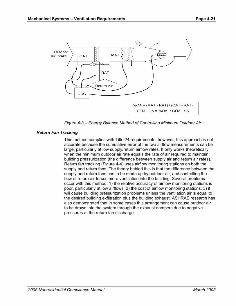
Mechanical Systems – Ventilation Requirements Page 4-21
2005 Nonresidential Compliance Manual March 2005
Figure 4-3 – Energy Balance Method of Controlling Minimum Outdoor Air
Return Fan Tracking This method complies with Title 24 requirements; however, this approach is not accurate because the cumulative error of the two airflow measurements can be large, particularly at low supply/return airflow rates. It only works theoretically when the minimum outdoor air rate equals the rate of air required to maintain building pressurization (the difference between supply air and return air rates). Return fan tracking (Figure 4-4) uses airflow monitoring stations on both the supply and return fans. The theory behind this is that the difference between the supply and return fans has to be made up by outdoor air, and controlling the flow of return air forces more ventilation into the building. Several problems occur with this method: 1) the relative accuracy of airflow monitoring stations is poor, particularly at low airflows; 2) the cost of airflow monitoring stations; 3) it will cause building pressurization problems unless the ventilation air is equal to the desired building exfiltration plus the building exhaust. ASHRAE research has also demonstrated that in some cases this arrangement can cause outdoor air to be drawn into the system through the exhaust dampers due to negative pressures at the return fan discharge.
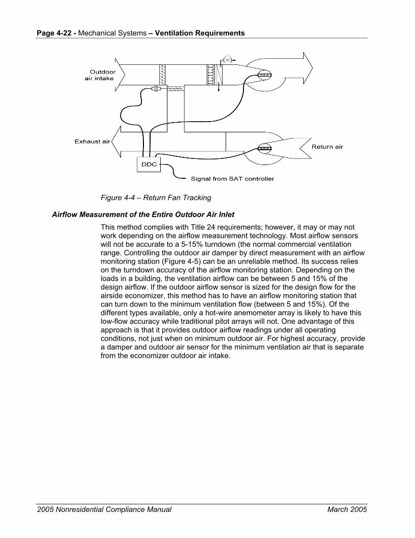
Page 4-22 - Mechanical Systems – Ventilation Requirements
2005 Nonresidential Compliance Manual March 2005
Figure 4-4 – Return Fan Tracking
Airflow Measurement of the Entire Outdoor Air Inlet This method complies with Title 24 requirements; however, it may or may not work depending on the airflow measurement technology. Most airflow sensors will not be accurate to a 5-15% turndown (the normal commercial ventilation range. Controlling the outdoor air damper by direct measurement with an airflow monitoring station (Figure 4-5) can be an unreliable method. Its success relies on the turndown accuracy of the airflow monitoring station. Depending on the loads in a building, the ventilation airflow can be between 5 and 15% of the design airflow. If the outdoor airflow sensor is sized for the design flow for the airside economizer, this method has to have an airflow monitoring station that can turn down to the minimum ventilation flow (between 5 and 15%). Of the different types available, only a hot-wire anemometer array is likely to have this low-flow accuracy while traditional pitot arrays will not. One advantage of this approach is that it provides outdoor airflow readings under all operating conditions, not just when on minimum outdoor air. For highest accuracy, provide a damper and outdoor air sensor for the minimum ventilation air that is separate from the economizer outdoor air intake.
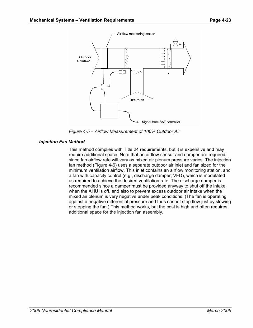
Mechanical Systems – Ventilation Requirements Page 4-23
2005 Nonresidential Compliance Manual March 2005
Figure 4-5 – Airflow Measurement of 100% Outdoor Air
Injection Fan Method This method complies with Title 24 requirements, but it is expensive and may require additional space. Note that an airflow sensor and damper are required since fan airflow rate will vary as mixed air plenum pressure varies. The injection fan method (Figure 4-6) uses a separate outdoor air inlet and fan sized for the minimum ventilation airflow. This inlet contains an airflow monitoring station, and a fan with capacity control (e.g., discharge damper; VFD), which is modulated as required to achieve the desired ventilation rate. The discharge damper is recommended since a damper must be provided anyway to shut off the intake when the AHU is off, and also to prevent excess outdoor air intake when the mixed air plenum is very negative under peak conditions. (The fan is operating against a negative differential pressure and thus cannot stop flow just by slowing or stopping the fan.) This method works, but the cost is high and often requires additional space for the injection fan assembly.

Page 4-24 - Mechanical Systems – Ventilation Requirements
2005 Nonresidential Compliance Manual March 2005
Figure 4-6 – Injection Fan with Dedicated Minimum Outdoor Air Damper
Dedicated Minimum Ventilation Damper with Pressure Control This approach is low cost and takes little space. It can be accurate if the differential setpoint corresponding to the minimum outdoor air rate is properly set in the field. An inexpensive but effective design uses a minimum ventilation damper with differential pressure control (Figure 4-7). In this method, the economizer damper is broken into two pieces: a small two position damper controlled for minimum ventilation air and a larger, modulating, maximum outdoor air damper that is used in economizer mode. A differential pressure transducer is placed across the minimum outdoor air damper. During start-up, the air balancer opens the minimum outside air (OA) damper and return air damper, closes the economizer OA damper, runs the supply fan at design airflow, measures the OA airflow (using a hand-held velometer) and adjusts the minimum OA damper position until the OA airflow equals the design minimum OA airflow. The linkages on the minimum OA damper are then adjusted so that the current position is the “full open” actuator position. At this point the design pressure (DP) across the minimum OA damper is measured. This value becomes the DP setpoint. The principle used here is that airflow is constant across a fixed orifice (the open damper) at fixed DP.
As the supply fan modulates when the economizer is off, the return air damper is controlled to maintain the DP setpoint across the minimum ventilation damper.
The main downside to this method is the complexity of controls and the potential problems determining the DP setpoint in the field. It is often difficult to measure the outdoor air rate due to turbulence and space constraints.

Mechanical Systems – Ventilation Requirements Page 4-25
2005 Nonresidential Compliance Manual March 2005
Figure 4-7 – Minimum Outdoor Air Damper with Pressure Control
Example 4-10
Question
Minimum VAV cfm:
If the minimum required ventilation rate for a space is 150 cfm, what is the minimum allowed airflow for its VAV box when the design percentage of outdoor air in the supply is 20%?
Answer
The minimum allowed airflow may be as low as 150 cfm provided that enough outdoor air is supplied to all spaces combined to meet the requirements of §121(b)2 for each space individually.
4.3.6 Pre-Occupancy Purge §121(c)2
Since many indoor air pollutants are out gassed from the building materials and furnishings, the Standards require that buildings having a scheduled operation be purged before occupancy [§121(c)2]. Immediately prior to occupancy, outdoor ventilation must be provided in an amount equal to the lesser of:
• The minimum required ventilation rate for one hour; or
• Three complete air changes.
Either criteria can be used to comply with the Standards. Three complete air changes means an amount of ventilation air equal to three times the volume of the occupied space. This air may be introduced at any rate provided for and allowed by the system, so that the actual purge period may be less than an hour.
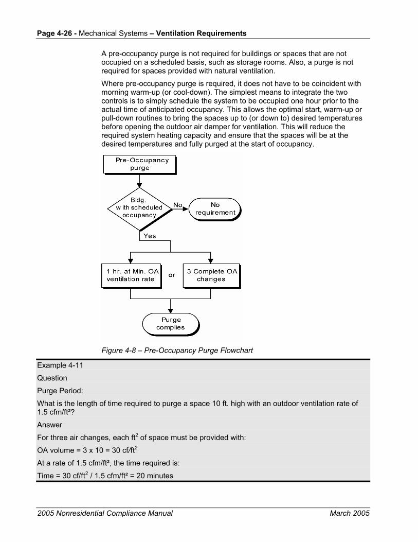
Page 4-26 - Mechanical Systems – Ventilation Requirements
2005 Nonresidential Compliance Manual March 2005
A pre-occupancy purge is not required for buildings or spaces that are not occupied on a scheduled basis, such as storage rooms. Also, a purge is not required for spaces provided with natural ventilation.
Where pre-occupancy purge is required, it does not have to be coincident with morning warm-up (or cool-down). The simplest means to integrate the two controls is to simply schedule the system to be occupied one hour prior to the actual time of anticipated occupancy. This allows the optimal start, warm-up or pull-down routines to bring the spaces up to (or down to) desired temperatures before opening the outdoor air damper for ventilation. This will reduce the required system heating capacity and ensure that the spaces will be at the desired temperatures and fully purged at the start of occupancy.
Figure 4-8 – Pre-Occupancy Purge Flowchart
Example 4-11
Question
Purge Period: What is the length of time required to purge a space 10 ft. high with an outdoor ventilation rate of 1.5 cfm/ft²?
Answer
For three air changes, each ft2 of space must be provided with:
OA volume = 3 x 10 = 30 cf/ft2
At a rate of 1.5 cfm/ft², the time required is:
Time = 30 cf/ft2 / 1.5 cfm/ft² = 20 minutes

Mechanical Systems – Ventilation Requirements Page 4-27
2005 Nonresidential Compliance Manual March 2005
Example 4-12
Question
Purge with Natural Ventilation:
In a building with natural ventilation, do the windows need to be left open all night to accomplish a building purge?
Answer
No. A building purge is required only for buildings with mechanical ventilation systems.
Example 4-13
Question
Purge with Occupancy Timer:
How is a purge accomplished in a building without a regularly scheduled occupancy whose system operation is controlled by an occupancy sensor?
Answer
There is no purge requirement for this building. Note that occupancy sensors and manual timers can only be used to control ventilation systems in buildings that are intermittently occupied without a predictable schedule.
4.3.7 Demand Controlled Ventilation §121(c)
Demand controlled ventilation (DCV) systems reduce the amount of ventilation supply air in response to a measured level of carbon dioxide (CO2) in the breathing zone. The Standards only permit CO2 sensors for the purpose of meeting this requirement; VOC and so-called “IAQ” sensors are not approved as alternative devices to meet this requirement. The Standards only permit DCV systems to vary the ventilation component that corresponds to occupant bioeffluents (this is basis for the 15 cfm/person portion of the ventilation requirement). Since only CO2 sensors directly track occupancy they are the only sensors permitted.
The Standards requires the use of DVC systems for spaces with all of the following characteristics:
• Served by single zone units.
• Have a design occupancy of 40 ft2/person or smaller (for areas without fixed seating where the design density for egress purposes in the CBC is 40 ft2/person or smaller).
• Has an outdoor air economizer.
There are three exceptions to this requirement:
1. Classrooms (they are permitted to use DCV but not required to)
2. Where the space exhaust is greater than the Standards Table 121(b) value minus 0.2 cfm/ft2.
Page 4-28 - Mechanical Systems – Ventilation Requirements
2005 Nonresidential Compliance Manual March 2005
3. Spaces that have processes or operations that generate dusts, fumes, mists, vapors, or gases and are not provided with local exhaust ventilation (such as indoor operation of internal combustion engines or areas designated for unvented food service preparation).
Classrooms were exempted due to concerns about equipment maintenance in school buildings. The second exception relates to the fact that spaces with high exhaust requirements won’t have any room to turn down (therefore there will be minimal savings from the DCV controls). The third exception recognizes that some spaces may need additional ventilation due to contaminants that are not occupant borne. It addresses spaces like theater stages where theatrical fog may be used or movie theater lobbies where unvented popcorn machines may be emitting odors and vapors into the space in either case justifying the need for higher ventilation rates.
Although not required, the Standards permit design professionals to apply DCV on any intermittently occupied spaces served by either single-zone or multiple-zone equipment.
CO2 based DCV is based on two principles:
1. Several studies (Berg-Munch et al. 1986, Cain et al. 1983, Fanger 1983 and 1988, Iwashita et al. 1990, Rasmussen et al. 1985) concluded that about 15 cfm of outdoor air ventilation per person will control human body odor such that roughly 80% of unadapted persons (visitors) will find the odor to be at an acceptable level. These studies are the basis of the 15 cfm/person rate required by these Standards and most building codes. This ventilation rate can be roughly equated to CO2 concentration using the following steady-state equation.
( )V NC Cin ss out
=−
&
,
where V is the ventilation rate per person, &N is the CO2 generation rate per person, Cin,ss is the steady-state value of the indoor CO2 concentration, and Cout is the outdoor concentration. At the rate of CO2 generated by adults at typical activity levels in offices, 15 cfm/person equates to a differential CO2 concentration (indoor minus outdoor) of approximately 700 ppm.
2. The same level of odor acceptability was found to occur at 700 ppm differential CO2 concentration even for spaces that were not at equilibrium (Berg-Munch et al. 1986, Fanger 1983, Rasmussen et al. 1985), and the correlation was not strongly dependent on the level of physical activity. This suggests that while CO2 concentration may not track the number of occupants when spaces are not at steady-state, it does track the concentration of bioeffluents that determine people’s perception of air quality. It also suggests that odorous bioeffluents are generated at approximately the same rate as CO2. Hence as activity level and bioeffluent generation rate increases ( &N in the equation above), the rate of outdoor air required to provide acceptable air quality (V) increases proportionally, resulting in the same differential CO2 concentration.
Note that CO2 concentration only tracks indoor contaminants that are generated by occupants themselves and, to a lesser extent, their activities. It will not track other pollutants, particularly volatile organic compounds (VOCs) that off-gas
Mechanical Systems – Ventilation Requirements Page 4-29
2005 Nonresidential Compliance Manual March 2005
from furnishings and building materials. Hence, where permitted or required by the Standards, demand controlled ventilation systems cannot reduce the outdoor air ventilation rate below the floor rate listed in Standards Table 121-A (typically 0.15 cfm/ft2) during normally occupied times.
DCV systems save energy if the occupancy varies significantly over time. Hence they are most cost effective when applied to densely occupied spaces like auditoriums, conference rooms, lounges or theaters. Because DCV systems must maintain the floor ventilation rate listed in Standards Table 121-A, they will not be applicable to sparsely occupied buildings such as offices where the floor rate always exceeds the minimum rate required by the occupants (see Table 4-2).
Where DCV is employed (whether mandated or not) the controls must meet all of the following requirements:
• Sensors must be provided in each room served by the system that has a design occupancy of 40 ft2/person or less.
• The CO2 sensors must be located in the breathing zone (between 1 and 6 ft. above the floor). Sensors in return air ducts are not allowed since they can result in under-ventilation due to CO2 measurement error caused by short-circuiting of supply air into return grilles and leakage of outdoor air (or return air from other spaces) into return air ducts.
• The ventilation must be maintained that will result in a concentration of CO2 at or below 600 ppm above the ambient level. The ambient levels can either be assumed to be 400 ppm or dynamically measured. At 400 ppm outside CO2 concentration, the resulting DCV CO2 setpoint would be 1000 ppm. (Note that a 600 ppm differential is less than the 700 ppm that corresponds to the 15 cfm/person ventilation rate. This provides a margin of safety against sensor error, and because 1000 ppm CO2 is a commonly recognized guideline value and referenced in earlier versions of ASHRAE Standard 62.)
• Regardless of the CO2 sensor’s reading, the system is not required to provide more than the minimum ventilation rate required by §121(b). This high limit can be implemented in the controls.
• The system shall always provide a minimum ventilation of the sum of the Standards Table 121-A values for all rooms with DCV and §121(b)2 (Table 4-2 of this manual) for all other spaces served by the system. This is a low limit setting that must be implemented in the controls.
• The CO2 sensors must be factory certified to have an accuracy of no less than 75 ppm over a five-year period without recalibration in the field. A number of manufacturers have “self calibrating” sensors now that adjust to ambient levels during unoccupied times. The manufacturers of sensors must provide a document to installers that their sensors meet these requirements. The installer must make this certification information available to the builder, building inspectors and, if specific sensors are specified on the plans, to plan checkers.
Page 4-30 - Mechanical Systems – Ventilation Requirements
2005 Nonresidential Compliance Manual March 2005
Section 4.3.12 describes mandated acceptance test requirements for DCV systems.
Example 4-14
Question
Does a single zone air-handling unit serving a 2,000 ft² auditorium with fixed seating for 240 people require demand controlled ventilation?
Answer
Yes if it has an air-side economizer. There are three tests for the requirement.
The first test is whether the design occupancy is 40 ft2/person or less. This space has 2,000 ft²/240 people or 8.3 ft² /person.
The second test is that the unit is single zone
The third is that it has an air-side economizer.
A single CO2 sensor could be used for this space provided it is certified by the manufacturer to cover 2,000 ft² of space. The sensor must be placed directly in the space.
Example 4-15
Question
If two separate units are used to condition the auditorium in the previous example, is demand controlled ventilation required?
Answer
Yes, if they each meet the three tests.
4.3.8 Fan Cycling
While §121(c)1 requires that ventilation be continuous during normally occupied hours, Exception No. 2 allows the ventilation to be disrupted for not more than five minutes out of every hour. In this case the ventilation rate during the time the system is ventilating must be increased so the average rate over the hour is equal to the required rate.
This restriction limits the duty cycling of fans by energy management systems to not more than five minutes out of every sixty minutes. In addition, when a space-conditioning system that also provides ventilation is controlled by a thermostat incorporating a fan “On/Auto” switch, the switch should be set to the “On” position. Otherwise, during mild conditions, the fan may be off the majority of the time.
4.3.9 Variable Air Volume (VAV) Changeover Systems
Some VAV systems provide conditioned supply air, either heated or cooled, through a single set of ducting. These systems are called VAV changeover systems or, perhaps more commonly, variable volume and temperature (VVT™) systems, named after a control system distributed by Carrier Corp. In the event that heating is needed in some spaces at the same time that cooling is needed

Mechanical Systems – Ventilation Requirements Page 4-31
2005 Nonresidential Compliance Manual March 2005
in others, the system must alternate between supplying heated and cooled air. When the supply air is heated, for example, the spaces requiring cooling are isolated (cut off) by the VAV dampers and must wait until the system switches back to cooling mode. In the meantime, they are generally not supplied with ventilation air.
Systems of this type may not meet the ventilation requirements if improperly applied. Where changeover systems span multiple orientations the designer must make control provisions to ensure that no zone is shut off for more than five minutes per hour and that ventilation rates are increased during the remaining time to compensate. Alternatively, minimum damper position or airflow setpoints can be set for each zone to maintain supply air rates, but this can result in temperature control problems since warm air will be supplied to spaces that require cooling, and vice versa. Changeover systems that are applied to a common building orientation (e.g., all east or all interior) are generally the most successful since zones will usually have similar loads, allowing minimum airflow rates to be maintained without causing temperature control problems.
4.3.10 Adjustment of Ventilation Rate
Section 121(b) specifies the minimum required outdoor ventilation rate, but does not restrict the maximum. However, if the designer elects to have the space-conditioning system operate at a ventilation rate higher than the rate required by the Standards, then the Standards require that the space-conditioning system must be adjustable so that in the future the ventilation rate can be reduced to the amount required by the Standards or the rate required for make-up of exhaust systems that are required for a process, for control of odors, or for the removal of contaminants within the space [§121(e)].
In other words, a system can be designed to supply higher than minimum outside air volumes provided dampers or fan speed can be adjusted to allow no more than the minimum volume if, at a later time, someone decides it is desirable. The Standards preclude a system designed for 100% outdoor air, with no provision for any return air, unless the supply air quantity can be adjusted to be equal to the designed minimum outdoor air volume. The intent is to prevent systems from being designed that will permanently over-ventilate spaces.
4.3.11 Miscellaneous Dampers §122(f)
Dampers should not be installed on combustion air intakes, or where prohibited by other provisions of law [§122(f) Exception Nos. 3 & 4]. If the designer elects to install dampers on shaft vents to help control stack-induced infiltration, the damper should be motorized and controlled to open in accordance with applicable fire codes.

Page 4-32 - Mechanical Systems – Ventilation Requirements
2005 Nonresidential Compliance Manual March 2005
4.3.12 Acceptance Requirements §121(f), 122(h) and 121(c)5
The Standards have acceptance test requirements for:
• Ventilation quantities at design airflow [§121(f)].
• Ventilation quantities at minimum airflow [VAV systems, §121(f)].
• Ventilation system time controls [§122(h)].
• Demand controlled ventilation systems [§121(c)5].
These test requirements are described in Chapter 8 and in the Non-Residential ACM Manual Appendix NJ. They are described in brief in the following paragraphs.
Example 4-16
Question
Maintenance of Ventilation System:
In addition to these commissioning requirements for the ventilation system, are there any periodic requirements for inspection?
Answer
The Standards do not contain any such requirements since they apply to the design and commissioning of buildings, not to its later operation. However, Section 5142 of the General Industry Safety Orders, Title 8, California Safety Code (1987): Mechanically Driven Heating, Ventilating and Air Conditioning (HVAC) Systems to Provide Minimum Building Ventilation, states the following:
(b) Operation and Maintenance
(1) The HVAC system shall be inspected at least annually, and problems found during these inspections shall be corrected within a reasonable time.
(2) Inspections and maintenance of the HVAC systems shall be documented in writing. The employer shall record the name of the individual(s) inspecting and/or maintaining the system, the date of the inspection and/or maintenance, and the specific findings and actions taken. The employer shall ensure that such records are retained for at least five years.
(3) The employer shall make all records required by this section available for examination and copying, within 48 hours of a request, to any authorized representative of the Division (as defined in Section 3207 of Title 8), to any employee of the employer affected by this section, and to any designated representative of said employee of the employer affected by this Section.
Ventilation Airflow §121(f)
Ventilation airflow has to be certified as within 10% of the design airflow quantities at two points of operation: full design supply airflow and (for VAV systems) at airflow with all VAV boxes at minimum position.

Mechanical Systems – Pipe and Duct Distribution Systems Page 4-33
2005 Nonresidential Compliance Manual March 2005
If airflow monitoring stations are provided, they can be used for these measurements.
Ventilation System Time Controls and Preoccupancy Purge 122(h)
Programming for preoccupancy purge and HVAC schedules are checked and certified as part of the acceptance requirements. The sequences are also required to be identified by specification section paragraph number (or drawing sheet number) in the compliance forms.
Demand Controlled Ventilation System 121(c)5
Demand controlled ventilation systems are checked for compliance with sensor location, calibration (either factory certificate or field validation) and tested for system response with both a high signal (from test gas or breathing on the sensor) and low signal (by increasing the setpoint above the ambient level). A certificate of acceptance must be provided to the building department that the demand control ventilation system meets the Acceptance Requirements for Code Compliance. The certificate of acceptance must include certification from the manufacturers of sensor devices that they will meet the requirements of §121(c)4F and that they will provide a signal that indicates the CO2 level in the range required by §121(c)4, certification from the controls manufacturer that they respond to the type of signal that the installed sensors supply and that they can be calibrated to the CO2 levels specified in §121(c)4, and that the CO2 sensors have an accuracy of no lies than 75 ppm and require calibration no more frequently than once every five years.
4.4 Pipe and Duct Distribution Systems
4.4.1 Mandatory Measures
Requirements for Pipe Insulation §123 Table 123-A
Most piping conveying either mechanically heated or chilled fluids for space conditioning or service water heating must be insulated in accordance with §123. The required thickness of piping insulation depends on the temperature of the fluid passing through the pipe, the pipe diameter, the function of the pipe within the system, and the insulation’s thermal conductivity.
Standards Table 123-A specifies the requirements in terms of inches of insulation with a conductivity within a specific range. These conductivities are typical for fiberglass or foam pipe insulation. In this table, runouts are defined as being less than two inches in diameter, less than 12 feet long, and connected to fixtures or individual terminal units. Piping within fan coil units and within other

Page 4-34 - Mechanical Systems – Pipe and Duct Distribution Systems
2005 Nonresidential Compliance Manual March 2005
heating or cooling equipment may be considered runouts for the purposes of determining the required pipe insulation.
Piping that does not require insulation includes the following:
• Factory installed piping within space-conditioning equipment certified under §111 or §112. Nationally recognized certification programs that are accepted by the Commission for certifying efficiencies of appliances and equipment are considered to meet the requirements for this exception.
• Piping that conveys fluid with a design operating temperature range between 60°F and 105°F, such as cooling tower piping or piping in water loop heat pump systems.
• Piping that serves process loads, gas piping, cold domestic water piping, condensate drains, roof drains, vents or waste piping.
Note: Designers may specify exempt piping conveying cold fluids to be insulated in order to control condensation on the surface of the pipe. Examples may include cold domestic water piping, condensate drains and roof drains. In these cases, the insulation R-value is specified by the designer and is not subject to these regulations.
• Where the heat gain or heat loss, to or from piping without insulation, will not increase building source energy use. For example, piping connecting fin-tube radiators within the same space would be exempt, as would liquid piping in a split system air conditioning unit.
This exception would not exempt piping in solar systems. Solar systems typically have backup devices that will operate more frequently if piping losses are not minimized.
• Piping that penetrates framing members shall not be required to have pipe insulation for the distance of the framing penetration. Metal piping that penetrates metal framing shall use grommets, plugs, wrapping or other insulating material to assure that no contact is made with the metal framing.
Conductivities and thicknesses listed in Standards Table 123-A are typical for fiberglass and foam. When insulating materials are used that have conductivities different from those listed here for the applicable fluid range, such as calcium silicate, Standards Equation 123-A may be used to calculate the required insulation thickness.
When a pipe carries cold fluids, condensation of water vapor within the insulation material may impair the effectiveness of the insulation, particularly for applications in very humid environments or for fluid temperatures below 40°F. Examples include refrigerant suction piping and low-temperature thermal energy storage (TES) systems. In these cases, manufacturers should be consulted and consideration given to low permeability vapor barriers, or closed-cell foams.

Mechanical Systems – Pipe and Duct Distribution Systems Page 4-35
2005 Nonresidential Compliance Manual March 2005
The Standards also require that exposed pipe insulation be protected from damage by moisture, UV and physical abrasion including but not limited to the following:
• Insulation exposed to weather shall be suitable for outdoor service; e.g., protected by aluminum, sheet metal, painted canvas, or plastic cover. Cellular foam insulation shall be protected as above or painted with a coating that is water retardant and provides shielding from solar radiation that can cause degradation of the material.
• Insulation covering chilled water piping and refrigerant suction piping located outside the conditioned space shall include a vapor retardant located outside the insulation (unless the insulation is inherently vapor retardant), all penetrations and joints of which shall be sealed.
If the conductivity of the proposed insulation does not fall into the conductivity range listed in Standards Table 123-A, the minimum thickness must be adjusted using the following equation:
Equation 4-2–Insulation Thickness
T = PR[(1 + t/PR)K/k – 1]
Where:
T Minimum insulation thickness for material with conductivity K, inches.
PR Pipe actual outside radius, inches.
t Insulation thickness, inches (from Standards Table 123-A for conductivity k).
K Conductivity of alternate material at the mean rating temperature indicated in Standards Table 123-A for the applicable fluid temperature range, in Btu-in./(h-ft² -°F).
k The lower value of the conductivity range listed in Standards Table 123-A for the applicable fluid temperature, Btu-in/(h-ft² -°F).

Page 4-36 - Mechanical Systems – Pipe and Duct Distribution Systems
2005 Nonresidential Compliance Manual March 2005
Table 4-3 – Standards Table 123-A Pipe Insulation Thickness
NOMINAL PIPE DIAMETER (in inches)
Runouts up to 2
1 and less
1.25-2 2.50-4 5-6 8 and larger
FLUID TEMPERATURE RANGE, (°F)
CONDUCTIVITYRANGE (in Btu-inch per hour per square foot per °F)
INSULATION MEAN RATING TEMPERATURE (°F)
INSULATION THICKNESS REQUIRED (in inches) Space heating systems (steam, steam condensate and hot water)
Above 350 0.32-0.34 250 1.5 2.5 2.5 3.0 3.5 3.5
251-350 0.29-0.31 200 1.5 2.0 2.5 2.5 3.5 3.5
201-250 0.27-0.30 150 1.0 1.5 1.5 2.0 2.0 3.5
141-200 0.25-0.29 125 0.5 1.5 1.5 1.5 1.5 1.5
105-140 0.24-0.28 100 0.5 1.0 1.0 1.0 1.5 1.5
Service water-heating systems (recirculating sections, all piping in electric trace tape systems, and the first 8 feet of piping from the storage tank for nonrecirculating systems)
Above 105 0.24-0.28 100 0.5 1.0 1.0 1.5 1.5 1.5
Space cooling systems (chilled water, refrigerant and brine)
40-60 0.23-0.27 75 0.5 0.5 0.5 1.0 1.0 1.0
Below 40 0.23-0.27 75 1.0 1.0 1.5 1.5 1.5 1.5
Example 4-17
Question
What is the required thickness for calcium silicate insulation on a 4 inch diameter pipe carrying a 300°F fluid?
Answer
From Table 123-A in the Standards, the required insulation thickness is 2.5 inches for a 4 inch pipe in the range of 251-350°F.
The bottom of the range for mean conductivity at this temperature is listed as 0.29 (Btu-in.)/(h-ft²-°F). From manufacturer’s data, it is determined that the conductivity of calcium silicate at 300°F is 0.45 Btu-in./(h-ft²-°F). The required thickness is therefore:
T = PR[(1 + t/PR)K/k – 1]
T = 4"[(1 + 2.5/4)(0.045/0.29)– 1]
T = 2.83”
When insulation is not available in the exact thickness calculated, the installed thickness should be the next larger available size.
Requirements for Air Distribution System Ducts and Plenums §124
Poorly sealed or poorly insulated duct work can cause substantial losses of air volume and energy. All air distribution system ducts and plenums, including building cavities, mechanical closets, air handler boxes and support platforms used as ducts or plenums, are required to be installed, sealed, and insulated in accordance with the 2001 California Mechanical Code (CMC) Sections 601, 602, 603, 604, 605 and Standard 6-5.

Mechanical Systems – Pipe and Duct Distribution Systems Page 4-37
2005 Nonresidential Compliance Manual March 2005
Installation and Insulation §124(a)
Portions of supply-air and return-air ducts ductwork conveying heated or cooled air located in one or more of the following spaces shall be insulated to a minimum installed level of R-8:
• Outdoors, or
• In a space between the roof and an insulated ceiling, or
• In a space directly under a roof with fixed vents or openings to the outside or unconditioned spaces, or
• In an unconditioned crawlspace; or
• In other unconditioned spaces.
Portions of supply-air ducts ductwork that are not in one of these spaces shall be insulated to a minimum installed level of R-4.2 (or any higher level required by CMC Section 605) or be enclosed in directly conditioned space. CMC insulation requirements are reproduced in Table 4-4. The following are also required:
• Mechanically fasten connections between metal ducts and the inner core of flexible ducts.
• Seal openings with mastic, tape, aerosol sealant or other duct closure system that meets the applicable requirements of UL 181, UL 181A, UL 181B or UL 723 (aerosol sealant).
• When mastic or tape is used to seal openings greater than 1/4 in., a combination of mastic and mesh or mastic and tape must be used.
Factory-Fabricated Duct Systems §124(b)1
Factory-fabricated duct systems must meet the following requirements:
• Duct and closure systems comply with UL 181, including collars, connections and splices, and must be UL labeled.
• Pressure-sensitive tapes, heat-activated tapes, and mastics used in the manufacture of rigid fiberglass ducts comply with UL 181.
• Pressure-sensitive tapes and mastics used with flexible ducts comply with UL 181 or UL 181B.
• Joints and seams of duct systems and their components shall not be sealed with cloth back rubber adhesive duct tapes unless such tape is used in combination with mastic and drawbands.
Field-Fabricated Duct Systems §124(b)2
Field-fabricated duct systems must meet the following requirements:
• Factory-made rigid fiberglass and flexible ducts for field-fabricated duct systems comply with UL 181. Pressure-sensitive tapes, mastics,

Page 4-38 - Mechanical Systems – Pipe and Duct Distribution Systems
2005 Nonresidential Compliance Manual March 2005
aerosol sealants or other closure systems must meet applicable requirements of UL 181, UL 181A or UL 181B.
• Mastic Sealants and Mesh.
• Sealants comply with UL 181, UL 181A, or UL 181B, and must be non-toxic and water resistant.
• Sealants for interior applications pass ASTM Tests C 731(extrudability after aging) and D 2202 (slump test on vertical surfaces), incorporated herein by reference.
• Sealants for exterior applications shall pass ASTM Tests C 731, C 732 (artificial weathering test) and D 2202, incorporated herein by reference.
• Sealants and meshes shall be rated for exterior use.
• Pressure-sensitive tapes comply with UL 181, UL 181A or UL 181B.
• Drawbands used with flexible duct shall:
• Be either stainless-steel worm-drive hose clamps or uv-resistant nylon duct ties.
• Have a minimum tensile strength rating of 150 pounds.
• Be tightened as recommended by the manufacturer with an adjustable tensioning tool.
• Aerosol-Sealant Closures.
• Aerosol sealants meet applicable requirements of UL 723 and must be applied according to manufacturer specifications.
• Tapes or mastics used in combination with aerosol sealing must meet the requirements of this section.
• Joints and seams of duct systems and their components shall not be sealed with cloth back rubber adhesive duct tapes unless such tape is used in combination with mastic and drawbands.
Duct Insulation R-Values §124(c), 124(d) & 124(e)
Since 2001, the Standards have included the following requirements for the labeling, measurement and rating of duct insulation:
• Insulation R-values shall be based on the insulation only and not include air-films or the R-values of other components of the duct system.
• Insulation R-values shall be tested C-values at 75°F mean temperature at the installed thickness, in accordance with ASTM C 518 or ASTM C 177.
• The installed thickness of duct insulation for purpose of compliance shall be the nominal thickness for duct board, duct liner, factory made flexible air ducts and factory-made rigid ducts. For factory-
Mechanical Systems – Pipe and Duct Distribution Systems Page 4-39
2005 Nonresidential Compliance Manual March 2005
made flexible air ducts, the installed thickness shall be determined by dividing the difference between the actual outside diameter and nominal inside diameter by two.
• The installed thickness of duct insulation for purpose of compliance shall be 75% of its nominal thickness for duct wrap.
• Insulated flexible air ducts must bear labels no further than 3 ft. apart that state the installed R-value (as determined per the requirements of the Standards).
A typical duct wrap, nominal 1-1/2 inch and 0.75 pcf will have an installed rating of R-4.2 with 25% compression.
Protection of Duct Insulation §124(f)
The Standards require that exposed duct insulation be protected from damage by moisture, UV and physical abrasion including but not limited to the following:
• Insulation exposed to weather shall be suitable for outdoor service; e.g., protected by aluminum, sheet metal, painted canvas, or plastic cover.
• Cellular foam insulation shall be protected as above or painted with a coating that is water retardant and provides shielding from solar radiation that can cause degradation of the material.
Example 4-18
Question
What are the sealing requirements in a VAV system having a static pressure setpoint of 1.25” w.g. and a plenum return?
Answer
All duct work located within the return plenum must be sealed in accordance with the California Mechanical Code (CMC) Sections 601, 602, 603, 604 and 605 (refer to §124). Pressure-sensitive tape, heat-seal tape and mastic may be used, if it meets the applicable requirement of UL 181, 181A, 181B, to seal joints and seams which are mechanically fastened per the CMC.

Page 4-40 - Mechanical Systems – Pipe and Duct Distribution Systems
2005 Nonresidential Compliance Manual March 2005
Table 4-4 – Duct Insulation Requirements
INSULATION R-VALUEMECHANICALLY HEATING INSULATION R-VALUE
DUCT LOCATION 1 COOLED ZONE HEATING ONLY On roof on exterior building 6.3 < 4,500 DD 2.1
< 8,000 DD 4.2 Attics, garages, and crawl spaces 2.1 < 4,500 DD 2.1
< 8,000 DD 4.2 In walls 2 and within floor to ceiling spaces 2 2.1 < 4,500 DD 2.1
< 8,000 DD 4.2 Within the conditioned space or in basements; None Required None Required return ducts in air plenums Cement slab or within ground None Required None Required 1
Vapor barriers shall be installed on supply ducts in spaces vented to the outside in geographic areas where the average July, August and September mean dew point temperature exceeds 60 degrees Fahrenheit.
2 Insulation may be omitted on that portion of a duct which is located within a wall or a floor to ceiling space where:
a. Both sides of the space are exposed to conditioned air.
b. The space is not ventilated. c. The space is not used as a return plenum. d. The space is not exposed to unconditioned air. Ceilings which form plenums need not be insulated. NOTE: Where ducts are used for both heating and cooling, the minimum insulation shall be as required for the most restrictive condition.
Source: Uniform Mechanical Code §605
4.4.2 Prescriptive Requirements
Duct Leakage Ducts on small single zone systems with portions of the ductwork either out of doors or in uninsulated or vented ceiling spaces are required to be sealed and leak tested [§144(k) and §125]. This will generally only apply to small commercial projects that are one or two stories with packaged single zone units or split systems. Duct leakage testing only applies when all of the following are true:
• The system is constant volume.
• It serves less than 5000 ft2 of conditioned space.
• 25% or more of the duct surface area is located in the outdoors, unconditioned space, a ventilated attic, in a crawl space or where the U-factor of the roof is greater than the U-factor of the ceiling [except where the roof meets with the requirements of §143(a)1C].
Where duct sealing and leakage testing is required, the ducts must be tested by a HERS certified agency to demonstrate a leakage rate of ≤6% of fan flow.
§149(b)1D requires that duct sealing apply to new ducts on existing systems and existing ducts on existing systems that are being either repaired or replaced. Where an entirely new duct system is being installed, and meets the

Mechanical Systems – Pipe and Duct Distribution Systems Page 4-41
2005 Nonresidential Compliance Manual September 2005
criteria previously described it must meet or exceed the leakage rate of ≤ 6% of fan flow.
If the new ducts are an extension of an existing duct system the combined system (new and existing ducts) must meet:
• A leakage rate of < 15% of fan flow, or
• A reduction in leakage rate of > 60% (as compared to the existing ductwork) with all “accessible” leaks demonstrated through visual inspection to have been sealed, or
• All accessible leaks shall be sealed and verified through a visual inspection by a certified HERS rater.
There is an exception for ducts that are connected to existing ducts with asbestos insulation or sealant.
These requirements also apply to cases where existing HVAC equipment is either repaired or replaced. With exceptions for ducts that are insulated or sealed with asbestos and an existing duct system that has previously been leakage tested by a certified California HERS rater (see http://www.energy.ca.gov/HERS/).
One can avoid sealing the ducts by insulating the roof and sealing the attic vents as part of a larger remodel, thereby creating a conditioned space within which the ducts are located, and no longer meets the criteria of §144 k.
Another alternative to duct sealing is to install a high efficiency air conditioner that will save as much energy as the duct system is losing though leaks. This trade-off can be calculated using the performance software or by using pre-calculated equipment efficiencies deemed comparable to duct sealing. In climate zones 1-15, systems with air conditioner efficiencies at least as high as those in Table 4-5 are deemed equivalent to duct sealing.
Section 4.4.3 describes mandated acceptance test requirements for ductwork.

Page 4-42 - Mechanical Systems – Pipe and Duct Distribution Systems
2005 Nonresidential Compliance Manual September 2005
Table 4-5 – Single Zone Air-Conditioner Efficiency Deemed Comparable to Duct Sealing
Air conditioner Heat Pump
< 65,000 Btu/h ≥ 65,000 Btu/h < 65,000 Btu/h ≥ 65,000 Btu/h
CTZ SEER/EER EER SEER/EER EER
1 13.5/11.2 11.3 13.0/10.6 11.0
2 13.8/11.4 11.5 13.3/11.0 11.5
3 13.2/11.0 11.1 13.0/10.7 11.0
4 13.4/11.1 11.3 13.1/10.9 11.2
5 13.2/11.0 11.0 13.0/10.8 11.0
6 13.1/10.9 11.0 13.1/10.9 11.0
7 13.3/11.0 11.1 13.3/11.0 11.1
8 13.5/11.2 11.3 13.4/11.1 11.3
9 13.7/11.4 11.4 13.6/11.3 11.4
10 13.9/11.5 11.7 13.9/11.5 11.7
11 14.2/11.8 11.9 13.3/11.0 11.7
12 14.0/11.6 11.9 13.3/11.0 11.9
13 14.3/11.9 12.0 13.7/11.4 11.9
14 14.2/11.8 12.0 13.6/11.3 11.9
15 14.5/12.0 12.1 14.5/12.0 12.1
16 14.0/11.61 12.11 13.0/10.8 11.7
1. In climate zone 16, the equivalent efficiency system must have high efficiency heating system in addition to the minimum air conditioner efficiency In Table 4-5. A
high heating efficiency system has a minimum thermal efficiency of 96% or an AFUE of 94% for furnaces and a minimum HSPF of 8.4 or a COP of 3.8 for heat pumps.
Example 4-19
Question
A new 20 ton single zone system with new ductwork serving an auditorium is being installed. Approximately ½ of its ductwork on the roof. Does it need to be leak tested?
Answer
Probably not. Although this system meets the criteria of being single zone and having more than ¼ of the duct surface area on the roof, the unit probably serves more than 5,000 ft2 of space. Most 15 and 20 ton units will serve spaces that are significantly larger than 5,000 ft2. If the space is 5,000 ft2 or less the ducts do need to be leak tested per §144(k).
Example 4-20
Question
A new 5 ton single zone system with new ductwork serving a 2,000 ft2 office is being installed. The unit is a down discharge configuration and the roof has insulation over the deck. Does the ductwork need to be leak tested?
Answer
Probably not. Although this system meets the criteria of being single zone and serving less than 5,000 ft2 of space, it does not have ¼ of its duct area in one of the spaces listed in §144(k). With the insulation on the roof and not on the ceiling, the plenum area likely meets the criteria of indirectly conditioned so no leakage testing is required.

Mechanical Systems – HVAC System Control Requirements Page 4-43
2005 Nonresidential Compliance Manual September 2005
Example 4-21
Question
A 5 ton single zone packaged rooftop unit with existing ductwork serving a 2,000 ft2 office is being replaced. The unit is a down discharge configuration but the ductwork runs between an uninsulated roof and an insulated dropped ceiling. Does the ductwork need to be leak tested?
Answer
Most likely it will. This system meets the criteria of being single zone and serving less than 5,000 ft2 of space. It also likely has more than ¼ of its duct area in the space between the uninsulated roof and the insulated ceiling. This space does not pass the U-factor criteria (i.e., the U-factor of the roof is more than the U-factor of the ceiling. Per §149(b)1D the ductwork will need to be sealed and leak tested to provide leakage ≤ 15% of fan flow.
4.4.3 Acceptance Requirements
The Standards have acceptance requirements where duct sealing and leakage testing is required by §144(k).
These tests are described in the Chapter 8, Acceptance Requirements, and the Nonresidential ACM Manual in Appendices NG and NJ. The rater will also perform the leakage tests that are described in Appendix NG-2005 of the Nonresidential ACM Manual.
4.5 HVAC System Control Requirements
4.5.1 Mandatory Measures
This section covers controls that are mandatory for all system types, including:
• Heat pump controls for the auxiliary heaters,
• Zone thermostatic control including special requirements for hotel/motel guest rooms and perimeter systems,
• Shut-off and setback/setup controls,
• Infiltration control,
• Off-hours space isolation, and
• Control equipment certification.
Heat Pump Controls §112(b)
Heat pumps with electric resistance supplemental heaters must have controls that limit the operation of the supplemental heater to defrost and as a second stage of heating when the heat pump alone cannot satisfy the load. The most effective solution is to specify an electronic thermostat designed specifically for

Page 4-44 - Mechanical Systems – HVAC System Control Requirements
2005 Nonresidential Compliance Manual March 2005
This requirement can also be met using conventional electronic controls with a two-stage thermostat and an outdoor lockout thermostat wired in series with the auxiliary heater. The outdoor thermostat must be set to a temperature where the heat pump capacity is sufficient to warm up the space in a reasonable time (e.g., above 40°F). This conventional control system is depicted schematically in Figure 4-9 below.
Figure 4-9 – Heat Pump Auxiliary Heat Control, Two-Stage and Outdoor Air Thermostats
Zone Thermostatic Controls [§122(a), (b) and (c)]
Thermostatic controls must be provided for each space-conditioning zone or dwelling unit to control the supply of heating and cooling energy within that zone [§122(a)]. The controls must have the following characteristics:
• When used to control heating, the thermostatic control must be adjustable down to 55°F or lower.
• When used to control cooling, the thermostatic control must be adjustable up to 85°F or higher.
• When used to control both heating and cooling, the thermostatic control must be adjustable from 55°F to 85°F and also provide a temperature range or dead band of at least 5°F. When the space temperature is within the deadband, heating and cooling energy must be shut off or reduced to a minimum. A dead band is not required if the thermostat requires a manual changeover between the heating and cooling modes §122(b) Exception No. 1.
The setpoint may be adjustable either locally or remotely, by continuous adjustment or by selection of sensors.

Mechanical Systems – HVAC System Control Requirements Page 4-45
2005 Nonresidential Compliance Manual March 2005
Figure 4-10 – Proportional Control Zone Thermostat
Example 4-22
Question
Can an energy management system be used to control the space temperatures?
Answer
Yes, provided the space temperature setpoints can be adjusted, either locally or remotely. This section sets requirements for “thermostatic controls” which need not be a single device like a thermostat; the control system can be a broader system like a direct digital control (DDC) system. Note that some DDC systems employ a single cooling setpoint and a fixed or adjustable deadband. These systems comply if the deadband is adjustable or fixed at 5°F or greater.
Thermostats with adjustable setpoints and deadband capability are not required for zones that must have constant temperatures to prevent the degradation of materials, a process, or plants or animals §122(b) Exception No. 2. Included in this category are computer rooms, clean rooms, hospital patient rooms, museums, etc.
Chapter 8 describes mandated acceptance test requirements for thermostat control for packaged HVAC systems.
Hotel/Motel Guest Rooms and High-Rise Residential Dwellings Thermostats §122(c)
The Standards require that thermostats in hotel and motel guest rooms have:
• Numeric temperature setpoints in °F, and
• Setpoint stops that prevent the thermostat from being adjusted outside the normal comfort range. These stops must be concealed so that they are accessible only to authorized personnel.

Page 4-46 - Mechanical Systems – HVAC System Control Requirements
2005 Nonresidential Compliance Manual March 2005
The Standards effectively prohibit thermostats having ‘warmer/cooler’ or other labels with no temperature markings in this type of occupancy [§122(c)].
The Standards require [§122(c)] that thermostats in High-rise residential dwelling units must have setback capabilities and meet all the requirements in §150(i).
Perimeter Systems Thermostats Supplemental perimeter heating or cooling systems are sometimes used to augment a space-conditioning system serving both interior and perimeter zones. This is allowed by §122(a) Exception, provided controls are incorporated to prevent the two systems from conflicting with each other. If that were the case, then the Standards require that:
• The perimeter system must be designed solely to offset envelope heat losses or gains; and
• The perimeter system must have at least one thermostatic control for each building orientation of 50 ft. or more; and
• The perimeter system is controlled by at least one thermostat located in one of the zones served by the system.
The intent is that all major exposures be controlled by their own thermostat, and that the thermostat be located within the conditioned perimeter zone. Other temperature controls, such as outdoor temperature reset or solar compensated outdoor reset, do not meet these requirements of the Standards.
Example 4-23
Question
What is the perimeter zoning required for the building shown here?
Answer
The southeast and northwest exposures must each have at least one perimeter system control zone, since they are more than 50 ft. in length. The southwest exposure and the serrated east exposure do not face one direction for more than 50 continuous ft. in length. They are therefore “minor” exposures and need not be served by separate perimeter system zones, but may be served from either of the adjacent zones.
Example 4-24

Mechanical Systems – HVAC System Control Requirements Page 4-47
2005 Nonresidential Compliance Manual March 2005
Question
Pneumatic thermostats are proposed to be used for zone control. However, the model specified cannot be adjusted to meet the range required by §122(a) to (c). How can this system comply?
Answer
Section 122(a) to (c) applies to “thermostatic controls” which can be a system of thermostats or control devices, not necessarily a single device. In this case, the requirement could be met by using multiple thermostats. The pneumatic thermostats could be used for zone control during occupied hours and need only have a range consistent with occupied temperatures (e.g. 68°F to 78°F), while two additional electric thermostats could be provided, one for setback control (adjustable down to 55°F) and one for set-up (adjustable up to 85°F). These auxiliary thermostats would be wired to temporarily override the system to maintain the setback/setup setpoints during off-hours.
Shut-off and Temperature Setup/Setback §122(e)
For specific occupancies and conditions, each space-conditioning system must be provided with controls that can automatically shut off the equipment during unoccupied hours. The control device can be either:
• An automatic time switch device must have the same characteristics that lighting devices must have, as described in §119(c). This can be accomplished with a seven-day programmable thermostat with a battery backup of at least 10 hours.
A manual override accessible to the occupants must be included in the control system design either as a part of the control device, or as a separate override control. This override shall allow the system to operate up to four hours during normally unoccupied periods.
• An occupancy sensor. Since a building ventilation purge is required prior to normal occupancy [§121(c)2], an occupancy sensor may be used to control the availability of heating and cooling, but should not be used to control the outdoor ventilation system.
When an automatic time switch is used to control ventilation while occupancy sensors are used simultaneously to control heating and cooling, the controls should be interlocked so that ventilation is provided during off-hours operation.
Where ventilation is provided by operable openings (see discussion on natural ventilation in Section 4.3 above) an occupant sensor can be used without interlock.
• A four-hour timer that can be manually operated to start the system. As with occupancy sensors, the same restrictions apply to controlling outdoor air ventilation systems.
When shut down, the controls shall automatically restart the system to maintain:
• A setback heating thermostat setpoint, if the system provides mechanical heating. Thermostat setback controls are not required in

Page 4-48 - Mechanical Systems – HVAC System Control Requirements
2005 Nonresidential Compliance Manual March 2005
areas where the Winter Median of Extremes outdoor air temperature is greater than 32°F [§122(e)2.A and Exception].
• A setup cooling thermostat setpoint, if the system provides mechanical cooling. Thermostat setup controls are not required in areas where the Summer Design Dry Bulb 0.5% temperature is less than 100°F [§122(e)2.B and Exception].
Example 4-25
Question
Can occupancy sensors be used in an office to shut off the VAV boxes during periods the spaces are unoccupied?
Answer
Only if the ventilation is provided through operable openings. With a mechanical ventilation design the occupancy sensor could be used to reduce the VAV box airflow to the minimum allowed for ventilation. It should not shut the airflow off completely, because §121(c) requires that ventilation be supplied to each space at all times when the space is usually occupied.
Example 4-26
Question
Must a 48,000 ft2 building with 35 fan coil units have 35 time switches?
Answer
No. More than one space-conditioning system may be grouped on a single time switch, subject to the area limitations required by the isolation requirements (see Isolation). In this case, the building would need two isolation zones, each no larger than 25,000 ft2, and each having its own time switch.
Example 4-27
Question
Can a thermostat with setpoints determined by sensors (such as a bi-metal sensor encased in a bulb) be used to accomplish a night setback?
Answer
Yes. The thermostat must have two heating sensors, one each for the occupied and unoccupied temperatures. The controls must allow the setback sensor to override the system shutdown.

Mechanical Systems – HVAC System Control Requirements Page 4-49
2005 Nonresidential Compliance Manual March 2005
Figure 4-11 – Shut-Off and Setback Controls Flowchart
These provisions are required by the Standards to reduce the likelihood that shut-off controls will be circumvented to cause equipment to operate continuously during unoccupied hours.
Automatic shut-off, setback and setup devices are not required where:
• It can be demonstrated to the satisfaction of the enforcement agency that the system serves an area that must operate continuously [§122(e) Exception No. 1]; or

Page 4-50 - Mechanical Systems – HVAC System Control Requirements
2005 Nonresidential Compliance Manual March 2005
• It can be demonstrated to the satisfaction of the enforcement agency that shutdown, setback, and setup will not result in a decrease in overall building source energy use [§122(e) Exception No. 2)]; or
• Systems have a full load demand less than 2 kW, or 6,826 Btu/h, if they have a readily accessible manual shut-off switch [§122(e) Exception No. 3]. Included is the energy consumed within all associated space-conditioning systems including compressors, as well as the energy consumed by any boilers or chillers that are part of the system.
• Systems serve hotel/motel guest rooms, if they have a readily accessible manual shut-off switch [§122(e) Exception No.4].
• The mechanical system serves retail stores and associated malls, restaurants, grocery stores, churches, or theaters equipped with a seven-day programmable timer.
Example 4-28
Question
If a building has a system comprised of 30 fan coil units, each with a 300-watt fan, a 500,000 Btu/h boiler, and a 30-ton chiller, can an automatic time switch be used to control only the boiler and chiller (fan coils operate continuously)?
Answer
No. The 2 kW criteria applies to the system as a whole, and is not applied to each component independently. While each fan coil only draws 300 W, they are served by a boiler and chiller that draw much more. The consumption for the system is well in excess of 2 kW.
Assuming the units serve a total area of less than 25,000 ft2 (see Isolation), one time switch may control the entire system.
Infiltration Control §122(f)
Outdoor air supply and exhaust equipment must incorporate dampers that automatically close when fans shut down. The dampers may either be motorized, or of the gravity type.
Damper control is not required where it can be demonstrated to the satisfaction of the enforcement agency that the space-conditioning system must operate continuously [§122(f) Exception No. 1]. Nor is damper control required on gravity ventilators or other non-electrical equipment, provided that readily accessible manual controls are incorporated [§122(f) Exception No. 2].
Damper control is also not required at combustion air intakes and shaft vents, or where prohibited by other provisions of law [§122(f) Exceptions No. 3 and 4]. If the designer elects to install dampers or shaft vents to help control stack-induced infiltration, the damper should be motorized and controlled to open in a fire in accordance with applicable fire codes.

Mechanical Systems – HVAC System Control Requirements Page 4-51
2005 Nonresidential Compliance Manual March 2005
Isolation Area Controls §122(g)
Large space-conditioning systems serving multiple zones may waste considerable quantities of energy by conditioning all zones when only a few zones are occupied. Typically, this occurs during evenings or weekends when only a few people are working. When the total area served by a system exceeds 25,000 ft2, the Standards require that the system be designed, installed and controlled with area isolation devices to minimize energy consumption during these times. The requirements are:
• The building shall be divided into isolation areas, the area of each not exceeding 25,000 ft2. An isolation area may consist of one or more zones.
• An isolation area cannot include spaces on different floors.
• Each isolation area shall be provided with isolations devices such as valves or dampers that allow the supply of heating or cooling to be setback or shut off independently of other isolation areas.
• Each isolation area shall be controlled with an automatic time switch, occupancy sensor, or manual timer. The requirements for these shut-off devices are the same as described previously in §122(e)1. As discussed previously for occupancy sensors, a building purge must be incorporated into the control sequences for normally occupied spaces, so occupancy sensors and manual timers are best limited to use in those areas that are intermittently occupied.
Any zones requiring continuous operation do not have to be included in an isolation area.
Example 4-29
Question
How many isolation zones does a 55,000-ft² building require?
Answer
At least three. Each isolation zone may not exceed 25,000-ft2.
Isolation of Zonal Systems
Small zonal type systems such as water loop heat pumps or fan coils may be grouped on automatic time switch devices, with control interlocks that start the central plant equipment whenever any isolation area is occupied. The isolation requirements apply to equipment supplying heating and cooling only; central ventilation systems serving zonal type systems do not require these devices.
Isolation of Central Air Systems
Figure 4-12 below depicts four methods of area isolation with a central variable air volume system:

Page 4-52 - Mechanical Systems – HVAC System Control Requirements
2005 Nonresidential Compliance Manual March 2005
• On the lowest floor programmable DDC boxes can be switched on a separate time schedule for each zone or blocks of zones. When unoccupied, the boxes can be programmed to have zero minimum volume setpoints and unoccupied setback/setup setpoints. Note this form of isolation can be used for sections of a single floor distribution system.
• On the second floor, normally closed pneumatic or electric VAV boxes are used to isolate zones or groups of zones. In this scheme the control source (pneumatic air or control power) for each group is switched on a separate control signal from an individual time schedule. Again this form of isolation can be used for sections of a single floor distribution system.
• On the third floor isolation is achieved by inserting a single motorized damper on the trunk of the distribution ductwork. With the code requirement for fire/smoke dampers (see next bullet) this method is somewhat obsolete. When applied this method can only control a single trunk duct as a whole. Care must be taken to integrate the motorized damper controls into the fire/life safety system.
• On the top floor a combination fire smoke damper is controlled to provide the isolation. Again this control can only be used on a single trunk duct as a whole. Fire/smoke dampers required by code can be used for isolation at virtually no cost provided that they are wired so that the fire life-safety controls take precedence over off-hour controls. (Local fire officials generally allow this dual usage of smoke dampers since it increases the likelihood that the dampers will be in good working order in the event of a fire.)
Note that no isolation devices are required on the return.
Figure 4-12– Isolation Methods for a Central VAV System

Mechanical Systems – HVAC System Control Requirements Page 4-53
2005 Nonresidential Compliance Manual March 2005
Example 4-30
Question
Does each isolation area require a ventilation purge?
Answer
Yes. Consider each isolation area as if it were a separate air handling system, each with its own time schedule, setback and setup control, etc.
Turndown of Central Equipment
Where isolation areas are provided it is critical that the designer design the central systems (fans, pumps, boilers and chillers) to have sufficient stages of capacity or turndown controls to operate stably as required to serve the smallest isolation area on the system. Failure to do so may cause fans to operate in surge, excessive equipment cycling and loss of temperature control. Schemes include:
• Application of demand based supply pressure reset for VAV fan systems. This will generally keep variable speed driven fans out of surge and can provide 10:1 turndown.
• Use of pony chillers, an additional small chiller to be used at partial load conditions, or unevenly split capacities in chilled water plants. This may be required anyway to serve 24/7 loads.
• Unevenly split boiler plants.
Control Equipment Certification §119(d)
Where used in HVAC systems, occupancy sensors must be certified to the Energy Commission prior to specification or use that they comply with the requirements of §119(d). These requirements are described in Chapter 5.
Automatic time switches must meet the requirements of §119(c). These also are described in Chapter 5. When used solely for mechanical controls they are not required to be certified by the Energy Commission. Most standard programmable thermostats and DDC system comply with these requirements. Time controls for HVAC systems must have a readily accessible manual override that can provide up to four hours of off-hour control.
CO2 sensors used in DCV systems used to require certification to and approval by the CEC. This has been replaced by certification by the manufacture [§121(c) 4.F.] and the acceptance requirements described in Section 4.3 Ventilation Requirements.

Page 4-54 - Mechanical Systems – HVAC System Control Requirements
2005 Nonresidential Compliance Manual March 2005
4.5.2 Prescriptive Requirements
Space Conditioning Zone Controls §144(d)
Each space-conditioning zone shall have controls that prevent:
• Reheating of air that has been previously cooled by mechanical cooling equipment or an economizer.
• Recooling of air that has been previously heated. This does not apply to air returned from heated spaces.
• Simultaneous heating and cooling in the same zone, such as mixing or simultaneous supply of air that has been previously mechanically heated and air that has been previously cooled, either by cooling equipment or by economizer systems.
These requirements do not apply to zones having:
• VAV controls, as discussed in the following section.
• Special pressurization relationships or cross contamination control needs. Laboratories are an example of spaces that might fall in this category.
• Site-recovered or site-solar energy providing at least 75% of the energy for reheating, or providing warm air in mixing systems.
• Specific humidity requirements to satisfy process needs.
• 300 cfm or less peak supply air quantity. This exception allows reheating or recooling to be used in small sub-zones served by constant volume systems.
VAV Zone Controls §144(d) Exception No. 1
Section 144(d) limits the highest allowable minimum airflow setpoints in order to minimize reheat energy. The minimum setpoint must be no greater than the largest of the following:
• 30% of the peak supply volume; or
• The minimum required to meet the ventilation requirements of §121; or
• 0.4 cfm per ft2 of conditioned floor area of the zone; or
• 300 cfm.
The first limit, 30% of the maximum supply air, is intended to provide sufficient airflow to VAV system diffusers to minimize stratification, dumping, and short-circuiting.
The second limit is to ensure minimum ventilation rates can be maintained. Note that since the Standards allow air transferred or returned from other ventilated spaces to be used for ventilation, the minimum airflow setpoint need not be

Mechanical Systems – HVAC System Control Requirements Page 4-55
2005 Nonresidential Compliance Manual March 2005
adjusted for the fraction of “fresh” air that is in the supply air. In other words, if the minimum ventilation rate is 0.15 cfm/ft2, then the minimum airflow setpoint may be set to that value even if the supply air is not 100% outdoor air, provided the design minimum outdoor air at the air handler is delivered to some other spaces served by the system. Also note that unless transfer air is provided, e.g. from a fan-powered mixing box, this second criterion also is the lowest minimum airflow setpoint allowed by the Standards since ventilation rates must be maintained whenever the space is expected to be occupied.
The third limit, 0.4 cfm/ft2, is provided to provide a minimum amount of air circulation, which many designers feel is needed for comfort. However, research and field studies have shown that there is very little correlation between airflow and comfort, and that most complaints of “stuffiness” are actually driven by space temperature.
The fourth limit, 300 cfm, is provided to allow for a few small constant volume subzones such as a lobby served off of an adjacent office zone.
In common practice, VAV box minimums are set much higher than they need to be. In the buildings surveyed as part of recent research8 the box minimums ranged between 30 and 50% of design airflow, despite Standards limits that require lower values. Unfortunately, this common practice significantly increases reheat fan, and cooling energy usage.
Where VAV boxes have direct digital controls, energy can be saved by employing a “dual-maximum” VAV box control. This is depicted in Figure 4-13 below. In cooling, this control scheme is similar to a traditional VAV reheat box control. The difference is what occurs in the deadband between heating and cooling and in the heating mode. With traditional VAV control logic, the minimum airflow rate is typically set to the largest rate allowed by code. This airflow rate is supplied to the space in the deadband and heating modes. With the dual maximum logic, the minimum rate is the lowest allowed by code (e.g. the minimum ventilation rate) or the minimum rate the controls system can be set to (which is a function of the VAV box velocity pressure sensor amplification factor and the accuracy of the controller to convert the velocity pressure into a digital signal). As the heating demand increases, the dual maximum control first resets the discharge air temperature (typically from the design cold deck temperature up to 85 or 90°F) as a first stage of heating then, if more heat is required, it increases airflow rate up to a “heating” maximum airflow setpoint, which is the same value as what traditional control logic uses as the minimum airflow setpoint. Using this control can save significant fan, reheat and cooling energy while maintaining better ventilation effectiveness as the discharge heating air is controlled to a temperature that will minimize stratification.
This control requires a discharge air sensor and may require a programmable VAV box controller. The discharge air sensor is very useful for diagnosing control and heating system problems even if they are not actively used for control.
8 Part of a Public Interest Energy Research (PIER) project.
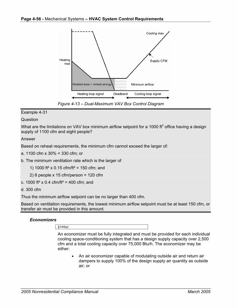
Page 4-56 - Mechanical Systems – HVAC System Control Requirements
2005 Nonresidential Compliance Manual March 2005
Figure 4-13 – Dual-Maximum VAV Box Control Diagram
Example 4-31
Question
What are the limitations on VAV box minimum airflow setpoint for a 1000 ft2 office having a design supply of 1100 cfm and eight people?
Answer
Based on reheat requirements, the minimum cfm cannot exceed the larger of:
a. 1100 cfm x 30% = 330 cfm; or
b. The minimum ventilation rate which is the larger of
1) 1000 ft² x 0.15 cfm/ft² = 150 cfm; and
2) 8 people x 15 cfm/person = 120 cfm
c. 1000 ft² x 0.4 cfm/ft² = 400 cfm; and
d. 300 cfm
Thus the minimum airflow setpoint can be no larger than 400 cfm.
Based on ventilation requirements, the lowest minimum airflow setpoint must be at least 150 cfm, or transfer air must be provided in this amount.
Economizers §144(e)
An economizer must be fully integrated and must be provided for each individual cooling space-conditioning system that has a design supply capacity over 2,500 cfm and a total cooling capacity over 75,000 Btu/h. The economizer may be either:
• An air economizer capable of modulating outside air and return air dampers to supply 100% of the design supply air quantity as outside air; or
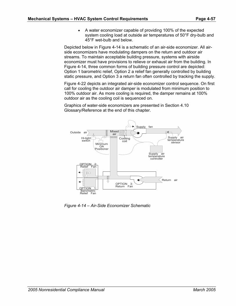
Mechanical Systems – HVAC System Control Requirements Page 4-57
2005 Nonresidential Compliance Manual March 2005
• A water economizer capable of providing 100% of the expected system cooling load at outside air temperatures of 50°F dry-bulb and 45°F wet-bulb and below.
Depicted below in Figure 4-14 is a schematic of an air-side economizer. All air-side economizers have modulating dampers on the return and outdoor air streams. To maintain acceptable building pressure, systems with airside economizer must have provisions to relieve or exhaust air from the building. In Figure 4-14, three common forms of building pressure control are depicted: Option 1 barometric relief, Option 2 a relief fan generally controlled by building static pressure, and Option 3 a return fan often controlled by tracking the supply.
Figure 4-22 depicts an integrated air-side economizer control sequence. On first call for cooling the outdoor air damper is modulated from minimum position to 100% outdoor air. As more cooling is required, the damper remains at 100% outdoor air as the cooling coil is sequenced on.
Graphics of water-side economizers are presented in Section 4.10 Glossary/Reference at the end of this chapter.
Figure 4-14 – Air-Side Economizer Schematic
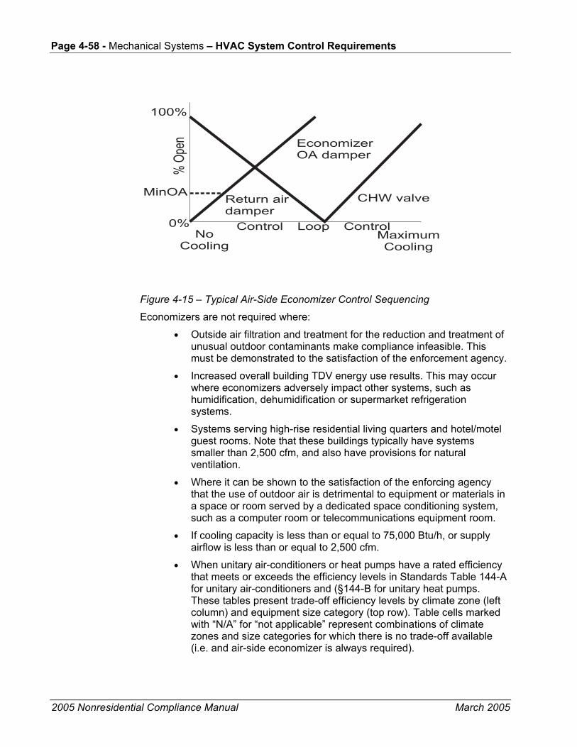
Page 4-58 - Mechanical Systems – HVAC System Control Requirements
2005 Nonresidential Compliance Manual March 2005
Figure 4-15 – Typical Air-Side Economizer Control Sequencing
Economizers are not required where:
• Outside air filtration and treatment for the reduction and treatment of unusual outdoor contaminants make compliance infeasible. This must be demonstrated to the satisfaction of the enforcement agency.
• Increased overall building TDV energy use results. This may occur where economizers adversely impact other systems, such as humidification, dehumidification or supermarket refrigeration systems.
• Systems serving high-rise residential living quarters and hotel/motel guest rooms. Note that these buildings typically have systems smaller than 2,500 cfm, and also have provisions for natural ventilation.
• Where it can be shown to the satisfaction of the enforcing agency that the use of outdoor air is detrimental to equipment or materials in a space or room served by a dedicated space conditioning system, such as a computer room or telecommunications equipment room.
• If cooling capacity is less than or equal to 75,000 Btu/h, or supply airflow is less than or equal to 2,500 cfm.
• When unitary air-conditioners or heat pumps have a rated efficiency that meets or exceeds the efficiency levels in Standards Table 144-A for unitary air-conditioners and (§144-B for unitary heat pumps. These tables present trade-off efficiency levels by climate zone (left column) and equipment size category (top row). Table cells marked with “N/A” for “not applicable” represent combinations of climate zones and size categories for which there is no trade-off available (i.e. and air-side economizer is always required).

Mechanical Systems – HVAC System Control Requirements Page 4-59
2005 Nonresidential Compliance Manual March 2005
If an economizer is required, it must be designed and equipped with controls that do not increase the building heating energy use during normal operation. This prohibits the application of single-fan dual-duct systems and traditional multizone systems using the Prescriptive Approach of compliance (see Figure 4-17). With these systems the operation of the economizer to pre-cool the air entering the cold deck also precools the air entering the hot deck and thereby increases the heating energy. An exception allows these systems when at least 75% of the annual heating is provided by site-recovered or site-solar energy §144(e)2.A.
The economizer controls must also be fully integrated into the cooling system controls so that the economizer can provide partial cooling even when mechanical cooling is required to meet the remainder of the load §144(e)2.B. On packaged units with stand-alone economizers, a two-stage thermostat is necessary to meet this requirement.
The requirement that economizers be designed for concurrent operation is not met by some popular water economizer systems, such as those that use the chilled water system to convey evaporative-cooled condenser water for “free” cooling. Such systems can provide 100% of the cooling load, but when the point is reached where condenser water temperatures cannot be sufficiently cooled by evaporation, the system controls throw the entire load to the mechanical chillers. Because this design cannot allow simultaneous economizer and refrigeration system operation, it does not meet the requirements of this section.
Air-side economizers are required to have high-limit shut-off controls that comply with Table 144-C of the Standards. This table has four columns:
1. The first column identifies the high limit control category. There are five categories representing enthalpy and dry-bulb controls (fixed and differential and the electronic enthalpy controller.
2. The second column represents the California climate zone. “All” indicates that this control type complies in every California climate.
3. The third and fourth columns present the high-limit control setpoints required.
Fixed enthalpy controls are prohibited in climate zones 01, 02, 03, 05, 11, 13, 14, 15 & 16. In these climates, the enthalpy in the return air varies throughout the year and cannot be accurately represented by a fixed setpoint.
Air economizers, water economizers and integrated controls are discussed in more detail at the beginning of this Chapter.
Chapter 8, Acceptance Requirements, describe mandated acceptance test requirements for economizers.
To reduce the time required to perform the economizer acceptance test, factory calibration and a calibration certificate of economizer control sensors (outdoor air temperature, return air temperature, etc.

Page 4-60 - Mechanical Systems – HVAC System Control Requirements
2005 Nonresidential Compliance Manual March 2005
Figure 4-16 – Economizer Flowchart

Mechanical Systems – HVAC System Control Requirements Page 4-61
2005 Nonresidential Compliance Manual March 2005
Figure 4-17 – Single-Fan Dual-Duct System
Example 4-32
Question
If my design conditions are 94°Fdb/82°Fwb can I use my design cooling loads to size a water-side economizer?
Answer
No. The design cooling load calculations must be rerun with the outdoor air temperature set to 50°Fdb/45°Fwb. The specified tower, as well as cooling coils and other devices, must be checked to determine if it has adequate capacity at this lower load and wet-bulb condition. Example 4-33
Question
Will a strainer cycle water-side economizer meet the prescriptive economizer requirements? (Refer to Figure 4-4.)
Answer
No. It cannot be integrated to cool simultaneously with the chillers.
Example 4-34
Question
Does a 12 ton packaged AC unit in climate zone 10 need an economizer?
Answer
Yes. However that requirement can be waived per exception 5 to §144(e)1 if the AC unit’s efficiency is greater than or equal to an EER of 11.9. Refer to Standards Table 144-A.
Supply Pressure Controls for VAV Systems §144(c)2
VAV systems with motors > = 10 hp are required to have either:
• A mechanical or electrical variable speed drive fan motor;
• Vane axial fan with variable pitch blades; or

Page 4-62 - Mechanical Systems – HVAC System Control Requirements
2005 Nonresidential Compliance Manual March 2005
• Include controls that limit the fan motor demand to no more than 30% of design wattage at 50% design air volume when the static pressure set point is one-third of total design static pressure.
Actual fan part load performance, available from the fan manufacturer, should be used to test for compliance with item 3) above. Figure 4-18 shows typical performance curves for different types of fans. As can be seen, both airfoil fans and backward inclined fans using either discharge dampers or inlet vanes consume more than 30% power at 50% flow when static pressure set point is one-third of total design static pressure using certified manufacturer’s test data. These fans will not normally comply with these requirements unless a variable speed drive is used.
VAV fan systems that don’t have DDC to the zone level are required to have the static pressure sensor located in a position such that the control setpoint is <=1/3 of the design static pressure of the fan. For systems without static pressure reset the further the sensor is from the fan the more energy will be saved. For systems with multiple duct branches in the distribution you must provide separate sensors in each branch and control the fan to satisfy the sensor with the greatest demand. When locating sensors, care should be taken to have at least one sensor between the fan and all operable dampers (e.g. at the bottom of a supply shaft riser before the floor fire/smoke damper) to prevent loss of fan static pressure control.
For systems with DDC to the zone level the sensor may be anywhere in the distribution system and the setpoint must be reset by the zone demand. Typically this is done by either controlling so that one VAV box damper is 95% open or using a “trim and respond” algorithm to continually reduce the pressure until one or more zones indicate that they are unable to maintain airflow rate setpoints.
Reset of supply pressure by demand not only saves energy but it also protects fans from operation in surge at low loads. Chapter 8, Acceptance Requirements, describes mandated acceptance test requirements for VAV system fan control

Mechanical Systems – HVAC System Control Requirements Page 4-63
2005 Nonresidential Compliance Manual March 2005
100
60
80
40
20
0 20 40 60 80 100
Perc
ent D
esig
n K
W
Percent Design CFM
FE
DC
B
A
A. Air foil or backward inclined centrifugal fan with discharge dampers B. Air foil centrifugal fan with inlet vanes C. Forward curved centrifugal fan with discharge dampers or riding curve D. Forward curved centrifugal fan with inlet vanes E. Vane-axial fan with variable pitch blades F. Any fan with variable speed drive (mechanical drives will be slightly less efficient)
Figure 4-18 – VAV Fan Performance Curve
Supply-Air Temperature Reset Control §144(f)
Mechanical space-conditioning systems supplying heated or cooled air to multiple zones must include controls that automatically reset the supply-air temperature in response to representative building loads, or to outdoor air temperature. The controls must be capable of resetting the supply-air temperature by at least 25% of the difference between the design supply-air temperature and the design room air temperature.
For example, if the design supply temperature is 55°F and the design room temperature is 75°F, then the difference is 20°F, and 25% is 5°F. Therefore, the controls must be capable of resetting the supply temperature from 55°F to 60°F.
Air distribution zones that are likely to have constant loads, such as interior zones, shall have airflow rates designed to meet the load at the fully reset temperature. Otherwise, these zones may prevent the controls from fully resetting the temperature, or will unnecessarily limit the hours when the reset can be used.
Supply air reset is required for VAV reheat systems that don’t use variable speed drives to control the supply fans. Although it is not required on VAV systems that have VSDs it is generally a good idea to provide it. With DDC controls the recommended control sequence is to lead with supply temperature setpoint reset in cool weather where reheat might dominate the equation and to keep the chillers off as long as possible, then return to a fixed low setpoint in warmer weather when the chillers are likely to be on. During reset, employ a demand-based control that uses the warmest supply air temperature that satisfies all of the zones in cooling.
This sequence is described as follows: during occupied mode, the setpoint is reset from T-min (53°F) when the outdoor air temperature is 70°F and above, proportionally up to T-max when the outdoor air temperature is 65°F and below. T-max shall range from 55°F to 65°F and shall be the output of a slow reverse-acting proportional-integral (PI) loop that maintains the cooling loop of the zone
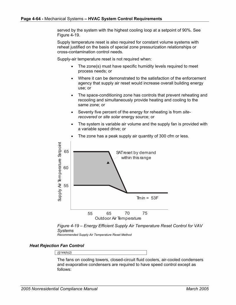
Page 4-64 - Mechanical Systems – HVAC System Control Requirements
2005 Nonresidential Compliance Manual March 2005
served by the system with the highest cooling loop at a setpoint of 90%. See Figure 4-19.
Supply temperature reset is also required for constant volume systems with reheat justified on the basis of special zone pressurization relationships or cross-contamination control needs.
Supply-air temperature reset is not required when:
• The zone(s) must have specific humidity levels required to meet process needs; or
• Where it can be demonstrated to the satisfaction of the enforcement agency that supply air reset would increase overall building energy use; or
• The space-conditioning zone has controls that prevent reheating and recooling and simultaneously provide heating and cooling to the same zone; or
• Seventy five percent of the energy for reheating is from site-recovered or site solar energy source; or
• The system is variable air volume and the supply fan is provided with a variable speed drive; or
• The zone has a peak supply air quantity of 300 cfm or less.
55 65
55
70
60
75
65
Outdoor Air Temperature
Supp
ly Ai
r Tem
pera
ture
Set
poin
t
Tmin = 53F
SAT reset by demandwithin this range
Figure 4-19 – Energy Efficient Supply Air Temperature Reset Control for VAV Systems Recommended Supply Air Temperature Reset Method
Heat Rejection Fan Control (§144(h)2)
The fans on cooling towers, closed-circuit fluid coolers, air-cooled condensers and evaporative condensers are required to have speed control except as follows:

Mechanical Systems – HVAC System Control Requirements Page 4-65
2005 Nonresidential Compliance Manual March 2005
• Fans powered by motors smaller than 7.5 hp
• Heat rejection devices included as an integral part of the equipment listed in the Standards Tables 112-A through 112-E. This includes unitary air-conditioners, unitary heat pumps, packaged chillers and packaged terminal heat pumps.
• Condenser fans serving multiple refrigerant circuits or flooded condensers.
• Up to 1/3 of the fans on a condenser or tower with multiple fans where the lead fans comply with the speed control requirement.
Where applicable, two-speed motors, pony motors or variable speed drives can be used to comply with this requirement.
Example 4-35
Question
A chilled water plant has a three-cell tower with 10 hp motors on each cell. Are speed controls required?
Answer
Yes. At minimum the designer must provide 2-speed motors, pony motors or variable speed drives on two of the three fans for this tower.
Hydronic System Controls §144(j)
The 2005 Standards features new requirements for hydronic system controls. These include:
• Design of systems for variable flow [§144(j)1].
• Chiller and boiler Isolation [§144(j)2 and 3].
• Chilled and hot water reset [§144(j)4].
• Isolation valves for water-loop heat pump systems [§144(j)5].
• VSDs for pumps serving variable flow systems [§144(j)6].
Each of these is described in the paragraphs that follow and Chapter 8, Acceptance Requirements, describes mandated acceptance test requirements for hydronic system controls.
Design of Systems for Variable Flow §144(j)1
Hot water and chilled water systems that have more than 3 control valves are required to be designed for variable flow. Aside from chiller plants serving ≤ 3 air handling units this covers most systems. Variable flow is provided by using 2-way control valves. The Standards only requires that flow is reduced to the

Page 4-66 - Mechanical Systems – HVAC System Control Requirements
2005 Nonresidential Compliance Manual March 2005
greater of 50% design flow or the minimum flow required by the equipment manufacturer for operation of the central plant equipment.
It should be noted that the primary loop on a primary/secondary or primary/secondary/tertiary system can be designed for constant flow even if the secondary or tertiary loop serves more than 3 control valves. This is allowed because the primary loop does not directly serve any coil control valves. However the secondary (and tertiary loops) of these systems must be designed for variable flow if they have 4 or more control valves.
The flow limitations are provided for primary-only variable flow chilled water systems where a minimum flow is typically required to keep a chiller on-line. In these systems minimum flow can be provided with either a bypass with a control valve or some 3-way valves to ensure minimum flow at all times. The system with a bypass valve is more efficient as it only provides bypass when absolutely required to keep the plant on line.
For hot water systems application of slant-tube or bent tube boilers will provide the greatest flow turndown. Typically copper fin tube boilers require a higher minimum flow.
Chiller and Boiler Isolation(§144(j)2 and 3
Plants with multiple chillers or boilers are required to provide either isolation valves or dedicated pumps and check valves to ensure that flow will only go through the chillers or boilers that are staged on. Chillers that are piped in series for the purpose of increased temperature differential shall be considered as one chiller.
Chilled and Hot Water Reset §144(j)4
Similar to the requirements for supply air temperature reset, chilled and hot water systems that have a design capacity > 500,000 Btu/h are required to provide controls to reset the hot or cold water temperature setpoints as a function of building loads or the outdoor air temperature. This reset can be achieved either using a direct indication of demand (usually cooling or heating valve position) or an indirect indication of demand (typically outdoor air temperature). On systems with DDC controls reset using valve position is recommended.
There is an exception to this requirement for hydronic systems that are designed for variable flow complying with §144(j)1.
Isolation Valves for Water-Loop Heat Pump Systems §144(j)5
Water-loop heat pump systems that have a design circulation pump brake horsepower >5 bhp are required to be provided with 2-way isolation valves that close whenever the compressor is off. These systems are also required to be provided with the variable speed drives and pressure controls described in the following section.
Although this is not required on central tenant condenser water systems (for water-cooled AC units and HPs) it is a good idea to provide the 2-way isolation

Mechanical Systems – HVAC System Requirements Page 4-67
2005 Nonresidential Compliance Manual March 2005
valves on these systems as well. In addition to providing pump energy savings these 2-way valves can double as head-pressure control valves to allow aggressive condenser water reset for energy savings in chilled water plants that are also cooled by the towers. .
VSDs for Pumps Serving Variable Flow Systems §144(j)6
Pumps on variable flow systems that have a design circulation pump brake horsepower > 5 bhp are required to have variable speed drives that are controlled to provide pressure to either the most remote heat exchanger or the heat exchanger requiring the most pressure. This includes chilled water systems, condenser water systems serving water-cooled air conditioning (AC) loads and water-loop heat pump systems.
Exceptions are provided for hot-water systems and condenser water systems that only serve water-cooled chillers. The hot water systems are exempted because the heat from the added pumping energy of the pump riding the curve provides a beneficial heat that reduces the boiler use. This reduces the benefit from the reduced pumping energy.
4.5.3 Acceptance Requirements
There are a number of acceptance requirements related to control systems. These include:
• Automatic time switch control devices.
• Constant volume package unit.
• Air-side economizers.
• VAV supply fan controls.
• Hydronic system controls.
These tests are described in Chapter 8, Acceptance Requirements, as well as the ACM Manual Appendices NG and NJ.
4.6 HVAC System Requirements The HVAC system requirements are all prescriptive requirements and may be modified in the whole building performance process. There are no mandatory measures or acceptance requirements.
4.6.1 Sizing and Equipment Selection §144(a)
The Standards require that mechanical heating and cooling equipment (including electric heaters and boilers) be the smallest size available, within the available options of the desired equipment line, that meets the design heating and cooling loads of the building or spaces being served. Depending on the

Page 4-68 - Mechanical Systems – HVAC System Requirements
2005 Nonresidential Compliance Manual March 2005
equipment, oversizing can be either a penalty or benefit to energy usage. For vapor compression equipment, gross oversizing can drastically increase the energy usage and in some cases cause premature failure from short cycling of compressors. Boilers and water-heaters generally suffer lower efficiencies and higher standby losses if they are oversized. On the other hand, cooling towers, cooling coils, and variable speed driven cooling tower fans can actually improve in efficiency if oversized. Oversized distribution ductwork and piping can reduce system pressure losses and reduce fan and pump energy.
When equipment is offered in size increments, such that one size is too small and the next is too large, the larger size may be selected.
Packaged HVAC equipment may serve a space having substantially different heating and cooling loads. The unit size should be selected on the larger of the loads, based on either capacity or airflow. The capacity for the other load should be selected as required to meet the load, or if very small, should be the smallest capacity available in the selected unit. For example, packaged air-conditioning units with gas heat are usually sized on the basis of cooling loads. The furnace is sized on the basis of airflow, and is almost always larger than the design heating load.
Equipment may be oversized provided one or more of the following conditions are met:
• It can be demonstrated to the satisfaction of the enforcing agency that oversizing will not increase building source energy use; or
• Oversizing is the result of standby equipment that will operate only when the primary equipment is not operating. Controls must be provided that prevent the standby equipment from operating simultaneously with the primary equipment; or
• Multiple units of the same equipment type are used, each having a capacity less than the design load, but in combination having a capacity greater than the design load. Controls must be provided to sequence or otherwise optimally control the operation of each unit based on load.
4.6.2 Load Calculations §144(b)
For the purposes of sizing HVAC equipment, the designer shall use all of the following criteria for load calculations:
• The heating and cooling system design loads must be calculated in accordance with the procedures described in the ASHRAE Handbook, 2001, Fundamentals Volume. Other load calculation methods, e.g. ACCA, SMACNA, etc., are acceptable provided that the method is ASHRAE-based. When submitting load calculations of this type, the designer must accompany the load calculations with a written affidavit certifying that the method used is ASHRAE-based. If the designer is unclear as to whether or not the calculation method is ASHRAE-based, the vendor or organization providing the calculation

Mechanical Systems – HVAC System Requirements Page 4-69
2005 Nonresidential Compliance Manual March 2005
method should be contacted to verify that the method is derived from ASHRAE.
• Indoor design conditions of temperature and relative humidity for general comfort applications are not explicitly defined. Designers are allowed to use any temperature conditions within the “comfort envelope” defined by ANSI/ASHRAE 55-1992 or Chapter 8 of the ASHRAE Handbook, 2003, Fundamentals Volume. Winter humidification or summer dehumidification is not required.
• Outdoor design conditions shall be selected from Joint Appendix II, which is based on data from the ASHRAE Climatic Data for Region X, for the following design conditions:
• Heating design temperatures shall be no lower than the temperature listed in the Heating Winter Median of Extremes value.
• Cooling design temperatures shall be no greater than the 0.5% Cooling Dry Bulb and Mean Coincident Wet Bulb values.
• Outdoor Air Ventilation loads must be calculated using the ventilation rates required in §121. At minimum, the ventilation rate will be 15 cfm/person or 0.15 cfm/ft², whichever is greater.
• Envelope heating and cooling loads must be calculated using envelope characteristics including square footage, thermal conductance, solar heat gain coefficient and air leakage, consistent with the proposed design.
• Lighting loads shall be based on actual design lighting levels or power densities consistent with §146.
• People sensible and latent gains must be based on the expected occupant density of the building and occupant activities. If ventilation requirements are based on a cfm/person basis, then people loads must be based on the same number of people as ventilation. Sensible and latent gains must be selected for the expected activities as listed in ASHRAE Handbook, 2001, Fundamentals Volume, Chapter 29, Table 1.
• Loads caused by a process shall be based on actual information (not speculative) on the intended use of the building.
• Miscellaneous equipment loads include such things as duct losses, process loads and infiltration and shall be calculated using design data compiled from one or more of the following sources:
• Actual information based on the intended use of the building; or
• Published data from manufacturer’s technical publications and from technical societies, such as the ASHRAE Handbook, 2003 HVAC Applications Volume; or
• Other data based on the designer’s experience of expected loads and occupancy patterns.
• Internal heat gains may be ignored for heating load calculations.
Page 4-70 - Mechanical Systems – HVAC System Requirements
2005 Nonresidential Compliance Manual March 2005
A safety factor of up to 10% may be applied to design loads to account for unexpected loads or changes in space usage.
• Other loads such as warm-up or cool-down shall be calculated using one of the following methods:
A method using principles based on the heat capacity of the building and its contents, the degree of setback, and desired recovery time; or
The steady state design loads may be increased by no more than 30% for heating and 10% for cooling. The steady state load may include a safety factor of up to 10% as discussed above in Item 11.
The combination of safety factor and other loads allows design cooling loads to be increased by up to 21% (1.10 safety x 1.10 other), and heating loads by up to 43% (1.10 safety x 1.30 other).
Example 4-36
Question
Do the sizing requirements restrict the size of duct work, coils, filter banks, etc. in a built-up system?
Answer
No. The intent of the Standards is to limit the size of equipment, which if oversized will consume more energy on an annual basis. Coils with larger face areas will usually have lower pressure drops than otherwise, and may also allow the chilled water temperature to be higher, both of which may result in a decrease in energy usage. Larger filter banks will also usually save energy. Larger duct work will have lower static pressure losses, which may save energy, depending on the duct’s location, length, and degree of insulation.
Oversizing fans, on the other hand, may or may not improve energy performance. An oversized airfoil fan with inlet vanes will not usually save energy, as the part load characteristics of this device are poor. But the same fan with a variable frequency drive may save energy. Controls are also an important part of any system design.
The relationship between various energy consuming components may be complex, and is left to the designer’s professional judgment. Note however, that when components are oversized, it must be demonstrated to the satisfaction of the enforcement agency that energy usage will not increase.
4.6.3 Fan Power Consumption §144(c)
Maximum fan power is regulated in individual fan systems where the total power of the supply, return and exhaust fans within the fan system exceed 25 horsepower at design conditions (see Section 4.10 for definitions). A system consists of only the components that must function together to deliver air to a given area; fans that can operate independently of each other comprise separate systems. Included are all fans associated with moving air from a given space-conditioning system to the conditioned spaces and back to the source, or to exhaust it to the outdoors.
Mechanical Systems – HVAC System Requirements Page 4-71
2005 Nonresidential Compliance Manual March 2005
The 25 horsepower total criteria apply to:
• All supply and return fans within the space-conditioning system that operate at peak load conditions.
• All exhaust fans at the system level that operate at peak load conditions. Exhaust fans associated with economizers are not counted provided they do not operate at peak conditions.
• Fan-powered VAV boxes, if these fans run during the cooling peak. This is always the case for fans in series type boxes. Fans in parallel boxes may be ignored if they are controlled to operate only when zone heating is required, and are normally off during the cooling peak.
• Elevator equipment room exhausts, or other exhausts that draw air from a conditioned space, through an otherwise unconditioned space, to the outdoors.
• Computer room units.
The criteria are applied individually to each space-conditioning system. In buildings having multiple space-conditioning systems, the criteria applies only to the systems having fans whose total demand exceeds 25 horsepower.
Not included are fans not directly associated with moving conditioned air to or from the space-conditioning system, or fans associated with a process within the building.
For the purposes of the 25 horsepower criteria, horsepower is the brake horsepower as listed by the manufacturer for the design conditions, plus any losses associated with the drive, including belt losses or variable frequency drive losses. If the brake horsepower is not known, then the nameplate horsepower should be used.
If drive losses are not known, the designer may assume that direct drive efficiencies are 1.0, and belt drives are 0.97. Variable speed drive efficiency should be taken from the manufacturer’s literature; if it includes a belt drive, it should be multiplied by 0.97.
Total fan horsepower need not include the additional power demand caused solely by air treatment or filtering systems with final pressure drops of more than 1 in. water gauge (w.g.). It is assumed that conventional systems may have filter pressure drops as high as 1 in. w.g.; therefore only the horsepower associated with the portion of the pressure drop exceeding 1 in., or fan system power caused solely by process loads, may be excluded.
For buildings whose systems exceed the 25 horsepower criteria, the total space-conditioning system power requirements are:
1. Constant volume fan systems. The total fan power index at design conditions of each fan system with total horsepower over 25 horsepower shall not exceed 0.8 watts per cfm of supply air.
2. Variable air volume (VAV) systems.

Page 4-72 - Mechanical Systems – HVAC System Requirements
2005 Nonresidential Compliance Manual March 2005
A. The total fan power index at design conditions of each fan system with total horsepower over 25 horsepower shall not exceed 1.25 watts per cfm of supply air; and
B. Individual VAV fans with motors 10 horsepower or larger shall meet one of the following:
i. The fan motor shall be driven by a mechanical or electrical variable speed drive.
ii. The fan shall be a vane-axial fan with variable pitch blades.
iii. For prescriptive compliance, the fan motor shall include controls that limit the fan motor demand to no more than 30% of the total design wattage at 50% of design air volume when static pressure set point equals 1/3 of the total design static pressure, based on certified manufacturer's test data.
C. Static Pressure Sensor Location. Static pressure sensors used to control variable air volume fans shall be placed in a position such that the controller set point is no greater than one-third the total design fan static pressure, except for systems with zone reset control complying with 144 (c) 2 D. If this results in the sensor being located downstream of major duct splits, multiple sensors shall be installed in each major branch with fan capacity controlled to satisfy the sensor furthest below its setpoint.
D. Set Point Reset. For systems with direct digital control of individual zone boxes reporting to the central control panel, static pressure set point shall be reset based on the zone requiring the most pressure; i.e., the set point is reset lower until one zone damper is nearly wide open.
3. Air-treatment or filtering systems. For systems with air-treatment or filtering systems, calculate the adjusted fan power index using equation 144-A:
EQUATION 144-A ADJUSTED FAN POWER INDEX
Adjusted fan power index = Fan power index x Fan Adjustment
Fan Adjustment = ·1-(SPa - 1)/ SPf.
WHERE:
SPa = Air pressure drop across the air-treatment or filtering system.
SPf = Total pressure drop across the fan.
4. Fan motors of series fan-powered terminal units. Fan motors of series fan-powered terminal units 1 horsepower or less in shall

Mechanical Systems – HVAC System Requirements Page 4-73
2005 Nonresidential Compliance Manual March 2005
be electronically-commutated motors or shall have a minimum motor efficiency of 70% when rated in accordance with NEMA Standard MG 1-1998 Rev. 2 at full load rating conditions.
The total system power demand is based on brake horsepower at design static and cfm, and includes drive losses and motor efficiency. If the motor efficiency is not known, values from ACM Manual Appendix NC may be used.
Figure 4-20 – Fan Power Flowchart

Page 4-74 - Mechanical Systems – HVAC System Requirements
2005 Nonresidential Compliance Manual March 2005
Example 4-37
Question
In the system depicted below, which fans are included in the fan power criteria?
Answer
The fans included are those that operate during the design cooling load. These include the supply fan, the return fan, the series fan-powered VAV box(es), the general exhaust fan, and conference room exhaust fans other than those that are manually controlled. The parallel fan-powered VAV box(es) are not included as those fans only operate during a call for zone heating.
Example 4-38
Question
If a building has five zones with 15,000 cfm air handlers that are served by a common central plant, and each air handler has a 15 HP supply fan, does the 25 HP limit apply?
Answer
No. Each air handler, while served by a common central plant, is a separate fan system. Since the demand of each air handler is only 15 HP, the 25 HP criteria does not apply.
Example 4-39
Question
The space-conditioning system in a laboratory has a 30% filter with a design pressure drop at change out of 0.5 in. w.g., and an 80% filter with a design pressure drop of 1.2 in. w.g. The design total static pressure of the fan is 5.0 inch w.g. What percentage of the power may be excluded from the W/cfm calculation?
Answer
The total filter drop at change out (final pressure drop) is 0.5 in. + 1.2 in. = 1.7 in. w.g. The amount that may be excluded is 1.7 in.-1.0 in. = 0.7 in. w.g. The percentage of the horsepower that may be excluded is 0.7 in./5.0 in. = 14%
Mechanical Systems – HVAC System Requirements Page 4-75
2005 Nonresidential Compliance Manual March 2005
If the supply fan requires 45 brake horsepower, the adjusted horsepower of the supply fan in the W/cfm calculation is
45 BHP x (1 - 14%) = 38.7 BHP
The horsepower of any associated return or exhaust fan is not adjusted by this factor, as the filters have no impact on these fans.
Example 4-40
Question
What is the maximum allowed power consumption for the fans in a VAV bypass system?
Answer
A VAV bypass, while variable volume at the zone level, is constant volume at the fan level. If the total fan power demand of this system exceeds 25 HP, then the fan power may not exceed 0.8 W/cfm.
Example 4-41
Question
What is the power consumption of a 20,000 cfm VAV system having an 18 BHP supply fan, a 5 BHP return fan, a 3 BHP economizer relief fan, a 2 HP outside air ventilation fan and a 1 HP toilet exhaust fan? Note that the exhaust and outside air ventilation fans are direct drive and listed in HP not BHP. The supply and return fans are controlled with variable frequency drives having an efficiency of 96%.
Answer
The economizer fan is excluded provided it does not run at the time of the cooling peak.
Power consumption is then based on the supply; return, outdoor and toilet exhaust fans. The ventilation fan is direct drive so its efficiency is 1.0. The supply and return fans have default drive efficiencies of 0.97. From Tables NC-1 and NC-2 from ACM Manual Appendix NC, the assumed efficiencies of the motors are 91.7% and 87.5% for a 25 and 7.5 HP 4-pole motor respectively. Fan power demand in units of horsepower must first be calculated to determine whether the requirements apply:
a. 18 BHP / (0.97 x 0.917 x 0.96) = 21.1.0 HP
b. 5 BHP / (0.97 x 0.875 x 0.96) = 6.1 HP
Total power consumption, adjusted for efficiencies, is calculated as:
21.1.0 HP + 6.1 HP + 2 HP + 1 HP = 30.2 HP
Since this is larger than 25 HP, the limitations apply. W/cfm is calculated as:
30.2 HP x 746 W/cfm/20,000 cfm = 1.13 W/cfm
The system complies because power consumption is below 1.25 Wcfm. Note that, while this system has variable frequency drives, they are only required by the Standards for the 18 BHP fan since each other fan is less than 10 HP.
Page 4-76 - Mechanical Systems – HVAC System Requirements
2005 Nonresidential Compliance Manual March 2005
4.6.4 ECM Motors for Series Style VAV Boxes §144(c)4
Series style fan powered boxes with motors ≤ 1 hp are required to have either electrically commuted motors (ECM) or shall have a minimum motor efficiency of 70% when rated in accordance with NEMA Standard MG 1-1998 Rev. 2 at full load rating conditions. This is a new requirement in 2005.
4.6.5 Electric-Resistance Heating §144(g), 149
The Standards strongly discourage the use of electric-resistance space heat. Electric-resistance space heat is not allowed in the prescriptive approach except where:
• Site-recovered or site-solar energy provides at least 60% of the annual heating energy requirements; or
• A heat pump is supplemented by an electric-resistance heating system, and the heating capacity of the heat pump is more than 75% of the design heating load at the design outdoor temperature, determined in accordance with the Standards; or
• The total capacity of all electric-resistance heating systems serving the entire building is less than 10% of the total design output capacity of all heating equipment serving the entire building; or
• The total capacity of all electric-resistance heating systems serving the building, excluding those that supplement a heat pump, is no more than 3 kW; or
• An electric-resistance heating system serves an entire building that:
• Is not a high-rise residential or hotel/motel building; and
• Has a conditioned floor area no greater than 5,000 ft2; and
• Has no mechanical cooling; and
• Is in an area where natural gas is not currently available and an extension of a natural gas system is impractical, as determined by the natural gas utility.
• In alterations where the existing mechanical systems use electric reheat (when adding variable air volume boxes) added capacity cannot exceed 20% of the existing installed electric capacity, under any one permit application.
• In an addition where the existing variable air volume system with electric reheat is being expanded the added capacity cannot exceed 50% of the existing installed electric reheat capacity under any one permit.
The Standards in effect allow a small amount of electric-resistance heat to be used for local space heating or reheating (provided reheat is in accordance with these regulations).

Mechanical Systems – HVAC System Requirements Page 4-77
2005 Nonresidential Compliance Manual March 2005
Example 4-42
Question
If a heat pump is used to condition a building having a design heating load of 100,000 Btu/h at 35°F, what are the sizing requirements for the compressor and heating coils?
Answer
The compressor must be sized to provide at least 75% of the heating load at the design heating conditions, or 75,000 Btu/h at 35°F. The Standards do not address the size of the resistance heating coils. Normally, they will be sized based on heating requirements during defrost.
4.6.6 Cooling Tower Flow Turndown § 144(h)3
The Standards require that open cooling towers with multiple condenser water pumps be designed so that all cells can be run in parallel with the larger of
• The flow that’s produced by the smallest pump, or
• Thirty three percent of the design flow for the cell.
Note that in a large plant at low load operation you would typically run less than all of the cells at once. This is allowed in the standard.
Cooling towers are very efficient at unloading (the fan energy drops off as the cube of the airflow). It is always more efficient to run the water through as many cells as possible; 2 fans at ½ speed use less than 1/3 of the energy of 1 fan at full speed for the same load. Unfortunately there is a limitation with flow on towers, the flow must be sufficient to provide full coverage of the fill. If the nozzles don’t fully wet the fill, air will go through the dry spots providing no cooling benefit and cause the water at the edge of the dry spot to flash evaporate depositing dissolved solids on the fill.
Luckily the cooling tower manufacturers do offer low-flow nozzles (and weirs on basin type towers) to provide better flow turndown. This typically only costs $100 to $150 per tower cell. As it can eliminate the need for a tower isolation control point this provides energy savings at a reduced first cost.
Example 4-43
Question
If a large central plant has five equally sized chillers and five equally sized cooling tower cells do all of the cooling tower cells need to operate when only one chiller is on-line?
Answer
No you would probably only run three cells with one chiller. The cooling tower cells must be designed to run at 33% of their nominal design flow. With two to five chillers running you would run all of the cells of cooling tower. With only one chiller running you would run three cells. In each case you would need to keep the tower flow above the minimum that it was designed for.

Page 4-78 - Mechanical Systems – HVAC System Requirements
2005 Nonresidential Compliance Manual March 2005
4.6.7 Centrifugal Fan Limitation § 144(h)4
Open cooling towers with a combined rated capacity of 900 gpm and greater at 95°F condenser water return, 85°F condenser water supply and 75°F outdoor wet-bulb temperature are prohibited to use centrifugal fans. The 95°F condenser water return, 85°F condenser water supply and 75°F outdoor wet-bulb temperature are test conditions for determining the rated flow capacity in gpm. Centrifugal fans use approximately twice the energy as propeller fans for the same duty. There are a couple of exceptions to this requirement.
• Cooling towers that are ducted (inlet or discharge) or have an external sound trap that requires external static pressure capability.
• Cooling towers that meet the energy efficiency requirement for propeller fan towers in §112, Standards Table 112-G.
Centrifugal fans may be used on closed circuit fluid coolers.
As with all prescriptive requirements centrifugal fan cooling towers may be used when complying with the performance method. The budget building will be modeled using propeller towers.
4.6.8 Air Cooled Chillers §144(i)
New central cooling plants and cooling plant expansions that are greater than or equal to 300 tons in installed capacity will be limited on the use of air-cooled chillers. For plant expansions the 300 ton trigger applies only to the newly installed equipment (exception to §149 (b) 1 C). Above this size threshold, air cooled chillers can be provided for ≤ 100 tons of capacity.
In the studies provided to support this requirement, air cooled chillers always provided a higher life-cycle cost than water cooled chillers even accounting for the water and chemical treatment costs.
There are a few exceptions to this requirement:
• Where the designer demonstrates to the authority having jurisdiction that the water quality at the building site fails to meet manufacturer’s specifications for the use of water-cooled equipment.
• Plants serving chilled or ice thermal energy storage systems.
• Air cooled chillers with minimum efficiencies approved by the Commission pursuant to §10-109 (d).
The first exception recognizes that some parts of the State have exceptionally high quantities of dissolved solids that could foul systems or cause excessive chemical treatment or blow down.
The second exception addresses the fact that air-cooled chillers can operate very efficiently at low ambient air temperatures. Since TES systems operate for long hours at night, these systems may be as efficient as a water-cooled plant.

Mechanical Systems – Service Water Heating Page 4-79
2005 Nonresidential Compliance Manual March 2005
Note that the chiller must be provided with head pressure controls to achieve these savings.
The third exception was provided in the event that an exceptionally high efficiency air cooled chiller was developed. None of the high-efficiency air-cooled chillers currently evaluated are as efficient as a water-cooled systems using the lowest chiller efficiency allowed by §112.
4.6.9 Historic Buildings
Exception 1 to §100(a) states that qualified historic buildings, as defined in the California Historical Building Code (Title 24, Part 8 or California Building Code, Title 24, Part 2, Volume I, Chapter 34, Division II) are not covered by the Standards. However, non-historical components of the buildings, such as new or replacement mechanical, plumbing, and electrical (including lighting) equipment, additions and alterations to historic buildings, and new appliances in historic buildings may need to comply with Building Energy Efficiency Standards and Appliance Standards, as well as other codes. For more information about energy compliance requirements for Historic Buildings, see Section 1.7.1, Building Types Covered, in Chapter 1, the Overview of this manual.
4.7 Service Water Heating All of the requirements for service hot water are mandatory measures, except for high-rise residential, which must comply with the low-rise residential standards (see Section 4.7.4). There are no acceptance requirements for water heating systems or equipment.
4.7.1 Service Water Systems
Efficiency and Control §113(a)
Any service water heating equipment must have integral automatic temperature controls that allow the temperature to be adjusted from the lowest to the highest allowed temperature settings for the intended use as listed in Table 2, Chapter 49 of the 2003 ASHRAE Handbook, HVAC Applications Volume.
Water heating systems in high-rise residential buildings must meet the energy budget requirements of the Residential Standards. Service water heaters installed in residential occupancies need not meet the temperature control requirement of §113(a)1.
Multiple Temperature Usage §113(c)1
On systems that have a total capacity greater than 167,000 Btu/h, outlets requiring higher than service water temperatures as listed in the 2003 ASHRAE Handbook, HVAC Applications Volume shall have separate remote heaters,

Page 4-80 - Mechanical Systems – Service Water Heating
2005 Nonresidential Compliance Manual March 2005
heat exchangers, or boosters to supply the outlet with the higher temperature. This requires the primary water heating system to supply water at the lowest temperature required by any of the demands served for service water heating. All other demands requiring higher temperatures should be served by separate systems, or by boosters that raise the temperature of the primary supply.
Circulating Systems §113(c)2
Circulating service water systems must include a control capable of automatically turning off the circulating pump when hot water is not required. Such controls include automatic time switches, interlocks with HVAC time switches, occupancy sensors, and other controls that accomplish the intended purpose. Since residential occupancies have different supply requirements, a system serving a single dwelling unit does not have to meet the requirements of §113(c)2.
Public Lavatories §113(c)3
Lavatories in public restrooms must have controls that limit the water supply temperature to 110°F. Where a service water heater supplies only restrooms, the heater thermostat may be set to no greater than 110°F to satisfy this requirement; otherwise controls such as automatic mixing valves must be installed.
Storage Tank Insulation §113(c)4
Unfired water heater storage tanks and backup tanks for solar water heating systems must have:
• External insulation with an installed R-value of at least R-12; or
• Internal and external insulation with a combined R-value of at least R-16; or
• The heat loss of the tank based on an 80 degree F water-air temperature difference shall be less than 6.5 Btu per hour per ft2. This corresponds to an effective resistance of R-12.3.
Service Water Heaters in State Buildings §113(c)5
Any newly constructed building constructed by the State shall derive its service water heating from a system that provides at least 60% of the energy needed from site solar energy or recovered energy. This requirement may be waived for buildings where the State Architect determines that such systems are economically or physically infeasible.

Mechanical Systems – Service Water Heating Page 4-81
2005 Nonresidential Compliance Manual March 2005
4.7.2 Pool and Spa Heating Systems §114
Pool and spa heating systems must be certified by the manufacturer and listed by the Energy Commission as having:
• An efficiency that complies with the Appliance Efficiency Regulations; and
• An on-off switch mounted on the outside of the heater in a readily accessible location that allows the heater to be shut-off without adjusting the thermostat setting; and
• A permanent, easily readable, and weatherproof plate or card that gives instructions for the energy efficient operation of the pool or spa, and for the proper care of the pool or spa water when a cover is used; and
• No electric resistance heating. The only exceptions are:
• Listed packaged units with fully insulated enclosures and tight fitting covers that are insulated to at least R-6. Listed package units are defined in the National Electric Code and are typically sold as self-contained, UL Listed spas; or
• Pools or spas deriving at least 60% of the annual heating energy from site solar energy or recovered energy.
• No pilot light.

Page 4-82 - Mechanical Systems – Service Water Heating
2005 Nonresidential Compliance Manual March 2005
Figure 4-21 – Service Water Heating Flowchart
Pool and spa equipment must be installed with all of the following:
Mechanical Systems – Performance Approach Page 4-83
2005 Nonresidential Compliance Manual March 2005
• Solar heater connection - At least 36 inches of pipe between the filter and the heater must be provided to allow for the future addition of solar heating equipment.
• A cover must be provided for outdoor pools and outdoor spas, unless at least 60% of the annual heating energy is provided by site solar energy or recovered energy.
• Directional inlets must be provided for all pools that adequately mix the pool water.
• A time switch must be provided for pools to control the operation of the circulation pump, to allow the pump to be set to run in the off-peak demand period, and for the minimum time necessary to maintain the water in the condition required by applicable public health standards.
A time switch is not required where applicable public health standards require on-peak operation.
4.7.3 Service Water Heating Other Than High-rise Residential §145
A service water-heating system is considered to comply with the prescriptive requirements when all mandatory requirements are met for occupancies other than high-rise residential. Buildings that have both occupancies other than high-rise residential and high-rise residential must meet the service water heating requirements that apply to each occupancy.
4.7.4 High-rise Residential Service Water Heating
Service water heating systems serving high-rise residential occupancies must comply with §151(f)8. These requirements are described in the Residential Compliance Manual.
4.7.5 Acceptance Requirements
There are no acceptance requirements for service water heating systems.
4.8 Performance Approach Under the performance approach, the energy use of the building is modeled using a computer program approved by the California Energy Commission. This section presents some basic details on the modeling of building mechanical systems. Program users and those checking for enforcement should consult the most current version of the user’s manuals and associated compliance supplements for specific instructions on the operation of the program. All computer programs, however, are required to have the same basic modeling capabilities.

Page 4-84 - Mechanical Systems – Performance Approach
2005 Nonresidential Compliance Manual March 2005
More information on how to model the mechanical systems and components are included in Chapter 7, Performance Approach, and in the program vendor’s compliance supplement.
4.8.1 Compliance With a Computer Method
Each approved computer method automatically generates an energy budget by calculating the annual time dependent valuation (TDV) energy use of the standard design, a version of the proposed building incorporating all the prescriptive features.
A building complies with the Standards if the predicted TDV energy use of the proposed design is the same or less than the annual energy budget of the standard design. The energy budget includes a space-conditioning budget, lighting budget and water-heating budget.
TDV energy use defines the energy use of a building by converting the calculated energy consumption into TDV energy. Joint Appendix III describes the derivation of the TDV energy multipliers TDV energy multipliers adjust the calculated energy consumption of a building to account for the time dependent energy value of different fuels and inefficiencies in generating and distributing electricity.
The budget for space conditioning of the proposed building design varies according to the following specific characteristics:
• Orientation.
• Space-conditioning system type.
• Occupancy type.
• Climate zone.
Assumptions used by the computer methods in generating the energy budget are explained in the Alternative Calculation Methods Approval Manual and are based on features required for prescriptive compliance.
If any of the following equipment or systems are installed the acceptance tests must be conducted.
• Variable air volume systems.
• Constant volume systems.
• Package systems.
• Air distribution systems.
• Economizers.
• Demand control ventilation systems.
• Variable frequency drive fan systems.
• Hydronic control systems.
• Hydronic pump isolation controls and devices.
• Supply water reset controls.

Mechanical Systems – Additions and Alterations Page 4-85
2005 Nonresidential Compliance Manual March 2005
• Water loop heat pump control.
• Variable frequency drive pump systems.
• System programming.
• Time clocks.
A final occupancy permit can not be granted from the Building Department until all the test have been completed and pass. For more detail see Chapter 8, Acceptance Requirements.
4.8.2 Modeling Mechanical System Components
All alternative calculation methods (state-approved energy compliance software) have the capability to model various types of HVAC systems. In central systems, these modeling features affect the system loads seen by the plant. This is done by calculating the interactions between envelope, mechanical and electrical systems in the building and summarizing the energy required by the mechanical system to maintain space conditions.
For a complete description of how to model mechanical system components, refer to the compliance supplement for the approved computer program being used to demonstrate compliance.
4.9 Additions and Alterations When heating, cooling or service water heating are provided for an alteration or addition by expanding an existing system, that existing system need not comply with mandatory measures or prescriptive compliance requirements. However, any altered component must meet all applicable mandatory measures and space-conditioning ducts must meet the following.
4.9.1 Mandatory Measures – Additions and Alteration
All additions and alterations must comply with the following mandatory measures:
• §110 – Systems and Equipment—General
• §111 – Mandatory Requirements for Appliances Regulated by the Appliance Efficiency Regulations
• §112 – Mandatory Requirements for Space-Conditioning Equipment
• §113 – Mandatory Requirements for Service Water-Heating Systems and Equipment
• §114 – Mandatory Requirements for Pool and Spa Heating Systems and Equipment
• §115 – Natural Gas Central Furnaces, Cooking Equipment, and Pool and Spa Heaters: Pilot Lights Prohibited
Page 4-86 - Mechanical Systems – Additions and Alterations
2005 Nonresidential Compliance Manual March 2005
• §121 – Requirements for Ventilation
• §122 – Required Controls for Space-Conditioning Systems
• §123 – Requirements for Pipe Insulation
• §124 – Requirements for Air Distribution System Ducts and Plenums
• §125 – Required Nonresidential Mechanical System Acceptance
For more detailed information about the mandatory measures, refer to following sections of this chapter:
• 4.1.2 Compliance Approaches
• 4.2 Equipment Requirements
• 4.3 Ventilation Requirements
• 4.4 Pipe and Duct Distribution Systems
• 4.5 HVAC System Control Requirements
• 4.7 Service Water Heating
4.9.2 Prescriptive Requirements – Additions
All new additions must comply with the following prescriptive requirements:
• §144 – Prescriptive Requirements for Space Conditioning Systems
• §145 – Prescriptive Requirements for Service Water-Heating Systems
For more detailed information about the prescriptive requirements, refer to following sections of this chapter
• 4.1.2 Compliance Approaches
• 4.2 Equipment Requirements
• 4.5 HVAC System Control Requirements
• 4.6 HVAC System Requirements
• 4.6.5 Electric-Resistance Heating
Performance approach may also be used to demonstrate compliance for new additions. Refer to Chapter 7, Performance Approach, for more details.
Acceptance tests must be conducted on the following equipment or systems when installed in new additions:
• Variable air volume systems.
• Constant volume systems.
• Package systems.
• Air distribution systems.
• Economizers.
• Demand control ventilation systems.
Mechanical Systems – Additions and Alterations Page 4-87
2005 Nonresidential Compliance Manual March 2005
• Variable frequency drive fan systems.
• Hydronic control systems.
• Hydronic pump isolation controls and devices.
• Supply water reset controls.
• Water loop heat pump control.
• Variable frequency drive pump systems.
• System programming.
• Time clocks.
For more detail, see Chapter 8, Acceptance Requirements.
4.9.3 Prescriptive Requirements – Alterations
When new or replacement space-conditioning ducts are installed to serve an existing building, the new ducts shall meet the requirements of §124 (insulation levels, sealing materials and methods etc.).
If the ducts are part of a single zone constant volume system serving less than 5,000 ft2 and more than 25% of the ducts are outdoors or in unconditioned area including attic spaces and above insulated ceilings [the criteria of §144 (k) 1, 2, and 3], the duct system shall be sealed and tested for air leakage by the contractor. In most nonresidential buildings this requirement will not apply because the roof is insulated so that almost all of the duct length is running through directly or indirectly conditioned space.
If the ducts are in unconditioned space and have to be sealed, they must also be tested to leak no greater than 6% if the entire duct system is new or less than 15% if the duct system is added to a pre-existing duct system. The description of the test method can be found in Section 4.3.8.2 of Appendix NG of the Nonresidential ACM Manual. The air distribution acceptance test associated with this can be found in Appendix NJ 5.1 of the Nonresidential ACM Manual. This and all acceptance tests are described in Chapter 8 of this manual.
If the new ducts form an entirely new duct system directly connected to the air handler, the measured duct leakage shall be less than 6% of fan flow; or
If the new ducts are an extension of an existing duct system, the combined new and existing duct system shall meet one of the following requirements:
• The measured duct leakage shall be less than 15% of fan flow; or
• The duct leakage shall be reduced by more than 60% relative to the leakage prior to the equipment having been replaced and a visual inspection shall demonstrate that all accessible leaks have been sealed; or
• If it is not possible to meet the duct sealing requirements of Subsections a. or b., all accessible leaks shall be sealed and verified through a visual inspection by a certified HERS rater.
Page 4-88 - Mechanical Systems – Additions and Alterations
2005 Nonresidential Compliance Manual March 2005
EXCEPTION to Section 149 (b) 1 D ii: Existing duct systems that are extended, which are constructed, insulated or sealed with asbestos.
Once the ducts have been sealed and tested to leak less than the above amounts, a HERS rater will be contacted by the contractor to validate the accuracy of the duct sealing measurement on a sample of the systems repaired as described in the Nonresidential ACM Manual.
Similar requirements apply to ducts upon replacement of small (serving less than 5,000 sf) constant volume HVAC units or their components (including replacement of the air handler, outdoor condensing unit of a split system air conditioner or heat pump, cooling or heating coil, or the furnace heat exchanger). Again the duct sealing requirements are for those systems where over 25% of the duct area is outdoors or in unconditioned areas including attic spaces and above insulated ceilings.
One can avoid sealing the ducts by insulating the roof and sealing the attic vents as part of a larger remodel, thereby creating a conditioned space within which the ducts are located, and no longer meets the criteria of §144 k. Another alternative to duct sealing is to install a high EER air conditioner that will save as much energy as the duct system is losing though leaks. This trade-off can be calculated using the performance software or by using pre-calculated equipment efficiencies deemed comparable to duct sealing in Table 4-5 in Section 4.4.2.
When a space conditioning system is altered by the installation or replacement of space conditioning equipment (including replacement of the air handler, outdoor condensing unit of a split system air conditioner or heat pump, cooling or heating coil, or the furnace heat exchanger), the duct system that is connected to the new or replaced space conditioning equipment, if the duct system meets the criteria of Section 144 (k) 1, 2., and 3, shall be sealed, as confirmed through field verification and diagnostic testing in accordance with procedures for duct sealing of existing duct systems as specified in the Nonresidential ACM Manual, to one of the requirements of Section 149 (b) 1 D; and
EXCEPTION 1 to Section 149 (b) 1. E: Buildings altered so that the duct system no longer meets the criteria of Section 144 (k) 1, 2, and 3.
Ducts would no longer have to be sealed if the roof deck was insulated and attic ventilation openings sealed.
EXCEPTION 2 to Section 149 (b) 1 E: Duct systems that are documented to have been previously sealed as confirmed through field verification and diagnostic testing in accordance with procedures in the Nonresidential ACM Manual.
EXCEPTION 3 to Section 149 (b) 1 E: Existing duct systems constructed, insulated or sealed with asbestos.
There are new requirements in 2005 when using the performance approach for compliance, analyzing the whole building and making improvements in the existing building. Changes to the existing building are alterations and must meet the requirements of §149(b)2.B.
§149 (b) 2 B requires that the energy efficiency of either the building or permitted space shall be improved so that the building or permitted space meets

Mechanical Systems – Glossary/Reference Page 4-89
2005 Nonresidential Compliance Manual March 2005
the energy budget in Section 141 that would apply to the building or permitted space, if the building envelope was unchanged, except for roof alterations subject to Section 149 (b) 1 B, the roof alteration met the requirements of 149 (b) 1; and for any mechanical system alterations subject to Section 149(b) 1 C, D, E, the mechanical system alterations met the requirements of Section 149 (b) 1, and for any lighting system alterations subject to Section 149 (b) 1 F, the lighting system alteration met the requirements of Section 149 (b) 1; and for any service water-heating system alteration subject to Section 149 (b) 1 K, the service water-heating system met the requirements of Section 149 (b) 1.
When existing heating, cooling, or service water heating systems or components are moved within a building, the existing systems or components need not comply with mandatory measures nor with the prescriptive or performance compliance requirements.
Performance approach may also be used to demonstrate compliance for alterations. Refer to Chapter 7, Performance Approach, for more details.
Acceptance tests must be conducted on the following equipment or systems when installed in new additions:
• Variable air volume systems.
• Constant volume systems.
• Package systems.
• Air distribution systems.
• Economizers.
• Demand control ventilation systems.
• Variable frequency drive fan systems.
• Hydronic control systems.
• Hydronic pump isolation controls and devices.
• Supply water reset controls.
• Water loop heat pump control.
• Variable frequency drive pump systems.
• System programming.
• Time clocks.
For more detail, see Chapter 8, Acceptance Requirements.
4.10 Glossary/Reference Terms used in this chapter are defined in Joint Appendix I. Definitions that appear below either expand on the definition in Joint Appendix I or are terms that are not included in that appendix, but are included here as an aid in understanding the sections that follow.

Page 4-90 - Mechanical Systems – Glossary/Reference
2005 Nonresidential Compliance Manual March 2005
4.10.1 Definitions of Efficiency
Sections 111 and 112 mandate minimum efficiency requirements that regulated appliances and other equipment must meet. The following describes the various measurements of efficiency used in the Standards.
The purpose of space-conditioning and water-heating equipment is to convert energy from one form to another, and to regulate the flow of that energy. Efficiency is a measure of how effectively the energy is converted or regulated. It is expressed as the ratio:
Equation 4-1
Eff iciencyOutput
Input=
The units of measure in which the input and output energy are expressed may be either the same or different, and vary according to the type of equipment. The Standards use several different measures of efficiency.
Combustion Efficiency is defined in the Appliance Efficiency Standards as follows:
“Combustion efficiency of a space heater” means a measure of the percentage of heat from the combustion of gas or oil that is transferred to the space being heated or lost as jacket loss, as determined using the applicable test method in Section 1604(e).
and;
“Boiler” means a space heater that is a self-contained appliance for supplying steam or hot water primarily intended for space-heating. “Boiler” does not include hot water supply boilers.
Where boilers used for space heating are considered to be a form of space heater.
Thermal efficiency is used as the efficiency measurement for gas and oil boilers with rated input greater than or equal to 300,000 Btu/hr. It is a measure of the percent of energy transfer from the fuel to the heat exchanger (HX). Input and output energy are expressed in the same units so that the result has non-dimensional units:
Equation 4-2
InputEnergy Fuel Total100 x HX) (Energy toEff Combustion % =
Note: combustion efficiency does not include losses from the boiler jacket. It is strictly a measure of the energy transferred from the products of combustion.
Fan Power Index is the hourly power consumption of the fan system per unit of air moved per minute (W/cfm).

Mechanical Systems – Glossary/Reference Page 4-91
2005 Nonresidential Compliance Manual March 2005
Thermal Efficiency is defined in the Appliance Efficiency Regulations as a measure of the percentage of heat from the combustion of gas, which is transferred to the space or water being heated as measured under test conditions specified. The definitions from the Appliance Efficiency Regulations are:
“Thermal efficiency” of a space heater means a measure of the percentage of heat from the combustion of gas or oil that is transferred to the space being heated, or in the case of a boiler, to the hot water or steam, as determined using the applicable test methods in Section 1604(e).
“Thermal efficiency” of a water heater means a measure of the percentage of heat from the combustion of gas or oil that is transferred to the water, as determined using the applicable test method in Section 1604(f).
“Thermal efficiency” of a pool heater means a measure of the percentage of heat from the input that is transferred to the water, as determined using the applicable test method in Section 1604(g).
Equation 4-3
l Input)(Total Fueto Medium)ansferred (Energy Tr Eff % Thermal =
4.10.2 Definitions of Spaces and Systems
The concepts of spaces, zones, and space-conditioning systems are discussed in this subsection.
Fan System is a fan or collection of fans that are used in the scope of the Prescriptive requirement for fan-power limitations [§144(c)]. Section 144(c) defines fan-systems as all fans in the system that are required to operate at design conditions in order to supply air from the heating or cooling source to the conditioned space, and to return it back to the source or to exhaust it to the outdoors. For cooling systems this includes supply fans, return fans, relief fans, fan coils, series-style fan powered boxes, parallel-style fan powered boxes and exhaust fans. For systems without cooling this includes supply fans, return fans, relief fans, fan coils, series-style fan powered boxes, parallel-style fan powered boxes and exhaust fans. Parallel-style fan-powered boxes are often not included in a terminal unit where there is no need for heating as the fans are only needed for heating.
Space is not formally defined in the Standards, but is considered to be an area that is physically separated from other areas by walls or other barriers. From a mechanical perspective, the barriers act to inhibit the free exchange of air with other spaces. The term “space” may be used interchangeably with “room.”
Zone, Space Conditioning is a space or group of spaces within a building with sufficiently similar comfort conditioning requirements so that comfort conditions, as specified in Section 144(b)3 or Section 150(h), as applicable, can be maintained throughout the zone by a single controlling device. It is the designer’s responsibility to determine the zoning; in most cases each building

Page 4-92 - Mechanical Systems – Glossary/Reference
2005 Nonresidential Compliance Manual March 2005
exposure will consist of at least one zone. Interior spaces that are not affected by outside weather conditions usually can be treated as a single zone.
A building will generally have more than one zone. For example, a facility having 10 spaces with similar conditioning that are heated and cooled by a single space-conditioning unit using one thermostat is one zone. However, if a second thermostat and control damper, or an additional mechanical system, is added to separately control the temperature within any of the 10 spaces, then the building has two zones.
The term Space-Conditioning System is used to define the scope of Standards requirements. It is a catch-all term for mechanical equipment and distribution systems that provide either collectively or individually- heating, ventilating, or cooling within or associated with conditioned spaces in a building. HVAC equipment is considered part of a space-conditioning system if it does not exclusively serve a process within the building. Space conditioning systems include general and toilet exhaust systems.
Space-conditioning systems may encompass a single HVAC unit and distribution system (such as a package HVAC unit) or include equipment that services multiple HVAC units (such as a central outdoor air supply system, chilled water plant equipment or central hot water system).
4.10.3 Types of Air
Exhaust Air is air being removed from any space or piece of equipment and conveyed directly to the atmosphere by means of openings or ducts. The exhaust may serve specific areas, such as toilet rooms, or may be for a general building relief, such as an economizer.
Make-up Air is air provided to replace air being exhausted.
Mixed Air is a combination of supply air from multiple air streams. The term mixed air is used in the Standards in an exception to the prescriptive requirement for space conditioning zone controls [§144(d)]. In this manual the term mixed air is also used to describe a combination of outdoor and return air in the mixing plenum of an air handling unit. Outdoor Air is air taken from outdoors and not previously circulated in the building. For the purposes of ventilation, outdoor air is used to flush out pollutants produced by the building materials, occupants and processes. To ensure that all spaces are adequately ventilated with outdoor air, the Standards require that each space be adequately ventilated (see 4.3).
Return Air is air from the conditioned area that is returned to the conditioning equipment either for reconditioning or exhaust. The air may return to the system through a series of ducts, or through plenums and airshafts. Supply Air is air being conveyed to a conditioned area through ducts or plenums from a space-conditioning system. Depending on space requirements, the supply may be heated, cooled, or neutral.
Transfer Air is air that is transferred directly from either one space to another or from a return plenum to a space. Transfer air is a way of meeting the ventilation

Mechanical Systems – Glossary/Reference Page 4-93
2005 Nonresidential Compliance Manual March 2005
requirements at the space level and is an acceptable method of ventilation per §121. It works by transferring air with a low level of pollutants (from an over ventilated space) to a space with a higher level of pollutants (see Section 4.3).
4.10.4 Air Delivery Systems
Space-conditioning systems can be grouped according to how the airflow is regulated.
Constant Volume System is a space-conditioning system that delivers a fixed amount of air to each space. The volume of air is set during the system commissioning.
Variable Air Volume (VAV) System is a space conditioning system that maintains comfort levels by varying the volume of conditioned air to the zones served. This system delivers conditioned air to one or more zones. There are two styles of VAV systems, single-duct VAV where mechanically cooled air is typically supplied and reheated through a duct mounted coil, and dual-duct VAV systems where heated and cooled streams of air are blended at the zone level. In single-duct VAV systems the duct serving each zone is provided with a motorized damper that is modulated by a signal from the zone thermostat. The thermostat also controls the reheat coil. In dual-duct VAV systems the ducts serving each zone are provided with motorized dampers that blend the supply air based on a signal from the zone thermostat.
Pressure Dependent VAV Box has an air damper whose position is controlled directly by the zone thermostat. The actual airflow at any given damper position is a function of the air static pressure within the duct. Because airflow is not measured, this type of box cannot precisely control the airflow at any given moment: a pressure dependent box will vary in output as other boxes on the system modulate to control their zones.
Pressure Independent VAV Box has an air damper whose position is controlled on the basis of measured airflow. The setpoint of the airflow controller is, in turn, reset by a zone thermostat. A maximum and minimum airflow is set in the controller, and the box modulates between the two according to room temperature.
4.10.5 Return Plenums
Return Air Plenum is an plenum is an air compartment or chamber including uninhabited crawl spaces, areas above a ceiling or below a floor, including air spaces below raised floors of computer/data processing centers, or attic spaces, to which one or more ducts are connected and which forms part of either the supply air, return air or exhaust air system, other than the occupied space being conditioned. The return air temperature is usually within a few degrees of space temperature.

Page 4-94 - Mechanical Systems – Glossary/Reference
2005 Nonresidential Compliance Manual March 2005
4.10.6 Zone Reheat, Recool and Air Mixing
When a space-conditioning system supplies air to one or more zones, different zones may be at different temperatures because of varying loads. Temperature regulation is normally accomplished by varying the conditioned air supply (variable volume), by varying the temperature of the air delivered, or by a combination of supply and temperature control. With multiple zone systems, the ventilation requirements or damper control limitations may cause the cold air supply to be higher than the zone load, this air is tempered through reheat or mixing with warmer supply air to satisfy the actual zone load. §144(c) limits the amount of energy used to simultaneously heat and cool the same zone as a basis of zone temperature control
[Zone] Reheat is the heating of air that has been previously cooled by cooling equipment or systems or an economizer. A heating device, usually a hot water coil, is placed in the zone supply duct and is controlled via a zone thermostat. Electric reheat is sometimes used, but is severely restricted by the Standards.
[Zone] Recool is the cooling of air that has been previously heated by space conditioning equipment or systems serving the same building. A chilled water or refrigerant coil is usually placed in the zone supply duct and is controlled via a zone thermostat. Re-cooling is less common than reheating.
Zone Air Mixing occurs when more than one stream of conditioned air is combined to serve a zone. This can occur at the HVAC system (e.g. multizone), in the ductwork (e.g. dual-duct system) or at the zone level (such as a zone served by a central cooling system and baseboard heating). In some multizone and dual duct systems an unconditioned supply is used to temper either the heating or cooling air through mixing. §144(c) only applies to systems that mix heated and cooled air.
4.10.7 Economizers
Air Economizer is a ducting arrangement and automatic control system that allows a cooling supply fan system to supply outside air to reduce or eliminate the need for mechanical cooling. When the compliance path chosen for meeting the Standards requires an economizer, the economizer must be integrated into the system so that it is capable of satisfying part of the cooling load while the rest of the load is satisfied by the refrigeration equipment. The Standards also require that all new economizers meet the Acceptance Requirements for Code Compliance before a final occupancy permit may be granted. The operation of an integrated air economizer is diagrammed in Figure 4-22. When outdoor air is sufficiently cold, the economizer satisfies all cooling demands on its own. As the outdoor temperature (or enthalpy) rises, or as system cooling load increases, a point may be reached where the economizer is no longer able to satisfy the entire cooling load. At this point the economizer is supplemented by mechanical refrigeration, and both operate concurrently. Once the outside drybulb temperature (for temperature controlled economizer) or enthalpy (for enthalpy economizers) exceeds that of the return air or a predetermined high limit, the

Mechanical Systems – Glossary/Reference Page 4-95
2005 Nonresidential Compliance Manual March 2005
outside air intake is reduced to the minimum required, and cooling is satisfied by mechanical refrigeration only.
Nonintegrated economizers cannot be used to meet the economizer requirements of the prescriptive compliance approach. In nonintegrated economizer systems, the economizer may be interlocked with the refrigeration system to prevent both from operating simultaneously. The operation of a nonintegrated air economizer is diagrammed in Figure 4-23. Nonintegrated economizers can only be used if they comply through the performance approach.
30 10040 50 60 70 80 90
CoolingHeating
Hea
ting/
Coo
ling
Ener
gy No Heatingor Cooling
ConcurrentOperation
Outside Air Temperature
Perc
ent O
utsi
de A
ir
0%
Min.
100%
Return AirTemperature
Figure 4-22 – Integrated Air Economizer

Page 4-96 - Mechanical Systems – Glossary/Reference
2005 Nonresidential Compliance Manual March 2005
30 10040 50 60 70 80 90
CoolingHeating
Hea
ting/
Coo
ling
Ener
gy No Heatingor Cooling
Outside Air Temperature
Perc
ent O
utsi
de A
ir
0%
Min.
100%
Supply AirTemperature
Figure 4-23 – Nonintegrated Air Economizer
Water Economizer is a system by which the supply air of a cooling system is cooled directly or indirectly by evaporation of water, or other appropriate fluid, in order to reduce or eliminate the need for mechanical cooling.
As with an air economizer, a water economizer must be integrated into the system so that the economizer can supply a portion of the cooling concurrently with the refrigeration system.
There are three common types of water-side economizers:
1. “Strainer-cycle” or chiller-bypass water economizer. This system, depicted in Figure 4-24 below, does not meet the prescriptive requirement as it cannot operate in parallel with the chiller. This system is applied to equipment with chilled water coils.
2. Water-precooling economizer. This system depicted in Figure 4-25 and Figure 4-26 below does meet the prescriptive requirement if properly sized. This system is applied to equipment with chilled water coils.
3. Air-precooling water economizer. This system depicted in Figure 4-27 below also meets the prescriptive requirement if properly sized. The air-precooling water economizer is appropriate for water-source heat pumps and other water-cooled HVAC units.
To comply with the prescriptive requirements, the cooling tower serving a water-side economizer must be sized for 100% of the anticipated cooling load at the off-design outdoor-air condition of 50°Fdb/45°Fwb. This requires rerunning the

Mechanical Systems – Glossary/Reference Page 4-97
2005 Nonresidential Compliance Manual March 2005
cooling loads at this revised design condition and checking the selected tower to ensure that it has adequate capacity.
Figure 4-24 – “Strainer-Cycle” Water Economizer This system does not meet the prescriptive requirement as it cannot operate in parallel with the chiller
Figure 4-25 – Water-Precooling Water Economizer with Three-Way Valves

Page 4-98 - Mechanical Systems – Glossary/Reference
2005 Nonresidential Compliance Manual March 2005
Figure 4-26 – Water-Precooling Water Economizer with Two-Way Valves

Mechanical Systems – Glossary/Reference Page 4-99
2005 Nonresidential Compliance Manual March 2005
Figure 4-27 – Air-Precooling Water Economizer
4.10.8 Unusual Sources of Contaminants
Section 121 addresses ventilation requirements for buildings and uses the term of “unusual sources of contamination.” In this context, such contaminants are considered to be chemicals, materials, processes or equipment that produce pollutants which are considered harmful to humans, and are not typically found in most building spaces. Examples may include some cleaning products, blueprint machines, heavy concentrations of cigarette smoke and chemicals used in various processes.
The designation of such spaces is left to the designer’s discretion, and may include considerations of toxicity, concentration and duration of exposure. For example, while photocopiers and laser printers are known to emit ozone, scattered throughout a large space it may not be of concern. A heavy concentration of such machines in a small space may merit special treatment (See Section 4.3).

Page 4-100 - Mechanical Systems – Mechanical Plan Check Documents
2005 Nonresidential Compliance Manual March 2005
4.10.9 Demand Controlled Ventilation
Demand controlled ventilation is required for use on systems that have an outdoor air economizer, and serve a space with a design occupant density, or maximum occupant load factor for egress purposes in the CBC, greater than or equal to 25 people per 1000 ft2 (40 square foot per person) [§121(c)3]. Demand controlled ventilation is also allowed as an exception in the ventilation requirements for intermittently occupied systems [§121(c)1, §121(c)3 and §121(c)4]. It is a concept in which the amount of outdoor air used to purge one or more offending pollutants from a building is a function of the measured level of the pollutant(s).
§121 allows for demand controlled ventilation devices that employ a carbon dioxide (CO2) sensor. Carbon dioxide sensors measure the level of carbon dioxide, which is used as a proxy for the amount of pollutant dilution in densely occupied spaces. CO2 sensors have been on the market for many years and are available with integrated self-calibration devices that maintain a maximum guaranteed signal drift over a 5-year period. ASHRAE Standard 62 provides some guidelines on the application of demand controlled ventilation.
Demand controlled ventilation is available at either the system level (used to reset the minimum position on the outside air damper) and at the zone level (used to reset the minimum airflow to the zone). The zone level devices are sometimes integrated into the zone thermostat.
4.10.10 Intermittently Occupied Spaces
The demand controlled ventilation devices discussed here are allowed and/or required only in spaces that are intermittently occupied. An intermittently occupied space is considered to be an area that is infrequently or irregularly occupied by people. Examples include auction rooms, movie theaters, auditoriums, gaming rooms, bars, restaurants, conference rooms and other assembly areas. Because the standard requires base ventilation requirement in office spaces that are very close to the actual required ventilation rate at 15 cfm per person, these controls may not save significant amounts of energy for these low-density applications. However, even in office applications, some building owners may install CO2 sensors as a way to monitor ventilation conditions and alert to possible malfunctions in building air delivery systems.
4.11 Mechanical Plan Check Documents At the time a building permit application is submitted to the building department, the applicant also submits plans and energy compliance documentation. This section describes the forms and recommended procedures documenting compliance with the mechanical requirements of the Standards. It does not describe the details of the requirements; these are presented in Section 4.2. The following discussion is addressed to the designer preparing construction documents and compliance documentation, and to the building department plan checkers who are examining those documents for compliance with the Standards.

Mechanical Systems – Mechanical Plan Check Documents Page 4-101
2005 Nonresidential Compliance Manual March 2005
The use of each form is briefly described below and then complete instructions for each form are presented in the following subsections. The information and format of these forms may be included in the equipment schedule.
MECH-1-C: Certificate of Compliance This form is required for every job, and it is required to appear on the plans.
MECH-2-C: Air, Water Side, and Service Hot Water & Pool System Requirements This form summarizes the major components of the heating and cooling systems, and service hot water & pool systems, and documents the location on the plans and in the specifications where the details about the requirements appear.
MECH-3-C: Mechanical Ventilation and Reheat This form documents the calculations used as the basis for the outdoor air ventilation rates. For VAV systems, it is also used to show compliance with the reduced airflow rates necessary before reheating, re-cooling or mixing of conditioned airstreams.
MECH-4-C: HVAC Misc. Prescriptive Requirements: Other This form is used to list fan power consumption limits, electric resistance heating system capacity, and centrifugal fan cooling tower limits, and air-cooled chiller limits requirements.
4.11.1 MECH-1-C: Certificate of Compliance
MECH-1-C is the primary mechanical form. Its purpose is to provide compliance information in a form useful to the enforcement agency’s field inspectors.
This form should be included on the plans, usually near the front of the mechanical drawings. A copy of these forms should also be submitted to the building department along with the rest of the compliance submittal at the time of building permit application. With building department approval, the applicant may use alternative formats of these forms (rather than the Energy Commission’s forms), provided the information is the same and in similar format.
Project Description • PROJECT NAME is the title of the project, as shown on the plans
and known to the building department.
• DATE is the date of preparation of the compliance submittal package. It should be on or after the date of the plans, and on or before the date of the building permit application.
• PROJECT ADDRESS is the address of the project as shown on the plans and known to the building department.
• PRINCIPAL DESIGNER - MECHANICAL is the person responsible for the preparation of the mechanical plans, and the person who signs the STATEMENT OF COMPLIANCE (see below). The person’s telephone number is given to facilitate response to any questions that arise.

Page 4-102 - Mechanical Systems – Mechanical Plan Check Documents
2005 Nonresidential Compliance Manual March 2005
• TELEPHONE is the contact phone number of the principal designer or the mechanical engineer in charge of the project.
• DOCUMENTATION AUTHOR is the person who prepared the energy compliance documentation. This may or may not be the principal designer (it may be a person specializing in Standards compliance work). The person’s telephone number is given to facilitate response to any questions that arise.
• TELEPHONE is the contact phone number of the documentation author for the project.
• ENFORCEMENT AGENCY USE is reserved for building department record keeping purposes.
General Information 1. DATE OF PLANS is the last revision date of the plans. If the plans are revised after this date, it may be necessary to re-submit the compliance documentation to reflect the altered design. The building department will determine whether or not the revisions require this.
2. BUILDING CONDITIONED FLOOR AREA has specific meaning under the Standards.
The number entered here should match the floor area entered on form ENV-CC-1-05.
3. CLIMATE ZONE is the California Climate zone in which this project is located. See Joint Appendix II for a listing of climate zones.
4. BUILDING TYPE is specified because there are special requirements for high-rise residential and hotel/motel guest room occupancies. All other occupancies that fall under the Nonresidential Standards are designated “Nonresidential” here. It is possible for a building to include more than one building type.
5. PHASE OF CONSTRUCTION indicates the status of the building project described in the documents. Refer to Section 1.6 for detailed discussion of the various choices.
a. NEW CONSTRUCTION should be checked for all new buildings, newly conditioned space or for new construction in existing buildings (tenant improvements, see Section 1.7.10) that are submitted for envelope compliance.
b. ADDITION should be checked for an addition which is not treated as a stand-alone building, but which uses Option 2 described in Section 1.7.12. Tenant improvements that increase conditioned floor area and volume are additions.
c. ALTERATION should be checked for alterations to existing building mechanical systems (see Section 1.7.11). Tenant improvements are usually alterations.
d. UNCONDITONED SPACE - An affidavit is required that no mechanical system are being installed in a newly constructed enclosed unconditioned
Mechanical Systems – Mechanical Plan Check Documents Page 4-103
2005 Nonresidential Compliance Manual March 2005
buildings. If lighting is installed it must meet all the lighting requirements (see Section 1.7.8).
6. PROOF OF ENVELOPE COMPLIANCE indicates how the envelope has been shown to comply. The envelope must comply before a permit to install a mechanical system is granted:
• PREVIOUS ENVELOPE PERMIT indicates that the envelope has already been shown to comply. If so, the building department will have the envelope forms on file. This method is typically used for alterations to existing space.
• ENVELOPE COMPLIANCE ATTACHED is typically used for new buildings.
Statement of Compliance The Statement of Compliance is signed by both the Documentation Author and the Principal Mechanical Designer who is responsible for preparation of the plans for the building. This latter person is also responsible for the energy compliance documentation, even if the actual work is delegated to a different person acting as Documentation Author. It is necessary that the compliance documentation be consistent with the plans.
The Business and Professions Code governs who is qualified to prepare plans, and therefore to sign this statement; check the appropriate box that describes the signer’s eligibility. See Section 2.3.3 in this manual for more information on the Business and Professions Code.
Acceptance Requirements The Designer is required to check the box for each type of lighting system in the building when an acceptance test is required. Below each box that is checked the Designer is required to list the equipment that must be tested and the number of systems to be tested in parentheses. The Designer should think abut who will be conducting the tests and list this person in the section titled “Test Performed By”. Those who are allowed to conduct the tests are the installing contractor, design professional or an agent selected by the owner.
4.11.2 MECH-2-C Overview
Mechanical Mandatory and Prescriptive Measures The mandatory measures and prescriptive measures must be incorporated into the construction documents. MECH-2-C (Parts 1, 2, and 3) list the measures and the section numbers in the Building Efficiency Standards where the requirements for those measures are specified. The columns labeled Reference on Plans or Specifications are for designating the specific sheet on the plans or specification section(s) where the measures used to comply with the standards are documented. As noted below the table, a reference to specifications must include both a specification section and paragraph number. The remaining cells in this form are organized with a separate column for each system (or groups of similar systems). In each column, the documentation author shall identify where each of the required measures are specified on the plans or in the project
Page 4-104 - Mechanical Systems – Mechanical Plan Check Documents
2005 Nonresidential Compliance Manual March 2005
specifications. Where a measure is not applicable to the specific system, the letters “NA” (for not applicable) are placed in the cell. Groups of similar systems can be entered in a single column where appropriate.
In the plans or specifications where the specific details of compliance are shown, the designer may use whatever format is most appropriate for specifying the required measures. This will generally take one of several forms:
• The material is incorporated into an equipment schedule on the mechanical plans. This includes items like equipment efficiencies, capacities (desired equipment size and calculated required capacity) and some features like air-side economizers.
• The material appears on the plans in a general notes block. An example of these are the “mandatory measures block” that was used in previous versions of the Standards.
• The material is incorporated into the specifications. For most control measures this will be in the sequences of operations under the controls specification section. For equipment features like tower flow turndown or heat pump thermostats this will typically be in either the equipment schedules or the specification sections for the specific piece of equipment. Where specifications are used, the documentation must be specific enough to point the code official to the page (or specific paragraph) where the feature is specified.
The information on this form may be incorporated into the plans or on a spreadsheet.
4.11.3 MECH-2-C (Part 1 of 3) Air System Requirements
Item or System Tags At the start of each column identify each air-side unit or groups of similar units using the system tag(s) from the plans or specifications.
MANDATORY MEASURES
For each item below, identify the plan or specification section where the required feature is specified.
• HEATING EQUIPMENT EFFICIENCY – This is the minimum code-mandated heating equipment efficiency. Where appropriate both full- and part-load efficiency must be identified.
• COOLING EQUIPMENT EFFICIENCY – This is the minimum code-mandated cooling equipment efficiency. Note both the full- and part-load efficiencies must be identified.
• HEAT PUMP THERMOSTAT – For heat pump systems indicate the controls which minimize the use of electric resistance heat as required by §112 (b). The electric resistance heat can only be used for defrost and as a second stage of heating.
• FURNACE CONTROLS – The specified plan sheet must indicate the furnace control requirements of §112 (c) (IID and power venting or

Mechanical Systems – Mechanical Plan Check Documents Page 4-105
2005 Nonresidential Compliance Manual March 2005
flue damper for furnaces ≥225MBH input rating) and §115 (a) (ignition by other than a pilot light).
• NATURAL VENTILATION – The specifications for operable openings, their control (if appropriate) and location. Note this will likely cross reference architectural plans.
• MINIMUM VENTILATION – The specification for minimum OSA at both the central and zone levels in compliance with §112 (b).
• VAV MINIMUM POSITION CONTROL – For VAV systems identify the specifications for control of minimum OSA at the central system as the airflow turns down.
• DEMAND CONTROL VENTILATION – If demand control ventilation systems are either required or provided [§121 (c)] identify the specifications for the CO2 sensors and controls.
• TIME CONTROL - Identify the control specifications for preoccupancy purge [§121 (c)] and scheduling control [§122 (e)] for each system. This item should be in the control sequences or in the specification for a timeclock or programmable thermostat.
• SETBACK AND SETUP CONTROL - If setback or setup controls are required identify the specifications for these off hour controls. This item should be in the control sequences.
• OUTDOOR DAMPER CONTROL – Identify the specifications for automatic or barometric dampers on OSA and exhaust openings.
• ISOLATION ZONES – Identify the specifications for isolation zone controls that are required by §122 (g) for units serving multiple floors or areas in excess of 25,000 ft2. This item should be in the control sequences.
• PIPE INSULATION – Identify the specifications for pipe insulation greater than or equal to the requirements of §123. Note this is only for the refrigerant piping on split-systems. Hydronic insulation is identified on form MECH-2-C (Part 2 of 3).
• DUCT INSULATION – Identify the specifications for duct insulation greater than or equal to the requirements of §124.
PRESCRIPTIVE MEASURES
• CALCULATED HEATING CAPACITY – For units with electric resistance, heat pump or furnace heating either enter the calculated heating capacity in the form or put it on the plans or in the specifications and identify the location in this field. This information could be added to the equipment schedules. For units with hydronic or steam heating enter “NA.”
• PROPOSED HEATING CAPACITY – For units with electric resistance, heat pump or furnace heating, identify the specification for the proposed unit heating capacity. This is typically the equipment schedule. For units with hydronic or steam heating enter “NA.”

Page 4-106 - Mechanical Systems – Mechanical Plan Check Documents
2005 Nonresidential Compliance Manual March 2005
• CALCULATED COOLING CAPACITY – For units with DX cooling either enter the calculated cooling capacity in the form or put it on the plans or in the specifications and identify the location in this field. This information could be added to the equipment schedules. For units with hydronic cooling enter “NA.”
• PROPOSED COOLING CAPACITY – For units with DX cooling, identify the specification for the proposed unit cooling capacity. This is typically the equipment schedule. For units with hydronic cooling enter “NA.”
• FAN CONTROL – For VAV systems, identify the specifications for fan volume control per §144 (c). For constant volume systems, enter NA in these cells. For VAV fan systems over 10 hp, the modulation must be one of the following:
Variable pitch vanes.
Variable frequency drive or variable-speed drive.
Other. A specification for a device that has a 70% power reduction at 50% airflow with a design pressure setpoint of 1/3 of the fan total static pressure.
• DP SENSOR LOCATION – Indicate the specification for the placement of the fan pressure sensor to meet the requirements of §144 (c) 2 C. For constant volume systems and VAV systems with DDC controls to the zone level enter “NA.”
• SUPPLY PRESSURE RESET (DDC only) – For systems with DDC controls to the zone level indicate the sequence of operation that provides supply pressure reset by zone demand.
• SIMULTANEOUS HEAT/COOL – Indicate the controls or sequences that stage the heating and cooling or for VAV systems reduces the supply before turning on the zone heating.
• ECONOMIZER – Indicate the specification for an air or water economizer that meets the requirements of §144 (e). The specification must include details of the high limit switch for airside economizers. If an economizer is not required indicate by entering “NA.”
• HEAT AND COOL SUPPLY RESET – Indicate the specification for supply temperature reset controls per §144 (f). This will typically be a sequence of operation. This control is required for systems that reheat, re-cool, or mix conditioned air streams.
• DUCT SEALING – Indicate the specification for duct leakage testing where required by §144 (k). Note this only applies to small single units with either horizontal discharge or ducts in uninsulated spaces.

Mechanical Systems – Mechanical Plan Check Documents Page 4-107
2005 Nonresidential Compliance Manual March 2005
4.11.4 MECH-2-C (Part 2 of 3) Water Side System Requirements
Item or System Tags At the start of each column identify each chiller, tower, boiler, and hydronic loop (or groups of similar units) using the system tag(s) from the plans or specifications.
MANDATORY MEASURES
• This is the minimum code-mandated heating or cooling equipment efficiency. Where appropriate both full- and part-load efficiency must be identified. This is typically identified in the equipment schedules.
• PIPE INSULATION – Identify the specifications for pipe insulation greater than or equal to the requirements of §123.
PRESCRIPTIVE MEASURES
• CALCULATED CAPACITY – For central chillers or boilers enter the calculated capacity in the form or put it on the plans or in the specifications and identify the location in this field. This information could be added to the equipment schedules.
• PROPOSED HEATING CAPACITY – For central chillers or boilers identify the specification for the proposed unit capacity. This is typically the equipment schedule.
• TOWER FAN CONTROLS – For cooling towers identify the specifications for fan volume control per §144 (h). Each fan motor 7.5 hp and larger must have a variable speed drive, pony motor or two-speed motor for no less than 2/3rds of the tower cells.
• TOWER FLOW CONTROLS – For cooling towers identify the specifications for tower flow control per §144 (h). Each tower cell must turn down to 33% or the capacity of the smallest pump which ever is larger.
• VARIABLE FLOW SYSTEM DESIGN – Identify the specifications for two way valves on chilled and hot water systems with more than 3 control valves. This is often shown on the chilled or hot water piping schematic or riser diagram. It is also sometimes identified in the coil schedules.
• CHILLER AND BOILER ISOLATION – Identify the specifications for actuated isolation of chiller and boilers in a plant with multiple pieces of equipment and headered pumps. Note this requirement is inherently met by chillers and boilers with dedicated pumps. This is often shown on the chilled or hot water piping schematic.
• CHW AND HHW RESET CONTROLS – Indicate the specification for supply water temperature reset controls per §144(j) 4. This will typically be a sequence of operation.
• WLHP ISOLATION VALVES – Indicate the specification for water loop heat pump isolation valves to meet the requirements of §144(j) 5.

Page 4-108 - Mechanical Systems – Mechanical Plan Check Documents
2005 Nonresidential Compliance Manual March 2005
• VSD ON CHW & CW PUMPS > 5HP – Indicate the specification for variable speed drives on variable flow systems with greater than five horsepower as indicated in §144(j) 6.
• DP LOCATION – Indicate the specification for the placement of the pump pressure sensor to meet the requirements of §144(j) 6.
4.11.5 MECH-2-C (Part 3 of 3) Service Hot Water & Pool Requirements
Item or System Tags • At the start of each column identify each service hot water, pool
heating, and spa heating system (or groups of similar units) using the system tag(s) from the plans or specifications.
MANDATORY MEASURES
• WATER HEATER CERTIFICATION – Indicate the specifications for automatic temperature controls capable of adjustment from the lowest to the highest acceptable temperature settings for the intended use as listed in Table 2, Chapter 49 of the ASHRAE Handbook, HVAC Applications Volume. Residential occupancies are exempt from this requirement.
• WATER HEATER EFFICIENCY – This is the minimum code-mandated water heating equipment efficiency and standby losses. Where appropriate both full- and part-load efficiency must be identified. This is typically identified in the equipment schedules.
• SERVICE WATER HEATING INSTALLATION – Indicate the specifications for the outlet temperature control, circulating service water-heating system control, public lavatory temperature control, and tank insulation requirements of §113(c)1 thorough §113(c)4. For newly constructed state buildings, the specified plans shall also show how the building meets the requirement to provide 60% of the energy needed for service water heating from site solar or recovered energy described in §113(c)5 or show that the state architect has determined that these systems are not economically or physically infeasible.
• POOL AND SPA EFFICIENCY AND CONTROL – Indicate the specifications for:
• A minimum efficiency that complies with the Appliance Efficiency Regulations,
• A readily accessible on-off switch, mounted on the outside of the heater that allows shutting off the heater without adjusting the thermostat setting;
• A permanent, easily readable, and weatherproof plate or card that gives instruction for the energy efficient operation of the pool or spa and for the proper care of pool or spa water when a cover is used; and

Mechanical Systems – Mechanical Plan Check Documents Page 4-109
2005 Nonresidential Compliance Manual March 2005
• A heating source that is not electric resistance.
• Listed package units with fully insulated enclosures and tight-fitting covers insulated to at least R-6 may use electric resistance heating.
• Pools or spas deriving at least 60% of the annual heating energy from site solar energy or recovered energy may use electric resistance heating.
• POOL AND SPA INSTALLATION – Indicate the specifications for:
• At least 36 inches of pipe between the filter and the heater to allow for the future addition of solar heating equipment,
• A cover for outdoor pools or outdoor spas,
• Directional inlets and off-peak demand time switches for pools.
• Pools or spas deriving at least 60% of the annual heating energy from site solar energy or recovered energy are accepted from the requirement for covers. Where public health standards require on-peak operations, directional inlets and time switches are not required.
• POOL HEATER – NO PILOT LIGHT – Indicate the specifications for ignition by other than a continuous burning pilot lights as required by §115(c).
• SPA HEATER – NO PILOT LIGHT – Indicate the specifications for ignition by other than a continuous burning pilot lights as required by §115(d).
4.11.6 MECH-3-C: Mechanical Ventilation and Reheat
This form is used to document the design outdoor ventilation rate for each space, and the total amount of outdoor air that will be provided by the space-conditioning or ventilating system. For VAV systems, this form also documents the reduced cfm to which each VAV box must control before allowing reheat.
One copy of this form should be provided for each mechanical system. Additional copies may be required for systems with a large number of spaces or zones. In lieu of this form, the required outdoor ventilation rates and airflows may be shown on the plans or the calculations can be presented in a spreadsheet.
Note that, in all of the calculations that compare a supply quantity to the REQ’D O.A. quantity, the actual percentage of outdoor air in the supply is ignored.
Areas in buildings for which natural ventilation is used should be clearly designated. Specifications must require that building operating instructions include explanations of the natural ventilation system.

Page 4-110 - Mechanical Systems – Mechanical Plan Check Documents
2005 Nonresidential Compliance Manual March 2005
Ventilation Calculations • COLUMN A - ZONE/SYSTEM is the system or zone identifier as
shown on the plans.
• AREA BASIS - Outdoor air calculations are documented in COLUMNS B, C and D. If a space is naturally ventilated, it should be noted here and the rest of the calculations (COLUMNS B-I and N) skipped.
• COLUMN B - CONDITION AREA (SF) is the area in ft2 for the SPACE, ZONE, or SYSTEM identified in COLUMN A.
• COLUMN C - CFM PER SF is the minimum allowed outdoor ventilation rate as specified in Standards Table 121-A for the type of use listed.
• COLUMN D - MIN CFM BY AREA is the minimum ventilation rate calculated by multiplying the CONDITION AREA in COLUMN B by the CFM PER Square Feet in COLUMN C.
• OCCUPANCY BASIS outdoor air calculations are calculated in COLUMNS E, F and G.
• COLUMN E - NUMBER OF PEOPLE is determined using one of the methods described in Section 4.3.2.
• COLUMN F - CFM PER PERSON is determined using one of the methods described in Section 4.3.2. Note this is generally 15 cfm/person.
• COLUMN G - MIN CFM BY OCCUPANT is the NUMBER OF PEOPLE multiplied by CFM PER PERSON.
• COLUMN H - REQ’D V.A is the larger of the outdoor ventilation rates calculated on an AREA BASIS or OCCUPANCY BASIS (COLUMN D or G).
• COLUMN I - DESIGN OUTDOOR AIR CFM is the actual outdoor air quantity to be provided based on cooling loads. If this quantity is less than the REQ’D V.A, then TRANSFER AIR (COLUMN N) will have to make up the difference.
• VAV MINIMUM. CFM calculations are made for variable air volume systems only, in COLUMNS J through M.
• COLUMN L, VAV MINIMUM CFM is the largest airflow to which the VAV box supply must be reduced before reheat is permitted. It is calculated as the largest of:
• COLUMN J - Enter 30% of the design zone airflow for cooling; or
• COLUMN K - CONDITION AREA (ft²) (COLUMN B) x 0.4 cfm/ft²; or 300 CFM
Mechanical Systems – Mechanical Plan Check Documents Page 4-111
2005 Nonresidential Compliance Manual March 2005
• COLUMN M – DESIGN MINIMUM SETPOINT. This design setpoint must be less than or equal to COLUMN L and greater than or equal to COLUMN H.
• COLUMN N - TRANSFER AIR is the amount of air that must be directly transferred from another space so that the space supply is always no less than REQ’D V.A
On a multiple zone system it is required if the value in COLUMN M is less than the value in COLUMN H. If required, it must be larger than
• TRANSFER AIR (COLUMN N) ≥ COLUMN H - COLUMN M
On a single zone system it is required if the value in COLUMN H is less than the OSA schedule for the unit. If required, it must be larger than
• TRANSFER AIR (COLUMN N) ≥ COLUMN H – Schedule OSA
TOTALS are summed for
• NUMBER OF PEOPLE – This should be consistent with the values used for the load calculations
• REQ’D V.A - The values listed on the plans as identified on MECH-2-C, Part 1 of 3 for Minimum Ventilation must be at least this amount. The designer may elect to use a greater amount of outdoor air judged necessary to ensure indoor air quality.
• DESIGN Ventilation AIR – This should be consistent with the values used for the load calculations
4.11.7 MECH-4-C: HVAC Misc. Prescriptive Requirements:
Fan Power Consumption This form is used to document the calculations used in sizing equipment and demonstrating compliance with the fan power requirements when using the prescriptive approach. The PROJECT NAME and DATE, should be entered at the top of the form. See §144(c).
NOTE: Provide one copy of this worksheet for each fan system with a total fan system horsepower greater than 25 hp for Constant Volume Fan Systems or Variable Air Volume (VAV) Systems when using the Prescriptive Approach.
Fan Power Consumption This section is used to show how the fans associated with the space-conditioning system comply with the maximum fan power requirements. All supply, return, exhaust fans, and space exhaust fans – such as toilet exhausts – in the space-conditioning system that operate during the peak design period must be listed. Included are supply/return/exhaust fans in packaged equipment. Economizer relief fans that do not operate at peak are excluded. Also excluded are all fans that are manually switched and all fans that are not directly associated with moving conditioned air to/from the space-conditioning system, such as condenser fans and cooling tower fans.
Page 4-112 - Mechanical Systems – Mechanical Plan Check Documents
2005 Nonresidential Compliance Manual March 2005
If the total horsepower of all fans in the system is less than 25 HP, then this should be noted in the FAN DESCRIPTION column and the rest of this section left blank. If the total system horsepower is not obvious, such as when a VAV system has many fan-powered boxes, then this section must be completed.
VAV fans and constant volume fans should be summarized on separate forms.
• COLUMN A - FAN DESCRIPTION lists the equipment tag or other name associated with each fan.
• COLUMN B - DESIGN BRAKE HORSEPOWER lists the brake horsepower, excluding drive losses, as determined from manufacturer’s data.
For dual-fan, dual-duct systems, the heating fan horsepower may be the (reduced) horsepower at the time of the cooling peak. If unknown, it may be assumed to be 35% of design. If this fan will be shut down during the cooling peak, enter 0 in COLUMN B.
If the system has fan-powered VAV boxes, the VAV box power must be included if these fans run during the cooling peak (i.e. series style boxes). The power of all boxes may be summed and listed on a single line. If the manufacturer lists power consumption in watts, then the wattage sum may be entered directly in COLUMN F. Horsepower must still be entered in COLUMN B if the designer intends to show that total system has less than 25 HP.
• COLUMNS C & D - EFFICIENCY lists the efficiency of the MOTOR and DRIVE. The default for a direct drive is 1.0; belt drive is 0.97. If a variable-speed or variable-frequency drive is used, the drive efficiency should be multiplied by that device’s efficiency.
• COLUMN E - NUMBER OF FANS lists the number of identical fans included in this line.
• COLUMN F - PEAK WATTS is calculated as: ((BHP x Number of Fans x 746W/HP) / (Motor Efficiency, Em x Drive Efficiency, Ed)where BHP (COLUMN B) is the design brake horsepower as described above, Em (COLUMN C) and Ed (COLUMN D) are the efficiency of the motor and the drive, respectively, and
Number of Fans is the number of identical fans.
Totals and Adjustments
• TOTALS FANS SYSTEMS POWER is the sum of all PEAK WATTS from (COLUMN F). Enter sum in provided box at the right.
• SUPPLY DESIGN AIRFLOW (CFM) A box is provided at the bottom of the form (under COLUMN F) to identify the design airflow of the system.
• TOTAL FAN SYSTEM POWER INDEX, W/cfm is calculated by dividing the total PEAK WATTS (COLUMN F) by the total cfm. To

Mechanical Systems – Mechanical Plan Check Documents Page 4-113
2005 Nonresidential Compliance Manual September 2005
comply, total space-conditioning system power demands must not exceed 0.8 W/cfm for constant volume systems, or 1.25 W/cfm for VAV systems. See §144(c). If filter pressure drop is greater than 1 inch W. C. Enter filter air pressure drop. SPa on line 4 and total pressure drop across the fan SPf on Line 5, otherwise leave blank and go to Line 7. See §144(c)3.
• SPa is the air pressure drop across the air treatment or filtering system.
• SPf is the total pressure drop across the fan.
• FAN ADJUSTMENT is the adjusted fan power index = 1-(SPa – 1)/ SPf.
• ADJUSTED FAN POWER INDEX is the total fan systems power index multiplied with the fan adjustment (Line 3 x Line 6). Note: TOTAL FAN SYSTEM POWER INDEX or ADJUSTED FAN POWER INDEX must not exceed 0.8 W/cfm, for Constant Volume systems or 1.25 W/cfm for VAV systems).
This bottom portion of the form is used to document the Electric Resistance Heating, Heat Rejection System and Air Cooled Chiller Limitations.
Electric Resistance Heat Limitation In the capacity column, enter the total installed capacity of all electric heat exclusive of electric heat for heat pumps. If electric heat is used, identify in the exception column, which exceptions to §144(g) apply.
Enter notes to building department in the Notes column.
Centrifugal Fan Cooling Tower Limitation In the capacity column, enter the total installed capacity of the centrifugal cooling towers. If centrifugal fan cooling towers are used, identify in the exception column which exceptions to §144(h) apply.
Enter notes to building department in the Notes column.
Air-cooled Chiller Limitation In the capacity column, enter the total installed capacity of air-cooled chillers. In the second box, If the total installed capacity of the chiller plant is greater than 300 tons and the total installed capacity of air-cooled chillers is greater than 100 tons, identify in the exception column which exceptions to §144(i) apply.
Enter notes to building department in the Notes column.
4.11.8 Mechanical Inspection
The mechanical building inspection process for energy compliance is carried out along with the other building inspections performed by the building department. The inspector relies upon the plans and upon the MECH-1-C Certificate of Compliance form printed on the plans (See Section 4.11.1).

Page 4-114 - Mechanical Systems – Mechanical Plan Check Documents
2005 Nonresidential Compliance Manual March 2005
4.11.9 Acceptance Requirements
Acceptance requirements can effectively improve code compliance and help determine whether mechanical equipment meets operational goals and whether it should be adjusted to increase efficiency and effectiveness.
Acceptance tests are described in detail in Section 8.
Process The process for meeting the acceptance requirements includes:
• Document plans showing thermostat and sensor locations, control devices, control sequences and notes,
• Review the installation, perform acceptance tests and document results, and
• Document the operating and maintenance information, complete installation certificate and indicate test results on the Certificate of Acceptance, and submit the Certificate to the building department prior to receiving a final occupancy permit.
Administration The administrative requirements contained in the Standards require the mechanical plans and specifications to contain:
• Requirements for acceptance testing for mechanical systems and equipment shown in Table 4-6.
Table 4-6 – Mechanical Acceptance Tests
Variable Air Volume Systems
Constant Volume Systems
Package Systems
Air Distribution Systems
Economizers
Demand Control Ventilation Systems
Ventilation Systems
Variable Frequency Drive Fan Systems
Hydronic Control Systems
Hydronic Pump Isolation Controls and Devices
Supply Water Reset Controls
Water Loop Heat Pump Control
Variable Frequency Drive Pump Systems
• Requirement that within 90 days of receiving a final occupancy permit, record drawings be provided to the building owners,

Mechanical Systems – Mechanical Plan Check Documents Page 4-115
2005 Nonresidential Compliance Manual March 2005
• Requirement that operating and maintenance information be provided to the building owner, and
• Requirement for the issuance of installation certificates for mechanical equipment.
For example, the plans and specifications would require an economizer. A construction inspection would verify the economizer is installed and properly wired. Acceptance tests would verify economizer operation and that the relief air system is properly functioning. Owners’ manuals and maintenance information would be prepared for delivery to the building owner. Finally, record drawing information, including economizer controller set points, must be submitted to the building owner within 90 days of the issuance of a final occupancy permit.
Plan Review Although acceptance testing does not require that the construction team perform any plan review, they should review the construction drawings and specifications to understand the scope of the acceptance tests and raise critical issues that might affect the success of the acceptance tests prior to starting construction. Any construction issues associated with the mechanical system should be forwarded to the design team so that necessary modifications can be made prior to equipment procurement and installation.
Testing The construction inspection is the first step in performing the acceptance tests. In general, this inspection should identify:
• Mechanical equipment and devices are properly located, identified, calibrated and set points and schedules established.
• Documentation is available to identify settings and programs for each device, and
• For air distribution systems, this may include select tests to verify acceptable leakage rates while access is available.
Testing is to be performed on the following devices:
• Variable air volume systems.
• Constant volume systems.
• Package systems.
• Air distribution systems.
• Economizers.
• Demand control ventilation systems.
• Variable frequency drive fan systems.
• Hydronic control systems.
• Hydronic pump isolation controls and devices.
• Supply water reset controls.
• Water loop heat pump control.

Page 4-116 - Mechanical Systems – Mechanical Plan Check Documents
2005 Nonresidential Compliance Manual March 2005
• Variable frequency drive pump systems.
• System programming.
• Time clocks.
Chapter 8 contains information on how to complete the acceptance forms. Example test procedures are also available in Chapter 8.
Roles and Responsibilities The installing contractor, engineer of record or owners agent shall be responsible for documenting the results of the acceptance test requirement procedures including paper and electronic copies of all measurement and monitoring results. They shall be responsible for performing data analysis, calculation of performance indices and crosschecking results with the requirements of the Standards. They shall be responsible for issuing a Certificate of Acceptance. Building departments shall not release a final Certificate of Occupancy until a Certificate of Acceptance is submitted that demonstrates that the specified systems and equipment have been shown to be performing in accordance with the Standards. The installing contractor, engineer of record or owners agent upon completion of undertaking all required acceptance requirement procedures shall record their State of California Contractor’s License number or their State of California Professional Registration License Number on each Certificate of Acceptance that they issue.
Contract Changes The acceptance testing process may require the design team to be involved in project construction inspection and testing. Although acceptance test procedures do not require that a contractor be involved with a constructability review during design-phase, this task may be included on individual projects per the owner’s request. Therefore, design professionals and contractors should review the contract provided by the owner to make sure it covers the scope of the acceptance testing procedures as well as any additional tasks.

Indoor Lighting- Overview Page 5-1
2005 Nonresidential Compliance Manual March 2005
5. Indoor Lighting This chapter covers the requirements for indoor lighting design and installation, including controls. It is addressed primarily to lighting designers or electrical engineers and to building department personnel responsible for lighting and electrical plan checking and inspection. Chapter 6 addresses outdoor lighting applications.
• 5.1 Overview
• 5.2 Lighting Design Procedures
• 5.3 Performance Approach
• 5.4 Calculating the Lighting Power
• 5.5 Theme Parks
• 5.6 Exit Way and Egress Lighting
• 5.7 Historic Buildings
• 5.8 Signs
• 5.9 Common Lighting Systems
• 5.10 Simplification for Tenant Spaces
• 5.11 Minimum Skylight for Large Enclosed Spaces
• 5.12 Acceptance Requirements
• 5.13 High Efficacy Luminaires
• 5.14 Additions and Alterations
• 5.15 Lighting Plan Check Documents
Indoor lighting is one of the single largest consumers of energy (kilowatt-hours) in a commercial building, representing about a third of electricity use. The objective of the Standards is the effective reduction of this energy use, without compromising the quality of lighting or task work. The Standards are the result of the involvement of many representatives of the lighting design and manufacturing community, and of building departments across the state. A great deal of effort has been devoted to making the lighting requirements practical and realistic.

Page 5-2 - Indoor Lighting – Overview
2005 Nonresidential Compliance Manual March 2005
Figure 5-1– Lighting Energy Use Lighting accounts for about one third of commercial building electricity use in California. Source IEQ RFP, December 2002, California Energy Commission No. 500-02-501
5.1 Overview The primary mechanism for regulating indoor lighting energy under the Standards is to limit the allowable lighting power (watts) installed in the building. Other mechanisms require basic equipment efficiency, and require that the lighting is controlled to permit efficient operation.
Mandatory measures apply to all lighting systems and equipment (§119, §130, and §131). These requirements may include manual switching, daylit area controls, and automatic shut-off controls. The mandatory requirements must be met under either the prescriptive or performance approach. §146(a)
Allowed lighting power for a building is determined by one of four methods:
• Complete building method: applicable when the entire building’s lighting system is designed and permitted at one time, and when at least 90% of the building is one primary type of use (for retail or wholesale stores, at least 70% of the building must be merchandise sales function area). In some cases, the complete building method may be used for an entire tenant space in a multi-tenant building. A single lighting power value governs the entire building [§146(b)1].
Indoor Lighting- Overview Page 5-3
2005 Nonresidential Compliance Manual March 2005
• Area category method: applicable for any permit situation, including tenant improvements. Lighting power values are assigned to each of the major function areas of a building (offices, lobbies, corridors, etc.). See Section 5.2.2.
• .Area Category Method
• C. Tailored method: applicable when additional flexibility is needed to accommodate special task lighting needs in specific task areas. Lighting power allowances are determined room-by-room and task-by-task, with the area category method used for other areas in the building. See Section 5.2.2 Tailored Method.
• Performance approach: applicable when the designer uses an Energy Commission certified computer program to demonstrate that the proposed building's energy consumption, including lighting power, meets the energy budget. The performance approach incorporates one of the three previous methods which sets the appropriate Allowed Lighting Power Density used in calculating the building’s custom energy budget. The performance approach may only be used to model the performance of lighting systems that are covered under the building permit application. See Section 5.3.
Actual lighting power (adjusted) is based on total design wattage of lighting, less adjustments for any qualifying automatic lighting controls, such as occupant-sensing devices or automatic daylighting controls.
The actual lighting power (adjusted) must not exceed the allowed lighting power for the lighting system to comply.
5.1.1 Lighting Trade-offs
The Standards restrict the overall installed lighting power in the building, regardless of the compliance approach. However, there is no general restriction regarding where or how general lighting power is used. This means that installed lighting may be greater in some areas of the building and lower in others, as long as the total does not exceed the allowed lighting power.
There is another type of lighting tradeoff available under the Standards. This is the ability to make tradeoffs under the performance approach between the lighting system and the envelope or mechanical systems. Tradeoffs can only be made when permit applications are sought for those systems involved. For example, under performance compliance, a building with an envelope or mechanical system that is more efficient than the prescriptive efficiency requirements might be able to meet the allowed performance energy budget with more lighting power than allowed under the prescriptive approach. When a lighting power allowance is calculated using the performance approach, the allowance is treated exactly the same as an allowance determined using one of the other compliance methods. No tradeoffs are allowed between indoor lighting and outdoor lighting or with lighting that is in unconditioned spaces.

Page 5-4 - Indoor Lighting – Overview
2005 Nonresidential Compliance Manual March 2005
Example 5-1
Question
Under the area category method, a mixed-use building is determined to have an allowed lighting power of 23,500 W. As part of this determination, an office area within the building is found to have an allowance of 1.2 W/ft2. One of the private offices within this area is designed with an actual lighting power density of 2.0 W/ft2. Is this permitted?
Answer
Yes. Provided the actual lighting power of the entire building does not exceed the 23,500 W limit, there is no limit on the individual office.
This is true for general lighting no matter what method is used to determine the allowed lighting power.
Note that it is not necessary to specify precisely where the watts come from when a trade-off occurs. These details are not needed for compliance; any individual trade-offs are included in the totals. It is only necessary to demonstrate that the actual total watts for the building does not exceed the total allowable. Trade-offs are not allowed with so-called use-it-or-lose-it categories of lighting. These are specific task or display lighting applications, such as chandeliers under the area category method or display lighting under the tailored method, where the allowable lighting power for the application is determined from:
1. Wattage allowance specified by the Standards.
2. Actual wattage of the fixture(s) assigned to the application.
For use-it-or-lose it applications, the allowable lighting power is the lesser of these two wattages. This means that the allowance cannot exceed the actual lighting wattage. If the actual lighting watts are lower than the allowance, the remaining watts in the allowance are not available for trade-off to other areas of the building.
Example 5-2
Question
A display lighting application (one of the use-it-or-lose-it applications) is determined to have a lighting power allowance of 350 W. The actual luminaires specified for the display total 300 W. How does this affect the allowed watts and the actual watts (adjusted if applicable) for the building?
Answer
The lower value, 300 W, is shown as total allowed watts for the building. The actual lighting power is also 300 W. There are no watts available for use through trade-offs elsewhere in the building.
Example 5-3
Question
A display lighting application is determined to have a lighting power allowance of 500 W. The actual luminaires specified for the display total 600 W. How does this affect the allowed watts and the actual watts (adjusted if applicable) for the building?
Answer
As before, the lower value, 500 W in this case, is shown as the total allowed watts for the display. The proposed lighting power will include the full 600 W. For the building lighting to comply, the extra 100 W used by the display fixtures must be traded-off against eligible lighting systems such as general lighting from elsewhere in the building.

Indoor Lighting- Overview Page 5-5
2005 Nonresidential Compliance Manual March 2005
Lighting control credits reduce the actual installed watts, making it easier to meet the allowed watts. The specific calculations involved in the trade-offs discussed in this section are carried out on the compliance forms.
Figure 5-2 – Lighting Compliance Flowchart
5.1.2 Forms, Plan Check, Inspection and Acceptance Tests
Chapter 2 of this manual provides an overview of the documentation requirements and the process of complying with the energy standards. This process includes providing documentation that shows a building complies with all of the pertinent requirements of the Standards. After this is reviewed and

Page 5-6 - Indoor Lighting – Lighting Design Procedures
2005 Nonresidential Compliance Manual March 2005
approved during plan check, construction may begin. During and after construction, there are periodic inspections to assure that all required energy features are installed. At the end of construction, acceptance tests are performed on HVAC and lighting controls to assure they are installed and work correctly.
If inspections or acceptance testing uncover systems that are not installed as shown in the plans and documentation, or are found not to be operating correctly through acceptance testing, these defects have to be fixed before the building is approved. Once approved by the code official as complying with all the building code requirements including the energy code, the building receives a certificate of occupancy.
5.2 Lighting Design Procedures This section discusses how the requirements of the Standards affect lighting system design. For procedures on documenting the lighting design, including compliance forms, see Section 5.2.1.1 on Lighting Equipment Certification.
5.2.1 Mandatory Measures
The mandatory features and devices must be included in the building design whether compliance is shown by the prescriptive or the performance approach. These features have been proven cost-effective over a wide range of building occupancy types.
Many of the mandatory features and devices are requirements for manufacturers of building products, who must certify the performance of their products to the Energy Commission. It is the responsibility of the designer, however, to specify products that meet these requirements. Code enforcement officials, in turn, check that the mandatory features and specified devices are installed.
Lighting Equipment Certification §119
The mandatory requirements for lighting control devices specify minimum features for automatic time switch controls, occupant-sensing devices, automatic daylighting controls, and indoor photosensors. Many of these requirements are part of standard practice in California and should be well understood by those responsible for designing or installing lighting systems.
All automatic lighting control devices that are installed to comply with mandatory requirements or to obtain control credits must be certified by the manufacturer before they can be installed in a building. The manufacturer must certify the devices to the Energy Commission. Once a device is certified, it will be listed in the Directory of Automatic Lighting Control Devices, which is available from the link below:
http://www.energy.ca.gov/appliances/appliance/excel_based_files/controls/
Call the Energy Hotline at 1-800-772-3300 to obtain more information. All devices must have instructions for installation and start-up calibration, must be

Indoor Lighting- Overview Page 5-7
2005 Nonresidential Compliance Manual March 2005
installed in accordance with such directions, and must have a status signal (visual or audio) that warns of failure or malfunction. Photoswitches and other devices may be considered exempt from this requirement if the status signal is infeasible because of inadequate power.
A. Automatic Time Switches §119(c)
Automatic time switches, sometimes called time clocks, are programmable switches that are used to automatically shut-off the lights according to pre-established schedules depending on the hours of operation of the building. The device should have the capability to store two separate daily programs (for weekdays and weekends). To prevent losing the time of day and the programmed schedules, the time switch must contain back-up power for at least 10 hours during power interruption. Most building automation systems can meet these requirements, provided they are certified to the Energy Commission.
B. Occupant-Sensors §119(d)
Occupant-sensing devices shall be capable of automatically turning off all of the lights in an area no more than 30 minutes after the area has been vacated.
Additionally, the following sensors must meet special requirements:
• The ultrasonic type must meet certain minimum health requirements, and have the built-in ability for sensitivity calibration (to reduce false signals for both on and off).
• The microwave devices must have emission controls, permanently affixed installation requirements, and built-in sensitivity adjustment. Microwave devices are rarely used in occupant sensors.
C. Automatic Daylighting Controls §119(e)
Daylighting controls consist of photosensors that compare actual illumination levels with a reference illumination level and reduce the electric lighting until the reference level has been reached. These controls may be used to apply for power adjustment factor (PAF) lighting credits in the daylit areas near windows. If one wishes to use automatic daylighting controls to satisfy the mandatory requirements for controls under skylights and associated power adjustment factor (PAF) credits, additional multi-level requirements must be met [see §131(c), §119(i)].
When automatic daylighting control devices and systems are used, they must be certified to the Energy Commission that they meet the following requirements:
• The ability to reduce the general lighting power of the controlled area by at least 50% uniformly (either by separate control of multiple lamps or by dimming).

Page 5-8 - Indoor Lighting – Lighting Design Procedures
2005 Nonresidential Compliance Manual March 2005
• When a dimmer is used, provide reduced flicker operation (see definitions) over the dimming range without causing premature lamp failure.
• For stepped dimming, provide a time delay that prevents cycling of the lights in less than 3 minutes. This is typically accomplished by a time delay of 3 minutes before electric lighting is reduced but usually a much shorter delay before electric lighting is increased.
• For single or multiple-stepped switching controls with distinct on and off settings for each step, include sufficient separation (dead-band) between points to prevent cycling. Such a control requires a higher light level to turn lights off than is required to turn the lights on.
• For single or multi-stepped switching controls that incorporate a time delay, include a method to override that delay for setup. The override must automatically return to normal after no more than 60 minutes.
• Have a sensitivity adjustment that easily distinguishes settings to within 10% of full scale adjustment.
• The light sensor in a daylight control must exhibit a linear response within 5% for the whole range of illuminance sensitivity. In general, photodiode sensors meet this requirement whereas photoconductive cells do not.
• A stepped switching control device must show the status of lights in the controlled zones by an indicator on the control device.
• The control must incorporate an indication device that shows the currently selected step for a switched control or the relative illumination level on the sensor for a continuously dimming control located where a user can easily see the controlled lighting. If the control is part of a networked system with central display, which displays of the status of lights in each controlled zone, and where setpoint adjustments are implemented, the standard allows an exception to this indication device requirement.
D. Interior Photosensor Device §119(f)
Daylighting control systems incorporate a photosensor that measures the amount of light at a reference location. The photosensor provides light level information to the controller so it can decide when to increase or decrease the electric light level.
Photosensor devices must be certified to the Energy Commission as not having mechanical slide covers or other means that allow easy unauthorized adjusting or disabling of the photosensor. In addition, they shall not be combined in a wall mounted occupant-sensing device. (This means that wall-mounted occupant-sensing devices with photosensor controls can be certified as occupant-sensing devices but not interior photosensor devices.)
E. Multi-level Astronomical Time Switch Controls

Indoor Lighting- Overview Page 5-9
2005 Nonresidential Compliance Manual March 2005
§119(h)
Although skylight requirements are prescriptive (§143(c)), once skylights are installed, there are mandatory automatic controls that must be installed to reduce electric lighting when sufficient daylight is available. Multi-level Astronomical Time Switch Controls or automatic multi-level daylighting controls will meet the mandatory requirements for automatic controls under skylights when the daylit zone is greater than 2,500 sf (§131(c)2). The purpose of these controls is to turn off lights where there is sufficient daylight available. This is done by keeping track of the time since sunrise and amount of time remaining before sunset. Since the control is multi-level, there must be at least two steps (relays) per control zone with independent schedules (i.e. the steps turn on and off at different times).
When sky conditions are atypical (overly cloudy or overly bright), it may be necessary to manually override the system. This is accomplished by manual switches in the zone that are configured so that lights will revert to OFF within two hours unless the astronomical time switch schedule calls for the lights on (§131(c)2, 131(d)2)).
To comply with §131(c)2, the power consumption of lights on this control is no greater than 35% at its step of minimum electric light output. The space must have close to the design illuminance when the control has turned off most of the lights. As a result, the astronomical time switch is required to have the capability of offsetting a switching event by as much as 4 hours from sunrise and sunset.
To assure that the device is configured correctly, the time switch must be able to display, date/time, sunrise and sunset times, and switching times for each step of control. To prevent loss of settings due a temporary loss of power, the schedules must be protected for a loss of power as long as 10 hours. Time zone, longitude and latitude are stored in non-volatile memory.
F. Automatic Multi-level Daylighting Controls §119(i)
Although skylight requirements are prescriptive (§143(c)), once skylights are installed, there are mandatory automatic controls that must be installed to reduce electric lighting when sufficient daylight is available. Automatic multi-level controls are used to comply with the mandatory requirements for automatic daylighting controls when the daylit area under skylights is greater than 2,500sf (§131(c)2). These controls also qualify for a power adjustment factor (PAF) in the daylit area under skylights (§146(a)4E). Automatic multi-level controls must meet all of the requirements for automatic daylighting controls [§119(e)] and the following additional requirements:
• The control has at least two control steps so that electric lighting can be uniformly reduced. One of the control steps will reduce lighting power to between 70% and 50% of full rated power.
• The light sensor is physically separated from where setpoint adjustments are made. This eliminates the problem of the technician obstructing light on the sensor while trying to calibrate the control setpoint.

Page 5-10 - Indoor Lighting – Lighting Design Procedures
2005 Nonresidential Compliance Manual March 2005
• The controls for calibration adjustments are “readily accessible” to authorized personnel. This means that the controls are accessible without climbing a ladder or removing obstacles. These controls can be behind a switch plate cover, touch plate cover, or in an electrical box with a lock because they are accessible to authorized personnel (with a key).
• When the control is used under skylights with a daylit area greater than 2,500 ft2 (§131(c)2), the power consumption of lights on this control can be no greater than 35% at its step of minimum electric light output. This can be achieved with a control that automatically turns all of its lights off, or 2/3’s of its lights off, in response to high daylight levels. A fluorescent dimming control will usually meet the minimum power requirements. Usually dimming control of HID (High Intensity Discharge) lamps will not be able to meet the power requirements at minimum dimming levels. However, a multi-stage HID switching control can meet these requirements.
G. Outdoor Astronomical Time Switch Controls §119(j)
Section 132(c) requires automated multi-level switching of outdoor lighting. This creates the opportunity to have all, half or none of the lights on for different times of day, for different days of the week, while making sure that the lights are off during the day.
Section 119(j) specifies the capabilities of an outdoor astronomical time switch control. The requirements for this control are very similar to the indoor multi-level astronomical control (§119(h)) except this control has a less stringent requirement for the offset from sunrise or sunset. This control is required to have the capability of independently offsetting on or off settings up to 120 minutes from sunrise or sunset.
H. Installation in Accordance with Manufacturer’s Instructions §119(g)
If an automatic time switch control device, occupant sensor, automatic daylighting control device, or interior photosensor is installed, it must comply with both items 1 and 2 below.
1. The device must be installed in accordance with the manufacturer’s instructions; and,
2. Automatic daylighting control devices must be installed so that the device controls only luminaires within the daylit areas, and must have photosensors that are either ceiling mounted or located so that they are accessible only to authorized personnel, and that are located so that they maintain adequate illumination in the area in accordance with the designer’s or manufacturer’s instructions.

Indoor Lighting- Overview Page 5-11
2005 Nonresidential Compliance Manual March 2005
I. Certified Ballasts and Luminaires
Fluorescent lamp ballasts and luminaires with fluorescent lamp ballasts are regulated by the Appliance Efficiency Regulations. Those certified to the Energy Commission are listed in the efficiency database. See http://www.energy.ca.gov/appliances/appliance/excel_based_files/ballasts/ or call the Energy Hotline at 1-800-772-3300 to obtain more information. All standard wattage four-foot and eight-foot lamp and ballast combinations commonly installed in nonresidential buildings are included in the ballast efficiency database.
5.2.1.2 Area Controls §131(a)
The simplest way to improve lighting efficiency is to turn off the lights when they are not in use. All lighting systems must have switching or control capabilities to allow lights to be turned off when they are not needed.
Room Switching §131(a)1
Independent lighting controls are required for each area enclosed by ceiling height partitions. In the simplest case, this means that each room must have its own switching; gang switching of several rooms is not allowed. The switch may be manually operated or automatically controlled by an occupant-sensing device that meets the requirements of §119 (d).
Accessibility §131(a)1A & B
All manually operated switching devices must be located so that personnel can see the controlled area when operating the switch(es). When not located within view of the lights or areas, the switch shall be annunciated to indicate the status of the lights (on or off).
Security or Emergency §131(a) Exception No. 1
Lighting in areas within a building that must be continuously illuminated for reasons of building security or emergency egress are exempt from the switching requirements for a maximum of 0.5 W per square foot along the path of egress. These lights must be installed in areas designated as security or emergency egress areas on the plans, and must be controlled by switches accessible only to authorized personnel. The remaining lighting in the area, however, is still subject to the area switching requirements.
Public Areas
Page 5-12 - Indoor Lighting – Lighting Design Procedures
2005 Nonresidential Compliance Manual March 2005
§131(a) Exception No. 2
In public areas, such as building lobbies, concourses, etc., the switches may be located in areas accessible only to authorized personnel.
Other Devices §131(a)2
If the room switching operates in conjunction with any other kind of lighting control device, there are two other requirements: 1) the other control device must allow the room switching to override its action, and 2) if the other control device is automatic, it must automatically reset to its normal operation mode without any further action.
For example, if there is an automatic control system that sweeps all the lights off in a group of offices at a certain hour, the room switch in any individual office must be able to override the sweep and turn the office’s lights back on. The next time the automatic control sweeps the lights off, however, the override for that individual office must not remain in effect but must return to automatic mode and shut the lights off.
Example 5-4
Question
A 5,000 square foot building will be equipped with an automatic control device to shut off the lights, in compliance with §131(b) multi-level controls. How are the local switches supposed to respond when an occupant wishes to turn on lights after the lights are shut off?
Answer
The local switch (as specified in §131(a)) must allow the occupant to override the shut off and turn on the lights in their area (§131(a)2.A.). Following the override, the automatic function of the shut-off must resume, so that when the automatic control sweeps the lights off, these lights will be shut off unless the local switch again overrides the shut-off (§131(a)2.B.).
Example 5-5
Question
The card access system of a proposed building will automatically turn on the lobby and corridor lights when activated by someone entering the building after hours. In addition, the lobby and corridor lights are on an automatic time switch control. Are manual switches required for the lobby and corridor?
Answer
Yes. The manual switch is still required under the area control mandatory measure requirement. Furthermore, the manual switch must be able to turn off the lights when either the automatic time switch control or card access system has turned them on. The automatic devices must be automatically reset.

Indoor Lighting- Overview Page 5-13
2005 Nonresidential Compliance Manual March 2005
Multi-Level Switching §131(b)
Most areas in buildings must be controlled so that the connected lighting load may be reduced by at least 50% while maintaining reasonably uniform illumination. The intent of this requirement is to achieve the reduction without losing use of any part of the space. A multi-level lighting control is a lighting control that reduces lighting power by either continuous dimming, stepped dimming, or stepped switching while maintaining a reasonably uniform level of illuminance throughout the area controlled. Multilevel controls shall have at least one control step that is between 50% and 70% of design lighting power and at least one step of minimum light output operating at less than 35% of full rated lighting system power (this control step could be completely off, creating a bi-level control). A reasonably uniform level of illuminance in an area shall be achieved by any of the following:
• Using dimming controls to dim all lamps or luminaires,
• Switching the middle lamps of three lamp luminaires independently of outer lamps,
• Separately switching "on" alternate rows of luminaires,
• Separately switching "on" every other luminaire in each row (checkerboard), or
• Separately switching lamps in each luminaire.
Multi-level switching is not required when:
• The lighting power density is less than 0.8 W/ft2,
• The area has only one light source (luminaire),
• The area is less than 100 square feet, or
• The area is a corridor.
Figure 5-3 – Multi-Level Switching Options

Page 5-14 - Indoor Lighting – Lighting Design Procedures
2005 Nonresidential Compliance Manual March 2005
Shut-Off Controls §131(d)
The Standards require that lights on each floor of a building be controlled by a separate automatic control device (or control point with multiple point control systems).
The areas exempted from automatic shut-off are:
• Areas that must be continuously lit, such as hotel lobbies and 24-hour, 365 day per year grocery stores where lights are never turned off.
• Security or emergency egress lighting that must be continuously on, provided it does not exceed 0.5 W/ft2 and the area is controlled by switches accessible only to authorized personnel (the security or egress area must be documented on the plans).
• Corridors, guest rooms, and lodging quarters of high-rise residential buildings or hotel/motels.
The shut-off control need not be a single control, but may include automatic time switches, occupancy sensors, or other automatic controls (see Sections 5.2.1.1 A. Automatic Time Switches and B. Occupant-Sensors).
When an occupant-sensing device is used to meet the automatic shut-off requirement, it must be installed in accordance with manufacturer's instructions with regard to placement of the sensors.
Automatic time switches with programmable solid state perpetual calendar control devices can also be used to meet the shut-off requirement. These devices are typically available with multiple channels of control, and may also be used to meet the mechanical system automatic time switch control requirements.
Figure 5-4 – Timed Manual Override

Indoor Lighting- Overview Page 5-15
2005 Nonresidential Compliance Manual March 2005
Figure 5-5 – Occupant-Sensing Device Shut-off
If an automatic time switch control device is used for shut-off control, it must be certified, and incorporate an automatic holiday shut-off that turns off all lighting loads for at least 24 hours, and then resumes normal scheduled operation. Holiday scheduling is not required for: retail stores and associated malls, restaurants, grocery stores, churches, and theaters.
Local Override
If an automatic time switch control device is used for shut off, the control must be designed with override switching devices. The override switching devices shall:
• Controls an area enclosed by ceiling height partitions not exceeding 5,000 ft2 on a single floor. For malls and arcades, auditoriums, single tenant retail spaces, industrial facilities, and arenas, the area controlled may not exceed 20,000 ft2.
• Be readily accessible.
• Be manually operated.
• Allow the operator to see the lights or area controlled or be annunciated.
• Provide an override for not more than 2 hours. In malls and arcades, auditoriums, single tenant retail spaces, industrial facilities, and arenas where captive-key override is utilized, a 2-hour override limit is not required.

Page 5-16 - Indoor Lighting – Lighting Design Procedures
2005 Nonresidential Compliance Manual March 2005
Display Lighting §131(e)
Display lighting shall be separately switched on circuits that are 20 amps or less. Display lighting for wall display, floor display, and lighting external to display cases and cabinets may be on the same circuit so long as each circuit does not exceed 20 amps. Ornamental/special effect lighting, lighting that is internal to display cases and cabinets, and general lighting must each be separately switched and not exceed 20 amps per circuit.
Display lighting circuits rated up to 20 amps may use local subpanels to separate the final circuits from a single higher rated circuit. These subpanels should use switch-rated breakers (rated to comply to UL-SWD), and the subpanel location must be so that the controlled lighting is visible from the switch. These switches must be located where a user would reasonably expect to find a lighting control for the display lighting, and must be readily accessible (they can not be locked).
For example, a benefit of general lighting being on a separate switch is that it can be operated without having to turn on the display lighting (as, for example, when the cleaning crew is working at night and there is no need for the displays to be lit).
5.2.1.3 High Rise Residential Living Quarters and Hotel/Motel Guest Rooms - General §130(b), §150(k) Chapter 6, Residential Manual
The Standards require that lighting in high-rise residential living quarters and in hotel/motel guest rooms comply with all applicable lighting requirements of the low-rise residential standards. For hotel/motel guest rooms, up to 10% of the rooms (this refers to the number of the rooms, including suites and not the areas of the guestrooms) are exempt from the low-rise residential lighting requirements.
The low-rise residential standards changed considerably with the 2005 update. High efficacy luminaires are required for almost all rooms in the dwelling unit or hotel room. Exceptions are made in some rooms if the fixtures are on a separate circuit or are controlled by occupancy switches or dimmers. The specific language for these requirements can be found in §150(k) of the 2005 standards.
The dwelling unit requirements apply only to permanently installed luminaires, i.e., luminaires that are part of the building, as opposed to portable luminaires such as torchieres or table lamps that are provided by the occupant. Permanently installed luminaires include ceiling fixtures, chandeliers, vanity lamps, wall sconces and any other type of luminaire that is a permanent part of the house.
The requirements are summarized as follows:
• Kitchens. At least half the installed wattage of luminaires in kitchens shall be high efficacy and the ones that are not must be switched separately. Wattage shall be determined according to § 130 (c).

Indoor Lighting- Overview Page 5-17
2005 Nonresidential Compliance Manual March 2005
• Lighting in Bathrooms, Laundry Rooms and Utility Rooms. All luminaires shall either be high efficacy or shall be controlled by a manual-on occupant sensor.
• Other Rooms (other than Kitchens, Bathrooms, Laundry Rooms and Utility Rooms). All luminaires shall either be high efficacy or shall be controlled by a manual-on occupant sensor or dimmer.
• Outdoor Lighting. All luminaires mounted to the outside of the nonresidential buildings must meet the requirements of §147 of the Standards. See Chapter 6, Outdoor Lighting and Signs, of this Manual for more details.
• Common Areas of Low-Rise Multifamily Buildings. All luminaires in the common areas of low-rise multifamily buildings shall either be high efficacy or shall be controlled by an occupant sensor. All high efficacy luminaires must meet the requirements of §150(k). See Section 5.13 of this chapter for more details.
• All High Rise Residential Living Quarters lighting need to comply with §150(k).• Hotel/Motel garages must meet the requirements of the Area Category Method of §146, Table 146-C.
5.2.1.4 Daylighting Controls §131(c) A substantial fraction of electric lighting energy can be saved if lights are turned off whenever there is sufficient daylight. §131(c) has a series of mandatory requirements for the control of electric lighting in daylit areas. These control requirements range from separate manual switching of lights near windows to skylights when the daylit area is greater than 250 ft2.
There are mandatory control requirements for prescriptive measures such as the requirement for automatic controls when the daylit area under skylights is greater than 2,500 ft2.
Although prescriptive compliance requires skylights in large spaces, this requirement can be traded-off against other building features using the performance method.
If skylights are installed to meet prescriptively requirements or where skylights with automatic daylighting controls are modeled for compliance under the performance method, there are mandatory automatic daylighting control requirements that must be met to assure energy savings are realized. In those spaces where skylights are not required but are installed for other reasons and the daylit areas are less than 2,500 square feet, there are no mandatory control requirements for automatic daylighting controls; however, if automatic daylighting controls are installed in the space, those controls must meet the mandatory requirements of §119, §130, and §132. If the daylit area is greater than 2,500 square feet, the automatic daylighting controls must be installed
Automatic daylight control devices include stepped dimming, continuous dimming, and stepped switching devices. For definitions of these terms see §101 of the standards or the definitions in the Joint Appendix I.

Page 5-18 - Indoor Lighting – Lighting Design Procedures
2005 Nonresidential Compliance Manual March 2005
A. The “Daylit Area” near Windows and under Skylights
The daylit area near a window extends back a distance of 15 ft perpendicular to the glazing, or to the nearest 60-inch or higher permanent partition, whichever is less. The width of the daylit area is the width of the window plus either 2 feet on each side, the distance to a permanent partition, or one half the distance to the closest skylight or vertical glazing, whichever is least.
The daylit zone under skylights is the “footprint” of the skylight opening with the edge of the daylit area expanding by 70% of the ceiling height from each edge of the skylight footprint outward, unless it impinges upon: the daylit area under another skylight, the daylit zone from vertical glazing or the light is blocked by a permanent partition that is 5 ft tall or taller (see Figure 1-6). See special skylight cases Question 5-11 and 5-12.
The architect in cooperation with the electrical engineer or lighting designer should draw the daylit area on the lighting plans so that it is easy to see which luminaires must be on separate daylit area circuits.
Boundary ofDaylit Area
or 1/2 of distance to nextglazing (windows or skylight)
2'-0" 2'-0"
These luminaires arenot in the daylit area.
15'-
0" o
r ne
ares
t 60"
high
opa
que
part
itio
n
These luminairesare in the daylitarea.
(or nearestopaquepartition)
Figure 5-6 – Plan View of Daylit Area near Window

Indoor Lighting- Overview Page 5-19
2005 Nonresidential Compliance Manual March 2005
35° 35°
20’ H
H x 0.7 20’ x 0.7 = 14’
DAYLIT AREA
36’ long, 32’ wide, area= 1,152 ft2
L – 8’ W – 4’
Figure 5-7 – Elevation View of Daylit Area under Skylight
The only exception to the requirement of providing the separate control to daylit areas is when there is not enough daylight. This is decided in one of two ways:
1. When the daylight to a window or skylight is so obstructed by adjacent structures or natural objects that the effective use of daylighting is not reasonable. This determination must be made by the local enforcement agency.
2. When the effective aperture of the window is less than 0.1 (or of the skylight is less than 0.006). A low effective aperture prevents usable daylight from entering the area; it is caused by small glazing area, low transmission glazing materials, or a combination of both.
Calculation of the effective aperture is necessary only if you have a very small window or skylight area and you don’t want to put in separate control of lights in the daylit area. The skylight effective aperture is used to calculate the credit when multilevel daylighting controls are used (see Section 5.4.4 Automatic Lighting Control Credits).
Effective Aperture (EA) for windows equates to the visible light transmittance (VLT) times the window wall ratio. The EA for windows is calculated for each room with daylighting. For the purpose of calculating effective aperture and calculating the Power Adjustment Factor for photocontrols in daylit areas sidelit by windows, the window to wall area ratio (WWR) is the window area divided by the area of that portion of the wall containing windows adjacent to the daylit area as seen from inside the room. This wall area includes the window areas in the wall and is calculated as the floor to ceiling height (as opposed to floor-to-floor as used in envelope calculations) multiplied by the horizontal length of the wall(s) containing window(s) adjacent to the daylit area. The effective aperture for a window, EAWindow, is:
EAWindow = Glazing VLT x WWR

Page 5-20 - Indoor Lighting – Lighting Design Procedures
2005 Nonresidential Compliance Manual March 2005
Effective Aperture (EA) for a Skylight System
EASkylight, is the product of the well efficiency (WE), the transmittance of the glazing and accessories (Glazing VLT), an 85% dirt factor and the skylight area to daylit area ratio. The Glazing VLT is the product of the visible light transmittance of the skylight glazing and all components in the light well that might reduce light transmission such as louvers, diffusers etc. The visible light transmittance of movable accessories (such as louvers, shades, etc.) is rated in the full open position.
Equation 5-4 – Effective Aperture of Skylights
Skylights Under AreaDaylit Efficiency x WellnceTransmitta Light VisibleGlazing x AreaSkylight Total x 0.85 ApertureEffective =
Visible Light Transmittance (VLT)
Visible Light Transmittance (VLT) is a property of the glass or plastic glazing material. It is the ratio of the light transmitted to the light incident on the glazing at normal incidence. The value of VLT for a given material is found in the manufacturer’s literature, or ASHRAE Handbook, Fundamentals Volume, Chapter 30, Table 24. VLT is the property of the glazing material and does not include the effects of the framing. By contrast, NFRC ratings are based on Visible Transmittance (VT), which includes the effects of the framing; consequently, VT values are always lower than VLT values. For power adjustment factor (PAF) calculations (Table 146-A), VT values may be substituted for VLT. However, for daylit area calculations of §131(c) only VLT values must be used.
Well Efficiency
Well efficiency, as used to calculate effective aperture of skylights, is shown in the nomograph in Figure 146-A of the Standards. This figure is reproduced below. It is the ratio of the amount of visible light leaving a skylight well to the amount of visible light entering the skylight well and shall be determined from the nomograph in Standards Figure 146-A based on the weighted average reflectance of the walls of the well and the well cavity ratio (WCR), or other test method approved by the Energy Commission. The overall well efficiency is the product of the vertical well efficiency and the splayed well efficiency.
The area weighted average reflectance [of the walls of the well (R)] is the average calculated by the area of reflectance of all surfaces associated with a skylight. Typical reflectance values are given in Table 5-1 below. However, the submission shall use reflectances of the surfaces from the product manufacturer if they are available. Both paint and acoustic tile manufacturers publish reflectance values for their products. For skylight wells that are a combination of a splayed well and a vertical wall well, the overall well efficiency is the product of the vertical well efficiency and the splayed well efficiency, where each well efficiency is based on the dimensions at the bottom portion with similar wall angles.

Indoor Lighting- Overview Page 5-21
2005 Nonresidential Compliance Manual March 2005
Table 5-1 – Reflectance of Light Well Surfaces
Material Reflectance %
white plaster 90 Aluminum sheet, polished 82 acoustic tile 80 white paint 70-85 pastel color paint 45 - 60 Saturated colors 25 - 35 galvanized sheet metal 50
unpainted concrete 30 unpainted wood 30 black tar paper 7
00.10.20.30.40.50.60.70.80.9
1
0 2 4 6 8 10 12 14 16 18 20Well Cavity Ratio (WCR)
Wel
l Effi
cien
cy
Reflectance = 99%
Reflectance = 90%
Reflectance = 80%70%60%Reflectance = 40%
Figure 5-8 – Well Efficiency Nomograph
Well Cavity Ratio (WCR)
The well cavity ratio (WCR) is determined by the geometry of the skylight well and shall be determined using either equation below.

Page 5-22 - Indoor Lighting – Lighting Design Procedures
2005 Nonresidential Compliance Manual March 2005
Equation 5-5 – Well Cavity Ratio for Rectangular Wells
( )
×
×= widthwelllength well
] widthwell+length wellheight well[5WCR ;or
Equation 5-6 – Well Cavity Ratio for Non-rectangular-shaped Wells:
××=
area wellperimeter wellheight well2.5WCR
Where the length, width, perimeter, and area are measured at the bottom of the well.
Example 5-6
Question
What is the daylit area associated with the skylight shown in Figure 5-7?
Answer
The daylit area of the skylight is calculated from the length and width of the skylight footprint, and from 70% of the ceiling height (there are no permanent partitions or nearby windows/skylights). The length of the daylit area is the length of the skylight (8') plus the floor-to-ceiling height on each end times 70% (70% of 20=14; 14’ + 14’), for a total daylit area length of 36’. The width of the daylit area is the width of the skylight (4') plus 70% of the floor-to-ceiling height on each end (14’+ 14’) for a total daylit area length of 32’. The daylit area is its length times its width, or 36’ x 32’ =1,152 ft².
Example 5-7
Question
A room has a window area of 80 ft². The exterior wall that is adjacent to the daylit area has an area of 260 ft² (wall vertical height measured floor to ceiling; wall area includes openings). The window glazing has a visible light transmittance (VLT) of 0.50. Do the daylit area switching requirements apply in this room?
Answer
Yes. The window wall ratio (WWR) for the room is 80 ft² / 260 ft² = 0.31. The effective aperture, EA = 0.31 x 0.50 = 0.155, which is greater than 0.1 (exception for inadequate daylight does not apply). Daylighting control credits are available for the room if automatic daylighting controls are installed (see §146).
Example 5-8
Question
A large room has 4’ by 8’ skylights spaced on 40-foot centers. The skylight glazing has a visible light transmittance of 50% and has 3-foot deep vertical light wells with a surface reflectance of 80%. The ceiling height is 20 feet. What is the effective aperture of the skylighting system?

Indoor Lighting- Overview Page 5-23
2005 Nonresidential Compliance Manual March 2005
Answer
As shown in question 4-6, the daylit area under a single skylight is 36 by 32 feet, for a daylit area under a single skylight of 1,152 ft2. Since the spacing is greater than the daylit area dimensions, there is no overlap of daylit areas under skylights and calculations of effective aperture can be performed on a single representative skylight. From the equation below, the remaining piece of information is the well efficiency.
Skylights Under AreaDaylit Efficiency x WellnceTransmitta Light VisibleGlazing x AreaSkylight Total x 0.85 ApertureEffective =
To calculate the well efficiency, first calculate the well cavity ratio (WCR):
( ) ( )6.5
484+8 35
widthwelllength well] widthwell+length wellheight well[5WCR =
××=
×
×=
From looking at the nomograph in Figure 5-8 and plotting on the 80% reflectance line that corresponds to a 5.6 well cavity ratio, one finds that the light well has a 75% well efficiency. Thus the effective aperture of the skylights is:
0089.01,152
0.75 x 0.5 x 32 x 0.85 Aperture Effective ==
Since the effective aperture is greater than 0.006, requirements for skylighting controls will apply to this system.
Example 5-9
Question
How close together do the skylights in the previous question have to be to have an effective aperture of 0.011?
Answer
To have a higher effective aperture for the same skylight dimensions, ceiling height etc, the daylit area under skylights must overlap so there is more total skylight area per total daylit floor area under skylights. To solve this, calculate the previous effective aperture equation keeping constant skylight area, glazing transmittance and setting Effective aperture to 0.011.
011.0Skylights Under AreaDaylit
0.75 x 0.5 x 32 x 0.85 Aperture Effective ==
2ft 9270.011
0.75 x 0.5 x 32 x 0.85 Skylights Under AreaDaylit ==
Thus if the skylights are spaced 30 ft apart in one dimension and less than (927)/(30) = 30.9 ft in the other direction the effective aperture will be greater than 0.011.
This calculation can be used to estimate maximum spacing of skylights in large open spaces to comply with the minimum effective apertures prescriptively required in §143(c).
Example 5-10
Question
A 4’ by 4’ skylight having a glazing transmittance of 82% is placed on top of a light well that has a 4 foot tall vertical section with a 95% reflectance which is above a diffuser with 92% transmittance and a 3’ deep 45° splayed light well with 80% reflectance. Also in the light well is a louver with an 85%

Page 5-24 - Indoor Lighting – Lighting Design Procedures
2005 Nonresidential Compliance Manual March 2005
transmittance when it is full open. What is the overall well efficiency and the overall glazing VLT including accessories? What is the daylit area under the skylight if the suspended ceiling height is 10 feet?
4 ft
3 ft
10 ft 13 ft
35°
13 ft x 0.7 = 9.1 ft
L – 4’ W – 4’
Daylit Area
Answer
The overall well efficiency is the product of the vertical well efficiency and the splayed well efficiency. The well cavity ratio (WCR) of the vertical well is calculated by:
( ) ( ) 1044
4+4 45 widthwelllength well
widthwell+length wellheight well5WCR =
××=
×
×=
For a WCR of 10 and a reflectance of 95%, the well efficiency taken from the nomograph in Figure 146-A in the Standards is 85%. This nomograph is reprinted above in Figure 5-8.
The calculation of WCR of the splayed well is based upon the width and length at the bottom of the well which for a 45° splay is 10 ‘ by 10’. Thus the WCR for the splayed well is:
( ) ( ) 30101
10+10 35 widthwelllength well
widthwell+length wellheight well5WCR =
××=
×
×=
For a WCR of 3 and a reflectance of 80%, the well efficiency taken from the nomograph in Figure 146-A in the Standards is 87%.
The overall well efficiency is 0.85 x 0.87 = 74%.
The overall glazing VLT is the product of the glazing, diffuser and louver transmittances. The louver transmittance is measured in the full open position. The overall transmittance is 0.82 x 0.92 x 0.85 = 64%.
Since the splay opens wider than 0.7 feet out for each foot of height, the daylit zone is measured from the transition between the vertical well and the splayed well. Since this transition is 13 feet above the floor the footprint of the skylight is increased on all sides by 0.7 x 13 ft = 9.1 feet. Thus the daylit area is 9.1+ 4 + 9.1 = 22.2 feet on a side for a total area of 492 ft2.
Example 5-11

Indoor Lighting- Overview Page 5-25
2005 Nonresidential Compliance Manual March 2005
Question
Each of the two rooftop monitors as shown in the below figure, has four 14 ft long by 4 ft tall windows with a visible transmittance of 60%. Each monitor sits on top of a light well 60 ft long, 5.5 feet wide and 3.75 ft tall with surface reflectance of 80%. The two light wells are 8 feet apart and the ceiling height is 10 feet. The lighting power density of general lighting is 1.5 W/ft2. What is the daylit area, effective aperture, well cavity ratio and the power adjustment factor (PAF) associated with the rooftop monitors?
10.0 ft
5.5 ft 8 ft 5.5 ft
10.0 ft x 0.7 = 7.0 ft
3.75 ft
4.0 ft 4.0 ft
3.75 ft
Answer
Since the rooftop monitor sits on top of a light well, the monitor would be treated like a skylight. See plan view of skylights and daylit area below. In this case the light well opening beneath the monitor is 60 ft long, 5.5 ft wide and 3.75 ft tall.
Daylit area
Monitor well opening
7’
74’
5.5’
33’
60’ 7’
Monitor well opening
7’
5.5’
8’
7’
Daylit area
Daylit Area
The daylit area is the footprint of the light well opening plus 70% of the ceiling height in each direction. Since the ceiling height is 10 feet, the daylit area is the light well opening plus an additional 7 feet in each of the four directions. The best way to evaluate the daylit area under skylights is to plot on a roof plan the skylight openings and then around these openings to designate

Page 5-26 - Indoor Lighting – Lighting Design Procedures
2005 Nonresidential Compliance Manual March 2005
the daylit area. The dotted line designating the edge of the daylit area is offset from the skylight opening by 70% of the ceiling height, in this case 7 ft. This plan representation of the daylit area is also useful for electrical contractors so they can readily see which luminaires need to be on manual or automatic daylighting controls. In this example, the light wells are closer together than 14’ and thus the daylit areas of the two light wells overlap. The overall area of this overlapping daylit area is given by the following:
Width = (0.7 x 10’) + 5.5’ + 8’ + 5.5’ + (0.7 x 10’)
Width = 7’ + 5.5’ + 8’ + 5.5’ + 7’ = 33 feet
Length = (0.7 x 10’) + 60’ + (0.7 x 10’)
Length = 7’ + 60’ + 7’ = 74ft
Daylit Area = 33 ft x 74ft
= 2,442 sf
Effective Aperture and Wall Cavity Ratio
The effective aperture is the fraction of light entering the space as compared to the amount of sunlight on the roof above the daylit area.
For this situation the total glazing area is equivalent to the total skylight area. The visible light transmittance of the glazing was given as 60% and the daylit area was calculated above as 2,442 sf. The remaining piece of information needed to calculate the effective aperture is the well efficiency. The well efficiency is obtained by looking it up on the nomograph in Figure 5-10 as a function of average well surface reflectance and the well cavity ratio of the light well. The well cavity ratio (WCR) is given by:
( )
×
×= widthwelllength well
] widthwell+length wellheight well[5WCR
For the skylight well with a length of 60’ a width of 5.5 feet and a height of 3.75 feet, the well cavity ratio is:
( ) 72.35.506
5.5+60 75.35WCR =
××=
As shown in Figure 5-10, the well efficiency nomograph has well efficiency on the vertical axis, a series of curves for each well reflectance and the well cavity ratio on the horizontal axis. The skylight well is painted with white paint with a reflectance of 80%. Locating the point on the 80% reflectance curve directly above a well cavity ratio of 3.72 corresponds to a well efficiency of 0.82 on the vertical axis of the graph.
Given the well efficiency one can calculate the effective aperture for the daylit area underneath the two rooftop monitors.
Skylights Under AreaDaylit Efficiency x WellnceTransmitta Light VisibleGlazing x AreaSkylight Total x 0.85 ApertureEffective =
The total glazing area (skylight area) is the 4 pieces of glass 14 feet by 4 feet in each monitor times the two monitors for a total glazing area of:
Glazing area = (4 windows/monitor) (4 ft x 14 ft) (2 monitors) = 448 ft2

Indoor Lighting- Overview Page 5-27
2005 Nonresidential Compliance Manual March 2005
Thus the effective aperture is:
077.02,442
0.82 x 0.60 x 448 x 0.85 Aperture Effective ==
Since the effective aperture is greater than 0.006, daylighting controls are required (§131(c) Exception 1). However, the daylit area is less than 2,500 ft2, and automatic daylighting controls are not required, but separate control of lights in daylit areas from lights in non-daylit areas is required (§131(c)1. If daylighting controls are installed and the system meets certain criteria, a power adjustment factor (PAF) is available which treats the installed lighting as if there are less installed watts (see Section 5.4.4 of this manual).
Power Adjustment Factor
Calculating the Power Adjustment Factor (PAF) for Multi-level Daylighting Controls Under Skylights:
From the example above with the general lighting in the space having a lighting power density of 1.5 W/ft2, the PAF is:
82.02.0101.5 - 077.0 10 PAF =+×=
This power adjustment factor is very high and reflects that the space is fully daylit almost all daytime hours. The power adjustment factor cannot be greater than 1 as it reduces the installed lighting power of the controlled lighting by this fraction.
To obtain this Power Adjustment Factor (PAF) credit, the system must meet two criteria:
1) The control system must be an automatic multi-level daylighting control system as defined in §119(i), §131(b), and §131(c).
2) The glazing or diffuser must be diffusing as defined by having a haze rating greater than 90% as defined in §143(c). Products that have such a rating include prismatic diffusers, laminated glass with diffusing interlayers, pigmented plastics and the like. The purpose of this requirement is to assure the light is diffused over all sun angles.
Other methods of diffusion that result in sufficient diffusion of light over the course of the entire year would also be acceptable in lieu of using diffusing glazing. Acceptable alternatives are baffles or reflecting surfaces that ensure over all sun angles encountered during the course of a year that direct beam light is reflected off of a diffuse surface prior to entering the space. This alternative method of diffusion would have to be documented by the designer and approved by the code authority in your jurisdiction.
Example 5-12
Question
An office space with a 10-foot ceiling height is daylit with tubular skylights, also known as tubular daylighting devices or TDD’s. These TDD’s have a an acrylic dome with 90% visible transmittance and a 6 ft deep light shaft, The light shaft is 22” in diameter, has a 95% reflectance and terminates into a 2 ft by 2 ft square adapter with a 92% transmissive lens. This lens has a haze rating greater than 90% (i.e. it is sufficiently diffusing). The eight skylights are placed in two rows with 10 ft by 20 ft on center spacing. This office space has a general lighting power density of 1.1 W/ft2 and the lights that are in the daylit area under skylights are on multi-level daylighting controls. What PAF should be applied?

Page 5-28 - Indoor Lighting – Lighting Design Procedures
2005 Nonresidential Compliance Manual March 2005
6’ tubular light well 22” diameter 95% reflectivity
7’ 10’ x 0.7 = 7’
2’
22” dome 90% visible transmittance
22” round to 2’ x 2’ adapter diffuser 92% Tvis Ceiling plane
10’
Daylit area
Elevation Plan of Tubular Skylight
Answer:
The Power Adjustment factor is a function of the Effective Aperture of the skylighting system and the LPD of the general lighting in the space. The effective aperture in turn is a function of the skylight area, skylight glazing transmittances (including the transmittances of the diffuser), the well efficiency and the daylit area under skylights.
The skylight area per skylight is:
sf 2.644
)/12"(22"4D areaSkylight
22
=×=×= ππ
The daylit area under a skylight is the footprint of the bottom of the light well plus 70% of the ceiling height in each direction. As shown in Elevation Plan of Tubular Skylight above, the daylit area under a single 2 ft by 2 ft base of the light well is expanded by 7 feet (70% of the 10 ft ceiling height) in each direction for the total daylit area under a single skylight being 16 ft by 16 ft. However, the daylit areas overlap and must not be double counted. The calculation of daylit area under skylights is simplified by plotting on a roof plan the skylight openings and then around these openings to designate the daylit area as shown in Plan View of Tubular Skylight and Electric Lighting below. As shown on the plan, the daylit area under each row of skylights is 16 ft by 46 ft for a total of 736 ft2. Since there are two rows of skylights, the total daylit area in the room is 1,472 ft2.

Indoor Lighting- Overview Page 5-29
2005 Nonresidential Compliance Manual March 2005
A B
7’
46’ A
16’
Daylit area
Daylit area
Tubular Skylight
Plan View of Tubular Skylight and Electric Lighting
The well efficiency is calculated by using the well efficiency nomograph which has lines for various light well reflectances and well cavity ratios. The well cavity ratio (WCR) of all non-rectangular light wells is calculated by equation 146-C of the Standards:
××=
area wellperimeter wellheight well2.5WCR
This can be redefined in terms of the height over diameter ratio (H/D) of a tubular skylight as follows:
DH10
4/D πDπ H2.5
area wellperimeter wellheight well2.5WCR 2 ×=
××××=
××=
For this example the 6 foot (72 inches) tall 22 inch diameter light well has a H/D ratio of 72/22 = 3.3 or a well cavity ratio of 10 x 3.3 = 33.0 The well efficiency nomograph in the Standards is for well cavity ratios up to 20. For this example the well cavity ratio in Extended Well Efficiency Nomograph below, is extended out to a WCR of 100. On this graph one can see that tubular skylight with a reflectance of 95% and with a WCR ratio of 33 (an H/D ratio of 3.3) has a well efficiency of approximately 60%.

Page 5-30 - Indoor Lighting – Lighting Design Procedures
2005 Nonresidential Compliance Manual March 2005
0
0 .1
0 .2
0 .3
0 .4
0 .5
0 .6
0 .7
0 .8
0 .9
1
0 1 0 2 0 3 0 4 0 5 0 6 0 7 0 8 0 9 0 1 0 0
W e ll C a v ity R a tio (W C R )
Wel
l Effi
cien
cy
9 9 % R e fle c ta n c e
9 7 % R e fle c ta n c e
9 5 % R e fle c ta n c e
9 0 % R e fle c ta n c e
8 5 % R e fle c ta n c e
7 5 % R e fle c ta n c e
Extended Well Efficiency Nomograph
Combining all of the information given or calculated above, the effective aperture can be calculated for this system.
Skylights Under AreaDaylit Efficiency x WellnceTransmittaLight Visible Glazing x AreaSkylight Total x 0.85 Aperture Effective =
The glazing visible transmittance is the product of the glazing transmittance of 0.9 and the diffuser glazing transmittance of 0.92. The system effective aperture is:
0.00611,472
0.6 x 0.92 x 0.90t x sf/skyligh 2.64 x skylights 8 x 0.85 Aperture Effective ==
This system just barely requires daylighting controls since Section 131(c) Exception 1 exempts systems with effective apertures less than 0.006. Since the daylit area is less than 2,500 ft2, a separate manual control for lighting in the daylit area will suffice. In Plan View of Tubular Skylight and Electric Lighting above, the lights labeled “A” must be on a separate control from those labeled “B”.
The Power Adjustment Factor (PAF) for electric lighting in daylit areas under skylights and controlled by a multi-level daylighting control meeting the requirements of Section 119(i) is:
0.210
DensityPower Lighting - Aperture Effective 10 PAF +×=
Given that the general lighting power density is 1.1 W/ft2 and the effective aperture is 0.0061, the PAF is:
151.02.0101.1 - 0061.0 10 PAF =+×=
Alternatively, if the light wells of the tubular skylights have a 99% reflectance, the well efficiency would be 87% and the resulting effective aperture would be increased to 0.0088. Such a system would have a power adjustment factor of 0.178. One can also increase the effective aperture and thus the PAF by spacing the skylights closer together.

Indoor Lighting- Overview Page 5-31
2005 Nonresidential Compliance Manual March 2005
B. Separate Switching near Windows and under Skylights
The control of electric lighting in the area where daylighting enters a building through windows or skylights is addressed in the Standards. It falls under the mandatory requirement for separate switching in daylit areas, and may receive credit under the optional automatic controls credits. Under the mandatory measures, where an enclosed space is greater than 250 ft2, the electric lighting within daylit area must be switched so that the lights can be controlled separately from the non-daylit areas. It is acceptable to achieve control in the daylit area by being able to shut off at least 50% of the lamps within the daylit area. This must be done by a control dedicated to serving only luminaires in the daylit area. If there are separate daylit areas for windows and skylights, they must be controlled separately.
Daylighting Controls and Multi-Level Switching
The daylit area switching requirements are in addition to the multi-level switching requirements. Taken together, there are at least three ways to comply. See Figure 5-9. Daylight switching must be applied to a fixture if any portion of that fixture is within the daylit area.
Figure 5-9 – Combined Multi-level and Daylit Area Switching
C. Daylit Areas under Skylights Exceeding 2,500 SF
Although the skylight requirements of §143 (c) are prescriptive, once skylights are installed, it triggers mandatory automatic controls for skylights. When the daylit area under skylights in any enclosed space (room) is greater than 2,500

Page 5-32 - Indoor Lighting – Lighting Design Procedures
2005 Nonresidential Compliance Manual March 2005
ft2, then the general lighting in the daylit area must be on an automatic multi-level control. The minimally compliant control is a multi-level astronomical time switch as described in §119(h). The alternative control is a multi-level photocontrol as described in §119(i) – this multi-level photocontrol can also qualify for a power adjustment factor in §146(a)4E in the Standards.
A multi-level time switch must reduce lighting power while maintaining a reasonable amount of lighting uniformity. This can be achieved by switching alternating lamps or luminaires or rows of luminaires in response to the amount of time that has elapsed since sunrise or the amount of time remaining before sunset. The automatic switching control must have at least one step that is between 50% and 70% of rated power and a minimum step that is less than 35% of rated power. Complying controls include but are not limited to a 2/3’s controlled on/off or ½ + off controls as shown in Figure 5-11.
C B B CA AE
C B B CA AD
C B B CA AD
C B B CA AE
D D D DE E E
14 ft
14 ft
Figure 5-10 – Lighting Plan Showing Daylit Areas and Circuits (20 ft ceiling height)
The designer should designate on the reflected lighting plan, the location of skylights and their associated daylit areas as shown in Figure 5-10 (rectangles with diagonals are skylights, circles are low bay fixtures, lettering designates circuits for each luminaire and dotted lines indicate the daylit areas). This helps prevent fixtures from being wired to the wrong circuit, something that is expensive to correct after the fact. Note that there are three circuits in the daylit areas as designated by circuits A, B and C. The circuiting has been organized so that the luminaires on circuit A are closer than the luminaires on circuits B and C. At relatively low daylight levels circuit A can be switched off. Since 2/3’s (67%) of the luminaires in the daylit zone will still be on when circuit A is switched off, this meets the requirement of §131(b) that lighting can be reduced to be between 70% and 50% of rated power. At higher daylight levels circuits B and C can be shut off. In this diagram if conduit is running from top to bottom, the conduit only carries two circuits of wiring (C&D, A&E, and B&D).

Indoor Lighting- Overview Page 5-33
2005 Nonresidential Compliance Manual March 2005
Note that the areas outside of the daylit areas have two circuits. This is required by multi-level control requirements of §131(b). If skylight spacing is reduced so that the entire space is in the daylit area, less lighting circuits are needed.
The astronomical time switch must have separate offsets from sunrise and sunset for the minimum of two channels that are needed to implement the control. The astronomical time switch must have the capability to offset the switch times as much as 4 hours from sunrise or sunset. When specifying an astronomical time switch, have the control manufacturer document that i the switch meets all the requirements of §119(h) of the Standards. The astronomical time switch system must also have manual timed over-ride controls in the controlled space that override the time switch for no more than 2 hours as described in §131(d)2. These manual switches may control no more than 5,000 sf of lighting except in large single spaces such as warehouses, industrial spaces, retail etc where no greater than 20,000 sf can be controlled on a single switch.
The automatic multi-level daylighting controls can either be switching or dimming. If they are the switching type, they must have the power and uniformity requirements as described above for the astronomical time switch. If they are the dimming type, all of the general lighting in the daylit area can be on a single control and continuously dimmed. In general the minimum power requirements will prohibit the use of dimming HID controls because these controls typically consume more than 35% at minimum light output.
Even when dimmed to 25% of light output, the example HID (metal halide) dimming system shown in Figure 5-12 consumes approximately 60% of full power. In contrast the fluorescent dimming system consumes approximately 15% of full power when fully dimmed. Thus HID systems will likely need to be controlled by a switching control to comply.
If a switching control is used, there are at least two stages of control. When circuiting these stages, predict or visualize which lights would be turned off first as daylight levels rise – these lights should be the lights that are closest to the skylights. The next stage of lights to be turned off should be further away. The lighting controls manufacturer should be able to advise on the layout of circuits and how the equipment should be commissioned upon start-up.
Figure 5-11 – Complying Switching Controls Strategies

Page 5-34 - Indoor Lighting – Lighting Design Procedures
2005 Nonresidential Compliance Manual March 2005
Figure 5-12 – Fluorescent and HID Power Draw in Response to Daylight
5.2.2 Prescriptive Approach
5.2.2.1 Allowed Lighting Power The prescriptive approach for lighting involves a comparison of the building’s allowed lighting power with its actual lighting power (as adjusted for controls). The actual power shall be less than the allowed power.
There are three methods to determine the allowed lighting power using the prescriptive approach: the complete building, the area category, and the tailored method. The lighting allotment must be based on area intended only for occupancy, or complete lighting plans must be submitted.
Figure 5-13 – Lighting Power Density Calculation Flowchart. Complete Building Method and Area Category Method (1)
Indoor Lighting- Overview Page 5-35
2005 Nonresidential Compliance Manual March 2005
A. Complete Building Method §146(b)1 Table 146-B
The complete building method can only be applied when all areas in the entire building are complete (i.e., lighting will be installed throughout the entire building under the permit for which the Title 24 compliance is prepared). The building must consist of one type of use for a minimum of 90% of the floor area of the entire building (in determining the area of the primary type of use, include the following areas if they serve as support for the primary type of use: lobbies, corridors, restrooms and storage closets). Retail and wholesale store buildings shall use this method only if the merchandise sales function area is 70% or greater of the building area. There cannot be any unfinished areas. The retail and wholesale store type of use lighting power allowance shall be used only for single tenant retail and wholesale buildings, or for buildings with multiple tenants if it is known at the time of permit application that the buildings will be entirely made up of retail and wholesale stores. To qualify for retail and wholesale power allowances, documentation must be provided at the time of permitting indicating that the actual tenants are Retail Merchandise Sales and/or Wholesale Showroom tenants.
The allowed indoor lighting power density for conditioned and unconditioned spaces, such as parking garages and conditioned spaces, shall be separate allotments, which shall be met separately without tradeoffs between the separate allotments.
To determine the allowed lighting power, multiply the complete building conditioned floor area (see definition of conditioned floor area in §101 of the Standards) times the lighting power density for the specific building type, as found in Standards Table 146-B.
Note: High-rise residential and hotel/motel buildings cannot use the complete building method.

Page 5-36 - Indoor Lighting – Lighting Design Procedures
2005 Nonresidential Compliance Manual March 2005
Table 5-2 – Standards Table 146-B Complete Building Method Lighting Power Density Values (Watts/ft²)
TYPE OF USE ALLOWED LIGHTING POWER
Auditoriums 1.5
Convention centers 1.3
Financial institutions 1.1
General commercial and industrial work buildings High bay 1.1
Low bay 1.0
Grocery stores 1.5
Hotel 1.4
Industrial and commercial storage buildings 0.7
Medical buildings and clinics 1.1
Office buildings 1.1
Parking Garages 0.4
Religious facilities 1.6
Restaurants 1.2
Retail and wholesale stores* 1.5
Schools 1.2
Theaters 1.3
All others 0.6
* For retail and wholesale stores, the complete building method may only be used when the sales area is 70% or greater of the building space.
Example 5-13
Question
A 10,000-ft² medical clinic building is to be built. What is its allowed lighting power under the complete building approach?
Answer
From Table 146-B in the Standards, medical buildings and clinics are allowed 1.1 w/ft2. The allowed lighting power is 10,000 x 1.1 = 11,000 W.
B. Area Category Method §146(b)2 Table 146-C
The area category method is more flexible than the complete building method because it can be used for multiple tenants or partially completed buildings. For purposes of the area category method, an "area" is defined as all contiguous spaces that accommodate or are associated with a single primary function as listed in Standards Table 146-C. Areas not covered by the current permit are ignored. When the lighting in these areas is completed later under a new permit the applicant may show compliance with any of the lighting options except the complete building method.

Indoor Lighting- Overview Page 5-37
2005 Nonresidential Compliance Manual March 2005
The area category method divides a building into primary function areas. Each function area is defined under occupancy type in §101 in the Standards and in Joint Appendix I. The allowed lighting power is determined by multiplying the area of each function times the lighting power density for that function. Where areas are bounded or separated by interior partitions, the floor space occupied by those interior partitions shall be included in any area. The total allowed watts is the summation of the allowed lighting power for each area covered by the permit application.
When using this method, each function area in the building must be included as a separate area. Boundaries between primary function areas may or may not consist of walls or partitions. For example, kitchen and dining areas within a fast food restaurant may or may not be separated by walls. Also, it is not necessary to separate aisles or entries within primary function areas. However, when the area category method is used to calculate the allowed total lighting power for an entire building, the main entry lobbies, corridors, restrooms, and support functions shall be treated as separate areas.
When using this method, the public and common areas of Multifamily refers to exercise rooms, hallways, lobbies, corridors, and stairwells. The Transportation Function refers to the ticketing area, waiting area, baggage handling areas, concourse, or other areas not covered by primary functions in Table 146-C in an airport terminal, bus or rail terminal or station, subway or transit station, or a marine terminal.
If at the time of permitting a tenant is not identified for a multi-tenant space, the tenant leased space allowance from Standards Table 146-C must be used. For example, in a strip mall or other malls, if at the time of permitting a tenant is not identified for a space, the tenant lease space allowance and not the retail merchandise sales must be used. To qualify for a power allowance other than Tenant Lease Space, documentation must be provided to indicate the actual tenant and their type of business at the time of permitting.
Transferring lighting power from one area to another is acceptable only for areas for which lighting plans are being submitted and lighting is being installed as part of the same approved permit. Areas not proposed for lighting improvements are left out both on the allowance side and the installed power side. Allowed and proposed lighting calculations for unconditioned and conditioned spaces must be kept separate, with no trade-offs between the two.
Figure 5-14 shows a function area that has interior, non-bounding partitions (dotted) and bounding partitions (solid). The area is calculated by multiplying the width times the depth, as measured from the center of the interior bounding partitions. If the function area is bounded by exterior walls on one or more sides, the area is calculated by multiplying the width times the depth, as measured from the inside surface of the exterior walls to the center of the interior bounding partitions. If there are no partitions separating the boundary of the function areas on one or more sides, the boundary of the area is determined by a line separating the function areas where no bounding partitions exist. Examples of interior bounding partitions are permanent full height partitions and walls. Movable partitions such as office cubicles partitions and temporary partitions in retail sales areas are not considered interior bounding partitions.

Page 5-38 - Indoor Lighting – Lighting Design Procedures
2005 Nonresidential Compliance Manual March 2005
Note that no tradeoffs are allowed between areas that are located within the conditioned floor area of a building and areas that are located in unconditioned areas or outdoor areas. For example, from Standards Table 146-C, the lighting power allowance for an unconditioned parking garage is 0.4 w/ft2, and no tradeoffs with the conditioned areas or outdoor lighting are available to increase the lighting power allowance above 0.4 w/ft2.
Figure 5-14 – Calculating Lighting Area
Chandeliers and Sconces (*) §146(b)3H
Certain function areas use decorative lighting in the form of ornamental chandeliers or sconces. Areas shown in Table 146-C in the Standards, with a single asterisk (*) qualify for an additional lighting allotment of up to 1.0 w/ft². The additional power for chandeliers and/or sconces is a use-it-or-loose-it allowance that may be added to the allowed lighting power under the area category method. Ornamental chandeliers are ceiling-mounted or suspended decorative luminaires that use glass crystal, ornamental metal or other decorative materials. Sconces are wall mounted decorative lighting fixtures.

Indoor Lighting- Overview Page 5-39
2005 Nonresidential Compliance Manual March 2005
Figure 5-15 – Chandelier Dimensions
Specialized Work Tasks (**)
The spaces in Table 146-C in the Standards that are marked with two asterisks (**) may qualify for additional lighting power if the plans clearly identify special visual tasks and special lighting equipment is shown on the plans to provide illumination for these tasks. Tasks that are performed less than two hours per day or poor quality tasks that can be improved are not eligible for this specialized task work allowance.
The additional allowance is either 0.5 w/ft² times the area of the task space required for an art, craft assembly or manufacturing operation; or the actual design wattage of the luminaire(s) providing illuminance to the specialized task area. The area or location of each specific task must be shown on the plans. This is a use-it-or-lose-it allowance.
Precision Commercial and Industrial Work (***)
The spaces in Table 146-C in the Standards that are marked with three asterisks (**) may qualify for additional lighting power if the plans clearly identify special visual tasks and special lighting equipment to provide illumination for these tasks. Tasks that are performed less than two hours per day or poor quality tasks that can be improved are not eligible for this specialized task work allowance.

Page 5-40 - Indoor Lighting – Lighting Design Procedures
2005 Nonresidential Compliance Manual March 2005
The additional allowance is either 1.0 W/ft² times the area of the task space required for the precision work or the actual design wattage of the luminaire(s) providing illuminance to the specialized task area. The area or location of each specific task must be shown on the plans. This is a use-it-or-lose-it allowance.
Example 5-14
Question
A small bank building has the following area distribution:
Corridors 800 ft2 Main Entry Lobby 200 ft2 Financial Transactions 1,200 ft2 Manager’s Office 200 ft2
What is the allowed lighting power for this building under the area category method?
Answer
The following Lighting Power Densities apply (from Table 146-C in the Standards):
Space LPD Area Allowed Watts
Corridors 0.6 W 800 ft2 480 Main Entry 1.5 W 200 ft2 300 Financial Transactions 1.2 W 1200 ft2 1440 Manager’s Office 1.2 W 200 ft2 240 Total 2460 W
Financial Transactions in this example are assumed to include all the spaces in which financial transactions for the public are taking place. The allowed lighting power for this building is 2460 W.
Example 5-15
Question
A 10,000-ft2 multi-use building is to be built consisting of:
A) 500 ft2 main entry lobby,
B) 2,000 ft2 corridors and restroom,
C) 3,000 ft2 grocery store,
D) 2,500 ft2 retail, and
E) 2,000 ft2 future development.
FutureDevelopment
RestRooms
FutureDevelopment
GroceryStore
RetailStore
Lobby

Indoor Lighting- Overview Page 5-41
2005 Nonresidential Compliance Manual March 2005
What is the allowed lighting power under the area category method?
Answer
Space LPD Area Allowed Watts
A) Main Entry 1.5 W/ft² 500 ft² 750
B) Corridors and Restrooms 0.6 W/ft² 2,000 ft² 1,200
C) Grocery Sales 1.6 W/ft² 3,000 ft² 4,800
D) Retail Store 1.7 W/ft² 2,500 ft² 4,250
TOTAL 8,000 ft² 11,000
with 2,000 ft² for future development.
Example 5-16
Question
What is the wattage allowance for a 10 cubic foot chandelier with 5-50 W lamps in a 300 ft² bank entry lobby?
Answer
The wattage based on the task space is 1 W/ft² x 300 ft² = 300 W
The wattage based on actual design watts is 250 W.
The wattage allowance for the chandelier is the smaller of the two values, or 250 W.
Table 5-3 – Standards Table 146-C Area Category Method - Lighting Power Density Values (Watts/ft²)
PRIMARY FUNCTION ALLOWED LIGHTING POWER
Auditorium 1.5*
Auto repair 1.1 **
Classrooms, lecture, training, vocational room 1.2
Civic Meeting Place 1.3*
Commercial and industrial storage 0.6
Convention, conference, multipurpose and meeting centers 1.4*
Corridors, restrooms, stairs and support areas 0.6
Dining 1.1*
Electrical, mechanical rooms 0.7 **
Exercise center, gymnasium 1.0
Exhibit, museum 2.0
Financial transactions 1.2*
General commercial and industrial work
High bay 1.1**
Low bay 1.0 **
Precision 1.3 ***
Grocery sales 1.6
Housing, Public and Commons Areas

Page 5-42 - Indoor Lighting – Lighting Design Procedures
2005 Nonresidential Compliance Manual March 2005
PRIMARY FUNCTION ALLOWED LIGHTING POWER
Multi-family 1.0
Dormitory, Senior Housing 1.5
Hotel function area 1.5*
Kitchen, food preparation 1.6
Laundry 0.9
Library
Reading areas 1.2
Stacks 1.5
Lobbies
Hotel lobby 1.1*
Main entry lobby 1.5*
Locker/dressing room 0.8
Lounge/recreation 1.1
Malls and atria 1.2*
Medical and clinical care 1.2
Office 1.2
Parking garage 0.4
Religious worship 1.5*
Retail merchandise sales, wholesale showrooms 1.7
Tenant lease space 1.0
Transportation function 1.2
Theaters
Motion picture 0.9*
Performance 1.4*
Waiting area 1.1*
All other 0.6
* The smallest of the following values may be added to the allowed lighting power for ornamental chandeliers and sconces that are switched or dimmed on circuits different from the circuits for general lighting: a. One watt per square foot times the area of the task space that the chandelier or sconce is in; or b. The actual design wattage of the chandelier or sconce. ** The smallest of the following values may be added to the allowed lighting power for specialized task work. a. One half watt per square foot times the area of the task space required for an art, craft assembly or manufacturing operation is performed). For spaces employing this allowance, submit plans under §10-103 of Title 24, Part 1 clearly identifying all task spaces for using this task and the lighting equipment designed to illuminate them. Tasks that are performed less than two hours a day, or poor quality tasks that can be improved shall not be employed to justify use this allowance. b. The actual design wattage of the luminaire (s) providing illuminance to the task area(s). *** The smallest of the following values may be added to the allowed lighting power for precision commercial or industrial work a. One watt per square foot times the area of the task space required for the precision work. For spaces employing this allowance, submit plans under §10-103 of Title 24, Part 1 clearly identifying all task spaces for using this task and the lighting equipment designed to illuminate them. Tasks that are performed less than two hours a day, or poor quality tasks that can be improved shall not be employed to justify use this allowance. b. The actual design wattage of the luminaire (s) providing illuminance to the task area(s)

Indoor Lighting- Overview Page 5-43
2005 Nonresidential Compliance Manual March 2005
C. Tailored Method §146(b)3
For occupancies such as retail merchandise sales and exhibit/museum, the maximum allowed lighting power is determined for each space or activity when the tailored method is used. In general, the tailored method can only be used for spaces whose combined area does not exceed 30% of the entire building that is otherwise using the area category method. However, the tailored method may be used for up to 100% of the entire building area of retail merchandise sales and exhibit/museum. Also, if a single function area within the building exceeds 30% of the floor area of the entire building, the tailored method may be used for that entire function area alone, with the remaining spaces using the area category method. To qualify for a tailored power allowance, documentation must be provided at the time of permitting to indicate the actual building or tenant space occupant and their type of business or activity.
The tailored method and the area category method cannot be used for the same floor area. The floor area for calculations based on the tailored method must be subtracted from the floor area for the remainder of the building lighting calculations. Trade-offs of lighting power between the tailored method and area category methods are not allowed.
The difference between the tailored method and the area category method is that the tailored method takes into account each task activity in each enclosed space or task area as the basis for determining the lighting power allotment (as opposed to functional areas, which may have several different tasks). Because the tailored method is based on task activities, this method requires the most detail on the plans, and in some cases, requires documentation of the actual lighting tasks. The tailored method may allow more lighting power than the other two methods.
The task allotments are defined in terms of the illuminance category for each task. The Illuminating Engineering Society of North America (IESNA) uses illuminance category and foot-candle levels for determining design lighting levels. Because the task allotments are based on the same categories as the IESNA design lighting levels, this method allows designers to translate their design parameters directly into allowed lighting power levels.
When using this method, the public and common areas of high-rise Multifamily buildings refer to exercise rooms, hallways, lobbies, corridors, and stairwells. The Transportation Function refers to the ticketing area, waiting area, baggage handling areas, concourse, or other areas not covered by primary functions in Table 146-C in an airport terminal, bus or rail terminal or station, subway or transit station, or a marine terminal.
Note: In many buildings the tailored method may actually result in less allowed lighting power than other methods. Larger allowances generally result from special lighting needs in a substantial portion of the building or from control credits.

Page 5-44 - Indoor Lighting – Lighting Design Procedures
2005 Nonresidential Compliance Manual March 2005
Determining Illuminance Categories §146(b)3 Table 146-D
The first step in identifying the allowed lighting power when using the tailored method is to determine the illumination category for each task. Illumination categories are determined according to the task activity that will be performed. For each task, the appropriate illuminance category is found either in Table 146-D in the Standards or in tables and procedures found in the IESNA Handbook, Ninth Edition.
Some primary functions in column 2 are assigned a specific illumination category, while others are referred to the IESNA HB. For the primary functions that refer to IESNA HB, use the IESNA HB to determine the illumination category. If there are more than one IESNA illumination categories for a given primary function, use the one that most closely matches the actual function of the space.
Selection of each illumination category not listed in Standards Table 146-D (ones that refer to IESNA HB) must be supported by a justification on the plans.
Note that the primary functions that are assigned a specific illumination category in column 2 are those that are generally allowed one or more special allowances, such as wall, floor, ornamental, and very valuable display allowances. By contrast, there are no special display lighting allowances in Table 146-D for those primary functions that are referred to the IESNA HB.
Note: All categories E and higher require special consideration. See explanatory sections on following pages.
Determining LPD Values
After determining the illuminance category, the next step is to find the lighting power density (LPD), in watts per square foot (w/ft²) or watts per linear foot (w/lf), for each category. The LPD is selected from Table 146-F in the Standards and depends on the illuminance category, which is defined either in Standards Table 146-D or in the IESNA Handbook and the room cavity ratio (RCR) of the space (see below).
Room Cavity Ratio (RCR)
For the tailored method, the maximum adjusted LPD assigned to illuminance categories A through G depends on the RCR of the space. See Table 146-F in the Standards.
The lighting level in a room is affected by the amount of light its fixtures provide and by the configuration of the room, expressed as the room cavity ratio (RCR). Small cramped rooms are more difficult to light and have a high RCR. Large open rooms are easier to light and have a low RCR. Since lighting fixtures are not as effective in a room with a high RCR, the Standards allow a greater LPD to compensate for this effect.
The RCR is based on the entire space bounded by floor-to-ceiling partitions. If a task area within a larger space is not bounded by floor to ceiling partitions, the RCR of the entire space must be used for the task area.

Indoor Lighting- Overview Page 5-45
2005 Nonresidential Compliance Manual March 2005
The RCR is calculated from one of the following formulas:
Rectangular Shaped Rooms
( )A
WLH5RCR +××=
Where:
RCR = The room cavity ratio
H = The room cavity height, vertical distance measured from the work plane to the center line of the lighting fixture
L = The room length
W = The room width
A = The room area
Non-Rectangular Shaped Rooms
[ ]A
PH5.2RCR ××=
Where:
RCR = The room cavity ratio
H = The room cavity height (see equation above)
A = The room area
P = The room perimeter
A = The room area
These two methods yield the same result and the second more general form of calculating RCR may be used in all instances, if desirable.
It is not necessary to calculate RCR values for rooms with an RCR less than 3.5. Rooms with a RCR higher than 3.5 are allowed higher LPDs under the tailored method. Table 5-4 gives typical RCR values calculated for rooms with the task surface at desk height (2.5 ft above the floor). This table is useful in assessing whether or not a room is likely to have an RCR greater than 3.5.
A special situation occurs when illuminating stacks of shelves in libraries, warehouses, and similar spaces. In this situation, the lighting requirements are to illuminate the vertical stack rather than the horizontal floor area (see example below). In stack areas the RCR is assumed to be greater than seven. The non-stack areas are treated normally.

Page 5-46 - Indoor Lighting – Lighting Design Procedures
2005 Nonresidential Compliance Manual March 2005
Table 5-4 – Typical RCRs (Task Height 2.5 ft Above Floor, for Flush/Recessed Luminaires)
R oo m R o om W id th (ft)L en gth
(ft) 8 12 16 20 245 8.9 7.8 7.2 6.9 6.68 6.9 5.7 5.2 4.8 4.6
12 . . . 4 .6 4 .0 3.7 3.516 . . . . . . 3 .4 3 .1 3.020 . . . . . . . . . 2 .8 2 .524 . . . . . . . . . . . . 2 .3
R oom C av ity H e ight = 5 .5 ft (e igh t fee t from floor to lum ina ire)
5 12.2 10.6 9.8 9.4 9.18 9.4 7.8 7.0 6.6 6.3
12 . . . 6 .3 5 .5 5.0 4.716 . . . . . . 4 .7 4 .2 3.920 . . . . . . . . . 3 .8 3 .424 . . . . . . . . . . . . 3 .1
R oom C av ity H e ight = 7 .5 ft (ten feet from floor to lum ina ire)
C.1. General Lighting Power Allowance
There are two types of lighting power allowances under the tailored method: the general lighting power allowance (column 2 of Standards Table 146-D or IESNA Handbook) and specific lighting power allowances (columns 3-5 of Standards Table 146-D).
The general power lighting power allowance is determined in accordance with paragraphs 1-6 below:
1. If a specific IESNA Illuminance Category is listed in Column 2 of Standards Table 146-D, then such illuminance category must be used. Otherwise, determine the category for each lighting task according to categories specified in the IESNA Lighting Handbook (IESNA HB), using the “Design Guide” for illuminance. It is permissible to have more than one task type in a space. For spaces employing tasks E, F, or G, submit plans under §10-103 of Title 24, Part 1 clearly identifying all task spaces for such categories and the lighting equipment designed to illuminate them. Tasks that are performed less than two hours a day, or poor quality tasks that can be improved cannot be employed to justify use of E, F, or G.
2. Determine the area of each task. Areas without tasks shall be identified as non-task. The total of all task areas and non-task areas must be equal to the area of the space.
3. Determine the room cavity ratio (RCR) and area of each space. The RCR must be calculated using either Standards Equation 146-D or Equation 146-E.
4. Multiply the area of each task by the allowed lighting power density for the task according to Standards Table 146-F. The product, or the actual installed

Indoor Lighting- Overview Page 5-47
2005 Nonresidential Compliance Manual March 2005
lighting power for the task, whichever is less, is the allowed lighting power for the task.
5. For non-task areas, the allowed lighting power density shall be 50% of the adjacent task area or that permitted for Category D, whichever is lower. Multiply the non-task area by the allowed lighting power density.
Add the allowed lighting power of all tasks and non-task areas. This is the allowed general lighting power for the space.
C.2. Specific Lighting Power Allowance
Specific lighting power allowances include wall display power (W/ft), allowed floor display power (W/ft²), allowed ornamental/special effect lighting and allowed very valuable display power (W/ft2) (columns 3-6 of Standards Table 146-D).
Wall Display Power
Some of the primary functions listed in Table 146-D in the Standards are allowed additional lighting power for wall displays. The allowance is determined by multiplying the value in Standards Table 146-D (in watts per linear foot) by the length of display walls (in feet) that surround the space. This is a use-it-or-lose-it allowance so the allowance is the lesser of the allowed power or the installed power.
The length of display walls may include perimeter walls, including closable openings and permanent full height interior partitions. The wall display allowance may be adjusted for luminaire mounting heights that are greater than 13 ft above the finished floor (see Table 146-E in the Standards).
Qualifying wall lighting systems shall be mounted within 6 ft of the wall and shall be of a lighting system type appropriate for wall lighting. Suitable lighting systems include lighting tracks, wallwashers, valance lights, cove lighting, or adjustable accent light.
Allowed Floor Display Power
Some of the primary functions listed in Table 146-D in the Standards are allowed additional lighting power for floor displays. The allowance is determined by multiplying the power allowance in Standards Table 146-D (w/ft²) by the total area of the space. This is a use-it-or-lose-it allowance so the allowance is the lesser of the allowed power or the installed power.
The floor display allowance may be adjusted for luminaire mounting heights that are greater than 13 ft above the finished floor (see Table 146-E in the Standards).
Qualifying floor display lighting systems shall be mounted no closer than 6 ft to a wall and shall be a lighting system type such as track lighting, adjustable or fixed luminaires with PAR, R, MR, AR, or other projector lamp types or employing optics providing directional display light from non-directional lamps. Except for lighting for very valuable merchandise as defined below, lighting mounted inside of display cases shall also be considered floor display lighting.

Page 5-48 - Indoor Lighting – Lighting Design Procedures
2005 Nonresidential Compliance Manual March 2005
Allowed Ornamental/Special Effect Lighting
Some of the primary functions listed in Table 146-D in the Standards are allowed additional lighting power for ornamental or special effects lighting. The allowance is determined by multiplying the power allowance in Standards Table 146-D (w/ft²) by the total area of the space. This is a use-it-or-lose-it allowance so the allowance is the lesser of the allowed power or the installed power.
Qualifying ornamental luminaires include chandeliers, sconces, lanterns, neon and cold cathode, light emitting diodes, theatrical projectors, moving lights, and light color panels when used in a decorative manner that does not serve as display lighting. Ornamental/special effects lighting shall not be the only light source in the space.
Allowed Very Valuable Display Power (W/ft2)
Some of the primary functions listed in Table 146-D in the Standards are allowed additional lighting power for the display of very valuable merchandise. Typical spaces are in museums, religious facilities and retail stores. The allowance is the smaller of the product of power allowance in Standards Table 146-D (w/ft²) and the area of the space, or multiplying the area of the display case by 20 w/ft². This is a use-it-or-lose-it allowance so the allowance is the lesser of the allowed power or the installed power.
Qualifying lighting includes internal display case lighting or external lighting employing highly directional luminaires specifically designed to illuminate the case without spill light. To qualify for this allowance, cases shall contain jewelry, coins, fine china or crystal, precious stones, silver, small art objects and artifacts, and/or valuable collections the selling of which involves customer inspection of very fine detail from outside of a locked case.
Mounting Height Adjustment
When a space requires that luminaires for wall or floor display lighting be mounted at a height of 13 ft or higher, additional lighting power is permitted. Table 146-E in the Standards lists mounting height adjustments for various mounting heights. The appropriate multiplier is applied to the power allowance for wall or floor display lighting shown in Standards Table 146-D.
When there is more than one mounting height condition, they should be separated into different task areas for purposes of applying the mounting height adjustments. The boundaries of these separate areas should be clearly shown on the plans, and the mounting height in each should also be shown with a section diagram.
Determining Area of a Task
In order to determine the allowed lighting power, the task areas need to be identified. For illuminance categories A, B, C D, E, F, and G, the task areas are the areas of each task space that has a separate illuminance requirement. If the task area in bounded by walls or partitions, then the area of each task space is determined by measuring the dimensions from inside the bounding partitions. The area is calculated by multiplying the width times the depth, as measured
Indoor Lighting- Overview Page 5-49
2005 Nonresidential Compliance Manual March 2005
from the inside of the bounding partitions. The floor area occupied by the interior partitions is not included in the floor area of the function area. However, if the task area is not bounded by walls and partitions, then the actual area of the task may be used to determine the allowable power.
Determining Allowed Watts
After the LPD and task area assigned to each space or task is established, the allowed watts may be calculated. There are two cases:
• For illuminance categories A through D and for the gross sales floor area, the allowed watts are calculated simply by multiplying the LPD (w/ft²) by the area of the space (ft²).
• For illuminance categories E through I, gross sales wall areas and feature displays, the allowed watts are the lesser of: the LPD (w/ft²) multiplied by the area of the task (ft²) to obtain allotted watts, or the design watts of the luminaires assigned to the task.
The sum of the allowed watts for all spaces and tasks is the building allowed lighting power, in watts, as determined by the tailored method.
Tradeoffs
Only the general portion of the lighting power determined in §146 (b) 3 A in the Standards above can be used for tradeoffs among the various occupancy or task types of the permitted space. The allowed wall display lighting power, the allowed floor display lighting power, the allowed ornamental/special effect lighting power, and the allowed lighting power for very valuable displays are “use-it-or-lose-it” power allowances that shall not be traded off.
Allocation Restrictions of Task Lighting
When using the tailored method, the determination of task lighting is based on need. Therefore, lighting plans must be submitted that show the actual task lighting application. Task lighting allotments from walls, floors or special applications cannot be traded off for use as general lighting.

Page 5-50 - Indoor Lighting – Lighting Design Procedures
2005 Nonresidential Compliance Manual March 2005
Table 5-5 – Standards Table 146-D Tailored Method Special Lighting Power Allowances
Primary Function Illumination Category
Wall Display Power (W/ft)
Allowed Floor Display Power
(W/ft²)
Allowed Ornamental/
Special Effect Lighting
Allowed Very
Valuable Display Power (W/ft2)
Auditorium D 2.5 0.3 0.5 0
Civic Meeting Place D 3.5 0.2 0.5 -
Classrooms, lecture, training, vocational room
D 7 0 0 0
Commercial and industrial storage
IESNA HB 0 0 0 0
Convention, conference, multipurpose and meeting centers
D 2.5 0.4 0.5 0
Corridors, restrooms, stairs and support areas
IESNA HB 0 0 0 0
Dining B 1.5 .6 0.6 0
Exercise center, gymnasium IESNA HB 0 0 0 0
Exhibit, museum C 20.0 1.4 0.7 1.3
Financial Transactions D 3.5 0.2 0.6 0
Grocery store D 11 1.2 0 0
Housing, Public and Commons Areas Multi-family Dormitory, Senior Housing
D D
0 0
0 0
1.0 1.0
0 0
Hotel function area D 2.5 0.2 0.5 0
Kitchen, food preparation IESNA HB 0 0 0 0
Laundry IESNA HB 0 0 0 0
Library Reading areas Stacks
D D
0 0
0 0
0.7 0.7
0 0
Lobbies: Hotel lobby Main entry lobby
C C
3.5 3.5
0.2 0.2
0.7 0
0 0
Locker/dressing room IESNA HB 0 0 0 0
Lounge/recreation C 7 0 0.7 0
Malls and atria D 3.5 0.5 0.7 0
Medical and clinical care IESNA HB 0 0 0 0
Office IESNA HB 0 0 0 0
Jail IESNA HB 0 0 0 0
Police or fire stations IESNA HB 0 0 0 0
Religious worship D 1.5 0.5 0.5 03
Retail merchandise sales, wholesale showrooms
D 21.0 1.5 0.7 1.3
Tenant lease space C 0 0 0 0
Transportation Function D 3.5 0.3 0.7 0

Indoor Lighting- Overview Page 5-51
2005 Nonresidential Compliance Manual March 2005
Primary Function Illumination Category
Wall Display Power (W/ft)
Allowed Floor Display Power
(W/ft²)
Allowed Ornamental/
Special Effect Lighting
Allowed Very
Valuable Display Power (W/ft2)
Theaters: Motion picture Performance
C D
3 6
0 0
0.6 0.6
0 0
Waiting area C 3.5 0.2 0.7 0
All other IESNA HB 0 0 0 0
Table 5-6 – Standards Table 146-E Adjustments for Mounting Height above Floor
Height in feet above finished floor and bottom of luminaire(s)
Multiply by
12 or less 1.0
13 1.05
14 1.10
15 1.15
16 1.21
17 1.47
18 1.65
19 1.84
20 or more 2.04
Table 5-7 – Standards Table 146-F Illuminance Categories A Through G Lighting Power Density Values (Watts/ft2)
IESNA Illuminance Category RCR<3.5 3.5<RCR<7.0 RCR>7.0 A 0.2 0.3 0.4
B 0.4 0.5 0.7
C 0.6 0.8 1.1
D 0.9 1.2 1.4
E 1.3 1.8 2.5
F 2.7 3.5 4.7
G 8.1 10.5 13.7
Example 5-17
Question
A private office is 12 ft wide, by 12 ft long, by 9 ft high. The lighting system uses recessed ceiling fixtures. The task surface is at desk height (2.5 ft above the floor). What is the room cavity ratio?
Answer
The room cavity height is the distance from the ceiling (center line of luminaires) to the task surface (desk height). This is 9 ft – 2.5 ft = 6.5 ft.
RCR = [5 x H x (L + W)] / Area
RCR = [5 x 6.5 x (12 + 12)] / (12 x 12) = 5.42

Page 5-52 - Indoor Lighting – Lighting Design Procedures
2005 Nonresidential Compliance Manual March 2005
Example 5-18
Question
The private office in the above example is to comply under illuminance category E (found in the IESNA Lighting Handbook). What is the allowed lighting power?
Answer
The RCR is 5.4 and the area of the office is 144 ft². The allowed LPD for task E from the IESNA Lighting Handbook illuminance is 1.8 w/ft² (RCR of 5.4) Therefore, the allowed power for this office is 1.8 w/ft² X 144 ft² = 259 watts.
Example 5-19
Question
A 5,500-ft² retail store with an RCR of 4.0 has:
5,000 ft² of gross sales floor area.
200 ft² of restrooms with a RCR of 6.0.
300 ft² of corridors with a RCR of 6.5.
100 ft² of very valuable merchandize case top with 1,200 W of actual lighting.
300 linear ft of parameter wall including closeable openings.
What is the allowed general lighting, wall display, floor display, ornamental/special effect, and very valuable display wattage in this store using the tailored method?
Answer
From Standards Table 146-D, column 2, the general power illumination category for retail is category D. From Standards Table 146-F, the LPD for illumination category of D and RCR of 4.0 is 1.2 w/ft². Therefore, the allowed general lighting power is 1.2 w/ft² X 5,000 ft² = 6,000 W.
From IESNA Handbook, restrooms are at illuminance category C. From Table 146-F in the Standards, at illuminance category C and RCR of 6.0, the LPD is 0.8 w/ft², therefore, the allowed power for the restrooms is 200 ft² x 0.8 W/ft² = 160 W. From IESNA Handbook, corridors are at illuminance category C. From Table 146-F in the Standards, at illuminance category C and RCR of 6.5, the LPD is 0.8 w/ft², therefore, the allowed power is 300 ft² x 0.8 W/ft² = 240 W. The wall display lighting is computed from the entire wall parameter including all closeable openings times the wall display power allowance. Therefore, the allowed wattage is 300 ft x 21 w/ft = 6,300 W. The allowance is taken from column three of Standards Table 146-D.
The floor display allowance is computed from the area of the entire space with floor displays times the floor display lighting power density. Therefore, the allowed wattage is 5,000 ft² x 1.5 w/ft² = 7,500 W. The allowance is taken from column four of Table 146-D in the Standards.
The ornamental/special effect allowance is computed from the area of the entire space with floor displays times the ornamental/special effect lighting power density. Therefore, the allowed wattage is 5,000 ft² x 0.7 w/ft² = 3,500 W. The allowance is taken from column five of Table 146-D in the Standards.
The allowed wattage for very valuable display case top is smaller of the 1.3 w/ft² (from column five of Standards Table 146-D) and the gross sales area (5,000 ft²), or 20 /ft² times the actual area of the

Indoor Lighting- Overview Page 5-53
2005 Nonresidential Compliance Manual March 2005
case tops (100 ft²). The maximum allowed power is the smaller of 1.3 w/ft² X 5,000 ft² = 6,500 watts, or 20 w/ft² X 100 ft² = 2,000 watts. Therefore, the maximum allowed power is 2,000 W.
Therefore, the total allowed lighting wattage is 6,000 + 160 + 240 + 7.500 + 3,500 + 2,000 = 19,400 W. Please note that in tailored method, the allowed wattage for each lighting task activity is of the use-it-or-lose-it kind, which prohibits tradeoffs between different tasks.
Example 5-20
Question
If in the question above, the actual design wattages for floor display and very valuable display are 5,000 and 1,000 W respectively, what are the maximum allowed floor display and very valuable display power allowances?
Answer
Since the floor display and very valuable display allowances are use-it-or-lose-it allowances, the maximum power allowed is the smaller of allowed watts for floor display (7,500 W) and very valuable display (2,000 W) or the actual design watts for floor display (5,000 W) and very valuable display (1,000 W). Therefore, the maximum allowed watts for floor display and very valuable display are 5,000 and 1,000 W respectively.
Example 5-21
Question
How is the RCR determined for the library reading room/stack area shown in below?
Answer
A RCR value of 7 may be assumed for the stack area. The reading area RCR is calculated based on the reading area room dimensions (20 ft x 40 ft) and on the room cavity height.
5.3 Performance Approach The performance approach provides an alternative method to the prescriptive approach for establishing the allowed lighting power for the building.
Page 5-54 - Indoor Lighting – Calculating the Lighting Power
2005 Nonresidential Compliance Manual March 2005
Under the performance approach, the energy use of the building is modeled using a computer program approved by the Energy Commission. In this energy analysis, the standard lighting power density for the building is determined by the computer program based on occupancy type, in accordance with either the complete building, area category, or tailored rules described above. This standard lighting power density is used to determine the energy budget for the building.
When a lighting permit is sought under the performance approach, the applicant uses a proposed lighting power density to determine whether or not the building meets the energy budget. If it does, this proposed lighting power density is automatically translated into the allowed lighting power for the building (by multiplying by the area of the building).
If the building envelope or mechanical systems are included in the performance analysis (because they are part of the current permit application), then the performance approach allows energy trade-offs between systems that can let the allowed lighting power go higher than any other method. Alternatively, it allows lighting power to be traded away to other systems, which would result in a lower allowed lighting power. This flexibility in establishing allowed lighting power is one of the more attractive benefits of the performance approach.
If the common lighting system (Section 5.9) is used in the performance approach then the standard design will be based on the area category method and the proposed design will be the actual proposed power density (not to exceed 1.0 watts per square foot).
When tailored lighting is used to justify increases in the lighting load, a lower lighting load cannot be modeled for credit. The standard design building uses the lesser of allowed w/ft2, or actual lighting power, to be installed in the building. The proposed design building uses the actual lighting power to be installed as detailed on the lighting plans. This value must be equal to, or greater than, the allowed w/ft2.
5.4 Calculating the Lighting Power Once the allowed lighting power is determined by one of the prescriptive methods or the performance approach, it is compared to the actual lighting power (adjusted for controls). The designed or actual lighting power is simply the sum of the wattages of all planned permanent and portable lighting fixtures in the building, based on the same floor area as was used to calculate the allowed lighting power. The actual lighting power may be adjusted through lighting control credits if optional automatic lighting controls are installed.
The actual lighting power does not necessarily include every light in the building. There are a number of lighting applications that are exempted from the Standards limits on lighting power.

Indoor Lighting- Overview Page 5-55
2005 Nonresidential Compliance Manual March 2005
5.4.1 Exempt Lighting §146(a)5
The following lighting applications are exempt from the actual lighting power used to compare with the allowed lighting power.
• In theme parks: lighting for themes and special effects. Regular spaces such as administrative offices and retail areas are not exempt.
• Lighting for film, video or photography studios.
• Lighting for dance floors and lighting for theatrical and other live performances, provided that these lighting systems are additions to a general lighting system and are controlled by a multiscene or theatrical cross-fade control station accessible only to authorized operators.
• In civic facilities, transportation facilities, convention centers, and hotel function areas: lighting for temporary exhibits if the lighting is an addition to a general lighting system and is separately controlled from a panel accessible only to authorized operators.
• Lighting installed by the manufacturer in refrigerated cases, walk-in freezers, vending machines, food preparation equipment, and scientific and industrial equipment.
• In medical and clinical buildings: examination and surgical lights, low-level night lights, and lighting integral to medical equipment.
• Lighting for plant growth or maintenance equipped with an automatic 24-hour time switch with program backup capabilities to prevent the loss of the switch's program and time setting for at least 10 hours if power is interrupted.
• Lighting equipment that is for sale.
• Lighting demonstration equipment in lighting education facilities.
• Lighting that is required for exit signs subject to the California Building Code with a maximum lamp input power rating of five watts per illuminated face or less. (Exit signs shall meet the requirements of the Appliance Efficiency Regulations.)
• Exitway or egress illumination that is normally off and that is subject to the California Building Code.
• Lighting in guestrooms in hotel/motel buildings.
• Living quarters in high-rise residential buildings, except that such lighting shall comply with the requirements for low-rise residential buildings (see Chapter 6 of the Residential Manual).
• Temporary lighting systems.
• Lighting in occupancy group U buildings less than 1,000 ft2.
• Lighting in unconditioned agricultural buildings less than 2,500 ft2.

Page 5-56 - Indoor Lighting – Calculating the Lighting Power
2005 Nonresidential Compliance Manual March 2005
• Lighting systems in qualified historic buildings, as defined in the State Historic Building Code (Title 24, Part 8), are exempt from the lighting power allowances if they consist solely of historic lighting components or replicas of historic lighting components. All other lighting systems in qualified historic buildings, or non-historic parts of those lighting systems, shall comply with the lighting power allowances.
• Parking garages for seven or less vehicles.
• Internally illuminated, externally illuminated, and unfiltered signs. (These signs are exempt from the actual lighting power used to compare with the allowed lighting power. However, sign energy requirements in §148 apply to all internally illuminated and externally illuminated signs, whether they are used indoors or outdoors.)
5.4.2 Actual Lighting Power Calculation §146(a)
For calculating the actual lighting power, wattages of all planned permanent, and portable (including planned portable), including hard wired and plug-in lighting systems shown on the plans at the time of permitting, must be considered (except those exempt under §146(a)3). This includes track lighting systems, chandeliers, portable free standing lights, lights attached to workstation panels, movable displays and cabinets, and internally illuminated case work for task or display purposes. Sufficient supporting evidence (from manufacturer’s catalogs or values from independent testing lab reports) must be submitted to and accepted by the building authority. The individual signing the lighting plans must clearly indicate on the plans the actual power for the portable lighting systems in the area (§146(a)2).
The calculation of actual lighting power is accomplished with the following steps:
1. Determine the watts for each type of fixture. This includes both the lamp and the ballast wattage. These are interdependent, so the wattage of a particular lamp/ballast combination is best determined from reputable manufacturer’s test data. Default values from ACM Manual Appendix NB may be used for standard lamp and ballast combinations.
2. Determine the number of each fixture type in the design.
3. Multiply the fixture wattages by the numbers of fixtures and sum to obtain the building total actual lighting power in watts (this includes wattages of portable lighting systems for office spaces).
4. Adjust for lighting control credits, if applicable.
Portable Lighting Systems §146(a)1
For all spaces, the actual wattage of all planned permanent and portable lighting shown on the plans at the time of permitting must be included in determining the actual lighting power density. The individual signing the lighting plans must clearly indicate the actual power for the portable lighting systems in the area.

Indoor Lighting- Overview Page 5-57
2005 Nonresidential Compliance Manual March 2005
Portable lighting fixtures are often added to office spaces after the building is occupied. If the actual wattage of portable lighting is not known at the time of permitting, then the Standards require that an additional lighting power of 0.2 w/ft2 be included in determining the actual lighting power density. Enclosed office spaces with areas equal to or less than 250 ft2 enclosed by floor-to-ceiling permanent partitions are exempt from this requirement. Note that the portable lighting requirement applies to all office spaces regardless of the primary function area of the building. This requirement will apply to most buildings with typical open office type of layouts. However, once portable lighting systems have been installed in the space, the building official may require that the actual lighting power of the space be recalculated and resubmitted taking into account the actual wattage of the installed portable systems.
If portable lighting is shown on the plans, the documentation must include information on luminaire layout (accompanied by furniture layout including modular furniture walls, shelves and cabinets), location, brand, model, and performance characteristics of all luminaires in the space. The designer is responsible for providing all of the information that the building inspector may need to clearly understand that less than 0.2 w/ft2 of portable lighting will be needed.
Example 5-22
Question
A retail building has two enclosed office spaces (120 ft2 each) with floor-to-ceiling permanent partitions, for store managers. Should calculations for installed lighting power include an additional 0.2 w/ft2 to account for portable lighting for these spaces?
Answer
No. The enclosed spaces are exempt from the additional 0.2 w/ft2 requirement because their area does not exceed 250 ft2.
Example 5-23
Question
An 8,000-ft2 office building is to be built. At the time of permit application, the actual wattage of planned portable lighting for the office area is not known and no portable lighting is shown on the plans. Further, the percentage of office areas versus support areas is not known at the time of permitting. Using the complete building method, how does this affect the installed lighting power calculation for the building?
Answer
The Standards require that a portable lighting power of 0.2 w/ft2 be included in the calculation of installed lighting power for office buildings with areas greater than 250 ft2. However, since the percentage of office areas versus support areas is not known in the building, the 0.2 w/ft2 should be added to the installed lighting power of the permanent fixtures installed in the entire 8,000 ft2 of office space.
Example 5-24
Question
An 8,000-ft2 office building is to be built. The building contains 2,000 ft2 of corridors, restrooms, and storage rooms. At the time of permit application, the actual wattage of planned portable lighting for
Page 5-58 - Indoor Lighting – Calculating the Lighting Power
2005 Nonresidential Compliance Manual March 2005
the office area is not known and no portable lighting is shown on the plans. Using the complete building method, how does this affect the installed lighting power calculation for the building?
Answer
The Standards require that a portable lighting power of 0.2 w/ft2 be included in the calculation of installed lighting power for office buildings with areas greater than 250 ft2. 0.2 w/ft2 should be added to the installed lighting power of the permanent fixtures installed in the 6,000 ft2 of office space. All other spaces (2,000 ft2 of corridors, restrooms, and storage rooms) are exempt from this requirement.
Example 5-25
Question
A small 200-ft2 office building is to be built. At the time of permit application, the actual wattage of the planned portable lighting is not known and no portable lighting is shown on the plans. How does this alter the installed lighting power calculation?
Answer
The installed lighting power calculation remains unaltered. No portable lighting power is required to be included in the calculation of installed lighting power for office buildings with areas equal to or less than 250 ft2.
Example 5-26
Question
A 5,000-ft2 retail building, which includes a 300 ft2 administrative office space and other spaces (as listed below), is to be built. At the time of permit application, the actual wattage of planned portable lighting is not known and no portable lighting is shown on the plans. How will the installed lighting power for the building be calculated?
Function Area
Office 300
Common Restrooms 200
Common Corridors 500
Retail Function 3,000
Total Building Area 4,000
Answer
Although office is not the primary function of the building, an additional 0.2 w/ft2 must be added to the installed lighting power because the area of the space is greater than 250 ft2. The remaining area is exempt from this requirement.
5.4.3 Determining Luminaire Wattage §130(d) ACM Manual Appendix NB
For most fixture types, determining the luminaire wattage is straightforward. ACM Manual Appendix NB shows typical luminaire power for a wide range of lamp and ballast types and these values may be used as a default. There are,

Indoor Lighting- Overview Page 5-59
2005 Nonresidential Compliance Manual March 2005
however, a few types that require special consideration. The Standards determine the luminaire wattage to be counted towards calculating installed indoor lighting power based on lamps, ballasts, and luminaire type.
Medium Screw Base Sockets §130(c)1
The wattage of incandescent or tungsten-halogen luminaires with medium screw base sockets and not containing permanently installed ballasts shall be the maximum relamping rated wattage of the luminaire, as listed on a permanent factory-installed label, as specified by UL 1598. Medium screw base sockets are typically found in fixtures that require a screw-in type lamp. They are the most common lamp bases for incandescent lamps (the ordinary type of light bulb that generates light from a glowing filament). These bases are used for a wide range of lamp wattages. These fixtures present a special situation when calculating actual lighting power, because the wattage of the lamps can be easily changed at any time. For luminaires with modular components that allow conversion between screw-based and pin-based sockets without changing the luminaire housing or wiring, it shall be assumed that an incandescent lamp of the maximum relamping wattage available for that system will be used. The plans should specify the maximum allowed lighting power for each luminaire so that installers understand not to install luminaires with higher ratings.
Luminaires with Permanently or Remotely Installed Ballasts §130(c)2
The wattage of luminaires with permanently installed or remotely installed ballasts shall be the operating input wattage of the rated lamp/ballast combination based on values published in manufacturer’s catalogs based on values from independent testing lab reports as specified by UL 1598. For compact fluorescent luminaires with permanently installed ballasts that are capable of operating a range of lamp wattages, the highest operating input wattage of the rated lamp/ballast combination must be used for determining the luminaire wattage.
Track Lighting §130(c)3, §130(c)4
There are two types of track lighting systems: tracks on line-voltage, and low-voltage tracks. Line-voltage tracks include tracks that operate on 90 through 480 volts. Low-voltage tracks include tracks that operate on less than 90 volts
Line-Voltage Tracks
The wattage for track lights on line-voltage tracks - including plug in busways used for lighting - shall be determined by one of the following two methods: 1. Volt-ampere (VA) rating of the branch circuit(s) feeding the tracks, or the
higher of:

Page 5-60 - Indoor Lighting – Calculating the Lighting Power
2005 Nonresidential Compliance Manual September 2005
• Wattage (or VA) rating of an integral current limiter controlling the track system, or
• 15 watts per linear foot of the track
For branch circuits with multiple tracks, with every track equipped with an integral current limiter, the rating shall be the higher of 15 watts per linear foot or the sum of the wattage (or VA) rating of all current limiters controlling the tracks. For branch circuits that have a mix of tracks with and without current limiters, the wattage of the tracks without integral current limiters shall be determined by method 2 below.
2. The higher of 45 W per linear foot of the track or total wattage of all of the
luminaires included in the system. Determine the wattage of each luminaire (track head) according to § 130 (c) of the Standards. Luminaire wattage for incandescent track heads shall meet the requirements of S § 130 (c) 1, based on the maximum relamping rated wattage as listed on a permanent factory-installed label. Luminaire wattage for fluorescent and high intensity discharge (HID) track heads shall meet the requirements of § 130 (c) 2, based on the operating input wattage of the rated lamp/ballast combination. Luminaire wattage for low-voltage track heads (when mounted on line-voltage track) shall meet the requirements of § 130 (c) 5, based on the maximum rated wattage of the transformer on each track head. This method applies to single and multi circuit track.
When using an integral current limiter, such device shall be permanently attached to or an integral part of the track. The VA rating of the current limiter shall be clearly marked on the device and readily available for the building officials’ field inspection without opening coverplates, fixtures or panels. Access to wiring connections shall employ tamper resistant hardware and a conspicuous label shall be permanently affixed to the wiring compartment warning against removing, tampering with, rewiring, or bypassing the device.
If a current limiter is used to achieve compliance for tracks, the manufacturer of the current limiting device must certify to the commission that the device complies with all of the applicable requirements of Standards §130 (c) 3 and Section 5.4.3 of this manual, Determining Luminaire Wattage.
Low-Voltage Tracks
Low-voltage tracks, cable conductors, rail conductors, and other low voltage flexible lighting systems which are serviced through permanently installed transformers must use the specified rated wattage of the transformer feeding the system, as shown on a permanent factory-installed label per UL-1574 or UL-1598, as the actual lighting power of the track.
In some situations, extra length of track is desired to provide greater flexibility in locating lighting fixtures. In these cases, the designer can limit the actual lighting power by providing interlock switching that limits the circuits (and therefore the electric capacity) of track lighting that can be operated simultaneously.

Indoor Lighting- Overview Page 5-61
2005 Nonresidential Compliance Manual March 2005
Other Lighting §130(c)5
The wattage for all other lighting equipment (lighting systems that are not addressed in §130 (c) 1-4) shall be the maximum rated wattage of that lighting system, or operating input wattage of the system, listed on a permanent factory-installed label, or published in manufacturer’s catalogs, based on independent testing lab reports as specified by UL 1574 or UL 1598.
Example 5-27 Question What is the wattage of a 6 ft length of track lighting that has three 150 W listed fixtures with 60 W, medium base lamps proposed, assuming this track is not equipped with a current limiter?
Answer Based on medium base socket fixtures the total wattage is 450 W (three fixtures at 150 listed W each).
Based on the length of track the wattage is 270 W (6 ft x 45 w/ft).
Therefore, the actual lighting power of the track is the larger of the two, or 450 W.
Example 5-28 Question What is the wattage of a 20-foot track system that is equipped with an integral current limiter rated at 400 watts?
Answer The wattage of the track is the higher of:
15 w/lf X 20 ft of track = 300 watts, or
the wattage rating of the current limiter which is 400 watts.
Therefore, the wattage of this track is the greater of the two, or 400 watts.
Example 5-29 Question
If in the example above, the track is not equipped with a current limiter and is equipped with 350 watts of track heads, what would be the wattage of the track?
Answer In the absence of a current limiter, the wattage of the track is the higher of:
the maximum relamping rated wattage of all of the luminaires included in the system (350 watts), or
45 watts per linear foot of the track which is 45 w/lf X 25 ft = 1,125 watts.
Therefore, the wattage of the track is 1,125 watts.

Page 5-62 - Indoor Lighting – Calculating the Lighting Power
2005 Nonresidential Compliance Manual March 2005
Example 5-30 Question
A 20-amp branch circuit is supplying two line-voltage tacks. Only one of the tracks is equipped with an integral current limiter. How are the wattages of the tracks on this branch circuit is determined?
Answer The wattage of the track may be calculated using one of the following options:
Option 1. The wattage of the current limiter (or15W /ft if greater), plus 45W/ft of the second track, or
Option 2. The VA of the branch circuit that supplies both tracks.
5.4.4 Automatic Lighting Control Credits §146(a)4
The controlled watts of connected lighting within the building may be adjusted to take credit for the benefits of certain types of automatic lighting controls. A list of the controls that qualify for these credits is shown in Table146-A in the Standards.
The lighting control credits set out “Power Adjustment Factors.” These are multipliers that allow the actual lighting power to be reduced, giving a lower adjusted lighting power. This makes it easier to meet the allowed lighting power requirement. A credit is only permitted when the control types indicated in Table146-A are used.
In order to qualify for the power savings adjustment, the control system or device must be certified (see Section 5.2.1 Lighting Equipment Certification), and must control all of the fixtures for which credit is claimed; only controlled luminaires are eligible for lighting control credit. Exit way, emergency, egress and other lighting systems that are on a separate circuit and are not controlled by a qualifying control device, are not eligible for these credits.
At least 50% of the light output of the controlled luminaire must fall within the applicable type of space listed in Standards Table146-A. Additionally, credits may not be combined, with the exception of those listed as combined controls in Standards Table 146-A.
Occupant Sensors An occupant sensor used in some spaces may qualify for the power adjustment factor. Eligible spaces include any space ≤ to 250 square feet enclosed by floor to ceiling partitions, any size classrooms, corridors, conference rooms, or waiting rooms. The occupant sensor shall meet the multi-level lighting control requirements of §131(b) in the Standards:
• The sensor shall have an automatic OFF function that turns off all the lights.
• The sensor shall have either an automatically or manually controlled ON function.

Indoor Lighting- Overview Page 5-63
2005 Nonresidential Compliance Manual March 2005
• The sensor shall have wiring capabilities so that each switch function activates a portion of the lights.
• One control step must activate between 50-70% of the design lighting power, and one step must activate less than 35% of the design lighting power. The multi-level control can be accomplished by switches “downstream” of the occupancy sensor.
• The lighting shall achieve a reasonably uniform level of illuminance.
In addition, the occupant sensor must meet the “multi-level circuitry” requirements described in the following section.
Occupant Sensors with multi-level circuitry
An occupant sensor used in a small office (less than or equal to 250 ft2) shall have the following features (§146 E):
• Upon entering the room, a first stage of control activates between 50-70% of the lights in the space automatically or by manually turning on a switch.
After that action occurs, the following actions must be able to occur based upon manual control by the occupant:
• Activating the alternate set of lights.
• Activating 100% of the lights.
• Deactivating all lights.
When the room is unoccupied, all of the lights must automatically turn off.
When the room is reoccupied, no more than 70% of the lights can be turned back on automatically or from a single switch action. This prevents the use of standard line voltage switches to perform this type of control. This control can be accomplished by special bi-level occupancy sensors or by the use of a standard occupancy sensor and a sentry switch that defaults back to the off position when it is de-energized.
Non-qualifying Circuit for Occupancy Sensor Credit Example
Figure 5-16 shows an occupant sensor wired in series with a conventional double wall switch. This circuit meets the mandatory lighting control requirements including multi-level control in §131(b) and the shut-off requirements in §131(d). But in this circuit does not qualify for the control credits for a occupancy sensor with “multi-level circuitry” as described in §146(a)4 because if the occupant leaves the room with all of the lights on, the next time she comes back into the room the occupant sensor will turn all of the lights back on. The requirement in §146(a)4 says that the first level of lighting to come back on must “activate between 50% -70% of the lights.”
If the conventional switches were replaced with sentry switches which return both switches to the off position each time power is interrupted for an extended periods of time, this would then quality for the compliance credit for occupancy sensors with “multi-level circuitry” as described in §146(a)4.

Page 5-64 - Indoor Lighting – Calculating the Lighting Power
2005 Nonresidential Compliance Manual March 2005
Figure 5-16 – Occupancy Sensor with Manual Multi-level Switches
Private Office with an Occupant Sensor and Multi-Level Controls Example
The schematic in Figure 5-17 shows a private office with an occupant sensor and multi-level controls. The luminaires remain off unless manually switched on by the occupant either through a manual action by the occupant or automatically to between 50-70% of the design lighting power; and switch off automatically shortly after the occupant has left the space. This time delay can be varied but must be 30 minutes or less. The occupant sensor is integrated into the switch faceplate. A double wall switch is required, to allow override of each circuit separately. Each luminaire has three lamps powered by two ballasts in an “inboard/outboard” arrangement; the control system supplies each luminaire with two switched hot wires and one neutral. This system qualifies for a power adjustment factor of 0.20. Occupant sensing systems should be set to manual-on wherever possible to maximize energy savings.

Indoor Lighting- Overview Page 5-65
2005 Nonresidential Compliance Manual March 2005
HotGround
Neutral
Figure 5-17 – Occupant Sensors with Multi-Level Control: “Inboard/Outboard” Approach.
Other Control Credits Table 146-A of the Standards also provides control credits for the following technologies and spaces:
• Occupant sensor controlled multi-level switches or dimming systems that reduce the lighting power at least 50% in hallways of hotel/motels, commercial and industrial storage stack areas (maximum two aisles per sensor), and library stacks (maximum two aisles per sensor). This can be accomplished by placing half of the lighting in these areas on an occupancy sensor and the remainder on a manual switch. Only the fraction of the lighting that is on the occupancy sensor qualifies for the credit (§146(a)4 “controlled watts of any luminaire…”).
• Dimming systems including manual and multi-scene programmable systems in hotels/motels, restaurants, auditoriums, and theaters.
• Manual dimming with automatic load control of dimmable electronic ballasts in all building types. This control system allows load shedding (dimming lights) initiated by the utilities or other grid system operators in the event of an electricity shortage. To qualify for this credit the dimming system in the building must have a control system that is ready to respond to a load curtailment or real time pricing signal. Such a system is enabled to dim all lights receiving the control credit below a fixed setting or to a fraction of their setting at the time the signal is received.
• Combined controls (either an occupancy sensor with daylighting controls or an occupancy sensor with manual dimming) for any space

Page 5-66 - Indoor Lighting – Calculating the Lighting Power
2005 Nonresidential Compliance Manual March 2005
less than or equal to 250 ft2 within a daylit area and enclosed by floor-to-ceiling partitions, or any size classroom, corridor, conference or waiting room.
The power adjustment factors in Standards Table 146-A may not be combined, with the exception of those allowed under the “combined controls” section.
Hotel Corridor with Occupant Sensors and Multi-Level Controls Example
The schematic in Figure 5-18 shows a hotel corridor with occupant sensors and multi-level controls. Hotel/motel corridors are eligible for lighting power control credits if they are equipped with occupant sensor controlled multi-level switches or dimming systems that reduce the lighting power at least 50% when no people are present. Luminaires are wired on alternate circuits so that half remain on permanently, and the other half switch on automatically when an occupant is detected. Two occupant sensors are mounted in opposite corners of the ceiling and operate at low voltage supplied by a power pack behind the switch faceplate. The occupant sensors are connected, to ensure that the system can detect hotel guests at either end of the corridor. The control system supplies each luminaire with one switched hot wire and one neutral. A double wall switch is provided, although it is not required in public areas (§131(a) in the Standards). This system qualifies for a power adjustment factor of 0.25. Note that external staircases and corridors are classified as outdoor lighting and so are required to be controlled by a photoelectric switch or time clock.
Figure 5-18 – Occupant Sensors with Multi-Level Control: Alternate Luminaire Approach
Daylighting Control Credits §146(a)4. E.
Control credits as defined by §146(a)4 in the Standards permit a reduction in the computed lighting power in a building based on special allowances for installing controls that save more energy than the basic mandatory controls required by

Indoor Lighting- Overview Page 5-67
2005 Nonresidential Compliance Manual March 2005
§131. These credits are based upon power adjustment factors (PAFs) which when multiplied by the wattage of the controlled lighting, is subtracted from the installed lighting power to yield the calculated lighting power. A lighting system prescriptively complies when the calculated lighting power is less than or equal to the allowed indoor lighting power.
Automatic daylighting control credits for side-lighting and skylights, listed Table 146-A, are NOT available when automatic daylighting controls are installed as a result of mandatory requirements, prescriptive requirements or performance approach compliance. These credits are only available in spaces where daylighting and controls are not already required by mandatory requirements or prescriptive or performance approach requirements. For example, if performance approach is used to install skylights in addition to what is prescriptively required and the daylit area is greater than 2500 square feet, control credits are not available for the automatic daylighting controls associated with additional skylights since there are mandatory requirements for these controls.
Automatic daylight control devices include stepped dimming, continuous dimming, and stepped switching devices. For definitions of these terms see §101 of the standards or the definitions in the Joint Appendix I.
Installing controls that have power adjustment factors increases the efficiency of the lighting system and this efficiency is captured in both the prescriptive and performance documentation of lighting system wattage. The control credits can be used when more installed lighting capacity is required, or for exceeding the requirements of the energy code to gain credit for building rating systems such as LEED9 or CHPS10.
For controlled lighting to receive a reduction in its calculated wattage from a daylighting control power adjustment factor, it must be in the daylit area and comply with the restrictions associated with the specific power adjustment factor.
For automatic daylighting controls with windows, the PAF is a function of dimming versus switching controls, the glazing VLT (Section 3.2.8) and the window to wall ratio (WWR) [Section 5.2.1.4
A. The “Daylit Area” near Windows and under Skylights].
For automatic multi-level daylighting controls with skylights, the power adjustment factors are only applied to controlled general lighting in the daylit area under skylights. To qualify for the power adjustment credits, the control must conform to the requirements of §119(i) automatic multi-level daylighting controls, and the skylight glazing or diffuser must have a haze rating greater than 90%. The haze rating greater than 90% indicates that the glazing is diffusing. Ask the manufacturer for documentation of the haze rating of the skylight glazing or diffuser before specifying their product.
9 LEED stands for Leadership in Energy and Environmental Design and is a rating
program of the U. S. Green Building Council. 10 CHPS is the Collaborative for High Performance Schools, which has a rating program
for K-12 schools, which is based in part on exceeding the Title 24 standards.
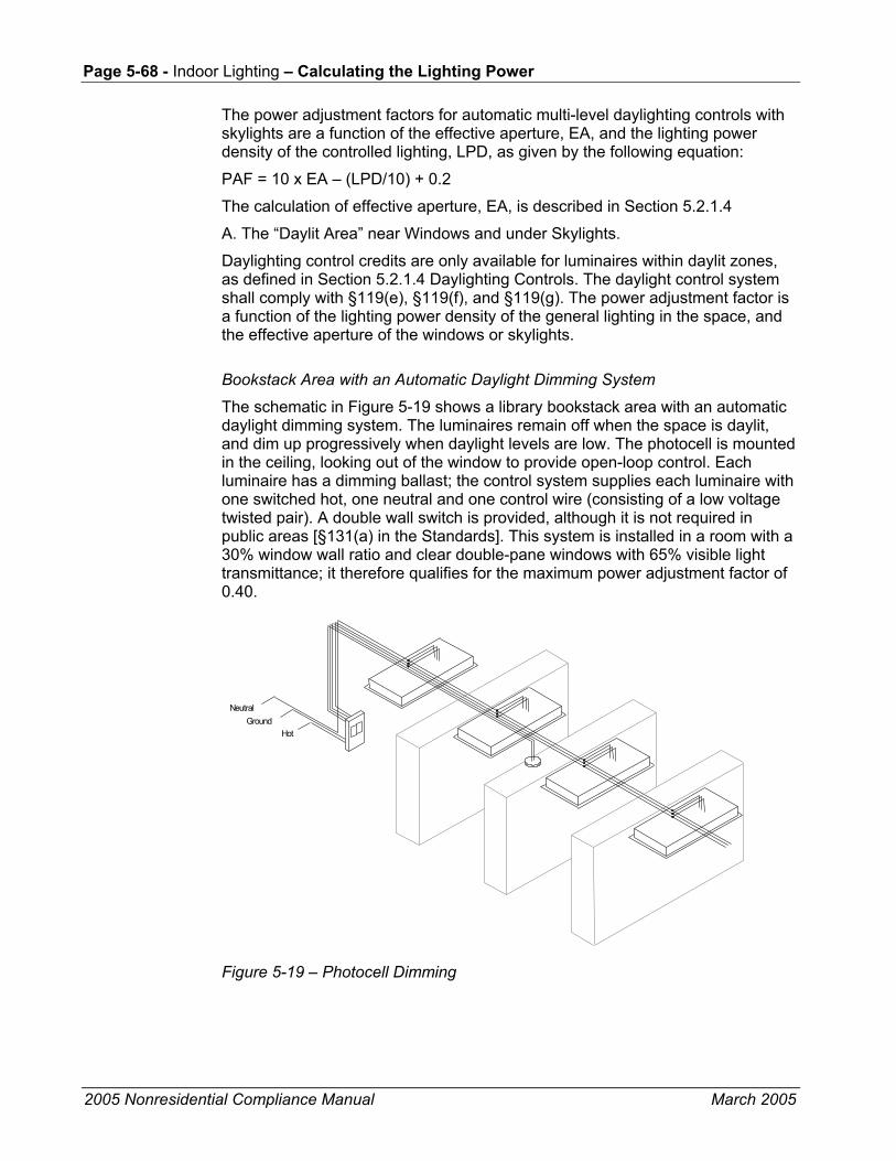
Page 5-68 - Indoor Lighting – Calculating the Lighting Power
2005 Nonresidential Compliance Manual March 2005
The power adjustment factors for automatic multi-level daylighting controls with skylights are a function of the effective aperture, EA, and the lighting power density of the controlled lighting, LPD, as given by the following equation:
PAF = 10 x EA – (LPD/10) + 0.2
The calculation of effective aperture, EA, is described in Section 5.2.1.4
A. The “Daylit Area” near Windows and under Skylights.
Daylighting control credits are only available for luminaires within daylit zones, as defined in Section 5.2.1.4 Daylighting Controls. The daylight control system shall comply with §119(e), §119(f), and §119(g). The power adjustment factor is a function of the lighting power density of the general lighting in the space, and the effective aperture of the windows or skylights.
Bookstack Area with an Automatic Daylight Dimming System
The schematic in Figure 5-19 shows a library bookstack area with an automatic daylight dimming system. The luminaires remain off when the space is daylit, and dim up progressively when daylight levels are low. The photocell is mounted in the ceiling, looking out of the window to provide open-loop control. Each luminaire has a dimming ballast; the control system supplies each luminaire with one switched hot, one neutral and one control wire (consisting of a low voltage twisted pair). A double wall switch is provided, although it is not required in public areas [§131(a) in the Standards]. This system is installed in a room with a 30% window wall ratio and clear double-pane windows with 65% visible light transmittance; it therefore qualifies for the maximum power adjustment factor of 0.40.
Hot Ground
Neutral
Figure 5-19 – Photocell Dimming
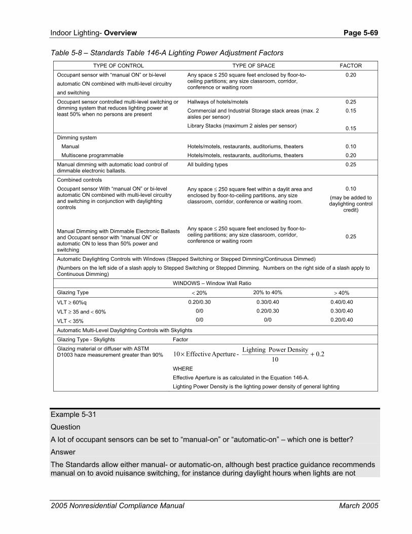
Indoor Lighting- Overview Page 5-69
2005 Nonresidential Compliance Manual March 2005
Table 5-8 – Standards Table 146-A Lighting Power Adjustment Factors
TYPE OF CONTROL TYPE OF SPACE FACTOR
Occupant sensor with “manual ON” or bi-level automatic ON combined with multi-level circuitry and switching
Any space ≤ 250 square feet enclosed by floor-to-ceiling partitions; any size classroom, corridor, conference or waiting room
0.20
Occupant sensor controlled multi-level switching or dimming system that reduces lighting power at least 50% when no persons are present
Hallways of hotels/motels Commercial and Industrial Storage stack areas (max. 2 aisles per sensor) Library Stacks (maximum 2 aisles per sensor)
0.25 0.15
0.15
Dimming system Manual Multiscene programmable
Hotels/motels, restaurants, auditoriums, theaters Hotels/motels, restaurants, auditoriums, theaters
0.10 0.20
Manual dimming with automatic load control of dimmable electronic ballasts.
All building types 0.25
Combined controls Occupant sensor With “manual ON” or bi-level automatic ON combined with multi-level circuitry and switching in conjunction with daylighting controls Manual Dimming with Dimmable Electronic Ballasts and Occupant sensor with “manual ON” or automatic ON to less than 50% power and switching
Any space ≤ 250 square feet within a daylit area and enclosed by floor-to-ceiling partitions, any size classroom, corridor, conference or waiting room.
Any space ≤ 250 square feet enclosed by floor-to-ceiling partitions; any size classroom, corridor, conference or waiting room
0.10
(may be added to daylighting control
credit)
0.25
Automatic Daylighting Controls with Windows (Stepped Switching or Stepped Dimming/Continuous Dimmed) (Numbers on the left side of a slash apply to Stepped Switching or Stepped Dimming. Numbers on the right side of a slash apply to Continuous Dimming)
WINDOWS – Window Wall Ratio
Glazing Type < 20% 20% to 40% > 40%
VLT ≥ 60%q
VLT ≥ 35 and < 60%
VLT < 35%
0.20/0.30 0/0 0/0
0.30/0.40 0.20/0.30
0/0
0.40/0.40 0.30/0.40 0.20/0.40
Automatic Multi-Level Daylighting Controls with Skylights
Glazing Type - Skylights Factor
Glazing material or diffuser with ASTM D1003 haze measurement greater than 90% 2.0
10DensityPower Lighting - Aperture Effective 10 +×
WHERE Effective Aperture is as calculated in the Equation 146-A. Lighting Power Density is the lighting power density of general lighting
Example 5-31
Question
A lot of occupant sensors can be set to “manual-on” or “automatic-on” – which one is better?
Answer
The Standards allow either manual- or automatic-on, although best practice guidance recommends manual on to avoid nuisance switching, for instance during daylight hours when lights are not

Page 5-70 - Indoor Lighting – Calculating the Lighting Power
2005 Nonresidential Compliance Manual March 2005
required, or when someone enters a room only briefly, or when someone passes the open doorway of a room with an occupant sensor. Manual-on also maximizes energy savings. Automatic-on may offer added convenience in storerooms, restrooms and similar spaces.
Example 5-32
Question
A multi-scene programmable controller is used to control display lighting in a store. Can a power adjustment factor be applied?
Answer
The 0.2 power adjustment factor for multiscene programmable controllers is only available for the general lighting of hotels/motels, restaurants, auditoriums and theaters. However, special lighting power allowances are available for retail display lighting under the tailored compliance method.
Example 5-33
Question
Can I provide multi-level control with occupant sensors just by wiring an occupant sensor in series with a wall switch? Will such a combination qualify for a power adjustment factor?
Answer
This arrangement will meet the mandatory requirements for multi-level control in §131(b) and automatic shut-off control in §131(d). But this configuration does not qualify for a power adjustment factor credit because if one leaves the room with all of the lights on, the next time the lights are turned on, all the lights will be on. Special circuitry is required. Many control system manufacturers offer products specifically for bi-level occupant sensing systems, many of which use a double wall switch with an occupant sensor integrated into the switch faceplate, or an integrated power pack that supplies an occupant sensor in the ceiling. See Section 5.4.4 Non-qualifying Circuit for Occupancy Sensor Credit Example.
Example 5-34
Question
Where can I find guidance on how to commission lighting controls? I need information on where to position sensors, how to set time delays and how to get the best performance from my system.
Answer
Many manufacturers provide comprehensive guidance on the design and commissioning of systems; this guidance is often tailored to the characteristics of their own products and is therefore the best advice available. More general information can be obtained from best practices guidance such as The Advanced Lighting Guidelines which can be downloaded free of charge at http://www.newbuildings.org, or from the Lighting Controls Association website http://www.aboutlightingcontrols.org.

Indoor Lighting- Overview Page 5-71
2005 Nonresidential Compliance Manual March 2005
5.5 Theme Parks Specialty lighting within theme parks are exempt from the lighting power density calculations. However, all other lighting must comply with the Standards. The Standards must be enforced for primary function areas that are included in Standards Table 146-C. The primary function areas in theme parks must be quantified in Title 24 lighting documentation, and are not exempt from the lighting power density requirements. These include, retail, restrooms, restaurants, lobbies, ballrooms, theaters and other primary function areas in theme parks. The treatment of these primary function areas is no different for theme parks than for other building projects. However, the lighting that is used strictly for entertainment in theme parks, such as the entertainment production lighting related only to presenting the theme of the theme park, may be exempted from Title 24 lighting power density compliance. An example of a theme park may be a large amusement park, which includes carnival rides, shows, and exhibits.
5.6 Exit Way and Egress Lighting Lighting that is required for exit signs subject to the California Building Code and has an input power rating of five watts per illuminated face or less, and exit way or egress illumination that is normally off and that is subject to the California Building Code, is exempt from lighting power calculations. Exit way and egress lighting systems are regulated by Article 700 of the State Electricity Code (Title 24, Part 3), which specifies that:
• Emergency systems are those systems legally required and classed as emergency by municipal, state, federal, other codes, or by any governmental agency having jurisdiction.
• These systems are intended to automatically provide illumination to designated areas in the event of failure of normal power supply.
• These systems must be separately switched from the general lighting systems.
• These systems shall be so arranged that only authorized persons have control of the emergency lighting.
• These systems have an emergency power supply independent of the general lighting power supply, or are equipped with two or more separate and complete systems with independent power supply, each system providing sufficient current for emergency lighting purposes.
Note that §131(a) in the Standards, the area controls of the mandatory measures, specifies that lighting in areas within a building that must be continuously illuminated for reasons of building security or emergency egress are exempt from the switching requirements of the area controls of the mandatory measures for a maximum of 0.5 w/ft2. These lights must be installed in areas designated as security or emergency egress areas on the plans, and must be controlled by switches accessible only to authorized personnel. The

Page 5-72 - Indoor Lighting – Historic Buildings
2005 Nonresidential Compliance Manual March 2005
remaining lighting in the area, however, is still subject to the area switching requirements.
When applying lighting power adjustment factors to luminaires in a space, exit way, emergency, and egress lighting systems that are on a separate circuit and are not controlled by a qualifying control device, are not eligible for these credits.
5.7 Historic Buildings Exception 1 to §100(a) states that qualified historic buildings, as defined in the California Historical Building Code (Title 24, Part 8 or California Building Code, Title 24, Part 2, Volume I, Chapter 34, Division II) are not covered by the Standards. However, non-historical components of the buildings, such as new or replacement mechanical, plumbing, and electrical (including lighting) equipment, additions and alterations to historic buildings, and new appliances in historic buildings may need to comply with Building Energy Efficiency Standards and Appliance Standards, as well as other codes. For more information about energy compliance requirements for Historic Buildings, see Section 1.7.1, Building Types Covered, in Chapter 1, the Overview of this manual.
5.8 Signs The sign energy requirements in §148 apply to all internally illuminated (cabinet) and externally illuminated signs, whether they are used indoors or outdoors. Examples include, but are not limited to, internally illuminated and externally illuminated signs in theaters, convention centers, and lobbies. These requirements do not apply to unfiltered signs (see definitions in Joint Appendix I) or exit signs. The power consumed by signs regulated by §148 is not included total building lighting power budget for compliance purposes. Detailed requirements for sign compliance are discussed in Chapter 6 of this manual, Outdoor Lighting and Signs.
5.9 Common Lighting Systems This section describes a simplified application of the area category method that can be used for compliance. This method can only be used for area category method function areas for which the lighting power densities are 1.0 watts per square foot and higher. This easy method allows 1.0 W/ft² or less for installing common lighting systems like those described in Table 5-9. Designing systems to these specifications will result in a system that uses less than 1.0 W/ft².
One type of Luminaire: Luminaires must consist of any one type of luminaire, plus exit signs, installed as described in Table 5-9. Spacing measurements are taken from the plan view center of the luminaire. Luminaires must be mounted at least 1/3 of the indicated mounting distance away from any ceiling-high partition.
More than One Type of Luminaire: If there is more than one type of luminaire (excluding exit signs) located within one space enclosed with ceiling high

Indoor Lighting- Overview Page 5-73
2005 Nonresidential Compliance Manual March 2005
partitions, the spacing between different luminaires shall be the larger of the required spacing for the two luminaires in Table 5-9.
This method is cannot be used if any of the following luminaire types exists in the building:
• Luminaires employing Edison base line voltage sockets.
• Luminaires exceeding 75 W designed for low voltage lamps, incandescent or halogen.
• Track lighting systems or other flexible lighting systems which allows the addition or relocation of luminaires without altering the wiring of the system of any kind or voltage.
• Line voltage monopoints permitting the installation of track luminaires.
Normally off emergency lighting systems required by code and not used except under a power outage or in emergency conditions are not included in power allowance computations.
Up to 5% of the total luminaires of the project (by count) may be hardwired luminaires of any type (except track lighting, which is not appropriate) rated not more than 150 W.
For compact fluorescent luminaires with permanently installed ballasts that are capable of operating a range of lamp wattages, the highest operating input wattage of the rated lamp/ballast combination must be use for determining the luminaire wattage.
For luminaires with modular components that allow conversion between screw-based and pin-based sockets without changing the luminaire housing or wiring, it shall be assumed that an incandescent lamp of the maximum relamping wattage available for that system will be used.
Permanent Lighting: A complete and permanent lighting system must be installed. Additional lighting, such as lighting within furniture systems, shall not be installed in the space. Undercabinet luminaires are allowed, however, when attached to the underside of modular furniture overhead cabinets, bins or shelves and complying with the requirements for undercabinet luminaires in Table 5-9.
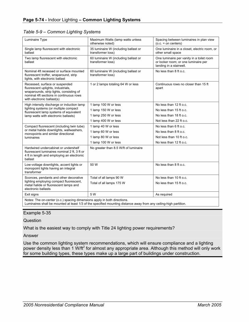
Page 5-74 - Indoor Lighting – Common Lighting Systems
2005 Nonresidential Compliance Manual March 2005
Table 5-9 – Common Lighting Systems
Luminaire Type Maximum Watts (lamp watts unless otherwise noted)
Spacing between luminaires in plan view (o.c. = on centers)
Single lamp fluorescent with electronic ballast
35 luminaire W (including ballast or transformer loss)
One luminaire in a closet, electric room, or other small space
Two lamp fluorescent with electronic ballast
60 luminaire W (including ballast or transformer loss)
One luminaire per vanity in a toilet room or locker room; or one luminaire per landing in a stairwell.
Nominal 4ft recessed or surface mounted fluorescent troffer, wraparound, strip lights, with electronic ballast
60 luminaire W (including ballast or transformer loss)
No less than 8 ft o.c.
Recessed, surface or suspended fluorescent uplights, industrials, wraparounds, strip lights, consisting of nominal 4ft sections in continuous rows with electronic ballast(s)
1 or 2 lamps totaling 64 W or less Continuous rows no closer than 15 ft apart
High intensity discharge or induction lamp lighting systems (or multiple compact fluorescent lamp systems of equivalent lamp watts with electronic ballasts)
1 lamp 100 W or less 1 lamp 150 W or less 1 lamp 250 W or less 1 lamp 400 W or less
No less than 12 ft o.c. No less than 15 ft o.c. No less than 18 ft o.c. Not less than 22 ft o.c.
Compact fluorescent (including twin tube) or metal halide downlights, wallwashers, monopoints and similar directional luminaires
1 lamp 40 W or less 1 lamp 60 W or less 1 lamp 80 W or less 1 lamp 100 W or less
No less than 6 ft o.c. No less than 8 ft o.c. Not less than 10 ft o.c. No less than 12 ft o.c.
Hardwired undercabinet or undershelf fluorescent luminaires nominal 2 ft, 3 ft or 4 ft in length and employing an electronic ballast
No greater than 8.5 W/ft of luminaire
Low-voltage downlights, accent lights or monopoint lights having an integral transformer
50 W No less than 8 ft o.c.
Sconces, pendants and other decorative lighting employing compact fluorescent, metal halide or fluorescent lamps and electronic ballasts
Total of all lamps 90 W Total of all lamps 175 W
No less than 10 ft o.c. No less than 15 ft o.c.
Exit signs 5 W As required
Notes: The on-center (o.c.) spacing dimensions apply in both directions. Luminaires shall be mounted at least 1/3 of the specified mounting distance away from any ceiling-high partition.
Example 5-35
Question
What is the easiest way to comply with Title 24 lighting power requirements?
Answer
Use the common lighting system recommendations, which will ensure compliance and a lighting power density less than 1 W/ft2 for almost any appropriate area. Although this method will only work for some building types, these types make up a large part of buildings under construction.

Indoor Lighting- Overview Page 5-75
2005 Nonresidential Compliance Manual March 2005
5.10 Simplification for Tenant Spaces As an option, an entire tenant space can use the Complete Building Method when at least 82% of the permitted space is one of the primary functions listed in Standards Table 146-C (see Figure 5-20 and Examples 5-30 through 5-32).
A tenant space is part of a building leased or used by a single tenant that is separated from other tenants by demising partition(s).
Figure 5-20 – Lighting Power Density Calculation Flowchart For Simplified Tenant Spaces
• Lighting compliance can also be achieved using the Tailored Method or the Performance Method. The lighting power portion of the Performance allowed budgets is determined by selecting the appropriate Complete Building or Area Category uses or function types, in accordance with the modeling rules shown in the flowchart above. The Tailored method may also be used to establish the lighting portion of the Performance Method allowed budget.
• A tenant space is a part of the building leased or used by a single entity that is separated by demising partitions from other tenants. The Complete Building Method may not be used for permits issued for partial tenant spaces. Multiple tenant spaces, when making up less than an entire building but permitted together, may each use the Complete Building Method by showing that EACH space meets the requirements of the Complete Building Method.
• PFA = Primary Function Area. All Primary Function Areas are listed in Standards Table 146-C. The "dominant" PFA refers to the Function Area with the largest floor area among all Function Areas contained within a tenant space.

Page 5-76 - Indoor Lighting – Simplification for Tenant Spaces
2005 Nonresidential Compliance Manual March 2005
• Type of Use (TOU) is defined as a single type of use, as used in this Manual and listed in Standards Table 146-B. To determine the AREA of the TOU, the following areas shall be included, provided they serve the primary use function: Lobbies, Corridors, and Restrooms.
• When using the Area Category Method, breakout separate Function areas into separate area categories, such as Retail Function, Corridor, Restroom, and Commercial Storage Functions.
Example 5-36
Question
If the figure below is a new building, what is the allowed lighting power for the entire building?
Mech. Common
Room Restrooms
BankCorridors
Grocery
Store
Drawing not to scale
Retail Area
Restrooms
Cor
ridor
s
Corridor
Function Area %of Area Non-Retail: Bank (Financial Transactions) 4,000 28% Grocery Store 3,500 24% Mechanical Room 200 1% Common Restrooms 300 2% Common Corridors 1,000 7% Total Non-Retail 9,000 62% Retail: Retail Area 4,700 32% Retail Restrooms 200 1% Retail Corridors 600 4% Total Retail 5,500 38% Total Building 14,500 100%

Indoor Lighting- Overview Page 5-77
2005 Nonresidential Compliance Manual March 2005
Procedure
Using the flowchart in Figure 5-20:
1. Is the lighting compliance for an entire building? Yes.
2. Does the building have one of the types of uses that makes up 90% of the floor area of the building? No (the largest type of use category is Retail which occupies 38% of the floor area of the entire building).
Calculate the allowed lighting power by the area category method.
Area Category Method:
Function Area W/ft2 Watts Bank (Financial Transactions) 4,000 1.2 4,800 Grocery Store 3,500 1.6 5,600 Mechanical Room 200 0.7 140 Common Restrooms 300 0.6 180 Common Corridors 1,000 0.6 600 Retail Function 4,700 1.7 7,990 Retail Restrooms 200 0.6 120 Retail Corridor 600 0.6 360 Total Building Lighting Power 19,790 W
Answer
The allowed lighting power is 19,790 W.
Example 5-37
Question
If the figure in the example above is an existing building and the retail store is being renovated, what is the allowed lighting power for the retail store?
Procedure
Using the flowchart in Figure 5-20:
1. Is the lighting compliance for an entire building? No.
2. Is the lighting compliance for an entire tenant space? Yes.
3. Is there a single PFA that dominates at least 90% of the entire tenant space floor area (at least 70%/single tenant for retail spaces)? Yes. The permit is for one tenant (retail store), and the retail function area is greater than 70% of the entire retail store (4,700/5,500 = 0.855).
4. Does the dominant PFA match with one of the primary types of uses shown in Table 146-B in the Standards? Yes.
Calculate the allowed lighting power by either the complete building method, or the area category method.
Complete Building Method:
Allowed lighting power is 5,500 x 1.5 = 8,250 W.
Area Category Method:
Function Area W/ft2 Watts A) Retail 4,700 1.7 7,990

Page 5-78 - Indoor Lighting – Simplification for Tenant Spaces
2005 Nonresidential Compliance Manual March 2005
B) Restrooms 200 0.6 120 C) Retail Corridor 600 0.6 360 Total Allowed Lighting Power 8,470W
Answer
The allowed lighting power is 8,250 W using the complete building method and 8,470 W using the area category method.
Example 5-38
Question
What is the allowed lighting power for the Retail Grocery store combination in the figure below?
Restrooms
CorridorOffice
Retail/Grocery
Drawing not to scale
Function Area % of Area Retail 5,750 63% Grocery 2,150 23% Retail Office 450 5% Restrooms 300 3% Corridors 550 6% Total 9,200 100%
Answer
Procedure
Using the flowchart in Figure 5-20:
1. Is the lighting compliance for an entire building? Yes.
2. Does the building have one of the types of uses that makes up 90% of the floor area of the building (at least 70%/single tenant for retail)? No. (There are several Primary Function Areas including retail, grocery, office, restroom and storage. However, the office function is a separate tenant and therefore excluded from the Complete Building Method.)
Calculate the allowed lighting power by the area category method.
Function Area W/ft2 Watts Retail 5,750 1.7 9,775 Grocery 2,150 1.6 3,440 Office 450 1.2 540 Restrooms 300 0.6 180

Indoor Lighting- Overview Page 5-79
2005 Nonresidential Compliance Manual March 2005
Corridor 550 0.6 330 Total Allowed Lighting Power 14,265 W
The allowed lighting power is 14,265 W.
5.11 Minimum Skylight For Large Enclosed Spaces Minimum Skylight Area for Large Enclosed Spaces is discussed in [§143 (c)] applies to low-rise conditioned or unconditioned enclosed spaces that meet the following conditions:
• Greater than 25,000 ft2
• Directly under a roof
• Ceiling heights greater than 15 feet
• A lighting power density for general lighting equal to or greater than 0.5 w/ft2
At least half of the floor area must be daylit under skylights. Minimum Skylight Area is defined in Table 143-F.
Additional discussions about Minimum Skylight Area can be found in Chapter 3 of the Manual, Building Envelope (Section 3.2.4 Skylights in Large Enclosed Spaces), and this chapter in Section 5.13.2, Prescriptive Measures, Additions, Lighting Systems Installed for the First Time. Discussions about requirements for Effective Aperture, Skylight Characteristics, and Controls can be found in Section 5.2.1.4, Daylighting Controls.
Though Section 143(c) requires that at least half of the floor space be daylit and that the ratio of skylight area to daylit area be 3%, there are maximum skylight area requirements whenever the skylights are above conditioned spaces. Section 43(a) 6 limits skylight area to 5% of the gross roof area in most cases and to 10% of the roof area for atria over 55 feet. The thermal transmittance (U-factor) and solar heat gain (SHGC) of skylights are also limited to the appropriate climate zone specific values in Tables 143(a-c). In general these requirements require the use of double glazed skylights. See Section 3.2.4 Skylights in Large Enclosed Spaces of this manual for more details of skylight area and skylight properties requirements. When the skylights are above unconditioned spaces there is no limitation placed on skylight area or its U-factor or SHGC. In such cases, single glazed skylights will comply with the code requirements as long as they are sufficiently diffusing [i.e. the glazing or diffuser material has a haze rating greater 90% as defined in §143(c)]. Products that have such a rating include prismatic diffusers, laminated glass with diffusing interlayers, pigmented plastics etc. The purpose of this requirement is to assure the light is diffused over all sun angles.
Other methods of diffusion that result in sufficient diffusion of light over the course of the entire year would also be acceptable in lieu of using diffusing glazing. Acceptable alternatives are baffles or reflecting surfaces that ensure over all sun angles encountered during the course of a year that direct beam light is reflected off of a diffuse surface prior to entering the space. This

Page 5-80 - Indoor Lighting – Acceptance Requirements
2005 Nonresidential Compliance Manual March 2005
alternative method of diffusion would have to be documented by the designer and approved by the code authority in your jurisdiction.
5.12 Acceptance Requirements Acceptance tests are used to verify that lighting controls were installed and calibrated correctly. These tests require that a responsible party certify that controls are installed and calibrated properly. This responsible party is typically the contractor who installed the lighting controls. To verify that they are calibrated properly, the responsible party must conduct a test and make modifications to the control until it passes the test. The test results must be recorded on acceptance test forms and are part of the building documentation. These forms must be filled out before the building authority grants a certificate of occupancy.
The Standards have acceptance test requirements for:
• Manual daylighting controls
• Automatic daylighting controls.
• Occupancy sensors.
• Automatic time-switch controls.
A detailed description of each acceptance test can be found in Chapter 8 of this manual, Acceptance Requirements.
5.13 High Efficacy Luminaires High efficacy luminaires are defined by §150(k) for residential buildings. However, high efficacy luminaires that are installed in nonresidential buildings must also meet the definition of §150(k) for high efficacy. These luminaires must meet the following requirements:
• Ballasts for lamps rated 13 watts or greater shall be electronic and shall have an output frequency no less than 20 kHz.
• Luminaires shall not contain medium screw base sockets
EXCEPTION: Outdoor high intensity discharge (HID) luminaires with HID rated medium screw base sockets and factory-installed hardwired HID ballast which meet the minimum lumens per watt in Table 150-C. HID Ballasts for this application may be electromagnetic (magnetic).
• Luminaires must contain only lamps with the following minimum efficacies

Indoor Lighting- Overview Page 5-81
2005 Nonresidential Compliance Manual March 2005
Table 5-10 – Standards Table 150-C
Lamp Power Rating Minimum Lamp Efficacy
15 watts or less 40 lumens per watt
Over 15 watts to 40 watts 50 lumens per watt
Over 40 watts 60 lumens per watt
To determine minimum lamp efficacy category only the watts of the lamp (not the ballast) are to be considered.
5.14 Additions and Alterations §149
New additions must meet the all mandatory measures for both the prescriptive and performance method of compliance. Prescriptive requirements, including the lighting power densities must be met if prescriptive method of compliance is used. If performance approach is used, the lighting power densities may be traded-off against other prescriptive building features.
Altered lighting components must also meet applicable mandatory measures described below. Prescriptive requirements apply if in a permitted space (The Basis for the Alteration Area is discussed in Section 5.12.3, Prescriptive Measure – Alterations below) more than 50% of the fixtures are replaced, or if the connected lighting load is increased. These requirements are discussed in the following sections.
Lighting alterations generally refers to replacing the entire luminaire, which includes the housing, lamps, ballasts, and louvers or lenses. Simply replacing the lamps and ballasts in an existing fixture is not considered a lighting alteration. Replacing or installing new wiring that connects the luminaires to switches, relays, branch circuits, and other control devices represents a lighting alteration and therefore must meet the applicable mandatory requirements as described below.
5.14.1 Mandatory Measures – Additions and Alterations
New additions and lighting systems that are installed for the first time in an existing space must comply with mandatory requirements of §119, §130, §131, and §132.
All “altered” lighting components in alterations must comply with applicable mandatory requirements of §119, §130, §131, and §132. Although these mandatory requirements apply only to altered lighting components, it is recommended that mandatory measures be considered for the entire space to achieve maximum energy savings.
Compliance requirements vary with the details and extent of the alterations. The mandatory requirements include certification of any new lamps and ballasts that are installed if they are the type regulated by the Appliance Efficiency Regulations. Any new lighting controls must meet minimum performance

Page 5-82 - Indoor Lighting – Additions and Alterations
2005 Nonresidential Compliance Manual March 2005
requirements. In addition, control and circuiting requirements apply to the altered lighting components as follows:
• Independent switching within a space or room is required if ceiling height partitions are installed or moved, creating a new enclosed space.
• Multi-level lighting controls requirements apply if the alteration consists of rewiring, and any individual enclosed space within the altered area exceeds 100 ft2, has more than 0.8 w/ft2, and has more than one luminaire [§131 (b)] (corridor lighting is exempt from this alteration requirement).
• Separate switching for daylit areas is required if the alteration involves rewiring, and any individual enclosed space within the altered area exceeds 250 ft2. See §131 (c).
• Alterations in spaces with existing skylights must comply with the daylit area mandatory requirements of §131 (c).
• All altered luminaires in a space must meet the automatic shut-off controls requirements of §131 (d).
• Altered display lighting systems that involve rewiring must meet the requirements of §131 (e).
For lighting alterations purposes, rewiring refers to replacement or installation of new wires that serve the circuit between the switches, relays, branch circuits, other control devices, and rewired luminaire(s). In the case where only the wiring in a circuit that connects the switch and the luminaire(s) is being replaced without any alterations to the luminaire(s), the wiring system itself is considered the altered component and must therefore meet the lighting control requirements.
For more information on mandatory requirements, see Sections 5.1 Overview, 5.2 Lighting Design Procedure, Lighting Equipment Certification, and Daylighting Control.
5.14.2 Prescriptive Measures – Additions
All additions must comply with the prescriptive requirements of
• §143 (c) – Minimum Skylight Area for Large Enclosed Spaces in Low-rise Buildings, and
• §146 – Prescriptive Requirements for Indoor Lighting
Additions must also meet the mandatory requirements discussed in Section 5.12.1 above. For more information on these requirements, refer to Section 5.2.2 Prescriptive Approach.
5.14.3 Prescriptive Measures – Alterations
Alterations that involve the following must comply with §146:
• Replacing more than 50% of the luminaires, or

Indoor Lighting- Overview Page 5-83
2005 Nonresidential Compliance Manual March 2005
• An increase in the connected lighting load.
When it is necessary to calculate the existing wattage to demonstrate that the alteration does not result in an increased lighting level, use the same methodology used for new lighting installations found in this chapter.
The Basis for the Alteration Area Only those areas of the building enclosed by floor-to-ceiling partitions in which lighting fixtures are being replaced or the connected lighting load is being increased, need to meet lighting requirements of the Standards. Areas of the building enclosed by floor-to-ceiling partitions in which no lighting is being altered do not need to meet lighting requirements of the Standards. The basis for determining if more than 50% of fixtures are being replaced is the permitted space (not the building space), excluding any enclosed areas that are not receiving new light fixtures. Enclosed areas are areas that are surrounded by permanent floor-to-ceiling partitions. For alterations, the permitted space is usually not an entire building, and may not be an entire tenant space. Building departments will often define "permitted space" to include only those areas where alterations are proposed.
Lighting Systems Installed for the First Time Spaces with lighting systems that are installed for the first time must comply with the applicable prescriptive requirements of §143 (c) and §146. “Installed for the first time” refers to when the first lighting permit has been issued for a lighting system in a given space. This means skylights will be required in all large open spaces (greater than 25,000 ft2) with ceiling heights greater than 15 feet, where a lighting system is being installed for the first time even if the building shell was constructed without any skylights, or with minimal lights. For example: If the building shell is built with a minimal lighting system for exit, egress, and emergency and later a general lighting system is installed in the building, all lighting other than the exit, egress, and emergency lighting is considered a lighting system installed for the first time for the purposes of the §143 (c) of the Standards.
If it is likely that the building will ultimately be finished as a big box retail space, warehouse, exhibition hall etc. where a room can be larger than 25,000 ft2 and with ceiling heights greater than 15 feet, it is recommended to consider skylights and skylight controls as an integral part of the design and construction phase of the building shell, early in the design process. If skylights are impractical, the performance approach may be used to show overall compliance for the entire building by installing other energy savings features that save as much energy as skylights with multi-level astronomical time switch control of lighting.
Note that alterations must also meet the mandatory requirements discussed in Section 5.12.1 above.

Page 5-84 - Indoor Lighting – Additions and Alterations
2005 Nonresidential Compliance Manual March 2005
Example 5-39
Question
There are 30 lighting fixtures in an existing office space. We are replacing five fixtures without increasing the connected lighting load or rewiring any of fixtures. Which Standards requirements must we comply with?
Answer
All altered lighting components must meet the mandatory measures of §119, §130 and §131. However, since the luminaires are not being rewired, only independent room switching controls, daylit area under skylight controls (if applicable), and the automatic shut-off control requirements apply, if the luminaires are not already controlled by these devices.
Since less than 50% of the luminaires are being replaced without increasing the connected lighting load, no prescriptive requirements apply to this space.
Example 5-40
Question
If in the example above, the five replaced luminaries are also being rewired, then which Standards requirement must be complied with?
Answer
In addition to the mandatory measures that are discussed in the example above, the luminaires must also meet the requirements for multi-level controls, daylit area controls (if applicable), and display lighting controls, if the luminaires are not already controlled by these devices. As in the example above, there are no prescriptive requirements that apply to this space.
Example 5-41
Question
If in the example above, 20 fixtures were being replaced, then which Standards requirements must be complied with?
Answer
Since more than 50% of the fixtures are being replaced, in addition to all the mandatory requirements discussed above, all prescriptive requirements of §146 must also be complied with.
Example 5-42
Question
There are 10 luminaires on the same circuit controlled by a single switch. Two of these luminaires are being replaced without rewiring. How would the automatic shut-off control requirement apply to these luminaires?

Indoor Lighting- Overview Page 5-85
2005 Nonresidential Compliance Manual March 2005
Answer
All altered (or replaced)) luminaires must comply with the automatic shut-off control requirements regardless of rewiring. Since the two altered luminaires are on the same circuit as the remaining eight unaltered luminaires, the simplest and most energy efficient option is to apply the automatic shut-off control device to all 10 luminaires that are on the same circuit. An automatic shut-off control may be a programmable time clock, a light swiping device, an occupant sensor, or any other device capable of turning off the light automatically. A second choice may be to isolate and apply to control device only to the two altered luminaires.
Example 5-43
Question
All light fixtures are being replaced in one enclosed room of a commercial tenant space. The entire tenant space currently has a total of 25 light fixtures. The altered room will receive a total of eight new light fixtures. How much lighting power is allowed for the new lighting?
Answer
Since all lighting fixtures within the enclosed area (room) are being replaced, then more than 50% of the lighting in the applicable space (the enclosed room) is new. Therefore, the lighting power in this space must meet the requirements for new construction.
Example5-44
Question
All light fixtures in one enclosed room of a commercial tenant space are being replaced. The permitted space however, covers the entire tenant space due to a proposed replacement HVAC system. How much lighting power is allowed for the new lighting?
Answer
Though the entire tenant space is the permitted space, only the room where new lighting is proposed is evaluated for determining whether more than 50% of the light fixtures are new. In this case, 100% of the lighting in this room is being altered, so the lighting power in this room must meet the requirements for new construction.
Example 5-45
Question
All light fixtures in a men's clothing department are being replaced. The men’s clothing department covers one-third of main open sales floor of the department store. The permit space covers only the men’s clothing department floor area. How much lighting power is allowed for the new lighting?
Answer
Although the men’s clothing department covers only one-third of the entire enclosed floor area, it still constitutes 100% of the permitted space. Only this area should be considered for the basis of determining if more than 50% of fixtures are being replaced. In this case, 100% of the lighting in area is being altered, so the lighting power in this area must meet the requirements for new construction.

Page 5-86 - Indoor Lighting – Additions and Alterations
2005 Nonresidential Compliance Manual March 2005
Example 5-46
Question
In a 30,000 sf unconditioned warehouse, a 10,000 sf portion is supposed to be converted into an office space, with 1 w/sf for lighting with 16 foot ceilings. Do skylights have to be installed in the office portion of the building?
Answer
No. The portion of the buildings with lighting power density of 1 W/sf is less than 25,000 sf, so there will be no requirements for skylights.
Example 5-47
Question
In the example above, 26,000 sf of the area is converted into 26 office areas of 1,000 sf each. Do skylights have to be installed in the office portion of the building?
Answer
No. §143 (c) the Standards require skylights in “enclosed spaces that are greater than 25,000 sf…”. In this example since each enclosed area is only 1,000 sf, there will be no skylight requirements.
Example 5-48
Question
A 30,000 sf building has a 16,000 sf area with an 18-foot high ceiling and another 14,000 sf area with 13-foot high ceiling. The lighting power density in this building is 1 w/sf. Do skylights have to be installed in the portion of the building with 18-foot ceiling?
Answer
No. §143 (c) of the Standards require skylights in “enclosed spaces that are greater than 25,000 sf directly under a roof with ceiling height greater than 15 ft…”. In this example the area with ceiling of greater than 15 foot is only 16,000 sf, therefore there are no skylight requirements.
Example 5-49
Question
If in the example above the area under the 18-foot ceiling is 26,000 sf and the area under the 13-foot ceiling is 4,000 sf, must skylights be installed in the 26,000 sf portion of the building.
Answer
Yes. The 26,000 sf portion of the building meets all three criteria for skylights specified in §143 (c); 1) the enclosed area is greater than 25,000 sf, 2) the ceiling height for the whole area is greater than 15-foot, and 3) the lighting power density exceeds 0.5 w/sf.
Example 5-50
Question
A 30,000 sf speculative building shell with a 30 foot ceiling height is built.
A minimal lighting system is installed for exit lighting resulting in a lighting power density of 0.1 w/sf. No general lighting has been installed. Are skylights required?

Indoor Lighting- Overview Page 5-87
2005 Nonresidential Compliance Manual March 2005
Answer
No. Since the LPD is less that 0.5 W/sf, skylights are not required even though the other criteria of Section 143(c) are met (a low rise open space greater than 25,000 sf and ceiling heights greater than 15 feet).
Example 5-51
Question
In the example above, the space is sold to a big box retailer who is going to add a 1.5 W/sf general lighting system but no suspended ceiling so that the building will retain 30 foot ceiling heights. Will skylights be required for the tenant finish?
Answer
Yes, skylights are prescriptively required. Section 149(b)1F says that when lighting systems are installed for the first time, the lighting system must comply with the requirements of new lighting systems and the building must meet the skylighting requirements of section 143(c). Thus speculative buildings designed for the warehouse or big box retail market will be more salable with skylights pre-installed.
Example 5-52
Question
A pre-existing air-conditioned 30,000 sf warehouse with 30 foot ceiling and no skylights will have its general lighting system replaced as part of a conversion to a big box retail store. Are skylights prescriptively required?
Answer
No. The general lighting system is being replaced and is not “installed for the first time.” Thus Section 149(b)1F does not apply and therefore does not trigger the requirements in Section 143(c) for skylighting.
Example 5-53
Question
A pre-existing unconditioned 30,000 sf warehouse with 30 foot ceiling and no skylights has a 1.5 W/sf lighting power density and will have air conditioning added as part of a conversion to a big box retail store. Are skylights prescriptively required?
Answer
Yes. Since the space is defined as “newly conditioned,” all of the requirements of Section 149 (a) apply to the space. This includes the prescriptive skylighting requirements in Section 143(c) when there is an enclosed space larger than 25,000 sf, with a ceiling height greater than 15 feet and a lighting power density greater than 0.5 w/sf.
5.15 Lighting Plan Check Documents At the time a building permit application is submitted to the building department, the applicant also submits plans and energy compliance documentation. This section describes the recommended forms and procedures for documenting compliance with the lighting requirements of the Standards. It does not describe

Page 5-88 - Indoor Lighting – Lighting Plan Check Documents
2005 Nonresidential Compliance Manual September 2005
the details of the requirements. The following discussion is addressed to the designer preparing construction and compliance documents, and to the building department plan checkers who are examining those documents for compliance with the Standards.
The use of each form is briefly described below, and complete instructions for each form are presented in the following subsections. These forms may be included in the lighting equipment schedules on the plans, provided the information is in a similar format as the suggested form. • LTG-1-C: Certificate of Compliance:
This form is required for every job, and it is required to appear on the plans. • LTG-2-C: Indoor Lighting Schedule:
This form is required for all submittals. • LTG-3-C: Portable Lighting Worksheet:
This form is required for all submittals. • LTG-4-C: Lighting Controls Credit Worksheet:
This form should only be required when calculating control credit watts. See Standards Table 146-A for lighting control credits.
• LTG-5-C: Indoor Lighting Power Allowance Worksheet: This form is required when calculating the Lighting Power Allowance using the Complete Building, Area Category, or Tailored Method for compliance.
• LTG-6-C: Tailored Method Worksheet: This form should only be required when calculating the Lighting Power Allowance using the Tailored Method.
• LTG-7-C: Room Cavity Ratio Worksheet: This form should only be required when using the Tailored Method. The Room Cavity Ratio is required in the Tailored Method Worksheet.
• LTG-8-C: Common Lighting Systems Method: This form is only used when showing compliance using the Common Lighting Systems Method.
• LTG-9-C: LINE VOLTAGE TRACK LIGHTING WORKSHEET: This form is only used when line voltage track lighting is used.
• OLTG-4-C: Worksheet for Signs: See instructions for OLTG-4-C, Sign Worksheet in Chapter 6, Outdoor Lighting and Signs Chapter.
5.15.1 LTG-1-C: Certificate of Compliance
The LTG-1-C Certificate of Compliance form is in three parts. All parts must appear on the plans (usually near the front of the electrical drawings). A copy of these forms should also be submitted to the building department along with the rest of the compliance submittal at the time of building permit application. With building department approval, the applicant may use alternative formats of these forms (rather than the official Energy Commission forms), provided the information is the same and in a similar format.
LTG-1-C, Part 1 of 4 and 2 of 4 are required for all submittals. LTG-1-C, Part 3 of 4 submittal is only required if control credits are claimed.

Indoor Lighting- Overview Page 5-89
2005 Nonresidential Compliance Manual March 2005
LTG-1-C Part 1 of 4
Project Description 1. PROJECT NAME is the title of the project, as shown on the plans and
known to the building department. 2. DATE is the date of preparation of the compliance submittal package. It
should be on or after the date of the plans, and on or before the date of the building permit application.
3. PROJECT ADDRESS is the address of the project as shown on the plans and as known to the building department.
4. PRINCIPAL DESIGNER - LIGHTING is the person responsible for the preparation of the lighting plans, one of two people who sign the STATEMENT OF COMPLIANCE (see below). The person’s telephone number is given to facilitate response to any questions that arise.
5. DOCUMENTATION AUTHOR is the person who prepared the energy compliance documentation. This may or may not be the principal designer (it may be a person specializing in energy standards compliance work). This person is not subject to the Business and Profession’s Code. The person’s telephone number is given to facilitate response to any questions that arise.
6. ENFORCEMENT AGENCY USE is reserved for building department record keeping purposes.
General Information 1. DATE OF PLANS is the last revision date of the plans. If the plans are
revised after this date, it may be necessary to resubmit the compliance documentation to reflect the altered design. The building department will determine whether or not the revisions require this.
2. BUILDING CONDITIONED FLOOR AREA has specific meaning under the Standards. Refer to Joint Appendix I for a discussion of this definition.
3. The number entered here should match the floor area entered on form ENV-1-CC-05.
4. CLIMATE ZONE of the building. Refer to Joint Appendix I. 5. BUILDING TYPE is specified because there are special requirements for
high-rise residential and hotel/motel guest room occupancies. All other occupancies that fall under the Nonresidential Standards are designated “Nonresidential” here. It is possible for a building to include more than one building type. See §149 in the Standards for the formal definitions of these occupancies.
6. CONDITIONED SPACE is a space that is directly or indirectly air-conditioned. Check this box if the building includes conditioned spaces where lighting systems are being installed. Tradeoffs are not allowed between conditioned and unconditioned spaces.
7. UNCONDITIONED SPACE is a space that is not directly or indirectly air-conditioned. Check this box if the building includes unconditioned spaces where lighting systems are being installed. Tradeoffs are not allowed between conditioned and unconditioned spaces.

Page 5-90 - Indoor Lighting – Lighting Plan Check Documents
2005 Nonresidential Compliance Manual March 2005
8. INDOOR AND OUTDOOR SIGNS are internally illuminated signs that are located either indoor or outdoor. If these signs are present, the Form OLTG-4-C must be filled out along with either LTG-1-C or OLTG-1-C.
9. PHASE OF CONSTRUCTION indicates the status of the building project described in the documents. Refer to Joint Appendix I for detailed definitions.
• NEW CONSTRUCTION should be checked for all new buildings, newly conditioned space (see §149 in the Standards) or for new construction in existing buildings (tenant improvements, see Section 1.7.10) that are submitted for envelope compliance.
• ADDITION should be checked for an addition which is not treated as a stand-alone building, but which uses Option 2 described in §149 in the Standards.
• ALTERATION should be checked for alterations to existing building lighting systems. See Section 5.13.
• METHOD OF COMPLIANCE indicates which method is being used and documented with this submittal:
• PERFORMANCE should be checked when the performance method is used to show compliance. All required performance documentation must be included in the plan check submittal when this method is used.
• COMPLETE BUILDING should be checked if the lighting system complies using the complete building method, as documented on the LTG-2-C Form
• AREA CATEGORY should be checked if the lighting system complies using the area category method, as documented on the LTG-2-C form
• TAILORED should be checked if the tailored method of lighting compliance, with supporting documentation (LTG-6-CC-05 and LTG-7-C) is submitted.
• COMMON LIGHTING should be checked if the common lighting method of lighting compliance, with supporting documentation (LTG-8-C) is submitted.
Lighting Mandatory Measures
This portion requests the location of notes clarifying the inclusion of the mandatory requirements. Notes should be included on the plans to demonstrate compliance with mandatory requirements of the Standards.
Following are prototype examples of the notes that should be rewritten to actual conditions. A note for each of the items listed should be included, even if the note states “not applicable”.

Indoor Lighting- Overview Page 5-91
2005 Nonresidential Compliance Manual March 2005
Building Lighting Shut-off The building lighting shut-off system consists of an automatic time switch, with a zone for each floor: or the building is separately metered and exempt from the shut-off requirement.
Override for Building Lighting Shut-off The automatic building shut-off system is provided with a manual accessible override switch in sight of the lights. The area of override is not to exceed 5,000 square feet.
Automatic Control Devices Certified All automatic control devices specified are certified; all alternate equipment shall be certified and installed as directed by the manufacturer.
Fluorescent Ballast and Luminaires Certified All fluorescent fixtures subject to certification and specified for the projects are certified.
Individual Room/Area Controls Each room and area in this building is equipped with a separate switch or occupancy sensor device for each area with floor-to-ceiling walls.
Uniform Reduction for Individual Rooms All rooms and areas greater than 100 square feet and more than 0.8 watts per square foot of lighting load shall be controlled with Multi-level switching for uniform reduction of lighting within the room.
Daylit Area Control All rooms that are greater than 250 square feet and contain windows and skylights, that allow for the effective use of daylight in the area shall have 50% of the lighting power in each daylit area controlled by a separate switch; or
The effective use of daylight throughout cannot be accomplished because the windows are continuously shaded by a building on the adjacent lot. Diagram of shading during different times of year is included on plans.
The above notes are only examples of wording. Each mandatory measure that requires a separate note should be listed on the plans.
To verify certification, use one of the following options:
The Energy Hotline (1-800-772-3300) can verify certification of appliances not found in the above directories.
• The Energy Commission’s Web Site includes listings of energy efficient appliances for several appliance types. The web site address is http://www.energy.ca.gov/efficiency/appliances/.
• The complete appliance databases can be downloaded from the California Energy Commission’s Internet FTP site

Page 5-92 - Indoor Lighting – Lighting Plan Check Documents
2005 Nonresidential Compliance Manual September 2005
(ftp://sna.com/pub/users/efftech/appliances). This requires database software (spreadsheet programs cannot handle some of the larger files). To use the data, a user must download the database file (or files), download a brand file and a manufacturer file and then decompress these files. Then download a description file that provides details on what is contained in each of the data fields. With these files, and using database software, the data can be sorted and manipulated.
Documenting the mandatory measures on the plans is accomplished through a confirmation statement, notes and actual equipment location as identified on the plans. The plans should clearly indicate the location and type of all mandatory control devices; such as manual switches, reduced level control, daylit area, controls, building shut-off and overrides, and exterior light controls.
Lighting Worksheet
Check the appropriate boxes to indicate which worksheet(s) are being included with the certificate of compliance.
LTG-1-C Part 2 of 4 Part 2 of LTG-1-C is used to indicate compliance by showing that the installed indoor lighting power is lower than the lighting power allowance.
Installed Indoor Lighting Power for Conditioned and Unconditioned Spaces:
• Indicate the installed lighting for conditioned spaces from form LTG-2-C
• Indicate installed lighting power from LTG-2-C, portable lighting from LTG-2-C, and any lighting controls credits from LTG-4-C. Sum to determine total installed lighting power.
• Indicate lighting control credit for conditioned spaces form LTG-4-C
• Indicate the conditioned space adjusted installed lighting power
• Indicate the installed lighting for unconditioned spaces from LTG-2-C
• Indicate lighting control credit for unconditioned spaces from LTG-4-C
• Indicate the unconditioned space adjusted installed lighting power
Allowed Indoor Lighting Power
• Indicate which method of compliance is being used and indicate the total allowance from the corresponding worksheet.
Alternate Compliance
• Check the appropriate box if the performance or area category method is being used for compliance.

Indoor Lighting- Overview Page 5-93
2005 Nonresidential Compliance Manual September 2005
• Indicate the allowed indoor lighting power for unconditioned spaces from LTG-5-C
Mandatory Lighting Measures for Indoor Lighting and Daylit Areas
The Mandatory Automatic Controls portion is where those devices that meet the mandatory control requirements are listed, that would include devices for building shut-off, individual room control and control of exterior lights.
1. CONTROL LOCATION lists the location(s), room number(s), area number(s), or description of the controls and should match the plans.
2. CONTROL IDENTIFICATION lists the symbol of the control and should match the plans.
3. CONTROL TYPE lists the type of certified control device used to meet the mandatory automatic control requirement, such as automatic time switch, dimming, photosensor, etc.
4. SPACE CONTROLLED lists the location of controlled lights.
Check the box(s) if the controls are used for daylighting.
Notes to Field -This space is for use by the building department plans examiner to alert the field inspector to look for important inspection items.
Typical controls may be covered by general notation.
LTG-1-C Part 3 of 4
LTG-1-C, Part 3 of 4 submittal is only required if control credits are claimed. Controls for Credit in Conditioned and Unconditioned Spaces
The Controls for Credit portion is similar to the Mandatory Automatic Controls portion. The only difference is in the last column, LUMINAIRES CONTROLLED.
1. CONTROL LOCATION lists the location(s) or room number(s) of the controls and should match the plans.
2. CONTROL IDENTIFICATION lists the symbol of the control and should match the plans.
3. CONTROL TYPE lists the type of certified control device used to meet the automatic control requirement. Such controls are, occupant, daylight, dimming sensors etc.
4. LUMINAIRES CONTROLLED should list the luminaire type and quantity controlled for credit.
5. TYPE should use the same name as on the plans.
6. # OF LUMINAIRES should indicate the number of luminaires of that type that are controlled by the control type. A general plan notation on the plans may cover all typical controls.

Page 5-94 - Indoor Lighting – Lighting Plan Check Documents
2005 Nonresidential Compliance Manual September 2005
This space is for use by the building department plans examiner to alert the field inspector to look for important inspection items.
LTG-1-C Part 4 of 4 Acceptance Requirements
The Designer is required to check the box for each type of lighting system in the building when an acceptance test is required. Below each box that is checked the Designer is required to list the equipment that must be tested and the number of systems to be tested in parentheses. The Designer should think abut who will be conducting the tests and list this person in the section titled “Test Performed By”. Those who are allowed to conduct the tests are the installing contractor, design professional or an agent selected by the owner.
Statement of Compliance
The Statement of Compliance is signed by the person responsible for preparation of the plans for the building. This person is also responsible for the energy compliance documentation, even if the actual work is delegated to someone else (the Documentation Author described above). It is necessary that the compliance documentation be consistent with the plans. The Business and Professions Code governs who is qualified to prepare plans, and therefore to sign this statement; check the appropriate box that describes the signer’s eligibility.
Applicable sections from the Business and Professions Code (based on the edition in effect as of August 2000), referenced on the Certificate of Compliance, are provided below.
5.15.2 LTG-2-C: Indoor Lighting Schedule
LTG-2-C, Part 1 of 2, is used to describe the lighting fixtures and control devices designed to be installed in the building. The Installed Lighting Power for Conditioned Spaces is calculated by completing this form.
1. LUMINAIRE NAMES shall be listed by name or symbol. 2. DESCRIPTION should indicate a short list of the technical features. 3. LAMP TYPE is the type of lamps such as T-8, T-5, high output (HO), etc. 4. NUMBER OF LAMPS PER LUMINAIRE is the number of lamps per
luminaire. 5. WATTS PER LAMP is watts per lamp including ballast losses and ballast
factor. This is not the nominal lamp wattage published by the manufacturer.
6. NUMBER OF BALLASTS PER LUMINAIRE is the number of ballasts per each luminaire.
7. WATTS PER LUMINAIRE is the total watts per luminaire including lamps, ballasts, and all loses and ballast factors. This number is equal to WATTS PER LAMPS multiplied by NUMBER OF LAMPS PER LUMINAIRE.
8. If CEC DEFAULT is checked, this indicates the wattage is a standard value from the data in ACM Manual Appendix NB. If this column is not

Indoor Lighting- Overview Page 5-95
2005 Nonresidential Compliance Manual March 2005
checked, nonstandard values must be substantiated with manufacturer’s data sheets.
9. NUMBER OF LUMINAIRES is the number of similar luminaires in the space.
10. INSTALLED WATTS is total installed watts for similar luminaire installed in the space, which is the product of WATTS PER LUMINAIRE and NUMBER OF LUMINAIRES.
Subtotal the total watts for each luminaire, add portable lighting watts, if any from Ltg-3-C, and subtract the control credits, if any, from form LTG-4-C. The results are the actual lighting power (adjusted) for conditioned spaces of the building. This total cannot be greater than the lighting power allowance calculated below.
LTG-2-C, Part 2 of 2, is used to describe the lighting fixtures and control devices designed to be installed in the building. The Installed Lighting Power for Unconditioned Spaces is calculated by completing this form.
The instructions for filling LTG-2-C, Part 2 of 2 are similar to instructions LTG-2-C, Part 2 of 1 described above, except this form is to be used for unconditioned spaces.
5.15.3 LTG-3-C: Portable Lighting Worksheet
LTG-3-C should be used to identify and account for all portable lighting fixtures in office areas in buildings, both planned and unplanned. Note that this applies to all office spaces with planned portable lighting systems regardless of the primary function area of the building and does not apply to enclosed (floor-to-ceiling permanent partition) office spaces with floor areas less than 250 ft2. Use Table 1 for unspecified portable lighting systems. Most buildings with typical open office type of layouts should use this approach. Use Table 2 if the specific portable lighting systems to be installed in the office space are known and documented on the plans. The documentation must include specific features of the portable lighting, and identify the specific task areas that each portable lighting equipment will illuminate. Use Table 3 if no portable lighting fixtures are planned for the office space(s) and if detailed documentation of the lighting levels by overhead lighting are provided to show that they meet the lighting requirements of that space.
If lighting system documentation shows less than 0.2 W/ft2 of portable lighting, the designer must demonstrate that the lighting design meets lighting needs without additional portable lighting. This must be demonstrated by a detailed point calculation method analysis using a lighting simulation tool. Average illuminance calculations are not acceptable for determining that a lighting system meets lighting requirements of the space. All assumptions used in the simulation model of the lighting design must be submitted as an attachment to Form LTG-3-C. This documentation must include information on luminaire layout (accompanied by furniture layout including modular furniture walls, shelves and cabinets), location, brand, model, and performance characteristics of all luminaires in the space. In addition, the documentation must include the coefficient of utilization (CU) for the luminaires, luminaire spacing, surface reflectance, ballast factors, lamp lumens, various loss factors, and all lighting
Page 5-96 - Indoor Lighting – Lighting Plan Check Documents
2005 Nonresidential Compliance Manual March 2005
design calculations. The resultant minimum-to-maximum or minimum-to-average ratios (typically generated by lighting simulation tools) must also be included in the submittal. The designer is responsible for providing all of the information that the building inspector may need to clearly understand that less than 0.2 W/ft2 of portable lighting will be needed, including describing the Design Intent (based on IESNA recommended design criteria) and including the target illumination ratios for comparison to the proposed lighting design.
Table 1 Portable Lighting not Shown on Plans 1. ROOM # OR ZONE ID - Enter the name of the room number or zone ID
for space(s) that have more than 250 square feet of floor area B. The DEFAULT lighting power density for this space is 0.2 w/ft2.
2. DEFAULT – 0.2 w/ft2 is the default lighting power density for portable lighting.
3. AREA (ft2) – Enter room or zone office area for the floor area of the space identified in COLUMN A.
4. TOTAL WATTS (B x C) – Enter the total watts for each room or zone by multiplying the values in COLUMNS B and C.
5. COLUMN TOTALS – Sum the values in each of COLUMNS C and D and enter the result in the boxes at the bottom of Table 1A.
Table 2 Detailed Lighting Design - Portable Lighting Shown on Plans 1. ROOM # OR ZONE ID – Enter the name of the room number or zone ID
for the space(s) that contains the task area(s) for which specific portable lighting system(s) and associated task areas have been shown on the plans. Use a separate line for each task area.
2. PORTABLE LIGHTING DESCRIPTION(S) PER TASK AREA – Enter the type of lamp and fixture used for portable task lighting to illuminate each task area and include a detailed lighting design demonstrating how the lighting design meets the illumination needs throughout the space. Note that supporting documents include output forms from lighting software and drawings that clearly show the location, brand, model, and performance characteristics of all luminaires in the space. In addition, all properties of the space that effect lighting performance (like surface reflectance and furniture layout) must be clearly summarized on documentation attached to Form LTG-1-C Part 3 of 3. The information needs to be traceable to specific types of portable lighting products that will be installed.
3. LUMINAIRE(S) WATTS PER TASK AREA – Enter the total number of watts for all portable lighting used to illuminate each task area.
4. TASK AREA (ft2) is the surface area in the space that will be served by the portable light. This may not be the same as the actual partition-to-partition area of the cubicle. It may be limited to the actual area served by the task lighting, or be limited to the desk area in the cubicle. There may be more than one task area in each ROOM # OR ZONE ID identified in COLUMN A. Each task area must be identified on the plans in a fashion that can be matched to the list of portable lighting.
5. NUMBER OF TASK AREAS – Enter the number of task areas in column D for each room or zone identified in COLUMN A.
6. TOTAL AREA (ft2) [D x E] – Enter the results of COLUMN D multiplied times COLUMN E.

Indoor Lighting- Overview Page 5-97
2005 Nonresidential Compliance Manual March 2005
7. TOTAL WATTS (C x E) – Enter the results of COLUMN C multiplied times COLUMN E.
8. COLUMN TOTALS – Sum up the values in each of COLUMNS F and G and enter the result in the boxes at the bottom of Table 2.
9. ROOM # OR ZONE ID – Enter the name of the room number or zone ID for space(s) for which no portable lighting is required (as established by supporting documents and drawings). Note that supporting documents include output forms from lighting software and drawings that clearly show the location, brand, model, and performance characteristics of all luminaires in the space. In addition, all properties of the space that effect lighting performance (like surface reflectance and furniture layout) must be clearly summarized on documentation attached to Form LTG-3-C.
10. TOTAL AREA (ft2) – Enter the areas of the spaces listed in A.
Building Summary – Portable Lighting
• TOTAL AREA (ft2) – Enter the sum of the total areas from Tables 1, 2, and 3.
• TOTAL WATTS - Enter the total watts of portable lighting from Tables 1 and 2. This number is entered on forms LTG-1-C under portable lighting.
5.15.4 LTG-4-C: Lighting Controls Credit Worksheet
1. LTG-4-C, Part 1 of 2, is used to report the control credits for conditioned spaces. When certain types of automatic lighting controls listed in Table 146-A in the Standards are used, a credit is permitted. This table also lists some restrictions that must be met in order to take credit for the controls.
• Lighting control credits are documented on form LTG-4-C. This requires a specific listing of each device that is used for credit and listing those luminaires controlled by that device.
• ROOM – List the room where the control device is controlling luminaires.
• DESCRIPTION – List a description of that device.
• PLANS – Indicate where on the plan set the controls are shown.
• ROOM AREA – Indicate the area of the room in which the controls are located.
• WWR – Indicate the window wall ratio for determining the daylighting control credit and described in the section on Effective Aperture. The window wall ratio for the window in the room should be used for vertical daylighting configurations.
• VLT – Indicate the visible light transmittance of the aperture. The visible light transmittance is discussed in the section on Visible Light Transmittance (VLT)

Page 5-98 - Indoor Lighting – Lighting Plan Check Documents
2005 Nonresidential Compliance Manual September 2005
2. SKYLIGHT EFFECT APERTURE – Show the skylight effective aperture as computed from Standards Equation 146-A (§146 in the Standards) for horizontal daylighting configurations.
3. WATTS OF CONTROL LIGHTING – The total watts of controlled lighting in each room.
4. ADJUSTMENT FACTOR – Indicate the power adjustment factor for that specific control device from Table 146-A in the Standards.
5. CONTROL CREDIT – The product of COLUMN G (Watts of Control Lighting) and COLUMN H (Lighting Adjustment Factor).
6. The total control credit watts (entered on LTG-4-C) is the sum of the control credit watts in COLUMN J. This credit is subtracted from the total installed watts to determine the actual lighting power (adjusted).
7. LTG-4-C, Part 2 of 2, is used to report the control credits for unconditioned spaces. The instructions for filling LTG-4-C, Part 2 of 2 are similar to LTG-4-C; Part 1 of 2 described above, except this form is to be used for unconditioned spaces.
5.15.5 LTG-5-C5: Indoor Lighting Power Allowance
Allowed Lighting Power The lighting power allowance is determined by calculating the maximum total watts of lighting that may be installed. There are four different methods that may be used. These methods may not be mixed in the same building permit application.
Complete Building Method This method may only be used when plans and specifications for the entire building are included in the permit application.
Area Category Method This method may be used when different primary function areas of a building are included in the permit application.
1. AREA CATEGORY is taken from Table 146-C in the Standards for the primary function of the area. If the building has a mixture of areas, each function area must be listed separately.
2. WATTS PER SF for that building type is taken from Standards Table 146-C and entered here.
3. AREA (SF) is the floor area of the primary function area, which is calculated by multiplying the width times the depth, as measured from the center of the interior bounding partitions. If the function area is bounded by exterior walls on one or more sides, the area is calculated by multiplying the width times the depth, as measured from the inside surface of the exterior walls to the center of the interior bounding partitions. If there are no partitions separating the boundary of the function areas on one or more sides, the boundary of the area is determined by a line separating the function areas where no bounding partitions exist.

Indoor Lighting- Overview Page 5-99
2005 Nonresidential Compliance Manual March 2005
4. ALLOWED WATTS is the product of the watts per square foot times the primary function area. This becomes the lighting power allowance for the area.
The sum of the lighting power allowance for each primary function area is the lighting power allowance for the building.
Tailored Method When the tailored method is used, the LTG-6-C form, or a similar form, must be included in the compliance submittal.
Unconditioned Spaces
This method may be used when different unconditioned areas complete building method type of uses and the area category method primary function areas of a building are included in the permit application.
1. AREA CATEGORY is taken from Table 146-C in the Standards for the primary function of the area. If the building has a mixture of areas, each function area must be listed separately.
2. WATTS PER SF for that building type is taken from Standards Table 146-C and entered here.
3. AREA (SF) is the floor area of the primary function area measured from the inside of bounding partitions (see the section B. Area Category Method).
4. ALLOWED WATTS is the product of the watts per square foot times the primary function area. This becomes the Lighting Power Allowance for the area.
The sum of the Lighting Power Allowance for each primary function area is the Lighting Power Allowance for the building.
Tailored Method - Unconditioned Spaces When the Tailored Method is used for unconditioned areas of the building, the LTG-6-C form, or a similar form, must be included in the compliance submittal.
5.15.6 LTG-6-C: Tailored Method Worksheet
The tailored method is the most detailed method of calculation for the lighting power allowance. The lighting power allowance is determined based on the individual needs of each task. This method is appropriate for buildings that have unusual lighting needs and in some cases, may increase the lighting power allowance to meet those needs. For a complete description of this method, refer to Section 5.2.2.1
C. Tailored Method.
If there are both conditioned and unconditioned spaces in a building and the tailored method is used to determine the allowed lighting power for both types of spaces, separate tailored method worksheets (LTG-6-C) must be filled out, one for conditioned spaces and one for unconditioned spaces. Each form must clearly indicate if it is used for conditioned or unconditioned spaces. Note that unconditioned spaces are all those areas that are not directly or indirectly

Page 5-100 - Indoor Lighting – Lighting Plan Check Documents
2005 Nonresidential Compliance Manual March 2005
conditioned. The conditioned and unconditioned allowances must be kept separated because when the performance method is used to show compliance for the entire building, the tailored LPD lighting for only the conditioned space must be entered for both the standards and proposed buildings. Inclusion of the unconditioned LPD would result in erroneous HVAC load calculations.
LTG-6-C: Part 1 of 3 This form should be submitted with all tailored method applications. It summarizes the results of the different parts of LTG-6-C, and includes the lighting power allowance calculations for illuminance categories A through G.
Tailored Method Summary 1. The ALLOWED WATTS is the summation for the building, included at the
top of Part 1 of form LTG-6-C. 2. LINE 1 is the BUILDING TOTAL ALLOWED WATTS for illuminance
categories A through G. This value is obtained from the bottom right corner of this form.
3. LINE 2 is the BUILDING TOTAL ALLOWED WATTS for display and ornamental/special effects lighting. This value is obtained from the total watts entries on LTG-6-C, Part 2, and Part 3. Each allotment is separately calculated and entered into the appropriate box on this form.
4. LINE 3 is the sum of lines 1, 2, and 3. The TOTAL ALLOWED WATTS is the lighting power allowance using the tailored method.
Tailored LPD- Illuminance
To complete the lower portion of Part 1 of this form, complete the following steps.
5. COLUMN A - lists the room number of space designation and should correspond with the plans.
6. COLUMN B - lists the task or activity that will occur in the room or space. If a space also contains a non-task area, this area should be entered on a separate line from the task area.
7. COLUMN C - lists the illuminance category for the room or space. This is determined by using the IES Handbook, Ninth Edition, 2000.
8. COLUMN D - lists the room cavity ratio (RCR) of each room or space. A RCR of less than 3.5 may be assumed for any room. Table 5-4 includes the RCR of simple spaces. The LTG-7-C form may be used to calculate an RCR greater than or equal to 3.5.
9. COLUMN E - lists the actual floor area of the room or space from the plans. The area is determined by measuring from the inside of the partitions that bound the task area.
10. COLUMN F - lists the lighting Power allowance density from Table 146-F in the Standards using the illuminance category (COLUMN C) and room cavity ratio (COLUMN D) for each room.
11. COLUMN G - is the product of the floor area times lighting power allowance density. The total for all rooms or spaces that contain task activities that fall within illuminance categories A through G is entered in line 1 at the top of LTG-6-C, Part 1.

Indoor Lighting- Overview Page 5-101
2005 Nonresidential Compliance Manual March 2005
LTG-6-C: Part 2 of 3
Display Lighting: Walls
When public areas include feature display lighting, it must be documented according to the display lighting procedure. To complete Part 2 of LTG-6-C, complete the following steps.
1. COLUMN A - lists the name of the task. 2. COLUMN B - lists the mounting height for display luminaires. Section
5.2.2.1 C.2. Specific Lighting Power Allowance contains a discussion on how to determine the mounting height.
3. COLUMN C - lists the mounting height adjustment factor for display luminaires. Select the proper factor from Standards Table 146-E and show in this column.
4. COLUMN D - lists the wall length of the display from the plans. This length must be totaled at the bottom of the column.
5. COLUMN E lists the lighting power allowance from Standards Table 146-D for wall display luminaires.
6. COLUMN F - is the product of the mounting height adjustment factor (COLUMN C) times the lighted display wall length (COLUMN D) times lighting power allowance density (COLUMN E).
7. COLUMN G - lists the luminaire name (consistent with LTG-1-C and LTG-2-C) that is illuminating the display. If more than one luminaire type is used to illuminate the display, each type must be listed separately. Multiple lines on this form may be used for this list.
8. COLUMN H - lists the quantity of luminaires used to illuminate the display. If track lighting is used, and the plans do not indicate the number of fixtures to be used on the track, the actual length of track is entered in this column.
9. COLUMN I - lists the total wattage of each luminaire type (including ballasts for fluorescent or high intensity discharge fixtures). For track and incandescent medium base socket fixtures, see Section 5.2.2.1 Allowed Lighting Power for how to determine the watts of these types of luminaires. If track lighting is used and the fixtures are not shown on the plans, enter 45 watts per foot of track in this column.
10. COLUMN J - is the product of the quantity of luminaires (COLUMN H) times the watts per luminaire (COLUMN I). If more than one luminaire type is used to illuminate the task or activity, the subtotal for all the luminaires illuminating the task should be indicated in this column on a separate line of the form.
11. COLUMN K - is the lesser of either the allotted watts (COLUMN F) or the design watts (COLUMN J).
12. The sum of the allowed watts in COLUMN K is entered on Line 2, Part 1 of LTG-6-C.
Display Lighting - Floors
When retail spaces include sales floor display lighting, the lighting must be documented according to the display lighting procedure established in the section above on Determining Allowed Watts.
Complete the upper portion of Part 3 of this LTG-6-C, using the following steps.

Page 5-102 - Indoor Lighting – Lighting Plan Check Documents
2005 Nonresidential Compliance Manual March 2005
1. COLUMN A - lists the name of the sales floor display. See the section above on Determining Allowed Watts for more information on the definition of Sales Floor Display Lighting.
2. COLUMN B - lists the mounting height of the display luminaires. Section 5.1.2.2 C.2. Specific Lighting Power Allowance contains a discussion on how to determine the mounting height of floor display luminaires.
3. COLUMN C - lists the mounting height adjustment factor for floor display luminaires, found in Table146-D in the Standards.
4. COLUMN D - lists the area of each space with floor displays from the plans. This area must be totaled at the bottom of the column.
5. COLUMN E - lists the Lighting Power Allowance density from Standards Table 146-D using the mounting height adjustment factors (COLUMNS C and D) for display luminaires. This allowance will always be based on illuminance category G.
6. COLUMN F - is the product of the mounting height adjustment factor (COLUMN C), the task area (COLUMN D) and the lighting power density (COLUMN E).
7. COLUMN G - lists the luminaire name (consistent with LTG-1-C and LTG-2-C) that is illuminating the display. If more than one luminaire type is used to illuminate the display, each type must be separately listed. Multiple lines on this form may be used for this list.
8. COLUMN H - lists the quantity of luminaires used to illuminate the display. If track lighting is used, and the plans do not indicate the number of fixtures to be used on the track, the actual length of the track is entered in this column.
9. COLUMN I - lists the total wattage of each luminaire type (including ballasts for fluorescent or high intensity discharge fixtures). For track and incandescent medium base socket fixtures, see the section above on Track Lighting for how to determine the watts of these types of luminaires. If track lighting is used, and the fixtures are not shown on the plans, enter 45 watts per foot of track in this column.
10. COLUMN J - is the product of the quantity of luminaires (COLUMN H) times the watts per luminaire (COLUMN I). If more than one luminaire type is used to illuminate the task or activity, the subtotal for all the luminaires illuminating the task should be indicated in this column on a separate line of the form.
11. COLUMN K - is the lesser of either the allotted watts (COLUMN F) or the design watts (COLUMN J).
12. The sum of the allowed watts for floor display lighting in COLUMN K is entered on Line 2, Part 1 of LTG-6-C.
LTG-6-C: Part 3 of 3 Ornamental and Special Effects Lighting includes chandeliers, sconces, lanterns, neon and cold cathode, light emitting diodes (LEDs), theatrical projectors, moving lights and light color panels (used decoratively, not as display lighting). If allowed in Standards Table 146-D column 5, use this form to compute the power allowance.
1. COLUMN A - lists the name of the luminaire or lighting type. 2. COLUMN B - lists area of the space that contains the chandelier or
special effects lighting.

Indoor Lighting- Overview Page 5-103
2005 Nonresidential Compliance Manual March 2005
3. COLUMN C - lists the lighting power allowance density from COLUMN 5 of Standards Table 146-D.
4. COLUMN D - is the product of the area (COLUMN B) and the lighting power density (COLUMN C).
5. COLUMN E - lists the luminaire name (consistent with LTG-1-C and LTG-2-C). Multiple lines on this form may be used to list multiple luminaires.
6. COLUMN F - lists the quantity of luminaires used for ornamental or special effects lighting. If track lighting is used, and the plans do not indicate the number of fixtures to be used on the track, the actual length of track is entered in this column.
7. COLUMN G - lists the total wattage of each luminaire type (including ballasts for fluorescent or high intensity discharge fixtures). For track, and incandescent medium base socket fixtures, see the section above on Track Lighting for how to determine the watts of these types of luminaires. If track lighting is used, and the fixtures are not shown on the plans, enter 45 Watts per foot of track in this column.
8. COLUMN H - is the product of the quantity of luminaires (COLUMN F) times the watts per luminaire (COLUMN G). If more than one luminaire type is used to illuminate the task or activity, the subtotal for all the luminaires illuminating the task should be indicated in this column on a separate line of the form.
9. COLUMN I - is the lesser of either the allotted watts (COLUMN D) or the design watts (COLUMN H).
The sum of the allowed watts for ornamental/special effects lighting in COLUMN I is entered on Line 2, Part 1 of LTG-6-C.
Very Valuable Merchandise Display Cases that contain jewelry and other valuable merchandise are Lighting Power Allowance for each square foot of lighted display case counter top, as shown in Table 146 D in the Standards. These displays may include jewelry, coins, fine china or crystal, precious stones, silver or other precious metal, small art objects and artifacts, or other valuable collections that require inspection of fine detail from outside a locked case.
1. COLUMN A - lists the name of the luminaire or location. 2. COLUMN B - lists area of the space. 3. COLUMN C - lists the Lighting Power Allowance density from Column 5
of Standards Table 146-D. 4. COLUMN D - is the product of the area (COLUMN B) and the lighting
power density (COLUMN C). 5. COLUMN E - lists area of the display case. 6. COLUMN F - is already listed and is 20 watts per square foot. 7. COLUMN G - is the product of the area (COLUMN E) and the lighting
power density (COLUMN F = 20 watts per square foot). 8. COLUMN H - lists the luminaire code (consistent with LTG-1-C and LTG-
2-C). Multiple lines on this form may be used to list multiple luminaires. 9. COLUMN I - lists the quantity of luminaires used for very valuable display
lighting. If track lighting is used, and the plans do not indicate the number of fixtures to be used on the track, the actual length of track is entered in this column.

Page 5-104 - Indoor Lighting – Lighting Plan Check Documents
2005 Nonresidential Compliance Manual March 2005
10. COLUMN J - lists the total wattage of each luminaire type (including ballasts for fluorescent or high intensity discharge fixtures). For track and incandescent medium base socket fixtures, see the section on Track Lighting for how to determine the watts of these types of luminaires. If track lighting is used, and the fixtures are not shown on the plans, 45 watts per foot of track is entered in this column.
11. COLUMN K - is the product of the quantity of luminaires (COLUMN I) times the watts per luminaire (COLUMN J). If more than one luminaire type is used to illuminate the task or activity, the subtotal for all the luminaires illuminating the task should be indicated in this column on a separate line of the form.
12. COLUMN L - is the lesser of either the allotted watts for the space area (COLUMN D), the allotted watts for the very valuable display area (Column G), or the design watts (COLUMN K).
The sum of the allowed watts for ornamental/special effects lighting in COLUMN L is entered on Line 2, Part 1 of LTG-6-C.
As with all applications in illuminance category G, the allowed lighting watts for feature displays may not exceed the actual installed wattage. This prevents unused display lighting allotments from being used in other areas of the store.
5.15.7 LTG-7-C: Room Cavity Ratio Worksheet (>3.5)
Form LTG-7-C is an optional form to be used only in conjunction with the Tailored Method and form LTG-6-C. LTG-7-C documents the calculation of room cavity ratios (RCRs) that are greater than or equal to 3.5 for spaces in illuminance categories A-G.
Rooms in a building which are relatively large generally have a high RCR. If the RCR is greater than or equal to 3.5, a higher LPD is allowed. If the RCR is less than 3.5, it does not need to be included on this form.
The form has two sections: Rectangular Spaces is for rooms with four 90° walls, and Non-rectangular Spaces is for all other room types (including oblique four walled and circular rooms).
Rectangular Spaces 1. COLUMN A - lists each room’s number, and should correspond to the
plans. 2. COLUMN B - lists the task/activity description for the room. If the room
has multiple tasks or activities, use the dominant activity for the room in this column.
3. COLUMN C - lists the length (L) of the room, measured in feet, from the interior surfaces of opposing walls. The length is typically the longest distance between two parallel walls in the room.
4. COLUMN D - lists the width (W) of the room, measured in feet, from the interior surfaces of opposing walls. The width is typically the smallest distance between two parallel walls in the room.
5. COLUMN E - lists the vertical distance, measured in feet, from the work plane to the center line of the lighting fixture. This measurement is called the room cavity height (H).

Indoor Lighting- Overview Page 5-105
2005 Nonresidential Compliance Manual March 2005
6. COLUMN F - is 5 times the product of the room cavity height H (from COLUMN E) and the sum of the room length and width (L from COLUMN C plus W from COLUMN D), all divided by the room area L (from COLUMN C) times room width (W from COLUMN D). This quantity is the RCR and should be entered in COLUMN D of Part 1 of LTG-6-C for tasks with illuminance categories A-G.
Non-rectangular Spaces
7. COLUMN A - lists each room’s number, and should correspond with the plans.
8. COLUMN B - lists the area or activity description for the room. If the room has multiple tasks or activities, use the dominant activity for the room in this column.
9. COLUMN C - lists the interior area (A) of the room in square feet. This should be determined by whatever means appropriate for the shape of the room.
10. COLUMN D - lists the room perimeter (P) measured in feet along the interior surfaces of the walls that define the boundaries of the room. For rooms with angled walls, this is the sum of the interior lengths of each wall in the room. For circular rooms, this is the interior radius of the room, squared, times pi (3.413).
11. COLUMN E - lists the vertical distance, measured in feet, from the work plane to the center line of the lighting fixture. This measurement is called the room cavity height (H).
12. COLUMN F - is 2.5 times the product of the room cavity height H (from COLUMN E) and room perimeter P (from COLUMN D), all divided by the room area A (from COLUMN C). This quantity is the RCR and should be entered in COLUMN D of Part 1 of LTG-6-C for tasks with illuminance categories A-G.
5.15.8 LTG-8-C: Common Lighting Systems Method Worksheet
Complete and submit form LTG-8-C (Common Lighting Systems) only if selecting the Common Lighting Systems method of allowed lighting power to determine if an indoor lighting system complies with the prescriptive requirements (§146 in the Standards). This method is only for building types shown in Standards Table 146-B, Area Category Method Lighting Power Density Values. In addition, the lighting power density listed in Standards Table 146-B for that building type must be at least 1.0 w/ft2.
1. SPACE NAME -- Insert the name or number of the space. Use a new row for each space in the building area.
2. SPACE AREA -- Insert the area (square feet) of the space.
3. LUMINAIRE TYPE OR CODE -- Insert the luminaire type, or the luminaire code shown in the luminaire schedule on the plans.
4. LUMINAIRE POWER -- Insert the power used by each luminaire of the type shown on this line, in watts. This is the total power including the ballast or transformer (or lamp, if no ballast or transformer is required to operate that lamp) when operating the lamp.

Page 5-106 - Indoor Lighting – Lighting Plan Check Documents
2005 Nonresidential Compliance Manual March 2005
5. Energy Commission DEFAULT -- Check the “Y” box if the luminaire power in the previous column is from Appendix NB in the Nonresidential ACM Manual, or check the “N” box if the power shown is from the ballast manufacturer’s literature. Include a copy of the ballast manufacturer’s specification sheet if that is the source for the luminaire power shown in the previous column.
6. LUMINAIRE SPACING OR LAYOUT -- Indicate the distance between luminaire centers in rows and columns, similar to the method used in column 3 of the Standards Table for common lighting systems.
5.15.9 LTG-9-C: Line Voltage Track Lighting Worksheet
LTG-9-C should be used to identify and account for all line voltage track lighting. (Line voltage track typically operates around 120 volts or greater). Completing this form and entering the results on LTG-2-C calculate the installed lighting power for line voltage track lighting.
To determine luminaire wattage incorporated into the installed lighting power for line voltage track lighting, use one of the two Methods described in 5.4.3 of the Nonresidential Manual.
Method 1 - Volt-Ampere (VA) Rating of the Branch Circuit(s) Feeding the Tracks or the Wattage of Integral Current Limiters
1. COLUMN A - list the name or number that identifies the branch circuit feeding the track. This column must be filled for all branch circuits feeding track lighting systems.
2. COLUMN B - list the volt-ampere rating of the branch circuit identified in column A. Fill out this column only when you are using the VA of the branch circuit to determine the wattage of the track(s). If integral current limiters are used to determine the wattage of the tracks, leave this column blank.
3. COLUMN C - Check the boxes to indicate if integral current limiters are used. Columns (C) thru (G) must only be filled out if the current limiter option is used to determine the wattages of all or some of the tracks connected to the branch circuit. These columns may be left blank if the branch circuit option is used to determine the wattage of the track(s)
4. COLUMN D – If the box(es) in column (C) is checked, list the wattage of the current limiter.
5. COLUMN E – List the length of the track. 6. COLUMN F – If the track is equipped with an integral current limiter,
multiply the value in column (E) by 15 watts per linear foot. If the track is not equipped with an integral current limiter, multiply the value in column (E) by 45 watts per linear foot.
7. COLUMN G – List the wattage of the track, which is the higher of columns (D) or (F)
8. SUB-TOTALS –Sub-totals are the sum of all track watts listed in column (G). If the branch circuit option is used to determine the wattage of the track(s), sub-total is the value listed in column (B).
9. TOTAL WATTS – Total watts are the sum of all sub-totals.

Indoor Lighting- Overview Page 5-107
2005 Nonresidential Compliance Manual March 2005
Method 2 - Use The Higher Of:
45 watts per linear foot of track, or the maximum relamping rated wattage of all luminaires.
1. COLUMN A - list the name or number that identifies the track lighting. 2. COLUMN B - list the linear feet of track lighting identified in column A 3. COLUMN C - is 45 watts per linear feet. This number is required for
using Method 2. 4. COLUMN D - Multiply the number in column B by the number in column
C. 5. COLUMN E - Determine the rated wattage of each luminaire (track head)
that will be installed on the line voltage track identified in column A according to §130 (c) of the Standards. Luminaire wattage for incandescent track heads shall be the maximum relamping rated wattage as listed on a permanent factory-installed label according to §130 (c) 1. Luminaire wattage for fluorescent and high intensity discharge (HID) track heads shall be the operating input wattage of the rated lamp/ballast combination according to §130 (c) 2. Luminaire wattage for low-voltage track heads (when mounted on line-voltage track) shall be the maximum rated wattage of the transformer on each track head according to §130 (c) 5. Add up the wattage for every luminaire that will be installed on the identified track and enter the total amount as the rated wattage.
6. COLUMN F - list the larger number from column D or column E. This is the installed lighting power for the track listed in column A. Add up all of the numbers in column F and list the total at the bottom. Enter this number in LTG-2-C for the installed lighting power of the track lighting systems determined by this method.
5.15.10 OLTG-4-C: Indoor Signs Worksheet
Complete and submit OLTG-4-C to show compliance for all indoor and outdoor signs. Refer to OLTG-4-C Worksheet and Plan Check Documents instructions in this manual’s Chapter 6, the Outdoor Lighting and Signs Chapter. For indoor and outdoor Signs, either LTG-1-C or OLTG-1-C Certificate of Compliance may be used in conjunction with OLTG-4-C.


Outdoor Lighting and Signs – Overview Page 6-1
2005 Nonresidential Compliance Manual September 2005
6. Outdoor Lighting and Signs
6.1 Overview The outdoor lighting and sign energy standards conserve energy, reduce winter peak electric demand, and are technically feasible and cost effective. They set minimum control requirements, maximum allowable power levels, minimum efficacy requirements, and require cutoff classification for large luminaires.
The lighting power allowances are based on current Illuminating Engineering Society of North America (IESNA) recommendations for the quantity and design parameters of illumination, current industry practices, and efficient sources and equipment that are readily available. Data indicates that the IESNA recommendations provide more than adequate illumination, since a 2002 baseline survey of current outdoor lighting practice in California suggests that the majority of establishments currently are illuminated at substantially lower levels than IESNA recommendations.11
Outdoor lighting and sign lighting are addressed in this chapter. Lighting in unconditioned buildings is addressed in Chapter 5.
The Standards do not allow tradeoffs between outdoor lighting power allowances and indoor lighting, HVAC, building envelope, or water heating (§147(a)).
V e n tila tio n 1 0 %
C o o lin g 1 6 %
H e a tin g 2 %
In d o o r L ig h tin g 3 3 %
O ff ice E q u ip m e n t 2 %
O u td o o r L ig h tin g 6 %
C o o k in g 1 %
R e fr ig e ra tio n 7 %
W a te r H e a tin g 1 %
M isce lla n e o u s 2 2 %
Figure 6-1 – Energy Consumption by End-Use
11 Integrated Energy Systems Productivity and Building Science, Outdoor Lighting
Baseline Assessment, New Buildings Institute, August 12, 2002

Page 6-2 - Outdoor Lighting and Signs – Overview
2005 Nonresidential Compliance Manual September 2005
6.1.1 History and Background
In response to the 2000 electricity crisis, the legislature charged the Energy Commission to develop outdoor lighting energy efficiency standards that are technologically feasible and cost-effective. . The intent of the legislature was that the Standards would provide ongoing reliability to the electricity system and reduce energy consumption.
Regulations for lighting have been on the books in California since 1977, but have only addressed indoor lighting through control requirements and maximum allowable lighting power. With the 2005 Standards the scope is expanded to include outdoor lighting applications as well as indoor applications in unconditioned buildings.
The 2005 Outdoor Lighting Standards evolved over a two-year period through a dynamic, open, public process. The Energy Commission encouraged all interested persons to participate in a series of public hearings and workshops through which the Energy Commission gathered information and viewed presentations on energy efficiency possibilities from a variety of perspectives. The Energy Commission hired a consulting team that included a number of nationally recognized outdoor lighting experts to assist in the development of the Standards. The Energy Commission also solicited ideas, proposals, and comments from a number of interested parties.
6.1.2 Scope and Application
Prior to 2005, the Standards only applied to indoor and outdoor lighting that was associated with conditioned buildings; that is buildings that are heated or cooled. The Standards now address lighting in unconditioned buildings (§146) as well as general site illumination and specific outdoor lighting applications (§147). The lighting applications that are addressed by the Standards are shown in the first two columns of Table 6-1. The first column is general site illumination applications, which allow for tradeoffs. The second column is specific outdoor lighting applications, each of which must comply on their own without tradeoffs. The lighting applications in the third column are not regulated (either controls or lighting power). The Standards include control requirements as well as limits on installed lighting power. The Standards also apply to internally illuminated and externally illuminated signs.
Tradeoffs Lighting tradeoffs are allowed between the lighting applications included in Standards Table 147-A General Illumination of the Site, which includes hardscape areas, building entrance without canopies, and outdoor sales lots.
The Standards do not allow tradeoffs between outdoor lighting power allowances and indoor lighting, HVAC, building envelope, or water heating [(§147(a)]. No tradeoffs are allowed between the specific lighting applications in Standards Table 147-B (so called use-it or lose-it allowances), or between the lighting applications included in Standards Table 147-B and Standards Table 147-A.

Outdoor Lighting and Signs – Overview Page 6-3
2005 Nonresidential Compliance Manual March 2005
Table 6-1 – Scope of the Outdoor Lighting Requirements
Lighting Applications Covered
General Site Illumination (tradeoffs permitted)
Specific Applications (tradeoffs not permitted)
Lighting Applications Not Regulated
Hardscape for automotive vehicular use, including parking lots, driveways and site roads Hardscape for pedestrian use, including plazas, sidewalks, walkways and bikeways Building entrances and facades Outdoor sales lots
Building facades Outdoor sales frontage Service stations canopies Vehicle service station hardscape Other sales canopies Non-sales canopies Ornamental lighting Drive-up windows Guarded facilities Outdoor dining
Temporary outdoor lighting Lighting required and regulated by the Federal Aviation Administratio and the Coast Guard Public right-of-way Lighting Lighting for sports and athletic fields, and children’s playgrounds Lighting for industrial sites Automated teller machine (ATM) lighting Lighting of public monuments Lighting used in or around swimming pools or water features Lighting of tunnels, bridges, stairs, and ramps Landscape lighting
Other outdoor lighting applications that are not included in Standards Tables 147-A, 147-B or 147-C are assumed to be not regulated by these Standards. This includes decorative gas lighting, lighting for theatrical purposes, including, stage, and film and video production, and emergency lighting powered by an emergency source as defined by the California electrical code
6.1.3 Summary of Requirements §119, §130, §132, §147 and §148
Mandatory Measures The Standards require that outdoor lighting be automatically controlled so that it is turned off during daytime hours and during other times when it is not needed. The mandatory measures also require that most of these controls be certified by the manufacturer and listed in the Energy Commission directories. Luminaires with lamps larger than 175 watts must be classified as cutoff so that the majority of the light is directed toward the ground. Luminaires with lamps larger than 60 watts must also be high efficacy or controlled by a motion sensor. More detail on the mandatory measures is provided in Section 6.2.
Lighting Power The 2005 Standards limit the lighting power for general site illumination and for specific outdoor lighting applications.
• General site illumination includes parking lots, driveways, walkways, building entrances, sales lots, and other paved areas of the site (see column one of Table 6-1). The Standards provide a separate allowance for each of these general site lighting applications, but tradeoffs are permitted among these applications. Essentially, one outdoor lighting budget can be calculated for all these general site applications together. Section 6.4 has more information on general site illumination.

Page 6-4 - Outdoor Lighting and Signs – Overview
2005 Nonresidential Compliance Manual March 2005
• Specific outdoor lighting applications include building facades, canopies, ornamental lighting, and the front row of car lots (outdoor sales frontage) [see column two of Table 6-1 for a complete list]). Trade-offs are not permitted for specific lighting applications. Each application must comply on its own. Section 6.5.3 has more information on specific lighting applications.
The allowable lighting power for both general site illumination and specific applications are based on four separate outdoor Lighting Zones. The Lighting Zones characterize ambient lighting in the surrounding areas. Sites with higher ambient lighting levels (Zones 3 or 4) have a larger allowance than sites with lower ambient lighting levels (Zones 1 or 2). Section 6.3 has more information on Lighting Zones.
Figure 6-2 – Outdoor Lighting Compliance Flowchart
Signs For signs, the Standards contain both prescriptive and performance approaches. Sign Standards apply to both indoor and outdoor signs. The prescriptive requirements specify that the signs shall be illuminated with efficient lighting sources (electronic ballasts, etc.) while the performance requirement specifies a maximum power expressed in W/ft² of sign area. Section 6.8 has more information about the requirements for signs.
Installed Power §130 (c)
The installed power for outdoor lighting applications shall be determined in accordance with §130 (c). Luminaire power for pin-based and high intensity

Outdoor Lighting and Signs – Mandatory Measures Page 6-5
2005 Nonresidential Compliance Manual September 2005
discharge lighting system types that are listed in ACM Manual Appendix NB may be used as an alternative to determine the wattage of outdoor luminaires. However, luminaires with screw-base sockets, and lighting systems which allow the addition or relocation of luminaires without altering the wiring of the system must be determined in accordance with §130 (c). Please see Chapter 5.4.3 of the Nonresidential Manual, Determining Luminaire Wattage, for additional discussion on installed power. Unlike indoor lighting, no power credits are offered for automatic controls. However, automatic controls are required by the mandatory measures.
6.2 Mandatory Measures The mandatory features and devices must be included in all outdoor lighting projects when they are applicable. These features have been proven to be cost-effective over a wide range of outdoor lighting applications. The mandatory measures require that the performance of certain equipment be certified by the manufacturers, that lighting systems have controls for efficient operation, that luminaires rated 100 watts or greater be high efficacy or be controlled by a motion sensor and that luminaires using lamps rated greater than 175 watts direct the majority of light toward the ground (cutoff type). Mandatory measures for outdoor lighting and signs are specified in §119, §130, and §132. These are similar to the mandatory measures for indoor lighting.
6.2.1 Certification §119
Manufacturers of certain lighting control products shall certify the performance of their products to the California Energy Commission. It is the responsibility of the designer, however, to specify products that meet these requirements. Code enforcement officials, in turn, check that the lighting controls specified are indeed certified.
The certification requirement applies to photo controls, astronomical time switches, and automatic controls. Many of these requirements are part of standard practice in California and should be well understood by those responsible for designing or installing lighting systems.
All automatic outdoor lighting control devices must be certified by the manufacturer before they can be installed in a building. The manufacturer must certify the devices to the Energy Commission. Once a device is certified, it is listed in the Directory of Automatic Lighting Control Devices. Call the Energy Hotline at 1-800-772-3300 to obtain more information.
All control devices must have instructions for installation and start-up calibration, must be installed in accordance with such directions, and must have a status signal (visual or audio) that warns of failure or malfunction. Photocell sensors and other devices may be considered exempt from this requirement if the status signal is infeasible because of inadequate power.
Page 6-6 - Outdoor Lighting and Signs – Mandatory Measures
2005 Nonresidential Compliance Manual March 2005
Example 6-1
Question
What are the mandatory outdoor lighting requirements?
Answer
The mandatory outdoor lighting requirements include:
Minimum lamp efficacy requirements
Cutoff requirements
Automatic shutoff controls, and
Multi-level switching
All lighting controls must meet the requirements of §119 of the Standards
Example 6-2
Question
What is the responsibility of the lighting designer with regard to using lighting controls that are certified by the Energy Commission and listed in the Energy Commission directories?
Answer
It is the responsibility of the manufacturer to certify the controls and to present the data to the Energy Commission so that it can be listed in the Energy Commission directories. It is the responsibility of the lighting designer to specify controls that have been certified and listed.
6.2.2 Minimum Lamp Efficacy §132(a)
All outdoor luminaires with lamps rated over 100 watts must either: have a lamp efficacy of at least 60 lumens per watt or be controlled by a motion sensor. Lamp efficacy, for the purposes of complying with §132 (a), is the rated initial lamp lumens divided by the rated lamp power (watts), without including auxiliaries such as ballasts.
This requirement will mostly impact fixtures that are designed for mercury vapor lamps and larger wattage incandescent lamps. Most linear fluorescent, metal halide, and high-pressure sodium lamps have a lamp efficacy greater than 60 lumens per watt and will easily comply. A motion sensor is a device that automatically turns lights off soon after an area is vacated.
The minimum lamp efficacy does not apply, however, to the following applications:
1. Lighting required by a health or life safety statute, ordinance, or regulation, including but not limited to, emergency lighting.
2. Lighting used in or around swimming pools, water features, or other locations subject to Article 680 of the California Electrical Code.
3. Searchlights.
4. Theme lighting for use in theme parks.

Outdoor Lighting and Signs – Mandatory Measures Page 6-7
2005 Nonresidential Compliance Manual March 2005
5. Lighting for film or live performances.
6. Temporary outdoor lighting.
7. Light emitting diode, neon and cold cathode lighting.
Example 6-3
Question
I am installing luminaires with 26-watt pin-based compact fluorescent lamps on a school campus. The compact fluorescent lamps have an efficacy of less than 60 lumens per watt. Am I required to put these lamps on a motion sensor?
Answer
No, even though the pin-based lamps are rated at less than 60 lumens per watt, they are less than 100 watt. Therefore, motions sensors are not required.
Example 6-4
Question
I am installing outdoor fixtures with screw-based sockets and I intend to use 60-W incandescent lamps. Am I required to put these fixtures on motion sensors?
Answer
For fixtures with screw-based sockets it depends on the maximum relamping rated wattage of the fixtures, not on the wattage of the lamps that are used. If the maximum relamping rated wattage of a screw-based fixture, as listed on a permanent factory-installed label is less than or equal to 100 watts then motion sensors are not required. However, if the maximum relamping rated wattage of the fixture, as listed on permanent factory-installed labels is more than 100 watts, or if the fixture is not labeled, then motion sensors will be required.
6.2.3 Cut-Off Luminaires §132 (b)
Outdoor luminaires that use lamps rated greater than 175 watts in the following areas are required to be of the cutoff type:
• Hardscape areas including parking lots and service stations hardscape
• Building entrances
• All sales and non-sales canopies
• Outdoor dining
• All outdoor sales areas
Both full-cutoff and cutoff luminaires meet the requirements of this section but only cutoff luminaires are required. To comply with this requirement the luminaire must be rated as “cutoff” in a photometric test report that includes any tilt or other non-level mounting condition of the installed luminaire. A cutoff luminaire is one where no more than 2.5% of the light output extends above the horizon (90

Page 6-8 - Outdoor Lighting and Signs – Mandatory Measures
2005 Nonresidential Compliance Manual March 2005
degrees above nadir12) and no more than 10% of the light output at or above a vertical angle of 80 degrees above nadir. The definition of cutoff, full cutoff, etc. is illustrated in Figure 6-3.
Cutoff is not required for outdoor luminaires when they are used to illuminate the following:
• Internally illuminated, externally illuminated, and unfiltered signs.
• Lighting for building facades, public monuments, statues, and vertical surfaces of bridges.
• Lighting required by a health or life safety statute, ordinance, or regulation, including but not limited to, emergency lighting.
• Temporary outdoor lighting.
• Lighting used in or around swimming pools, water features, or other locations subject to Article 680 of the California Electrical Code.
12 Nadir is in the direction of straight down, as would be indicated by a plumb line. Ninety
degrees above nadir is horizontal. Eighty degrees above nadir is 10 degrees below horizontal.
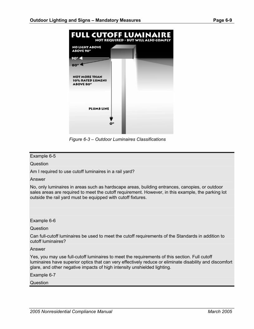
Outdoor Lighting and Signs – Mandatory Measures Page 6-9
2005 Nonresidential Compliance Manual March 2005
Figure 6-3 – Outdoor Luminaires Classifications
Example 6-5
Question
Am I required to use cutoff luminaires in a rail yard?
Answer
No, only luminaires in areas such as hardscape areas, building entrances, canopies, or outdoor sales areas are required to meet the cutoff requirement. However, in this example, the parking lot outside the rail yard must be equipped with cutoff fixtures.
Example 6-6
Question
Can full-cutoff luminaires be used to meet the cutoff requirements of the Standards in addition to cutoff luminaires?
Answer
Yes, you may use full-cutoff luminaires to meet the requirements of this section. Full cutoff luminaires have superior optics that can very effectively reduce or eliminate disability and discomfort glare, and other negative impacts of high intensity unshielded lighting.
Example 6-7
Question
Page 6-10 - Outdoor Lighting and Signs – Mandatory Measures
2005 Nonresidential Compliance Manual March 2005
A parking lot adjacent to a building is being illuminated by 250-watt wallpacks mounted on the side of the building. Do these wall packs have to be cutoff luminaires? The wall packs are also illuminating the façade of the building, but their main purpose is for parking lot illumination.
Answer
Yes, these 250-watt wallpacks will have to be cutoff luminaires because their main purpose is for parking lot illumination. Luminaire mounting methods or locations do not necessarily determine the purpose of the illumination. Each luminaire must be appropriately assigned to the function area that it is illuminating, whether it is mounted to a pole, building, or other structure. Only wallpacks that are 175-watt or less can be non-cutoff.
Example 6-8
Question
Can we use 250-watt, non-cutoff wallpacks for building façade lighting?
Answer
No, Even though façade lighting is exempt from the cutoff requirements, you cannot use non-cutoff wallpacks for façade lighting since most of the light from these fixtures will not illuminate the façade to which they are attached. Only cutoff wallpacks will ensure that most of the light exiting the fixture will illuminate the façade, rather than other areas, such as the parking lots near by. Only wallpacks that are 175-watt or less can be non-cutoff.
Example 6-9
Question
If a cutoff or full-cutoff luminaire is mounted at a tilt does it still meet the cutoff requirement?
Answer
It depends. Luminaires that meet the cutoff requirements when mounted at 90° to nadir may or may not comply with the cutoff requirement when they are mounted at a tilt. In order for a tilted luminaire to meet this requirement a photometric test report must be provided showing that the luminaire meets the cutoff requirements at the proposed tilt, or other non-level mounting condition.
6.2.4 Automatic Shutoff Controls §132(c)1.
All permanently installed outdoor lighting must be controlled by a photocontrol or astronomical time switch that automatically turns off the outdoor lighting when daylight is available.
Automatic time switch control devices used to control outdoor lighting shall:
• Be capable of programming different schedules for weekdays and weekends; and
• Have program backup capabilities that prevent the loss of the device's program and time setting for at least 10 hours if power is interrupted.
Outdoor astronomical time-switch controls used to control outdoor lighting shall:

Outdoor Lighting and Signs – Mandatory Measures Page 6-11
2005 Nonresidential Compliance Manual March 2005
• Contain at least 2 separately programmable channels per function area; and
• Have the ability to independently offset the on and off times for each channel by 0 to 99 minutes before or after sunrise or sunset; and
• Have sunrise and sunset prediction accuracy within +/- 15 minutes and timekeeping accuracy within 5 minutes per year; and
• Store time zone, longitude and latitude in non-volatile memory; and
• Display date/time, sunrise and sunset; and
• Have an automatic daylight savings time adjustment; and
• Have automatic time switch capabilities specified in §119 (c).
This requirement does not apply for lighting in parking garages, tunnels, and large covered areas that require illumination during daylight hours.
Controls used to meet this requirement shall be certified by the manufacturer and listed in the Energy Commission directory.
6.2.5 Multi-Level Switching §132(c)2.
For building facades, parking lots, garages, sales and non-sales canopies, and all outdoor sales areas, where two or more luminaires are used, automatic controls are required to provide the owner with the ability to turn off the lighting or to reduce the lighting power by at least 50% but not exceeding 80% when the lighting is not needed. This switching scenario is sometimes referred to as multi-level switching. Continuous dimming control strategies also satisfy this requirement as long as their dimming range encompasses the 50% to 80% power reduction range.
Exceptions apply to:
• Lighting required by a health or life safety statute, ordinance, or regulation, including but not limited to, emergency lighting.
• Lighting for steps or stairs that require illumination during daylight hours.
• Lighting that is controlled by a motion sensor and photocontrol.
• Lighting for facilities that have equal lighting requirements at all hours and are designed to operate continuously.
• Temporary outdoor lighting.
• Internally illuminated, externally illuminated, and unfiltered signs
There are a number of options available to meet the requirements of this section. Following are a few examples:
• Dimmable lighting systems can be used to meet the outdoor multi-level switching requirements. For HID fixtures, the hi-lo strategy or continuous dimming capable of reducing the connected lighting power by 50% to 80% may be used. For HID and LED fixtures, stepped
Page 6-12 - Outdoor Lighting and Signs – Lighting Zones
2005 Nonresidential Compliance Manual March 2005
dimming is acceptable provided that all the steps are within the 50% to 80% range. LED continuous dimming strategies are acceptable as long as their dimming capacity encompasses the 50% to 80% range. LEDs represent an attractive choice as they can be inexpensively and reliably dimmed.
• When there are two or more fixtures on a single pole, the fixtures can be switched separately
• Every other fixture or pole can be switched separately. This is also known as checkerboard switching
• Every other row of fixtures or poles can be switched separately
• The front half of a parking lot can be switched separately from the back half or sides of the parking lot
• Equip the lighting systems with motion sensors and photoelectric switches. This option works well with fluorescent and LED sources. HID sources may employ the hi-lo strategy with motion sensors.
• Automatic controls to reduce outdoor lighting by at least 50% but not exceeding 80% are required with all of these strategies
Example 6-10
Question
Will a circuit breaker meet the multi-level switching requirements?
Answer
No, circuit breakers are not considered automatic switching. The Standards define automatic as being capable of operating without human intervention.
Example 6-11
Question
The Standards specify that the automatic multi-level switch must be able to reduce the outdoor lighting power by at least 50%, but not exceeding 80%, for certain lighting applications. Can any point between 50% and 80% be chosen to satisfy this requirement?
Answer
Yes, any point between 50% and 80% will satisfy this requirement. This may be a single point or multiple points, as long as they are within this range. Continuous dimming systems also satisfy this requirement as long as their dimming capacity falls in the 50% to 80% range.
6.3 Lighting Zones
6.3.1 Overview §10-114
An important part of the Standards is to base the outdoor lighting power that is allowed, on how bright the surrounding conditions are. The Standards contain

Outdoor Lighting and Signs – Lighting Zones Page 6-13
2005 Nonresidential Compliance Manual March 2005
lighting power allowances for newly installed equipment and specific alterations that are dependent on which Lighting Zone the project is located in.
The technical basis for these differences described by the Illuminating Engineering Society of North America (IESNA), is that the eyes adapt to darker surrounding conditions, and less light is needed to properly see; when the surrounding conditions get brighter, more light is needed to see. The least power is allowed in Lighting Zone 1 and increasingly more power is allowed in Lighting Zones 2, 3, and 4. Providing greater power than is needed potentially leads to debilitating glare, to an increasing spiral of brightness as over-bright projects become the surrounding conditions for future projects causing future projects to unnecessarily require greater power, and to wasting of energy.
The Energy Commission defines the boundaries of Lighting Zones based on U.S. Census Bureau boundaries for urban and rural areas as well as the legal boundaries of wilderness and park areas (see Standards Table 10-114-A). By default, government designated parks, recreation areas and wildlife preserves are Lighting Zone 1; rural areas are Lighting Zone 2; and urban areas are Lighting Zone 3. Lighting Zone 4 is a special use district that may be created by a local government.

Page 6-14 - Outdoor Lighting and Signs – Lighting Zones
2005 Nonresidential Compliance Manual March 2005
Table 6-2 – Standards Table 10-114-A Lighting Zone Characteristics and Rules for Amendments by Local Jurisdictions
Zone Ambient Illumination
State wide Default Location Moving Up to Higher Zones Moving Down to Lower Zones
LZ1 Dark Government designated parks, recreation areas, and wildlife preserves. Those that are wholly contained within a higher lighting zone may be considered by the local government as part of that lighting zone.
A government designated park, recreation area, wildlife preserve, or portions thereof, can be designated as LZ2 or LZ3 if they are contained within such a zone.
Not applicable.
LZ2 Low Rural areas, as defined by the 2000 U.S. Census.
Special districts within a default LZ2 zone may be designated as LZ3 or LZ4 by a local jurisdiction. Examples include special commercial districts or areas with special security considerations located within a rural area.
Special districts and government designated parks within a default LZ2 zone maybe designated as LZ1 by the local jurisdiction for lower illumination standards, without any size limits.
LZ3 Medium Urban areas, as defined by the 2000 U.S. Census.
Special districts within a default LZ3 may be designated as a LZ4 by local jurisdiction for high intensity nighttime use, such as entertainment or commercial districts or areas with special security considerations requiring very high light levels.
Special districts and government designated parks within a default LZ3 zone may be designated as LZ1 or LZ2 by the local jurisdiction, without any size limits.
LZ4 High None. Not applicable. Not applicable.
6.3.2 Lighting Zone Adjustments by Local Jurisdictions §10-114 Table 10-114-A
The Energy Commission sets statewide default Lighting Zones. However, the jurisdictions (usually a city or county), may change the zones to accommodate local conditions. Local governments may designate a portion of Lighting Zones 2 or 3 as Lighting Zone 4. The local jurisdiction also may designate a portion of Lighting Zone 3 to Lighting Zone 2 or even Lighting Zone 1. When a local jurisdiction adopts changes to the Lighting Zone boundaries, it must follow a public process that allows for formal public notification, review, and comment about the proposed change. The local jurisdiction also must provide the Energy Commission with detailed information about the new Lighting Zone boundaries, and submit a justification that the new Lighting Zones are consistent with the specifications in §10-114 of the Standards.
The Energy Commission has the authority to disallow Lighting Zone changes if it finds the changes to be inconsistent with the specification of Standards Table 10-114-A or §10-114.
Following is a summary of the provisions of §10-114:

Outdoor Lighting and Signs – Lighting Zones Page 6-15
2005 Nonresidential Compliance Manual March 2005
Options for Parks, Recreation Areas and Wildlife Preserves The default for government designated parks, recreation areas, and wildlife preserves is Lighting Zone 1. The local jurisdiction having authority over the property will know if the property is a government designated park, recreation area, or wildlife preserve. However, when a park, recreation area, wildlife preserve, or portions thereof, are surrounded by urban areas (as defined by the U.S. Census Bureau), such areas may be designated as Lighting Zone 3 by adoption of the local jurisdiction. Similarly, a Lighting Zone 2 designation can be adopted if the area is surrounded by rural areas (as defined by the U.S. Census Bureau).
Options for Rural Areas The default for rural areas, as defined by the U.S. Census Bureau, is Lighting Zone 2. However, local jurisdictions having building permit authority may designate certain areas as either Lighting Zone 3 or Lighting Zone 4 if the local jurisdiction determines that ambient lighting levels are higher than typical for a rural area. Examples of areas that might be designated Lighting Zone 3 are special commercial districts or areas with special security considerations.
Local jurisdictions also may designate default Lighting Zone 2 areas as Lighting Zone 1, which would establish lower lighting power for outdoor areas with lower surrounding brightness. An example of an area that might be changed to Lighting Zone 1 would include an underdeveloped area within a default Lighting Zone 2 area.
Options for Urban Areas The default for urban areas, as defined by the U.S. Census Bureau, is Lighting Zone 3. Local jurisdictions may designate areas to Lighting Zone 4 for high intensity nighttime use, such as entertainment or commercial districts or areas with special security considerations requiring very high light levels.
Local jurisdictions also may designate areas as Lighting Zone 2 or even Lighting Zone 1 if they deem that this is appropriate.
How to Determine the Lighting Zone for an Outdoor Lighting Project
Permit applicants may determine the Lighting Zone for a particular property through the following steps:
Step 1 - Check with the local jurisdiction having authority over permitting of the property. The local jurisdiction will know if the property is a government designated park, recreation area, or wildlife preserve, and therefore in default Lighting Zone 1. The local jurisdiction also may know if the property is contained within the physical boundaries of a Lighting Zone for which a locally-adopted change has been made. However, verify through step 3 that a locally-adopted change has been submitted to the Energy Commission.
Step 2 - Look at the U.S. Census website to determine if the property is within a rural (statewide default Lighting Zone 2) or urban (statewide default Lighting Zone 3) census tract.

Page 6-16 - Outdoor Lighting and Signs – Lighting Zones
2005 Nonresidential Compliance Manual March 2005
Step 3 - Check the Energy Commission’s website to determine if the property is contained within the physical boundaries of a Lighting Zone that has been changed through a local jurisdiction adoption process.
How to Use the U.S. 2000 Census map to determine the default Lighting Zone (LZ)
Go to the US Census page, year 2000 geographic map
http://factfinder.census.gov/servlet/AdvancedGeoSearchMapFramesetServlet?_lang=en&_command=getPlacenames
The US Census Website provides a handy way to determine if a property is in rural (statewide default Lighting Zone 2) or urban (statewide default Lighting Zone 3) census tract.
A link to the U.S. Census Bureau can be found on the California Energy Commission web site: http://www.energy.ca.gov.
Energy Commission Web-based List The Energy Commission maintains a web-based list of local adjustments to the default Lighting Zones. Jurisdictions are required to notify the Energy Commission of the change in designation, with a detailed specification that includes the following information:
• The boundaries of the adopted Lighting Zones, consisting of the county name, the city name if any, the zip code(s) of the re-designated areas, and a description of the physical boundaries within each zip code.
• A description of the public process that was conducted in adopting the Lighting Zone changes.
• An explanation of how the adopted Lighting Zone changes are consistent with the specifications in the Standards.
There are basically two ways to define the physical boundaries of an adopted Lighting Zone: by defining either a single corridor, or defining an area within specific boundaries.
1. Examples of defining a single corridor:
• Properties with frontage on Mazi Memorial Expressway, between Hana Avenue and Elizabeth Street to a depth of 50 feet from each frontage property line.
• The area 500 feet east of Interstate 5, from 500 feet north of Gary Ave to 250 feet south of West William Way.
• The area of the Sara Bike Trail starting at Bryan Avenue and going east to Eurlyne Park, the width of a path which is from the edge of the South Fork of the Randel River on one side, to 100 feet beyond the paved bike trail, or to private property lines, whichever is shorter, on the other side.
2. Example of using an area within specific, well-delineated boundaries:

Outdoor Lighting and Signs – Lighting Zones Page 6-17
2005 Nonresidential Compliance Manual March 2005
• The area that is bounded by the Nelson River on the west, Elaine Lane on the south, Jon Road on the east, and the boundary of Beverly County on the north.
Note: The physical boundaries of a changed Lighting Zone are not required to coincide with the physical boundaries of a census tract.
Figure 6-4 – Example of US Census Bureau Information
Example 6-12
Question
I want to have the default outdoor Lighting Zone for a particular piece of property changed. How do I accomplish that?

Page 6-18 - Outdoor Lighting and Signs – General Site Illumination
2005 Nonresidential Compliance Manual March 2005
Answer
Check with the local jurisdiction having authority over the property and ask them what you need to do to petition them to have the default outdoor Lighting Zone officially adjusted.
6.4 Outdoor Lighting Power Allowances An outdoor lighting installation complies with Standards if the actual outdoor lighting power is no greater than the allowed outdoor lighting power. This section describes the procedures and methods for complying with §147(a).
The allowed lighting power is determined by measuring the area or length of the lighting application and multiplying this area or length times the Lighting Power Allowance, which is expressed either in W/ft² or W/ft, respectively. The allowed lighting power must be calculated for either the general illumination of the site, or for specific applications.
The area of the lighting application must be defined exclusive of any areas on the site that are not illuminated. All outdoor luminaires must be assigned to a specific function area that each is respectively illuminating.
The actual lighting power of outdoor lighting is the total watts of all lighting systems (including ballast or transformer loss). See §147(b).
The allowed outdoor lighting power is calculated by Lighting Zone as defined in §10-114. Local governments may amend Lighting Zones in compliance with §10-114.
6.5 General Site Illumination (§147(a))Table 147-A
The Standards impose maximum lighting power limits for general site illumination. General site illumination includes those applications listed in Standards Table 147-A (see also the first column of Table 6-1). These include:
• Hardscape for automotive vehicular use, including parking lots, driveways and site roads.
• Hardscape for pedestrian use, including plazas, sidewalks, walkways and bikeways.
• Building entrances (without canopy).
• Outdoor sales lots.
Hardscape is an improvement to a site that is paved and has other structural features, including but not limited to, curbs, plazas, entries, parking lots, site roadways, driveways, walkways, sidewalks, bikeways, water features and pools, storage or service yards, loading docks, amphitheaters, outdoor sales lots, and private monuments and statuary.
A single lighting budget may be determined for all of these applications together and tradeoffs may be made between the general site illumination applications.

Outdoor Lighting and Signs – General Site Illumination Page 6-19
2005 Nonresidential Compliance Manual September 2005
Other outdoor lighting applications are considered specific applications as opposed to general site illumination. No tradeoffs may be made among or between specific applications.
The allowed lighting power for general site illumination is calculated by determining the area or length of each lighting application and multiplying this area or length times the lighting power allowance, which is expressed either in W/ft² or W/ft, respectively. The area for general illumination of the site may not include areas for specific applications.
The actual lighting power of outdoor lighting is the total watts of all lighting systems (including ballast or transformer loss). See §147(b).
Example 6-13
Question
In a parking lot in front of a retail store, we are not using the maximum lighting power allowance for the parking lot. Can we use the remaining allowance to illuminate the building entrance and the walkways near the store to a higher level?
Answer
Yes, you may use the unused portion of the power allowance in the parking lot to increase the illumination levels for other general site illumination lighting applications in Standards Table 147-A, including building entrance without canopies and walkway areas. However, this tradeoff is not allowed for lighting applications included in Standards Table 147-B.
6.5.1 Illuminated Area
The area of the lighting application may not include any areas on the site that are not illuminated. An area is considered illuminated if it is located within three mounting heights of the nearest luminaire. With indoor lighting applications, the entire floor area is considered to be illuminated for the purpose of determining the allowed lighting power. However, for outdoor lighting applications, the number of luminaires, their mounting heights and their layout affect the illuminated area and therefore the allowed lighting power.
In plan view of the site, the illuminated area is defined as any area within a square pattern around each luminaire or pole that is six times the luminaire mounting height, with the luminaire in the middle of the pattern, less any area that is within a building, under a canopy, beyond property lines, or obstructed by a sign or structure.
The area for general site illumination shall not include any specific applications as defined in Standards Table 147-B. Specific lighting applications must each comply with their own allowed lighting power.
The area of parking lots (including related automobile circulation) and pedestrian plazas is the actual paved area that is illuminated. Planter boxes and other landscaped areas are included as illuminated area, as long as they are less than 10 ft wide and enclosed on at least three sides.
However, for roadways, driveways, sidewalks, walkways or bikeways, the maximum allowed illuminated area may be determined by either of the following methods:

Page 6-20 - Outdoor Lighting and Signs – General Site Illumination
2005 Nonresidential Compliance Manual March 2005
i. The illuminated area may include the actual paved area plus 5 ft on either side of the centerline path of travel. The lighting power allowance with this method is watts per ft2.
ii. A 25 ft wide area running along the axis of the path of travel and including as much of the paved area of the site roadway, driveway, sidewalk, walkway or bikeway as possible. Any overlapping area of another lighting application must be subtracted from the area of the other lighting application. In this case the allowed lighting power is the length of the centerline of the path times the allowed power per unit length. The lighting power allowances are shown as watts per linear foot in Standards Table 147-A for this calculation method.
With either of the above methods, the illuminated area may not extend beyond the property line.
6.5.2 Lighting Applications
Determine the appropriate lighting application from Standards Table 147-A for each portion of general site illumination. Multiply the allowed area, or length if using hardscape method (ii), of each lighting application by the allowed lighting power density from Standards Table 147-A. Each portion of the illuminated area must be assigned to only one lighting application, and the assigned lighting applications must be consistent with the actual use of the area. Any specific lighting applications (listed in Standards Table 147-B) are excluded from the general site illumination.

Outdoor Lighting and Signs – General Site Illumination Page 6-21
2005 Nonresidential Compliance Manual March 2005
Table 6-3 – Standards Table 147-A General Site Illumination LPD Values
Watts per square feet, unless otherwise noted
Lighting Application Allowed Area
Lighting Zone 1
Lighting Zone 2
Lighting Zone
3
Lighting Zone
4 Hardscape for automotive vehicular use, including parking lots driveways and site roads
Method (i.) Actual paved area plus 5’ perimeter of adjacent unpaved land. Includes planters and landscaped areas less than 10’ wide that are enclosed by hardscape on at least three sides..
0.05 0.08 0.15 0.19
Hardscape for pedestrian use, including, plazas, sidewalks, walkways and bikeways
Method (i.) Actual paved area plus 5 feet of unpaved land on either side of path of travel. Shall include all continuous paved area before including adjacent grounds.
0.06 0.09 0.17 0.21
Hardscape for driveways, site roads, sidewalks, walkways and bikeways
Method (ii.) 25’ wide path incorporating as much of the paved area of the site roadway, driveway, sidewalk, walkway or bikeway as possible.
1.0 w/lf 1.5 w/lf 4.0w/lf 5.0 w/lf
Building Entrances (without canopy)
Width of doors plus 3 ft on either side times a distance of 18 feet outward.
0.35 0.50 0.70 1.00
Outdoor Sales Lot Actual portion of uncovered outdoor sales lot used exclusively for display of vehicles or other merchandise for sale. All adjacent access drives, walkway areas, customer parking areas, vehicle service or storage areas that are not surrounded on at least three sides by sales area shall be considered hardscape.
0.35 0.70 1.25 2.00
Example 6-14
Question
Lighting for stairs is exempt from the requirements of §147, so is a pole-mounted luminaire that is located at the stairs considered exempt, even though some of the light serves hardscape areas that are not exempt?
Answer
In this example, the luminaire is not regulated by the Standards if the primary purpose for that luminaire is to illuminate the stairs (or other unregulated areas), and majority of light coming from a luminaire falls on stairs. However, the luminaire is regulated by the Standards if majority of the light coming from the luminaire falls on regulated areas, such as hardscape areas. For example, if the luminaire is equipped with optics that directs more than 50% of the light towards the stairs, then the luminaire may be considered stair lighting and therefore exempt. Conversely, the luminaire must be considered hardscape lighting if the lack of proper optical controls results in more than 50% of the light fall on the adjacent hardscape areas. Each luminaire on a site plan must be assigned only one area. It is not the intent of the Standards to assign the wattage of any single outdoor luminaire to more than one area

Page 6-22 - Outdoor Lighting and Signs – General Site Illumination
2005 Nonresidential Compliance Manual March 2005
Example 6-15
Question
A 300 ft long 15 ft wide roadway leads through a wooded area to a hotel entrance in Lighting Zone 2, and the owner wants to light the roadway with luminaires mounted at a height of 20 ft. What is the allowed lighting power for this roadway?
Answer
Lighting power for the roadway may be calculated in one of two ways: based on an allowance of 0.08 W/ft² times the area of the pavement plus 5 ft on each side or based on the length of the roadway times 1.5 W/ft. Using the first method, the allowance is the area of 7,500 ft² (300 ft x 25 ft) times the allowance of 0.08 W/ft² or 600 watts. Using the linear foot method, the allowance is 300 ft of length times the allowance of 1.5 W/ft or 450 watts. In this instance, the area method results in a larger lighting power allowance, but this depends on the width of the proposed paved area. A simple calculation (1.5 W/ft ÷ 0.08 W/ft² = 18.75 ft) tells us that the linear foot method will result in more lighting power as long as the width of the roadway (including the 5 ft band on each side) is less than 18.75 ft. In Lighting Zone 3, the breakeven width is 26.67 ft (4.0 W/ft ÷ 0.15 W/ft²).
If the roadway were located along the property line, then the additional 5 ft band may not be added on the side adjacent to the property line, e.g. the 5 ft band may not extend onto neighboring property.
Also, the 600 watts calculated above is the maximum power that is allowed and is based on the assumption that the luminaires are spaced in such a way that the entire roadway is illuminated. With the proposed 20 ft mounting height, as long as the luminaires are spaced closer than 120 ft (6 x 20 ft) apart along the roadway, the entire surface may be considered to be illuminated.
Example 6-16
Question
The parking lot illustrated below has two luminaires that are mounted at a height of 25 ft. What is the area of general site illumination and what is the allowed lighting power? The lot is located in Lighting Zone 3.
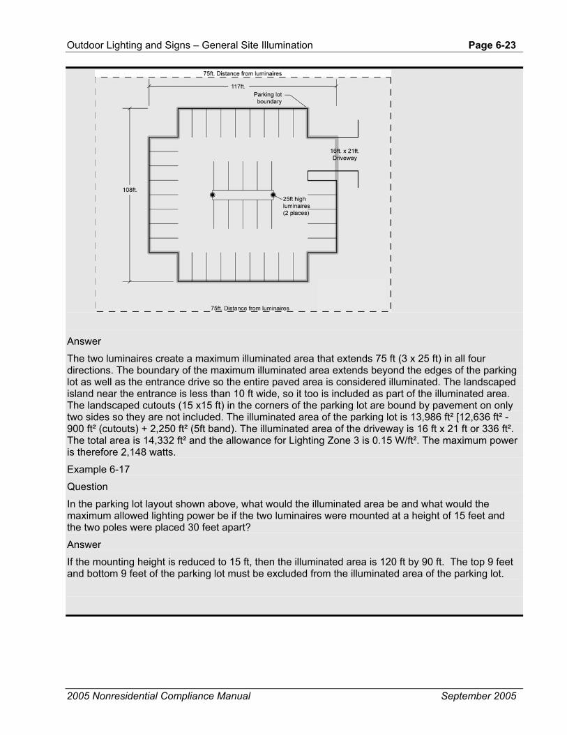
Outdoor Lighting and Signs – General Site Illumination Page 6-23
2005 Nonresidential Compliance Manual September 2005
Answer
The two luminaires create a maximum illuminated area that extends 75 ft (3 x 25 ft) in all four directions. The boundary of the maximum illuminated area extends beyond the edges of the parking lot as well as the entrance drive so the entire paved area is considered illuminated. The landscaped island near the entrance is less than 10 ft wide, so it too is included as part of the illuminated area. The landscaped cutouts (15 x15 ft) in the corners of the parking lot are bound by pavement on only two sides so they are not included. The illuminated area of the parking lot is 13,986 ft² [12,636 ft² - 900 ft² (cutouts) + 2,250 ft² (5ft band). The illuminated area of the driveway is 16 ft x 21 ft or 336 ft². The total area is 14,332 ft² and the allowance for Lighting Zone 3 is 0.15 W/ft². The maximum power is therefore 2,148 watts.
Example 6-17
Question
In the parking lot layout shown above, what would the illuminated area be and what would the maximum allowed lighting power be if the two luminaires were mounted at a height of 15 feet and the two poles were placed 30 feet apart?
Answer
If the mounting height is reduced to 15 ft, then the illuminated area is 120 ft by 90 ft. The top 9 feet and bottom 9 feet of the parking lot must be excluded from the illuminated area of the parking lot.
Page 6-24 - Outdoor Lighting and Signs – General Site Illumination
2005 Nonresidential Compliance Manual March 2005
6.5.3 Adjustments to Outdoor Lighting Power Allowances
The general site outdoor lighting power allowances permit lighting designs that deliver appropriate light levels as recommended by the Illuminating Engineering Society of North America (IESNA). In addition, the lighting power allowances are based on meeting IESNA recommendations for illumination quantity and quality and through the use of reasonably efficient sources and equipment that are readily available on the market. Minimum safety requirements have already been taken into consideration. Conservative assumptions were used in developing the Standards so, most often, it is possible to achieve illumination levels considerably higher than the minimums recommended by IESNA by simply using different performance parameters than were used to develop the lighting power allowances. The different performance parameters could include a more efficacious lighting technology, like pulse-start metal halide lamps or high-pressure sodium lamps, and by using cutoff rather than full-cutoff luminaires.
Adjustments For Local Ordinances Exception 1 to 147(c)1.B. Table 147-C
When higher light levels are required by law, through an officially adopted local ordinance by the authority having jurisdiction, and when the allowed lighting power density is inadequate to provide the required higher light levels using efficient lighting technologies (like pulse start metal halide, fluorescent T8 and T5 sources, or high pressure sodium lighting systems), then the allowed lighting power density specified in Table 147-C may be used to meet the higher light levels (See Exception 1 to §147(c)1.B.). This exception applies to general site illumination only and in particular to parking lots, site roadways, driveways, sidewalks, walkways, and bikeways. The higher value from Standards Tables 147-A or 147-C may be used for such applications.
The LPD values in Table 147-C are based on “average” footcandle levels. If the local ordinance calls for “minimum” footcandle levels, multiply the “average” footcandle levels by a factor of two. For example, if a local ordinance calls for “minimum” of one footcandle level, then instead of using the one footcandle level at 0.07 W/ft2, use two footcandle levels at 0.12 W/ft2. If multiplying the “average” footcandle levels result in a value that is greater than four footcandles, simply extrapolate the 0.25 W/ft2 value of the “average” four-footcandle level. For example, a “minimum” of three footcandles is equivalent to six “average” footcandles. Extrapolating for 0.25 W/ft2 results in 0.38 W/ft2.
Table 6-4 – Standards Table 147-C Required Light Levels by Law through a Local Ordinance
Required light levels by law through a local ordinance (horizontal foot-candles, average) Allowed Lighting Power Density (W/ft2)
0.5 0.05
1.0 0.07
1.5 0.10
2.0 0.12
3.0 0.19
4.0 or greater 0.25
Example 6-18

Outdoor Lighting and Signs – General Site Illumination Page 6-25
2005 Nonresidential Compliance Manual March 2005
Question
If the parking lot shown in the previous examples (with 25 ft mounting height) were in a jurisdiction that required a minimum of 2 footcandles of parking lot illumination, what would be the allowed lighting power?
Answer
Referring to Standards Table 147-C, the allowed lighting power density for 2 footcandles is 0.12 W/ft², which is lower than the 0.15 allowed for Lighting Zone 3, so no additional power would be permitted. However, if the local ordinance required an average 3 footcandles, then the maximum lighting power density would be 0.19 W/ft² and lighting power could be increased to 0.19 W/ft² x 17,400 ft² or 3,306 watts.
Adjustments For Security Exception 2 to 147(c)1.B. Table 147-D
In some situations higher lighting levels may be required because of special security requirements. Lighting power may be increased by values in Standards Table 147-D for security reasons in three cases:
• For retail parking lots in Lighting Zones 1, 2, and 3, the lighting power allowance from Standards Table 147-A may be increased by 25% (multiply the value by 1.25).
• For hardscape areas (plazas, pedestrian ways, parking, or roadways) within 100 ft of the entrance of senior housing facilities, the lighting power allowance from Standards Table 147-A may be increased by 25% (multiply the value by 1.25).
• For parking lots and walkways within 60 ft of building entrances for law enforcement, fire, ambulance and emergency vehicle facilities, the lighting power allowance from Standards Table 147-A may be doubled (multiply the value by 2.0).
When the security adjustment is used, the areas affected shall be considered special applications and no tradeoffs are permitted. The area of security lighting is dropped from the area of general site illumination and it is treated as a special use-it-or-lose-it allowance. Luminaires that are used for this special security lighting shall not create illuminated area for the purpose of determining general site illumination.
Table 6-5 – Standards Table 147-D Adjustments for Security
Function Area Multiplier
Retail parking lots in Lighting Zones 1, 2 and 3 1.25
Hardscape areas within 100 feet of the entrance of senior housing facilities in Lighting Zones 1, 2, and 3 1.25
Parking lots and walkways within 60 feet of entrances to the building for law enforcement, fire, ambulance and emergency vehicle facilities
2.0
Example 6-19

Page 6-26 - Outdoor Lighting and Signs – General Site Illumination
2005 Nonresidential Compliance Manual March 2005
Question
If the parking lot in the previous example served a retail store, what would be the lighting power allowance?
Answer
The 2,610 watts may be increased by 25% to 3,262 watts. This is calculated by multiplying the 2,610 watts by 1.25, which is taken from Standards Table 147-D.
Example 6-20
Question
What lighting power is permitted for the parking lot shown below? The site is located in Lighting Zone 3.
Answer
The 20 ft high luminaires create a maximum illuminated area (three mounting heights) that encompasses the entire lot, so the limits of the illuminated area are defined by the paved areas. The landscaped median in the center of the parking lot is more than 10 ft wide so it is not included in the parking lot area. The landscaped areas that are less than 10 ft wide are included as part of the illuminated area.
(100 ft x 140 ft) + (100 ft x 20 ft) – (40 ft x 60 ft) = 13,600 ft²
For Lighting Zone 3, the allowed lighting power is 0.15 W/ft² so the maximum power is 2,040 watts. Each of the four luminaires can be a maximum of about 500 watts.
Example 6-21
Question
A parking lot is illuminated from a series of cutoff wallpacks mounted on an adjacent building. The luminaires are mounted at a height of 15 ft above the ground and spaced 50 ft apart. How large is the illuminated area? What are the maximum rated watts that are permitted for each of the luminaires? The building is located in Lighting Zone 2.
Answer
The illuminated area extends a distance equal to 3 times the mounting height. The illuminated area therefore extends from the building a distance of 45 ft. The total illuminated area is 45 ft x 290 ft or 13,050 ft². The allowed lighting power in Lighting Zone 2 is 0.08 W/ft² so the maximum power is 1,044 watts. Each luminaire can have a maximum size of about 208 watts.
Example 6-22
Question
In the example above, if you substitute sconces for the wall packs and keep the same arrangement on the wall, what would be the allowed lighting power?
Answer
In this case, the allowance would be based on façade lighting, not parking lot lighting. Façade lighting is a specific lighting application so no tradeoffs are permitted with parking lot lighting and the luminaries can not be counted toward creating general site illumination. The Lighting Zone 2 allowance for façade lighting is 0.18 W/ft² and the surface being illuminated is the entire wall. The area of the wall is 260 ft x 20 ft or 5,200 ft². The maximum power is 936 watts.

Outdoor Lighting and Signs – General Site Illumination Page 6-27
2005 Nonresidential Compliance Manual March 2005
Example 6-23
Question
If a pole has a height of 15 ft, what are the dimensions of the square pattern used for power calculations?
Answer
The illuminated area is defined as any area within a square pattern around each luminaire or pole that is six times the luminaire mounting height, with the luminaire in the middle of the pattern, less any area that is within a building, under a canopy, beyond property lines, or obstructed by a sign or structure. Therefore, for a 15-ft pole, the area will be described by a square that is 90 ft (15 ft X 6) on each side, or 8,100 ft2 (90ft x 90ft), minus areas that are beyond the property line or other obstructions.
Example 6-24
Question
If two poles in the center of an illuminated area are a greater distance than 6 times the mounting height, will all of the square footage between them be included in the area?
Answer
The illumination area for each pole is determined as the area within a square pattern around each pole that is six times the luminaire height (usually the pole height). In most applications, for example parking lots, these square patterns will overlap, so the entire area of the parking lot may be used as the basis for the lighting power budget. However, if the poles are so far apart that squares do not overlap, then each square determines the illumination area for each pole for the purpose of lighting budget. In this case the entire parking lot area may not be used for the basis of lighting budget. This procedure means that unlighted areas are not used for allowed power calculations.
Example 6-25
Question
Is the parking lot outside of a hospital (“I” occupancy) regulated by the Standards?
Answer
No. Hospitals are “I” type occupancies and are not covered by Title 24 Building Energy Standards. This includes all outdoor areas. The same is true for all other “I” type occupancies such as detention facilities.
Example 6-26
Question
How do I determine if I should use the actual paved area (watts per ft2 allowance) or a 25-ft wide area (watts per linear foot allowance)?
Answer
You may try both lighting budget calculations and choose the one that is most appropriate for to your situation.
Example 6-27
Question

Page 6-28 - Outdoor Lighting and Signs – Specific Lighting Applications
2005 Nonresidential Compliance Manual March 2005
We have a five-story parking garage. The top level is uncovered. What are the lighting Standards requirements for this garage?
Answer
Since the lower four floors have a roof, they are considered indoor unconditioned buildings and must comply with the requirement of Standards Table 146-C. For these levels, indoor compliance forms LTG-1-C, LTG-2-C, and LTG-3-C may be required. The uncovered top floor is considered a parking lot and therefore must comply with the hardscape requirements of Standards Table 147-A. An outdoor lighting compliance form, such as OLTG-1-C and OLTG-2-C may be required for the top level.
Example 6-28
Question
Our overflow parking lot is covered with gravel. Is this parking lot considered “hardscape” and must it comply with Table 147-A requirements?
Answer
Yes, parking lots covered with gravel, or any other material used to enhance the surface to accommodate parking or travel, such as pavers, asphalt, cement, or other pervious or non-pervious materials are considered hardscape and must comply with the requirements for hardscape areas.
Example 6-29
Question
What is the allowed lighting power for a 15,000 ft2 retail parking lot located in Lighting Zone 2?
Answer
Standards Table 147-A specifies a lighting power density of 0.08 W/ft² for hardscape including parking lots in Lighting Zone 2 (hardscape for automotive use, method i). Since this is a retail parking lot, Standards Table 147-D, permits a multiplier of 1.25, which can be used to increase the allowed power. The maximum allowed lighting power for this parking lot is therefore:
0.08 W/ft² x 1.25 x 15,000 ft² = 1,500 watts
Example 6-30
Question
We believe that we need more lighting power than Standards allow. Can we use Standards Table 147-C to get more power?
Answer
There must be an officially adopted local ordinance by the jurisdiction having authority that permits higher illumination levels before Standards Table 147-C can be used.
6.6 Specific Lighting Applications §147(a) Table 147-B
The allowance for specific lighting applications are given in Standards Table 147-B. These include

Outdoor Lighting and Signs – Specific Lighting Applications Page 6-29
2005 Nonresidential Compliance Manual March 2005
• Building facades.
• Outdoor sales street frontage.
• Vehicle service stations with or without canopies.
• Vehicle service station hardscape.
• All other sales canopies.
• Non-sales canopies.
• Ornamental lighting.
• Drive up windows.
• Guarded facilities.
• Outdoor dining.
Each of these specific lighting applications shall comply with the standard on their own. Tradeoffs are not permitted between specific lighting applications or with general site illumination.
The allowed lighting power for specific lighting applications is the smaller of the product of the area of the each lighting application and the allowed lighting power density foot from Standards Table 147-B, or the actual power used to illuminate this area. Luminaires qualifying for these allowances shall not be used to determine allowed lighting power for general site illumination or any other specific application.
6.6.1 Building Facades §147(c)2.A.
A building façade is the exterior surfaces of a building, not including horizontal roofing, signs, and surfaces not visible from any reasonable viewing location. Building facades and architectural features may be illuminated by flood lights, sconces or other lighting attached to the building. Building façade lighting is not permitted in Lighting Zone 1. Only the illuminated façade area may be counted when calculating the allowance for façade lighting. Façade orientations that are not illuminated and façade areas that are not illuminated because the lighting is obstructed shall not be included. General site illumination and/or lighting for other specific applications can be attached to the side of a building and not be considered façade lighting. However, every luminaire must be assigned to only one specific lighting application. Unshielded wallpacks mounted on sides of the buildings are not considered façade lighting, since most of the light exiting these fixtures lands on areas other than the building façade.
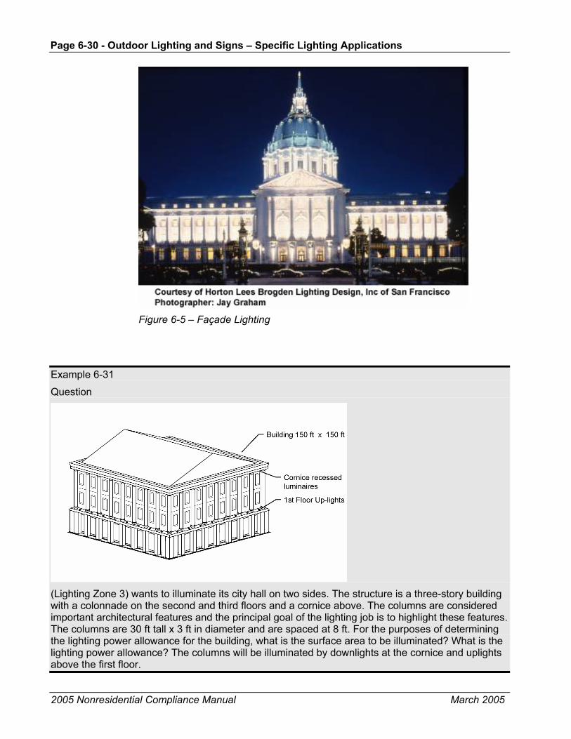
Page 6-30 - Outdoor Lighting and Signs – Specific Lighting Applications
2005 Nonresidential Compliance Manual March 2005
Figure 6-5 – Façade Lighting
Example 6-31
Question
(Lighting Zone 3) wants to illuminate its city hall on two sides. The structure is a three-story building with a colonnade on the second and third floors and a cornice above. The columns are considered important architectural features and the principal goal of the lighting job is to highlight these features. The columns are 30 ft tall x 3 ft in diameter and are spaced at 8 ft. For the purposes of determining the lighting power allowance for the building, what is the surface area to be illuminated? What is the lighting power allowance? The columns will be illuminated by downlights at the cornice and uplights above the first floor.

Outdoor Lighting and Signs – Specific Lighting Applications Page 6-31
2005 Nonresidential Compliance Manual March 2005
Answer
The area of the façade for the purposes of calculating the lighting allowance is the projected area of the illuminated façade. Architectural features such as columns, recesses, facets, etc. are ignored. The illuminated area is therefore 30 ft x 150 ft or 4,500 ft². The façade allowance for Lighting Zone 3 is 0.35 W/ft², so the total power allowed is 1,575 watts.
Example 6-32
Question
I am designing a high-rise building and permanently mounted marquee like lights will be installed along the corners of the building. The lights will be turned on at night, but only for the holiday season, roughly between mid-November and mid-January. The lights consist of a series of 9 watt compact fluorescent luminaires spaced at 12 in. on-center (OC) along all the corners of the building and along the top of the building. Essentially, the lights provide an outline of the building. For the purposes of the outdoor lighting Standards, are these considered façade lighting? Since they will only be used for about two months of the year, are they considered temporary lighting and exempt?
Answer
The lighting is permanent lighting and must comply with the Standards. Temporary lighting is defined as “cord and plug” lighting. Anything that is permanently mounted to the building is considered permanent lighting, and the hours of intended use do not affect its status as permanent lighting.
Since this lighting is primarily used to accent the architectural outline of the building, it may be considered façade lighting. And since all corners of the building are illuminated, all four facades may considered to be illuminated. The area on each façade is 80 ft x 100 ft or 8,000 ft². The total illuminated area is four times 8,000 ft² or 32,000 ft². The Lighting Zone 3 allowance for façade lighting is 0.35 W/ft² and the total power allowance for façade lighting is 11,200 watts.
There are 100 ft x 4 plus 80 ft x 4 lamps (a total of 720 lamps) on the building. Each lamp is 13 watts (including the ballast). This data is taken from Appendix NB of the Nonresidential ACM Manual. The

Page 6-32 - Outdoor Lighting and Signs – Specific Lighting Applications
2005 Nonresidential Compliance Manual March 2005
installed power is 720 lamps times 13 W/lamp or 9,360 watts. The installed power is less than the allowance so the façade lighting complies. If this building were in Lighting Zone 2, the allowance would be 0.18 W/ft² or a total of 5,760 watts. The lighting design would not comply in Lighting Zone 2.
Example 6-33
Question
In the example above, if only the front corners the building are illuminated, which façade area should be the basis of the allowed lighting calculations?
Answer
Since the corners are at the intersection of two facades (for example, the front and right facades), only one or the other facades areas (but not both) may be used to calculate the power allowance.
Example 6-34
Question
Portions of the front façade of a proposed wholesale store in Lighting Zone 3 are going to be illuminated. The front wall dimensions are 120 ft by 20 ft. There is 250 ft2 of fenestration in the front wall that is illuminated by the façade lighting. Signs cover another 500 ft2 of the front wall, and another 400 ft2 is not illuminated at all. What is the allowed front façade lighting power?
Answer
The gross wall area is 2,400 ft2 (120x20). However we must subtract all those areas that are not illuminated. Please note that since the 250 ft2 of fenestration is intended to be illuminated by the façade lighting, this area may be included in the total area eligible for power calculations. The areas not eligible for power calculations include:
500 ft² of signs + 400 ft² of unlighted façade = 900 ft²
Net wall area used for façade lighting: 2,400 ft² – 900 ft² = 1,500 ft²
From Table 147-B, the allowed façade lighting power density in Lighting Zone 3 is 0.35 W/ft²
The calculated allowed power based on net wall area is 1,500 ft² x 0.35 W/ft² = 525 watts.
The allowed power is therefore the smaller of actual façade lighting power or 525 watts.
Example 6-35
Question
Is sign lighting part of my façade lighting?
Answer
If lighting is used only to illuminate a sign then that lighting is not part of the façade lighting. However, the sign area must be subtracted from the façade area so that the area is not double counted. The sign lighting must meet the requirements of the Standards for sign energy efficiency or allowed power.
Example 6-36
Question

Outdoor Lighting and Signs – Specific Lighting Applications Page 6-33
2005 Nonresidential Compliance Manual March 2005
Is the lighting of my parapet wall with small wattage lamps decorative lighting considered ornamental or façade lighting?
Answer
Small wattage lamps attached to a building façade is considered façade lighting. Ornamental lighting is defined in Standards as post-top luminaires, lanterns, pendant luminaires, chandeliers, and marquee lighting.
Example 6-37
Question
If I mount a luminaire on the side of my building to illuminate an area is it considered façade lighting or hardscape lighting?
Answer
It depends on the primary intent of the luminaire. For example, if the luminaire is primarily illuminating the walls (such as a sconce), then it should be considered part of the building façade lighting. If on the other hand, the luminaire is primarily illuminating the parking lot beyond (most wall packs), then it should be part of the hardscape lighting. It should be noted that lighting power tradeoffs are not allowed between building façade and hardscape areas, which means you cannot use both allowances for the same luminaire.
6.6.2 Sales Frontage §147(c)2.B.
While outdoor sales areas in the category of general site illumination, the portion of the lot along the street may qualify for additional lighting power. This additional allowance is intended to accommodate the retailers need to highlight merchandise to motorists who drive by their lot. Outdoor sales frontage includes car lots, but can also include any sales activity.
The allowed lighting power for outdoor sales frontage is the smaller of the product of the frontage (in feet) and the allowed lighting power density per foot from Standards Table 147-B, or the actual power used to illuminate the frontage.
Sales frontage is immediately adjacent to the principal viewing location and unobstructed for its viewing length. A corner sales lot may include both sides provided that a different principal viewing location exists for each side. Measured in plan view, only sections of the outdoor sales area that are along the frontage and are within a 3 mounting heights of frontage luminaires are eligible for this power allowance. The area within three mounting heights may not be counted as part of the outdoor sales lot.
Luminaires qualifying for this allowance must be located in plan view between the principal viewing location and the frontage outdoor sales area.

Page 6-34 - Outdoor Lighting and Signs – Specific Lighting Applications
2005 Nonresidential Compliance Manual March 2005
Figure 6-6 – Outdoor Sales Frontage
Example 6-38
Question
A 150ft X 300 ft car lot has 4,000 ft² of walkways, 2,000 ft² of driveways, and the rest is the main sales lot. The frontage is 150 ft long and is equipped with luminaires atop 20 ft high poles. What is the area of the main sales lot and what are the maximum power allowances for various lighting applications, if this car lot is located in Lighting Zone 3?

Outdoor Lighting and Signs – Specific Lighting Applications Page 6-35
2005 Nonresidential Compliance Manual March 2005
Answer
The depth of the frontage area is three times the pole height, which is 20 ft x 3 = 60 ft. Therefore the area covered by the frontage luminaires is 60 ft X 150 ft = 9,000 ft².
Total area of the car lot is 150 ft X 300 ft = 45,000 ft². The area of the main sales lot is therefore 45,000 ft² – 4,000 ft² – 2,000 ft² – 9,000 ft² = 30,000 ft². Power allowances for this lot are:
Walkways: 4,000 ft² X 0.17 W/ft² (Standards Table 147-A) = 680 watts
Driveway: 2,000 ft² X 0.15 W/ft² (Standards Table 147-A) = 300 watts
Frontage: 150 ft X 38.5 W/lf (Standards Table 147-B) = 5,778 watts
Main sales lot: 30,000 ft² X 1.25 (Standards Table 147-A) = 37,500 watts
6.6.3 Lighting Vehicle Service Stations §147(c)2.F.
Vehicle service station is a gasoline or diesel dispensing station. The allowed lighting power for vehicle service stations is the same whether or not they have a canopy. In the instance where there is a canopy, the area is the horizontal projected area of the canopy (or the canopy drip line). In the case where there is no canopy, the area is 500 ft² per double sided fuel dispenser and 250 ft² per single sided fuel dispenser.
The lighting power allowances are listed in Standards Table 147-B.
Luminaires qualifying for this allowance cannot be used to determine allowed lighting power for general site illumination or for other specific lighting applications.
Figure 6-7 – Vehicle Service Station
Example 6-39
Question
An uncovered vehicle service station in Lighting Zone 2 has six double-sided fuel dispensers. What is the maximum lighting power allowed in this service station?

Page 6-36 - Outdoor Lighting and Signs – Specific Lighting Applications
2005 Nonresidential Compliance Manual March 2005
Answer
500 ft2 is allowed per each double-sided fuel dispenser, therefore, the total allowed area is 500 ft²/dispenser x 6 dispensers = 3,000 ft². From Standards Table 147-B, the allowed power density for vehicle service stations with or without canopies in Lighting Zone 2 is 1.0 W/ft². The calculated allowed power is 3,000 ft² X 1.0 Wft² = 3,000 watts.
6.6.4 Service Station Hardscape Areas
Service station hardscape is paved area around the fuel dispensers that is not part of the area for the fuel dispenser. The lighting power allowances a listed in Standards Table 147-B.
Lighting power used for service station hardscape may not be traded off against other specific lighting applications or against general site illumination. Luminaires qualifying for this allowance cannot be used to determine allowed lighting power for general illumination; for example, this allowance cannot be used for general parking lot illumination.
Figure 6-8 – Service Station Hardscape Areas
Example 6-40
Question
Where does canopy lighting area end and hardscape area start?

Outdoor Lighting and Signs – Specific Lighting Applications Page 6-37
2005 Nonresidential Compliance Manual March 2005
Answer
Plan view of the horizontal projection of the canopy on the ground establishes the area for under canopy lighting power calculations. This area also referred to as the “drip line” of the canopy. All hardscape areas beyond drip line are considered to be service station hardscape areas.
Example 6-41
Question
A 10,000 ft² service station site (exclusive of building) in Lighting Zone 3 has a canopy drip line area of 6,000 ft2. What are the outdoor lighting power allowances for this service station?
Answer
From Standards Table 147-B, the lighting power allowance for the fuel dispenser area is 1.25 W/ft², and the lighting power density for the service station hardscape area is 0.40 W/ft². The hardscape area is the total area of the service station site (10,000 ft²), minus the area of the canopy drip line (6,000 ft²), which is 4,000 ft². The lighting power allowances are therefore:
6,000 ft² X 1.25 W/ft² = 7,500 watts for the canopy area
4,000 ft² X 0.40 W/ft² = 1,600 watts for the hardscape areas.
Lighting for each of these areas shall comply on their own. No tradeoffs are permitted between these applications.
6.6.5 Lighting Under Canopies §147(c)2.D.
A canopy is a permanent structure consisting of a roof and supporting building elements. The space underneath the canopy must be at least partially open, otherwise it is a building. A canopy may be freestanding or attached to surrounding structures. It may also have conditioned space above it, for instance when the first floor of a building is setback.
The lighting power allowance for a canopy depends on its purpose. Service station canopies are treated separately (see the previous section). The two types of canopies addressed in this section are those that are used for sales and those that are not. Non-sales canopies include covered entrances to hotels, office buildings, convention centers and other buildings. Sales canopies specifically cover and protect an outdoor sales area, including garden centers, covered automobile sales lots, and outdoor markets with permanent roofs. The lighting power allowances are listed in Standards Table 147-B.
The area of a canopy is defined as the horizontal projected area, in plan view, directly underneath the canopy. This area is also referred to as the “drip line” of the canopy. Canopy lighting, either sales or non-sales shall comply separately, e.g. trade-offs are not permitted between other specific lighting applications or with general site illumination.
General site lighting or other specific applications lighting, and/or sign lighting that are attached to the sides or top of a canopy, cannot be considered canopy lighting. Every luminaire shall be assigned to only one or the other application. For example, internally illuminated translucent panels on the perimeter of a

Page 6-38 - Outdoor Lighting and Signs – Specific Lighting Applications
2005 Nonresidential Compliance Manual March 2005
canopy are considered Sign lighting, while the lighting underneath the canopy and directed towards the ground is canopy lighting.
Figure 6-9 – Canopy Lighting
Example 6-42
Question
The first floor of an office tower in Lighting Zone 3 is setback 20 ft on the street side. The width of the recessed façade is 150 ft. The primary purpose of the setback (and canopy) is to provide a suitable entrance to the office tower; however, space under the canopy is leased as newsstand, a flower cart and a shoeshine stand. These commercial activities occupy about half of the space beneath the canopy. What is the allowed lighting power?
Answer
The total canopy area is 20 ft x 150 ft or 3,000 ft². The 1,500 ft² used for the flower cart, newsstand and shoeshine stand is considered a sales canopy and the allowance is 1.00 W/ft² or a total of 1,500 watts. The other 1,500 ft² is a non-sales canopy and the allowance is 0.50 W/ft² or a total of 750 watts. Tradeoffs are not permitted between the sales portion and the non-sales portions.
6.6.6 Ornamental Lighting §147(c)2.C.
Ornamental lighting includes post-top luminaires, lanterns, pendant luminaires, chandeliers, and marquee lighting. The allowances for ornamental lighting are listed in Standards Table 147-B.
The allowance is based on the area of the site external to buildings.
Luminaires used for ornamental lighting shall have a rated wattage, as listed on a permanent factory-installed label, of 100 watts or less.

Outdoor Lighting and Signs – Specific Lighting Applications Page 6-39
2005 Nonresidential Compliance Manual March 2005
Figure 6-10 – Ornamental Lighting
Example 6-43
Question
Are bollard luminaires considered ornamental lighting?
Answer
No, Ornamental lighting is defined in Standards as post-top luminaires, lanterns, pendant luminaires, chandeliers, and marquee lighting. Bollard luminaires are used for general illumination and ornamental lighting in not used for general illumination.
Example 6-44
Question
An entrance canopy to a hotel has marquee lighting around the perimeter and the outside edge of the canopy. Additional downlights are mounted on the underside of the entry canopy. Is the marquee lighting considered ornamental lighting? How much lighting power is permitted?
Answer
Yes, this is considered ornamental lighting. The allowed power depends on the Lighting Zone and the area of the site, excluding the building footprint. The allowance for Lighting Zone 2 is 0.01 W/ft² of site area. The Lighting Zone 3 allowance is double that or 0.02 W/ft² of site area.
6.6.7 Drive-up Windows §147(c)2.G.
Drive-up windows are common for fast food restaurants, banks, and parking lot entrances. In order to qualify, a drive-up window must have someone working behind the “window”. Automatic ticket dispensers at parking lots do not count.
The lighting power allowances are listed in Standards Table 147-B.
The area of drive-up windows is the width of the window plus six ft (3 ft on each side of the window) times a maximum distance of 30 ft outward from the window. The distance from the window may not extend beyond the property line or further than 5 ft past the edge of the paving.
Luminaires qualifying for this allowance shall not be used to determine allowed lighting power for general illumination. Drive-up windows shall comply on their

Page 6-40 - Outdoor Lighting and Signs – Specific Lighting Applications
2005 Nonresidential Compliance Manual September 2005
own; tradeoffs are not permitted with other specific lighting applications or with general site illumination. Luminaires qualifying for this allowance cannot be used to determine allowed lighting power for general illumination; for example, this allowance cannot be used for general parking lot illumination.
Figure 6-11 – Drive-up Windows
Example 6-45
Question
A drive-up window in Lighting Zone 2 has width of seven ft. What is the allowed lighting power for this drive-up window?
Answer
The drive-up windows area is the product of the width of the window plus six ft and the distance 30 ft outward from the window. From Standards Table 147-B, the LPD for drive-up windows in Lighting Zone 2 is 0.25 W/ft².
The area is (7 ft + 6 ft) x 30 ft = 390 ft²
The allowed power is 390 ft² X 0.25 w/ft² = 97.5 watts
6.6.8 Guarded Facilities
Guarded facilities, including gated communities, include the entrance driveway, gatehouse, and guardhouse indoor areas that provide access to secure areas controlled by security personnel who stop and may inspect vehicles and vehicle occupants including, identification documentation, vehicle license plates, and vehicle contents.
The guarded facility area includes the guardhouse indoor area plus the product of the entrance width of 25 ft and length of 80 ft, up to the property boundaries. Luminaires qualifying for this allowance shall not be used to determine allowed

Outdoor Lighting and Signs – Specific Lighting Applications Page 6-41
2005 Nonresidential Compliance Manual March 2005
lighting power for general illumination; for example, this allowance cannot be used for general parking lot illumination.
The power allowance for guarded facilities are listed in Standards Table 147-B.
Example 6-46
Question
A guard station to the research campus of a defense contractor consists of a heated and cooled guard station of 300 ft². Vehicles enter to the right of the station and exit to the left. What is the power allowance? The guard station is located in Lighting Zone 2.
Answer
Since the guard station is air conditioned, it must meet the requirements of indoor conditioned buildings, including HVAC, building envelope, and lighting requirements. The indoor power allowance is determined from the Area Category Method; Table 146-C, General Commercial and Industrial Work). The allowance for the driveway is based on 2,000 ft² (the default 25 ft x 80 ft area). The allowance for Lighting Zone 2 is 0.40 W/ft2 so the total power allowance is 800 watts.
Example 6-47
Question
If in the example above the guardhouse is a 100 square-foot unconditioned shack equipped with only a plug-in radiant heater, what would be the allowed power for this guarded facility?
Answer
§147(c)2.H. states that the area of the guarded facility includes the guardhouse interior area and the driveway. So, the total area is 2,100 W/ft2 (2,000 + 100). The allowance for Lighting Zone 2 is 0.40 W/ft2 so the total power allowance is 840 watts.
Example 6-48
Question
Is the guarded facility at the entrance to a residential gated community covered by the Standards?
Answer
Yes, residential guarded facilities are covered by the Standards.
6.6.9 Outdoor Dining
Outdoor dining areas are limited to uncovered hardscape areas used to serve and consume food and beverages. If the outdoor dining area is covered, then the allowance is based on a non-sales canopy (see above). The power allowances are listed in Standards Table 147-B.
Outdoor dining areas are hardscape areas used to serve and consume food and beverages. Luminaires qualifying for this allowance shall not be used to determine allowed lighting power for general illumination; for example, this allowance cannot be used for general parking lot illumination.

Page 6-42 - Outdoor Lighting and Signs – Specific Lighting Applications
2005 Nonresidential Compliance Manual March 2005
Figure 6-12 – Outdoor Dining
Example 6-49
Question
An 11,000 ft2 outdoor area in Lighting Zone 3 is covered by 3,000 ft² of water features, 4,000 ft² of landscaping, 1,000 ft² of walkways, and 3,000 ft² of outdoor dining. What are the outdoor lighting power allowances for this area?
Answer
Only the walkway and the outdoor dining areas are regulated by the Standards. Therefore, the outdoor lighting power allowances are:
1,000 ft² X 0.17 ft² = 170 watts for the walkways, and
3,000 ft² X 0.35 W/ft² = 1,050 watts for the outdoor lighting area
Each of these areas shall comply separately with the Standards. No tradeoffs are permitted.
Table 6-6 – Standards Table 147-B Specific Application LPD Values
Watts per square feet, unless otherwise noted Lighting Application
Lighting Zone 1 Lighting Zone 2 Lighting Zone 3 Lighting Zone 4
Building Facades Not allowed 0.18 0.35 0.50
Outdoor Sales Frontage (Frontage in linear feet)
Not allowed 22.5 w/lf 38.5 w/lf 55 w/lf
Vehicle Service Station with or without Canopies
0.70 1.15 1.45 2.40
Vehicle Service Station Hardscape 0.05 0.20 0.40 0.60
All Other Sales Canopies Not allowed 0.70 1.00 1.25
Non-sales canopies 0.12 0.25 0.50 0.70
Ornamental Lighting Not allowed 0.01 0.02 0.04
Drive Up Windows 0.12 0.25 0.50 0.70
Guarded Facilities 0.19 0.40 0.80 1.10
Outdoor Dining 0.05 0.18 0.35 0.55

Outdoor Lighting and Signs – Alterations and Additions for Outdoor Lighting Page 6-43
2005 Nonresidential Compliance Manual March 2005
6.7 Alterations and Additions for Outdoor Lighting §149
The Standards apply to alterations and additions to outdoor lighting systems. In general, additions are the same as new construction such as the mandatory measures and compliance with lighting power density requirements. The application of the Standards to alternations depends on the scope of the proposed improvements. In general, alterations to existing outdoor lighting systems that for any lighting application, increase the connected lighting load or replace more than 50% of the luminaires shall meet the requirements.
Some or all mandatory measures may apply to altered components. The mandatory requirements include certification of any new lamps and ballasts that are installed if they are the type regulated by the Appliance Efficiency Regulations. Any new lighting controls must meet minimum performance requirements. In addition, control and circuiting requirements (§130 and §132) may also apply: All outdoor lighting altered components must comply with the requirements of §149(b), and §149(b) 1 I.
Lighting alterations generally refers to replacing the entire luminaire, which includes the housing, lamps, ballasts, and louvers or lenses. Simply replacing the lamps and ballasts in an existing fixture is not considered a lighting alteration. Replacing or installing new wiring (see the following paragraph) represents a lighting alteration and a great opportunity to meet the applicable mandatory requirements as described below.
For lighting alterations purposes, rewiring refers to replacement or installation of new wires that serve the circuit between the switches, relays, branch circuits, other control devices, and rewired luminaire(s). In the case where only the wiring in a circuit that connects the switch and the luminaire(s) is being replaced without any alterations to the luminaire(s), the wiring system itself is considered the altered component and must therefore meet the lighting control requirements.
6.7.1 Outdoor Lighting Additions – Mandatory and Lighting Power Density Requirements
§149(a)1. §130, §132
Mandatory Requirements Additions to existing outdoor lighting must meet all of the Standards mandatory measures for the added lighting fixtures. The mandatory requirements include certification of any new lamps and ballasts that are installed if they are the type regulated by the Appliance Efficiency Regulations. Any new lighting controls must meet minimum performance requirements. In addition, control and circuiting requirements apply as follows:
• Minimum lamp efficacy or motion sensors for lamps rated over 100 watts.
• Luminaire cutoff requirements for outdoor lighting fixtures that use lamps rated greater than 175 watts.
• Automatic controls to turn off lights when daylight is available.
Page 6-44 - Outdoor Lighting and Signs – Alterations and Additions for Outdoor Lighting
2005 Nonresidential Compliance Manual March 2005
• Multi-level switching requirements for the added lighting.
Lighting Power Density Requirements The outdoor lighting additions must also comply with lighting power allowances of §147, Tables 147-A and 147-B. These requirements are the same as new construction discussed earlier in this Chapter.
Example 6-50
Question
I am adding a new 20,000 ft2 section to our parking lot. What are the outdoor lighting requirements for the new addition?
Answer
§149(a)1 in the Standards specifies that all additions to existing outdoor lighting systems must comply with prescriptive requirements of §147 and mandatory measures of §130 through §132.
6.7.2 Outdoor Lighting Alterations §149(b)1.I.
Existing outdoor lighting systems are not required to meet the Standards unless they are altered. However, alterations of existing outdoor lighting systems are subject to requirements similar to those in the Standards for alterations of existing indoor lighting systems. Alterations that increase the connected load, or replace more than 50% of the existing luminaires for each lighting application included in Standards Tables 147-A and 147-B, are required to meet the requirements for newly installed equipment.
6.7.3 Outdoor Lighting Alterations – Mandatory Requirements
When altering lighting components in existing outdoor lighting systems mandatory measures apply to the altered lighting systems. The mandatory requirements include certification of any new lamps and ballasts that are installed if they are the type regulated by the Appliance Efficiency Regulations. Any new lighting controls must meet minimum performance requirements. In addition, control and circuiting requirements (§130 through §132) apply as follows:
• Either minimum lamp efficacy or motion sensors for lamps rated over 100 watts when the entire luminaire is replaced.
• Luminaire cutoff requirements for outdoor lighting fixtures that use lamps rated greater than 175 watts. Replacement of parts of an existing luminaire, including installing new ballasts, lamps, reflector or lens, without replacing the entire luminaire does not trigger luminaire cutoff requirements.
• Automatic controls to turn off lights when daylight is available for luminaries that are altered.
• Multi-level switching requirements if the alteration consists of rewiring.

Outdoor Lighting and Signs – Alterations and Additions for Outdoor Lighting Page 6-45
2005 Nonresidential Compliance Manual March 2005
6.7.4 Outdoor Lighting Alterations – Lighting Power Allowance Requirements
If an alteration involves replacing more than 50% of the lighting fixtures in a given outdoor lighting application or results in an increase in the connected lighting load, compliance with lighting power allowances of Tables 147-A and 147-B are required.
§149(b) 1 I specifies that when more than 50% of luminaires are replaced in a given Lighting Application included in Standards Tables 147-A and 147-B, the alteration requirements apply to that function area only and not the adjacent areas.
When it is necessary to calculate the existing wattage to demonstrate that the alteration does not exceed current lighting power allowances, use the same methodology used for new lighting installations found in Chapter 5.
Example 6-51
Question
We are replacing 20% of the existing 250-watt fixtures in a parking lot. Does the cutoff requirement apply to the new and existing fixtures?
Answer
§149 (b) in the Standards specifies that all altered components must meet applicable mandatory requirements, including cutoff control for replacements luminaires. Therefore, all new fixtures that are greater than 175 watts must meet the cutoff requirements of the Standards, even if less then 50% of the luminaires on site are replaced. However, the existing fixtures are not required to be upgraded to cutoff.
Example 6-52
Question
In a service station we are retrofitting all existing light fixtures under the canopy with new lamps, ballasts, reflectors, and lenses, while leaving the fixture housing intact. Does this trigger the alterations requirements for outdoor lighting?
Answer
No, the Standards (§149(b) 1 I), specify that alterations requirements are triggered only when more than 50% of the luminaires are replaced in a given function area, which includes the entire fixture including the internal components and the housing. In this example, since the fixtures are being retrofitted with new components, the alterations requirements of the Standards are not triggered.
Example 6-53
Question
In a service station we are replacing more than 50% of under canopy fixtures. Does this trigger the alteration requirements for outdoor lighting? Do we need to bring non-canopy lighting such as hardscape lighting up to code as well?
Answer
§149(b) 1 I specifies that when more than 50% of luminaires are replaced in a given Lighting Application included in Standards Tables 147-A and 147-B, the alteration requirements apply to that

Page 6-46 - Outdoor Lighting and Signs – Signs
2005 Nonresidential Compliance Manual March 2005
function area only. So, in this example, only the under canopy luminaires must meet the requirements of §147. Hardscapes and other outdoor Lighting Applications other than the canopy need not meet these requirements even if they are included in the permit along with the canopy lighting.
Example 6-54
Question
We are adding new light fixtures to the existing lighting systems in a parking lot. Which Standards requirements are triggered by this alteration?
Answer
Since additional load is being added to the parking lot, the entire parking lot must comply with the lighting power density requirements for the given Lighting Zone. However, only the newly installed lighting system must comply with the applicable mandatory requirements, including control requirements and cutoff controls.
Example 6-55
Question
I am going to change the ballasts in my façade lighting system. Will I be required to meet the new outdoor lighting standard for façade lighting?
Answer
No, the replacing of only lamps or ballasts in outdoor lighting systems is not considered an alteration and does not trigger compliance with outdoor lighting Standards. Replacing entire fixtures will trigger mandatory requirements for the altered (replaced) fixtures only. Replacing more than 50% of the lighting fixtures or adding to the connected lighting load for any outdoor lighting application will trigger the lighting power density requirements of the Standards.
6.8 Signs The sign energy Standards apply to all internally illuminated (cabinet) and externally illuminated signs, whether they are used indoors or outdoors. Examples are internally illuminated and externally illuminated signs, including billboards, off-premise and on-premise signs. They do not apply to unfiltered signs, traffic signs or exit signs. Exit signs must meet the requirements of the Appliance Efficiency Regulations. The sign energy Standards are the same throughout the state and are independent of outdoor Lighting Zones.
New signs must meet the requirements of §130 (c) (mandatory requirements) and Luminaire Power requirements, §148. §130 (c), describes how the wattages of various lighting components are added up to calculate the total luminaire wattage. Compliance with this Section is only required for signs that comply under the Component Performance Approach, described below.
§148 provides two alternative ways to comply with the sign Standards. Both alternatives encourage the use of readily available, cost-effective lighting technology.
• Alternate 1 - Component Performance Approach. This option sets the maximum power (watts) per ft2 of sign. This approach allows sign

Outdoor Lighting and Signs – Signs Page 6-47
2005 Nonresidential Compliance Manual March 2005
makers’ maximum flexibility. It enables companies to introduce, develop and use any promising new lighting technology as long as it meets the power allowance. There are no constraints on the types of lighting equipment that a sign maker can use to comply under this approach, just as long the manufacturer does not exceed the maximum watts allowed for a sign of that size.
• Alternate 2 - Prescriptive Approach. This option uses specific, energy-efficient lighting technologies. This option provides a simple prescriptive approach for using these energy efficient technologies that are already being used by many in the sign industry.
The lighting power used for indoor signs, other than exit signs, does not have to be counted toward the indoor lighting power allowances. Only exit signs that use more than 5 watts per illuminated face are required to be counted toward the indoor lighting power allowance.
The Standards do not apply to unfiltered signs, or to the unfiltered section of an internally or externally illuminated sign. For example, with an internally illuminated cabinet sign with unfiltered incandescent perimeter lights and an unfiltered arrow mounted on top, neither the unfiltered incandescent perimeter lights nor the unfiltered arrow are addressed by the energy Standards, but the internally illuminated section of the cabinet is covered.
Figure 6-13 – Unfiltered Sign
Figure 6-14 – Externally Illuminated Sign Using Flood Lighting

Page 6-48 - Outdoor Lighting and Signs – Signs
2005 Nonresidential Compliance Manual March 2005
6.8.1 Component Performance Method
The first alternative for internally illuminated signs (component performance method) sets a maximum power allowance of 12 W/ft2 times the area of the sign face. For double-faced signs, only the area of a single face can be used to determine the allowed lighting power. However, for deep sign cabinets where the lamps are isolated by an opaque divider so that they illuminate only one sign face, or for irregular shaped signs where the faces are not parallel and the lamps are shielded by an opaque divider so that they illuminate only one sign face, then the total area of all of the sign faces can be used to determine the allowed lighting power. See Standards Table 148-A.
Figure 6-15 – Multi-faced sign Include Area from Each Face When Separated by Opaque Divider
For externally illuminated signs the maximum allowed lighting power is 2.3 W/ft2 times the area that is illuminated without obstruction or interference. One or more fixtures must illuminate the sign area. See Standards Table 148-A.
6.8.2 Prescriptive Approach
The second alternative (prescriptive approach) requires that the sign be illuminated only with one or more of the following light sources (as applicable) or that all light sources be powered by electronic ballasts with a fundamental output frequency not less than 20 kHz:
• High pressure sodium.
• Pulse start and ceramic metal halide.
• Neon.
• Cold cathode.
• Light emitting diodes.

Outdoor Lighting and Signs – Signs Page 6-49
2005 Nonresidential Compliance Manual March 2005
• Barrier coat rare earth phosphor fluorescent lamps (these include most T8 and T5 lamps).
• Compact fluorescent lamps that do not contain a medium base socket (E24/E26).
No other light sources can be used on a sign complying under this option.
Figure 6-16 – Single-faced Internally Illuminated Cabinet Sign with Fluorescent Lamp and Translucent Face
Figure 6-17 – Double-faced Internally Illuminated Cabinet Sign with Fluorescent Lamp and Translucent Faces
Page 6-50 - Outdoor Lighting and Signs – Signs
2005 Nonresidential Compliance Manual March 2005
Table 6-7 – Sign Compliance Alternatives
Prescriptive Component Performance
Internally Illuminated Signs
12 W/ft²
Includes billboards and on-premise signs
Includes indoor and outdoor signs Externally
Illuminated Signs
2.3 W/ft²
Electronic ballasts ≥ 20 kHz OR, one or more of the following light sources Pulse-start and ceramic metal halide High pressure sodium Neon and cold cathode Light emitting diodes (LED) Barrier coat rare earth phosphor fluorescent lamps (includes most T8 and T5 lamps) Compact fluorescent lamps that do not contain medium based sockets. (E24/E26)
Example 6-56
Question
Can I use neon or cold cathode lights in my sign and comply with the Standards under Alternative 2 (Prescriptive Approach)?
Answer
Yes, neon and cold cathode lights are allowed under the prescriptive approach.
Example 6-57
Question
Do signs inside a theater lobby or other indoor environments need to comply with the sign requirements?
Answer
Yes, all internally and externally illuminated signs whether indoor or outdoor must comply with either the prescriptive or component performance approach.
Example 6-58
Question
My sign is equipped with both hardwired compact fluorescent lamps and incandescent lamps. Can my sign comply under the prescriptive approach?
Answer
No. Since your sign is not exclusively equipped with energy efficient technologies allowed under the prescriptive approach (incandescent sources are not allowed), it therefore must comply under the component performance approach. Your other option is to replace the incandescent sources with an energy efficient option that is permitted under the prescriptive approach, such as LED, pulse start metal halide, or hard-wired CFL sources.
Example 6-59
Question

Outdoor Lighting and Signs – Signs Page 6-51
2005 Nonresidential Compliance Manual March 2005
My sign has two parts, an internally illuminated panel sign equipped with electronic ballasts, and an unfiltered sign on top of the panel sign displaying an illuminated arrow equipped with 20 watt incandescent sources. Does this sign comply with the prescriptive approach?
Answer
Yes, this sign is essentially made up of two different signs; an internally illuminated panel sign equipped with electronic ballast that complies with the prescriptive approach, and an unfiltered sign that is exempt from Standards requirements. Therefore the entire sign complies with the Standards.
Example 6-60
Question
Are signs required to comply with Lighting Zone requirements?
Answer
No. Lighting Zones do not apply in any way to signs. The Sign Energy Efficiency Standards are the same throughout the state; they do not vary with Lighting Zones.
6.8.3 Sign Additions §149(a)
All new signs regardless of whether they are installed in conjunction with alterations to existing interiors of buildings or alterations to existing outdoor lighting systems must meet the requirements for newly installed equipment. See §149(b)1.G.
6.8.4 Sign Alterations §149(b)1.J.
Existing indoor and outdoor internally illuminated and externally illuminated signs that are altered as specified by §149(b)1.J are required to meet the requirements of §148 of the Standards. Altered components of existing indoor and outdoor
Page 6-52 - Outdoor Lighting and Signs – Signs
2005 Nonresidential Compliance Manual March 2005
internally and externally illuminated signs must also meet the requirements of §130 (c), if Component Performance Approach is used for compliance.
The lighting power requirements (either prescriptive or component performance) are triggered by alterations to existing internally or externally illuminated signs when any of the following occurs as result of the alteration as specified in §149(b)1:
• The connected lighting power is increased.
• More than 50% of the ballasts are replaced and rewired.
• The sign is relocated to a different location on the same site or on a different site.
The lighting power requirements are not triggered when just the lamps are replaced, the sign face is replaced or the ballasts are replaced (without rewiring).
These signs must comply with either alternative 1 or alternative 2 of §148. Sign ballast rewiring that triggers the alterations requirements generally involves rewiring from parallel to series or visa versa, or when a ballast(s) is relocated within the same sign requiring relocating the wires. This does not include routine in-place ballast replacements.
Example 6-61
Question
We are replacing 60% of the ballasts in a sign. Must we replace the remaining ballasts in the sign in order to comply with the Standards?
Answer
It depends. If more than 50% of the ballasts are being replaced, and the replacement involves rewiring the ballasts, then the alteration requirements apply to the whole sign. If more than 50% of the ballasts are being replaced during regular maintenance, and the ballasts are not being rewired, then the sign is not required to meet the Standards requirements. However, when existing wiring will allow the direct replacement of a magnetic ballast with a high efficiency high frequency electronic fluorescent ballast, even though Standards do not require the electronic ballast, the sign owner is encouraged to replace the magnetic ballasts with an electronic ballast.
Example 6-62
Question
I have a strip mall full of signs. Must I immediately bring all of these signs into energy efficiency compliance even if I’m not going to alter them?

Outdoor Lighting and Signs – Outdoor and Sign Lighting Plan Check Documents Page 6-53
2005 Nonresidential Compliance Manual March 2005
Answer
No, only those signs in which at least 50% of the ballasts are replaced and rewired, or those signs that are moved to a new location (on the same property or different property) must comply with either Alternative 1 or 2 of §148. Also, all newly installed signs must also comply with either Alternative 1 or 2.
6.9 Outdoor and Sign Lighting Plan Check Documents At the time a building permit application is submitted to the building department, the applicant also submits plans and energy compliance documentation. This section describes the recommended forms and procedures for documenting compliance with the outdoor lighting and sign lighting requirements of the Standards. It does not describe the details of the requirements; these are presented in Section 6.1.3, Summary of Requirements. The following discussion is addressed to the designer preparing construction documents and compliance, and to the building department plan checkers who are examining those documents for compliance with the Standards.
The use of each form is briefly described below, and complete instructions for each form are presented in the following subsections. These forms may be included in the lighting equipment schedules on the plans, provided the information is in a similar format as the suggested form.
OLTG-1-C: Is required on plans for all submittals for outdoor lighting. Part 2 of 2 may be incorporated in schedules on the plans. Either LTG-1-C or OLTG-1-C may be used for signs as follows:
• Use either LTG-1-C or OLTG-1-C if the project consists of indoor or outdoor signs only.
• Use LTG-1-C if the project consists of indoor lighting, and indoor or outdoor signs, but no other outdoor lighting.

Page 6-54 - Outdoor Lighting and Signs – Outdoor and Sign Lighting Plan Check Documents
2005 Nonresidential Compliance Manual March 2005
• Use OLTG-1-C if the project consists of outdoor lighting, and indoor or outdoor signs, but no other indoor lighting.
• OLTG-2-C: LIGHTING COMPLIANCE SUMMARY– Applicable parts required for ALL outdoor lighting allowances (except for signs).
• OLTG-3-C: AREA CALCULATION WORKSHEETS - Applicable parts required for ALL outdoor area calculations.
• OLTG-4-C: SIGN LIGHTING COMPLIANCE is required for ALL internally and externally illuminated signs, for both indoor and outdoor signs.
6.9.1 OLTG-1-C: Certificate of Compliance
The OLTG-1-C Certificate of Compliance form is in two parts. Both parts must appear on the plans (usually near the front of the electrical drawings). A copy of these forms should also be submitted to the building department along with the rest of the compliance submittal at the time of building permit application. With building department approval, the applicant may use alternative formats of these forms (rather than the official Energy Commission forms), provided the information is the same and in a similar format.
OLTG-1-C Part 1 of 2 Project Description 1. PROJECT NAME is the title of the project, as shown on the plans and
known to the building department.
2. DATE is the date of preparation of the compliance submittal package. It should be on or after the date of the plans, and on or before the date of the building permit application.
3. PROJECT ADDRESS is the address of the project as shown on the plans and as known to the building department.
4. PRINCIPAL DESIGNER – OUTDOOR LIGHTING / SIGN LIGHTING is the person responsible for the preparation of the lighting plans, one of two people who sign the STATEMENT OF COMPLIANCE (see below). The person’s telephone number is given to facilitate response to any questions that arise.
5. DOCUMENTATION AUTHOR is the person who prepared the energy compliance documentation. This may or may not be the principal designer (it may be a person specializing in energy standards compliance work). This person is not subject to the Business and Profession’s Code. The person’s telephone number is given to facilitate response to any questions that arise.
6. ENFORCEMENT AGENCY USE is reserved for building department record keeping purposes.
7. DATE OF PLANS is the last revision date of the plans. If the plans are revised after this date, it may be necessary to resubmit the compliance documentation to reflect the altered design. The building department will determine whether or not the revisions require this.

Outdoor Lighting and Signs – Outdoor and Sign Lighting Plan Check Documents Page 6-55
2005 Nonresidential Compliance Manual March 2005
8. OUTDOOR LIGHTING ZONE of the building according to §10-114. This information is not required if the project consists solely of sign lighting. Refer to Section 6.3.
9. FUNCTION TYPE is specified because there are special requirements for outdoor lighting and for indoor or outdoor signs.
10. PHASE OF CONSTRUCTION indicates the status of the outdoor lighting or sign lighting project described in the documents.
11. NEW CONSTRUCTION should be checked for all new outdoor lighting and sign lighting projects. See Section 6.1.3.
12. ADDITION should be checked for an addition which is not treated as a stand-alone outdoor lighting or sign lighting project, which uses are described in Section 6.6.1, Outdoor Lighting Additions.
13. ALTERATION should be checked for alterations to existing outdoor lighting or sign lighting systems. See Section 6.7.2.
Statement of Compliance The Statement of Compliance is signed by the person responsible for preparation of the plans for the outdoor lighting or sign lighting project. This person is also responsible for the energy compliance documentation, even if the actual work is delegated to someone else (the Documentation Author described above). It is necessary that the compliance documentation be consistent with the plans. The Business and Professions Code governs who is qualified to prepare plans, and therefore to sign this statement; check the appropriate box that describes the signer’s eligibility.
Applicable sections from the Business and Professions Code (based on the edition in effect as of August 2000), referenced on the Certificate of Compliance, are provided below:
5537. (a) This chapter does not prohibit any person from preparing plans, drawings, or specifications for any of the following:
(1) Single-family dwellings of woodframe construction not more than two stories and basement in height.
(2) Multiple dwellings containing no more than four dwelling units of woodframe construction not more than two stories and basement in height. However, this paragraph shall not be construed as allowing an unlicensed person to design multiple clusters of up to four dwelling units each to form apartment or condominium complexes where the total exceeds four units on any lawfully divided lot.
(3) Garages or other structures appurtenant to buildings described under subdivision (a), of woodframe construction not more than two stories and basement in height.
(4) Agricultural and ranch buildings of woodframe construction, unless the building official having jurisdiction deems that an undue risk to the public health, safety, or welfare is involved.
(b) If any portion of any structure exempted by this section deviates from substantial compliance with conventional framing requirements for woodframe

Page 6-56 - Outdoor Lighting and Signs – Outdoor and Sign Lighting Plan Check Documents
2005 Nonresidential Compliance Manual March 2005
construction found in the most recent edition of Title 24 of the California Code of Regulations or tables of limitation for woodframe construction, as defined by the applicable building code duly adopted by the local jurisdiction or the state, the building official having jurisdiction shall require the preparation of plans, drawings, specifications, or calculations for that portion by, or under the responsible control of, a licensed architect or registered engineer. The documents for that portion shall bear the stamp and signature of the licensee who is responsible for their preparation. Substantial compliance for purposes of this section is not intended to restrict the ability of the building officials to approve plans pursuant to existing law and is only intended to clarify the intent of Chapter 405 of the Statutes of 1985.
5537.2. This chapter shall not be construed as authorizing a licensed contractor to perform design services beyond those described in Section 5537 or in Chapter 9 (commencing with Section 7000), unless those services are performed by or under the direct supervision of a person licensed to practice architecture under this chapter, or a professional or civil engineer licensed pursuant to Chapter 7 (commencing with Section 6700) of Division 3, insofar as the professional or civil engineer practices the profession for which he or she is registered under that chapter.
However, this section does not prohibit a licensed contractor from performing any of the services permitted by Chapter 9 (commencing with Section 7000) of Division 3 within the classification for which the license is issued. Those services may include the preparation of shop and field drawings for work which he or she has contracted or offered to perform, and designing systems and facilities which are necessary to the completion of contracting services which he or she has contracted or offered to perform.
However, a licensed contractor may not use the title "architect," unless he or she holds a license as required in this chapter.
5538. This chapter does not prohibit any person from furnishing either alone or with contractors, if required by Chapter 9 (commencing with Section 7000) of Division 3, labor and materials, with or without plans, drawings, specifications, instruments of service, or other data covering such labor and materials to be used for any of the following:
(a) For nonstructural or nonseismic storefronts, interior alterations or additions, fixtures, cabinetwork, furniture, or other appliances or equipment.
(b) For any nonstructural or nonseismic work necessary to provide for their installation.
(c) For any nonstructural or nonseismic alterations or additions to any building necessary to or attendant upon the installation of those storefronts, interior alterations or additions, fixtures, cabinetwork, furniture, appliances, or equipment, provided those alterations do not change or affect the structural system or safety of the building.
6737.1. (a) This chapter does not prohibit any person from preparing plans, drawings, or specifications for any of the following:
(1) Single-family dwellings of woodframe construction not more than two stories and basement in height.

Outdoor Lighting and Signs – Outdoor and Sign Lighting Plan Check Documents Page 6-57
2005 Nonresidential Compliance Manual March 2005
(2) Multiple dwellings containing no more than four dwelling units of woodframe construction not more than two stories and basement in height. However, this paragraph shall not be construed as allowing an unlicensed person to design multiple clusters of up to four dwelling units each to form apartment or condominium complexes where the total exceeds four units on any lawfully divided lot.
(3) Garages or other structures appurtenant to buildings described under subdivision (a), of woodframe construction not more than two stories and basement in height.
(4) Agricultural and ranch buildings of woodframe construction, unless the building official having jurisdiction deems that an undue risk to the public health, safety or welfare is involved.
(b) If any portion of any structure exempted by this section deviates from substantial compliance with conventional framing requirements for woodframe construction found in the most recent edition of Title 24 of the California Administrative Code or tables of limitation for woodframe construction, as defined by the applicable building code duly adopted by the local jurisdiction or the state, the building official having jurisdiction shall require the preparation of plans, drawings, specifications, or calculations for that portion by, or under the direct supervision of, a licensed architect or registered engineer. The documents for that portion shall bear the stamp and signature of the licensee who is responsible for their preparation.
6737.3. A contractor, licensed under Chapter 9 (commencing with Section 7000) of Division 3, is exempt from the provisions of this chapter relating to the practice of electrical or mechanical engineering so long as the services he or she holds himself or herself out as able to perform or does perform, which services are subject to the provisions of this chapter, are performed by, or under the responsible supervision of a registered electrical or mechanical engineer insofar as the electrical or mechanical engineer practices the branch of engineering for which he or she is registered.
This section shall not prohibit a licensed contractor, while engaged in the business of contracting for the installation of electrical or mechanical systems or facilities, from designing those systems or facilities in accordance with applicable construction codes and standards for work to be performed and supervised by that contractor within the classification for which his or her license is issued, or from preparing electrical or mechanical shop or field drawings for work which he or she has contracted to perform. Nothing in this section is intended to imply that a licensed contractor may design work that is to be installed by another person.
Lighting Mandatory Measures This portion requests the location of notes clarifying the inclusion of the mandatory requirements. Notes should be included on the plans to demonstrate compliance with mandatory requirements of the Standards.
Following are prototype examples of the notes that should be rewritten to actual conditions. A note for each of the items listed should be included, even if the note states “not applicable”.

Page 6-58 - Outdoor Lighting and Signs – Outdoor and Sign Lighting Plan Check Documents
2005 Nonresidential Compliance Manual March 2005
Determining installed lighting power:
• Installed lighting power has been determined in accordance with §130(c)1.
Controls for inefficient lighting systems:
• All outdoor luminaires with lamps rated over 100 watts must either: have a lamp efficacy of at least 60 lumens per watt; or be controlled by a motion sensor (§132(a)).
Outdoor luminaire cutoff:
• Outdoor luminaires that use lamps rated greater than 175 watts (§132 (b)) in the hardscape areas, parking lots, building entrances, canopies and all outdoor sales areas will be required to be designated cutoff in a photometric test report that includes any tilt or other non-level mounting conditions.
Controls to turn off the lights during the day:
• All permanently installed outdoor lighting must be controlled by a photoelectric switch or astronomical time switch that automatically turns off the outdoor lighting when daylight is available (§132 (c)1).
Controls to provide the option to turn off a portion of the lights:
• For lighting of building facades, parking lots, garages, sales and non-sales canopies, and all outdoor sales areas, automatic controls are required to provide the owner with the ability to turn off the lighting or to reduce the lighting power by at least 50% but not exceeding 80% when the lighting is not needed (§132(c)2).
The above notes are only examples of wording. Each mandatory measure that requires a separate note should be listed on the plans.
To verify certification, use one of the following options:
• The Energy Hotline (see above) can verify certification of appliances not found in the above directories.
• The Energy Commission’s Web Site includes listings of energy efficient appliances for several appliance types. The web site address is http://www.energy.ca.gov/efficiency/appliances/.
• The complete appliance databases can be downloaded from the Energy Commission’s Internet FTP site (ftp://sna.com/pub/users/efftech/appliances). This requires database software (spreadsheet programs cannot handle some of the larger files). To use the data, a user must download the database file (or files), download a brand file and a manufacturer file and then decompress these files. Then download a description file that provides details on what is contained in each of the data fields. With

Outdoor Lighting and Signs – Outdoor and Sign Lighting Plan Check Documents Page 6-59
2005 Nonresidential Compliance Manual March 2005
these files, and using database software, the data can be sorted and manipulated.
Documenting the mandatory measures on the plans is accomplished through a confirmation statement, notes and actual equipment location as identified on the plans. The plans should clearly indicate the location and type of all mandatory control devices; such as motion sensors, photocontrols, astronomical time switches, and automatic time switches.
OLTG-1-C Part 2 of 2 Part 2 of OLTG-1-C documents that mandatory measures, lighting schedules, and automatic controls are in compliance with Standards.
The first section consists of checklists indicating compliance with outdoor lighting power allowance requirements or sign lighting compliance. There are two boxes on each line, one checkbox for indicating that a particular compliance form was filled out, and the other checkbox for indicating the compliance form is “Not Applicable” to the project. One box should be checked for each line.
The second section consists of checklists indicating compliance with outdoor lighting mandatory measures. There are two boxes on each line, one checkbox for indicating compliance with a particular mandatory section in Standards, and the other checkbox for indicating this mandatory measure is “Not Applicable” to the project. One box should be checked for each line.
The third section should be used to describe the lighting control devices designed to be installed.
The information on this form may, with the approval of the building official, be incorporated into equipment schedules on the plans, rather than presented on the OLTG-1-C Part 2 form. If this is done, however, the same information should be included in one schedule in a format similar to the Energy Commission form.
6.9.2 OLTG-2-C
Form OLTG-2-C (Lighting Compliance Summary) shall be completed and submitted for general site illumination (part 1 of 4); for local ordinance lighting levels or special security requirement multipliers (part 2 of 4); for specific applications other than vehicle service station without canopies (part 3 of 4); and, for vehicle service stations without canopies (part 4 of 4). These forms are not required to be on the plans (they may be submitted separately in the energy compliance package) the designer may include them in the lighting equipment schedules provided the information is in a similar format.
OLTG-3-C (Area Calculation Worksheets) must be used to calculate the areas of each application, which is then entered into the appropriate column on OLTG-2-C.
Lighting Compliance Summary for General Site Illumination
OLTG-2-C Part 1 of 4 is for lighting power allowances for general site illumination (Standards Table 147-A). Tradeoffs are normally allowed between general site illumination applications. However, tradeoffs are not allowed for general site illumination applications when using Exception 1 or Exception 2 to

Page 6-60 - Outdoor Lighting and Signs – Outdoor and Sign Lighting Plan Check Documents
2005 Nonresidential Compliance Manual March 2005
§147 (c)1 B. [Use OLTG-2-C Part 2 of 4 when applying Exception 1 or Exception 2 to §147 (c)1 B]. The TOTAL INSTALLED WATTS (bottom of COLUMN O) cannot be greater than the TOTAL ALLOTTED WATTS (bottom of COLUMN D).
1. COLUMN A - List the lighting application category from Standards Table 147-A.
2. COLUMN B - List the lineal feet (lf), or square feet (ft2) of the area as applicable. Use the appropriate OLTG-3-C (Area Calculation Worksheets) to calculate illuminated lengths or areas to enter into this column. Each portion of all illuminated areas shall be assigned only one lighting application, and the applications shall be consistent with the actual use of the area.
3. COLUMN C - List the allotted lighting power density (LPD) in watts per lineal foot (lf) or watts per square foot (ft2) from Standards Table 147-A. The LPD must correspond with the lighting zone (LZ) checked in OLTG-1-C.
4. COLUMN D - Calculate the allotted watts by multiplying COLUMNS B x C.
5. COLUMN E is the code for each luminaire type as it is described by name, type or symbol on the plans.
6. COLUMN F - Luminaire description is the type of lighting fixture (shoe box, cobra head, vertical/horizontal burn, etc).
7. COLUMN G - Cutoff designation is the IESNA cutoff designation, such as full-cutoff, cutoff, semi-cutoff and non-cutoff.
8. COLUMN H - Type lamp is the type of lamp (incandescent, fluorescent or high-intensity discharge, LED, etc.).
9. COLUMN I - Number of lamps per luminaire is the number of lamps in each luminaire or fixture.
10. COLUMN J - Watts per lamp is the listed watts per lamp.
11. COLUMN K - Number ballasts per luminaire is the number of ballasts in each luminaire or fixture.
12. COLUMN L - Watts per luminaire are to be determined in accordance with §130 (c). An alternate method to determine luminaire power for pin-based fluorescent and high intensity discharge (HID) lighting systems is to use the watts that are listed in ACM Manual Appendix NB. However, luminaires with screw-base sockets (other than HID fixtures manufactured with hard-wired HID ballasts), and lighting systems which allow the addition or relocation of luminaires without altering the wiring of the system must be determined in accordance with §130 (c).
13. COLUMN M - Check (➼) if Energy Commission default indicates that the luminaire wattages used for pin-based fluorescent or for high intensity discharge lighting systems are from the Energy Commission defaults in ACM Manual Appendix NB.
14. COLUMN N - Number of luminaires is the number of luminaires or fixtures used to illuminate this lighting application

Outdoor Lighting and Signs – Outdoor and Sign Lighting Plan Check Documents Page 6-61
2005 Nonresidential Compliance Manual March 2005
15. COLUMN O - Calculate installed watts. Multiply the watts per luminaire by the number of luminaires (L x N) and enter the total.
Lighting Compliance Summary for Local Ordinance or Special Security Requirements
OLTG-2-C Part 2 of 4 is to be used for Exception 1 to §147(c)1.B when specific light levels are required by law through a local ordinance and the lighting power densities specified in Standards Table 147-C are used, and for Exception 2 to §147(c)1.B. when special security requirement multipliers from Standards Table 147-D are used. Tradeoffs are NOT allowed between these applications. For each row, the installed watts (COLUMN O) cannot be greater than the allotted watts (COLUMN D).
1. COLUMN A - List the lighting application category from Standards Table 147-A.
2. COLUMN B - List the lineal feet (lf), or square feet (ft2) of the area as applicable. Use the appropriate OLTG-3-C (Area Calculation Worksheets) to calculate the illuminated area. Each portion of all illuminated areas shall be assigned only one lighting application, and the applications shall be consistent with the actual use of the area.
3. COLUMN C - List the allotted lighting power density (LPD) in watts per lineal foot (lf) or watts per square foot (ft2) from Standards Table 147-A. The LPD must correspond with the Lighting Zone (LZ) checked in OLTG-1-C.
4. COLUMN D Either list the multiplier for special security requirements from Standards Table 147-D, if applicable, or write, “147-C” to indicate that the alternate power allowances from Standards Table 147-C are being used. The multipliers can be used only when Exception 2 to §147(c)1.B. applies. Standards Table 147-C can be used only when there is a law through a local ordinance requiring specific lighting levels.
5. COLUMN E - Calculate the allotted watts. When using special security multipliers from Standards Table 147-D multiply columns (B x C x D). When using lighting power allowances from Standards Table 147-C multiply columns (B x C).
6. COLUMN F - The code for each luminaire type is described by its name, type or symbol as shown on the plans.
7. COLUMN G - Luminaire description is the type of lighting fixture (shoe box, cobra head, vertical/horizontal burn, etc).
8. COLUMN H - Cutoff designation is the IESNA cutoff designation, such as full cutoff, cutoff, semi cutoff and non cutoff.
9. COLUMN I - Type lamp is the type of lamp (incandescent, fluorescent or high-intensity discharge, LED, etc.).
10. COLUMN J - Number of lamps per luminaire is the number of lamps in each luminaire or fixture.
11. COLUMN K - Watts per lamp is the listed watts per lamp.
12. COLUMN L - Number ballasts per luminaire is the number of ballasts in each luminaire or fixture.

Page 6-62 - Outdoor Lighting and Signs – Outdoor and Sign Lighting Plan Check Documents
2005 Nonresidential Compliance Manual March 2005
13. COLUMN M - Watts per luminaire are to be determined in accordance with §130 (c). An alternate method to determine luminaire power for pin-based fluorescent and high intensity discharge (HID) lighting systems is to use the watts that are listed in ACM Manual Appendix NB. However, luminaires with screw-base sockets (other than HID fixtures manufactured with hard-wired HID ballasts), and lighting systems which allow the addition or relocation of luminaires without altering the wiring of the system must be determined in accordance with §130 (c).
14. COLUMN N - Check (➼) if Energy Commission default indicates that the luminaire wattages used for pin-based fluorescent or for high intensity discharge lighting systems are from the Energy Commission defaults in ACM Manual Appendix NB.
15. COLUMN O - The number of luminaires is the number of luminaires or fixtures used to illuminate this general lighting application.
16. COLUMN P - Installed watts multiply the watts per luminaire by the number of luminaires (M x O) and enter the total. For each line, the installed watts (COLUMN P) cannot be greater than the Allotted watts (COLUMN E).
Installed Lighting Power Allowance for Specific Applications
OLTG-2-C Part 3 of 4 is for specific applications (Standards Table 147-B), other than vehicle service station without canopies. Tradeoffs are not allowed between specific applications.
1. COLUMN A - List the lighting application category from Standards Table 147-B.
2. COLUMN B - List the lineal feet (lf), or square feet (ft2) of the area as applicable. Use the appropriate OLTG-3-C (Area Calculation Worksheets) to calculate the illuminated area. Each portion of all illuminated areas shall be assigned only one lighting application, and the applications shall be consistent with the actual use of the area.
3. COLUMN C - List the allotted lighting power density (LPD) in watts per lineal foot or watts per square foot from Standards Table 147-B. The LPD must correspond with the Lighting Zone (LZ) checked in OLTG-1-C.
4. COLUMN D - Calculate the allotted watts by multiplying columns (B x C).
5. COLUMN E - The code for each luminaire type is described by name, type or symbol as shown on the plans.
6. COLUMN F - Luminaire description lists the type of lighting fixture (shoe box, cobra head, vertical/horizontal burn, etc).
7. COLUMN G - Cutoff designation is the IESNA cutoff designation, such as full-cutoff, cutoff, semi-cutoff and non-cutoff.
8. COLUMN H - Type lamp is the type of lamp (incandescent, fluorescent or high-intensity discharge, LED, etc.).
9. COLUMN I - Number of lamps per luminaire is the number of lamps in each luminaire or fixture.

Outdoor Lighting and Signs – Outdoor and Sign Lighting Plan Check Documents Page 6-63
2005 Nonresidential Compliance Manual March 2005
10. COLUMN J - Watts per lamp is the listed watts per lamp.
11. COLUMN K - Number ballasts per luminaire is the number of ballasts in each luminaire or fixture.
12. COLUMN L - Watts per luminaire are to be determined in accordance with §130(c). An alternate method to determine luminaire power for pin-based fluorescent and high intensity discharge (HID) lighting systems is to use the watts that are listed in ACM Manual Appendix NB. However, luminaires with screw-base sockets (other than HID fixtures manufactured with hard-wired HID ballasts), and lighting systems which allow the addition or relocation of luminaires without altering the wiring of the system must be determined in accordance with §130(c).
13. COLUMN M - Check (➼) if Energy Commission default indicates that the luminaire wattages used for pin-based fluorescent or for high intensity discharge lighting systems are from the Energy Commission defaults in ACM Manual Appendix NB.
14. COLUMN N - Number of luminaires is the number of luminaires or fixtures used to illuminate this specific lighting application.
15. COLUMN O - To find design watts, multiply the watts per luminaire by number of luminaires (L x N).
16. COLUMN P - The allowed watts for each line is the smaller of allotted watts (COLUMN D) or design watts (COLUMN O).
Installed Lighting Power Allowance for Vehicle Service Stations without Canopies OLTG-2-C Part 4 of 4 is for vehicle service station without canopies. Tradeoffs are not allowed between specific applications.
1. COLUMN A - List “single” for single sided fuel dispensers, and “double” for double sided fuel dispensers.
2. COLUMN B - List “250” square feet for single sided fuel dispensers, and “500” square feet for double sided fuel dispensers. Each portion of all illuminated areas shall be assigned only one lighting application, and the applications shall be consistent with the actual use of the area.
3. COLUMN C - List the allotted lighting power density (LPD) in watts per square foot from Standards Table 147-B. The LPD must correspond with the Lighting Zone (LZ) checked in OLTG-1-C.
4. COLUMN D - Calculate the allotted watts by multiplying COLUMNS (B x C).
5. COLUMN E - The code for each luminaire type is described by name, type or symbol as shown on the plans.
6. COLUMN F - Luminaire description lists the type of lighting fixture (shoe box, cobra head, vertical/horizontal burn, etc).
7. COLUMN G - Cutoff designation is the IESNA cutoff designation, such as full-cutoff, cutoff, semi-cutoff and non-cutoff.
8. COLUMN H - Type lamp is the type of lamp (incandescent, fluorescent or high-intensity discharge, LED, etc.).

Page 6-64 - Outdoor Lighting and Signs – Outdoor and Sign Lighting Plan Check Documents
2005 Nonresidential Compliance Manual March 2005
9. COLUMN I - Number of lamps per luminaire is the number of lamps in each luminaire or fixture.
10. COLUMN J - Watts per lamp is the listed watts per lamp.
11. COLUMN K - Number ballasts per luminaire is the number of ballasts in each luminaire or fixture.
12. COLUMN L - Watts per luminaire are to be determined in accordance with §130(c). An alternate method to determine luminaire power for pin-based fluorescent and high intensity discharge (HID) lighting systems is to use the watts that are listed in ACM Manual Appendix NB. However, luminaires with screw-base sockets (other than HID fixtures manufactured with hard-wired HID ballasts), and lighting systems which allow the addition or relocation of luminaires without altering the wiring of the system must be determined in accordance with §130(c).
13. COLUMN M - Check (➼) if Energy Commission default indicates that the luminaire wattages used for pin-based fluorescent or for high intensity discharge lighting systems are from the Energy Commission defaults in ACM Manual Appendix NB.
14. COLUMN N - Number of luminaires lis the number of luminaires or fixtures used to illuminate this specific lighting application.
15. COLUMN O - To find design watts, multiply the watts per luminaire by the number of luminaires (L x N).
16. COLUMN P - The allowed watts is the smaller of allotted watts (COLUMN D) or design watts (COLUMN O).
6.9.3 OLTG 3-C Forms
OLTG-3-C Forms shall be used to calculate illuminated areas. This information is useful for two purposes:
• To find the illuminated length or area of each application to enter into the appropriate columns in the OLTG-2-C forms, and so that the allowed power for each application can be calculated.
• To verify that overlapping areas of another application or luminaire are not double counted.
Illuminated Area Worksheet for Hardscape, Method (i)
OLTG-3-C Part 1 of 5 shall be used to calculate the square feet of illuminated area for hardscape using method (i). The allowed area for method (i) is based upon square footage in Standards Table 147-A. There are two parts to this form:
• A. Hardscape for automotive vehicular use, including parking lots, driveways, and site roads.
• B. Hardscape for pedestrian use, including plazas, sidewalks, walkways, and bikeways.

Outdoor Lighting and Signs – Outdoor and Sign Lighting Plan Check Documents Page 6-65
2005 Nonresidential Compliance Manual March 2005
1. COLUMN A - List the lighting application category from Standards Table 147-A (i.e. parking lot, driveway, site road, plaza, sidewalk, walkway, bikeway, etc.).
2. COLUMN B - To calculate the illuminated area, first identify the perimeter of the area, in plan view. Each edge of the perimeter will be the smaller of the edge of the paved area, the property boundary, or a distance of three times the MOUNTING height from the closest luminaire. For hardscape for VEHICULAR use, you may add 5 feet to the perimeter of adjacent unpaved land, and include planters and landscaped areas less than 10-feet wide that are enclosed by hardscape on at least 3 sides. For hardscape for PEDESTRIAN use you may add 5 feet of unpaved land on either side of the path of travel, and include all contiguous paved area before including adjacent grounds.
3. COLUMN C - Any areas within the bounds of the application that have poles spaced greater than 6 times the mounting height shall be considered not illuminated. If there are any such areas, list the total square footage here. Leave this column blank if there are no such areas.
4. COLUMN D - Each portion of all illuminated areas can be assigned only one application, and the application must be consistent with the actual used of that area. Enter in this column the square feet of any areas within the bounds of this application that have been assigned to another application. Leave this column blank if there are no such areas.
5. COLUMN E - If a building lies within the bounds of the paved area that was identified in COLUMN A, subtract the square feet of the footprint of that building and enter in this column. Leave this column blank if there are no such areas.
6. COLUMN F - If a sign or other obstruction blocks light to a portion of the illuminated area that was identified in COLUMN A, then enter that square footage here. Leave this column blank if there are no such areas.
7. COLUMN G - If there are any entries in COLUMNS C through G, add them up and list the total in this column.
8. COLUMN H - Subtract G from B to find the illuminated area. This is the illuminated area to be used in OLTG-2-C. If this area overlaps any other illuminated application areas, then subtract any overlapping areas from the other application.
Illuminated Area Worksheet for Hardscape, Method (ii) and Building Entrances
OLTG-3-C Part 2 of 5 shall be used to calculate the area for hardscape method (ii) and for building entrances without canopies in Standards Table 147-A. There are two parts to this form:
• A. Hardscape method (ii ) is used to calculate the linear footage option from Standards Table 147-A.
1. COLUMN A - List the lighting application category from Standards Table 147-A using hardscape method (ii) [driveway, site road, sidewalk, walkway, bikeway].

Page 6-66 - Outdoor Lighting and Signs – Outdoor and Sign Lighting Plan Check Documents
2005 Nonresidential Compliance Manual March 2005
2. COLUMN B - List the length of the 25 foot wide path incorporating as much of the paved area as possible. If this path overlaps any other illuminated application areas, then subtract the overlapping area from the other application.
• B. Building entrances without canopies is used to calculate the area listed in Standards Table 147-A.
3. COLUMN A - List the width of the window plus 3 feet.
4. COLUMN B - List the smaller of 18 feet, or the distance to the edge of the property line.
5. COLUMN B - Multiply the width in COLUMN A by the distance in B. This is the illuminated area to be used in OLTG-2-C. If this area overlaps any other illuminated application areas, then subtract any overlapping areas from the other application.
Illuminated Area Worksheet for Outdoor Sales Lot and Building Facade OLTG-3-C Part 3 of 5 shall be used to calculate the area for outdoor sales lots in Standards Table 147-A, the length of sales frontage in Standards Table 147-B, and building façade area in Standards Table 147-B. There are two parts to this form:
• A. Outdoor Sales Lot Frontage and Sales Lot Area
1. COLUMN A - To calculate the gross illuminated area (square feet) first identify the perimeter of the area, in plan view. Each edge of the perimeter will be the smaller of the edge of the paved area, the property boundary, or a distance of 3-times the MOUNTING height from the closest luminaire. (In cases where only a portion of a paved area is illuminated, then the illuminated area extends into the non-illuminated paved area by a distance of 3 times the mounting height of the luminaire closest to the non-illuminated area. Any paved areas beyond 3 times the luminaire mounting height are considered non-illuminated).
2. COLUMN B - If an allotment for outdoor sales frontage in Standards Table 147-B is used then the area that is allotted to the sales frontage must be subtracted from the remaining outdoor sales area. List the mounting height of the luminaires that qualify for the sales frontage allotment in this column.
3. COLUMN C - Multiply the mounting height in COLUMN B by 3 and enter in this column. This identifies the depth of the area allotted to sales frontage that must be subtracted from the sales area.
4. COLUMN D - If the sales frontage luminaires are mounted beyond the edge of the sales lot (i.e. mounted in an unpaved area between the road and the sales lot) then that unpaved area is not required to be subtracted from the sales lot area. Subtract the distance (in plan view) from the luminaire mounting to the front edge of the sales lot and enter in this column.
5. COLUMN E - Enter the length (linear feet) of sales lot frontage. This is the sales lot frontage number that can be used in OLTG-2-C. Measured in plan view, only the illuminated section of outdoor sales frontage areas

Outdoor Lighting and Signs – Outdoor and Sign Lighting Plan Check Documents Page 6-67
2005 Nonresidential Compliance Manual March 2005
that are immediately adjacent to the principal viewing location and unobstructed viewing length, and are within 3 mounting heights of the frontage can be used. Luminaires qualifying for this allowance shall be located in plan view between the principal viewing location and the frontage outdoor sales.
6. COLUMN F is the sales frontage area that must be subtracted from the outdoor sales lot. Subtract COLUMN D (if applicable) from COLUMN C, and multiply that number by COLUMN E [COLUMN (C - D) x E]. This is the area of the sales lot that was allotted to sales frontage.
7. COLUMN G - Enter any areas that have been allotted to another application.
8. COLUMN H - Subtract the sales frontage area and the overlapping areas of another application from the gross illuminated area (COLUMNS A – F – G). This is the illuminated area to be used in OLTG-2-C. If this area overlaps any other illuminated application areas, then subtract any overlapping areas from the other application.
• B. Building Façade Area
1. COLUMN A -Identify the name and orientation of the façade plan.
2. COLUMN B -List the length (linear feet) of the facade
3. COLUMN C -List the height (linear feet) of the facade
4. COLUMN D -Multiply the length times the height (COLUMNS B x C). This is the gross façade area.
5. COLUMN E -Façade areas that are covered by signs must be subtracted from the gross façade area. List the total square footage of signage on this façade in this column.
6. COLUMN F -Façade areas for which illumination is obstructed by objects must be subtracted from the gross façade area. If obstructed façade area was included in COLUMN D, then list the obstructed square footage in this column.
7. COLUMN G -Add sign area and obstructed area (COLUMNS E + F) and list in this column.
8. COLUMN H -The net façade area is the gross area minus subtracted areas (COLUMNS D – G). This is the façade area that can be used in OLTG-2-C to calculate allowed lighting power.
Illuminated Area Worksheet for Specific Areas
OLTG-3-C Part 4 of 5 shall be used to calculate the square feet of illuminated area for ornamental, canopy, vehicle service station hardscape, and outdoor dining areas from Standards Table 147-B.
1. COLUMN A -List the lighting application category from Standards Table 147-B.
2. COLUMN B -To calculate the illuminated area first identify the perimeter of the area, in plan view. Each edge of the perimeter will be the smaller

Page 6-68 - Outdoor Lighting and Signs – Outdoor and Sign Lighting Plan Check Documents
2005 Nonresidential Compliance Manual March 2005
of the edge of the paved area, the property boundary, or a distance of 3-times the MOUNTING height from the closest luminaire.
3. COLUMN C - Any areas within the bounds of the application that have poles spaced greater than 6 times the mounting height shall be considered not illuminated. If there are any such areas, list the total square footage here. Leave this column blank if there are no such areas.
4. COLUMN D - Each portion of all illuminated areas can be assigned only one application, and the application must be consistent with the actual used of that area. Enter in this column the square feet of any areas within the bounds of this application that have been assigned to another application. Leave this column blank if there are no such areas.
5. COLUMN E - If a sign, building, or other obstruction blocks light to a portion of the illuminated area that was identified in column A, then include that square footage here. Leave this column blank if there are no such areas.
6. COLUMN F - Add together all of the areas that are to be subtracted from the gross illuminated area and list here. (COLUMNS C + D + E).
7. COLUMN G - Subtract COLUMN F from B (COLUMNS B - F). This is the illuminated area to be used in OLTG-2-C. If this area overlaps any other illuminated application areas, then subtract any overlapping areas from the other application.
Illuminated Area Worksheet for Drive-up Windows and Guarded Facilities
OLTG-3-C Part 5 of 5 shall be used to calculate the area for drive-up windows and for guarded facilities in Standards Table 147-B. There are two parts to this form:
• A. Drive-up Windows
1. COLUMN A - List the width of the drive-up window plus 6 feet.
2. COLUMN B - List the smaller of the length of 30 feet or to the edge of the property line.
3. COLUMN C - Multiply the width of the window times the length (COLUMNS A x B). This is the illuminated area to be used in OLTG-2-C, Part3 of 4. If this area overlaps any other illuminated application areas, then subtract any overlapping areas from the other application.
• B. The Area of a Guarded Facility includes the guardhouse interior area plus the product of the entrance width of 25 feet and length up to 80 feet.
1. COLUMN A - List the area for the guardhouse.
2. COLUMN B - List the smaller of 80 feet, or to the edge of the property line.
3. COLUMN C - Calculate the entrance area by multiplying the length by 25 feet (COLUMN B x 25).
4. COLUMN D -Add the area of the guardhouse interior to the entrance area (COLUMNS A + C). This is the illuminated area to be used in OLTG-2-C,

Outdoor Lighting and Signs – Outdoor and Sign Lighting Plan Check Documents Page 6-69
2005 Nonresidential Compliance Manual March 2005
Part 3 of 4. If this area overlaps any other illuminated application areas, then subtract any overlapping areas from the other application.
Sign Lighting Compliance
OLTG-4-C shall be used to document compliance of Internally Illuminated and Externally Illuminated sign compliance in §148. This form may be used with LTG-1-C for sign applications when no other regulated outdoor lighting systems are installed, or with OLTG-1-C for sign applications alone or sign applications in conjunction with other outdoor lighting applications.
There are two compliance options for signs. Alternative 1 is based on complying with lighting power allowances per square foot of sign. Alternative 2 is based on utilizing only specific lighting technologies. Unfiltered signs (signs consisting of bare lamps) are not regulated. For hybrid signs, consisting of one or more components of internally illuminated, externally illuminated, and unfiltered components, each regulated component shall comply with Standards separately.
1. COLUMN A - The code for each sign type, as it is described by name, type or symbol on the plans.
2. COLUMN B – List the quantity of signs that are included on this line. For example, if a project has multiple signs that are identical, they may be listed together on one line.
3. COLUMN C - Describes the location of the sign.
4. Fill in COLUMNS D through L only if Alternative 1 is being used for the sign or component compliance.
5. COLUMN D - The area of the sign in square feet.
6. COLUMN E - List “I” if the sign is internally illuminated, and list “E” if the sign is externally illuminated. If a sign has both internally and externally illuminated components, enter the sign components on separate lines.
7. COLUMN F - If the sign or sign component is internally illuminated, enter “12” watts per square foot, if the sign or sign component is externally illuminated, enter “2.3” watts per square foot.
8. COLUMN G - Calculate the allotted watts (COLUMNS D X F).
9. COLUMN H - Type lamp is the type of lamp (incandescent, fluorescent or high-intensity discharge, etc.).
10. COLUMN I - Enter either the number of identical lamps, or the total lineal feet of lamps in the sign or sign component.
11. COLUMN J is the number of ballasts in the sign.
12. COLUMN K -The total designed input watts for lighting the sign or component.
13. COLUMN L - Enter “Y” if COLUMN G is smaller than COLUMN K, the sign complies under Alternative 1. If COLUMN G is larger than COLUMN K, enter “N”, the sign does not comply

Page 6-70 - Outdoor Lighting and Signs – Reference/Glossary
2005 Nonresidential Compliance Manual March 2005
using Alternative 1. (However, the sign may still comply using Alternative 2 if only approved technologies are used).
14. Fill in COLUMNS M through S only if Alternative 2 is being used for the sign or component compliance. Check all lamp technologies that apply. An internally illuminated or externally illuminated sign or sign component complies under Alternative 2 if only technologies listed in M through S are used.
15. COLUMN M - Check (➼) if high-pressure sodium (HPS) lighting systems are used.
16. COLUMN N - Check (➼) if all metal halide lighting systems that are used are either pulse start (PSMH) or ceramic metal halide (CMH) systems.
17. COLUMN O - Check (➼) if either neon or cold cathode lighting systems are used.
18. COLUMN P - Check (➼) if light emitting diodes (LED) are used.
19. COLUMN Q - Check (➼) if all linear fluorescent lamps that are used are barrier coat fluorescent systems. (This includes most fluorescent T5 and T8 lighting systems).
20. COLUMN R - Check (➼) if all compact fluorescent lamps (CFL) that are used are pin-based compact fluorescent (CFL) systems. Screw based CFLs cannot be used to comply with this option.
21. COLUMN S - Check (➼) if all ballasts that are used are electronic ballasts with an output frequency of 20 kHz or more.
6.10 Lighting Inspection The electrical building inspection process for energy compliance is carried out along with the other building inspections performed by the building department. The inspector relies upon the plans and upon the OLTG-1-C Certificate of Compliance form printed on the plans (See Section 6.9.1). Included on the OLTG-1-C are “Notes to Field” that are provided by the plans examiner to alert the field inspector to items of special interest for field verification.
6.11 Reference/Glossary The following are key terms that are used in this section, defined in Joint Appendix I and have application to compliance with the outdoor lighting requirements of the Standards.
• Building entrance
• Landscape lighting

Outdoor Lighting and Signs – Reference/Glossary Page 6-71
2005 Nonresidential Compliance Manual March 2005
• Lantern
• Outdoor lighting
• Outdoor sales frontage
• Outdoor sales lot
• Parking lot
• Paved area
• Pendant
• Post top luminaire
• Principal viewing location
• Public monuments
• Sales canopy
• Temporary lighting
• UL
• Vehicle service station

Performance Approach – Performance Concepts Page 7-1
2005 Nonresidential Compliance Manual March 2005
7. Performance Approach This chapter summarizes the whole building performance approach to compliance. It includes a discussion of computer methods, the procedures involved in determining the energy budget and the proposed building’s energy use, and how to plan check performance compliance. The basic procedure is to show that the Time Dependent Valuation (TDV) energy of the proposed design is less than or equal to the TDV energy of the standard design, where the standard design is a building like the proposed design, but one that complies exactly with both of the mandatory measures and the prescriptive requirements.
The performance method is the most detailed and flexible compliance path. The energy performance of a proposed building design can be calculated according to actual building geometry and site placement. Credit for certain conservation features, such as a daylit atrium, cannot be taken in the prescriptive approach, but could be evaluated with an approved computer program.
The contents of this chapter are organized as follows:
• Section 7.1 describes the basic concepts and procedures involved in using the performance approach
• Section 7.2 describes analysis procedures used to demonstrate compliance, including the rules used to generate the annual energy budget
• Section 7.3 reviews the basic scenarios for compliance, including cases when the permit application includes less than a whole building
• Section 7.4 outlines the enforcement and compliance process, including the plan check documents required when using the performance approach
This chapter is not a substitute for the compliance supplement of any particular approved computer program or for the detail provided in the Nonresidential ACM Manual.
7.1 Performance Concepts The Warren-Alquist Act requires “performance standards,” which establish an energy budget for the building in terms of energy consumption per square foot of floor space. This requires a complex calculation of the estimated energy consumption of the building, and the calculation is best suited for a computer. The Energy Commission uses a public domain computer program to do these calculations. For compliance purposes it also approves the use of privately developed computer programs as alternatives to the public domain computer program. The public domain computer program and the Commission-approved privately developed programs are officially called alternative calculation methods (ACMs). The rules for approval of privately developed ACMs are contained in
Page 7-2-Performance Approach– Performance Concepts
2005 Nonresidential Compliance Manual March 2005
the Residential and Nonresidential Alternative Calculation Method Approval Manuals that are commonly referred to as "ACM Manuals." It's easiest to talk about these programs as "compliance software," and we will use that term throughout this manual.
7.1.1 Minimum Capabilities
Approved programs must simulate or model the thermal behavior of buildings and the interaction of their space conditioning, lighting and service water heating systems. The calculations include:
• Heat gain and heat loss through walls, roof/ceilings, doors, floors, windows, and skylights
• Solar gain from windows, skylights, and opaque surfaces
• Heat storage effects of different types of thermal mass
• Building operating schedules for people, lighting, equipment and ventilation
• Space conditioning system operation including equipment part load performance.
7.1.2 CEC Approval
Alternative calculation methods must be approved by the CEC. Approval involves the demonstration of minimum modeling capabilities, required input and output, and adequate user documentation. The program must be able to:
• Automatically calculate the custom energy budget
• Calculate the energy use of the proposed design in accordance with specific fixed and restricted inputs
• Print the appropriate standardized compliance forms with the required information and format if and only if a proposed building complies. Other reports that do not resemble forms may be printed for non-complying buildings.
Input and output requirements and modeling capabilities are tested by using the program to calculate the energy use of certain prototype buildings under specific conditions, and the results are compared with the results from a reference computer program, which is DOE-2.1E.
7.1.3 Time Dependent Valuation (TDV)
Beginning with the 2005 Standards, the “currency” for assessing building performance is time dependent valued (TDV) energy. TDV energy replaces source energy, which has been the currency since the CEC first adopted standards in 1978.
TDV, as the name implies, values energy differently depending on the time it is used. This means that electricity saved on a hot summer afternoon will be worth
Performance Approach – Performance Concepts Page 7-3
2005 Nonresidential Compliance Manual March 2005
more in the compliance process than the same amount of electricity saved on a winter morning. The value assigned to energy savings through TDV more closely reflects the market for electricity, gas, propane and other energy sources and provides incentives for measures, such as thermal storage or daylighting, that are more effective during peak periods.
Joint Appendix III provides more information on TDV energy and detailed TDV data is available from the CEC upon request. §102 states: “TDV multipliers for propane shall be used for all energy obtained from depletable sources other than electricity and natural gas.”
7.1.4 Professional Judgment
Certain modeling techniques and compliance assumptions applied to the proposed design are fixed or restricted. That is, there is little or no freedom to choose input values regarding specific input variables for compliance modeling purposes. However, there remain other aspects of computer modeling for which professional judgment is necessary. In those instances, it must be exercised properly in evaluating whether a given assumption is appropriate.
Building departments have full discretion to question the appropriateness of a particular input, especially if the user has not substantiated the value with supporting documentation.
Two questions may be asked in order to resolve whether good judgment has been applied in any particular case:
1. Is the approach or assumption used in modeling the proposed design consistent with the approach or assumption used in generating the energy budget?
• The rule is to model the proposed design using the same assumption and/or technique used by the program in calculating the energy budget unless drawings and specifications indicate specific differences that warrant conservation credits or penalties.
2. Is a simplifying assumption appropriate for a specific case?
• If simplification reduces the energy use of the proposed building when compared to a more explicit and detailed modeling assumption, the simplification is not acceptable.

Page 7-4-Performance Approach– Performance Concepts
2005 Nonresidential Compliance Manual March 2005
DATE
EnergyPro Job Number:User Number:
ANNUAL TDV ENERGY USE SUMMARY (kBtu/sqft-yr)
Page:
ENERGY COMPONENT
By EnergySoft
StandardDesign
ProposedDesign
ComplianceMargin
Space HeatingSpace CoolingIndoor FansHeat RejectionPumps & Misc.Domestic Hot WaterLightingReceptacleProcess
TOTALS:
GENERAL INFORMATION
Building OrientationNumber of Stories
Number of Zones
Orientation Gross Area Glazing Area
Standard Proposed
Front ElevationLeft ElevationRear ElevationRight Elevation
Roof
Lighting Power DensityPrescriptive Env. Heat LossPrescriptive Env. Heat Gain
PERFORMANCE CERTIFICATE OF COMPLIANCE Part 2 of 3
Number of Systems
Conditioned Floor Area
Conditioned Footprint Area
Unconditioned Floor Areasqft.
sqft.
sqft.
sqft.
sqft.
sqft.
sqft.
sqft.
sqft.
sqft.
sqft.
sqft.
sqft.
W/sqft. W/sqft.
Total
sqft. sqft.
Glazing Ratio
PERF-1
Remarks:
Percent better than Standard: excluding process)
LEED Energy & Atmosphere Credit
(
Savings vs. Title 24Energy Performance Credit Points
TM
Btu/h Btu/h
Btu/h-F Btu/h-F
1
1. excludes process and receptacle 2. see LEED table 8-c or 8-d
2
Fuel Type
M98000
Nonresidential Sample Building 1/18/2005
4.0 0000 4 of 21Run Initiation Time: 01/18/05 11:45:45 Run Code: 1106077545
1.74 3.19 -1.45
169.80 138.91 30.89
89.08 90.51 -1.43
0.00 0.00 0.00
0.00 0.00 0.00
0.00 0.00 0.00
95.52 93.69 1.83
64.25 64.25 0.00
23.03 23.03 0.00
443.41 413.58 29.83
BUILDING COMPLIES
(North) 0 deg
2
3
(North)
(East)
(South)
(West)
800 320
1,040
1,900
720
4,460
320
260
0
900
1.314
931
91,938
1,077
1.330
86,777
2,880
0
4,480
3
2,880 0
40.0%
30.8%
13.7%
0.0%
20.2%
0.0%
7.1%
8.38%
6.7%
1
Natural Gas
Figure 7-1 – Annual TDV Energy Use Summary (Sample of PERF-1, Part 2 of 3)
Example 7-1
Question
If a PERF-1 shows that the proposed energy use of the “HVAC Fans and Pumps” exceeds the standard design energy budget, but the total energy use is less than the energy budget, does the building still comply?
Performance Approach – Analysis Procedure Page 7-5
2005 Nonresidential Compliance Manual March 2005
Answer
Yes. More fan energy is being used by the proposed design, but the “Total” proposed energy use is less than the “Total” standard design energy budget, therefore the building complies.
7.2 Analysis Procedure §141
This section is a summary of the analysis procedures used in demonstrating compliance with approved computer programs. Program users and those checking for enforcement should consult the most current version of the compliance software user’s manual and/or on-line Help and associated compliance supplements for specific instructions on the operation of the program.
Although there are numerous requirements for each compliance software input, the data entered into each approved computer program may be organized differently from one program to the next. As a result, it is not possible in this summary to present all variables in their correct order or hierarchy for any one program. The aim is simply to identify the procedures used to calculate the standard design energy budget and the TDV energy use of the proposed building.
7.2.1 General Procedure
Any approved computer program may be used to comply with the Standards. The following steps are a general outline of the process:
• All detailed data for the building component or components must be collected including glazing, wall, door, roof/ceiling, and floor areas, construction assemblies, solar heat gain coefficients, mass characteristics, equipment specifications, lighting, and service water heating information from the drawings and specifications. Although most computer programs require the same basic data, some information, and the manner in which it is organized, may vary according to the particular program used. Refer to the compliance supplement that comes with each program for additional details. Be sure that the correct climate information has been selected for the building site location (see Joint Appendix II). Compliance softwares adjust the climate data for each climate zone based on the rules described in Joint Appendix II.
• The program user chooses construction assemblies from Joint Appendix IV, however, approved software can make certain modifications to the standard constructions assemblies in Joint Appendix IV to accommodate project specific conditions.
• Prepare an input file that describes the other thermal aspects of the proposed design according to the rules described in the program’s compliance supplement.

Page 7-6-Performance Approach– Analysis Procedure
2005 Nonresidential Compliance Manual March 2005
Input values and assumptions must correctly correspond to the proposed design and conform to the required mandatory measures.
• Run the computer program to automatically generate the energy budget of the standard design and calculate the energy use of the proposed design.
Note: When creating any computer input file, use the space provided for the project title information to concisely and uniquely describe the building being modeled. User-designated names should be clear and internally consistent with other buildings being analyzed in the same project. Title names and explanatory comments should assist individuals involved in both the compliance and enforcement process.
7.2.2 Basic Data Entry
The following elements are used by approved computer programs. These elements must be consistent with plans and specifications submitted in the building permit application:
• Gross Exterior Surfaces: All gross exterior surfaces, each with its respective area, orientation and tilt.
• Opaque Exterior Walls: Each opaque exterior wall construction assembly, as well as wall area, orientation and tilt. Heat capacities, or characteristics necessary to determine the heat capacity (conductivity, mass, volume) of opaque exterior walls, must be included.
• Doors: All doors must be included.
• Opaque Roofs/Ceilings: Each opaque exterior roof/ceiling construction assembly, as well as roof/ceiling area, orientation and tilt. Heat capacity, or characteristics necessary to determine the heat capacity (conductivity, mass, volume) of opaque exterior roof/ceilings, must be included.
• Raised Floors and Slab Floors: Each floor construction assembly, as well as floor area.
• Glass in Walls and Shading: Each vertical glass area, orientation, tilt, U-factor and solar heat gain coefficient.
• Horizontal (Skylight) Glass and Shading: Each horizontal or skylight glass area, orientation, tilt, U-factor and solar heat gain coefficient.
• Ventilation (Outside) Air: Ventilation (or outside air) values in cfm/ft².
• Fan Power: Fan power must be included. Fan power should be based on either brake horsepower (HP) at ARI conditions, nominal HP at ARI conditions, or brake horsepower at actual operating conditions (modeled horsepower must be substantiated by information contained in the construction documents).
• Cooling and Heating Efficiency: The actual efficiency of the equipment included in the proposed design.

Performance Approach – Analysis Procedure Page 7-7
2005 Nonresidential Compliance Manual March 2005
• No Heating or Cooling Installed: If total heating or cooling capacity is not specified, the TDV energy use will be based on a standard design heating or cooling system (§141(b)).
• Cooling System Capacity: Sensible output capacity of the cooling system at ARI conditions.
• Heating System Capacity: The output capacity of the heating system.
• Other System Values: All other space conditioning system components that are used by approved computer programs.
• Refer to the ACM Approval Manual for more detailed information on how each of the above values are used by the computer programs.
7.2.3 Calculating TDV Energy
The compliance software calculates TDV energy for three main components; the space conditioning energy use, the lighting energy use, and the service water heating energy use. It does not include energy for plug loads from computers (even though a default value for the internal gains from plug loads are modeled in the hourly computer simulation), vertical transportation, garage ventilation, outdoor lighting or other miscellaneous energy uses.
The key component of calculating the TDV energy use of the proposed building is that if a feature of the building is not included in the building permit application, the energy use of that feature is equal to that of the standard energy budget (§141(b)). That means that if a permit is submitted for a shell building (envelope only), and the performance approach is used to demonstrate compliance, trade-offs cannot be made between the envelope and the mechanical or lighting system.
Space Conditioning Energy Budget The space conditioning budget is defined in §141(a)1, as “... the TDV energy used for space conditioning in a standard building in the climate zone and city in which the proposed building is located, calculated with a method approved by the Commission....” The space conditioning energy budget is automatically determined from the program user’s inputs from the corresponding elements of the proposed design. This budget is automatically re-calculated each time a compliance run is done.
Lighting Energy Budget The lighting energy budget is defined in §141(a)2, as “...the TDV energy used for lighting in a standard building calculated with a method approved by the Commission...” The budget consists of the lighting power used by a building based on one of the following criteria:
• When no lighting plans or specifications are submitted for permit, and the occupancy of the building is not known, the standard lighting power density is 1.2 W/ft2.
• When no lighting plans or specifications are submitted for permit and the occupancy of the building is known, the standard lighting power

Page 7-8-Performance Approach– Application Scenarios
2005 Nonresidential Compliance Manual March 2005
density is equal to the corresponding watt per sf2 value derived in the complete building method.
• When lighting plans and specifications are submitted for permit, the standard and proposed lighting power density is equal to the corresponding total allowed lighting power (in watts) calculated using either the complete building method, the area category method, or the tailored method (§146(b)1, 2 or 3). A complete set of lighting plans and prescriptive forms are required for use of the tailored lighting method in the performance approach.
For all occupancies except hotel guest rooms and high-rise residential living quarters, the proposed lighting power density is expressed in W/ft2. For residential occupancies (hotel guest rooms or high-rise residential buildings), the approved computer program will set the proposed lighting power density and the standard design LPD at the same the value as specified in the ACM Approval Manual.
Service Water Heating Energy Budget The service water heating energy budget is defined in §141(a)3 as “...the TDV energy used for service water heating in a standard building calculated in the climate zone in which the proposed building is located, calculated with a method approved by the Commission....” The budget consists of the service water heating energy used by a building assuming the service water heating system meets both the mandatory and prescriptive requirements for water heating.
The service water heating TDV energy use is calculated using a method described in the ACM Manual using the proposed building service water heating system. This system must be consistent with plans and specifications submitted in the building permit application
For high-rise residential buildings, the water heating TDV energy budget is calculated using the methods and assumptions documented in the Residential ACM Manual. The procedure is the same as for low-rise residential buildings.
7.3 Application Scenarios The performance approach may be used for whole building permit applications or for permit applications that only involve the building envelope or, the mechanical system, or that involve any combination of the building envelope, the mechanical system, and the lighting system together. Lighting cannot be done alone in the performance approach. When less than a whole building is being considered, this is called a permit phase, e.g. the building envelope would be constructed in one permit phase, the mechanical system in another, etc.
7.3.1 Whole Building Compliance
Whole buildings are projects involving buildings where the applicant is applying for permits, and submits plans and specifications for all the features of the building (envelope, mechanical, lighting and service water heating). This could be a first time tenant improvement that involves envelope, mechanical and

Performance Approach – Application Scenarios Page 7-9
2005 Nonresidential Compliance Manual March 2005
lighting compliance, or a complete building, where plans and specifications for the entire building are being submitted for permit.
When a whole building is modeled using the performance approach, trade-offs can be made between the envelope, space conditioning, service water heating, and lighting systems that are included in the permit application.
7.3.2 Compliance by Permit Stage
Compliance with only one or more building permit stages can be done using the performance approach except that electrical lighting cannot be done alone. A permit stage is a portion of a whole building permit: either envelope, mechanical, or electrical. In §141(b) it states that only the features of the building that are included in the building permit application can be modeled. This means that trade-offs in energy use are limited to include only those features included in the building permit application.
There are two basic scenarios that occur when performing compliance by permit stage: modeling future construction features that are not included in the permit application, and modeling existing construction that has complied with the Standards.
Modeling Future Construction by Permit Stage When a feature of a building is not included in the permit application, it is required to default to a feature automatically determined in the computer program. The defaults vary for envelope, mechanical, and lighting. The ACM Manual and the program vendor’s compliance supplement contain additional information on the default values.
The default envelope features do not apply when modeling future construction. Usually, this is the first permit requested and at a minimum this feature must be modeled. The proposed building's envelope features are input and an energy budget is automatically generated based on the proposed building's envelope, and/or space conditioning and lighting system.
The default space conditioning system features are fixed if no space conditioning system exists in the building. A standard package gas/electric unit is assumed for each thermal zone in the proposed design. The package system is sized based on the envelope design and whether it meets the prescriptive requirements. If a space conditioning system is included in the permit application, the default space conditioning system is based on the standard design as determined in the ACM Manual.
The default service water heating system features are fixed based on building occupancy. Default service water heating systems are specified for each occupancy type.
The default lighting system features depend on whether or not the occupancy of the building is known. If the building occupancy is known, the allowed lighting power density is determined using the Complete Building Approach for each zone that the occupancy is known. If the building occupancy is not known, 1.2 W/ft2 is assumed for both the proposed energy use and the energy budget.

Page 7-10-Performance Approach– Application Scenarios
2005 Nonresidential Compliance Manual March 2005
Modeling Existing Construction by Permit Stage When a feature of a building is not included in the permit application, and it is an existing building feature, it is required to default to a feature automatically determined in the computer program. The defaults vary for envelope, mechanical, and lighting. The ACM Manual contains additional information on the default values.
The default envelope features are based on the program user's inputs to the computer program. The proposed building's conditioned floor area, glazing, wall, floor/soffit, roof/ceiling, and display perimeter features are input by the program user. The computer program then applies the proposed building's features to the standard design in order to calculate the energy budget. This means that if an application for an envelope permit is not being sought, the computer program will automatically default the features of the standard design to be the same as the features of the proposed design. Only the EXISTING-ENV will be printed to document the existing building.
The default space conditioning system features are fixed based on the building's existing space conditioning system. The program user inputs the existing space conditioning system, including actual sizes and types of equipment. The computer program then applies the proposed building's space conditioning features to the standard design in order to calculate the energy budget. This means that if an application is not being sought for a mechanical permit, the computer program will automatically default the features of the standard design to be the same as the features of the proposed design. No mechanical forms will be printed.
The default service water heating system features are fixed based on building occupancy. Default service water heating systems are specified for each occupancy type. Water heating information will only be listed as "existing".
The default lighting system features are based on the known occupancy of the building. The allowed lighting power density is determined based on the actual lighting power density of the building. The computer program then applies the proposed building's features to the standard design in order to calculate the energy budget. This means that if an application for a lighting permit is not being sought, the computer program will automatically default the features of the standard design to be the same as the features of the proposed design. No LTG form will be printed. All reported lighting will be reported on the PERF-1 Performance Certificate of Compliance.
7.3.3 Additions Performance Compliance
An addition is treated similar to a new building in the performance approach. Since both new conditioned floor area and volume are created with an addition, all systems serving the addition will require compliance to be demonstrated. This means that either the prescriptive or performance approach can be used for each stage of the construction of the addition.
Note: When existing space conditioning or water heating is extended from the existing building to serve the addition, those systems do not need to comply.

Performance Approach – Application Scenarios Page 7-11
2005 Nonresidential Compliance Manual March 2005
Addition Only Additions that show compliance with the performance approach, independent of the existing building, must meet the requirements for new buildings. In §149(a)2, it states that the envelope and indoor lighting in the conditioned space of the addition, and any newly installed space conditioning or service water heating system serving the addition, must meet the mandatory measures and the energy budget determined in the performance run.
• If the permit is done in stages, the rules for each permit stage apply to the addition performance run.
• If the whole addition is included in the permit application, the rules for whole buildings apply.
Existing Plus Addition Additions may also show compliance by either:
1. Demonstrating that efficiency improvements to the envelope component of the existing building, as well as certain lighting and mechanical improvements, offset substandard addition performance (see §149(a)2.B.ii), or
2. That the existing building combined with the addition meets the present Standards (per §149(b)).
In the Standards, §149(a)2 states that the envelope and indoor lighting in the conditioned space of the addition, and any newly installed space conditioning or service water heating system serving the addition, must meet the mandatory measures just as if it was an addition only. It also allows the applicant to improve the energy efficiency of the existing building so that the entire building meets the energy budget that would apply, if the existing building was unchanged, and the addition complied on its own. Changes to features in the existing building are considered alterations. Therefore, the credit that is allowed for tradeoff by improving existing building features is limited to the amount the new feature in the existing building exceeds the minimum standard for a new building as described in §149(b)2.B. In this analysis, features that are changed in the existing building to an efficiency less than that required by §149(b) will result in an energy penalty.
It is important to note that the term "entire building" means the ensemble of all enclosed space in a building, including the space for which a permit is sought, plus all conditioned and unconditioned space within the structure. However, the inclusion of the unconditioned spaces do not affect the overall performance budget of the building as the lighting allowances cannot be traded off between the conditioned and unconditioned spaces, and the installed lighting in the unconditioned portion of the building does not affect the heating and cooling budget of the building. To show compliance with this approach you need to follow the instructions in the computer program's compliance supplement.
When using this compliance approach it is important to take into account all changes in the building's features that are removed from or added to the existing building. Documentation of the existing building's features is required to be submitted with the permit application if this method is used.

Page 7-12-Performance Approach– Application Scenarios
2005 Nonresidential Compliance Manual March 2005
Example 7-2
Question
3,000 ft2 of conditioned space is being added to an existing office building. 60% of the lights in the existing office space are being replaced with more efficient fixtures. Can credit be taken for the improved lights in the existing building to comply through the existing-plus-addition performance approach?
Answer
Credit can only be taken for lighting efficiency improvements resulting in a lower lighting power density than is required to meet §146 of the Standards. Otherwise, credit may be taken for improvement(s) to the envelope component only. Lighting in the existing building must meet all prescriptive requirements in this case (more than 50% of the lights replaced or the connected load is increased).
7.3.4 Alterations Performance Compliance
Using the performance approach for an alteration is similar to demonstrating compliance with an addition.
Alterations of the Permitted Space Altered spaces can show compliance with the performance approach independent of the remainder of the existing building, and must meet the requirements for new buildings. In the Standards, §149(b)2 states that the envelope and lighting of the alteration, and any newly installed space conditioning or service water heating system serving the alteration, must meet the mandatory measures and the permitted space alone shall comply with the energy budget determined using an alternative computer program.
If the permit is done in stages, the rules for each permit stage apply to the alteration performance run.
Entire Existing Buildings Plus Alteration Alterations may also show compliance by demonstrating that efficiency improvements to parts of the existing building not initially included in the desired alteration offset decreased performance of the initial alteration. In the Standards, §149(a)2 states that envelope, lighting, space conditioning or service water heating system alterations, must meet the mandatory measures. This approach allows the applicant to improve the energy efficiency of the existing building so that it meets the energy budget that would apply to the entire building if the existing building other than the portion being altered was unchanged. However, changes to features in the existing building are considered alterations. Therefore, the credit that is allowed for tradeoff by improving existing building features is limited to the amount the new feature in the existing building exceeds the minimum standard for a new building as described in §149(b)2.B. In this analysis, features that are changed in the existing building to an efficiency less than that required by §149(b) will result in an energy penalty.
To show compliance with this approach you need to follow the instructions in the computer program's compliance supplement. When using this compliance
Performance Approach – Enforcement and Compliance Page 7-13
2005 Nonresidential Compliance Manual March 2005
approach, it is important to take into account all changes in the building's features that are removed from or added to the existing building as a part of the alteration. Documentation of the existing buildings features is required to be submitted with the permit application if this method is used.
7.3.5 Alternate Performance Compliance Approach
Any addition, alteration or repair may demonstrate compliance by meeting the requirements applicable to new buildings for the entire building. Using this method, the entire building could be shown to comply in permit stages or as a whole building. The rules for new buildings, permit stage compliance, and whole building compliance would apply.
Documentation of the existing buildings features is required to be submitted with the permit application if this method is used.
7.4 Enforcement and Compliance At the time a building permit application is submitted to the building department, the applicant also submits plans and energy compliance documentation. This section describes the forms and procedures for documenting compliance with the performance requirements. The ACM Manual has specific and detailed output/reporting requirements for all approved compliance softwares.
Compliance software output is required to specify the run initiation time, a unique runcode, and the total number of pages of forms printed for each proposed building run whenever a building complies with the Standards and compliance output has been selected. The plan checker is strongly encouraged to verify these output features for a performance compliance submittal to ensure that the submittal is a consistent set of compliance documentation. The ACM Manual forbids an compliance software from printing standard compliance forms for a proposed building design that does not comply. The plan checker should pay special attention to the PERF-1 form and the Exceptional Conditions List on Part 2 of that form. Every item on the Exceptional Conditions List deserves special attention and requires additional documentation such as manufacturer's cut sheets or special features on the plans and in the building specifications.
The compliance software requirements will automatically produce and reiterate the proper set of forms that correspond to the particular proposed building submitted for a permit, but the plan checker should verify the type of compliance and the required forms from the lists below. Whenever an existing building (or building components) is involved in compliance, the plan checker should look for the term EXISTING that identifies EXISTING building components. Similarly if the compliance form indicates a component is REMOVED or ALTERED these changes should be verified. In the types of permit applications where some building components are unknown, the unknown components cannot be entered by the user and cannot be reported on output forms.
The following discussion is addressed primarily to the building department plan checkers who are examining documents submitted to demonstrate compliance
Page 7-14-Performance Approach– Enforcement and Compliance
2005 Nonresidential Compliance Manual March 2005
with the Standards, and to the designer preparing construction documents and compliance documentation.
Most compliance forms associated with the computer method approach are generated automatically. These reports are similar in information content and layout to their prescriptive method counterparts.
The following summary identifies the forms that are required for performance compliance. All submittals must contain the following information:
• Unless minimal efficiency and default capacities are used in the performance analysis, either equipment cut sheets showing rated capacities, fan bhp, and airflow at ARI conditions, or the installation certificate must be provided.
• Other documentation supporting each non-standard or non-default value used in the performance approach and indicated in the Exceptional Conditions list on the PERF-1 form must also be included.
Other reports that may be generated by a program are:
• Construction Assemblies Worksheet for adjusting and combining assemblies from Joint Appendix IV.
• Formatted Copy of Input.
The following computer generated forms are required by the ACM Manual for a permit application:
Whole Building Compliance (the number of parts is the minimum number of pages).
• PERF-1: Performance Certificate of Compliance
• ENV-1-C: Envelope Certificate of Compliance (2 parts)
• MECH-1-C: Mechanical Certificate of Compliance (1 part).
• MECH-2-C: Air System, Water Side System, Service Hot Water & Pool Requirements (3 parts).
• MECH-3-C: Mechanical Ventilation (1 part).
• LTG-1-C: Lighting Certificate of Compliance (3 parts).
The LTG-4-C (Lighting Controls Credit Worksheet) and LTG-6-C (Tailored Method Summary and Worksheet) forms may be, and typically will be, submitted by hand. When these pages are hand submitted or submitted independently, they will not be included in the page count automatically generated by the computer for a compliance submittal.
Note: The use of the tailored lighting approach requires independent prescriptive compliance for the lighting system.
Compliance By Permit Stage (the number of form parts are the same as indicated above at Whole Building Compliance).

Performance Approach – Enforcement and Compliance Page 7-15
2005 Nonresidential Compliance Manual March 2005
7.4.1 Approaches
Envelope Only PERF-1: Performance Certificate of Compliance
ENV-1-C: Envelope Certificate of Compliance (2 parts)
Envelope and Mechanical PERF-1: Performance Certificate of Compliance
ENV-1-C: Envelope Certificate of Compliance (2 parts)
MECH-1-C: Mechanical Certificate of Compliance (1 part)
MECH-2-C: Air System, Water Side System, Service Hot Water & Pool Requirements (3 parts)
MECH-3-C: Mechanical Ventilation (1 part)
Mechanical Only PERF-1: Performance Certificate of Compliance
MECH-1-C: Mechanical Certificate of Compliance (1 part)
MECH-2-C: Air System, Water Side System, Service Hot Water & Pool Requirements (3 parts)
MECH-3-C: Mechanical Ventilation (1 part)
Possibly existing ENV and/or existing LTG forms: (for partial compliance alteration)
Mechanical and Lighting PERF-1: Performance Certificate of Compliance
MECH-1-C: Mechanical Certificate of Compliance (1 part)
MECH-2-C: Air System, Water Side System, Service Hot Water & Pool Requirements (3 parts)
MECH-3-C: Mechanical Ventilation (1 part)
LTG-1-C: Lighting Certificate of Compliance (3 parts)
LTG-4-C: Lighting Controls Credit Worksheet (if control credits used)
LTG-6-C (3 parts): Tailored Method Summary and Worksheet (if tailored lighting used)
Existing ENV forms: (for partial compliance alteration)
7.4.2 Compliance Forms
ENV-1-C: Envelope Certificate of Compliance The performance ENV-1-C Envelope Compliance Summary form has one part. It summarizes the opaque surfaces including surface type, construction type,

Page 7-16-Performance Approach– Enforcement and Compliance
2005 Nonresidential Compliance Manual March 2005
area, azimuth, and U-factor. Next it summarizes the fenestration surfaces including fenestration type, area, azimuth, U-factor, frame type and solar heat gain coefficient. Lastly, it includes exterior shading and overhangs including shade type, solar heat gain coefficient, overhang height and overhang width.
For a description of the information contained on the ENV-1-C Envelope Compliance Summary, see ENV-1-C, Part 2 of 2.
ENV-3-C: Overall Envelope Method This form is identical to the form required in the prescriptive approach.
MECH-1-C: Mechanical Certificate of Compliance The MECH-1-C Mechanical Compliance Summary form is in one part.
For a description of the information contained on the MECH-1-C Mechanical Certificate of Compliance, consult the computer program's compliance supplement.
MECH-2-C: MECH-2-C: Air System, Water Side System, Service Hot Water & Pool Requirements
The MECH-2-C identifies the mechanical equipment modeled in the alternative computer program to show compliance.
For more information on the MECH-2-C, refer to computer program’s compliance supplement.
MECH-3-C: Mechanical Ventilation The MECH-3-C Mechanical Ventilation contains the information on the design outdoor ventilation rate for each space. Refer to the computer program’s compliance supplement for more information.
LTG-1-C: Lighting Certificate of Compliance The LTG-1-C Lighting Certificate of Compliance form is a single part form. It is used to describe the lighting fixtures and control devices designed to be installed in the building.
For a description of the information contained on the LTG-1-C Lighting Certificate of Compliance, see LTG-1-C, Part 2.
If control credits were input by the program user, a copy of the LTG-4-C must accompany the permit application. If the tailored method was used, a copy of the LTG-6-C must accompany the permit application along with a complete set of lighting plans and specifications.
7.4.3 Performance Inspection
Performance approach inspect ion is identical to other inspections required by the Standards. For information on inspection envelope, mechanical and lighting systems.

Performance Approach – Enforcement and Compliance Page 7-17
2005 Nonresidential Compliance Manual March 2005
When tailored lighting is used to justify increases in the lighting load, a lower lighting load cannot be modeled for credit. The standard design building uses the lesser of allowed watts per ft2 or actual lighting power to be installed in the building. The proposed design building uses the actual lighting power to be installed as detailed on the lighting plans. This value must be equal to or greater than the allowed watts per ft2.


Acceptance Requirements Page 8-1
2005 Nonresidential Compliance Manual March 2005
8. Acceptance Requirements Acceptance requirements ensure that equipment, controls and systems operate as required by the Standards. The activities specified in these requirements have three aspects:
• Visual inspection of the equipment and installation
• Review of the certification requirements, and
• Functional tests of the systems and controls
Mechanical acceptance requirements are outlined in §121, §122 & §125 of the Standards. Lighting acceptance requirements are outlined in §131. Both mechanical and lighting acceptance requirements are detailed in Appendix NJ of the Non-Residential ACM Manual.
The acceptance process is a way of assuring that the installation was done in a way that meets the requirements of the Standards. This process assures not only that the appropriate equipment was purchased and installed, but that that equipment is operating properly.
8.1 Overview Acceptance requirements are defined as the application of targeted inspection checks and testing to determine whether specific building systems conform to the criteria set forth in the Standards and to plans or specifications.
Third party review is not required in the Standards. The Standards permit the Acceptance Agent to be the installing contractor, design professional or an agent selected by the owner. This Acceptance Agent’s role should focus on the following areas:
• Review the bid documents to make sure that sensor locations, devices and control sequences are properly documented,
• Review the installation, perform acceptance tests and document results, and
• Document the operating and maintenance information, complete installation certificate and indicate test results on the Certificate of Acceptance, and submit the certificate to the building department prior to receiving a final occupancy permit.
Acceptance testing is not intended to take the place of commissioning or test and balance procedures that a building owner might incorporate into a building project. It is an adjunct process focusing only on demonstrating compliance with the Standards.
This chapter summarizes the requirements for acceptance testing including:
• Section 8.1 Overview provides an overview of roles, responsibilities and reasons for the acceptance requirements.

Page 8-2-Acceptance Requirements
2005 Nonresidential Compliance Manual March 2005
• Section 8.2 Acceptance Testing Process discusses how acceptance testing fits into plan review, construction inspection, system and equipment testing and certification (Certificate of Occupancy).
• Section 8.3 Forms includes a list of forms necessary for completing the acceptance requirements.
• Section 8.4 Mechanical Acceptance Testing addresses requirements for inspecting and testing mechanical systems and equipment.
• Section 8.5 Lighting Acceptance Testing addresses requirements for inspecting and testing lighting systems and equipment.
• Section 8.6 Test Procedures for Mechanical Systems
• Section 8.7 Test Procedures for Lighting Equipment
• Section 8.8 Mechanical Forms for Acceptance Requirements details the compliance forms used to document the mechanical acceptance testing.
• Section 8.9 Lighting Forms for Acceptance Requirements details the compliance forms used to document the lighting acceptance testing.
8.1.1 Roles and Responsibilities
The installing contractor, engineer of record or owners agent can act as the Acceptance Agent who shall be responsible for documenting the inspection and testing results of the acceptance requirement procedures on the Acceptance Test forms (see Section 8.3 Forms). To make sure that the tests are performed, it is critical that the engineer of record document in the construction documents who is to perform these tests and the details of the tests to be performed. This could be integrated into the specifications for testing and air balance, energy management and control system, equipment startup procedures or commissioning. It is quite possible that the work will be performed by a combination of the Test and Balance (TAB) contractor, mechanical/electrical contractor and the Energy Management Control System (EMCS) contractor so roles and responsibilities should clearly be called out to get accurate pricing.
A Certificate of Acceptance signed by the Acceptance Agent is required to be submitted to the building department in order to receive the final Certificate of Occupancy. Building departments shall not release a final Certificate of Occupancy unless the submitted Certificate of Acceptance demonstrates that the specified systems and equipment have been shown to be performing in accordance with the Standards. In addition to the Certificate of Acceptance, each test form requires a signature and license number, as appropriate, for the party who has performed the test. Design professionals and contractors should review the contract provided by the owner to make sure it covers the scope of the acceptance testing procedures.
Building officials have authority to require the Acceptance Agent to demonstrate competence, to the satisfaction of the building official. Building officials should place extra scrutiny on situations where there may be either real or perceived compromising of the independence of the Acceptance Agent, and exercise their authority to disallow a particular Acceptance Agent from being used in their

Acceptance Requirements Page 8-3
2005 Nonresidential Compliance Manual March 2005
jurisdiction or disallow Acceptance Agent practices that the building official believes will result in compromising of Acceptance Agents independence.
8.1.2 When Are Acceptance Tests Required?
In general the Acceptance Tests apply to new equipment and systems installed in either new construction or retrofit applications. The scope of each test and the specific exceptions to this rule are noted in the following paragraphs. If an acceptance test is required, the MECH -1-A along with the each specific test must be submitted to the building department before a final occupancy permit can be granted.
Mechanical Test Procedures
MECH-2-A: Ventilation System Acceptance Document
• Variable Air Volume Systems Outdoor Air Acceptance
New Construction and Retrofit:
• Applies only to new Variable Air Volume (VAV) systems
• Constant Volume Systems Outdoor Air Acceptance
New Construction and Retrofit:
• Applies only to new Constant Air Volume (CAV) systems
MECH-3-A: Packaged HVAC System Acceptance Document
• Constant Volume Packaged HVAC Systems Acceptance
New Construction and Retrofit:
• Applies only to new single-zone units with direct expansion (DX) cooling. These units may be cooling only or heating and cooling.
MECH-4-A: Air-Side Economizer Acceptance
• New Construction and Retrofit: All new equipment with air-side economizers must comply. Units with economizers that are installed at the factory and certified with the Commission do not require equipment testing but do require construction inspection.
MECH-5-A: Air Distribution Acceptance
• New Construction (§144K): Only required for single zone units (heating only, cooling only or heating and cooling) serving 5,000 ft2 of space or less where 25% or more of the duct surface area is in one of the following spaces:
• Outdoors, or

Page 8-4-Acceptance Requirements
2005 Nonresidential Compliance Manual March 2005
• In a space directly under a roof where the U-factor of the roof is greater than the U-factor of the ceiling, or
• In a space directly under a roof with fixed vents or openings to the outside or unconditioned spaces, or
• In an unconditioned crawlspace; or
• In other unconditioned spaces.
Downshot units with ducts in spaces with insulation on the walls and roof need not be sealed. Units with extensive ductwork on the roof or in an uninsulated attic may need to be sealed (it depends on the surface area ratio).
Retrofit: The same scope limitations for zone size, unit type and ductwork location apply as in new construction. With these constraints, requirements for sealing and testing apply to:
• New ductwork serving either new or existing single-zone units (§149D)
• New ductwork as an extension of existing ductwork with either new or existing single-zone units, and
• Existing ductwork where the single-zone unit is being replaced or having a major component replaced (§149E) including:
• Cooling coil
• Furnace
• Condenser coil (split system) or
• Condensing unit (split system)
Different levels of leakage requirements apply to new and existing ductwork (see §149D).
MECH-6-A: Demand Control Ventilation Acceptance Document
• New Construction and Retrofit: All new DCV controls installed on new or existing packaged systems must be tested.
MECH-7-A: Supply Fan Variable Flow Controls
• New Construction and Retrofit:
• All new VAV fan volume controls installed on new or existing systems must be tested.
MECH-8-A: Hydronic System Control Acceptance Document
• Variable Flow Controls
• New Construction and Retrofit:
• Applies to chilled and hot water systems.
• Hydronic System Automatic Isolation Controls
• New Construction and Retrofit:

Acceptance Requirements Page 8-5
2005 Nonresidential Compliance Manual March 2005
• Applies to new boilers and chillers where there is more than one boiler or chiller in the plant and the primary pumps are connected to a common header.
• Hydronic System Supply Water Temperature Reset Controls
New Construction and Retrofit:
• Applies to new constant flow chilled and hot water systems that have a design capacity greater than or equal to 500,000 Btu/hr. Note this is not required for systems that are designed for variable flow.
• Water-loop Heat Pump Controls
• New Construction and Retrofit:
• Applies to all new water-loop heat pump systems where the combined loop pumps are greater than 5 hp.
• Pump Variable Frequency Drive Control
New Construction and Retrofit:
• Applies to all new distribution pumps on new variable flow chilled, hydronic heat pump or condenser water systems where the pumps motors are greater than 5 hp.
Lighting Test Procedures All of the lighting acceptance tests apply to new equipment and controls installed on new or existing lighting systems. These tests include:
LTG-2-A: Lighting Control Acceptance Document
• Occupancy Sensor Acceptance
• Manual Daylight Controls Acceptance
• Automatic Time Switch Control Acceptance
LTG-3-A: Automatic Daylight Control Acceptance Document
8.1.3 Why Test for Acceptance?
Building control systems are an integral component of a new building. From simple thermostatic controls and manual light switches to complex building automation systems, controls are an integral part of building health, safety and comfort. They also are a key component of a building’s energy efficiency. A PIER report titled, Integrated Design of Small Commercial HVAC Systems, Element 4, http://www.energy.ca.gov/reports/2003-11-17_500-03-082.PDF found the following problems with package rooftop equipment:
• Economizers. Economizers show a high rate of failure in the study. Of the units equipped with economizers, 64%were not operating

Page 8-6-Acceptance Requirements
2005 Nonresidential Compliance Manual March 2005
correctly. Failure modes included dampers that were stuck or inoperable (38%), sensor or control failure (46%), or poor operation (16%). The average energy impact of inoperable economizers is about 37% of the annual cooling energy.
• Refrigerant charge. A total of 46% of the units tested were improperly charged, resulting in reductions in cooling capacity and/or unit efficiency. The average energy impact of refrigerant charge problems was about 5% of the annual cooling energy.
• Low airflow. Low airflow was also a common problem. Overall, 39% of the units tested had very low airflow rates (< 300 cfm/ton). The average flowrate of all units tested was 325 cfm/ton, which is about 20% less than the flowrates generally used to rate unit efficiency. Reduced airflow results in reduced unit efficiency and cooling capacity. The annual energy impact of low airflow is about 7% of the annual cooling energy.
• Cycling fans. System fans were found to be cycling on and off with a call for heating or cooling in 38% of the units tested. The supply of continuous fresh air during occupied hours relies on continuous operation of the HVAC unit supply fan.
• Unoccupied fan operation. Fans were also observed to run continuously during unoccupied periods in 30% of the systems observed. While this practice improves the ventilation of the space, it represents an opportunity to save energy through thermostat setback and fan cycling during unoccupied periods.
• Simultaneous heating and cooling. Adjacent units controlled by independent thermostats were observed to provide simultaneous heating and cooling to a space in 8% of the units monitored in the study. This was largely due to occupant errors in the set up and use of the thermostats, and poor thermostat placement during construction.
• No outdoor air. A physical inspection revealed that about 8% of the units were not capable of supplying any outdoor air to the spaces served. In some cases, outdoor air intakes were not provided or were sealed off at the unit. In other instances, outdoor air dampers were stuck shut, preventing outdoor air intake.
Acceptance testing is a way of assuring that targeted building systems were designed, constructed and started up to the intent of the Standards.
8.2 Acceptance Testing Process The acceptance requirements require four major check-points to be conducted. They are:
• Plan review
• Construction inspection
• Testing

Acceptance Requirements Page 8-7
2005 Nonresidential Compliance Manual March 2005
• Certificate of Occupancy
These will be discussed in more detail below.
8.2.1 Plan Review
The installing contractor, engineer of record or owners agent shall be responsible for reviewing the plans and specifications to assure they conform to the acceptance requirements. This is typically done prior to signing a Certificate of Compliance.
In reviewing the plans, the designer will be noting on the MECH-1-C and LTG-1-C code compliance forms, all of the respective mechanical and lighting systems that will require acceptance tests. An exhaustive list is required so that that when the acceptance tests are bid, all parties are aware of the scope of acceptance testing on the project.
8.2.2 Construction Inspection
The installing contractor, engineer of record or owners agent shall be responsible for performing a construction inspection prior to testing. Reviewing the acceptance requirements with the contractor prior to installation is very useful on several counts.
In some cases, it is most economical to perform testing immediately after installation.
Awareness of the acceptance test may result in the contractor identifying a design or construction practice that would not comply with the acceptance testing requirements prior to installation.
Purchasing equipment with calibration certificates reduces the amount of required site calibration and may keep overall costs down.
The purpose of the construction inspection is to assure that the equipment that is installed is capable of complying with the requirements of the Standards. Construction inspection also assures that the equipment is installed correctly and is calibrated.
8.2.3 Testing
The installing contractor, engineer of record or owners agent shall be responsible for undertaking all required acceptance requirement procedures. They shall be responsible for identifying all performance deficiencies, ensuring that they are corrected and again implementing the acceptance requirement procedures until all specified systems and equipment are performing in accordance with the Standards.
The installing contractor, engineer of record or owners agent shall be responsible for documenting the results of the acceptance requirement procedures on the acceptance test forms and indicate satisfactory completion by signing the Certificate of Acceptance.

Page 8-8-Acceptance Requirements
2005 Nonresidential Compliance Manual March 2005
8.2.4 Certificate of Occupancy
Building departments shall not release a final Certificate of Occupancy until a Certificate of Acceptance is submitted that demonstrates that the specified systems and equipment have been shown to be performing in accordance with the Standards. The installing contractor, engineer of record or owners agent upon completion of undertaking all required acceptance requirement procedures shall record their State of California Contractor’s License number or their State of California Professional Registration License Number on each Certificate of Acceptance that they issue.
8.3 Forms Acceptance tests are documented using a series of forms. These include a Certificate of Acceptance and individual worksheets to assist in field verification. Table 8-1 shows the acceptance forms and reference Standards sections:
Table 8-1 – Acceptance Forms
Section Form Name Standards Reference ACM Manual
Appendix Reference
Lighting LTG-1-A Certificate of Acceptance §10-103 N/A
LTG-2-A Lighting Controls §119(d) and §131(d) NJ 6.2, 6.3 and 6.4
LTG-3-A Automatic Daylighting §119(e) NJ 6.1
Mechanical MECH-1-A Certificate of Acceptance §10-103 N/A
MECH-2-A Ventilation Systems – Variable and Constant Volume
§121(b)2 NJ 3.1 and 3.2
MECH-3-A Packaged HVAC Systems §121(b)2, §122 NJ 4.1
MECH-4-A Air-Side Economizer §144(e) NJ 7.1
MECH-5-A Air Distribution Systems §144(k) NJ 5.1
MECH-6-A Demand Control Ventilation §121(c)4 NJ 8.1
MECH-7-A Supply Fan VFD §144(c) NJ 9.1
MECH-8-A Hydronic Systems Control §144(j) NJ 10.1 – 10.5
The forms listed above can be found in Appendix A.
8.4 Mechanical Acceptance Testing Overview
8.4.1 Administration §10-103 (b)
The administrative requirements contained in the Standards require the mechanical plans and specifications to contain:

Acceptance Requirements Page 8-9
2005 Nonresidential Compliance Manual March 2005
• Completed acceptance testing forms for mechanical systems and equipment shown in Table 8-2, record drawings are provided to the building owners within 90 days of receiving a final occupancy permit,
• operating and maintenance information are provided to the building owner, and
• installation certificates for mechanical equipment.
•
Table 8-2 – Mechanical Acceptance Tests
Outdoor Air for Variable Air Volume Systems
Outdoor Air for Constant Volume Systems
Package Single-Zone System Controls
Air Distribution Systems
Air-Side Economizers
Demand Control Ventilation Systems
Variable Frequency Drive Fan Systems
Hydronic System Variable Flow Controls
Hydronic Pump Isolation Controls and Devices
Supply Water Reset Controls
Water-Loop Heat Pump Control
Variable Frequency Drive Pump Systems
8.4.2 Field Process
The construction inspection is the first step in performing the acceptance tests. In general, this inspection should identify:
• Mechanical equipment and devices are properly located, identified, calibrated and set points and schedules established.
• Documentation is available to identify settings and programs for each device, and
• For some air distribution systems (as identified in §144(k)), this may include select tests to verify acceptable leakage rates while access is available.
Testing is to be performed on the following devices:
• Minimum ventilation controls for constant and variable air volume systems
• Zone temperature and scheduling controls for package single-zone systems
• Duct leakage on a subset of small single-zone systems depending on the ductwork location
• Air-side economizer controls for economizers that are not factory installed and tested

Page 8-10-Acceptance Requirements
2005 Nonresidential Compliance Manual March 2005
• Demand control ventilation systems
• Fan volume controls for variable air volume systems
• Variable flow controls for chilled water and hot water systems serving more than 3 coil control valves.
• Isolation valves on chillers and boilers in plants with more than one chiller or boiler being served by the same primary pumps through a common header
• Supply water reset controls for constant flow chilled and hot water systems with a design capacity greater than 500,000 Btu/hr
• Water-loop heat pump isolation valve controls for systems with a combined circulation loop pump horsepower greater than 5 hp
• Variable frequency drive pump systems
8.4.3 Mechanical Acceptance Test Issues
Acceptance testing must be tailored for each specific design, job site, and climactic conditions. While the steps for conducting each test remain consistent, the application of the tests to a particular site may vary. The following section discusses some of the known issues that occur when the acceptance tests are applied to a project.
General Issues
Combining tests to reduce testing costs
Many of the acceptance tests overlap in terms of activities. For example, both NJ.3.1 Variable Air Volume Systems Outdoor Air Acceptance and NJ.9.1 Supply Fan Variable Flow Controls Acceptance require that the zone controls be overridden to force the system into full design flow and low flow conditions. Since the bulk of the time for either test is the process of driving the VAV boxes into a set position it makes sense to combine these two tests: performing the superset of activities with the boxes at both design and part-load conditions. There are a number of places where combining tests will save time. These are summarized here and described again in the individual test descriptions below.
• Tests that require override of zone controls: NJ.3.1 Variable Air Volume Systems Outdoor Air Acceptance and NJ.9.1 Supply Fan Variable Flow Controls Acceptance.
• Tests that require override of the OSA damper: NJ.3.1 Variable Air Volume Systems Outdoor Air Acceptance (or NJ.3.2 Constant Volume Systems Outdoor Air Acceptance), NJ.7.1 (Air-Side) Economizer Acceptance, and NJ.8.1 Demand Control Ventilation Acceptance.
• Tests that require changing the unit mode of operation: NJ.4.1 Constant Volume Packaged HVAC Systems Acceptance and NJ.7.1 Air-Side Economizer Acceptance.

Acceptance Requirements Page 8-11
2005 Nonresidential Compliance Manual March 2005
• Tests that require deadheading the circulation pump and overriding control valves: NJ.10.1 Variable Hydronic Flow Controls Acceptance (alternate 2), NJ.10.2 Automatic Isolation Controls Acceptance and NJ.10.4 Water-loop Heat Pump Controls Acceptance (alternate 2),. Note that systems with flow measurement capabilities can use alternate 1 for both NJ.10.1 Variable Hydronic Flow Controls Acceptance and NJ.10.4 Water-loop Heat Pump Controls Acceptance which do not require deadheading of the pump but do require closing control valves.
Internal control delays
Be aware of the potential for delays programmed into many control sequences. The purpose of delays is to prevent the system from controlling too rapidly and becoming unstable. With delays between five to 30 minutes, the acceptance testing can be prolonged considerably.
Examples include the normal time that it takes to stroke a damper (typically several minutes end to end) and anti-recycle timers on refrigerant compressors (typically on the order of 5 to 15 minutes).
Initial conditions
Each test instructs the contractor to return the systems to normal operating condition based on the initial schedules, setpoints, and control parameters. These initial settings shall be recorded prior to initiating the testing process.
Obtain correct control sequences before testing
It is essential to know exactly what the control sequences are before testing begins. Otherwise, the contractor will not be able to customize the test to the particular systems or verify that the systems work as intended. In many cases, the testing will be performed in conjunction with the controls contractor. Also many of these tests can be performed as part of the start-up process.
• Electronic controls are usually documented in the equipment O&M manual.
• With pneumatic controls, you need to review the control drawings to ascertain how the system is being controlled.
• With DDC controls, it is best to review the control programming that is currently loaded in the controllers. It is important to note that the actual control logic is often different from the sequences on the design plans and specifications for a number of reasons including:
• poorly written or incomplete sequences on the design drawings
• standard practices by the installing EMCS contractor
• issues that arose in the field during control system startup and commissioning.
Testing based on incorrect sequences will not necessarily yield a valid result.

Page 8-12-Acceptance Requirements
2005 Nonresidential Compliance Manual March 2005
Time to Complete
To give the full picture to contractors, the test summaries below (“At-a-Glance”) include estimates of the time to complete construction observation as well as equipment testing. These estimates are made for a specific test on a specific system; they need to be aggregated to estimate the time for completion on the entire building. These estimates need to be used with caution; times will vary depending on a number of factors including the complexity of the controls, the number of control zones, the number of similar tests and other issues. Expect that the first time a test is performed it will take longer. Subsequent tests will take less time as tester becomes more experienced and familiar with the test.
8.4.4 Sensor Calibration
A variety of sensors are used to control many facets of heating, ventilating, and air conditioning systems. Confirming that a sensor is measuring the respective parameter accurately is crucial to proper system operation and energy performance. For example, if a supply fan variable frequency drive is controlled based on duct static pressure, then it is imperative that the pressure sensor is measuring accurately. A precise definition of calibration is to perform a set of test procedures under specific conditions in order to establish a relationship between the value indicated by a measuring device and the corresponding values that would be realized by the standard being applied. The most common testing standards have been developed by the National Institute of Standards and Technology (NIST). However, the term “calibration” used in the acceptance tests simply refers to verification that the measured value from a sensor will correspond reasonably well (within 10% for pressure or light and within 2°F for temperature) to the actual state of the medium being measured.
The requirement found in a few test procedures for sensor calibration can be met by either having a calibration certificate provided with the sensor from the manufacturer or through field verification. A calibration certificate from the manufacturer verifies that the particular sensor was tested per a traceable standard (typically NIST) and confirmed to be measuring accurately. A factory-calibrated sensor is assumed to be accurate and requires no further testing. Field verification generally requires checking the measured value from the sensor against a calibrated instrument while the sensor is installed in the system. Typically most sensors can be checked at a single operating point if the expected measurement range does not vary significantly. Any adjustments that are necessary to make the field-installed sensor correspond to the value measured by the calibrated instrument can be made at either the transmitter itself or within the control system database.
The following sensors are required to be checked for calibration.
• Pressure sensors used in variable flow applications (i.e. supply fan or pump variable frequency drive is controlled to maintain a specific pressure setpoint). This is applicable to test procedure(s): NJ9.1 Supply Fan Variable Flow Controls; NJ10.4 Water-loop Heat Pump Controls; and NJ10.5 (Pump) Variable Frequency Drive Controls. Accuracy to 10%.

Acceptance Requirements Page 8-13
2005 Nonresidential Compliance Manual March 2005
• Temperature sensors used to control field-installed economizers and supply temperature reset. This is applicable to test procedure(s): NJ7.1 Economizer Acceptance; and NJ10.3 Supply Water Temperature Reset Controls. Accuracy to 2°F.
• Carbon dioxide sensors used to control outside air dampers. This is applicable to test procedure(s): NJ8.1 Demand Control Ventilation Acceptance. Accuracy to 75 PPM (parts per million) of CO2 concentration.
• Flow sensors only if used to control outside air dampers. This is applicable to test procedure(s): NJ3.1 Variable Air Volume Systems Outdoor Air Acceptance. Overall the system need to be able to control flows to within the 10% of the design outside air value.
Zone temperature sensors or thermostats do not need to be checked for calibration. Typically if these sensors are out of calibration, zone temperature setpoint will most likely be adjusted to accommodate for any variation between measured and actual values. In order to satisfy the “calibration” requirement outlined in NJ4.1 Constant Volume Package HVAC Systems Acceptance, simply review manufacturer’s cut sheet.
8.4.5 Air and Water Measurements
Balancing. It is recommended that before an occupancy permit is granted for a new building or space, or a new space-conditioning system serving a building or space is operated for normal use, the system should be balanced in accordance with the procedures defined by the Testing Adjusting and Balancing Bureau (TABB) National Standards (2003); the National Environmental Balancing Bureau (NEBB) Procedural Standards (1983); or Associated Air Balance Council (AABC) National Standards (1989).
8.4.6 Factory Air-Side Economizer Certification Procedure
When a manufacturer supplies an HVAC unit with a factory-installed economizer section certified to meet California Energy Commission economizer quality control requirements, the manufacturer shall be responsible for verifying that the unit meets the following acceptance requirements.
Equipment components shall be certified as passing inspections or tests shown in Table 8-3.

Page 8-14-Acceptance Requirements
2005 Nonresidential Compliance Manual March 2005
Table 8-3 – Certification of Air-Side Economizer Components
Component Factory Inspect and/or Test Outdoor Temperature Sensor or Enthalpy
Enclosure mounted outdoor temperature or enthalpy sensor is calibrated and properly shielded from direct sunlight.
High-Limit Switch Test and verify high-limit switch showing compliance with Standards Table 144-C per §144 (e)3.
Air-Side Economizer Controller Test and verify that economizer sequences in an integrated fashion per §144(e)2B and can modulate up to 100% outside air per §144(e)1A..
In addition to component certification, the equipment shall pass the following operational tests:
Step 1: Test the equipment under a simulated cooling load and verify the following:
• Economizer damper modulates open per §144(e)1.A. to maximum position to satisfy cooling space temperature setpoint.
• Return air damper modulates closed and is completely closed when economizer damper is 100% open.
• Economizer damper is 100% open before mechanical cooling is enabled.
• Relief fan, or return fan (if integral to the unit) is operating or barometric relief dampers (if integral to the unit) freely swing open.
• Mechanical cooling is only enabled if cooling space temperature setpoint is not met with economizer at 100% open.
Step 2: Continue from Step 1 and disable the economizer using the high-limit switch. Verify and document the following:
• Economizer damper closes to minimum position.
• Return air damper opens to normal operating position.
• Relief fan, if applicable, shuts off or barometric relief dampers close. Return fan (if applicable) may still operate even when the economizer is disabled.
• Mechanical cooling remains enabled.
For units with economizers that are factory installed and certified operational by the manufacturer to California Energy Commission economizer quality control requirements, the in field economizer acceptance test does not have to be conducted. A copy of the certification certificate must be attached to the MECH-4-A. All pre-test inspection procedures must be completed.
8.4.7 Alternate Test Procedures for Hydronic System Controls Acceptance
It is important to make sure that control valves are selected to be able to shut off fully against the circulating pump pressure. Failure to do so wastes pump energy and may also cause systems to perform reheat (or recool) to make up for valve leakage. When the acceptance tests were first written, they included a provision that all valve actuators must be reviewed to ensure that they are sufficient to close off against the pump pressure. In a system with hundreds of

Acceptance Requirements Page 8-15
2005 Nonresidential Compliance Manual March 2005
control valves this is both impractical and costly. Alternate 2 of NJ.10.1 Variable Hydronic Flow Controls tests all of the valves in a hydronic system at the same time to demonstrate the control valve ability to shut off flow.
Alternate 1 of the NJ.10.5 (Pump) Variable Frequency Drive Controls Acceptance required measurement of the hydronic flow and drive power both at full load and 50% flow conditions. This was intended to demonstrate the provision of §144(j)6 that requires a variable speed drive or equivalent control that draws no more than 30% full load power at 50% flow. The purpose of this test in the Standards is to determine if a control other than a variable speed drive can meet or exceed the performance of a variable speed drive. If the pumps are controlled by variable speed drives their power and flow do not need to be measured as they generally meet the 30% power at 50% flow provision if the hydronic loop control pressure is kept constant or is reduced with reduced flow.. Measuring the control loop pressure at full and low flow in Alternate 2 of the NJ.10.5 (Pump) Variable Frequency Drive Controls Acceptance test validates that the VFD control is responding correctly.
8.5 Lighting Acceptance Testing Overview Acceptance requirements can effectively improve code compliance and help determine whether lighting equipment meets operational goals and whether it should be adjusted to increase efficiency and effectiveness.
8.5.1 Administration §10-103 (b)
The administrative requirements contained in the Standards require the lighting plans and specifications to contain:
• Completed acceptance testing forms for automatic daylighting controls, manual daylight switching, occupant sensing devices and automatic shut-off controls.
• Record drawings are provided to the building owners within 90 days of receiving a final occupancy permit, ,
• Operating and maintenance information be provided to the building owner, and
• Requirement for the issuance of installation certificates for daylighting controls, occupant sensing devices and automatic shut-off controls.
For example, the plans and specifications would require automatic shut-off lighting controls. A construction inspection would verify the device location and wiring is complete. Acceptance tests would verify proper zoning, on-off functions and overrides to assure the shut-off system is properly functioning. Owners’ manuals and maintenance information would be prepared for delivery to the building owner. Finally, record drawing information, including programming information for the automatic shut-off lighting controls must be submitted to the building owner within 90 days of the issuance of a final occupancy permit.

Page 8-16-Acceptance Requirements
2005 Nonresidential Compliance Manual March 2005
8.5.2 Constructability Plan Review
Although acceptance testing does not require a plan review to be performed by the construction team, the construction team should review the construction drawings and specifications to understand the scope of the acceptance tests and raise critical issues that might affect the success of the acceptance tests prior to starting construction. Any constructability issues associated with the lighting system should be forwarded to the design team so that necessary modifications can be made prior to equipment procurement and installation. As an example, understanding the construction inspection requirements for manual or automatic daylighting controls (NJ6.3 and NJ6.1) could prevent expensive rewiring if the circuiting requirements are understood prior to installing the wiring.
8.5.3 Field Process
Construction Inspection
“Do it right the first time.” It is better to check that the wiring plan complies with the acceptance test requirements before installation. The alternative may result in the wiring not passing the construction acceptance test and rewiring.
Construction inspection should occur while wiring is installed. If changes have to be made to circuiting, it is better to do this while a lift is still on site or before obstructions are installed.
Key circuiting issues are:
• Wiring for multi-level control. Lamps, luminaires or rows of luminaires are regularly assigned to different circuits so that light levels can be increased uniformly by switching
• Lighting in the daylit zone has to be on separate circuits from other lighting and, in most cases, must also be wiring for multi-level control.
Construction inspection should also identify:
• Lighting control devices are properly located, calibrated and setpoints or schedules established,
• Documentation is available to identify settings and programs for each device, and
Testing is to be performed on the following devices:
• Automatic daylighting controls
• Manual daylighting controls
• Occupancy sensing devices, and
• Automatic shut-off controls

Acceptance Requirements Page 8-17
2005 Nonresidential Compliance Manual March 2005
8.5.4 Lighting Acceptance Test Issues
Acceptance testing must be tailored for each specific design, job site, and climactic conditions. While the steps for conducting each test remain consistent, the application of the tests to a particular site may vary. The following section discusses some of the known issues that occur when the acceptance tests are applied to a project.
General Issues
Internal control delays
Be aware of the potential for delays programmed into many control sequences. The purpose of delays is to prevent the system from controlling too rapidly and becoming unstable. With delays between five to 30 minutes, the acceptance testing can be prolonged considerably.
Initial conditions
Each test instructs the contractor to return the systems to normal operating condition based on the initial schedules, setpoints, and control parameters. These should be recorded prior to initiating the testing process.
Obtain correct control sequences before testing
It is essential to know exactly how the control sequences are programmed before testing begins. Otherwise, the contractor will not be able to customize the test to the particular systems or verify that the systems work as intended. Written control sequences often do not include enough detail to test the system against, or they are found to be incorrect. Testing based on incorrect sequences will not necessarily yield a valid result. In addition, to be successful, the contractor will need to know how to manipulate the control system.
Time to complete
To give the full picture to contractors, the At-a-Glance includes the time to complete construction observation as well as equipment testing. In addition, the At-A-Glance indicates the time shown is per system (not per building).
8.6 Test Procedures for Mechanical Systems This section includes test and verification procedures for mechanical systems that require acceptance testing as listed below:
Use the MECH-2-A for
• NJ.3.1 Variable Air Volume Systems Outdoor Air Acceptance
• NJ.3.2 Constant Volume Systems Outdoor Air Acceptance
Use the MECH-3-A for
• NJ.4.1 Constant Volume Packaged HVAC Systems Acceptance

Page 8-18-Acceptance Requirements
2005 Nonresidential Compliance Manual March 2005
Use the MECH-4-A for
• NJ.7.1 Air-Side Economizer Acceptance
Use the MECH-5-A for
• NJ.5.1 Air Distribution Acceptance
Use the MECH-6-A for
• NJ8.1 Packaged Systems DCV Acceptance
Use the MECH-7-A for
• NJ9.1 Supply Fan Variable Flow Controls
Use the MECH-8-A for
• NJ10.1 Variable Flow Controls
• NJ10.2 Automatic Isolation Controls
• NJ10.3 Supply Water Temperature Reset Controls
• NJ10.4 Water-loop Heat Pump Controls
• NJ10.5 Variable Frequency Drive Control
The numbers preceding each test are keyed to the section of the Nonresidential ACM Manual, Appendix NJ where the required test is documented.

Acceptance Requirements Page 8-19
2005 Nonresidential Compliance Manual March 2005
8.6.1 NJ.3.1 Variable Air Volume Systems Outdoor Air Acceptance
At-a-Glance NJ.3.1 Variable Air Volume Systems Outdoor Air Acceptance Use Form MECH-2-A Purpose of the Test
This test ensures that adequate outside air ventilation is provided through the variable air volume air handling unit under all operating conditions. The test consists of measuring outside air valves at maximum flow and at or near minimum flow. The test verifies that the minimum volume of outside air, as required per §121(b)2, is introduced to the air handling unit when the system is in occupied mode at any supply airflow. Note that this test should be performed in conjunction with NJ.9.1 Supply Fan Variable Flow Controls Acceptance test procedures to reduce the overall system testing time. Related acceptance tests for these systems include the following:
• NJ.7.1 (Air-Side) Economizer Acceptance (if applicable)
• NJ.8.1 Demand Control Ventilation Acceptance (if applicable)
• NJ.9.1 Supply Fan Variable Flow Controls Acceptance Benefits of the Test
Bringing adequate outside air into all spaces promotes good indoor air quality. The Standards require that minimum ventilation be provided during all normally occupied times to prevent indoor air quality problems.
Variable air volume systems will modulate the total supply airflow to meet varying loads. In systems with a fixed minimum position on the outside air (OSA) damper this will lead to variations in OSA as the supply volume varies. The minimum OSA needs to be dynamically controlled to provide minimum ventilation throughout the entire range of supply fan operation. A number of methods are presented in Chapter 4 of this manual.
Instrumentation
Performance of this test will require measuring outside airflow. The instrumentation needed to perform the task may include, but is not limited to:
• A means to measure airflow (typically either a velocity pressure probe or hot wire anemometer).
• If the system was installed with an airflow monitoring station (AFMS) on the outside air, it can be used for the measurements if it has a calibration certificate or is field calibrated.
Test Conditions
To perform the test, it will be necessary to override the normal operation of the controls. The control system of the air handling unit and variable air volume (VAV) boxes must be complete, including:
• Supply fan capacity control (typically a variable speed drive )
• Air-Side Economizer control
• Minimum outside air damper control
• VAV box control (including zone thermostats and box minimums)

Page 8-20-Acceptance Requirements
2005 Nonresidential Compliance Manual March 2005
All systems must be installed and ready for system operation, including:
• Duct work
• VAV boxes
• Control sensors (temperature, flow, pressure, etc.)
• Electrical power to air handling unit
• Completion of air handling unit start-up procedures, per manufacturer’s recommendations
Document the initial conditions before overrides or manipulation of the setpoints and schedules. All systems must be returned to normal at the end of the test.
Time to Complete
Construction inspection: 0.5 hours (review of flow station with calibration certificate) to 2 hours (to test calibration of a damper with a calibrated flow curve)
Equipment testing: 1 to 3 hours (depending on the type of zone control and the number of zones)
Acceptance Criteria
Outside airflow station is calibrated (if applicable)
Calibration curve of outside air vs. outside air damper position, inlet vane signal, or VFD signal was completed during system TAB procedures.
Measured outside airflow is no less than 90% of the Standards requirement found on Mechanical Plan Check document MECH-3-CC-05 at:
• Minimum system airflow or 30% of total design flow, whichever is greater
• Design supply airflow
• If a dedicated minimum ventilation fan exists, the measured CFM delivered regardless of the speed of the supply fan is within 10% of design minimum outside air found on Mechanical Plan Check document MECH-3-C column I. Note that this design minimum outside air ventilation rate can be significantly greater than the calculated minimum outside air to account for building pressurization issues, special requirements of the space or the preferences of the owner.
Potential Issues and Cautions
Use caution when performing test during winter months in cold climates. Since outside airflow must remain constant as supply fan flow is reduced, total supply flow can approach 100% outside air. Be sure that all freeze protection and heating coil controls are functioning before performing test.
Coordinate test procedures with the controls contractor since they may be needed to assist with manipulation of the BAS to achieve the desired operating conditions.
Ensure economizer control is disabled before performing test.

Acceptance Requirements Page 8-21
2005 Nonresidential Compliance Manual March 2005
8.6.2 Test Procedure: NJ.3.1 Variable Air Volume Systems Outdoor Air Acceptance, Use MECH-2-A
Construction Inspection The system was designed to dynamically maintain the minimum OSA throughout the full range of supply airflow.
If an outside airflow station is part of the system, it is calibrated
If the system relies on a calibrated damper, there is a calibration curve of outside air vs. outside air damper position, inlet vane signal, or VFD signal that is documented in the TAB report.
Attach the calibration certificate to the acceptance test form and check the calibration certificate box under the “Construction Inspection” section of MECH-2-A.
Checkout Procedure if the System Has a Flow Station Installed If the manufacturer provides a calibration certificate specifically for the flow station, this is acceptable. Note this includes traditional airflow monitoring stations with an array of pitot-tubes or hot-wire anemometers and other calibrated systems to measure flow. There are several manufactured products that correlate flow to a damper’s position using a corresponding pressure measurement. If the calibration certificate indicates that the damper has been calibrated across its intended range of operation, this is sufficient. Attach the calibration certificate to the acceptance test form and check the “Calibration certificate” box in the “Construction Inspection” section of MECH-2-A.
If the manufacturer does not provide a calibration certificate specifically for the flow station, then the flow station must be calibrated in the field with the calibration documented to the satisfaction of the acceptance testing agent. Methods for field calibration of airflow monitoring stations include:
1. Traverse across the outside air duct to measure duct velocity, measure duct size, and calculate flow.
2. Measure face velocity at various points across outside air intake, measure intake damper size, and calculate flow.
3. Traverse across the supply and return ducts to calculate flow (outside airflow can be estimated as the difference between the supply and return flow rates).
4. Measure differential pressure across flow station at test ports and use manufacturer’s pressure vs. flow curve to determine airflow (least desirable since not actually measuring flow).
After calibrating the flow station to within 10% of measured flow, check the “Field calibration” box in the “Construction Inspection” section of MECH-2-A.
Checkout Procedure if the System Does Not Have a Flow Station Installed If the system does not use an airflow monitoring station to directly measure airflow, the Acceptance Agent should review the sequences of operation to ensure that the system has been designed for dynamic control of minimum

Page 8-22-Acceptance Requirements
2005 Nonresidential Compliance Manual March 2005
outdoor air and review the installation to make sure that all of the devices that are part of that sequence are indeed installed.
There are a number of means to dynamically control minimum OSA. A survey of common methods are presented in Chapter 4 of the Non-Residential User’s Manual. After validating that the sequence of control will dynamically control outside air check the “System is designed to dynamically control minimum OSA” box in the “Construction Inspection” section of MECH-2-A.
Equipment Testing
Step 1: Disable the air-side economizer, if applicable. For systems with an air-side economizer, disabling the economizer will prevent the outside air damper from modulating during the test due to atmospheric conditions rather than supply airflow variations. Disabling the economizer is necessary only if the system is in cooling mode and outside air temperature is below the economizer high limit setpoint. The economizer can be disabled in a number of ways depending on the control strategy used to modulate the outside air dampers:
• Use the high limit switch by reducing the setpoint (return air value or outside air value if a comparative or changeover strategy, respectively, is used) below the current OSA dry-bulb or enthalpy measurement
• Disable the economizer damper control loop through software if it is a DDC system.
Step 2: Disable the demand control ventilation, if applicable. For systems with demand control ventilation, this control must be disabled during the test of the minimum OSA control as it may interfere with the setpoint for the minimum OSA control. On a multiple zone system, the demand control ventilation will almost assuredly be provided using a DDC control package. Using the DDC software, the reset signal to the minimum OSA control loop can be set to a fixed point equal to the design minimum OSA at full occupancy.
Step 3: Drive all VAV boxes to the greater of the minimum airflow or 30% of total design airflow. The intent is to measure outside airflow when the system is operating at or near a minimum flow condition. This point is provided along with the design point to test the minimum OSA control at either end of its control range. If the system has an airflow monitoring station (AFMS) it will test the accuracy of that AFMS at the lowest velocity, its least accurate point. There are a variety of ways to force the VAV boxes to a minimum position depending on the building automation system capabilities and control strategies used, for example:
• Override all space temperature setpoints to a wide range (e.g. 60F heating and 90F cooling) that will force the VAV boxes into the deadband (may be accomplished by a global command or it may have to be done per individual box).
• Command all VAV boxes to minimum flow position (may be accomplished by a global command or it may have to be done per individual box).

Acceptance Requirements Page 8-23
2005 Nonresidential Compliance Manual March 2005
• Set maximum flow setpoint to be the same as minimum flow setpoint (may be accomplished by a global command or it may have to be done per individual box).
In all three cases, you must release or restore the zone or box controls to their pretest settings after the test is complete.
An alternative method is to manually adjust the VFD until the system airflow is at the desired condition. If the VAV boxes are in control they will open up as you are doing this, so you need to provide some time (about 5 minutes) to allow the system to settle. Be warned that although this is acceptable for testing OSA, this would not meet the requirements of test NJ.9.1 Supply Fan Variable Flow Controls Acceptance for testing the stability of the pressure control loop. These two tests should be done concurrently to minimize cost.
Verify and Document Measured outside airflow is within 10% of design outside air flowrate found on Mechanical Plan Check document MECH-3-C column I. Acceptable methods for measuring outside airflow include, but are not limited to the following techniques. The recommendations provided earlier for field airflow measurement methods apply here.
1. Read the outside airflow value measured by an airflow monitoring station if one is installed.
2. Traverse across the outside air duct to measure duct velocity, measure duct size, and calculate flow.
3. Measure face velocity at various points across outside air intake, measure intake damper size, and calculate flow.
4. Traverse across the supply and return ducts to calculate flow (outside airflow can be estimated as the difference between the supply and return flow rates).
System operation stabilizes within 15 minutes. The intent is to ensure the PID control loops are tuned properly so that the system does not hunt.
Step 4: Drive all VAV boxes to achieve design airflow. The intent is to measure outside airflow when the system is operating at or near full design flow condition. This typically occurs when all of the VAV boxes are operating at maximum cooling flow rate. There are a variety of ways to force the VAV boxes to a maximum cooling position depending on the building automation system capabilities and control strategies used, for example:
• Override all space temperature setpoints to be below current space conditions to force the VAV box into maximum cooling (may be accomplished by a global command or it may have to be done per individual box).
• Command all VAV boxes to maximum flow position (may be accomplished by a global command or it may have to be done per individual box).
In either case, you must release or restore the zone or box controls to their pretest settings after the test is complete.

Page 8-24-Acceptance Requirements
2005 Nonresidential Compliance Manual March 2005
Again, we do not recommend simply forcing the supply fan VFD to a maximum speed since building pressure/return fan/exhaust damper control strategies may adversely impact overall system and outside airflow rates. It is much better to allow the system to react as intended under “normal” operating conditions.
Verify and Document Measured outside airflow is within 10% of design outside air flowrate found on Mechanical Plan Check document MECH-3-C column I. Acceptable methods for measuring outside airflow include, but are not limited to the following techniques. The recommendations provided earlier for field airflow measurement methods apply here.
1. Read the airflow value measured by the flow station.
2. Traverse across the outside air duct to measure duct velocity, measure duct size, and calculate flow.
3. Measure face velocity at various points across outside air intake, measure intake damper size, and calculate flow.
4. Traverse across the supply and return ducts to calculate flow (outside airflow can be estimated as the difference between the supply and return flow rates).
System operation stabilizes within 15 minutes. The intent is to ensure the PID control loops are tuned properly so that the system does not hunt.
Step 5: Return system back to normal operating condition. Ensure all schedules, setpoints, operating conditions, and control parameters are placed back at their initial conditions. Release any overrides on the economizer or demand ventilation controls.
Exception to Equipment Testing Procedures Air handling systems that have a dedicated fan providing ventilation air to the unit would be exempt from measuring ventilation airflow at minimum and maximum supply airflow conditions. An independent ventilation air fan will deliver a constant minimum outside air volume to the air handling unit regardless of the speed of the supply fan. Therefore, the only verification needed for this system type would be to measure the actual CFM delivered by the dedicated ventilation air fan.
Verify and Document Measured outside airflow is within 10% of design outside air flowrate found on Mechanical Plan Check document MECH-3-C column I. Acceptable methods for measuring outside airflow include, but are not limited to:
• Read the airflow value measured by the flow station.
• Traverse across the outside air duct to measure duct velocity, measure duct size, and calculate flow.
• Measure face velocity at various points across outside air intake, measure intake damper size, and calculate flow.
• Traverse across the supply and return ducts to calculate flow (outside airflow can be estimated as the difference between the

Acceptance Requirements Page 8-25
2005 Nonresidential Compliance Manual March 2005
supply and return flow rates)
8.6.3 NJ.3.2 Constant Volume Systems Outdoor Air Acceptance
At-a-Glance NJ.3.2 Constant Volume Systems Outdoor Air Acceptance Use Form MECH-2-A Purpose of the Test
The purpose of the test is to ensure that adequate outside air ventilation is provided through the constant volume air handling unit to the spaces served under all operating conditions. The intent of the test is to verify that the minimum volume of outside air, as required per §121(b)2, is introduced to the air handling unit during typical space occupancy. Note that systems requiring demand ventilation controls per §121(c)3 must conform to §121(c)4.E regarding the minimum ventilation rate when the system is in occupied mode.
Related acceptance tests for these systems include the following:
• NJ.4.1 Constant Volume Packaged HVAC Systems Acceptance
• NJ.7.1 (Air-Side) Economizer Acceptance (if applicable)
• NJ.8.1 Demand Control Ventilation Acceptance (if applicable) Benefits of the Test
Bringing adequate outside air into all spaces promotes good indoor air quality. Accurately setting outdoor air ventilation rates will avoid over-ventilation and under-ventilation, which leads to heating and cooling energy waste and indoor air quality problems, respectively.
Instrumentation
Performance of this test will require measuring outside airflow. The instrumentation needed to perform the task may include, but is not limited to:
• A means to measure airflow (typically either a velocity pressure probe or hot wire anemometer)
• If the system was installed with an airflow monitoring station (AFMS) on the outside air it can be used for the measurements if it has a calibration certificate or is field calibrated.

Page 8-26-Acceptance Requirements
2005 Nonresidential Compliance Manual March 2005
Test Conditions
To perform the test, it may be necessary to override the control system of the air handling unit. The control system of the air handling unit must be complete.
All systems must be installed and ready for system operation, including:
• Duct work
• Control sensors (temperature, flow, thermostats, etc.)
• Electrical power to air handling unit
• Completion of air handling unit start-up procedures, per manufacturer’s recommendations
• Document the initial conditions before overrides or manipulation of the setpoints and schedules. All systems must be returned to normal at the end of the test.
Note: Systems requiring demand ventilation controls per §121(c)3 must conform to §121(c)4.E regarding the minimum ventilation rate (refer to NJ.8.1 Demand Control Ventilation Acceptance Test).
Time to Complete
Construction inspection: 0.5 hours
Equipment testing: 1 hour
Acceptance Criteria
System has a fixed or motorized minimum outdoor air damper, or economizer, capable of maintaining a minimum outdoor air damper position.
Measured outside airflow is within 10% of design outside air flowrate found on Mechanical Plan Check document MECH-3-C column I. Note that this design minimum outside air ventilation rate can be significantly greater than the calculated minimum outside air to account for building pressurization issues, special requirements of the space or the preferences of the owner.
Potential Issues and Cautions
Do not attempt to set the minimum damper position and perform the acceptance test at the same time. The acceptance test verifies the outdoor airflow of the system after calibration and system set-up is complete. Testing costs can be reduced by conducting the acceptance test immediately after set-up is concluded.
8.6.4 Test Procedure: NJ.3.2 Constant Volume Systems Outdoor Air Acceptance, Use Form MECH-2-A
Construction Inspection System has a fixed or motorized minimum outdoor air damper, or economizer, capable of maintaining a minimum outdoor air damper position.
• Packaged HVAC systems without an economizer will most likely have a fixed outside air damper that can be adjusted manually.
• Small packaged HVAC systems (< 20 tons) with an economizer will most likely have a controller/actuator that will control the outside and return air dampers (for example, a Honeywell W7459A economizer

Acceptance Requirements Page 8-27
2005 Nonresidential Compliance Manual March 2005
control package). The economizer control package is responsible for maintaining a minimum ventilation damper position as necessary and will most likely receive operation signals from either a thermostat or through a connection to a central DDC system.
• Large packaged HVAC systems (> 20 tons) will most likely have either a stand-alone economizer controller/actuator package (for example, a Honeywell W7459A) or a control package similar to a built-up system (i.e. outside and return air dampers controlled by a DDC signal). The stand-alone economizer package may receive operation signals from a thermostat, an internal DDC controller, or a central DDC system. The “built-up” style economizer will most likely be controlled by an internal DDC controller or a central DDC system. Some large package systems may also have a dedicated outside air damper/actuator, independent of the economizer control strategy.
• Built-up HVAC system can control the outside and return dampers through a single actuator and damper linkages or through independent actuators and control signals. The control signals will most likely come from a central DDC system. Some built-up systems may also have a dedicated outside air damper/actuator, independent of the economizer control strategy.
Equipment Testing
Step 1: Disable the air-side economizer, if applicable. For systems with an air-side economizer, disabling the economizer will prevent the outside air damper from modulating during the test due to atmospheric conditions rather than supply airflow variations. Disabling the economizer is necessary only if the system is in cooling mode and outside air temperature is below the economizer high limit setpoint. The economizer can be disabled in a number of ways depending on the control strategy used to modulate the outside air dampers:
• Use the high-limit switch by reducing the setpoint (return air value or outside air value if a comparative or changeover strategy, respectively, is used) below the current OSA dry-bulb or enthalpy measurement
• Disable the economizer damper control loop through software if it is a DDC system.
Step 2: Disable the demand control ventilation, if applicable. For systems with demand control ventilation, this control must be disabled during the test of the minimum OSA control as it may interfere with the setpoint for the minimum OSA control. On a multiple zone system, the demand control ventilation will almost assuredly be provided using a DDC control package. Using the DDC software, the reset signal to the minimum OSA control loop can be set to a fixed point equal to the design minimum OSA at full occupancy.
Verify and Document Measured outside airflow is within 10% of design outside air flowrate found on Mechanical Plan Check document MECH-3-C column I. Acceptable methods for measuring outside airflow include, but are not limited to, the following
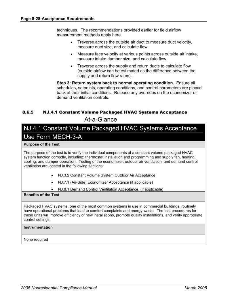
Page 8-28-Acceptance Requirements
2005 Nonresidential Compliance Manual March 2005
techniques. The recommendations provided earlier for field airflow measurement methods apply here.
• Traverse across the outside air duct to measure duct velocity, measure duct size, and calculate flow.
• Measure face velocity at various points across outside air intake, measure intake damper size, and calculate flow.
• Traverse across the supply and return ducts to calculate flow (outside airflow can be estimated as the difference between the supply and return flow rates).
Step 3: Return system back to normal operating condition. Ensure all schedules, setpoints, operating conditions, and control parameters are placed back at their initial conditions. Release any overrides on the economizer or demand ventilation controls.
8.6.5 NJ.4.1 Constant Volume Packaged HVAC Systems Acceptance
At-a-Glance NJ.4.1 Constant Volume Packaged HVAC Systems Acceptance Use Form MECH-3-A Purpose of the Test
The purpose of the test is to verify the individual components of a constant volume packaged HVAC system function correctly, including: thermostat installation and programming and supply fan, heating, cooling, and damper operation. Testing of the economizer, outdoor air ventilation, and demand control ventilation are located in the following sections:
• NJ.3.2 Constant Volume System Outdoor Air Acceptance
• NJ.7.1 (Air-Side) Economizer Acceptance (if applicable)
• NJ.8.1 Demand Control Ventilation Acceptance. (if applicable) Benefits of the Test
Packaged HVAC systems, one of the most common systems in use in commercial buildings, routinely have operational problems that lead to comfort complaints and energy waste. The test procedures for these units will improve efficiency of new installations, promote quality installations, and verify appropriate control settings.
Instrumentation
None required

Acceptance Requirements Page 8-29
2005 Nonresidential Compliance Manual March 2005
Test Conditions
Packaged unit and thermostat installation and programming must be complete.
HVAC system must be installed and ready for system operation, including completion of all start-up procedures, per manufacturer’s recommendations.
Document the initial conditions before overrides or manipulation of the setpoints and schedules. All systems must be returned to normal at the end of the test.
Time to Complete
Construction inspection: 0.5 to 1 hour (depending on familiarity with thermostat programming)
Equipment test: 1 to 2 hours
Acceptance Criteria
The thermostat is wired to the unit correctly (note this can be inferred from the acceptance tests).
The heating and cooling setpoints and schedules have been programmed into a thermostat or central DDC system. The heating and cooling setpoints can be adjusted to least 5°F apart.
Acceptance Criteria
The following modes of operation function correctly:
• Occupied heating mode operation: The supply fan operates continuously, all heating stages operate, cooling is not enabled, and the outdoor air damper is at minimum position.
• Occupied operation with no heating or cooling load: The supply fan operates continuously, heating or cooling are not enabled, and the outdoor air damper is at minimum position.
• Occupied cooling mode operation without economizer: The supply fan operates continuously, all cooling stages operate, heating is not enabled, and outside damper is at minimum position.
• Unoccupied operation with no heating or cooling load: The supply fan shuts off, heating or cooling are not enabled, and the outdoor air damper is closed.
• Unoccupied operation with heating load: The supply cycles ON, heating is enabled, cooling is not enabled, and the outdoor air damper is at minimum position.
• Unoccupied cooling mode operation without economizer: The supply cycles ON, cooling is enabled, heating is not enabled, and the outdoor air damper is at minimum position.
• Override mode: System reverts to occupied mode, the supply fan turns ON for duration of override, heating or cooling is enabled as necessary, outdoor air damper opens to minimum position.

Page 8-30-Acceptance Requirements
2005 Nonresidential Compliance Manual March 2005
Potential Issues and Cautions
• Ensure that the supply fan runs continuously in occupied mode and cycles appropriately in unoccupied mode. Cycling refers to the supply fan running only when heating or cooling is enabled.
• When testing the manual override, it may be necessary to adjust the length of the override period to minimize test time. Be sure to reset the override period back to the correct length of time.
• Overall test time may be reduced (especially for rooftop HVAC units controlled by thermostats) if two people perform the test - one to manipulate the thermostat while someone else verifies operation at the packaged unit.
• The Standards do not mandate the actual differential between occupied and unoccupied setpoints, only that the system must be adjustable down to 55°F for heating and up to 85°F for cooling and that the thermostat can be set for a 5°F deadband.
• Setback control is only required for climates where the winter median of extremes is less than or equal to 32°F.
• Setup control is only required for climates where the 0.5% summer design dry-bulb temperature is greater than or equal to 100°F.
8.6.6 Test Procedure: NJ.4.1 Constant Volume Packaged HVAC Systems Acceptance, Use Form MECH-3-A
Test Comments The following acceptance test procedures are applicable to systems controlled by individual thermostats, internal DDC, or central DDC systems. Most of the tests can be performed through simple manipulation of the individual thermostat or the DDC system controlling each packaged HVAC unit. Specific details and examples of how to perform each test are provided below.
Construction Inspection
Thermostat, or temperature sensor, is located within the zone that the HVAC system serves.
Thermostat is wired to the unit correctly. Note that this can be inferred from the acceptance tests.
1. In particular, ensure that multiple stage terminals (i.e., 1st and 2nd stage wires) on the thermostat, both cooling and heating stages, are wired to the corresponding circuits at the unit.
2. Verify that no factory-installed or field-installed jumpers exist across the 1st and 2nd stage cooling terminals at the unit (this will ensure that only the economizer can be enabled as the 1st stage of cooling).
3. For heat pump only, verify the “O” terminal on the thermostat is wired to the reversing valve at the unit.

Acceptance Requirements Page 8-31
2005 Nonresidential Compliance Manual March 2005
4. For heat pump only, verify thermostat dip switch or programmable software is set to heat pump.
Thermostat is capable of achieving a 5°F deadband between heating and cooling setpoints.
Setup and setback (unoccupied) setpoints have been enabled (if required).
Occupied, unoccupied, and holiday schedules have been programmed. Schedules are programmed into an individual thermostat or central DDC system. Note that some thermostat brands require that the thermostat be in the “program” mode of operation in order for time schedules to be enabled.
Pre-occupancy purge has been programmed per §121(c)2. This is most easily accomplished by scheduling the unit to start one hour prior to actual occupancy.
Equipment Testing The following procedures are applicable to systems controlled by a programmable thermostat, internal DDC (packaged systems only), or central DDC system.
Step 1: Simulate heating load during occupied condition. (Mode A on MECH-3-A form). • Set “occupied” time schedule to include actual time or adjust time to
be within the “occupied” time schedule (which ever is easier).
• Set heating setpoint above actual space temperature.
Verify and Document
• Supply fan operates continually during occupied condition.
• Ensure all available heating stages operate. This may require raising the heating setpoint even further so that multiple heating stages can become enabled. For example, many programmable thermostats and DDC control algorithms use time delays and deviation from setpoint to enable multiple heating stages. Setting the heating setpoint very high should prevent the 1st stage of heat from meeting setpoint and allow the system adequate time to enable the 2nd or 3rd stages.
• Cooling is not enabled.
• Outside air damper is open to minimum ventilation position (Note: Outdoor ventilation air requirements will be tested under section NJ.3.2 Constant Volume System Outdoor Air Acceptance).
Step 2: Simulate dead band operation during occupied condition. (Mode B)
• Set “occupied” time schedule to include actual time or adjust time to be within the “occupied” time schedule (which ever is easier).
• Adjust heating and cooling setpoints so that actual space temperature is between the two values.

Page 8-32-Acceptance Requirements
2005 Nonresidential Compliance Manual March 2005
Verify and Document
• Supply fan operates continually during occupied condition.
• Heating or cooling should not be enabled.
• Outside air damper is open to minimum ventilation position.
Step 3: For systems without an economizer, simulate cooling load during occupied condition. Mode F
• Set “occupied” time schedule to include actual time or adjust time to be within the “occupied” time schedule (which ever is easier).
• Set cooling setpoint below actual space temperature.
Verify and Document
• Supply fan operates continually during occupied condition.
• Ensure all available cooling stages operate. This may require lowering the cooling setpoint even further so that multiple cooling stages can become enabled. For example, many programmable thermostats and DDC control algorithms use time delays and deviation from setpoint to enable multiple cooling stages. Setting the cooling setpoint very low should prevent the 1st stage of cooling from meeting setpoint and allow the system adequate time to enable the 2nd stage.
• Heating is not enabled.
• Outside air damper is open to minimum ventilation position.
Step 4: Simulate dead band operation during unoccupied condition. Mode D
• Set “unoccupied” time schedule to include actual time or adjust time to be within the “unoccupied” time schedule (which ever is easier).
• Ensure actual space temperature is in between unoccupied heating and cooling setpoints. Adjust each setpoint as necessary to achieve desired control.
Verify and Document
• Supply fan shuts OFF during unoccupied condition.
• Neither heating or cooling is enabled.
• Outside air damper is completely shut.
Step 5: Simulate heating load during unoccupied condition.
Mode C Note: This test is only applicable for all systems in a climate where the design winter median of extremes is less than or equal to 32°F( that are not exempt by §122(e)2.A).
• Set “unoccupied” time schedule to include actual time or adjust time to be within the “unoccupied” time schedule (which ever is easier).

Acceptance Requirements Page 8-33
2005 Nonresidential Compliance Manual March 2005
• Set heating setpoint above actual space temperature.
Verify and Document
• Supply fan cycles on with call for heating.
• Heating is enabled.
• Cooling is not enabled.
Step 6: For systems without an economizer, simulate cooling load during unoccupied condition.
Mode G Note: systems with an economizer will be tested for proper system operation under a cooling load in section NJ.7.1 Economizer Acceptance. This test is only applicable for those systems in a climate where the 0.5% summer design dry-bulb temperature is greater than or equal to 100°F (other systems are exempted by §122(e)2.B).
• Set “unoccupied” time schedule to include actual time or adjust time to be within the “unoccupied” time schedule (which ever is easier).
• Set cooling setpoint above actual space temperature.
Verify and Document
• Supply fan cycles on with call for cooling.
• Heating is not enabled.
• Cooling is enabled.
• Outside air damper.
Step 7: Simulate manual override during unoccupied condition. Mode E • Set “unoccupied” time schedule to include actual time or adjust time
to be within the “unoccupied” time schedule (which ever is easier).
• Engage the manual override. This could entail pushing an override button, triggering an occupancy sensor, or enabling some other form of override control.
Verify and Document
• System reverts back to an “occupied” condition. For a DDC control system, verify the “active” heating and cooling setpoints correspond to those programmed for the occupied condition. For a programmable thermostat, the thermostat may display that it is in the “occupied” mode.
• Supply fan turns on and stays on for the duration of the timed override period.
• Heating or cooling is enabled as necessary to maintain space temperature setpoint. Actual operation of the equipment depends on whether heating or cooling is needed at the time of the test.

Page 8-34-Acceptance Requirements
2005 Nonresidential Compliance Manual March 2005
• Outside air damper opens to minimum ventilation position and remains open for the duration of the timed override period. If the system has an economizer and there is call for cooling during the manual override, then the economizer should be enabled as necessary.
• System reverts back to an “unoccupied” condition at the end of the timed override period. It may be necessary to adjust the length of the override period to minimize test time.
Step 8: For systems with an economizer, simulate cooling load during occupied condition (Mode H).
• Set “occupied” time schedule to include actual time or adjust time to be within the “occupied” time schedule (which ever is easier).
• Set cooling setpoint below actual space temperature.
Verify and Document
• Supply fan operates continually during occupied condition.
• Ensure all available cooling stages operate. This may require lowering the cooling setpoint even further so that multiple cooling stages can become enabled. For example, many programmable thermostats and DDC control algorithms use time delays and deviation from setpoint to enable multiple cooling stages. Setting the cooling setpoint very low should prevent the 1st stage of cooling from meeting setpoint and allow the system adequate time to enable the 2nd stage.
• Heating is not enabled
• System passes tests for economizer in NJ.7.1 Air-Side Economizer Acceptance and documented on form MECH-4-A.
Step 9: For systems with an economizer, simulate cooling load during unoccupied condition (Mode I).
• Set “unoccupied” time schedule to include actual time or adjust time to be within the “unoccupied” time schedule (which ever is easier).
• Set cooling setpoint above actual space temperature.
Verify and Document
• Supply fan cycles on with call for cooling.
• Heating is not enabled.
• Cooling is enabled.
• Outside air damper is closed.
• System passes tests for economizer in NJ.7.1 Air-Side Economizer Acceptance and documented on form MECH-4-A.

Acceptance Requirements Page 8-35
2005 Nonresidential Compliance Manual March 2005
Step 10: Return system back to normal operating condition. Ensure all schedules, setpoints, operating conditions, and control parameters are placed back at their initial conditions.
8.6.7 NJ.7.1 Air-Side Economizer Acceptance
At-a-Glance NJ.7.1 (Air-Side) Economizer Acceptance Use Form MECH-4-A Purpose of the Test
The purpose of functionally testing an air-side economizer cycle is to verify that an HVAC system uses outside air to satisfy space cooling loads when outside air conditions are acceptable. There are two types of economizer controls:
• stand-alone packages and DDC controls. The stand-alone packages are commonly associated with rooftop packaged HVAC equipment and DDC controls are typically associated with built-up or large packaged air handling systems. Test procedures for both economizer control types are provided.
For units with economizers that are factory installed and certified operational by the manufacturer to California Energy Commission economizer quality control requirements, the in field economizer acceptance test does not have to be conducted. A copy of the certification certificate must be attached to the MECH-4-A. All pre-test inspections must be completed regardless of whether the economizer is factory or field installed.
Benefits of the Test
Ensuring that the economizer fully utilizes outside air for “free cooling” can save significant cooling energy compared to operating mechanical refrigeration.
Provision and control of building relief prevents building over pressurization which is a common reason for economizers being disabled by building operators.
Since an economizer cycle will bring in outdoor air beyond what is required for ventilation purposes, it will improve building indoor air quality.
Instrumentation
None required

Page 8-36-Acceptance Requirements
2005 Nonresidential Compliance Manual March 2005
Test Conditions
Equipment installation is complete (including HVAC unit, duct work, sensors, control system, thermostats).
Simple systems are required to have a two-stage thermostat.
HVAC system must be ready for system operation, including completion of all start-up procedures per manufacturer’s recommendations.
For those units having DDC controls, it may be necessary to use the building automation system (BAS) to override or temporarily modify the variable(s) to achieve the desired control. BAS programming for the economizer, cooling valve control, and related safeties must be complete.
For built-up systems all interlocks and safeties must be operable--for example, freeze protection, limit switches, static pressure cut-out, etc.
Document the initial conditions before overrides or manipulation of the settings. All systems must be returned to normal at the end of the test.
Time to Complete
Construction Inspection: 0.5 to 1 hours (depending on familiarity with the controls)
Equipment Testing: 0.5 to 2 hours (depending on familiarity with the controls and issues that arise during testing)
Acceptance Criteria
If the economizer is factory installed and certified, a valid factory certificate is required for acceptance. No additional equipment tests are necessary.
Air-Side Economizer lockout setpoint complies with Table 144-C per Standards Section 144(e)3. Outside sensor location accurately reads true outdoor air temperature and is not affected by exhaust air or other heat sources.
All sensors are located appropriately to achieve the desired control.
During economizer mode, the outside air damper modulates open to a maximum position and return air damper modulates 100% closed.
The outside air damper is 100% open before mechanical cooling is enabled and for units 75,000 Btuh and larger remains at 100% open while mechanical cooling is enabled (economizer integration when used for compliance).
When the economizer is disabled, the outside air damper closes to a minimum position, the return damper modulates 100% open, and mechanical cooling remains enabled.

Acceptance Requirements Page 8-37
2005 Nonresidential Compliance Manual March 2005
Potential Issues and Cautions
If conditions are below freezing when test is performed, coil(s) may freeze when operating at 100% outside air.
Outdoor air and relief dampers should be closed when the system is in unoccupied and warm-up modes, preventing problems with unconditioned air entering the building during unoccupied hours.
If the damper interlocks fail and the outdoor air damper does not open before the return damper closes, damage to the air handling unit or associated duct work may occur.
Air-Side Economizers with poor mixing can have excessively stratified air streams that can cause comfort problems or freezestat trips. Mixing problems are more likely to occur as the VAV system reduces flow, leading to reduced velocities in the mixing box and through the dampers.
Check for exterior doors standing open and other signs of building over-pressurization when all units are on full economizer cooling (100% OSA).
8.6.8 Test Procedure: NJ.7.1 Air-Side Economizer Acceptance, Use Form MECH-4-A
Purpose (Intent) of Test There are basically two types of economizer controls: 1) stand-alone packages (i.e. Honeywell W7459A, Trane Precedent or Voyager, Carrier Durablade, which are most common); and 2) DDC controls. The stand-alone packages are most commonly associated with rooftop packaged HVAC equipment and DDC controls are typically associated with built-up or large packaged air handling systems. Test procedures for both economizer control types have been developed and a brief description of each control strategy is provided below.
If the economizer is factory installed and certified by the manufacturer to the California Energy Commission, no field testing is required.
The typical economizer control will have the following components: a controller (stand alone or DDC); an actuator that will drive both outside and return air dampers (sometimes separate actuators in built-up systems); an outside air sensor; a return air sensor where differential high-limit controls are used; and a mixed/discharge air temperature sensor to which the economizer is controlled. The sensor types used to measure outside and return air include dry-bulb temperature sensors, enthalpy sensors, and electronic enthalpy sensors (a combination of dry-bulb and enthalpy).
In general, a first-stage call for cooling from the zone thermostat will enable the economizer controller, which will either allow the outside air damper to open fully if outside air conditions are suitable or enable the compressor. The four strategies available for economizer control are: 1) fixed dry-bulb; 2) fixed enthalpy; 3) differential dry-bulb; and 4) differential enthalpy. The fixed dry-bulb and enthalpy strategies both compare outside air conditions to a “fixed” setpoint to determine if the economizer can be enabled, whereas differential dry-bulb and enthalpy strategies compares outside air and return air conditions to enable
Page 8-38-Acceptance Requirements
2005 Nonresidential Compliance Manual March 2005
the economizer when outside air conditions are more favorable. When the zone thermostat calls for a second-stage of cooling, the compressor is enabled to provide mechanical cooling. The economizer is considered integrated if the economizer can operate simultaneously with the compressor or chilled water coil. If the controls disable the economizer when the compressor (or chilled water coil) is on, it is considered non-integrated. Where economizers are required by the Standards, they must have integrated controls.
Construction Inspection Air-Side Economizer high temperature lockout setpoint complies with Standards Table 144-C per §144(e)3. For DDC control systems, the lockout setpoint should be a control parameter in the sequence of operations that can be verified for compliance. For stand-alone packages, the lockout setpoint is determined by settings on the controller (for example A, B, C, D settings on the Honeywell W7459A controller or dip switches on a Trane control package). Consult with manufacturer’s literature to determine the appropriate A, B, C, D or dip switch settings. Note that snap disks may not comply with lockout requirements in some climate zones. A snap disk is a thermostat-type control device with a fixed setpoint. The snap disk will close the economizer circuit when air temperature is below setpoint and open the circuit when the air temperature exceeds setpoint. Snap disks are not adjustable and can disable the economizer anywhere between 65°F and 70°F. Hence, snap disks will fail unless the manufacturer can provide documentation verifying the snap disk operating temperature complies with Standards Table 144-C. The control complies if the high limit lockout setpoint is less than the values specified in the table.

Acceptance Requirements Page 8-39
2005 Nonresidential Compliance Manual March 2005
Table 8-4 – Standards Table 144-C Air Economizer High Limit Shut Off Control Requirements
Device Type Climate Zones Required High Limit (Economizer Off When): Equation Description Fixed Dry Bulb 1, 2, 3, 5, 11, 13, 14, 15 & 16 TOA > 75ºF Outside air temperature
exceeds 75ºF
4, 6, 7, 8, 9, 10 & 12 TOA > 70ºF Outside air temperature exceeds 70°F
Differential Dry Bulb All TOA > TRA Outside air temperature exceeds return air
temperature Fixed Enthalpya 4, 6, 7, 8, 9, 10 & 12 hOA > 28 Btu/lbb Outside air enthalpy exceeds
28 Btu/lb of dry airb Electronic Enthalpy All (TOA, RHOA) > A Outside air temperature/RH
exceeds the "A" set-point curvec
Differential Enthalpy All hOA > hRA Outside air enthalpy exceeds return air enthalpy
a Fixed Enthalpy Controls are prohibited in climate zones 1, 2, 3, 5, 11, 13, 14, 15 & 16. b At altitudes substantially different than sea level, the Fixed Enthalpy limit value shall be set to the enthalpy value at 75�F and 50% relative humidity. As an example, at approximately 6000 foot elevation the fixed enthalpy limit is approximately 30.7 Btu/lb. c Set point "A" corresponds to a curve on the psychometric chart that goes through a point at approximately 75�F and 40% relative humidity and is nearly parallel to dry bulb lines at low humidity levels and nearly parallel to enthalpy lines at high humidity levels.
• For stand-alone packages only, verify that a two-stage thermostat is used, and that the system is wired so that the economizer is the first stage of cooling and the compressor is the second stage. The two-stage space thermostat must have wires connected to Y1 and Y2 on the thermostat landed on the respective Y1 and Y2 terminals at the unit. There should not be any jumpers installed across Y1 and Y2 at the thermostat or the unit. For York units in particular, verify that the “J1” jumper located on the OEM board has been removed. The units come from the factory with the “J1” jumper installed and must be removed in the field (the “J1” jumper is the same as having a jumper across the Y1 and Y2 terminals – the compressor and economizer come on simultaneously on a call for cooling, which effectively makes the economizer inoperable). Note that if a single-stage thermostat is installed, there should not be any jumper between Y1 and Y2.
• Air-Side Economizer outside (lockout) sensor location is adequate to achieve the desired control. Outside air sensors should be located away from building exhausts and other heat sources like air-cooled condensers and cooling towers; should be open to the air but not exposed to direct sunlight (unless it is provided with a radiation shield); and could be located either directly in the air stream or remote from the unit (for example mounted on a north-facing wall).
• Ensure all systems have some method of relief to prevent over pressurization of the building. Most packaged HVAC units with stand-alone economizer controls will typically have barometric

Page 8-40-Acceptance Requirements
2005 Nonresidential Compliance Manual March 2005
dampers to exhaust the return air when the return dampers are fully closed and the unit is in economizer mode. Built-up and larger packaged air handling units may control return fans, relief dampers, or dedicated relief fans to actively maintain building pressurization when the unit is in economizer mode.
Equipment Testing Since the test procedures vary significantly between stand-alone packages and DDC controls, the procedures for each system type are provided. In addition, there can be significant differences in test procedures between various stand-alone packages themselves. Contact your equipment supplier to see if they have equipment and test protocols that will allow you to easily field test their economizer to ACM NJ.7.1 Air-Side Economizer Acceptance for filling out form MECH-4-A. While it would not be feasible to cover every variation, three of the most common stand-alone packages are discussed below. The common feature of these procedures is that they all exercise the economizer function either by enabling an on-board diagnostic function or by “fooling” the control by inserting resistors that simulate mild weather conditions while the system is in cooling mode.
Stand-alone Package
Trane Voyager and Precedent Series. Both of these control packages have internal test sequences that can be used to verify proper system operation. Each operating mode is enabled by providing a momentary (2 second) jump across the test terminals.
Step 1. Use internal test sequences to enable operating modes. Refer to manufacturer’s literature for detailed description of the procedures, however the basic steps are outlined below:
• 1st jumper – supply fan is enabled
• 2nd jumper – economizer mode is enabled
• 3rd jumper – compressor is enabled
• 4th jumper – heating stage is enabled
Verify and Document
• Outside air damper is at minimum position when the supply fan is enabled.
• The outside air damper opens completely and the return damper closes completely during economizer mode.
• Outside air damper is at minimum position when the compressor is enabled.
• Outside air damper is at minimum position when heating is enabled.
• Verify the mixed/discharge cut-out sensor wire is landed on the SA terminal on the OEM board. If the sensor wire is not landed on the SA terminal, the economizer will not operate.
Acceptance Requirements Page 8-41
2005 Nonresidential Compliance Manual March 2005
Step 2. Return system to normal operation. Taking the system out of test mode can be accomplished by shutting power off to the unit. The unit will return to normal operation when power is restored.
Verify and Document
• Final economizer changeover dip-switch settings comply with Standards Table 144-C per §144(e)3.
Honeywell controllers. There are many Honeywell controllers available, but the most common is the W7459A series and most of the procedures used to check out this controller can be used on the others as well (always refer to manufacturer’s literature for additional information). All Honeywell controllers have an adjustment pot with “A, B, C, D” settings. For a fixed changeover strategy, the position of the adjustment pot with respect to the A, B, C, D settings will determine the economizer lockout setpoint. For a differential changeover strategy, the controller should be on the “D” setting. Note that the controllers typically come from the factory with the adjustment pot at the “D” setting, but this does not mean a differential control strategy is being used. The easiest way to verify a differential changeover strategy is to look at the SR and + terminals on the controller. If standard sensor wires are connected to the terminals, then it is a differential control strategy. If there is a 620 Ohm resister jumpered across these terminals, then a fixed control strategy is being used.
Step 1. Simulate a cooling load and enable the economizer. The simplest way to determine if the controller is functioning is to:
• Turn the unit OFF at the disconnect.
• Install a 1.2K Ohm resister across the SO and + terminals on the controller (this is the outside air temperature sensor).
• Install a 620 Ohm resister across the SR and + terminals on the controller (this resister is already installed for a fixed control strategy and must only be installed if there is a return air sensor).
• Turn the economizer setpoint adjustment pot all the way to the “A” setting.
• Install a jumper across the R and Y1 terminals at the unit terminal strip.
• Disconnect the wire from the Y2 terminal at the unit terminal strip (this will prevent the 2nd stage of cooling from being enabled during the test).
• Turn the unit back ON at the disconnect.
Verify and Document
• Outside air dampers open fully. Adjust linkages, if necessary, to ensure dampers are at the desired position.
• Return air dampers close completely. Adjust linkages, if necessary, to ensure dampers are at the desired position.

Page 8-42-Acceptance Requirements
2005 Nonresidential Compliance Manual March 2005
• Compressor does not run.
Step 2. Simulate a cooling load and disable the economizer. Continuing from above:
• Turn the unit OFF at the disconnect.
• Leave the 1.2K Ohm resister across the SO and + terminals and 620 Ohm resister across the SR and + terminals in place.
• Turn the economizer setpoint adjustment pot all the way to the “D” setting.
• Leave jumper across the R and Y1 terminals at the unit terminal strip.
• Leave Y2 disconnected.
• Turn the unit back ON at the disconnect.
Verify and Document
• Outside air dampers close to minimum position. Adjust linkages, if necessary, to ensure dampers are at the desired position.
• Return air dampers open completely. Adjust linkages, if necessary, to ensure dampers are at the desired position.
• Compressor operates.
Step 3: Return system back to normal operating condition. Remove all jumpers and reconnect all wires.
Verify and Document
• Final economizer changeover setting (A,B,C,D) complies with Standards Table 144-C per §144(e)3. Consult with manufacturer’s literature to determine the appropriate A, B, C, D setting for both fixed dry-bulb or enthalpy control strategies. The controller must be set on “D” for all differential control strategies.
Carrier Durablade. Most Carrier HVAC units utilize the “Durablade” economizer control package, which uses a single damper “blade” that slides on a worm gear across both the outside and return air streams. Blade position is determined by end-switches that will cut power to the drive-motor when desired damper position is reached. Typically the economizer will be controlled by either a fixed dry-bulb or fixed enthalpy control strategy. Enthalpy control typically utilizes a customized Honeywell controller and the checkout procedures outlined above can be used to determine economizer functionality. The following test procedures should be followed for a fixed dry-bulb strategy.
Step 1. Simulate a cooling load and enable the economizer. The simplest way to determine if the economizer is functioning is to:
• Turn the unit OFF at the disconnect.
• Install a jumper across the outside air temperature thermostat.

Acceptance Requirements Page 8-43
2005 Nonresidential Compliance Manual March 2005
• Install a jumper across the R and Y1 terminals at the unit terminal strip.
• Disconnect the wire from the Y2 terminal at the unit terminal strip (this will prevent the 2nd stage of cooling from being enabled during the test).
• Turn the unit back ON at the disconnect.
Verify and Document
• Damper blade slides completely across the return air duct and mixed air plenum is open to the outside air intake. Adjust end-switches as necessary to achieve the desired position.
• Compressor does not run.
Step 2. Simulate a cooling load and disable the economizer. Continuing from above:
• Turn the unit OFF at the disconnect.
• Remove the jumper and disconnect the outside air sensor completely from the circuit.
• Leave Y2 disconnected.
• Turn the unit back ON at the disconnect.
Verify and Document
• Damper blade returns to minimum outside air position. Adjust end switches as necessary to achieve the desired position.
• Compressor operates.
Step 3: Return system back to normal operating condition. Remove all jumpers and reconnect all wires.
Verify and Document
• Final economizer changeover setting complies with Standards Table 144-C per §144(e)3.
DDC Controls
Step 1. Simulate a cooling load and enable the economizer. Simulating a cooling load and enabling the economizer can be accomplished by:
• Commanding the discharge air temperature setpoint to be lower than current discharge conditions.
• For a fixed dry-bulb or enthalpy control strategy, raising the economizer lockout setpoint to be above current outside air conditions (if this is not the case already) to enable the economizer.

Page 8-44-Acceptance Requirements
2005 Nonresidential Compliance Manual March 2005
• For a differential dry-bulb or enthalpy control strategy; raising the return air conditions to be above current outside air conditions (if this is not the case already) to enable the economizer.
Verify and Document
• Outside air damper modulates open to a maximum position.
• Return air damper modulates closed and is 100% closed when the outside air dampers are 100% open. Return dampers should close tight to minimize leakage.
• Outside air damper is 100% open before mechanical cooling is enabled. This implies that cooling coil valves in chilled water systems should not modulate or compressors in DX systems should not start until the unit is in 100% economizer mode. Depending on the speed of the PID loop, it is possible that mechanical cooling could be commanded on before the outside air dampers actually stroke fully open. If this occurs, it does not mean the system has failed the test. One option is to watch the output of the PID loop and verify that the COMMAND sent to the outside air damper reaches 100% before a command is sent to the mechanical cooling devices.
• Although space pressurization requirements are not part of the current Standards, most systems employ some form of control strategy to maintain space pressure during economizer mode. Control strategies can include, but are not limited to: 1) return fan speed control; 2) dedicated relief fans; or 3) relief damper controls. Observe that the space served by the air handling unit being tested does not appear to experience any pressurization problems (i.e., perimeter doors pushed open or excessive airflow between zones served by different units).
Step 2. Simulate a cooling load and disable the economizer. Continuing from the procedures outlined in Step 1:
• Keep the discharge air temperature setpoint lower than current discharge conditions.
• For a fixed dry-bulb or enthalpy control strategy, lower the economizer lockout setpoint to be below current outside air conditions (if this is not the case already) to disable the economizer.
• For a differential dry-bulb or enthalpy control strategy; lower the return air conditions to be below current outside air conditions (if this is not the case already) to disable the economizer.
Verify and Document
• Outside air damper closes to a minimum position.
• Return air damper opens to normal operating position when the system is not in economizer mode.

Acceptance Requirements Page 8-45
2005 Nonresidential Compliance Manual March 2005
• Mechanical cooling remains enabled to satisfy discharge air temperature setpoint.
Step 3: Return system back to normal operating condition. Ensure all schedules, setpoints, operating conditions, and control parameters are placed back at their initial conditions.

Page 8-46-Acceptance Requirements
2005 Nonresidential Compliance Manual March 2005
8.6.9 NJ.5.1 Air Distribution Acceptance
At-a-Glance NJ.5.1 Air Distribution Acceptance Use Form MECH-5-A Purpose of the Test
The purpose of this test is to verify all duct work associated with all non-exempt constant volume, single-zone, HVAC units (i.e. air conditioners, heat pumps, and furnaces) meet the material, installation, and insulation R-values per §124(a) requirements of §144(k), including construction materials, installation, insulation R-values, and that duct leakage does not exceed the maximum allowable leakage fraction per §144(k) for new duct systems or §149(b)1D for existing duct systems.
As detailed in the Standard this test is only required for single-zone units serving 5,000 ft2 of space or less where 25% or more of the duct surface area is in one of the following spaces:
• Outdoors, or
• In a space directly under a roof where the U-factor of the roof is greater than the U-factor of the ceiling, or
• In a space directly under a roof with fixed vents or openings to the outside or unconditioned spaces, or
• In an unconditioned crawlspace; or
• In other unconditioned spaces.
Within this criteria, this test applies to both new duct systems and to existing duct systems which are either being extended or the space conditioning system is altered by the installation or replacement of space conditioning equipment including: replacement of the air handler; outdoor condensing unit of a split system air conditioner or heat pump; cooling or heating coil; or the furnace heat exchanger. Existing duct systems do not have to be tested if they are insulated or sealed with asbestos.
Benefits of the Test
Duct construction and insulation can have adverse impacts on energy usage and duct-system durability. These are most acute where the ducts are located in unconditioned spaces or out of doors.
Instrumentation
Performance of this test will require measuring airflow. Equipment used:
• Fan flowmeter (a fan with a calibrated orifice used to pressurize the ducts) accuracy within 3% of measured flow. Contact CHEERS or CalCerts for proper equipment.
• Digital manometer (pressure meter) accuracy within 0.2 Pascals.
Duct leakage tests must be verified by a certified HERS rating agency certified by the California Energy Commission. There are currently two company’s that certify HEERS raters. They can be found at http://www.CHEERS.org or http://www.CalCerts.com

Acceptance Requirements Page 8-47
2005 Nonresidential Compliance Manual March 2005
Test Conditions
For new construction all ductwork must be accessible for visual inspection. Hence, visual inspection must be performed before ceiling is installed.
All ductwork and grilles should be in place before performing the fan flow test to ensure system depicts normal operating configuration. Hence, testing must occur after visual inspection and installation of the diffusers.
HVAC system must be installed and ready for system operation, including completion of all start-up procedures, per manufacturer’s recommendations.
Time to Complete
Construction Inspection: 0.5 to 2 hours (depending on duct access for visual inspections and availability of construction material documentation – i.e. cut sheets, etc.)
Equipment Test: 3 to 6 hours (depending on how long it takes to seal all supply diffusers and return grills and whether total system airflow is measured rather than calculated)
Acceptance Criteria
Flexible ducts are not constricted in any way.
Drawbands are either stainless steel worm-drive hose clamps or UV-resistant nylon duct ties. Joints and seams are not sealed with a cloth-back rubber adhesive tape unless used in combination with mastic and drawbands.
Duct R-values comply with Standards and insulation is protected from damage per Standards.
For new duct systems, the leakage fraction for the HVAC duct system does not exceed 6%, where the leakage fraction is calculated by dividing total measured leakage flow rate by the total fan system flow rate.
For existing duct systems (covered by Standard Sections 149b1(D or E), the leakage fraction for the HVAC duct system does not exceed either 15% or leakage is reduced by a 60% The leakage fraction is calculated by dividing total measured leakage flow rate by the total fan system flow rate.
Duct installation, insulation and leakage verified by a Home Energy Rating System (HERS) rater.
Potential Issues and Cautions
If this test is to be applied to existing duct systems that are having alterations made to the ducts or the HVAC equipment attached to the ducts, test the system leakage before making the alterations.
Ensure all of the supply and return diffusers/grills are sealed tightly, all access panels are in place, and duct ends are sealed tightly prior to leakage testing.
After the test, remember to remove all blockages from the supply and return ducts (i.e., where the supply and return ducts at the HVAC unit were blanked off). Seal any holes drilled in the supply and return ducts for the static pressure probes.
Since a certified California HERS rater must also verify duct leakage performance, it may be prudent to coordinate this test with the HERS rater so that the HERS rater can witness/verify the test simultaneously.

Page 8-48-Acceptance Requirements
2005 Nonresidential Compliance Manual March 2005
8.6.10 Test Procedure: NJ.5.1 Air Distribution Acceptance, Use Form MECH-5-A
Scope of the Requirements This test only applies to single-zone units serving 5,000 ft2 of space or less where 25% or more of the duct surface area is in one of the following spaces:
• Outdoors, or
• In a space directly under a roof where the U-factor of the roof is greater than the U-factor of the ceiling, or
• In a space directly under a roof with fixed vents or openings to the outside or unconditioned spaces, or
• In an unconditioned crawlspace; or
• In other unconditioned spaces
Within this criteria, this test applies to both new duct systems and to existing duct systems which are either being extended or the space conditioning system is altered by the installation or replacement of space conditioning equipment including: replacement of the air handler; outdoor condensing unit of a split system air conditioner or heat pump; cooling or heating coil; or the furnace heat exchanger. Existing duct systems do not have to be tested if they are insulated or sealed with asbestos.
Purpose (Intent) of Test The duct work of these small single-zone systems with ducts in unconditioned spaces must meet the requirements of §144(k) for duct leakage and new duct systems must meet the requirements of §124 including construction materials, installation, and insulation R-values.
Construction Inspection The first component of the construction inspection is to assure that the duct system falls under the scope this test (see above Scope of the Requirements). Most of the rest of the construction inspection applies to new duct systems. For existing duct system the purpose of this test is to assure the ducts do not leak excessively and do not require that existing ducts have to be brought up to current standards in terms of insulation, or requirements for fasteners. Perform a brief review of the drawings and construction to verify that the following items are specified in the construction set and installed in the field. A comprehensive review of each duct is not required.
• Drawbands are either stainless steel worm-drive hose clamps or UV-resistant nylon duct ties. Verify compliance by reviewing material cut sheets and visual inspection.
• Flexible ducts are not constricted in any way. For example, ensure the flex duct is not compressed against immovable objects, squeezed through openings, or contorted into extreme configurations (i.e., 180° angles). Flex duct that is constricted can increase system static pressure as well as compromise insulation values. Verify compliance through visual inspection.

Acceptance Requirements Page 8-49
2005 Nonresidential Compliance Manual March 2005
• Duct leakage tests shall be performed before access to ductwork and associated connections are blocked by permanently installed construction material. The intent here is to ensure construction modifications can be made, if necessary, before access to the ductwork is restricted.
• Joints and seams are not sealed with a cloth-back rubber adhesive tape unless used in combination with mastic and drawbands. Verify compliance through visual inspection.
• Duct R-values are verified. Duct insulation R-value shall comply with §124(a), 124(c), and 124(d), and can be verified by reviewing material cut sheets and through visual inspection.
• Insulation is protected from damage per §124(f). Verify compliance by reviewing material cut sheets and through visual inspection.
Equipment Testing Refer to the Scope section above for where this test is required. Where it is required the test will often be conducted by the installer and verified by a HERS rater using the procedures outlined in the Nonresidential ACM Manual, Appendix NG, Section 4.3.8.2 and documented on compliance form, MECH-5-A.
The primary metric calculated is the leakage fraction of total fan flow. Total fan flow is based on the cooling capacity of heating and cooling equipment and based on the heating capacity of heating only equipment. Total fan flow is determined to be 400 cfm/ton for cooling or heating and cooling equipment where a ton of cooling capacity is equal to 12 kBtu/h of cooling capacity. . For heating only equipment, total fan flow is 21.77 cfm per kBtu. The cooling and heating capacity of equipment can be found on the product nameplate.
For new duct systems, the installer blocks off all of the supply and return registers or diffusers and pressurizes the ducts with a fan flowmeter to 25 Pascals (Pa) and records the leakage airflow measured by the fan flowmeter. This leakage amount at 25 Pa is divided by the total fan flow for the leakage percentage. If this leakage percentage is less than or equal to 6%, the system passes. If the system does not pass, then the installer should look of all accessible leaks and seal any gaps. It is easier to find leaks with the ducts pressurized as one can often feel the air escaping from larger gaps.
For existing duct systems that are having additional ducts added or are having major repairs or replacement of equipment connected to the ducts, the leakage rate of the existing duct system should be tested first before any alterations proceed. This leakage amount is the Pre-test leakage value. After the additional ducts or equipment repairs or replacements conducted, then the ducts are sealed along any fittings or joints. After blocking off all supply and return registers or diffusers, the ducts are then pressurized using a fan flowmeter to 25 Pascals (Pa) and the fan flowmeter measures the final test leakage rate at 25 Pa. This final test leakage amount at 25 Pa is divided by the total fan flow for the leakage percentage. If this leakage percentage is less than or equal to 15%, the system passes. If the system does not pass, then the installer should look of all accessible leaks and seal any gaps. It is easier to find leaks with the ducts pressurized as one can often feel the air escaping from larger gaps.
Page 8-50-Acceptance Requirements
2005 Nonresidential Compliance Manual March 2005
If after all accessible leaks are sealed, the leakage percentage is still above 15%, the installer has two options:
If the final test leakage is 60% lower than the pre-test leakage rate and a visual inspection finds no accessible leaks, crushed ducts, animal infestation, rusted ducts etc., this will be sufficient to pass this requirement.
If the system meets neither the 15% leakage percentage nor was it possible to reduce the pre-tested leakage value by 60%, then the system must pass a visual inspection by a HERS rater. Unlike the other methods of compliance this method cannot be sampled – every system must be inspected by the HERS rater.
After completing the air distribution acceptance test, the installer shall affix a sticker to the air handler access door describing if the system met the prescriptive leakage requirements (6% leakage for new systems and 15% for existing systems or if the system) or if the system failed to meet this standard but that all accessible leaks were sealed. The installer supplies thee stickers and can have their company logo on them. However, the following information must be on the sticker in 14 pt font or larger.
Document management After conducting the air distribution acceptance test, the installer will contact the HERS rater so that the results can be validated. The Construction Inspection and the Installer Certification portion of MECH-5-A will be sent to the HERS Provider, the Builder (General Contractor or Construction Manager), the Building Owner at Occupancy and the Building Department.
The HERS rater will validate the results by filling out the HERS Rater Compliance Statement portion of MECH-5-A and send copies to the Builder (General Contractor or Construction Manager), the Building Owner at Occupancy and the Building Department. If the test complies by virtue of the tested leakage (6% for new ducts and 15% for existing ducts) or by virtue of a 60% leakage reduction before the system was repaired or altered, the HERS rater will sample ducts system by installer, having only to sample every one out of seven systems. For existing duct systems that fail both the 15% leakage rate and the 60% reduction in leakage, the HERS rater will validate all of these systems (100% sampling) by visual inspection.
Reference material from ACM Manual Appendix NJ Below are excerpts of air distribution acceptance testing requirements from ACM Manual Appendix NG Standard Procedure for Determining the Energy Efficiencies of Single-Zone Nonresidential Air Distribution Systems in Buffer Spaces or Outdoors
NG.4.1 Instrumentation Specifications
The instrumentation for the air distribution diagnostic measurements shall conform to the following specifications:

Acceptance Requirements Page 8-51
2005 Nonresidential Compliance Manual March 2005
NG.4.1.1 Pressure Measurements
All pressure measurements shall be measured with measurement systems (i.e. sensor plus data acquisition system) having an accuracy of ± 0.2 Pa. All pressure measurements within the duct system shall be made with static pressure probes.
NG.4.1.2 Duct Leakage Measurements
The measurement of air flows during duct leakage testing shall have an accuracy of ±3% of measured flow using digital gauges.
All instrumentation used for duct leakage diagnostic measurements shall be calibrated according to the manufacturer’s calibration procedure to conform to the above accuracy requirement. All testers performing diagnostic tests shall obtain evidence from the manufacturer that the equipment meets the accuracy specifications. The evidence shall include equipment model, serial number, the name and signature of the person of the test laboratory verifying the accuracy, and the instrument accuracy. All diagnostic testing equipment is subject to re-calibration when the period of the manufacturer’s guaranteed accuracy expires.
NG.4.2 Apparatus
NG.4.2.1 Duct Pressurization
California Air Distribution Acceptance (Duct Leakage) Certification
"The leakage of the air distribution ducts was found to be ___CFM @ 25 Pascals or ___% of total fan flow.
This system (check one):
Has a leakage rate that is equal to or lower than the prescriptive requirement of 6% leakage for new duct systems or 15% leakage for alterations to existing systems. It meets the prescriptive requirements of California Title 24 Energy Efficiency Standards.
Has a leakage rate higher than 6% leakage for new duct systems or 15% leakage for altered existing systems. It does NOT meet the meet or exceed the prescriptive requirements of the Title 24 standards. However, all accessible ducts were sealed.
Signed: ___________________
Print name: _____________________
Print Company Name:____________________
Print Contractor License No:_________________
Print Contractor Phone No:__________________
Do not remove sticker

Page 8-52-Acceptance Requirements
2005 Nonresidential Compliance Manual March 2005
The apparatus for fan pressurization duct leakage measurements shall consist of a duct pressurization and flow measurement device meeting the specifications in Section NG.4.1.2.
NG.4.3.7 Total Fan Flow
The total fan flow for an air conditioner or a heat pump for all climate zones shall be equal to 400 cfm/rated ton with rated tons defined by unit scheduled capacity at the conditions the unit’s ARI rating standard from Section 112 of the Standard. Airflow through heating only furnaces shall be based on 21.7 cfm/kBtuh rated output capacity.
NG.4.3.8.2 Diagnostic Duct Leakage
Diagnostic duct leakage measurement is used by installers and raters to verify that total leakage meets the criteria for any sealed duct system specified in the compliance documents. Table NG-3 shows the leakage criteria and test procedures that may be used to demonstrate compliance. In addition to the minimum tests shown, existing duct systems may be tested to show they comply with the criteria for new duct systems.
Table 8-5 – NG-3 Duct Leakage Tests
Case User and Application Leakage criteria, % of total fan flow Procedure
Sealed and tested new duct systems
Installer Testing HERS Rater Testing
6% NG 4.3.8.2.1
Sealed and tested altered existing duct systems
Installer Testing HERS Rater Testing
15% Total Duct Leakage NG 4.3.8.2.1
Installer Testing and Inspection HERS Rater Testing and Verification
60% Reduction in Leakage and Visual Inspection
NG 4.3.8.2.2 RC4.3.6 and RC4.3.7
Installer Testing and Inspection HERS Rater Testing and Verification
Fails Leakage Test but All Accessible Ducts are Sealed And Visual Inspection
NG 4.3.8.2.3 RC4.3.6 and RC4.3.7
NG.4.3.8.2.1 Total Duct Leakage Test from Fan Pressurization of Ducts
The objective of this procedure is for an installer to determine or a rater to verify the total leakage of a new or altered duct system. The total duct leakage shall be determined by pressurizing both the supply and return ducts to 25 Pascals with all ceiling diffusers/grilles and HVAC equipment installed. When existing ducts are to be altered, this test shall be performed prior to and after duct sealing. The following procedure shall be used for the fan pressurization tests:
• Verify that the air handler, supply and return plenums and all the connectors, transition pieces, duct boots and registers are installed. The entire system shall be included in the test.

Acceptance Requirements Page 8-53
2005 Nonresidential Compliance Manual March 2005
• For newly installed or altered ducts, verify that cloth backed rubber adhesive duct tape has not been used.
• Seal all the supply and return registers, except for one return register or the system fan access. Verify that all outside air dampers and /or economizers are sealed prior to pressurizing the system.
• Attach the fan flowmeter device to the duct system at the unsealed register or access door.
• Install a static pressure probe at a supply.
• Adjust the fan flowmeter to produce a 25 Pascal (0.1 in water) pressure difference between the supply duct and the outside or the building space with the entry door open to the outside.
• Record the flow through the flowmeter (Qtotal,25) - this is the total duct leakage flow at 25 Pascals.
• Divide the leakage flow by the total fan flow and convert to a percentage. If the leakage flow percentage is less than 6% for new duct systems or less than 15% for altered duct systems, the system passes.
• Duct systems that have passed this total leakage test will be sampled by a HERS rater to show compliance.
NG 4.3.8.2.2 Leakage Improvement from Fan Pressurization of Ducts
For altered existing duct systems which have a higher leakage percentage than the Total Duct leakage criteria in Section NG 4.3.8.2.1, the objective of this test is to show that the original leakage is reduced through duct sealing as specified in Table NG-3. The following procedure shall be used:
• Use the procedure in NG 4.3.8.2.1 to measure the leakage before commencing duct sealing.
• After sealing is complete use the same procedure to measure the leakage after duct sealing.
• Subtract the sealed leakage from the original leakage and divide the remainder by the original leakage. If the leakage reduction is 60% or greater of the original leakage, the system passes.
• Complete the Visual Inspection specified in NG 4.3.8.2.4.
Duct systems that have passed this leakage reduction test and the visual inspection test will be sampled by a HERS rater to show compliance.
NG 4.3.8.2.3 Sealing of All Accessible Leaks
For altered existing duct systems that do not pass the Total Leakage test (NG 4.3.8.2.1), the objective of this test is to show that all accessible leaks are sealed and that excessively damaged ducts have been replaced. The following procedure shall be used:
• Complete each of the leakage tests
• Complete the Visual Inspection as specified in NG 4.3.8.2.4.

Page 8-54-Acceptance Requirements
2005 Nonresidential Compliance Manual March 2005
All duct systems that could not pass either the total leakage test or the leakage improvement test will be tested by a HERS rater to show compliance. This is a sampling rate of 100%.
NG 4.3.8.2.4 Visual Inspection of Accessible Duct Sealing
For altered existing duct systems that fail to be sealed to 15% of total fan flow, the objective of this inspection is to confirm that all accessible leaks have been sealed and that excessively damaged ducts have been replaced. The following procedure shall be used:
• Visually inspect to verify that the following locations have been sealed:
• Connections to plenums and other connections to the forced air unit
• Refrigerant line and other penetrations into the forced air unit
• Air handler door panel (do not use permanent sealing material, metal tape is acceptable)
• Register boots sealed to surrounding material
• Connections between lengths of duct, as well as connections to takeoffs, wyes, tees, and splitter boxes.
• Visually inspect to verify that portions of the duct system that are excessively damaged have been replaced. Ducts that are considered to be excessively damaged are:
• Flex ducts with the vapor barrier split or cracked with a total linear split or crack length greater than 12 inches
• Crushed ducts where cross-sectional area is reduced by 30% or more
• Metal ducts with rust or corrosion resulting in leaks greater than 2 inches in any dimension
• Ducts that have been subject to animal infestation resulting in leaks greater than 2 inches in any dimension

Acceptance Requirements Page 8-55
2005 Nonresidential Compliance Manual March 2005
NG 4.3.8.4 Labeling requirements for tested systems
A sticker shall be affixed to the exterior surface of the air handler access door with the following text in 14 point font:
California Air Distribution Acceptance (Duct Leakage) Certification
"The leakage of the air distribution ducts was found to be ___CFM @ 25 Pascals or ___% of total fan flow.
This system (check one):
Has a leakage rate that is equal to or lower than the prescriptive requirement of 6% leakage for new duct systems or 15% leakage for alterations to existing systems. It meets the prescriptive requirements of California Title 24 Energy Efficiency Standards.
Has a leakage rate higher than 6% leakage for new duct systems or 15% leakage for altered existing systems. It does NOT meet the meet or exceed the prescriptive requirements of the Title 24 standards. However, all accessible ducts were sealed.
Signed: ___________________
Print name: _____________________
Print Company Name:____________________
Print Contractor License No:_________________
Print Contractor Phone No:__________________
Do not remove sticker"

Page 8-56-Acceptance Requirements
2005 Nonresidential Compliance Manual March 2005
8.6.11 NJ.8.1 Demand Control Ventilation Acceptance
At-a-Glance NJ.8.1 Demand Control Ventilation Acceptance Use Form MECH-6-A Purpose of the Test
The purpose of the test is to verify that systems required to employ demand control ventilation (refer to §121(c)3) can vary outside ventilation flow rates based on maintaining interior carbon dioxide (CO2) concentration setpoints. Demand control ventilation refers to an HVAC system’s ability to reduce outside air ventilation flow below design values when the space served is at less than design occupancy. CO2 is a good indicator of occupancy load and is the basis used for modulating ventilation flow rates.
Benefits of the Test
The Standards state that all non-exempt HVAC systems can maintain a minimum ventilation flow rate no less than the value calculated per §121(c)4.E, as long as measured CO2 concentrations do not exceed specified levels. Lowering ventilation airflow based on actual load (as indicated by CO2 level) reduces energy usage associated with heating, cooling, or dehumidification of the outside ventilation air delivered to the space.
Instrumentation
To perform the test, it may be necessary to vary and possibly measure (if calibration is necessary) ambient CO2 levels. The instrumentation needed to perform the task may include, but is not limited to:
• Hand-held reference CO2 probe calibrated to +/-10 ppm Test Conditions
Equipment installation is complete (including HVAC unit, duct work, sensors, and control system).
HVAC system must be ready for system operation, including completion of all start-up procedures per manufacturer’s recommendations.
Building automation system (BAS) programming (if applicable) for the air handler and demand control ventilation strategy must be complete. To perform the test, it may be necessary to use BAS to override or temporarily modify the CO2 sensor reading.
Air-Side Economizer is disabled so that it will not interfere with outside air damper operation during test.
Document the initial conditions before overrides or manipulation of the settings. All systems must be returned to normal at the end of the test.

Acceptance Requirements Page 8-57
2005 Nonresidential Compliance Manual March 2005
Time to Complete
Construction inspection: 0.5 to 1 hours (depending on CO2 sensor calibration)
Equipment testing: 1 to 2 hours (depending on how ambient CO2 concentration levels are manipulated, system response time to variations in CO2)
Acceptance Criteria
Each CO2 sensor is factory calibrated (with calibration certificate) or field calibrated.
Each CO2 sensor is wired correctly to the controls to ensure proper control of the outdoor air damper.
Each CO2 sensor is located correctly within the space 1 to 6 feet above the floor.
Interior CO2 concentration setpoint is 600 ppm plus outside air CO2 value if dynamically measured or 1000 ppm if no OSA sensor is provided.
A minimum OSA setting is provided whenever the system is in Occupied mode per Standard §121(c)4E regardless of space CO2 readings.
A maximum OSA damper position for DCV control can be established per the exception to §121(c)4C, regardless of space CO2 readings.
The outside air damper modulates open when the CO2 concentration within the space exceeds setpoint,
The outside air damper modulates closed (toward minimum position) when the CO2 concentration within the space is below setpoint.
Potential Issues and Cautions
Lock out the economizer control during the test. Outside air damper may not modulate correctly if the economizer control strategy is controlling damper operation.
Overall test time may be reduced (especially for rooftop HVAC units) if two people perform the test - one to vary the CO2 concentration while someone else verifies operation of the outside air dampers.
During the testing of the DCV controls, the outside damper will modulate open.. Care should be taken to prevent freezing of coils when testing with cold temperatures outside.
8.6.12 Test Procedure: NJ.8.1 Demand Control Ventilation Acceptance, Use Form MECH-6-A
Test Comments and Applicability
The Standards require that only HVAC systems with the following characteristics must employ demand control ventilation:
• Single-zone systems. The intent was to limit the demand control ventilation requirement to systems that primarily serve spaces with variable occupancy. Keep in mind, however, that it is possible that a facility may have a majority of spaces with fixed occupancy and only a few variable occupancy zones that meet the requirement, but still must implement demand control ventilation for those variable occupancy zones. Single-zone HVAC systems can include, but are not limited to: 1) constant volume packaged units with stand-alone economizer controllers (e.g., Honeywell W7340 Logic Module); or 2) constant volume systems with individual dampers/actuators and either stand-alone or centralized DDC control.

Page 8-58-Acceptance Requirements
2005 Nonresidential Compliance Manual March 2005
• The HVAC system must have an economizer. The reason for this requirement is that the system must have the ability to modulate outside airflow.
• Spaces served with specific use types or have the following occupancy densities, as described in the Uniform Building Code (UBC) Chapter 10, must utilize DCV control:
• Assembly areas, concentrated use (without fixed seating); or
• Auction rooms; or
• Assembly areas, less concentrated use; or
• Occupancy density of 40 square feet per person or less. Occupancy density is calculated using UBC Section 1003.2.2.2.2 for spaces without fixed seating and UBC Section 1003.2.2.2.3 for spaces with fixed seating. However, classrooms are exempt from the demand control ventilation requirement.
The Standards state that the system will maintain a minimum ventilation flow rate no less than the value calculated per §121(c)4.E. This doesn’t necessarily require that the system deliver less than design minimum, but it can if §121(c)4.E. is satisfied.
Construction Inspection • The CO2 sensor is located within the control zone(s) between 1 ft
and 6 ft above the floor. This is the critical range for measuring CO2 since most occupants will be typically either sitting or standing within the space.
• CO2 sensor is either factory calibrated or field calibrated. A calibration certificate from the manufacturer will satisfy this requirement. In order to perform a field calibration check, follow the calibration procedures provided by the manufacturer. Some sensor manufacturers may require using equipment-specific calibration kits (kits may include trace gas samples and other hand-held devices) whereas others may be calibrated simply by using a pre-calibrated hand-held CO2 measuring device and making proper adjustments through the sensor or ventilation controller.
• Sensor is wired correctly to the controls to ensure proper control of the outdoor air damper. For stand-alone economizer controller/actuators, this means that the CO2 sensor lead wires are landed on the proper terminals and sensor polarity is correct. For DDC controlled systems, ensure CO2 sensor value is being read – this will ensure that the sensor is connected to the DDC control panel correctly.
• Interior CO2 concentration setpoint is 600 ppm plus outside air CO2 value if outside concentration is measured dynamically. Else setpoint is 1000 ppm. Outside air CO2 concentration can be determined by three methods: 1) assume a value of 400 ppm without any direct measurement; 2) measure outside concentration dynamically to

Acceptance Requirements Page 8-59
2005 Nonresidential Compliance Manual March 2005
continually adjust interior concentration setpoint; or 3) measure outside concentration one time during system checkout and use this value continually to determine inside concentration setpoint.
Equipment Testing
Step 1: Defeat the economizer. Defeating the economizer will prevent the outside air damper from modulating during the test due to atmospheric conditions rather than CO2 variations. The economizer can be defeated in a number of ways depending on the control strategy used to modulate the outside air dampers, however the simplest method would be to change the economizer changeover setpoint below current atmospheric conditions. The changeover setpoint is the value that will lock out the economizer, example control strategies include:
• Outside air dry-bulb temperature or enthalpy.
• Comparison between outside and return air temperature or enthalpy.
Step 2: Simulate a high CO2 load. The intent of this test is to ensure the outside air damper modulates open when the CO2 concentration within the space exceeds setpoint. Simulating a high CO2 load can be accomplished by, but not limited to: 1) commanding the setpoint value to be slightly below current concentration level; 2) exposing the sensor to a known concentration of source gas (i.e. canister of CO2 gas with a concentration greater than setpoint); or 3) exposing the sensor to an unknown concentration (i.e. breathing excessively onto the sensor – human breath will provide a very high concentration of CO2). Regardless of the method used to simulate a high CO2 load, ensure the condition persists long enough for the HVAC system to respond.
Verify and Document
Ensure the outside air damper modulates open. If the CO2 setpoint is lowered just below current concentration levels, the outside air damper will modulate open and the increased outside air should bring interior concentrations down to meet and maintain the new setpoint. If a known concentration of CO2 gas was used to simulate an elevated concentration, then the outside air damper may modulate fully open since the “measured” concentration will not be influenced by the increase in outside air (Note that §121(c)4.C states that outdoor ventilation rate is not required to exceed design minimum value calculated in §121(b)2, regardless of CO2 concentration. Therefore, the outside air damper may only open to a position that provides the design minimum flow rate). If an unknown concentration was used to simulate a high load, then the outside air damper could modulate open and closed since the “measured” concentration may vary considerably throughout the test.
Step 3: Simulate a low CO2 load. The intent of this test is to ensure the outside air damper modulates towards minimum position when the CO2 concentration within the space is below setpoint. Eventually the outside air damper should close to a position that

Page 8-60-Acceptance Requirements
2005 Nonresidential Compliance Manual March 2005
provides minimum ventilation flow rate per §121(c)4.E, regardless of how far the measured interior concentration is below setpoint. Simulating a low CO2 load can be accomplished by, but not limited to: 1) commanding the setpoint value to be slightly higher than current concentration level; 2) exposing the sensor to a known concentration of source gas (i.e. canister of CO2 gas with a concentration less than setpoint); or open doors and windows to reduce CO2 concentration in the space.. Regardless of the method used to simulate a low CO2 load, ensure the condition persists long enough for the HVAC system to respond.
Verify and Document
Ensure the outside air damper modulates towards minimum position. If setpoint is raised just above current concentration levels, the outside air damper will modulate closed and the reduced outside air should bring interior concentrations up to meet and maintain the new setpoint. If necessary, continue to adjust the setpoint upward until the outside air damper closes to a minimum position. If a known concentration of CO2 gas was used to simulate a lowered concentration, then the outside air damper will most likely modulate to minimum position since the “measured” concentration will not be influenced by the decrease in outside air.
Step 4: Return system back to normal operating condition. Ensure all schedules, setpoints, operating conditions, and control parameters are placed back at their initial conditions.

Acceptance Requirements Page 8-61
2005 Nonresidential Compliance Manual March 2005
8.6.13 NJ.9.1 Supply Fan Variable Flow Controls Acceptance
At-a-Glance NJ.9.1 Supply Fan Variable Flow Controls Acceptance Use Form MECH-7-A Purpose of the Test
The purpose of the test is to ensure that the supply fan in a variable air volume application modulates to meet system airflow demand. In most applications, the individual variable air valve (VAV) boxes serving each space will modulate the amount of air delivered to the space based on heating and cooling requirements. As a result, the total supply airflow provided by the central air handling unit must also vary to maintain sufficient airflow through each VAV box. Airflow is typically controlled using a variable frequency drive (VFD) to modulate supply fan speed and vary system airflow. The most common strategy for controlling the VFD is to measure and maintain static pressure within the duct.
Related acceptance tests for these systems include the following:
• NJ.3.1 Variable Air Volume Systems Outdoor Air Acceptance
Benefits of the Test
Using a VFD to reduce supply fan airflow as system loads decrease, is more energy efficient than modulation flow through other methods (i.e. inlet guide vanes or outlet dampers).
Instrumentation
The instrumentation needed to perform the task may include, but is not limited to:
• Differential pressure gauge
If applicable, supply air temperature reset should be disabled during testing to prevent any unwanted interaction.
All systems and components must be installed and ready for system operation, including:
• Duct work
• VAV boxes
• Static pressure sensor(s) (note multiple sensors with separate control loops are often used on large systems with multiple branches)
• Electrical power to air handling unit
• Air handling unit start-up procedures are complete, per manufacturer’s recommendations

Page 8-62-Acceptance Requirements
2005 Nonresidential Compliance Manual March 2005
Test Conditions
BAS programming for the operation of the air handling unit and VAV boxes must be complete, including but not limited to:
• Supply fan VFD control
VAV box control (including zone temperature sensors and maximum/minimum flow rates)
Before testing, ensure all schedules, setpoints, operating conditions, and control parameters are documented. All systems must be returned to normal at the end of the test.
• This test can and should be performed in conjunction with NJ.3.1 Variable Air Volume Systems Outdoor Air Acceptance test procedures.
Time to Complete
Construction inspection: 0.5 to 1.5 hours (depending on sensor calibration and minimum VFD speed verification)
Equipment testing: 1 to 2 hours (depending on how total fan power at design airflow is determined and system control stability)
Acceptance Criteria
Static pressure sensor(s) is factory calibrated (with calibration certificate) or field calibrated.
For systems without DDC controls to the zone level the pressure sensor setpoint is less than 1/3 of the supply fan design static pressure.
For systems with DDC controls with VAV boxes reporting to the central control panel, the pressure setpoint is reset by zone demand (box damper position or a trim and respond algorithm).
At full flow:
• Supply fan maintains discharge static pressure within ±10% of control static pressure setpoint
• Supply fan speed stabilizes within 15 minutes
At minimum flow (at least 30% of total design flow):
• VFD reduces supply fan speed to meet flow conditions
• Supply fan maintains discharge static pressure within ±10% of control static pressure setpoint
• Control static pressure setpoint at minimum flow is no greater than control static pressure setpoint at full flow.
• System operation stabilizes within 15 minutes Potential Issues and Cautions
Ensure that all disabled reset sequences are enabled upon completion of this test.
Coordinate test procedures with the controls contractor since they may be needed to assist with manipulation of the BAS to achieve the desired operating conditions.

Acceptance Requirements Page 8-63
2005 Nonresidential Compliance Manual March 2005
8.6.14 Test Procedure: NJ.9.1 Supply Fan Variable Flow Controls Acceptance, Use Form MECH-7-A
Construction Inspection • Discharge static pressure sensor is factory calibrated or field
calibrated. Calibration certificates from the manufacturer are acceptable. Performing a field calibration check requires measuring static pressure as close to the existing sensor as possible using a calibrated hand-held measuring device and comparing the field measured value to the value measured by the BAS (building automation system). If the value measured by the BAS is within 10% of the field-measured value, the sensor is considered calibrated.
Equipment Testing • Supply air temperature reset should be disabled during testing to
prevent any unwanted interaction.
Step 1: Drive all VAV boxes to achieve full airflow. The intent is to verify proper supply fan operation at or near full flow condition. This typically occurs when all of the VAV boxes are operating at maximum cooling flow rate. There are a variety of ways to force the VAV boxes to a maximum cooling position depending on the building automation system capabilities and control strategies used, for example:
• Command all VAV boxes to maximum flow position (may be accomplished by a global command or it may have to be done per individual box or zone thermostat).
• Space temperature setpoint can be lowered below current space conditions to force the VAV box into maximum cooling (may be accomplished by a global command or it may have to be done per individual box or zone thermostat).
For this test, you cannot simply adjust the fan VFD to a maximum speed since the purpose of the test is to show the stability of the pressure control loop that automatically controls the fan speed. The fan speed must be in AUTO to discern this.
Verify and Document
• Supply fan maintains discharge static pressure setpoint within ±10%. Verification can be accomplished by simply reading the value measured by calibrated pressure sensor and comparing it to setpoint.
• System operation stabilizes within 15 minutes. The intent is to ensure the PID control loops are tuned properly so that the system does not hunt.

Page 8-64-Acceptance Requirements
2005 Nonresidential Compliance Manual March 2005
Step 2: Drive all VAV boxes to the greater of the minimum airflow or 30% of total design airflow.
The intent is to verify proper supply fan operation when the system is at or near minimum flow conditions. This typically occurs when all of the VAV boxes are operating at minimum cooling flow rate. There are a variety of ways to force the VAV boxes to a minimum position depending on the building automation system capabilities and control strategies used, for example:
• Command all VAV boxes to minimum flow position (may be accomplished by a global command or it may have to be done per individual box).
• Set maximum flow setpoint to be the same as minimum flow setpoint (may be accomplished by a global command or it may have to be done per individual box).
• Space temperature setpoint can be raised above current space conditions to force the VAV box into minimum cooling or heating mode (may be accomplished by a global command or it may have to be done per individual box or per zone thermostat).
Again, you cannot simply override the VFD as it would negate the purpose of the test.
Verify and Document
• VFD reduces supply fan speed to meet flow conditions.
• Supply fan maintains discharge static pressure setpoint within ±10%. Verification can be accomplished by simply reading the value measured by calibrated pressure sensor and comparing it to setpoint.
• System operation stabilizes within 15 minutes. The intent is to ensure the PID control loops are tuned properly so that the system does not hunt.
Step 3: Return system back to normal operating condition. Ensure all schedules, setpoints, operating conditions, and control parameters are placed back at their initial conditions.

Acceptance Requirements Page 8-65
2005 Nonresidential Compliance Manual March 2005
8.6.15 NJ.10.1 Variable Hydronic Flow Controls Acceptance
At-a-Glance NJ.10.1 Variable (Hydronic) Flow Controls Acceptance Use Form MECH-8-A Purpose of the Test
The purpose of this test is to ensure that all chilled or heating water configurations with more than 3 control valves are designed and operated so that total system flow changes as load requirements fluctuate, i.e., the design incorporates two-way control valves at some if not all of the coils. A cooling and heating load is typically met by modulating the amount of water that flows through the respective coil using a control valve. The Standards require that total system flow rate vary as a function of load; that is, the flow rate should decrease when the system calls for less-than-design flow.
Related acceptance tests for these systems include the following:
• NJ.10.2 Automatic Isolation Controls Acceptance
• NJ.10.5 (Pump)Variable Frequency Drive Controls Acceptance
• Testing time will be greatly reduced if these acceptance tests are done simultaneously.
NOTE: There are two alternative tests applicable to this measure depending on system design: Alternate 1 – with flow measurement and Alternate 2 – without flow measurement. The Acceptance Agent may select either of these two tests to comply.
Benefits of the Test
Modulating the system flow rate to meet load – rather than maintaining a constant flow throughout the entire system – helps to reduce pumping energy and improve heating and cooling plant efficiencies.
Instrumentation
Performance of this test will require measuring total hydronic system flow rate. The instrumentation needed to perform the task may include, but is not limited to:
• Differential pressure gauge Test Conditions
The whole hydronic system must be complete – all coils, control valves, and pumps installed; all piping is pressure tested, flushed, cleaned, filled with water; BAS controls, if applicable.
All equipment start-up procedures are complete, per manufacturer’s recommendations.
Document the initial conditions before overrides or manipulation of the BAS. All systems must be returned to normal at the end of the test.

Page 8-66-Acceptance Requirements
2005 Nonresidential Compliance Manual March 2005
Time to Complete
Construction inspection: 0.5 to 2 hours (depending on availability of construction documentation and complexity of the system.)
Equipment testing: 1 to 4 hours (depending on the complexity of the system)
Acceptance Criteria
Provisions have been made for variable flow:
• System has no flow when all coils are closed and the pump is turned on.
• At minimum flow, system achieves the greater of 1)50% or less design flow; or 2)minimum flow required by equipment manufacturer for proper operation of any unit.
• On a change in flow, pumps achieve setpoint within 15 minutes without excessive hunting.
Potential Issues and Cautions
The Acceptance Agent will likely need access to the EMCS during testing
Running a pump in a “deadhead” condition (no flow) for more than 5 minutes can damage the pump seals or motor. Care must be taken to set up the test so that the pump only needs to run for 5 minutes or less.
If balance valves are used for isolation of three-way valves or pumps, their initial position must be noted prior to using them for shut off of flow so that they can be returned to their initial position at the end of the test.
Scope of test This test is required for hydronic systems with more than 3 automatic control valves, typically systems with more than 3 coils.
ALTERNATE 1- With Flow Measurement Test Procedure: NJ.10.1 Variable Hydronic Flow Controls, Use Form MECH-8-A
Construction Inspection • Ensure all valve and piping arrangements were installed per the
design drawings in order to achieve the desired control. This refers to each heat exchanger or coil having its own two-way control valve, flow measuring devices, if applicable, are located adequately to achieve accurate measurements (i.e. sufficient straight-line piping before and after the meter), and the piping arrangements are correct (for example, there may be three-way valves located at one or more of the coils to ensure system minimum flow rates can be achieved).
Equipment Testing
Step 1: Open all control valves. The intent of this test is to ensure that the system operates at design conditions when the system calls for full flow. Opening the control valves can be achieved in a variety of ways, such as: resetting control setpoints so that valves respond accordingly, commanding the valves directly using the DDC control system (i.e. building automation system),

Acceptance Requirements Page 8-67
2005 Nonresidential Compliance Manual March 2005
or applying a fixed amount of air pressure to an actuator or valve in the case of a pneumatic control system.
Verify and Document
• System operation achieves design conditions within ±5%.
Step 2: Close control valves. The intent of this test is to ensure that system flow rate decreases when the system calls for less-than-design flow. This test must only be performed on hydronic systems that are exempt from the variable frequency drive control requirement per §144(j)6. Closing the control valves can be achieved in a variety of ways, examples of which include: resetting control setpoints so that valves respond accordingly; commanding the valves directly using the DDC control system (i.e., building automation system); or applying a fixed amount of air pressure to an actuator or valve in the case of a pneumatic control system.
Verify and Document • The design flow control strategy achieves required flow reductions.
§144(j)1 requires that a variable flow system reduce system flow by the greater of: 1) minimum flow required by the equipment manufacturer for proper operation of the unit (i.e. chillers, boilers, etc) or 2) 50% or less of the design system flow rate. This number should be on the plans.
• Ensure each control valve closes completely under normal operating pressure. The intent is to make sure that the actuator-valve torque requirements are adequate to shut the valve under normal operating system pressure. Verifying complete closure can include, but is not limited to: 1) visually inspect for full valve stem travel and listen for leakage through the valve; 2) flow switches or meters, if installed, do not detect any flow; 3) differential pressure measured across the device (coil, heat exchanger, etc.) is zero; or 4) differential temperature across the device (coil, heat exchanger, etc.) is zero because if the valve were leaking, energy would be either added to or extracted from the fluid flowing through the device.
Step 3: Return system back to normal operating condition. Ensure all schedules, setpoints, operating conditions, and control parameters are placed back at their initial conditions.
Alternate 2 – No Flow Measurement • Test Procedure: NJ.10.1 Variable Hydronic Flow Controls
Acceptance, Use Form MECH-8-A)
Construction Inspection • Ensure all valve and piping arrangements were installed per the
design drawings in order to achieve the desired control. This refers to each heat exchanger or coil having its own two-way control valve, flow measuring devices, if applicable, are located adequately to achieve accurate measurements (i.e. sufficient straight-line piping before and after the meter), and the piping arrangements are correct

Page 8-68-Acceptance Requirements
2005 Nonresidential Compliance Manual March 2005
(for example there may be three-way valves located at one or more of the coils to ensure system minimum flow rates can be achieved).
Equipment Testing
Step 1: Deadhead One Pump. The intent of this test is to establish a baseline pump pressure for use in checking the ability of all valves to close across the system. Use manual isolation or balance valves at the inlet or bypass of all three way valves and close it off. If a balance valve is used mark its current position so that it can be reset after the test.
Isolate one circulation pump and make sure that all chillers or boilers are off. Close off the isolation valve at the pumps discharge and turn the pump on for not more than 5 minutes. Measure and note the pressure across the pump at this “deadhead” condition. If the system is piped primary/secondary make sure this is a secondary pump. At the end of the measurement turn off the pump and open the discharge valve at the pump.
Verify and Document
Step 2: Close control valves. The intent of this test is to ensure that all two-way valves can modulate fully closed and have actuators that can fully close across an operating pump. With the chillers or boiler still off, start the same pump that was used in Step 1 and drive all HX or coil control valves closed. Closing the control valves can be achieved in a variety of ways, examples of which include: resetting control setpoints so that valves respond accordingly; commanding the valves directly using the DDC control system (i.e., building automation system); or applying a fixed amount of air pressure to an actuator or valve in the case of a pneumatic control system. Make sure that the pump operates for no more than 5 minutes in this “deadhead” condition.
Verify and Document • Ensure each control valve closes completely under normal operating
pressure. The intent is to make sure that the actuator-valve torque requirements are adequate to shut the valve under normal operating system pressure. Verifying complete closure shall be done by measuring the pressure across the operating pump. If the pressure is more than 5% less than that previously measured the test fails as one or more valves have not fully closed. Diagnose and fix the problem then retest.
Step 3: Return system back to normal operating condition. Ensure all schedules, setpoints, isolation and balance valves, operating conditions, and control parameters are placed back at their initial conditions.

Acceptance Requirements Page 8-69
2005 Nonresidential Compliance Manual March 2005
8.6.16 NJ.10.2 Automatic Isolation Controls Acceptance
At-a-Glance NJ.10.2 Automatic Isolation Controls Acceptance Use Form MECH-8-A Purpose of the Test
Many HVAC systems are served by central chilled water and heating hot water plants that consist of multiple pieces of equipment that work cooperatively to meet total system load. Often, each piece of equipment is sized so that only a particular unit will operate at a given time based on the performance characteristics of that unit and its ability to serve the load. For example, a 600-ton cooling load may be served by two 300-ton chillers, with one unit operating when the load is less than 300 tons and both operating to satisfy higher loads.
The purpose of the test is to verify that each piece of equipment is automatically isolated from the condenser, chilled or hot water flow when it is not in operation; that is, the isolation valves serving each piece of equipment open fully before the equipment is started and close fully once the equipment is turned off. Note for equipment with dedicated pumps and check valves, automatic isolation valves and this test are not required.
Related acceptance tests for these systems include the following:
• NJ.10.1 Variable (Hydronic) Flow Controls Acceptance Benefits of the Test
Ensuring that automatic equipment isolation controls are operating correctly will avert excess pump energy and control problems due to the bypass of unconditioned water.
Instrumentation
To perform the test, it will be necessary to verify correct operation of the isolation valves during start-up and shutdown and that the valves close completely. There is no instrumentation needed to perform this task.
Test Conditions
Each piece of equipment, along with the respective isolation valve, must be installed and started up.
If using the BAS to enable “start” and “stop” commands for the equipment, then programming of the start/stop sequences and control valves must be complete.
The whole hydronic system must be complete – all coils, control valves, and pumps installed; all piping is pressure tested, flushed, cleaned, filled with water; BAS controls, if applicable.
Document the initial conditions before overrides or manipulation of the BAS. All systems must be returned to normal at the end of the test.

Page 8-70-Acceptance Requirements
2005 Nonresidential Compliance Manual March 2005
Time to Complete
Construction inspection: 0.5 to 1 hours (depending on availability of construction documentation – i.e. plumbing drawings, material cut sheets, specifications, etc.)
Equipment testing: 0.5 to 1 hours (depending on familiarity with BAS, method employed to verify tight valve closure, and time delay between equipment shutdown and valve closure)
Acceptance Criteria
The isolation valve(s) associated with the respective equipment opens fully upon start-up and closes fully upon shutdown.
Isolation valve does not leak when fully closed.
Potential Issues and Cautions
Problems could be encountered with manipulating the BAS. Therefore, a controls contractor should be on-site to assist with completing the “start” and “stop” sequences.
Test Procedure: NJ.10.2 Automatic Isolation Controls Acceptance, Use Form MECH-8-A
Construction Inspection
• Ensure all valve and piping arrangements were installed per the design drawings in order to achieve the desired control. If the pumps are dedicated to the chillers or boilers, each piece of equipment must have its own isolation valve and is mounted in such a manner that process water cannot flow through the equipment when that unit is not operating.
Equipment Testing
Step 1: Deadhead One Pump. The intent of this test is to establish a baseline pump pressure for use in checking the ability of isolation valves to close across the system
Isolate one circulation pump and make sure that all chillers or boilers are off. Close off the isolation valve at the pumps discharge and turn the pump on for not more than 5 minutes. Measure and note the pressure across the pump at this “deadhead” condition. If the system is piped primary/secondary make sure this is a primary pump. At the end of the measurement turn off the pump and open the discharge valve at the pump.
Verify and Document • Note the “deadhead” pressure of the circulation pump. This will be
used in the next test.
Step 2: Open manual isolation valve and shut down all chillers or boilers. The intent of this test is to ensure that all two-way valves can modulate fully closed and have actuators that can fully close across an operating pump. With the chiller or boiler off, make sure that the pump operates for no more than 5 minutes in this “deadhead” condition.

Acceptance Requirements Page 8-71
2005 Nonresidential Compliance Manual March 2005
Verify and Document • As each chiller or boiler is started visually verify that the isolation
valve(s) open fully.
• Ensure each isolation valve closes completely under normal operating pressure. The intent is to make sure that the actuator-valve torque requirements are adequate to shut the valve under normal operating system pressure. Verifying complete closure shall be done by measuring the pressure across the operating pump. If the pressure is more than 5% less than that previously measured, the test fails as one or more valves have not fully closed. Diagnose and fix the problem, then retest.
Step 3: Return system back to normal operating condition. Ensure all schedules, setpoints, isolation and balance valves, operating conditions, and control parameters are placed back at their initial conditions.
8.6.17 NJ.10.3 Supply Water Temperature Reset Controls Acceptance
At-a-Glance NJ.10.3 Supply Water Temperature Reset Controls Acceptance Use Form MECH-8-A Purpose of the Test
The intent of the test is to ensure that both the chilled water and hot water supply temperatures are automatically reset based on either building loads or outside air temperature, as indicated in the control sequences. Many HVAC systems are served by central chilled and heating hot water plants. The supply water operating temperatures must meet peak loads when the system is operating at design conditions. As the loads vary, the supply water temperatures can be adjusted to satisfy the new operating conditions. Typically the chilled water supply temperature can be raised as the cooling load decreases, and heating hot water supply temperature can be lowered as the heating load decreases.
This requirement only applies to chilled and hot water systems that are not designed for variable flow and that have a design capacity greater than or equal to 500 MBh (thousand BTU’s per hour).

Page 8-72-Acceptance Requirements
2005 Nonresidential Compliance Manual March 2005
Instrumentation
Performance of this test will require measuring water temperatures as well as possibly air temperatures. The instrumentation needed to perform the task may include, but is not limited to:
• Hand-held temperature probe Test Conditions
To perform the test, it may be necessary to use the building automation system (BAS) to manipulate system operation to achieve the desired control. BAS programming for the operation of the chillers, boilers, air handling units, and pumps must be complete, including but not limited to:
• Supply water temperature control
• Equipment start-stop control
• All control sensors installed and calibrated
• Control loops are tuned
All systems must be installed and ready for system operation, including:
• Chillers, boilers, pumps, air handling units, valves, piping, etc.
• All piping is pressure tested, flushed, cleaned, and filled with water
• Control sensors (temperature, humidity, flow, pressure, etc.)
• Electrical power to all equipment
• Start-up procedures for all pieces of equipment are complete, per manufacturer’s recommendations
Document the initial conditions before overrides or manipulation of the BAS. All systems must be returned to normal at the end of the test.
Time to Complete
Construction inspection: 0.5 to 1 hours (depending on availability of construction documentation – i.e. plumbing drawings, material cut sheets, specifications, etc – as well as sensor calibration.)
Equipment testing: 1 to 2 hours (depending on familiarity with BAS, method employed to vary operating parameters, and time interval between control command and system response)
Acceptance Criteria
Supply water temperature sensors are either factory calibrated (with calibration certificates) or field calibrated.
Sensor performance complies with specifications.
Supply water reset works.
Potential Problems and Cautions
If the heating hot water temperature reset is tested when there is minimal heating load, make sure to test the low end of the reset first (coldest hot water supply temperature). If the hottest supply water temperature is tested first, it could be difficult to dissipate the heat in the hot water loop without artificially creating a heating load. Waiting for a small heating load to dissipate the heat in the loop could add significant time to the test procedure.
Where humidity control is required, chilled water supply water reset is not recommended.

Acceptance Requirements Page 8-73
2005 Nonresidential Compliance Manual March 2005
Test Procedure: NJ.10.3 Supply Water Temperature Reset Controls Acceptance, Use Form MECH-8-A
Test Comments
The most common control variables used to reset supply water temperature setpoint include, but are not limited to: coil valve position; outside air temperature; and space conditioning parameters like humidity. Examples of each control strategy are provided below.
• Coil valve position. A central energy management system is used to monitor cooling coil and/or heating coil valve positions to determine when the supply water temperature can be reset. The following example highlights a common heating hot water control strategy, in which all heating coil valve positions (central heating and re-heat coils) are monitored to determine current valve position. If all heating valves are less than 94% open, then the hot water supply temperature will be incrementally lowered until one valve opens to 94% and then the setpoint is maintained. If any valve opens to more than 98% open, then the hot water supply temperature will be incrementally raised and maintained until one valve drops back down to 94% open. A similar control strategy can be used to reset the chilled water supply temperature. The chilled and hot water temperature setpoint values will be determined by the designer and should be available from either the design narrative, specifications, or control drawings.
• Outside air temperature. Another very common control strategy is to reset supply water temperature based on outside air temperature. Depending on the building type, internal loads, and design conditions, the designer may develop a relationship between the chilled and hot water supply temperatures necessary to satisfy building loads at various outside air temperatures. For example, hot water temperature may be reset linearly between 90°F and 140°F when outside air temperature is above 50°F and below 35°F, respectively. Actual supply water and outside air temperatures will be determined by the designer and should be available from either the design narrative, specifications, or control drawings.
• Humidity control. For special applications like hospitals, museums, semiconductor fabrication and laboratories, the cooling coil control may be based on maintaining a constant relative humidity within the space for not only comfort but also indoor air quality and moisture control (i.e. mold issues). Therefore, the temperature of the chilled water delivered to the coil should be sufficient to remove moisture from the supply air stream and the chilled water temperature can be reset upwards as the latent load decreases. Actual chilled water temperature setpoint reset schedule will be determined by the designer and should be available from either the design narrative, specifications, or control drawings.

Page 8-74-Acceptance Requirements
2005 Nonresidential Compliance Manual March 2005
Construction Inspection • Temperature sensors are either factory calibrated or field calibrated.
Depending on the control strategy used to reset supply water temperature, sensors can include, but are not limited to: 1) supply water temperature sensor; and outside air temperature sensor (if used for reset). Calibration certificates from the manufacturer are acceptable. Field calibration requires using either a secondary temperature reference or placing the sensor in a known temperature environment (typically either ice water or a calibrated dry-well bath). When field calibrating temperature sensors, it is recommended that you perform a “through system” calibration that compares the reference reading to the reading at the EMCS front end or inside the controller (e.g. it includes any signal degradation due to wiring and transducer error).
• Sensor locations are adequate to achieve accurate measurements. Water temperature sensors will typically be located in immersion wells on the supply side of each piece of equipment, and the equipment will be controlled accordingly to meet supply temperature setpoint. Location of the outside air temperature sensor is much more critical. The sensor should not be exposed to direct sun (preferably mounted on a north-facing wall with a protective cover) or any other heat sources like exhaust streams, cooling towers, or generation equipment.
• Sensors comply with specifications. Proper control depends on the installation of good sensors. Review all sensor cut sheets and verify installed sensors meet all performance requirements as detailed in the specifications.
Equipment Testing
Step 1. Achieve maximum supply water temperature setpoint (coldest for chilled water and warmest for heating water). Manually change the control variable in order to reset supply water temperature. For a valve position control strategy, command at least one coil valve to 100% open. An alternate method would be to adjust discharge air temperature or zone temperature setpoints to drive a valve into a 100% open condition. For an outside air temperature control strategy, override actual outside air sensor to exceed maximum water temperature boundary value. For example, if the control strategy calls for 42°F chilled water when outside air temperature is above 70°F, command the sensor to read 72°F. For a humidity control sequence, command the humidity setpoint to be 5% below actual humidity conditions.
Verify and Document • Chilled and/or heating hot water supply temperature setpoint is reset
to the appropriate value determined by the designer per the control strategy.
• Actual supply water temperature changes to meet the new setpoint. It may take a few minutes for the water temperature to change depending on system conditions and equipment operation.

Acceptance Requirements Page 8-75
2005 Nonresidential Compliance Manual March 2005
Step 2. Achieve minimum supply water temperature setpoint (warmest for chilled water and coldest for heating water). Manually change the control variable in order to reset supply water temperature. For a valve position control strategy, command all coil valves to only be partially open. Continuing with one of the examples above, if supply water temperature is reset when a valve is less than 94% open, command all valves to be 90% open. An alternate method would be to adjust discharge air temperature or zone temperature setpoints to drive a valve into a partially open condition. For an outside air temperature control strategy, override actual outside air sensor to exceed minimum water temperature boundary value. For example, if the control strategy calls for 90°F heating water when outside air temperature is above 50°F, command the sensor to read 52°F.
Verify and Document • Chilled and/or heating hot water supply temperature setpoint is reset
to the appropriate value determined by the designer per the control strategy.
• Actual supply water temperature changes to meet the new setpoint. It may take a few minutes for the water temperature to change depending on system conditions and equipment operation.
Step 3: Return system back to normal operating condition. Ensure all schedules, setpoints, operating conditions, and control parameters are placed back at their initial conditions.
Page 8-76-Acceptance Requirements
2005 Nonresidential Compliance Manual March 2005
8.6.18 NJ.10.4 Water-loop Heat Pump Controls Acceptance
At-a-Glance NJ.10.4 Water-loop Heat Pump Controls Acceptance Use Form MECH-8-A Purpose of the Test
For water-loop heat pump systems with total loop pump capacity greater than 5 hp, two-way isolation valves are required at each heat pump. These valves close when the heat pump’s compressor has cycled off. This causes the flow through the loop to vary which saves energy. In addition, each individual loop pump with a motor greater than 5 hp is required to have a VSD to control it’s capacity (smaller pumps may ride the pump curve).
Related acceptance tests for these systems include the following:
NJ.10.5 (Pump) Variable Frequency Drive Controls Acceptance
• Note that this test should be performed in conjunction with NJ.10.5 (Pump) Variable Frequency Drive Controls Acceptance test if a VFD is required.
• NOTE: There are two alternative tests for this measure: Alternate 1 – with flow measurement and Alternate 2 – without flow measurement. The Acceptance Agent may select either of the two tests to perform.
Benefits of the Test
By adjusting the overall system flow rate to match operating load, pumping energy can be reduced at part-load operating condition.
Instrumentation
Performance of this test will require measuring total hydronic system flow rate and pump power. The instrumentation needed to perform the task may include, but is not limited to:
• Differential pressure gauge

Acceptance Requirements Page 8-77
2005 Nonresidential Compliance Manual March 2005
Test Conditions
To perform the test, the control system will be used to manipulate system operation to achieve the desired control. At a minimum, the control system for the operation of the heat pumps, control valves, and water pumps must be complete, including:
• Equipment start-stop control
• Thermostatic control of zones
• Interlock control of isolation valves
• Circulation pump controls including start-stop and flow controls
All systems must be installed and ready for system operation, including:
• Heat pumps, cooling towers, boilers, pumps, control valves, piping, etc.
• All piping is pressure tested, flushed, cleaned, and filled with water
• Control sensors (temperature, flow, pressure, etc.)
• Electrical power to all equipment
• Start-up procedures for all pieces of equipment are complete, per manufacturer’s recommendations
Document the initial conditions before overrides or manipulation of the control system. All systems must be returned to normal at the end of the test.
Time to Complete
Construction inspection: 1 to 2 hours (depending on the number of heat pumps and the quality of the documentation.)
Equipment testing: 2 to 4 hours (depending on familiarity with BAS, method employed to vary operating parameters, verification method for tight valve closure, VFD test if applicable)
Acceptance Criteria
All equipment installed per drawings (two-way control valves, sensors)
Potential Issues and Cautions
Difficulties could be encountered with manipulating the control system if not familiar with the programming language. Therefore, a controls contractor should be on-site to assist with commanding the heat pumps and adjusting system operation.
Test Procedure: NJ.10.4 Water-loop Heat Pump Controls Acceptance, Use Form MECH-8-A, (Alternate 1 – with flow measurement)
Test Comments
A typical water-loop heat pump system may consist of the following equipment: 1) water-source heat pumps; 2) one or more circulation pumps (possibly with VFDs); 3) cooling tower (used to dissipate excess heat from the loop); and 4) hot water heating unit (used to add heat to the loop as necessary). A common strategy for controlling the circulation pump VFD would be to maintain a constant system pressure, or differential pressure between supply and return, within the water circuit with the greatest pressure drop (typically the most remote
Page 8-78-Acceptance Requirements
2005 Nonresidential Compliance Manual March 2005
heat pump in the loop). This control strategy would require the installation of a differential pressure sensor preferably far down the loop. The boilers and towers may have a by-pass line and primary pumps to ensure minimum loop flow is maintained. If the water-loop circulating pump is controlled by a VFD, the VFD performance tests are executed in NJ10.5 (Pump) Variable Frequency Drive Controls procedures.
Construction Inspection • Ensure all valve and piping arrangements were installed per the
design drawings in order to achieve the desired control. This refers to each heat pump having its own two-way control valve and is mounted in such a manner that process water cannot flow through the unit when it is not operating.
• Verify all valve and hydronic connection pressure ratings meet specifications. Verification includes reviewing equipment specification cut sheets.
Equipment Testing
Step 1. Start all heat pumps. Command all heat pumps to be enabled, which can be accomplished by simply commanding each unit to operate or by adjusting space temperature setpoints to be outside the existing space temperature.
Verify and Document
• System operation achieves design conditions within ±5%. All of the two-way control valves should automatically open when the corresponding heat pump is operating, and the system should operate at or near design flow rate.
Step 2. Adjust system to test two-way control valves. Command several heat pumps to be disabled, which can be accomplished by simply commanding each unit OFF or by adjusting space temperature setpoints to be within the existing space temperature.
Verify and Document • For the units commanded OFF, the two-way control valves should
automatically close upon compressor shut down.
• Ensure each two-way control valve closes completely under normal operating pressure. The intent is to make sure that the actuator-valve torque requirements are adequate to shut the valve under normal operating system pressure. Complete closure can be verified if measured system flow has reduced by an amount equivalent to the cumulative flow of the disabled heat pumps.
Step 3: Return system back to normal operating condition. Ensure all schedules, setpoints, operating conditions, and control parameters are placed back at their initial conditions.

Acceptance Requirements Page 8-79
2005 Nonresidential Compliance Manual March 2005
Test Procedure: NJ.10.4 Water-loop Heat Pump Controls Acceptance, Use Form MECH-8-A, (Alternate 2 – without flow measurement) Construction Inspection
• Ensure all valve and piping arrangements were installed per the design drawings in order to achieve the desired control. This refers to each heat pump having its own two-way control valve and is mounted in such a manner that process water cannot flow through the unit when it is not operating.
Equipment Testing
Step 1: Deadhead One Loop Pump. The intent of this test is to establish a baseline pump pressure for use in checking the ability of all isolation valves to close across the system.
Isolate one loop pump and make sure that all towers, boilers and heat pumps are off. Close off the isolation valve at the pumps discharge and turn the pump on for not more than 5 minutes. Measure and note the pressure across the pump at this “deadhead” condition. If the system is piped primary/secondary, make sure this is a secondary pump. At the end of the measurement turn off the pump and open the discharge valve at the pump.
Verify and Document • Note the “deadhead” pressure of the circulation pump. This will be
used in the next test.
Step 2: Close all heat pump control valves. Temporarily disable all heat pumps so that their two-way isolation valves close. The intent of this test is to ensure that all two-way valves can modulate fully closed and have actuators that can fully close across an operating pump. With the towers and boilers still off, start the same pump that was used in Step 1. Closing the heat pump isolation valves can be achieved in a variety of ways, examples of which include: resetting all thermostats to put them into the dead band (where no heating or cooling is called for); or commanding the heat pumps directly using the DDC control system (i.e., building automation system). Make sure that the pump operates for no more than 5 minutes in this “deadhead” condition.
Verify and Document • Ensure each control valve closes completely under normal operating
pressure. The intent is to make sure that the actuator-valve torque requirements are adequate to shut the valve under normal operating system pressure. Verifying complete closure shall be done by measuring the pressure across the operating pump. If the pressure is more than 5% less than that previously measured the test fails as one or more valves have not fully closed. Diagnose and fix the problem, then retest.
Step 3: Return system back to normal operating condition. Ensure all schedules, setpoints, isolation and balance valves, operating conditions, and control parameters are placed back at their initial conditions.

Page 8-80-Acceptance Requirements
2005 Nonresidential Compliance Manual March 2005
8.6.19 NJ.10.5 Pump Variable Frequency Drive Controls Acceptance
At-a-Glance NJ.10.5 (Pump) Variable Frequency Drive Controls Acceptance Use Form MECH-8-A Purpose of the Test
All hydronic variable flow chilled water and water-loop heat pump systems with circulating pumps larger than 5 hp shall vary system flow rate by modulating pump speed using a variable frequency drive (VFD) or equivalent. As the loads within the building fluctuate, control valves should modulate the amount of water passing through each coil and add or remove the desired amount of energy from the air stream to satisfy the load. In the case of water-loop heat pumps, each two-way control valve associated with a heat pump will be closed when that unit is not operating The purpose of the test is to ensure that, as each control valve modulates, the pump variable frequency drive (VFD) responds accordingly to meet system water flow requirements.
Note, this is not required on heating hot water systems with variable flow designs or for condensing water serving only water cooled chillers.
Related acceptance tests for these systems include the following:
• NJ.10.1 Variable (Hydronic) Flow Controls Acceptance (if applicable)
• NOTE: There are two possible tests applicable to this measure depending on system design: Alternate 1 – with Flow Meters and Alternate 2 – Without Flow Meters. The person conducting the acceptance test must select one of the two tests to perform depending on system configuration.
Benefits of the Test
Modulating the system flow rate to meet load – rather than maintaining a constant flow throughout the entire system –reduces pumping energy and improves heating and cooling plant efficiencies.
Instrumentation
The instrumentation needed to perform the task may include, but is not limited to:
• Differential pressure gauge

Acceptance Requirements Page 8-81
2005 Nonresidential Compliance Manual March 2005
Test Conditions
To perform the test, it will be necessary to use the control system to manipulate system operation to achieve the desired control. At a minimum, control system programming for the operation of the central equipment, control valves, and pumps must be complete, including, but not limited to:
• Equipment start-stop control
• All control sensors installed and calibrated
• Control loops are tuned
All systems must be installed and ready for system operation, including:
• Heat pumps, cooling towers, boilers, pumps, control valves, piping, etc.
• All piping is pressure tested, flushed, cleaned, and filled with water
• Control sensors (temperature, flow, pressure, etc.)
• Electrical power to all equipment
• Start-up procedures for all pieces of equipment are complete, per manufacturer’s recommendations
Document the initial conditions before overrides or manipulation of the BAS. All systems must be returned to normal at the end of the test.
Time to Complete
Construction inspection: 0.5 to 1 hour (depending on availability of construction documentation – i.e. plumbing drawings, material cut sheets, specifications, etc – as well as sensor calibration)
Equipment testing: 2 to 4 hours (depending on familiarity with BAS, method employed to vary operating parameters, verification method for system flow and VFD power)
Acceptance Criteria
Differential pressure sensor is either factory calibrated (with calibration certificates) or field calibrated.
Pressure sensor is located at or near the most remote HX or control valve.
System controls to the setpoint stably.
Potential Problems and Cautions
Difficulties could be encountered with manipulating the control system if not familiar with the programming language. Therefore, a controls contractor should be on-site to assist with adjusting system operation and overriding controls.
Test Procedure: NJ.10.5 (Pump) Variable Frequency Drive Controls Acceptance, comments and construction inspection common to both Alternative 1 (without flow meters) and Alternative 2 (with flow meters)
Test Comments
§144(j)6 permits two general VFD control strategies: one based on system flow; and the other based on differential system pressure. The most common control strategy employed to control the pump VFD is to maintain constant differential pressure between supply and return within the water circuit with the greatest
Page 8-82-Acceptance Requirements
2005 Nonresidential Compliance Manual March 2005
pressure drop (typically the most remote heat exchanger or coil in the loop). A flow-based control strategy would require either the calculation or direct measurement of system flow in order to control the pump speed effectively. Regardless of the control strategy employed, the intent of the test is to ensure that as each control valve modulates, the pump VFD responds accordingly to meet system water flow requirements.
• It is recommended that minimum VFD speed setpoint be verified. If the minimum speed is too low, equipment may not operate correctly. However, if the minimum speed is too high, the system will not be allowed to turn down and the full energy savings of the VFD will not be achieved. Guidance for setting minimum speed setpoint is provided below:
1. The VFD minimum speed setpoint should meet the equipment manufacturer’s requirements, including pump motors, hot water heating unit, and cooling tower. Typically most motor manufacturers do not recommend operating for extended periods of time below a designated speed because heat build-up in the motor can adversely effect winding insulation and motor efficiency. Chillers and heating hot water units may also require a specific flow rate through the unit to ensure proper operation. For example, in a primary-only chilled water system, the chiller manufacturer will dictate the minimum flow rate of chilled water through the evaporator.
2. VFD minimum setpoint should not be below the point where energy use increases. Both the drive and motor efficiencies decrease at reduced load and eventually a point is reached where a continued reduction in load (i.e., speed) results in an increase in energy usage. Depending on the system characteristics and equipment served, other factors may dictate minimum VFD speed (i.e., equipment manufacturer’s requirements), but the minimum speed maintained by the VFD should never be set below this power inflection point. Many VFDs can measure and display power usage on its control screen and it is a simple process of reducing system speed and watching power consumption to determine the inflection point. If the VFD cannot measure power, measuring motor amperage would be a good substitute – inflection point is reached when motor amperage starts to increase.
Construction Inspection
• Sensor location is adequate to achieve the desired control. System pressure or differential pressure sensor must be located near the most distant heat exchanger or coil. Verify actual sensor location matches design drawings.
• The differential pressure sensor (if applicable) is either factory calibrated or field calibrated. Calibration certificates from the manufacturer are acceptable. Field calibration would require measuring system pressure, or differential pressure, as close to the existing sensor as possible using a calibrated hand-held measuring device and comparing the field measured value to the value measured by the BAS.

Acceptance Requirements Page 8-83
2005 Nonresidential Compliance Manual March 2005
Test Procedure: NJ.10.5 (Pump) Variable Frequency Drive Controls Acceptance, Use Form MECH-8-A, (Alternate 1 – for systems without flow meters)
It is acceptable to use this method to verify VFD operation even if the control does have a flow meter. This method compares VFD speed and pressure at full and minimum flow. If at minimum flow, VFD speed is decreased and system pressure is no greater than at full flow, the system is compliant.
Equipment Testing
Step 1. Open all control valves. Ensure all control valves are 100% open. Opening the control valves can be achieved in a variety of ways, such as: resetting control setpoints so that valves respond accordingly, commanding the valves directly using the DDC control system (i.e., building automation system), or applying a fixed amount of air pressure to an actuator or valve in the case of a pneumatic control system.
Verify and Document • Make note of VFD output – it should be close to 100% speed
• Record system pressure at loop pressure sensor control point
• System pressure should stabilize within 5 minutes.
Step 2. Modulate control valves closed. Closing control valves can be accomplished by simply commanding each valve to a specific position or by adjusting temperature setpoints to be within the existing temperature range.
Verify and Document • Spot check to ensure that valves are closed.
• As the control valves close, the VFD should reduce pump speed. Reduction in pump speed should be commensurate with the expected decrease in water flow.
• Record system pressure at loop pressure sensor control point
• System pressure can be no greater at minimum flow than at full flow.
• Ensure system operation stabilizes within 5 minutes after initiating a valve closure procedure. The intent is to verify that the VFD control PID loop is tuned properly so that changes in system pressure (differential pressure-based control strategy), or flow (flow-based control strategy) due to valve position do not cause excessive hunting of the VFD to achieve proper system flow.
Step 3. Return system back to normal operating condition. Ensure all schedules, setpoints, operating conditions, and control parameters are placed back at their initial conditions.
Test Procedure: NJ.10.5 (Pump) Variable Frequency Drive Controls Acceptance, Use Form MECH-8-A, (Alternate 2 – for systems with flow meters)
This test assures that power draw of the VFD and pump at 50% flow is no greater than 30% of power draw at full flow.

Page 8-84-Acceptance Requirements
2005 Nonresidential Compliance Manual March 2005
Equipment Testing
Step 1. Open all control valves. Ensure all control valves are 100% open. Opening the control valves can be achieved in a variety of ways, such as: resetting control setpoints so that valves respond accordingly, commanding the valves directly using the DDC control system (i.e., building automation system), or applying a fixed amount of air pressure to an actuator or valve in the case of a pneumatic control system.
Verify and Document
• System operation achieves design conditions within ±5%. All of the two-way control valves should open fully and the system should operate at or near design flow rate. Verifying system flow rate can be accomplished by reading flow measured with installed flow meter.
Step 2. Modulate control valves closed. Closing control valves can be accomplished by simply commanding each valve to a specific position or by adjusting temperature setpoints to be within the existing temperature range.
Verify and Document • Ensure each two-way control valve closes completely under normal
operating pressure. The intent is to make sure that the actuator-valve torque requirements are adequate to close the valve under normal operating system pressure. Complete closure can be verifying that the measured system flow has reduced by an amount equivalent to the cumulative flow of the closed coils.
• As the control valves close, the VFD should reduce pump speed. Reduction in pump speed should be commensurate with the expected decrease in water flow.
• Ensure system operation stabilizes within 5 minutes after initiating a valve closure procedure. The intent is to verify that the VFD control PID loop is tuned properly so that changes in system pressure (differential pressure-based control) or flow (flow-based control strategy) due to valve position do not cause excessive hunting of the VFD to achieve proper system flow.
Step 3. Adjust system operation to achieve 50% flow. The intent of this test is to verify pump input power meets the required reduction stipulated in §144(j)6 at 50% design flow. Review all heat exchanger and coil flow rates and vary valve position as necessary to achieve a 50% flow condition.
Verify and Document • The input power consumption for the pump motor/VFD does not
exceed 30% of full-load power at a 50% flow condition. Input power can be verified by reading power (kW) directly from the drive if the system has the capability, or a power meter can be used. Otherwise, measure voltage and amperage at each leg of the VFD, assume a reasonable part-load system power factor, and calculate power based on: 1.73*Voltave*Ampave*power factor. At 30% of full-load
Acceptance Requirements Page 8-85
2005 Nonresidential Compliance Manual March 2005
power, the power factor may range from 50%-70%. It is preferable to verify power factor using motor manufacturer performance data.
• Note: If there are any large imbalances (±10% or greater for voltage and ±20% or greater for amperage) between each leg, this may be indicative of an electrical system problem which could impact system operation and equipment life.
Step 4. Adjust system operation to verify system minimum flow. There may be situations where the water flow rate required by the heat exchangers or coils could be far less than the minimum flow rate programmed into the VFD (refer to the discussion in the Test Comments section). The intent of this test is to verify the VFD maintains minimum pump speed, regardless of actual flow requirements. To execute this test, command all but a few of the heat exchangers or coils fully closed. The cumulative flow rate through the coils still open should be much less than minimum flow set at the VFD.
Verify and Document • The VFD maintains pump speed at minimum programmed value.
Step 5: Return system back to normal operating condition. Ensure all schedules, setpoints, operating conditions, and control parameters are placed back at their initial conditions.
8.7 Test Procedures for Lighting Equipments This section includes test and verification procedures for lighting systems that require acceptance testing as listed below.
• Form LTG-3-A
• NJ6.1 Automatic Daylighting Controls Acceptance
• Form LTG-2-A
• NJ6.2 Occupancy Sensor Acceptance
• NJ6.3 Manual Daylight Controls Acceptance
• NJ6.4 Automatic Time Switch Control Acceptance

Page 8-86-Acceptance Requirements
2005 Nonresidential Compliance Manual March 2005
8.7.1 NJ.6.1 Automatic Daylighting Control Acceptance
At-a-Glance NJ.6.1 Automatic Daylighting Control Acceptance Use Form LTG-3-A Purpose of the Test
The purpose of this test is to ensure that spaces mandated to have automatic daylighting control (refer to Standards Section 131(c)2) are capable of achieving the required reduced lighting levels. Automatic lighting controls can include continuous dimming, stepped dimming, and stepped switching. Automatic daylighting controls under skylights are mandatory and must have multiple stages of control that reduce lighting power to no greater than 35% of full power. Automatic daylighting controls by windows are for a credit, do not have to be multi-stage and need only control lights to no greater than 50% of full power.
Benefits of the Test
Reducing artificial light output when adequate daylight is available improves overall light quality and reduces energy usage.
Instrumentation
To perform the test, it will be necessary to measure ambient light level and validate overall power reduction. The instrumentation needed to perform the task may include, but is not limited to:
• Light meter
• Hand-held amperage and voltage meter
• Power meter
• Manufacturer’s light versus power curve for dimming ballasts Test Conditions
All luminaires in the daylit area must be wired and powered.
Lighting control system must be installed and ready for system operation, including completion of all start-up procedures, per manufacturer’s recommendations.
Simulating a bright condition can be difficult; therefore, performing the test under natural sunny conditions is preferable.
Document the initial conditions before overrides or manipulation of the BAS. All systems must be returned to normal at the end of the test.

Acceptance Requirements Page 8-87
2005 Nonresidential Compliance Manual March 2005
Time to Complete
Construction Inspection: 1 to 3 hours (depending on whether sensor calibration is necessary, familiarity with lighting control programming language, and availability of construction documentation – i.e. electrical drawings, material cut sheets, etc.)
Equipment Test: 2 to 5 hours (depending on ability to manipulate ambient light levels, familiarity with lighting control programming language, and method employed for verifying required power reduction)
Acceptance Criteria
Lighting is correctly circuited so that only fixtures in the daylit area are on the controlled circuit and lighting in the area can be reduced uniformly.
Photosensor has been located properly within the daylit area.
Photosensor is factory calibrated (with calibration certificate) or field calibrated.
Illuminance setpoint is maintained continually.
Light level from each fixture is delivered to the space uniformly.
The controlled fixtures reduce lighting power by at least 35% of full-load power under fully dimmed and/or stepped conditions.
For the continuous and stepped dimming control systems, the lamps do not “flicker” at a reduced light output condition.
For the stepped dimming and switching control systems, there is at least one intermediate step between full light output and minimum light output that reduces lighting power to between 70% and 50% of full-load power.
For the stepped dimming and switching control systems, there is documentation of a minimum time delay of three minutes or greater between each step change.
Under dark conditions, the control system increases the amount of light delivered to the space to full light output for each fixture.
Potential Issues and Cautions
Check fixture circuiting while access to wiring is relatively easy (i.e. while lift is available or before obstructions are installed).
Simulating bright conditions and achieving proper luminance to perform the test can be difficult. Therefore, it is recommended that the test be performed under natural bright light conditions.
For the stepped dimming and switching control systems, it is acceptable to shorten the time delay while performing the tests, but the time delay must be returned to normal operating conditions when the test is complete (at least three minutes).
8.7.2 Test Procedures: NJ.6.1 Automatic Daylighting Control Acceptance, Use Form LTG-3-A
Construction Inspection • All photosensors have been properly located. Per the Standards, an
individual photosensor must be located within the daylit area and

Page 8-88-Acceptance Requirements
2005 Nonresidential Compliance Manual March 2005
control only those fixtures in that zone. A lamp is considered to be in the daylit area if at least ½ of the lamp is in the zone. With long pendant fixtures that cross into the daylit area, the lamps that are in the daylit area must be controlled separately from those not in the daylit area. For example, multiple enclosed offices my not be controlled by a single photosensor. In addition the photosensor must be either ceiling mounted or located where it will measure light levels adequately and is inaccessible to unauthorized personnel. Correct photosensor location within the daylit space is critical. For vertical glazing, the typical daylit area is estimated by multiplying window width by a nominal 15 feet depth and the photosensor should be located within this depth range. For horizontal glazing (skylights), the daylit area is estimated by the dimensions of the skylight added to the lesser of 70% of the floor-to-ceiling height, distance to nearest 60 inch high partition, of half the distance to the next skylight or window in all directions. The photosensor should be located within this daylit area.
Boundary ofDaylit Area
or 1/2 of distance to nextglazing (windows or skylight)
2'-0" 2'-0"
These luminaires arenot in the daylit area.
15'-
0" o
r ne
ares
t 60"
high
opa
que
part
itio
n
These luminairesare in the daylitarea.
(or nearestopaquepartition)
Figure 8-1 – Window Daylit Area
35° 35°
20’ H
H x 0.7 20’ x 0.7 = 14’
DAYLIT AREA
36’ long, 32’ wide, area= 1,152 ft2
L – 8’ W – 4’
Figure 8-2 – Elevation View of Daylit Area under Skylight

Acceptance Requirements Page 8-89
2005 Nonresidential Compliance Manual March 2005
• All photosensors have been either factory calibrated or field calibrated. A calibration certificate provided from the manufacturer for each sensor will be acceptable. Field calibration check will require following manufacturer’s calibration instructions, required per §119(a), which may include measuring ambient light levels and comparing the resulting light output of the controlled luminaires.
• Verify installer has provided adequate documentation pertaining to illuminance level setpoints, settings, and programming for each zone being controlled. Examples include, but are not limited to:
• Sufficient time delays are programmed for stepped dimming or switching controls to prevent short cycling of light output from the lamps. Time delay between steps should be three minutes or greater.
• Illuminance level to be maintained within each control zone is reasonable for the space and tasks served. The illumination setpoint should be provided by the lighting designer and may be found in the design narrative, specifications, or lighting control drawings. If the designer does not provide the information, contact the designer and ask for documentation of illumination setpoints for each daylighting control. These design setpoints should be attached to the as-built plans.
• Ensure only the luminaires located within the various daylit zones are controlled by the automatic daylighting system. This can be verified by reviewing the lighting control as-built drawings and electrical drawings.
Equipment Testing
Step 1: Simulate bright conditions. Ensure the lights within each daylit zone are controlled correctly. Simulating a bright condition can be accomplished by opening all shading devices to allow natural daylight into the space or shine a bright flashlight or other light source onto the photosensor if natural conditions are not adequate at the time of the test.
Verify and Document
All Automatic Daylight Control Strategies
• Ensure only luminaires within the daylit zone are controlled. For example, if an enclosed zone has two fixtures and one is in the daylit area but the other is not, only the fixture closest to the daylight source is controlled.
• Measure ambient light level and document location of measurement within the control zone. Verify illuminance setpoint is maintained continually.
• Automatic daylighting controls under skylights are required to have multiple levels of light output and automatically reduce lighting power to no greater than 35% of full power. This could include turning all luminaires completely off.
Page 8-90-Acceptance Requirements
2005 Nonresidential Compliance Manual March 2005
• Automatic daylighting controls by windows do not necessarily have to have multiple steps, but they must reduce electric lighting in the daylit area to no greater than 50% of full power.
Continuous Dimming Control Systems
• Typically with a continuous dimming control strategy, a lighting controller will vary the control voltage sent to the ballasts in direct relation to the input signal received from the photosensor in order to maintain ambient light level setpoint. In some instances, the controller may turn the lights completely off if ambient light level far exceeds setpoint. However, some continuous dimming systems do not utilize a stand-alone controller and the ballasts are controlled directly from the output signal from the photosensor. In these applications, the ballasts will operate at a minimum output but will not turn off completely. Verify the controlled fixtures reduce lighting power to at least 35% of full-load power under fully dimmed conditions. Validating power reduction can include, but is not limited to:
• Measuring minimum and maximum light output to calculate a percent output value and comparing this value with manufacturer’s specified power input at that percent light output (some ballast cut sheets will provide a curve illustrating the ballast input power vs. percent light output). If input power at a fully-dimmed condition is 35% of full-load power at full light output or if the controller turns the lights off completely when ambient light level far exceeds setpoint, the system passes.
• Measure the input current to a fixture or a circuit of controlled fixtures at both minimum and maximum dimming conditions and calculate power reduction as a ratio of current under minimum light output to the current at full light output.
• Depending on the options available for the controller, it may be possible to view lighting circuit amperage or power consumption from the output display.
• Ensure light level from each fixture is delivered to the space uniformly. This means that the light output from each fixture connected to the same control zone should be at the same illuminance level. Uniformity is considered to be acceptable when alternating lamps, luminaires or rows of luminaires are controlled by different stages of a switching control. Combined daylight plus electric light uniformity is also achieved if the light fixtures closest to windows or skylights are grouped together for turning off first before other light fixtures which are also in the daylit area but further away from the daylight source.
• Verify that the lamps do not “flicker” at a reduced light output condition. The intent of this requirement is to ensure the lights do not flicker because occupants may override the system if light flicker is an annoyance. Flicker refers to a rapid fluctuation in light output that can be detected by the human eye.

Acceptance Requirements Page 8-91
2005 Nonresidential Compliance Manual March 2005
Stepped Dimming Control Systems
• Typically with a stepped dimming control strategy, a lighting controller will vary the control voltage sent to the ballasts in discrete “steps” as ambient light level deviates from setpoint. Most stepped dimming control systems will have at least two or three “steps” to ensure a more inconspicuous reduction in light level, with one of the steps turning off the lights completely if ambient light level far exceeds setpoint. Verify the controlled fixtures reduce lighting power to at least 50% of full-load power under fully dimmed conditions in daylit areas by windows and to no greater than 35% of full load power in daylit areas under skylights. Validating power reduction can include, but is not limited to:
• Make note if the lights dim. If they do, and there is only one step, make note of the fraction of power reduced according to the manufacturer’s cut sheet. If input power at a fully-dimmed condition is below the criteria described above or if the controller turns the lights off completely when ambient light level far exceeds setpoint, the system passes.
• Measure the input current to the controlled fixtures at both minimum and maximum dimming conditions and calculate power reduction as a ratio of current under minimum light output to the current at full light output.
• Depending on the options available for the controller, it may be possible to view lighting circuit amperage or power consumption from the output display.
• Verify that there is at least one intermediate step between full light output and minimum light output that reduces lighting power to between 70% and 50% of full-load power. The intent is to prevent drastic changes in light level as natural daylight levels fluctuate. The same procedures as those described above can be used to determine system power at this reduced light output level.
• Verify minimum time delay between each step change is three minutes to prevent short cycling of light output. It would be acceptable to shorten the time delay while performing the tests, but ensure the programmed time delay is at least three minutes and the system is returned to normal operating conditions when the test is complete.
• Ensure light level from each fixture is delivered to the space uniformly. The intent of this requirement is to prevent severe contrasts in illumination within the space because occupants may override the system if uneven light distribution is an annoyance. This means that the light output from each fixture connected to the same control zone should be at the same illuminance level. The designer may have more than one control zone within the total daylit areas of a space with the zone closest to the daylit source turning off at lower ambient daylight levels than those further away from the source.

Page 8-92-Acceptance Requirements
2005 Nonresidential Compliance Manual March 2005
• Verify that the lamps do not “flicker” at a reduced light output condition. The intent of this requirement is to ensure the lights do not flicker because occupants may override the system if light flicker is an annoyance. Flicker refers to a rapid fluctuation in light output that can be detected by the human eye.
Stepped Switching Control Systems
• Typically with a stepped dimming control strategy, a lighting controller will turn lamps ON and OFF in discrete “steps” as ambient light level exceeds setpoint. Most stepped switching control systems will have at least two or perhaps three “steps” to ensure a more inconspicuous reduction in light level, with one of the steps turning off the lights completely. Verify that the controlled fixtures reduce lighting power to no more than 50% of full-load power under lowest light output in daylit areas near windows and to no more than 35% of full-load power under lowest light output in daylit areas under skylights. Validating power reduction can include, but is not limited to, visual inspection of the lamps within the control zone. For example, turning off 2 of 3 lamps in a 3-lamp fixture will satisfy the requirement. In addition, turning the lights off completely also meets the intent of the requirement – this may be a typical control strategy for 2-lamp fixtures.
• Verify that there is at least one intermediate step between full light output and minimum light output that reduces lighting power to between 70% and 50% of full-load power. The intent is to prevent drastic changes in light level as natural daylight levels fluctuate. For example, turning off 1 of 3 lamps in a 3-lamp fixture or 2 of 4 lamps in a 4-lamp fixture will satisfy the requirement.
• Verify minimum time delay between each step change is three minutes to prevent short cycling of light output. It would be acceptable to shorten the time delay while performing the tests, but ensure the programmed time delay is at least three minutes and the system is returned to normal operating conditions when the test is complete.
• The amount of light delivered to the control zone is uniformly reduced. The intent of this requirement is to prevent severe contrasts in illumination within the space because occupants may override the system if uneven light distribution is an annoyance. For switch control, examples of uniform illuminance include: two of four lamps in a fixture are turned off; center lamp or two outside lamps in 3-lamp fixtures are turned off; or lamps in alternating fixtures are turned off.
Step 2: Simulate dark conditions. Ensure the lights within each daylit zone are controlled correctly. Simulating a dark condition can be accomplished by, but not limited to, closing all shading devices to block natural daylight into the space, performing tests when natural conditions are accommodating (i.e., dark outside), or shading the photosensor from the ambient light levels using portable shrouds.

Acceptance Requirements Page 8-93
2005 Nonresidential Compliance Manual March 2005
Verify and Document
All Automatic Daylight Control Strategies
• Measure ambient light level and document location of measurement within the control zone. Verify illuminance setpoint is maintained continually.
Continuous Dimming Control Systems
• Verify the control system increases the amount of light delivered to the space to full light output for each fixture.
• Verify that the lamps do not “flicker” at full light output condition. The intent of the requirement is to ensure the lights do not flicker because occupants may override the system if light flicker is an annoyance.
Stepped Dimming Control Systems
• Verify the control system increases the amount of light delivered to the space to full light output for each fixture.
• Verify that the lamps do not “flicker” at full light output condition. The intent of the requirement is to ensure the lights do not flicker because occupants may override the system if light flicker is an annoyance.
• Verify minimum time delay between each step change is three minutes to prevent short cycling of light output. It would be acceptable to shorten the time delay while performing the tests, but ensure the programmed time delay is at least three minutes and the system is returned to normal operating conditions when the test is complete.
Stepped Switching Control Systems
• Verify the control system increases the amount of light delivered to the space to full light output for each fixture.
• Verify minimum time delay between each step change is three minutes to prevent short cycling of light output. It would be acceptable to shorten the time delay while performing the tests, but ensure the programmed time delay is at least three minutes and the system is returned to normal operating conditions when the test is complete.
Step 3: Return system back to normal operating condition. Ensure all schedules, setpoints, operating conditions, and control parameters are placed back at their initial conditions.

Page 8-94-Acceptance Requirements
2005 Nonresidential Compliance Manual March 2005
8.7.3 NJ.6.2 Occupancy Sensor Acceptance
At-a-Glance NJ.6.2 Occupancy Sensor Acceptance Use Form LTG-2-A Purpose of the Test
The purpose of the test is to ensure that occupancy sensors are located, adjusted, and wired properly to achieve the desired lighting control. There are three basic technologies utilized in most occupancy sensors: 1) infrared; 2) ultrasonic; and 3) a combination of infrared and ultrasonic.
Benefits of the Test
Occupancy sensors are used to automatically turn lights ON immediately when a space is occupied, and automatically turn them OFF when the space is vacated after a pre-set time delay. Some sensors are configured so the user must manually switch the lights ON but the sensor will automatically switch the lights OFF (manual on controls). Automated lighting controls prevent energy waste from unnecessarily lighting an unoccupied space.
Instrumentation
This test verifies the functionality of installed occupancy sensors visually and does not require special instrumentation.
Test Conditions
Occupancy sensors are installed properly, and located in places that avoid obstructions and minimize false signals.
All luminaires are wired and powered.
During the test, the space remains unoccupied.
Document the initial conditions before overrides or manipulation of the BAS. All systems must be returned to normal at the end of the test.
Time to Complete
Construction Inspection: 0.25 to 0.5 hours (depending on visual and audible inspection requirements)
Equipment Test: 0.5 to 1 hours (depending on necessity to adjust time delay or mask sensor to prevent false triggers)
Acceptance Criteria
Standard occupancy sensor responds to “typical” occupant movement to turn the lights ON immediately.
Manual ON occupancy sensor requires occupant to switch lighting on.
Ultrasonic occupancy sensors do not emit audible sound.
Lights controlled by the occupancy sensor turn OFF when the preset time delay is met.
The maximum time delay is not greater than 30 minutes.
Occupancy sensor does not trigger a false ON or OFF.
Status indicator or annunciator operates correctly.

Acceptance Requirements Page 8-95
2005 Nonresidential Compliance Manual March 2005
Potential Issues and Cautions
It is imperative that the test be performed during a time when the tester can have full control over the occupancy of the space.
The time delay can be adjusted to minimize test time, but the time delay setting must be reset upon completion of the test (not to exceed 30 minutes).
Plan sensor location to avoid detection of significant air movement from an HVAC diffuser or other source, which can cause the sensor to turn the lights ON (this is most critical with ultrasonic sensors).
Avoid detection of motion in adjacent areas and unwanted triggers by adjusting coverage pattern intensity or masking the sensor with an opaque material.
Educating the owner about furniture and partition placement in the spaces can avoid future problems with infrared sensor performance (which rely on “line-of-sight” coverage).
8.7.4 Test Procedure: NJ.6.2 Occupancy Sensor Acceptance, Use form LTG-2-A
Purpose (Intent) of the Test The purpose of the test is to ensure that an occupancy sensor is located, adjusted, and wired properly to achieve the desired lighting control. Occupancy sensors are used to automatically turn lights on and keeps them on when a space is occupied, and turn them off automatically when the space is unoccupied after a reasonable time delay. The time delay, typically adjustable, will prevent lights from short cycling ON and OFF as spaces are occupied and unoccupied frequently. There are three basic technologies utilized in most occupancy sensors: 1) infrared; 2) ultrasonic; and 3) a combination of infrared and passive sonic detection.
Construction Inspection Occupancy sensor has been located to minimize false signals (both false ON and OFF). False signals can include, but is not limited to:
• Detection of motion in adjacent areas outside of desired control area. Coverage pattern intensity adjustment or sensor masking may be needed to prevent detection outside of the desired control area. Occupancy sensors are positioned so they “look” across the doorway not through it.
• Detection of heavy airflow. This can be prevented by locating a sensor more than 6 feet away from an HVAC diffuser or other source of air movement (this is most critical with ultrasonic sensors). The sensitivity of the sensor can also be adjusted to minimize false signals due to air movement.
• Occupancy sensor does not encounter obstructions that could adversely affect desired performance, including but not limited to: walls, partitions (temporary or permanent), office furnishings (desks, book cases, filing cabinets, plants), or doors. Note that obstruction limitations are more critical when using infrared occupancy sensors
Page 8-96-Acceptance Requirements
2005 Nonresidential Compliance Manual March 2005
since this technology relies on “line-of-sight” coverage. Ultrasonic sensors are less susceptible to obstructions.
• Ultrasonic sensors do not emit audible sound. As the name implies, ultrasonic sensors emit ultrasonic sound waves at frequencies that should be imperceptible to the human ear. Ensure the sensor does not emit any sounds that ARE audible to the human ear at typical occupant location.
• Regular noise in the room (such as HVAC noise) does not result in passive sonic detection keeping lights on. The sensitivity of the sensor can also be adjusted to minimize false signals due to regularly occurring noises.
Equipment Testing
Step 1: Simulate an unoccupied condition. Ensure the space being tested remains unoccupied during the test and wait for the lights to turn off (sensor delay time can be adjusted to shorten test time).
Verify and Document Lights controlled by the occupancy sensor turn off when the time delay is met. If the time delay was not adjusted prior to the test, ensure the maximum delay was not greater than 30 minutes. If the time delay was adjusted to minimize test time, ensure the sensor time delay setting does not exceed 30 minutes.
Occupancy sensor does not trigger a false ON. Ensure that any movement outside the desired control zone does not activate the lights. Examples include:
• Walking past an open door of an enclosed office
• Walking in an adjacent zone close to the control zone
• Movement other than occupants (i.e. airflow from HVAC system or furnishing movement due to external forces)
Step 2: For a representative sample of building spaces, simulate an occupied condition. Enter the test space.
Verify and Document Ensure the lights in the control zone turn on immediately. Note that some applications may use an occupancy sensor in conjunction with an automatic control switch, which allows the occupant to manually turn ON/OFF the lights or allow them to automatically turn off when the space is unoccupied (automatic OFF and manual ON control strategy). In this case, activation of the control switch should enable the lights and they should stay illuminated while the space is occupied. The occupancy sensors that are required to have “manual on” capability are identified on the Lighting Control Worksheet.
Signal sensitivity is adequate to achieve the desired control. Ensure occupancy sensor responds to “typical” occupant movement to trigger lights back on. This may require remaining in the space throughout the time delay period to ensure the occupancy sensor continues to recognize the space is occupied. “Typical” movement pertains to the activities one may expect for the space being served,

Acceptance Requirements Page 8-97
2005 Nonresidential Compliance Manual March 2005
for example: light desk work; casual walking; athletic movement (i.e. fitness rooms); sitting at rest (i.e. lunch/break room).
Status indicator or annunciator operates correctly. Most occupancy sensors have an LED that will illuminate (typically flash) when motion is detected, where others may emit an audible sound.
Step 3: Return system back to normal operating condition. Ensure all schedules, setpoints, operating conditions, and control parameters (especially time delays) are placed back at their initial conditions.
8.7.5 NJ.6.3 Manual Daylighting Control Acceptance
At-a-Glance NJ.6.3 Manual Daylighting Control Acceptance Use Form LTG-2-A Purpose of the Test
The purpose of this test is to ensure that spaces exempt from the automatic daylighting control requirements (refer to §131(c)2) are capable of achieving reduced lighting levels manually under bright conditions. Manual lighting controls can include, but are not limited to, switches and dimmers.
Benefits of the Test
Reducing artificial light output when adequate daylight is available improves overall light quality and reduces energy usage.
Instrumentation
To perform the test, it will be necessary to validate overall power reduction. The instrumentation needed to perform the task may include, but is not limited to:
• Light meter
• Hand-held amperage and voltage meter
• Power meter
• Dimming ballast manufacturer’s light versus power curve Test Conditions
The luminaires within each space are wired to manual switches and/or dimmers.
All luminaires are wired and powered.
Page 8-98-Acceptance Requirements
2005 Nonresidential Compliance Manual March 2005
Time to Complete
Construction Inspection: 0.25 to 0.5 hours (depending on access to necessary construction documentation – i.e. electrical drawings, material cut sheets, etc.)
Equipment Test: 0.5 to 2 hours (depending on method employed for verifying required power reduction)
Acceptance Criteria
Manual switching or dimming achieves a lighting power reduction of at least 50% within the control zone.
The amount of light delivered to the control zone is uniformly reduced.
For the dimming controls, the lamps do not “flicker” at a reduced light output condition. Potential Issues and Cautions
Verifying required power reduction can be difficult when using dimmers. One method is to measure power (either directly or by calculating power using measured volts and amps) at maximum and minimum dimmer positions. Another method would be to measure light level at maximum and minimum dimmer positions and compare these values with ballast manufacturer’s published data on input power vs. percent light output.
Uniform reduction in light level is subjective when lights are controlled by switches. Switching two of four lamps in a 4-lamp luminaire or having the center lamp and two outside lamps in a 3-lamp luminaire on separate switches are reasonable examples of “uniform” lighting.
8.7.6 Test Procedures: NJ.6.3 Manual Daylighting Control Acceptance, Use form LTG-2-A
Purpose (Intent) of the Test When the total daylit area in an enclosed space is greater than 250 sf and has adequate daylight. Controls must be installed which are capable of reducing the amount of electric lighting in the daylit areas. The purpose of this test is to ensure that spaces not required to have automatic daylighting control are capable of achieving reduced lighting levels manually. Manual lighting control can include, but is not limited to, switches and dimmers. The lights must be controlled separately from lights outside the daylit area.

Acceptance Requirements Page 8-99
2005 Nonresidential Compliance Manual March 2005
Boundary ofDaylit Area
or 1/2 of distance to nextglazing (windows or skylight)
2'-0" 2'-0"
These luminaires arenot in the daylit area.
15'-
0" o
r ne
ares
t 60"
high
opa
que
part
itio
n
These luminairesare in the daylitarea.
(or nearestopaquepartition)
Figure 8-3 – Window Daylit Area
35° 35°
20’ H
H x 0.7 20’ x 0.7 = 14’
DAYLIT AREA
36’ long, 32’ wide, area= 1,152 ft2
L – 8’ W – 4’
Figure 8-4 – Elevation View of Daylit Area under Skylight
Construction Inspection If dimming ballasts are specified for light fixtures within the daylit area, ensure they meet all Standards requirements, including “reduced flicker operation” for manual dimming control systems. Flicker refers to a rapid fluctuation in light output that can be detected by the human eye.
Equipment Testing
Step 1: Perform manual switching control. Ensure the lights within each space are controlled correctly. Acceptable control includes, but is not limited to, toggle switches or dimmers.
Verify and Document Manual switching or dimming achieves a lighting power reduction of at least 50% within the control zone. For toggle switch controls, this implies that at least 50% of the lamps (not necessarily fixtures) serving the control zone should be connected to common switches and can be turned off. It is implied that 50%

Page 8-100-Acceptance Requirements
2005 Nonresidential Compliance Manual March 2005
power reduction is achieved if 50% of the lamps have been turned off (i.e. two of four lamps in a 4-lamp fixture). For dimmers, it is more likely that all of the fixtures and lamps within the control zone will be controlled simultaneously. Verifying power reduction using dimmer control can include, but is not limited to:
• Measure maximum light output (minimum dimmer position) and minimum light output (maximum dimmer position) to calculate a percent output value and compare this value with manufacturer’s specified power input at that percent light output. If lights are hard to reach, turn off lights to measure daylight footcandles and subtract daylight footcandles from maximum and minimum measurements of lights at full power and lights fully dimmed. Most ballast manufacturers will provide a curve illustrating the ballast input power vs. percent light output. If input power at maximum dimmer position achieves a 50% power reduction over minimum dimmer position, the system passes.
• Measure input power to the fixture at both full and minimum dimmer positions. The difference between the two measurements determines power reduction (it is acceptable to measure input amps and voltage and calculate power).
The amount of light delivered to the control zone is uniformly reduced. The intent of this requirement is to prevent severe contrasts in illumination within the space because occupants may override the system if uneven light distribution is an annoyance. For switch control, examples of uniform illuminance include: two of four lamps in a fixture are turned off; center lamp or two outside lamps in 3-lamp fixtures are turned off; or lamps closest to the daylight source turn off completely but those further away remain operating. As stated above, dimmer applications will typically control all of the lights in the control zone uniformly, but variation may occur depending on how the fixtures are actually wired.
Step 2: Return system back to normal operating condition. Ensure all schedules, setpoints, operating conditions, and control parameters are placed back at their initial conditions.
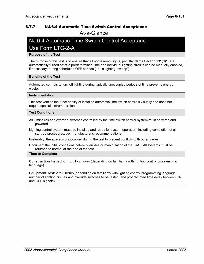
Acceptance Requirements Page 8-101
2005 Nonresidential Compliance Manual March 2005
8.7.7 NJ.6.4 Automatic Time Switch Control Acceptance
At-a-Glance NJ.6.4 Automatic Time Switch Control Acceptance Use Form LTG-2-A Purpose of the Test
The purpose of this test is to ensure that all non-exempt lights, per Standards Section 131(d)1, are automatically turned off at a predetermined time and individual lighting circuits can be manually enabled, if necessary, during scheduled OFF periods (i.e., a lighting “sweep”).
Benefits of the Test
Automated controls to turn off lighting during typically unoccupied periods of time prevents energy waste.
Instrumentation
This test verifies the functionality of installed automatic time switch controls visually and does not require special instrumentation.
Test Conditions
All luminaires and override switches controlled by the time switch control system must be wired and powered.
Lighting control system must be installed and ready for system operation, including completion of all start-up procedures, per manufacturer’s recommendations.
Preferably, the space is unoccupied during the test to prevent conflicts with other trades.
Document the initial conditions before overrides or manipulation of the BAS. All systems must be returned to normal at the end of the test.
Time to Complete
Construction Inspection: 0.5 to 2 hours (depending on familiarity with lighting control programming language)
Equipment Test: 2 to 6 hours (depending on familiarity with lighting control programming language, number of lighting circuits and override switches to be tested, and programmed time delay between ON and OFF signals)

Page 8-102-Acceptance Requirements
2005 Nonresidential Compliance Manual March 2005
Acceptance Criteria
Automatic time switch controls are programmed with acceptable weekday, weekend, and holiday schedules, per building occupancy profile.
The correct date and time are properly set in the lighting controller.
The battery back-up is installed and energized and is capable of retaining system programming for at least 10 hours if power is interrupted.
All lights can be turned ON manually or turn ON automatically during the occupied time schedule.
All lights turn OFF at the preprogrammed, scheduled times.
The manual override switch is functional and turns associated lights ON when activated.
Override time limit is no more than two hours, except for spaces exempt per §131(d)2.D.
Enunciator warning the occupants that the lights are about to turn OFF functions correctly. Potential Issues and Cautions
The manual override time limit can be adjusted to minimize test time, but the time limit setting must be reset upon completion of the test (not to exceed two hours).
It is preferable to perform the test when the spaces are unoccupied. Turning the lights OFF when other occupants are present can cause problems and unsafe working conditions.
Purpose (Intent) of the Test The purpose of this test is to ensure that all non-exempt lights per §131(a) are automatically turned off at a predetermined time and individual lighting circuits can be manually enabled, if necessary, during scheduled OFF periods. The most common term for this control strategy is a lighting “sweep”.
Construction Inspection • Automatic time switch control is programmed with acceptable
weekday, weekend, and holiday schedules. Non-exempt lights should be scheduled OFF a reasonable time after the space is typically unoccupied (i.e., 1 or 2 hours after most people have already left the space).
• Verify schedule and other programming parameter documentation was provided to the owner. This information will be used to verify system operation. The documentation should include weekday, weekend, and holiday schedules as well as sweep frequency and/or override time period. Sweep frequency or override time period refers to how often the OFF signal is sent through the system and commands the lights OFF again.
• Verify correct date and time is properly set in the time switch. Lights will not be controlled correctly if the programmed date and time do not match actual values.
• Verify the battery is installed and energized. Battery back-up should be capable of retaining system programming for at least 10 hours if power is interrupted.
• Override time limit is no more than 2 hours. When the lights are switched off, each lighting circuit can be turned back on manually.

Acceptance Requirements Page 8-103
2005 Nonresidential Compliance Manual March 2005
Most systems will either send out another OFF signal through the entire lighting network to command all lights back off, or consist of an override timer that will expire and turn off the lights that were manually turned on. Regardless of the control strategy, lights that were manually turned ON during an OFF period should only be operating for up to 2 hours before they are automatically turned off again.
• Verify that override switch is readily accessible and located so that a person using the device can see the lights being controlled--for example, individual override switch per enclosed office or centrally located switch when serving an open office space.
Equipment Testing
Step 1: Simulate occupied condition. Set ON time schedule to include actual time or adjust time to be within the ON time schedule (whichever is easier).
Verify and Document • All lights can be enabled. Some systems may turn the lights on
automatically at the scheduled time, but others may require that lights be turned on manually using their respective area control switch.
• Verify the local lighting circuit switch only operates lights in the area in which the switch is located. This is particularly important in enclosed spaces to ensure only lights within the enclosed space are controlled. However, switches serving open spaces should also control only lights in the designated zone.
Step 2: Simulate unoccupied condition. Set the OFF time schedule to include the actual time, or adjust the time to be within the OFF time schedule (whichever is easier).
Verify and Document • All non-exempt lights turn off. Most systems warn occupants that the
lights are about to turn off by sending a pulse through the lighting circuits to “flicker” the lights or provide another form of visual or audible annunciation.
• Manual override switch is functional. Enabling the manual override switch allows only the lights in the selected space where the switch is located to turn ON. This is particularly important in enclosed spaces to ensure only lights within the enclosed space are controlled, however, switches serving open spaces should also control only lights in the designated zone. The lights should remain ON throughout the override time period (refer to §131(d)2.D for maximum override times) and the system indicates that the lights are about to be turned off again.
• All non-exempt lights turn off when the next OFF signal is supplied to the lighting control circuits or the override time has expired. In order to reduce testing time associated with the complete OFF-Manual override-OFF sequence, it is recommended that the override time be

Page 8-104-Acceptance Requirements
2005 Nonresidential Compliance Manual March 2005
shortened so that the entire sequence can be witnessed within a reasonable amount of time.
Step 3: Return system back to normal operating condition. Ensure all schedules, setpoints, operating conditions, and control parameters are placed back at their initial conditions. Ensure the override time period is no more than two hours.
It is also good practice to leave a schedule in the timeclock itself for easy reference and to leave a blank schedule form so that the users can document any schedule changes. See the example below.
8.8 Mechanical Forms for Acceptance Requirements There are eight forms used to document the completion of these procedures. Each form includes a series of check boxes relating to each test or verification that needs to be performed. When completing the forms, check the appropriate box on the form after each test or verification is completed. Where the form includes data entry locations other than check boxes, enter the data requested on the form. These forms are located in Appendix A:
• Certificate of Acceptance (3 pages)
• Ventilation System Acceptance Document
• Packaged HVAC Systems Acceptance Document
• Air Distribution Acceptance Document
• Air-Side Economizer Acceptance Document
• Demand Control Ventilation Acceptance Document
• Supply Fan Variable Flow Control Acceptance Document
• Hydronic System Control Acceptance Document
MECH-1-A - Certificate of Acceptance Part 1 of 2 The form is separated into three basic sections: project information; general information; and statement of acceptance. Each section consists of a combination of data entry requirements and check boxes.
Project Information
• PROJECT NAME is the title of the project, as shown on the Code Compliance forms.
• DATE is the date of preparation of the compliance submittal package.
• PROJECT ADDRESS is the address of the project as shown on the Code Compliance forms.
• TESTING AUTHORITY is the person responsible for verifying all acceptance tests were performed and each system passed.

Acceptance Requirements Page 8-105
2005 Nonresidential Compliance Manual September 2005
• TELEPHONE is the phone number where the testing authority can be reached during regular business hours.
General Information
This section consists of a combination of data entry requirements and check boxes, all of which are self-explanatory. Complete check boxes and enter data as instructed.
Statement of Acceptance
This section consists of a combination of check boxes and data entry requirements, including signature; date; and license number. Complete check boxes and enter data as instructed.
MECH-1-A - Certificate of Acceptance Part 2 of 2 The form is used to document the overall final results of all acceptance test.
Summary of Acceptance Tests
• SYSTEM ACCEPTANCE DOCUMENT refers to the name of the test Form that has been completed. For example: “Ventilation System Acceptance document (AHU-1). This designates the acceptance test of outside air ventilation for air handling unit #1. Typically an individual form is completed for each piece of equipment tested.
• TESTING AUTHORITY is the person's name responsible for verifying all acceptance tests were performed and each system passed.
• DATE OF TEST is the date each test was actually performed.
• PASS/FAIL is the final outcome of the acceptance test.
MECH-2-A - Ventilation System Acceptance Document This form is used to document results of the minimum outside air ventilation tests for both constant and variable air volume fan systems. A separate form should be completed for each system tested. The form is separated into six basic sections: project information; pre-test inspection; equipment testing; testing calculations and results; pass/fail evaluation; and certification statement. Each section consists of a combination of data entry requirements and check boxes.

Page 8-106-Acceptance Requirements
2005 Nonresidential Compliance Manual March 2005
Project Information
• PROJECT NAME is the title of the project, as shown on the Code Compliance forms.
• DATE is the date of preparation of the compliance submittal package.
• PROJECT ADDRESS is the address of the project as shown on the Code Compliance forms.
• TESTING AUTHORITY is the person responsible for verifying all acceptance tests were performed and each system passed.
• TELEPHONE is the phone number where the testing authority can be reached during regular business hours.
• VENTILATION SYSTEM NAME/DESIGNATION is the name or unique identifier for the system being tested. For example: AHU-1; AC-3; etc.
Pre-test Inspection
This section consists of check boxes for both constant and variable air volume systems. Complete only the check boxes associated with the appropriate system type.
Equipment Testing
This section consists of data entry requirements for both constant and variable air volume systems. Enter data associated with the appropriate system type as instructed.
Testing Calculations and Results
This section consists of data entry requirements for both constant and variable air volume systems. Enter data associated with the appropriate system type as instructed.
Pass/Fail Evaluation
Check the appropriate box.
Certification Statement
The statement of compliance is signed by the person responsible for performing the test and verifying system performance. The signatory provides the following: name; company name; signature and date signed; as well as license number and expiration date.
MECH-3-A - Packaged HVAC System Acceptance Document This form is used to document results of packaged HVAC system operating tests. A separate form should be completed for each system tested. The form is separated into seven basic sections: project information; pre-test inspection;

Acceptance Requirements Page 8-107
2005 Nonresidential Compliance Manual March 2005
operating modes; equipment testing requirements; testing results; pass/fail evaluation; and certification statement. Each section consists of a combination of data entry requirements and check boxes.
Project Information
• PROJECT NAME is the title of the project, as shown on the Code Compliance forms.
• DATE is the date of preparation of the compliance submittal package.
• PROJECT ADDRESS is the address of the project as shown on the Code Compliance forms.
• TESTING AUTHORITY is the person responsible for verifying all acceptance tests were performed and each system passed.
• TELEPHONE is the phone number where the testing authority can be reached during regular business hours.
• PACKAGED HVAC NAME/DESIGNATION is the name or unique identifier for the system being tested. For example: ACU-1; DX-3; etc.
Pre-test Inspection
This section consists of check boxes. Complete check boxes as instructed.
Operating Modes
This section documents the various operating modes for packaged HVAC systems under which they will be tested. Note that operating modes “F” and “G” are associated with systems that do not have an economizer and operating modes “H” and “I” are associated with systems that do have an economizer. The operating modes associated with these two equipment types are mutually exclusive – either the unit has or doesn’t have an economizer.
Equipment Testing
This section consists of check boxes arranged in a matrix pattern, with the various operating modes listed horizontally and expected system responses listed vertically. As the HVAC system is tested under each applicable operating mode, check the box associated with the expected system response. Again, note that operating modes “F” and “G” are mutually exclusive with operating modes “H” and “I”. If the unit does not have an economizer, only modes “F” and “G” should be checked. Conversely, “H” and “I” are used only for systems with an economizer.
Testing. Results
This section consists of data entry requirements for all operating modes. Enter data associated with the appropriate operating mode as instructed.

Page 8-108-Acceptance Requirements
2005 Nonresidential Compliance Manual March 2005
Pass/Fail Evaluation
Check the appropriate box as instructed.
Certification Statement
The statement of compliance is signed by the person responsible for performing the test and verifying system performance. The signatory provides the following: name; company name; signature and date signed; as well as license number and expiration date.
MECH-4-A - Economizer Acceptance Document This form is used to document results of both stand-alone and DDC controlled economizer operating tests. A separate form should be completed for each system tested. The form is separated into six basic sections: project information; pre-test inspection; equipment testing requirements; testing results; pass/fail evaluation; and certification statement. Each section consists of a combination of data entry requirements and check boxes.
Project Information
• PROJECT NAME is the title of the project, as shown on the Code Compliance forms.
• DATE is the date of preparation of the compliance submittal package.
• PROJECT ADDRESS is the address of the project as shown on the Code Compliance forms.
• TESTING AUTHORITY is the person responsible for verifying all acceptance tests were performed and each system passed.
• TELEPHONE is the phone number where the testing authority can be reached during regular business hours.
• AIR ECONOMIZER NAME/DESIGNATION is the name or unique identifier for the economizer being tested (typically associated with a particular HVAC system). For example: AC-1; AHU-3; etc.
Pre-test Inspection
This section consists of check boxes for both stand-alone and DDC controlled economizers. Complete the appropriate check boxes as instructed.
Equipment Testing
• This section consists of check boxes for each test procedure. Complete check boxes as instructed.
Testing Results
• This section consists of data entry requirements for all tests. Enter data as instructed.

Acceptance Requirements Page 8-109
2005 Nonresidential Compliance Manual March 2005
Pass/Fail Evaluation
• Check the appropriate box as instructed.
Certification Statement
• The statement of compliance is signed by the person responsible for performing the test and verifying system performance. The signatory provides the following: name; company name; signature and date signed; as well as license number and expiration date.
MECH-5-A - Air Distribution Acceptance Document This form is used to document results of duct leakage tests performed on specific packaged HVAC systems. A separate form should be completed for each system tested. The form is separated into five basic sections: project information; pre-test inspection; equipment testing requirements; pass/fail evaluation; and certification statement. Each section consists of a combination of data entry requirements and check boxes.
Project Information
• PROJECT NAME is the title of the project, as shown on the Code Compliance forms.
• DATE is the date of preparation of the compliance submittal package.
• PROJECT ADDRESS is the address of the project as shown on the Code Compliance forms.
• TESTING AUTHORITY is the person responsible for verifying all acceptance tests were performed and each system passed.
• TELEPHONE is the phone number where the testing authority can be reached during regular business hours.
• AIR DISTRIBUTOR NAME/DESIGNATION is the name or unique identifier for the ductwork being tested (typically associated with a particular HVAC system). For example: ACU-1 ductwork; etc.
Construction Inspection
• This section consists of check boxes. Complete check boxes as instructed.
Certification Statement
• The statement of compliance is signed by the person responsible for performing the test and verifying system performance. The signatory provides the following: name; company name; signature and date signed; as well as license number and expiration date.
This form is used to verify duct tightness by the installer and/or HERS rater (third-party). Compliance credit requires third-party field verification.

Page 8-110-Acceptance Requirements
2005 Nonresidential Compliance Manual March 2005
Installer Certification
NEW CONSTRUCTION
• ENTER TEST LEAKAGE– enter the actual measured duct leakage value.
• FAN FLOW
CALCULATED FAN FLOW – enter the calculated fan flow either by multiplying 400cfm/ton times the number of tons of cooling or by entering 21.7 times the heating capacity of the unit being stalled in kBtu/h. In case of more than one separate fan flow unit calculate the fan flow for each separately and enter the value in the Measured Values column.
MEASURED FAN FLOW – enter the actual fan flow measured value in the Measured Values column.
• LEAKAGE PERCENTAGE – enter the leakage fraction by dividing the Test Leakage by either the calculated or measured fan flow. Enter the value in the Measured Values column.
PASS OR FAIL – check the “Pass” box if duct leakage is less than 6 %.
ALTERATIONS
• ENTER PRE-TEST LEAKAGE FLOW - enter the actual measured duct leakage value for existing ductwork where the single-zone unit is being replaced or having a major component replaced (§149E) including:
• Cooling coil
• Furnace
• Condenser coil (split system) or
• Condensing unit (split system)
Different levels of leakage requirements apply to new and existing ductwork (see §149D).
• ENTER FINAL TEST FOR LEAKAGE - enter the actual measured duct leakage value after alterations are complete. There are three options for meeting the leakage requirements.
• The measured duct leakage shall be less than 15% of fan flow; or
• The duct leakage shall be reduced by more than 60% relative to the leakage prior to the equipment having been replaced and a visual inspection shall demonstrate that all accessible leaks have been sealed; or
• If it is not possible to meet the duct sealing requirements of Subsections a. or b., all accessible

Acceptance Requirements Page 8-111
2005 Nonresidential Compliance Manual March 2005
leaks shall be sealed and verified through a visual inspection by a certified HERS rater.
EXCEPTION to Section 149(b)1Dii: Existing duct systems that are extended, which are constructed, insulated or sealed with asbestos.
Otherwise check the “Fail” box. See §149(b)1D for additional applicable information.
• ENTER REDUCTION IN LEAKAGE – This is option b. from above. If the leakage after the alteration is reduced by 60% then the system passes.
• NEW DUCTS – If all the ducts are new the leakage must not be over 6%. Enter this values here.
• TEST OR VERIFICATION STANDARDS • Leakage Percentage must be less than 15%. After
the alteration the duct leakage must be less than 15% of fan flow.
• Leakage Reduction - If a Pre-Test was conducted on the system before any alterations the final test after the alteration must less than 60%.
• If none of the above options a HERS rater can test the duct system to verify by smoke test that all accessible leaks have been sealed.
• SIGNATURE AND DATE – enter the signature of the installer and date of the test.
• NAME OF INSTALLING CONTRACTOR OR SUBCONTRACTOR – enter the name of the company of the contractor of subcontractor.
HERS Rater Compliance Statement The HERS rater fills out the following information:
• HERS RATER INFORMATION
• HERS Rater – Rater prints name and telephone number.
• CERTIFYING SIGNATURE – After tests passes the HERS Rater signs and dates form.
• FIRM – Enter company name
• SAMPLE GROUP NUMBER – Enter sample number here. Example, System 3 our of 7.
• ENTER TEST LEAKAGE– enter the actual measured duct leakage value.
• FAN FLOW
• CALCULATED FAN FLOW – enter the calculated fan flow either by multiplying 400cfm/ton times the number of tons of cooling or by entering 21.7 times the heating

Page 8-112-Acceptance Requirements
2005 Nonresidential Compliance Manual March 2005
capacity of the unit being stalled in kBtu/h. In case of more than one separate fan flow unit calculate the fan flow for each separately and enter the value in the Measured Values column.
• MEASURED FAN FLOW – enter the actual fan flow measured value in the Measured Values column.
• LEAKAGE PERCENTAGE – enter the leakage fraction by dividing the Test Leakage by either the calculated or measured fan flow. Enter the value in the Measured Values column.
• PASS OR FAIL – check the “Pass” box if duct leakage is less than 6 %.
ALTERATIONS
• ENTER PRE-TEST LEAKAGE FLOW - enter the actual measured duct leakage value for existing ductwork where the single-zone unit is being replaced or having a major component replaced (§149E) including:
• Cooling coil
• Furnace
• Condenser coil (split system) or
• Condensing unit (split system)
Different levels of leakage requirements apply to new and existing ductwork (see §149D).
• ENTER FINAL TEST FOR LEAKAGE - enter the actual measured duct leakage value after alterations are complete. There are three options for meeting the leakage requirements.
• The measured duct leakage shall be less than 15% of fan flow; or
• The duct leakage shall be reduced by more than 60% relative to the leakage prior to the equipment having been replaced and a visual inspection shall demonstrate that all accessible leaks have been sealed; or
• If it is not possible to meet the duct sealing requirements of Subsections a. or b., all accessible leaks shall be sealed and verified through a visual inspection by a certified HERS rater.
EXCEPTION to Section 149(b)1Dii: Existing duct systems that are extended, which are constructed, insulated or sealed with asbestos.
Otherwise check the “Fail” box. See §149(b)1D for additional applicable information.
• ENTER REDUCTION IN LEAKAGE – This is option b. from above. If the leakage after the alteration is reduced by 60% then the system passes.
• NEW DUCTS – If all the ducts are new the leakage must not be over 6%. Enter this value here.

Acceptance Requirements Page 8-113
2005 Nonresidential Compliance Manual March 2005
• TEST OR VERIFICATION STANDARDS • Leakage Percentage must be less than 15%. After
the alteration the duct leakage must be less than 15% of fan flow.
• Leakage Reduction - If a Pre-Test was conducted on the system before any alterations the final test after the alteration must less than 60%.
• If none of the above options a HERS rater can test the duct system to verify by smoke test that all accessible leaks have been sealed.
MECH-6-A - Demand Control Ventilation Acceptance Document This form is used to document results of operational tests for HVAC systems required to utilize demand ventilation control. A separate form should be completed for each system tested. The form is separated into six basic sections: project information; pre-test inspection; equipment testing requirements; testing results; pass/fail evaluation; and certification statement. Each section consists of a combination of data entry requirements and check boxes.
Project Information
• PROJECT NAME is the title of the project, as shown on the Code Compliance forms.
• DATE is the date of preparation of the compliance submittal package.
• PROJECT ADDRESS is the address of the project as shown on the Code Compliance forms.
• TESTING AUTHORITY is the person responsible for verifying all acceptance tests were performed and each system passed.
• TELEPHONE is the phone number where the testing authority can be reached during regular business hours.
• DEMAND CONTROL VENTILATION NAME/DESIGNATION is the name or unique identifier for the HVAC unit utilizing ventilation control that is being tested. For example: AC-1; AHU-3; etc.
Pre-test Inspection
• This section consists of check boxes. Complete check boxes as instructed.
Equipment Testing
• This section consists of both check boxes and data entry for each test procedure. Complete all check boxes and enter data as instructed.

Page 8-114-Acceptance Requirements
2005 Nonresidential Compliance Manual March 2005
Testing Results
• This section consists of data entry requirements for all tests. Enter data as instructed.
Pass/Fail Evaluation
• Check the appropriate box as instructed.
Certification Statement
The statement of compliance is signed by the person responsible for performing the test and verifying system performance. The signatory provides the following: name; company name; signature and date signed; as well as license number and expiration date.
MECH-7-A - Supply Fan Variable Flow Control Acceptance Document This form is used to document results of operational tests for HVAC supply fans required to utilize variable flow control. A separate form should be completed for each system tested. The form is separated into seven basic sections: project information; pre-test inspection; equipment testing requirements; test calculations; testing results; pass/fail evaluation; and certification statement. Each section consists of a combination of data entry requirements and check boxes.
Project Information
• PROJECT NAME is the title of the project, as shown on the Code Compliance forms.
• DATE is the date of preparation of the compliance submittal package.
• PROJECT ADDRESS is the address of the project as shown on the Code Compliance forms.
• TESTING AUTHORITY is the person responsible for verifying all acceptance tests were performed and each system passed.
• TELEPHONE is the phone number where the testing authority can be reached during regular business hours.
• VARIABLE FREQUENCY DRIVE NAME/DESIGNATION is the name or unique identifier for the supply fan that is being tested (typically associated with a particular HVAC system). For example: SF-1 in ACU-1; SF-2 in AHU-3 (multiple fan unit); etc.
Pre-test Inspection
• This section consists of check boxes. Complete check boxes as instructed.

Acceptance Requirements Page 8-115
2005 Nonresidential Compliance Manual March 2005
Equipment Testing
• This section consists of data entry requirements for each test procedure. Enter data as instructed.
Test Calculations
• This section consists of data entry requirements for all tests. Enter data as instructed.
Testing Results
• This section consists of data entry requirements for all tests. Enter data as instructed.
Pass/Fail Evaluation
• Check the appropriate box as instructed.
Certification Statement
• The statement of compliance is signed by the person responsible for performing the test and verifying system performance. The signatory provides the following: name; company name; signature and date signed; as well as license number and expiration date.
MECH-8-A - Hydronic System Acceptance Document This form is used to document the results for various hydronic system operating tests. The form was designed so that data from up to five hydronic systems (for example: chilled water; heating hot water; water-loop heat pump; etc.) could be recorded on one form. The form is separated into seven basic sections: project information; pre-test inspection; system type; select acceptance tests; equipment testing requirements; pass/fail evaluation; and certification statement. Each section consists of a combination of data entry requirements and check boxes.
Project Information
• PROJECT NAME is the title of the project, as shown on the Code Compliance forms.
• DATE is the date of preparation of the compliance submittal package.
• PROJECT ADDRESS is the address of the project as shown on the Code Compliance forms.
• TESTING AUTHORITY is the person responsible for verifying all acceptance tests were performed and each system passed.
• TELEPHONE is the phone number where the testing authority can be reached during regular business hours.

Page 8-116-Acceptance Requirements
2005 Nonresidential Compliance Manual March 2005
• HYDRONIC SYSTEM NAME/DESIGNATION is the name or unique identifier for the system(s) being tested. For example: Chilled water; heating hot water; water-loop heat pump; etc.
Pre-test Inspection
• This section consists of check boxes. Complete check boxes as instructed.
System Type
• This section documents the various system that will be tested. There are five columns under the “System ID” heading labeled 1 through 5 and are identified as follows: column 1 – chilled water systems; column 2 – heating hot water systems; column 3 – water-loop heat pumps; and column 4 and column 5 – other system types. Check each system type that is tested in the appropriate column.
Select Acceptance Test
• This section documents which of the various acceptance tests will be performed for each system type. Check the appropriate column for each test that applies to the respective system type.
Equipment Testing
• This section consists of check boxes and data entry requirements arranged by individual test. Check each box or enter data in each System ID column for which the specific test applies.
Pass/Fail Evaluation
• Check the appropriate box as instructed.
Certification Statement
• The statement of compliance is signed by the person responsible for performing the test and verifying system performance. The signatory provides the following: name; company name; signature and date signed; as well as license number and expiration date.
8.9 Lighting Forms for Acceptance Requirements There are three forms used to document the completion of these procedures. Each form includes a series of check boxes relating to each test or verification that needs to be performed. When completing the forms, check the appropriate box on the form after each test or verification is completed. Where the form includes data entry locations other than check boxes, enter the data requested on the form.
These forms are located in Appendix A.

Acceptance Requirements Page 8-117
2005 Nonresidential Compliance Manual September 2005
• Certificate of Acceptance (3 pages)
• Lighting Control Acceptance Document
• Automatic Daylighting Controls Acceptance Document
LTG-1-A - Certificate of Acceptance Part 1 of 2 The form is separated into three basic sections: project information; general information; and statement of acceptance. Each section consists of a combination of data entry requirements and check boxes.
Project Information
• PROJECT NAME is the title of the project, as shown on the Code Compliance forms.
• DATE is the date of preparation of the compliance submittal package.
• PROJECT ADDRESS is the address of the project as shown on the Code Compliance forms.
• TESTING AUTHORITY is the person responsible for verifying all acceptance tests were performed and each system passed.
• TELEPHONE is the phone number where the testing authority can be reached during regular business hours.
General Information
This section consists of a combination of data entry requirements and check boxes, all of which are self explanatory. Complete check boxes and enter data as instructed.
Statement of Acceptance
• This section consists of a combination of check boxes and data entry requirements, including signature; date; and license number. Complete check boxes and enter data as instructed.
LTG-1-A - Certificate of Acceptance Part 2 of 2 The form is used to document the overall final results of all acceptance test.
Summary of Acceptance Tests
• SYSTEM ACCEPTANCE DOCUMENT refers to the name of the test form that has been completed. For example: “Lighting ControlAcceptance document, LTG-2-A. This designates the acceptance test of outside air ventilation for air handling unit #1. Typically an individual form is completed for each piece of equipment tested.
• TESTING AUTHORITY is the person responsible for verifying all acceptance tests were performed and each system passed.

Page 8-118-Acceptance Requirements
2005 Nonresidential Compliance Manual September 2005
• DATE OF TEST is the date each test was actually performed.
• PASS/FAIL is the final outcome of the acceptance test.
LTG-2-A - Lighting Control Acceptance Document This form is used to document the results for various lighting control tests. The form was designed so that data for three lighting control strategies (occupancy sensors, manual daylight control, and automatic time switch) could be recorded on one form. The form is separated into six basic sections: project information; pre-test inspection; select acceptance tests; equipment testing requirements; pass/fail evaluation; and certification statement. Each section consists of a combination of data entry requirements and check boxes.
Project Information
• PROJECT NAME is the title of the project, as shown on the Code Compliance forms.
• DATE is the date of preparation of the compliance submittal package.
• PROJECT ADDRESS is the address of the project as shown on the Code Compliance forms.
• TESTING AUTHORITY is the person responsible for verifying all acceptance tests were performed and each system passed.
• TELEPHONE is the phone number where the testing authority can be reached during regular business hours.
• LIGHTING CONTROL SYSTEM NAME/DESIGNATION is the name or unique identifier for the system(s) being tested. For example: “occupancy sensors and lighting sweep”
Pre-test Inspection
• This section consists of check boxes. Complete check boxes as instructed.
Select Acceptance Test
• This section documents which of the acceptance tests were performed. Check the appropriate box for each applicable test.
Acceptance Requirements Page 8-119
2005 Nonresidential Compliance Manual March 2005
Equipment Testing
• This section consists of data entry requirements arranged by individual test procedures. There are three columns under the “Applicable Lighting Control System” heading labeled 1 through 3 and are identified as follows: column 1 – occupancy sensors; column 2 – manual daylighting controls; and column 3 – automatic time switch controls. Note that the columns are shaded when test procedures do not apply to a particular control strategy. Enter data as instructed in each column.
Pass/Fail Evaluation
• Check the appropriate box as instructed.
Certification Statement
• The statement of compliance is signed by the person responsible for performing the test and verifying system performance. The signatory provides the following: name; company name; signature and date signed; as well as license number and expiration date.
LTG-3-A - Automatic Daylighting Control Acceptance Document This form is used to document the results for automatic daylighting control tests. The form was designed so that data for three lighting control strategies (continuous dimming, stepped dimming, and stepped switching) could be recorded on one form. The form is separated into six basic sections: project information; pre-test inspection; control systems; equipment testing requirements; pass/fail evaluation; and certification statement. Each section consists of a combination of data entry requirements and check boxes.
Project Information
• PROJECT NAME is the title of the project, as shown on the Code Compliance forms.
• DATE is the date of preparation of the compliance submittal package.
• PROJECT ADDRESS is the address of the project as shown on the Code Compliance forms.
• TESTING AUTHORITY is the person responsible for verifying all acceptance tests were performed and each system passed.
• TELEPHONE is the phone number where the testing authority can be reached during regular business hours.
• AUTOMATIC DAYLIGHTING CONTROL NAME/DESIGNATION is the name or unique identifier for the system(s) being tested. For example: “continuous dimming – whole building”.

Page 8-120-Acceptance Requirements
2005 Nonresidential Compliance Manual March 2005
Pre-test Inspection
• This section consists of check boxes. Complete check boxes as instructed.
Control Systems
• This section documents which control strategy has been tested. Check the appropriate box for each applicable strategy.
Equipment Testing
This section consists of data entry requirements arranged by individual test procedures. There are three columns under the “Applicable Control System” heading labeled 1 through 3 and are identified as follows: column 1 – continuous dimming; column 2 – stepped dimming; and column 3 – stepped switching. Note that the columns are shaded when test procedures do not apply to a particular control strategy. Enter data as instructed in each column.
Pass/Fail Evaluation
• Check the appropriate box as instructed.
Certification Statement
• The statement of compliance is signed by the person responsible for performing the test and verifying system performance. The signatory provides the following: name; company name; signature and date signed; as well as license number and expiration date

INDEX Page 9-1
2005 Nonresidential Compliance Manual March 2005
9. INDEX
A
About the Standards, 1-28 Acceptable Metal to Metal Roof Constructions, 3-36 acceptance, 1-1, 1-2, 2-5, 2-6, 2-7, 4-2, 4-4, 4-9, 4-11, 4-12, 4-18, 4-30, 4-32, 4-33, 4-41, 4-43, 4-45, 4-53, 4-
59, 4-62, 4-65, 4-67, 4-79, 4-83, 4-84, 4-87, 4-114, 4-115, 4-116, 5-6, 5-81, 5-95, 8-1, 8-2, 8-3, 8-5, 8-6, 8-7, 8-8, 8-9, 8-10, 8-11, 8-12, 8-13, 8-14, 8-15, 8-16, 8-17, 8-19, 8-21, 8-25, 8-26, 8-29, 8-30, 8-35, 8-36, 8-50, 8-61, 8-65, 8-69, 8-76, 8-80, 8-85, 8-104, 8-105, 8-106, 8-107, 8-108, 8-109, 8-113, 8-114, 8-115, 8-116, 8-117, 8-118, 8-119
Acceptance Requirements, 1-6, 2-6, 4-32, 4-33, 4-43, 4-59, 4-62, 4-65, 4-67, 4-83, 4-85, 4-87, 4-89, 4-94, 4-114, 5-1, 5-81, 5-95, 8-1, 8-104
Acceptance Testing Process, 8-6 Acceptance Tests, 4-114, 8-3, 8-9, 8-105, 8-117 Accessibility, 5-11 ACM Manual, 1-2, 2-5, 2-7, 3-5, 3-6, 3-7, 3-9, 3-11, 3-13, 3-15, 3-22, 3-23, 3-27, 3-28, 3-30, 3-50, 3-71, 4-2,
4-32, 4-43, 4-67, 4-73, 4-75, 4-87, 4-88, 5-57, 5-59, 5-95, 5-107, 6-5, 6-32, 6-60, 6-62, 6-63, 6-64, 7-1, 7-8, 7-9, 7-10, 7-13, 7-14, 8-1, 8-8, 8-18, 8-49, 8-50
ACM Manual Appendix, 1-2, 2-5, 2-7, 3-5, 3-6, 3-7, 3-9, 3-11, 3-13, 3-15, 3-22, 3-23, 3-27, 3-28, 3-30, 3-50, 3-71, 4-32, 4-73, 4-75, 5-57, 5-59, 5-95, 6-5, 6-60, 6-62, 6-63, 6-64, 8-8, 8-50
Actual Lighting Power Calculation, 5-57 Addition Alone, 1-21 Addition Only, 7-11 Additions, 1-10, 1-11, 1-19, 1-21, 3-1, 3-64, 3-65, 4-1, 4-85, 4-86, 5-1, 5-80, 5-82, 5-83, 6-43, 6-55, 7-10, 7-
11 Additions – Prescriptive Requirements, 3-65 Adiabatic, 1-21 Adjustment of Ventilation Rate, 4-31 AFUE, 4-5, 4-41 Air and Water Measurements, 8-13 Air Cooled Chillers, 4-78 Air Delivery Systems, 4-93 Air-Side Economizer, 4-57, 4-58, 8-3, 8-8, 8-10, 8-13, 8-14, 8-18, 8-19, 8-34, 8-35, 8-36, 8-37, 8-38, 8-39, 8-
40, 8-56 allowed lighting, 1-8, 1-29, 5-3, 5-4, 5-35, 5-36, 5-37, 5-39, 5-40, 5-41, 5-43, 5-44, 5-45, 5-47, 5-48, 5-49, 5-
50, 5-53, 5-54, 5-55, 5-56, 5-57, 5-60, 5-63, 5-77, 5-78, 5-79, 5-80, 5-100, 5-105, 5-106, 6-18, 6-19, 6-20, 6-22, 6-23, 6-24, 6-25, 6-26, 6-28, 6-29, 6-32, 6-33, 6-35, 6-36, 6-38, 6-39, 6-40, 6-41, 6-48, 6-67, 7-8, 7-9, 7-10
Allowed Lighting Power, 5-3, 5-35, 5-79, 5-80, 5-99, 6-24 allowed power, 4-75, 5-35, 5-48, 5-49, 5-53, 5-54, 6-20, 6-23, 6-27, 6-28, 6-32, 6-36, 6-39, 6-40, 6-41, 6-64 ALLOWED SKYLIGHT, 3-73, 3-77 allowed U-factor, 3-55, 3-73 Alterations, 1-18, 1-19, 3-64, 3-65, 4-85, 4-87, 5-1, 5-82, 5-83, 6-43, 6-44, 6-45, 7-12 Alterations – Prescriptive Requirements, 3-65 Alterations of the Permitted Space, 7-12 altered existing duct systems, 8-52, 8-53, 8-54 Alternate Test Procedures for Hydronic System Controls Acceptance, 8-14

Page 9-2 INDEX
2005 Nonresidential Compliance Manual March 2005
Analysis Procedure, 7-5 annunciated, 5-11, 5-16 Apparatus, 8-51 Appliance Eff, 4-81, 4-85, 4-90, 4-91 Appliance Efficiency, 1-10, 1-20, 4-4, 4-5, 4-6, 4-91, 4-108, 5-11, 5-56, 5-82, 6-43, 6-44, 6-46 Appliance Standards, ix, 1-14, 1-15, 3-64, 4-79, 5-73 Application Scenarios, 7-8 Approaches, 1-7, 7-15 arcades, 5-16 Area category, 5-3 Area Category, 1-8, 5-3, 5-17, 5-35, 5-37, 5-41, 5-76, 5-77, 5-78, 5-89, 5-99, 5-100, 6-41 arenas, 5-16 ARI, 4-5, 4-6, 4-7, 4-8, 7-6, 7-7, 7-14, 8-52 ASHRAE, 3-23, 4-11, 4-12, 4-18, 4-20, 4-21, 4-29, 4-68, 4-69, 4-79, 4-100, 4-108, 5-20 Assembly, 1-11, 3-11, 4-13, 4-14, 8-58 assembly types, 3-55 Auction rooms, 8-58 auditorium, 4-11, 4-30, 4-42 Automatic Control Devices Certified, 5-92 automatic daylighting controls, 3-17, 5-3, 5-6, 5-7, 5-9, 5-18, 5-23, 5-26, 5-27, 5-68, 8-15, 8-16 Automatic Lighting Control Credits, 5-20, 5-63 automatic lighting controls, 3-18, 3-20, 5-3, 5-55, 5-63, 5-98 Automatic shut-off controls, 1-14, 1-16, 8-16 Automatic Shutoff Controls, 6-10 Automatic time, 4-53, 4-67, 5-7, 5-14, 5-81, 6-10, 8-102
B
Ballast, 5-92 ballasts, 1-19, 1-20, 1-28, 5-11, 5-60, 5-65, 5-66, 5-70, 5-74, 5-75, 5-82, 5-95, 5-102, 5-103, 5-104, 5-105, 6-
4, 6-6, 6-43, 6-44, 6-45, 6-46, 6-48, 6-50, 6-51, 6-52, 6-53, 6-60, 6-61, 6-62, 6-63, 6-64, 6-69, 6-70, 8-86, 8-90, 8-91, 8-99
Bank/Financial Institution, 4-15 bars, 4-100 Basic Data Entry, 7-6 Beverly County, 6-17 boilers, 4-5, 4-7, 4-50, 4-53, 4-66, 4-67, 4-90, 4-107, 8-5, 8-10, 8-67, 8-68, 8-70, 8-72, 8-77, 8-78, 8-79, 8-81 Bryan Avenue, 6-16 building, 1-1, 1-2, 1-4, 1-5, 1-6, 1-7, 1-8, 1-9, 1-11, 1-12, 1-13, 1-15, 1-16, 1-18, 1-19, 1-20, 1-21, 1-22, 1-23,
1-24, 1-25, 1-26, 1-27, 1-28, 1-29, 1-30, 1-31, 1-32, 2-1, 2-2, 2-3, 2-4, 2-5, 2-7, 2-8, 2-9, 2-10, 2-11, 2-12, 2-13, 3-1, 3-2, 3-3, 3-4, 3-5, 3-6, 3-7, 3-9, 3-10, 3-11, 3-12, 3-14, 3-15, 3-17, 3-18, 3-20, 3-23, 3-25, 3-27, 3-28, 3-29, 3-30, 3-31, 3-33, 3-34, 3-35, 3-37, 3-38, 3-39, 3-42, 3-43, 3-45, 3-48, 3-49, 3-50, 3-51, 3-52, 3-53, 3-54, 3-55, 3-56, 3-57, 3-58, 3-59, 3-60, 3-61, 3-62, 3-63, 3-64, 3-65, 3-66, 3-67, 3-68, 3-69, 3-70, 3-71, 3-72, 3-73, 3-74, 3-75, 3-76, 3-77, 3-78, 3-79, 3-80, 3-81, 3-83, 3-84, 4-2, 4-3, 4-4, 4-5, 4-9, 4-11, 4-16, 4-17, 4-21, 4-22, 4-25, 4-27, 4-28, 4-29, 4-31, 4-33, 4-34, 4-36, 4-46, 4-47, 4-48, 4-50, 4-51, 4-57, 4-58, 4-59, 4-63, 4-64, 4-66, 4-67, 4-68, 4-69, 4-70, 4-71, 4-74, 4-76, 4-77, 4-78, 4-80, 4-83, 4-84, 4-85, 4-87, 4-88, 4-89, 4-91, 4-92, 4-94, 4-99, 4-100, 4-101, 4-102, 4-103, 4-108, 4-109, 4-113, 4-114, 4-115, 5-1, 5-2, 5-3, 5-4, 5-6, 5-7, 5-11, 5-12, 5-14, 5-17, 5-18, 5-31, 5-35, 5-36, 5-37, 5-38, 5-40, 5-43, 5-44, 5-50, 5-54, 5-55, 5-57, 5-58, 5-59, 5-61, 5-63, 5-66, 5-67, 5-68, 5-70, 5-72, 5-73, 5-74, 5-75, 5-76, 5-77, 5-78, 5-79, 5-81, 5-82, 5-84, 5-87, 5-88, 5-89, 5-90, 5-91, 5-92, 5-93, 5-94, 5-95, 5-96, 5-97, 5-99, 5-100, 5-101, 5-105, 5-106, 6-1, 6-2, 6-3, 6-4, 6-5, 6-8, 6-9, 6-10, 6-11, 6-15, 6-19, 6-25, 6-26, 6-27, 6-29, 6-30, 6-31, 6-32, 6-33, 6-37, 6-39, 6-41, 6-53, 6-54, 6-55, 6-56, 6-57, 6-58, 6-59, 6-65, 6-66, 6-68, 6-70, 7-1, 7-2, 7-3, 7-4, 7-5, 7-6, 7-7, 7-8, 7-9, 7-10, 7-11, 7-12, 7-13, 7-16, 7-17, 8-1, 8-2, 8-3, 8-5, 8-6, 8-9, 8-12, 8-13, 8-15, 8-17, 8-20, 8-22, 8-23, 8-24, 8-26, 8-35, 8-36, 8-
INDEX Page 9-3
2005 Nonresidential Compliance Manual March 2005
37, 8-39, 8-53, 8-63, 8-64, 8-66, 8-67, 8-68, 8-71, 8-72, 8-73, 8-79, 8-80, 8-83, 8-84, 8-96, 8-102, 8-119
Building automation system, 8-56 building code, 5-6 building component, 7-13 building components, 7-13 Building Department Field Inspection, 2-5 Building departments, 2-7, 4-116, 5-84, 7-3, 8-2, 8-8 building envelope, 2-12 Building Envelope, 1-8, 1-29, 3-1, 3-65, 3-66, 5-80 Building Facades, 6-29, 6-42 Building Lighting, 5-78, 5-92 Building Permit, 2-1, 2-3, 2-4 Building Types Covered, 1-9, 3-64, 4-79, 5-73 Business and Professions Code, 2-9, 3-69, 4-103, 5-95, 6-55
C
CalCerts, 8-46 Calculating TDV Energy, 7-7 Calculating the Lighting Power, 5-55 California Climate Zones, 1-30, 1-31 California Code of Regulations, 2-10, 6-56 California Energy Commission, 1, 2, 3, 1-1, 1-28, 3-10, 3-11, 4-2, 4-83, 5-2, 5-92, 6-5, 6-16, 8-13, 8-14, 8-35,
8-37, 8-46 California Quality Standards, 3-32, 3-33, 3-69 California Safety Code, 4-32 canopy lighting, 6-36, 6-37, 6-45, 6-46 captive-key override, 5-16 category E, 5-53 category G, 5-103, 5-105 CEC Alternate Default U-Factor and SHGC Label Certificate Air Leakage, 3-11 CEC Approval, 7-2 CEC DEFAULT, 3-10, 5-95 CEC Default U-Factor and SHGC Label Certificate, 3-10 ceilings, 1-6, 1-16, 1-27, 3-2, 3-28, 3-33, 3-34, 3-35, 3-50, 4-87, 4-88, 5-87, 7-2, 7-6 central plant, 4-51, 4-66, 4-74, 4-77 Centrifugal Fan Limitation, 4-78 Certificate of Compliance, 2-6, 2-8, 2-9, 2-13, 3-67, 4-101, 4-113, 5-89, 5-95, 5-108, 6-54, 6-55, 6-70, 7-10,
7-14, 7-15, 7-16, 8-7 Certificate of Occupancy, 2-1, 2-5, 2-7, 4-116, 8-2, 8-7, 8-8 Certification, 3-5, 3-32, 4-3, 4-5, 4-53, 5-6, 5-83, 6-5, 8-13, 8-14, 8-50, 8-55, 8-106, 8-108, 8-109, 8-114, 8-
115, 8-116, 8-119, 8-120 Certified Insulation Material, 3-32 CFA, 1-23 chandeliers, 5-4, 5-17, 5-38, 5-43, 5-49, 5-57, 5-103, 6-33, 6-38, 6-39 change of occupancy, 1-22 Changeover, 4-30, 4-31 changeover systems, 4-30, 4-31 Changes of Occupancy, 1-22 CHEERS, 8-46 churches, 1-11, 3-17, 4-50, 5-15 Classes of Wall Constructions., 3-39 Climate Zones, 1-30
Page 9-4 INDEX
2005 Nonresidential Compliance Manual March 2005
CO2, 1-6, 4-27, 4-28, 4-29, 4-30, 4-33, 4-53, 4-100, 4-105, 8-13, 8-56, 8-57, 8-58, 8-59, 8-60 combustion efficiency, 4-5, 4-7, 4-90 commercial, 4-2, 4-22, 4-40, 5-1, 5-2, 5-36, 5-42, 5-43, 5-66, 5-86, 6-14, 6-15, 6-38, 8-28 Common Lighting Systems, 2-9, 5-73, 5-75, 5-89, 5-106 complete building, 1-24, 5-2, 5-36, 5-37, 5-55, 5-58, 5-59, 7-8, 7-9 Complete Building Method, 1-8, 5-35, 5-36, 5-76, 5-78, 5-79, 5-99, 5-106 Compliance and Enforcement, 2-1, 2-2 Compliance Approaches, 1-28, 4-3, 4-86 Compliance By Permit Stage, 7-14 Compliance Documentation, 2-8, 3-67 Compliance Forms, 2-8, 2-9, 7-15 Component Performance Method, 6-48 Conditioned Space, 1-17, 1-23, 1-24 Constructability Plan Review, 8-16 Construction Documents, 2-8 Construction Inspection, 2-6, 8-7, 8-16, 8-21, 8-22, 8-26, 8-30, 8-36, 8-38, 8-47, 8-48, 8-50, 8-58, 8-63, 8-66,
8-67, 8-70, 8-74, 8-78, 8-79, 8-82, 8-87, 8-94, 8-95, 8-98, 8-99, 8-101, 8-102, 8-109 Construction Phase, 2-4 control valves, 4-65, 4-66, 4-67, 4-107, 8-10, 8-11, 8-14, 8-65, 8-66, 8-67, 8-68, 8-69, 8-77, 8-78, 8-79, 8-80,
8-81, 8-83, 8-84 Cooling Tower Flow Turndown, 4-77 COP, 4-5, 4-7, 4-8, 4-41 cost-effectiveness, 1-12 Cut-Off Luminaires, 6-7 Cycling fans, 8-6
D
Daylit Area Control, 5-92 Daylit Area under Skylights, 3-19 DCV controls, 4-28, 8-4, 8-57 DDC Controls, 8-43 Deadhead, 8-68, 8-70, 8-79 Defeat the economizer, 8-59 Definitions of Efficiency, 4-90 Definitions of Spaces and Systems, 4-91 demand control ventilation, 4-33, 4-105, 8-22, 8-27, 8-28, 8-56, 8-57, 8-58 Demand Controlled Ventilation, 4-27, 4-33, 4-100 Design Phase, 2-2 Determining Fenestration U-factors, 3-22, 3-31 Determining Luminaire Wattage, 5-59, 5-61, 6-5 diagnostic, 1-2, 4-88, 8-40, 8-50, 8-51 Diagnostic Duct Leakage, 8-52 diagnostic tests, 8-51 Direct Air Transfer, 4-17 Directly Conditioned Space, 1-23 Distribution of Outdoor Air to Zonal Units, 4-17 Drive-up Windows, 6-39, 6-40, 6-68 Duct Efficiency, 1-6 Duct Leakage Measurements, 8-51 Duct Pressurization, 8-51 duct work, 1-20, 1-21, 4-7, 4-17, 4-36, 4-39, 4-70, 8-36, 8-37, 8-46, 8-48, 8-56

INDEX Page 9-5
2005 Nonresidential Compliance Manual March 2005
E
ECM Motors for Series Style VAV Boxes, 4-76 Economizers, 4-3, 4-56, 4-58, 4-84, 4-86, 4-89, 4-94, 4-114, 4-115, 8-5, 8-9, 8-37 EER, 4-5, 4-7, 4-41, 4-42, 4-61, 4-88 Elaine Lane, 6-17 Electricity Reliability and Demand, 1-3 Elizabeth Street, 6-16 Enclosed Space, 1-24 Energy Commission, 1-1, 1-3, 1-5, 1-28, 1-30, 2-1, 2-4, 2-5, 2-7, 3-32, 3-62, 3-67, 3-70, 3-71, 4-4, 4-5, 4-6, 4-
11, 4-18, 4-53, 4-81, 4-101, 5-3, 5-6, 5-7, 5-8, 5-11, 5-21, 5-55, 5-89, 5-92, 5-107, 6-2, 6-3, 6-5, 6-6, 6-11, 6-13, 6-14, 6-15, 6-16, 6-54, 6-58, 6-59, 6-60, 6-62, 6-63, 6-64, 7-1
Enforcement and Compliance, 7-13 Entire Building, 1-24 Entire Existing Buildings Plus Alteration, 7-12 Envelope Insulation, 3-31, 3-65, 3-67 Equipment Requirements, 4-4 Equipment Testing, 8-22, 8-27, 8-31, 8-49, 8-59, 8-63, 8-66, 8-68 Eurlyne Park,, 6-16 Exception to Equipment Testing, 8-24 Exempt Lighting, 5-56 Existing Construction by Permit Stage, 7-10 Existing Plus Addition, 7-11 Existing-Plus-Addition, 1-21 Exit Way and Egress Lighting, 5-72
F
façade lighting, 6-10, 6-26, 6-29, 6-31, 6-32, 6-33, 6-46 Fan Power Consumption, 4-70, 4-111 Fan Power Index, 4-90 Fan Pressurization of Ducts, 8-52, 8-53 Fenestration and Doors, 3-49 Fenestration Heat Transfer, 3-63 Field Inspector Responsibilities, 2-13 Field Process, 8-9, 8-16 field verification, 1-2, 1-6, 4-88, 6-70, 8-8, 8-12, 8-109 final test, 8-49, 8-50, 8-111, 8-113 flowmeter, 8-46, 8-49, 8-53 Forms, Plan Check, Inspection and Acceptance Tests, 5-6 Four Surface Orientations, 3-13 four-story building, 1-27 frontage, 6-3, 6-4, 6-16, 6-29, 6-33, 6-34, 6-35, 6-66, 6-67, 6-71 Furnace Standby Loss Controls, 4-6 Future Construction by Permit Stage, 7-9
G
Gary Ave, 6-16 General Procedure, 7-5 General Site Illumination, 6-3, 6-18, 6-21, 6-59 Glossary/Reference, 4-89 Graph of Overhang Factors, 3-26

Page 9-6 INDEX
2005 Nonresidential Compliance Manual September 2005
gross wall area, 3-12, 3-53, 3-60, 6-32 Guarded Facilities, 6-40, 6-42, 6-68
H
Habitable Story, 1-24 Heat Rejection Fan Control, 4-64 HERS, 2-1, 2-7, 4-40, 4-41, 4-87, 4-88, 8-46, 8-47, 8-49, 8-50, 8-52, 8-53, 8-54, 8-109, 8-111, 8-112, 8-113 HERS rater, 8-47, 8-50 High Efficacy Luminaires, 5-1, 5-81 High-rise residential, 1-14 High-rise Residential, 1-13, 4-83 Historic Buildings, 1-5, 1-10, 3-64, 4-79, 5-1, 5-73 History, 1-28, 6-2 Hospitals, 6-27 Hotel/Motel, 1-13, 1-25, 4-45, 5-16, 5-17 Hotels and Motels, 1-15 HVAC Energy Use, 4-2 HVAC system, 1-20, 1-21, 1-22, 1-25, 1-26, 3-5, 3-62, 3-64, 4-19, 4-32, 4-67, 4-94, 5-86, 8-27, 8-28, 8-29, 8-
30, 8-35, 8-36, 8-47, 8-56, 8-58, 8-59, 8-60, 8-96, 8-106, 8-107, 8-108, 8-109, 8-114 HVAC System Requirements, 4-67 HVAC systems and water heating systems, 1-1
I
Illuminated Area, 2-9, 6-19, 6-64, 6-65, 6-66, 6-67, 6-68 Individual Room/Area Controls, 5-92 Indoor Lighting, 1-6, 1-8, 1-25, 2-6, 5-1, 5-83 inefficient lighting systems, 6-58 Infiltration and Air Leakage, 3-49 installed lighting power, 3-21, 5-3, 5-27, 5-48, 5-58, 5-59, 5-68, 5-93, 5-107, 5-108, 6-2, 6-58 Installer Certification, 8-110 Instrumentation Specifications, 8-50 Insulation
Prescriptive Compliance, 1-7 Indoor Lighting, 1-29, 2-9, 5-89, 5-93, 5-94 Intermittently Occupied Spaces, 4-100 Interzone Surfaces, 3-63 IPLV, 4-5, 4-7, 4-8
J
Jon Road, 6-17
L
Labeling requirements for tested systems, 8-55 leakage percentage, 8-49, 8-50, 8-53 Lighting Acceptance Test Issues, 8-17 Lighting Acceptance Testing Overview, 8-15 Lighting Applications, 6-3, 6-20, 6-46 Lighting Design Procedures, 5-6

INDEX Page 9-7
2005 Nonresidential Compliance Manual September 2005
lighting fixtures, 1-19, 1-20, 3-49, 5-39, 5-45, 5-55, 5-58, 5-61, 5-84, 5-85, 5-86, 5-95, 5-96, 6-43, 6-45, 6-46, 7-16
Lighting Forms for Acceptance Requirements, 8-116 Lighting Inspection, 6-70 Lighting Mandatory Measures, 6-57 Lighting Plan Check Documents, 5-1, 5-88, 6-53 Lighting Power, 1-7, 3-19, 5-35, 5-36, 5-40, 5-41, 5-47, 5-48, 5-51, 5-52, 5-57, 5-70, 5-76, 5-89, 5-95, 5-96,
5-99, 5-100, 5-102, 5-103, 5-104, 5-106, 6-3, 6-18, 6-43, 6-44, 6-45, 6-62, 6-63 Lighting Test Procedures, 8-5 Lighting Trade-offs, 5-3 Lighting Under Canopies, 6-37 Lighting Vehicle Service Stations, 6-35 Lighting Zone Adjustments by Local Jurisdictions, 6-14 Lighting Zones, 6-4, 6-12, 6-13, 6-14, 6-16, 6-18, 6-25, 6-46, 6-51 Live-Work Spaces, 1-16 Living quarters, 1-13, 1-14, 5-56 Local Ordinances, 6-24 Low airflow, 8-6 Low-rise Residential Buildings, 1-10 Low-Rise Residential Standards, 3-68, 4-102, 5-90 LTG-1-C, 2-9, 5-89, 5-90, 5-91, 5-93, 5-94, 5-95, 5-97, 5-98, 5-102, 5-103, 5-104, 5-108, 6-28, 6-53, 6-69, 7-
14, 7-15, 7-16, 8-7 LTG-1-C Part 1 of, 5-90 LTG-1-C Part 2 of 4, 5-93 LTG-1-C Part 3 of 4, 5-94 LTG-1-C Part 4 of 4, 5-95 LTG-2-C: Indoor Lighting Schedule, 5-95 LTG-3-C: Portable Lighting Worksheet, 5-96 LTG-4-C: Lighting Controls Credit Worksheet, 5-98 LTG-5-C5: Indoor Lighting Power Allowance, 5-99 LTG-6-C: Tailored Method, 5-100 LTG-7-C: Room Cavity Ratio Worksheet (>3.5), 5-105 LTG-8-C: Common Lighting Systems, 5-106 LTG-9-C: Line Voltage Track Lighting, 5-107
M
Mandatory Measures, 1-7, 1-8, 1-14, 1-15, 3-5, 3-32, 3-42, 3-64, 3-65, 3-69, 4-3, 4-33, 4-43, 4-85, 5-6, 5-82, 5-91, 6-3, 6-5
manufacturing facility, 1-26 marquee, 6-31, 6-33, 6-38, 6-39 Mazi Memorial Expressway, 6-16 MECH-2-C (Part 1 of 3) Air System Requirements, 4-104 MECH-2-C (Part 2 of 3) Water Side System Requirements, 4-107 MECH-2-C (Part 3 of 3) Service Hot Water & Pool Requirements, 4-108 MECH-2-C Overview, 4-103 Mechanical, 1-8, 1-17, 1-19, 1-25, 1-29, 2-7, 2-9, 3-1, 4-1, 4-2, 4-4, 4-5, 4-10, 4-13, 4-15, 4-36, 4-39, 4-63, 4-
85, 4-86, 4-100, 4-101, 4-103, 4-109, 4-113, 4-114, 4-115, 5-77, 5-78, 7-14, 7-15, 7-16, 8-1, 8-2, 8-8, 8-9, 8-14, 8-17, 8-20, 8-23, 8-24, 8-26, 8-27, 8-45, 8-104
Mechanical Acceptance Test Issues, 8-10 Mechanical Cooling, 1-25 Mechanical Heating, 1-25 Mechanical Test Procedures, 8-3 Minimum Capabilities, 7-2

Page 9-8 INDEX
2005 Nonresidential Compliance Manual March 2005
Minimum Lamp Efficacy, 5-82, 6-6 Minimum Skylight For Large Enclosed Spaces, 5-80 Miscellaneous Dampers, 4-31 Mixed Occupancies, 1-26 Mixed Use Buildings, 1-13 Multi-Level Switching, 5-13, 5-14, 5-31, 6-11
N
Nelson River, 6-17 New Construction in Existing Buildings, 1-18 Newly Conditioned Space, 1-18 NJ.10.1 Variable Hydronic Flow Controls Acceptance, 8-65 NJ.10.2 Automatic Isolation Controls Acceptance, 8-11, 8-65, 8-69, 8-70 NJ.10.3 Supply Water Temperature Reset Controls Acceptance, 8-71, 8-73 NJ.10.4 Water-loop Heat Pump Controls Acceptance, 8-11, 8-76, 8-77, 8-79 NJ.10.5 Pump Variable Frequency Drive Controls Acceptance, 8-80 NJ.3.1 Variable Air Volume Systems Outdoor Air Acceptance, 8-10, 8-17, 8-19, 8-61, 8-62 NJ.3.2 Constant Volume Systems Outdoor Air Acceptance, 8-10, 8-17, 8-25, 8-26 NJ.4.1 Constant Volume Packaged HVAC Systems Acceptance, 8-10, 8-17, 8-25, 8-28, 8-30 NJ.5.1 Air Distribution Acceptance, 8-18, 8-46, 8-48 NJ.6.1 Automatic Daylighting Control Acceptance, 8-86, 8-87 NJ.6.2 Occupancy Sensor Acceptance, 8-94, 8-95 NJ.6.3 Manual Daylighting Control Acceptance, 8-97 NJ.6.3 Manual Daylighting Control Acceptance, 8-98 NJ.6.4 Automatic Time Switch Control Acceptance, 8-101 NJ.7.1 Air-Side Economizer Acceptance, 8-10, 8-18, 8-34, 8-35, 8-37, 8-40 NJ.8.1 Demand Control Ventilation Acceptance, 8-10, 8-19, 8-25, 8-26, 8-28, 8-56, 8-57 NJ.9.1 Supply Fan Variable Flow Controls Acceptance, 8-10, 8-19, 8-23, 8-61, 8-63 NJ10.1 Variable Flow Controls, 8-18 NJ10.2 Automatic Isolation Controls, 8-18 NJ10.3 Supply Water Temperature Reset Controls, 8-18 NJ10.4 Water-loop Heat Pump Controls, 8-18 NJ10.5 Variable Frequency Drive Control, 8-18 NJ8.1 Packaged Systems DCV Acceptance, 8-18 No Flow Measurement, 8-67 No outdoor air, 8-6 Nonresidential Buildings, 2, 3-6, 3-7, 3-10, 3-11 Nonresidential Climate Regions, 3-3 Nonresidential Occupancies, 1-13 normal operating condition, 8-11, 8-17, 8-24, 8-28, 8-35, 8-42, 8-43, 8-45, 8-60, 8-64, 8-67, 8-68, 8-71, 8-
75, 8-78, 8-79, 8-83, 8-85, 8-93, 8-97, 8-100, 8-104
O
Occupancy, 1-11, 1-12, 1-13, 1-25, 1-26, 2-6, 2-7, 2-8, 4-14, 4-25, 4-26, 4-27, 4-84, 5-64, 5-65, 5-71, 5-81, 8-2, 8-5, 8-16, 8-50, 8-58, 8-85, 8-94, 8-95, 8-96
Occupancy Permit, 2-7 office, 3, 1-11, 1-12, 1-13, 1-15, 1-18, 1-24, 3-7, 3-20, 3-29, 3-30, 3-39, 4-16, 4-17, 4-42, 4-43, 4-48, 4-55, 4-
56, 4-100, 5-4, 5-12, 5-28, 5-38, 5-52, 5-53, 5-57, 5-58, 5-59, 5-64, 5-65, 5-79, 5-85, 5-87, 5-96, 5-97, 6-37, 6-38, 7-12, 8-95, 8-96, 8-103
OLTG-1-C, 2-9, 5-91, 5-108, 6-28, 6-53, 6-54, 6-59, 6-60, 6-61, 6-62, 6-63, 6-69, 6-70 OLTG-2-C, 2-9, 6-28, 6-54, 6-59, 6-61, 6-62, 6-63, 6-64, 6-65, 6-66, 6-67, 6-68 OLTG-2-C: LIGHTING COMPLIANCE SUMMARY, 6-54

INDEX Page 9-9
2005 Nonresidential Compliance Manual March 2005
OLTG-3-C, 2-9, 6-59, 6-60, 6-61, 6-62, 6-64, 6-65, 6-66, 6-67, 6-68 OLTG-3-C: AREA CALCULATION WORKSHEETS, 6-54 OLTG-4-C: SIGN LIGHTING COMPLIANCE, 6-54 Opaque Surface Heat Transfer, 3-63 Opaque Surface Mass Characteristics, 3-62 Organization and Content, 1-1 orientation, 1-7, 2-2, 3-4, 3-5, 3-10, 3-11, 3-13, 3-26, 3-50, 3-53, 3-56, 3-57, 3-58, 3-59, 3-63, 3-74, 3-75, 3-
81, 3-82, 3-83, 4-31, 4-46, 6-67, 7-6 Ornamental Lighting, 6-38, 6-39, 6-42 Other Occupancy, 1-26 Outdoor Dining, 6-41, 6-42 outdoor lighting, 1-1, 1-7, 1-11, 1-14, 1-15, 1-19, 1-28, 1-29, 2-1, 5-1, 5-3, 5-10, 5-38, 5-67, 6-1, 6-2, 6-3, 6-4,
6-5, 6-6, 6-7, 6-8, 6-10, 6-11, 6-12, 6-18, 6-19, 6-24, 6-28, 6-31, 6-37, 6-42, 6-43, 6-44, 6-45, 6-46, 6-51, 6-53, 6-54, 6-55, 6-58, 6-59, 6-69, 6-70, 7-7
Outdoor lighting, 1-13, 1-14, 1-15, 6-1, 6-71 Outdoor Lighting, 1-7, 1-8, 1-29, 2-9, 5-17, 5-73, 5-89, 5-108, 6-1, 6-2, 6-3, 6-4, 6-15, 6-18, 6-24, 6-43, 6-44,
6-45, 6-55 Outdoor luminaire cutoff, 6-58 Outdoor Sales Frontage, 6-34 Overall Envelope Approach, 1-8, 3-3, 3-51, 3-65, 3-67 Overall Heat Gain, 3-56, 3-78, 3-80, 3-81, 3-83 Overall Heat Loss, 3-51, 3-77, 3-83 Overhang Dimensions, 3-25 Overhangs, 3-63 Overview, 2-1, 3-1, 3-64, 3-65, 3-66, 4-1, 4-79, 5-2, 5-73, 5-83, 6-1, 6-12, 8-1, 8-8
P
parking garage, 5-38, 6-28 performance approach, 1-1, 1-7, 1-8, 1-9, 1-12, 1-19, 1-21, 1-22, 1-29, 1-30, 2-4, 2-12, 3-1, 3-2, 3-3, 3-4, 3-
34, 3-46, 3-62, 3-64, 3-71, 4-3, 4-4, 4-83, 4-88, 4-95, 5-2, 5-3, 5-6, 5-54, 5-55, 5-68, 5-82, 5-84, 6-50, 7-1, 7-7, 7-8, 7-9, 7-10, 7-11, 7-12, 7-14
Performance Approach, 1-7, 1-8, 1-30, 3-1, 3-4, 3-62, 4-1, 4-4, 4-83, 4-84, 4-86, 4-89, 5-1, 5-54, 6-46, 6-52, 7-1
Performance Compliance, 1-14, 1-16, 7-10, 7-12, 7-13 Performance Concepts, 7-1 Performance Inspection, 7-16 Permit Application, 2-3 Pilot Lights, 4-4, 4-6, 4-85 Plan Check, 2-4, 4-2, 4-100, 5-1, 5-6, 5-88, 5-108, 6-53, 8-20, 8-23, 8-24, 8-26, 8-27 Plan Review, 2-6, 4-115 Plans Examiner Responsibilities, 2-13 Pool and Spa Heating Systems, 4-4, 4-81, 4-85 Portable Lighting Systems, 5-57 Power Allowances, 1-8, 5-51, 6-18, 6-24 prescriptive approach, 1-7, 1-8, 1-9, 1-29, 1-30, 1-31, 2-4, 3-45, 3-51, 4-76, 4-111, 5-3, 5-35, 5-54, 6-47, 6-48,
6-50, 6-51, 7-1, 7-16 Prescriptive Approach, 1-8, 1-29, 3-58, 4-59, 4-111, 5-35, 5-83, 6-47, 6-48, 6-50 Prescriptive Compliance, 1-14, 1-16 prescriptive lighting requirements, 1-8 prescriptive mechanical requirements, 1-8, 1-29 Prescriptive Packages, 1-8 Prescriptive Requirements, 2-9, 3-2, 3-12, 3-14, 3-34, 3-45, 3-65, 3-66, 4-3, 4-40, 4-54, 4-86, 4-87, 4-101, 4-
111, 5-83

Page 9-10 INDEX
2005 Nonresidential Compliance Manual March 2005
Present Value Savings of Skylight, 3-17 Pressure Measurements, 8-51 Pre-test, 8-49, 8-107, 8-113, 8-114, 8-116, 8-118, 8-119 Professional Judgment, 7-3 Relocatble Public School Buildings, 1-6, 3-35, 3-37, 3-40, 3-50, 3-68
R
raised floor, 1-8 Randel River, 6-16 Readily accessible area, 1-14, 1-15 recreation areas, 6-13, 6-14, 6-15 Reference/Glossary, 6-70 Refrigerant charge, 8-6 Related Documents, 1-1 Relative Solar Heat Gain, 3-14, 3-24, 3-25 Relocatable, 1-6, 3-50 relocatables, 1-6, 3-50 Repairs, 1-22, 3-64 restaurant, 1-12, 1-22, 5-37 retail space, 1-12, 5-84 Return Plenums, 4-93 Roles and Responsibilities, 2-12, 4-116, 8-2 Roof Absorptance Calculation, 3-58, 3-80 Rural Areas, 6-15
S
Sales Frontage, 6-33, 6-34, 6-42 Sample Default Temporary Label, 3-7 Scope and Application, 1-9, 6-2 Scope Concepts and Definitions, 1-23 Scope of Improvements Covered, 1-11 Sealing of All Accessible Leaks, 8-53 SEER, 4-41, 4-42 Sensor Calibration, 8-12 Service Station Hardscape Areas, 6-36 Service Water Systems, 4-79 shading, 1-4, 1-7, 1-20, 3-5, 3-24, 3-26, 3-27, 3-57, 3-71, 3-72, 5-92, 7-16, 8-89, 8-92 sign, 1-11, 1-15, 1-18, 1-19, 1-29, 2-1, 2-9, 3-69, 4-103, 5-57, 5-73, 5-90, 5-95, 6-1, 6-4, 6-19, 6-27, 6-32, 6-
37, 6-46, 6-47, 6-48, 6-49, 6-50, 6-51, 6-52, 6-53, 6-54, 6-55, 6-59, 6-65, 6-67, 6-68, 6-69, 6-70 Sign Additions, 6-51 Sign Alterations, 6-51 Signing Responsibilities, 2-9 signs, 1-1, 1-7, 1-11, 1-14, 1-15, 1-28, 1-29, 3-67, 4-101, 5-56, 5-57, 5-72, 5-73, 5-75, 5-91, 5-108, 6-2, 6-4,
6-5, 6-8, 6-11, 6-29, 6-32, 6-46, 6-47, 6-48, 6-50, 6-51, 6-52, 6-53, 6-54, 6-55, 6-67, 6-69, 8-37, 8-111 Signs, 5-1, 5-17, 5-73, 5-89, 5-108, 6-1, 6-4, 6-32, 6-46, 6-50 Simplification for Tenant Spaces, 5-76 Simultaneous heating and cooling, 4-54, 8-6 Single-zone systems, 8-57 Site-Built Fenestration Performance, 3-28 Skylight Area, 2-9, 3-15, 3-16, 3-19, 3-54, 3-65, 3-72, 3-73, 3-77, 3-83, 5-80, 5-83 SKYLIGHT EFFECT APERTURE, 5-99 Skylight Prescriptive Requirements, 3-65, 3-66
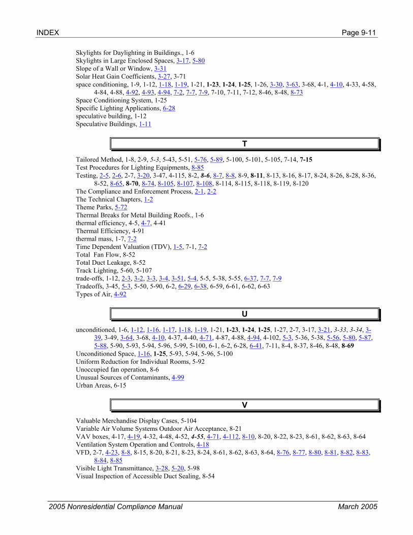
INDEX Page 9-11
2005 Nonresidential Compliance Manual March 2005
Skylights for Daylighting in Buildings., 1-6 Skylights in Large Enclosed Spaces, 3-17, 5-80 Slope of a Wall or Window, 3-31 Solar Heat Gain Coefficients, 3-27, 3-71 space conditioning, 1-9, 1-12, 1-18, 1-19, 1-21, 1-23, 1-24, 1-25, 1-26, 3-30, 3-63, 3-68, 4-1, 4-10, 4-33, 4-58,
4-84, 4-88, 4-92, 4-93, 4-94, 7-2, 7-7, 7-9, 7-10, 7-11, 7-12, 8-46, 8-48, 8-73 Space Conditioning System, 1-25 Specific Lighting Applications, 6-28 speculative building, 1-12 Speculative Buildings, 1-11
T
Tailored Method, 1-8, 2-9, 5-3, 5-43, 5-51, 5-76, 5-89, 5-100, 5-101, 5-105, 7-14, 7-15 Test Procedures for Lighting Equipments, 8-85 Testing, 2-5, 2-6, 2-7, 3-20, 3-47, 4-115, 8-2, 8-6, 8-7, 8-8, 8-9, 8-11, 8-13, 8-16, 8-17, 8-24, 8-26, 8-28, 8-36,
8-52, 8-65, 8-70, 8-74, 8-105, 8-107, 8-108, 8-114, 8-115, 8-118, 8-119, 8-120 The Compliance and Enforcement Process, 2-1, 2-2 The Technical Chapters, 1-2 Theme Parks, 5-72 Thermal Breaks for Metal Building Roofs., 1-6 thermal efficiency, 4-5, 4-7, 4-41 Thermal Efficiency, 4-91 thermal mass, 1-7, 7-2 Time Dependent Valuation (TDV), 1-5, 7-1, 7-2 Total Fan Flow, 8-52 Total Duct Leakage, 8-52 Track Lighting, 5-60, 5-107 trade-offs, 1-12, 2-3, 3-2, 3-3, 3-4, 3-51, 5-4, 5-5, 5-38, 5-55, 6-37, 7-7, 7-9 Tradeoffs, 3-45, 5-3, 5-50, 5-90, 6-2, 6-29, 6-38, 6-59, 6-61, 6-62, 6-63 Types of Air, 4-92
U
unconditioned, 1-6, 1-12, 1-16, 1-17, 1-18, 1-19, 1-21, 1-23, 1-24, 1-25, 1-27, 2-7, 3-17, 3-21, 3-33, 3-34, 3-39, 3-49, 3-64, 3-68, 4-10, 4-37, 4-40, 4-71, 4-87, 4-88, 4-94, 4-102, 5-3, 5-36, 5-38, 5-56, 5-80, 5-87, 5-88, 5-90, 5-93, 5-94, 5-96, 5-99, 5-100, 6-1, 6-2, 6-28, 6-41, 7-11, 8-4, 8-37, 8-46, 8-48, 8-69
Unconditioned Space, 1-16, 1-25, 5-93, 5-94, 5-96, 5-100 Uniform Reduction for Individual Rooms, 5-92 Unoccupied fan operation, 8-6 Unusual Sources of Contaminants, 4-99 Urban Areas, 6-15
V
Valuable Merchandise Display Cases, 5-104 Variable Air Volume Systems Outdoor Air Acceptance, 8-21 VAV boxes, 4-17, 4-19, 4-32, 4-48, 4-52, 4-55, 4-71, 4-112, 8-10, 8-20, 8-22, 8-23, 8-61, 8-62, 8-63, 8-64 Ventilation System Operation and Controls, 4-18 VFD, 2-7, 4-23, 8-8, 8-15, 8-20, 8-21, 8-23, 8-24, 8-61, 8-62, 8-63, 8-64, 8-76, 8-77, 8-80, 8-81, 8-82, 8-83,
8-84, 8-85 Visible Light Transmittance, 3-28, 5-20, 5-98 Visual Inspection of Accessible Duct Sealing, 8-54

Page 9-12 INDEX
2005 Nonresidential Compliance Manual March 2005
W
warehouse, 1-12, 1-18, 1-23, 1-25, 3-20, 3-39, 5-84, 5-87, 5-88 Warren-Alquist Act, 1-28, 7-1 water treatment plant, 1-26 well cavity ratio, 5-21, 5-22, 5-23, 5-24, 5-25, 5-27, 5-30 West William Way, 6-16 What’s New for 2005, 1-5, 3-4 When Are Acceptance Tests Required, 8-3 Whole Building, 1-22, 7-8, 7-14 Whole Building Compliance, 7-8, 7-14 Why California Needs Energy Standards, 1-2 Why Test for Acceptance, 8-5 Wildlife Preserves, 6-15 Window Prescriptive Requirements, 3-65, 3-66
Z
zonal control, 1-7 Zone Reheat, Recool and Air Mixing, 4-94

2005 Nonresidential Compliance Forms September 2005
Appendix A Compliance & Acceptance Forms
Certificate of Compliance Forms and Worksheets
Envelope Mechanical Lighting Outdoor Lighting ENV-1-C Certificate of Compliance ENV-2-C Envelope Component Method ENV-3-C Overall Envelope Method ENV-4-C Skylight Area Support Worksheet
MECH-1-C Certificate of Compliance MECH-2-C Air System, Water Side System, Service Hot Water & Pool Requirements MECH-3-C Mechanical Ventilation MECH-4-C HVAC Misc. Prescriptive Requirements
LTG-1-C Certificate of Compliance LTG-2-C Indoor Lighting Schedule LTG-3-C Portable Lighting Worksheet LTG-4-C Lighting Controls Credit Worksheet LTG-5-C Indoor Lighting Power Allowance LTG-6-C Tailored Method Worksheet LTG-7-C Room Cavity Ratio Worksheet LTG-8-C Common Lighting Systems Method LTG-9-C Line Voltage Track Lighting Worksheet
OLTG-1-C Certificate of Compliance OLTG-2-C Lighting Compliance Summary OLTG-3-C Illuminated Area Calculation Worksheet OLTG-4-C Sign Lighting Compliance
Certificate of Acceptance Forms and Worksheets
Mechanical Outdoor Lighting MECH-1-A Certificate of
Acceptance MECH-2-A Ventilation Systems – Variable and Constant Volume MECH-3-A Packaged HVAC Systems MECH-4-A Economizer MECH-5-A Air Distribution MECH-6-A Demand Control Ventilation MECH-7-A Supply Fan VFD MECH-8-A Hydronic Systems Control
LTG-1-A Certificate of Acceptance LTG-2-A Lighting Controls LTG-3-A Automatic Daylighting

2005 Nonresidential Compliance Forms April 2005
____________________________________________________ 2005 Compliance Forms
2005 Nonresidential Compliance Forms April 2005
______________________________________________________ Envelope Forms - Compliance

2005 Nonresidential Compliance Forms April 2005
CERTIFICATE OF COMPLIANCE (Part 1 of 2) ENV-1-C PROJECT NAME DATE
PROJECT ADDRESS PRINCIPAL DESIGNER-ENVELOPE TELEPHONE
DOCUMENTATION AUTHOR TELEPHONE
____________________
Building Permit #
____________________ Checked by/Date
Enforcement Agency Use
GENERAL INFORMATION
DATE OF PLANS BUILDING CONDITIONED FLOOR AREA CLIMATE ZONE
BUILDING TYPE NONRESIDENTIAL HIGH-RISE RESIDENTIAL HOTEL/MOTEL GUEST
RELOCATABLE – Indicate: specific climate – list ____________________ , or all climates
PHASE OF CONSTRUCTION NEW CONSTRUCTION ADDITION ALTERATION UNCONDITIONED (file
METHOD OF ENVELOPE COMPLIANCE
COMPONENT OVERALL ENVELOPE
SUPPORTING FORMS SUBMITTED
ENV-2-C (Component) ENV-3-C (Overall Envelope) ENV-4-C (Skylight Worksheet)
STATEMENT OF COMPLIANCE This Certificate of Compliance lists the building features and performance specifications need to comply with Title 24, Parts 1 and 6 of the California Code of Regulations. This certificate applies only to building envelope requirements. The documentation preparer hereby certifies that the documentation is accurate and complete. DOCUMENTATION AUTHOR SIGNATURE DATE The Principal Envelope Designer hereby certifies that the proposed building design represented in this set of construction documents is consistent with the other compliance forms and worksheets, with the specifications, and with any other calculations submitted with this permit application. The proposed building has been designed to meet the envelope requirements contained in sections 110, 116 through 118, and 140, 142, 143 or 149 of Title 24, Part 6. Please check one:
I hereby affirm that I am eligible under the provisions of Division 3 of the Business and Professions Code to sign this document as the person responsible for its preparation; and that I am licensed in the State of California as a civil engineer or mechanical engineer, or I am a licensed architect.
I affirm that I am eligible under the provisions of Division 3 of the Business and Professions Code by section 5537.2 or 6737.3 to sign this document as the person responsible for its preparation; and that I am a licensed contractor performing this work.
I affirm that I am eligible under Division 3 of the Business and Professions Code to sign this document because it pertains to a structure or type of work described as exempt pursuant to Business and Professions Code Sections 5537, 5538 and 6737.1.
(These sections of the Business and Professions Code are printed in full in the Nonresidential Manual.) PRINCIPAL ENVELOPE DESIGNER-NAME SIGNATURE DATE LIC. # ENVELOPE MANDATORY MEASURES Indicate location on plans of Note Block for Mandatory Measures ______________________________________ INSTRUCTIONS TO APPLICANT ENVELOPE COMPLIANCE & WORKSHEETS (check box if worksheet is included)
For detailed instructions on the use of this and all Energy Efficiency Standards compliance forms, please refer to the Nonresidential Manual published by the California Energy Commission.
ENV-1-C Certificate of Compliance. Required on plans for all submittals. Part 2 may be incorporated in schedules on plans.
ENV-2-C Use with the Envelope Component compliance method.
ENV-3-C Use with the Overall Envelope compliance method.
ENV-4-C Optional. Use for the minimum skylight requirements for large enclosed spaces.

2005 Nonresidential Compliance Forms April 2005
CERTIFICATE OF COMPLIANCE (Part 2 of 2) ENV-1-C PROJECT NAME DATE OPAQUE SURFACES Location/Comments NOTES TO FIELD
Surface Insulation Actual Condition Joint App (e.g., Suspended For Building Type Area U-factor Cavity Continuou Azimuth Tilt Status* IV Reference Ceiling, Demising, etc.) Use Only
* N, E, A, (New, Existing, Altered)
FENESTRATION SURFACES
More than or equal to10,000 ft² of site-built fenestration area must include a label certificate issued by NFRC or provide a CEC Default Label Certificate using the default U-factors from Standards Tables 116-A and B. Certificate shall be filed in the contractor’s project office during construction and in the building manager’s office after construction.
A B C D E F G H I J K
Fen. #
Fenestration Type Area Azimuth
U-
factor U-factor Type1
Fenes-tration SHGC
SHGC Type2
Condition Status3
Location / Comments
NOTES TO FIELD – For Bldg. Dept. Use Only
1 U-factor Type: D, A or N (D for Default Table from Section 116, A for ACM Manual Appendix Default Table, or N for NFRC Labeled) 2 SHGC Type: D, C or N (D for Default Table from Section 116, C for Center of Glass, or N for NFRC). 3 Condition Status: N, E, or A (New, Existing, or Altered).. EXTERIOR SHADING
Window Overhang Fenestration No.
Exterior Shade Type SHGC Height Width Length Height LExt. RExt.
MINIMUM SKYLIGHT AREA FOR LARGE ENCLOSED SPACES
The proposed building contains an enclosed space with floor area greater than 25,000 ft2, a ceiling height greater than 15 feet, and an LPD for general lighting of at least 0.5 W/ft2. If this box is checked, ENV-4-C must be filled out.
NOTES TO FIELD - For Building Department Use Only

2005 Nonresidential Compliance Forms June 2005
ENVELOPE COMPONENT METHOD (Part 1 of 2) ENV-2-C PROJECT NAME DATE WINDOW AREA CALCULATION
A. DISPLAY PERIMETER FT × 6 FT = SF DISPLAY AREA
B. GROSS EXTERIOR WALL AREA
SF × 0.40 = SF 40% of GROSS EXTERIOR WALL AREA
C. ENTER LARGER OF A OR B SF MAXIMUM STANDARD AREA
D. ENTER PROPOSED WINDOW AREA SF PROPOSED WINDOW AREA
If the PROPOSED WINDOW AREA is greater than the MAXIMUM STANDARD AREA then the envelope component method may not be used.
E. WINDOW WALL RATIO = Proposed Window Area Divided by Gross Exterior Wall Area =
F. WEST DISPLAY PERIMETER FT × 6 FT = SF WEST DISPLAY AREA
G. WEST EXTERIOR WALL AREA SF × 0.40 = SF 40% of WEST EXTERIOR WALL AREA
H. ENTER THE LARGER OF F AND G SF MAXIMUM STANDARD WEST AREA
I. ENTER PROPOSED WEST WINDOW AREA SF PROPOSED WEST WINDOW AREA
If the PROPOSED WEST WINDOW AREA is greater than the MAXIMUM STANDARD WEST AREA then the envelope component method may not b d
J. WEST WINDOW WALL RATIO = Proposed West Window Area Divided by West Exterior Wall Area =
SKYLIGHT AREA CALCULATION
A. ATRIUM or SKYLIGHT HEIGHT FT
GROSS ROOF AREA
STANDARD ALLOWED
SKYLIGHT AREA
B. IF Atrium/Skylight Height in A ≤ 55 FT SF × 0.05 = SF
C. IF Height in A > 55 FT SF × 0.10 = SF
D. PROPOSED SKYLIGHT AREA SF
If the PROPOSD SKYLIGHT AREA is greater than the STANDARD ALLOWED SKYLIGHT AREA then the envelope component method may not be used.
SKYLIGHTS SKYLIGHT NAME SKYLIGHT GLAZING U-FACTOR SOLAR HEAT GAIN COEFFICIENT
(e.g., Sky-1, Sky-2)
With Curb
With No
Curb
Plastic
# OF
PANES PROPOSED ALLOWED PROPOSED ALLOWED
RELOCATABLE PUBLIC SCHOOL BUILDINGS - See §143(a)8 in the Energy Standards
For Specific Climate Zone, use Table 143-A - Prescriptive Envelope Criteria.
Specific Climate Zone Metal Identification Label – Place two labels on each relocatable building and indicate on the building plans.
For Any (All) Climate Zone, use Table 143-C - Prescriptive Envelope Criteria.
Any (All) Climate Zone Metal Identification Label - Place two labels on each relocatable building and indicate on the building plans.

2005 Nonresidential Compliance Forms June 2005
ENVELOPE COMPONENT METHOD (Part 2 of 2) ENV-2-C PROJECT NAME DATE
COOL ROOFS - LOW-SLOPED - See Section 3.4 in the NRM and §118(i)3 and §143(a)1 in the Energy Standards for further description about exterior roofs and mandatory requirements for Cool Roofs.
CHECK APPLICABLE BOXES Option 1- Tested - Initial Thermal Emittance ≥ 0.75 and Intial Solar Reflectance ≥ 0.70
Proposed emittance and reflectance must be ≥ the standard when tested with CRRC-1. Proposed Standard
1. Enter proposed initial thermal emittance, εinitial ≥ 0.75 If proposed ≥ to the Standard then it complies.
2. Enter the proposed initial solar reflectance, ρinitial ≥ 0.70 If proposed ≥ to the Standard then it complies.
3. When applying Liquid Field Applied Coatings, the coating must be applied with a minimum dry mil thickness of 20 mils across the entire roof surface and meet minimum performance requirements listed in §118(i)3 and Table 118-C. Select the applicable coating:
Aluminum-Pigmented Asphalt Roof Coating
Cement-Based Roof Coating Other _______________________________________________
Option 2 - CRRC-1 Tested - Initial Thermal Emittance < 0.75 Proposed initial thermal emittance < 0.75 when tested with CRRC-1. Proposed Standard
1. Enter proposed initial thermal emittance, εinitial < 0.75 Go to line 2. Insert εinitial value in calculation.
2. Enter the initial solar reflectance, ρinitial 0.70 + [0.34 X (0.75 - εinitial)] Standard
ρinitial =
3. To apply Liquid Field Applied Coatings, the coating must be applied with a minimum dry mil thickness of 20 mils across the entire roof surface and meet minimum performance requirements listed in §118(i)3 and Table 118-C. Select the applicable coating:
Aluminum-Pigmented Asphalt Roof Coating
Cement-Based Roof Coating Other _______________________________________________
CRRC-1 Label Attached to Submittal (Note if no CRRC-1 label is available, this compliance method can not be used). OPAQUE SURFACES
ASSEMBLY NAME TYPE INSULATION R-VALUE* ASSEMBLY U-FACTOR*
(e.g. Roof-1, Wall-1, Floor-, Soffits, etc…)
(e.g. Roof, Wall, Floor, demising,
etc…) HEAT
CAPACITY PROPOSEDMINIMUM ALLOWED PROPOSED
Joint Appendix IV REF
MAXIMUM ALLOWED
* For each assembly type, meet the minimum insulation R-value or the maximum assembly U-factor. WINDOWS
ORIENTATION Fenestration WINDOW NAME U-FACTOR # OF Fen. PROPOSED RSHG PROP. ALLOWED
(e.g., Window-1, Window-2) N E S W PROP. ALLOW. PANES SHGC* H V H/V OHF RSHG RSHG
* From Fenestration Surfaces ENV-1-C, Part 2, Column G, or when Column H has a “C” identifier, calculate using the center of glass value SHGCc in SHGCFEN = .08 + (.86 x SHGCc) and enter value.

2005 Nonresidential Compliance Forms April 2005
OVERALL ENVELOPE METHOD (Part 1 of 7) ENV-3-C PROJECT NAME DATE
WINDOW AREA CALCULATION
A. DISPLAY PERIMETER FT × 6 FT = SF DISPLAY AREA
B. GROSS EXTERIOR WALL AREA
SF × 0.40 = SF 40% of GROSS EXTERIOR WALL AREA
C. ENTER LARGER OF A OR B SF MAXIMUM STANDARD AREA
D. ENTER PROPOSED WINDOW AREA SF PROPOSED AREA
E. WINDOW WALL RATIO = Proposed Window Area Divided by Gross Exterior Wall Area =
F. WEST DISPLAY PERIMETER FT × 6 FT = SF WEST DISPLAY AREA
G. WEST EXTERIOR WALL AREA SF × 0.40 = SF 40% of WEST EXTERIOR WALL AREA
H. ENTER THE LARGER OF F AND G SF MAXIMUM STANDARD WEST AREA
I. ENTER PROPOSED WEST WINDOW AREA SF PROPOSED WEST WINDOW AREA
J. WEST WINDOW WALL RATIO = Proposed West Window Area Divided by West Exterior Wall Area =
Combined Values for North, East and South Walls
K. N/E/S DISPLAY PERIMETER (A - F) FT × 6 FT = SF N/E/S DISPLAY AREA
L. N/E/S EXTERIOR WALL AREA (B - G) SF × 0.40 = SF 40% N/E/S AREA
M. ENTER LARGER OF K OR L SF MAXIMUM STANDARD N/E/S AREA
N. PROPOSED N/E/S WINDOW AREA (A - I) SF PROPOSED N/E/S AREA
Window adjustment
O. IF D>C and/or if I>H, PROCEED TO THE CALCULATION STEPS 1 OR 2 BELOW, AS APPROPRIATE, FOR WINDOW AREA ADJUSTMENT. IF NOT, GO TO THE SKYLIGHT AREA TEST ON PAGE
1. IF I<H: Use the calculated Window Adjustment Factor (WAF) for all walls. MAX. STANDARD AREA
(from C) PROPOSED
WINDOW AREA (from D) WINDOW
ADJUSTMENT FACTOR ÷ =
GO TO PART 6 TO CALCULATE ADJUSTED AREAS
2. IF I>H: Calculate one Window Adjustment Factor (WAF) for the West wall, and a second WAF for all other orientations. a. Calculate the WAF for the West wall.
MAX. STANDARD WEST AREA (from H)
PROPOSED WEST AREA (from I)
WEST WINDOW ADJUSTMENT FACTOR
÷ =
b. Calculate the WAF for the North, East and South walls.
MAX. STANDARD N/E/S AREA (from M)
PROPOSED N/E/S AREA (from N)
N/E/S WINDOW ADJUSTMENT FACTOR
÷ =
GO TO PART 6 TO CALCULATE ADJUSTED AREAS
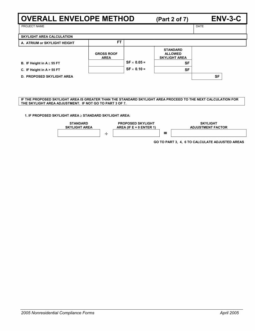
2005 Nonresidential Compliance Forms April 2005
OVERALL ENVELOPE METHOD (Part 2 of 7) ENV-3-C PROJECT NAME DATE SKYLIGHT AREA CALCULATION
A. ATRIUM or SKYLIGHT HEIGHT FT
GROSS ROOF AREA
STANDARD ALLOWED
SKYLIGHT AREA
B. IF Height in A ≤ 55 FT SF × 0.05 = SF
C. IF Height in A > 55 FT SF × 0.10 = SF
D. PROPOSED SKYLIGHT AREA SF
IF THE PROPOSED SKYLIGHT AREA IS GREATER THAN THE STANDARD SKYLIGHT AREA PROCEED TO THE NEXT CALCULATION FOR THE SKYLIGHT AREA ADJUSTMENT. IF NOT GO TO PART 3 OF 7.
1. IF PROPOSED SKYLIGHT AREA ≥ STANDARD SKYLIGHT AREA:
STANDARD SKYLIGHT AREA
PROPOSED SKYLIGHT AREA (IF E = 0 ENTER 1)
SKYLIGHT ADJUSTMENT FACTOR
÷ =
GO TO PART 3, 4, 6 TO CALCULATE ADJUSTED AREAS

2005 Nonresidential Compliance Forms April 2005
OVERALL ENVELOPE METHOD (Part 3 of 7) ENV-3-C PROJECT NAME DATE
OVERALL HEAT LOSS
A B C D E F G H PROPOSED STANDARD ASSEMBLY NAME HEAT UA AREA2 UA (e.g. Wall-1, Floor-1) AREA CAPACITY U-FACTOR1
Joint Appendix IV REF. (B × D) (Adjusted) U-FACTOR (F × G)
N/A
N/A
N/A
N/A
N/A
N/A
N/A
N/A
N/A
N/A
N/A
1 In climate zones 1 and 16 the insulating R-value of continuous insulation materials installed above the roof waterproof membrane must be multiplied by 0.8 before choosing the table column for determining assembly U-factor. See footnotes for Tables IV.1 through IV.7 in the Joint Appendices. 2 If Window and/or Skylight Area Adjustment is required, use adjusted areas from Part 7of 7.
TOTAL TOTAL

2005 Nonresidential Compliance Forms April 2005
OVERALL ENVELOPE METHOD (Part 4 of 7) ENV-3-C PROJECT NAME DATE OVERALL HEAT GAIN FROM CONDUCTION
A B C D E F G H I J PROPOSED STANDARD ASSEMBLY NAME (e.g. Wall-1, Floor-1)
AREA TEMP
FACTOR HEAT
CAPACITYU -
FACTOR1
Joint App. IV
REF.
HEAT GAIN
(B ×C ×E) AREA2
(Adjusted) U -
FACTOR TEMP
FACTORHEAT GAIN
(G ×H ×I)
N/A
N/A
N/A
N/A
N/A
N/A
N/A
N/A
N/A
N/A
N/A
SUBTOTAL SUBTOTAL
1 In climate zones 1 and 16 the insulating R-value of continuous insulation materials installed above the roof waterproof membrane must be multiplied by 0.8 before choosing the table column for determining assembly U-factor. See footnotes for Tables IV.1 through IV.7 in the Joint Appendices.
2 If Window and/or Skylight Area Adjustment is required, use adjusted areas from Part 7 of 7.
Subtotals are entered under “Subtotal” in COLUMNS I and M
of ENV-3-C, Part 6 of 7.

2005 Nonresidential Compliance Forms April 2005
OVERALL ENVELOPE METHOD (Part 5 of 7) ENV-3-C PROJECT NAME DATE ROOF ABSORPTANCE CALCULATION: Use this table to determine the value of the absorptance for the proposed design, αprop
CHECK APPLICABLE BOXES Case 1 - Proposed YES NO 1. CRRC-1 Certified? Go to 2. Go to 8.
2. Is the thermal emittance ≥ 0.75? Go to 3. Go to 5. 3. Enter the initial reflectance ρinit value ρRi,prop = Go to 4. Insert value in calculation.
4. Calculate αprop = 0.94-0.7ρRi,prop αprop = Enter calculated value in Column F below.
Case 2 - CRRC-1 Tested
5.Enter initial reflectance & emittance values from CRRC-1 ρinit = εinit = Go to 6. Insert values in calculation
6. Calculate ρRi,prop = -0.448 + 1.121 ρinit + 0.524 εinit ρRi,prop = Go to 7. Insert value in calculalion 7. Calculate αprop = 0.94-0.7ρRi,prop αprop = Enter calculated value in Column F below. Case 3 - Not CRRC-1 Tested YES NO 8. Is the roof a nonresidential low-sloped? (2:12 or less) Go to 9. Go to 10. 9. Use the default values for absorptance, αprop αprop = 0.87 Enter default value in Column F below. 10. Use the default values for absorptance, αprop αprop = 0.73 Enter default value in Column F below. Standard absorptance values αstd, for Column J are either For nonresidential low-sloped roofs αstd = 0.45 Enter standard value in Column F below. For nonresidential high-sloped roofs αstd = 0.73 Enter standard value in Column F below. OVERALL HEAT GAIN FROM RADIATION OPAQUE SURFACES
A B C D E F G H I J K PROPOSED STANDARD
ASSEMBLY NAME SOLAR WEIGHT U - Absorp HEAT GAIN AREA U- Absorp HEAT GAIN (e.g. Roof-1) AREA FACTOR FACTOR FACTOR α (B×CxD×ExF) (Adjusted) FACTOR α (C×DxH×IxJ)
SUBTOTAL
Subtotals are entered under “Subtotal” in COLUMNS I and M of ENV-3-C, Part 6 of 7. SUBTOTAL

2005 Nonresidential Compliance Forms April 2005
OVERALL ENVELOPE METHOD (Part 6 of 7) ENV-3-C PROJECT NAME DATE OVERALL HEAT GAIN FROM RADIATION FENESTRATION SURFACES
A B C D E F G H I J K L M PROPOSED STANDARD WINDOW/SKYLIGHT
NAME WEIGHTING
OVERHANG
HEAT GAIN2 (BxCx
AREA
RSHG or
HEAT GAIN
(e.g Window-1, Sky-1) FACTOR AREA
S
OLA
R
FAC
TOR
SHGC1 H V H/V OHF DxExH) (Adjusted)3 SHGC4
SO
LAR
FA
CTO
R
(B×J×K ×L)
N/A N/A N/A N/A
N/A N/A N/A N/A
N/A N/A N/A N/A
N/A N/A N/A N/A
N/A N/A N/A N/A
Part 4 Subtotal Part 4 Subtotal Part 5 Subtotal Part 5 Subtotal Part 6 Subtotal Part 6 Subtotal
1 From Fenestration Surfaces ENV-1-C, Part 2, column G, or when Column H has a “C” identifier, calculate using the center of glass value SHGCc in SHGCfen = .08 + (0.86XSHGCc) and enter value. 2 Proposed Heat Gain, Column I may be no greater than Standard Heat Gain Column M. 3 If Window and/or Skylight Area Adjustment is required, use adjusted areas from Part 7 of 7. 4 Only SHGC is used for Skylights
TOTAL
TOTAL

2005 Nonresidential Compliance Forms April 2005
OVERALL ENVELOPE METHOD (Part 7 of 7) ENV-3-C PROJECT NAME DATE WINDOW AREA ADJUSTMENT CALCULATIONS
Note: Putting the letters at the top of the columns in boxes is completely inconsistent with all the other pages
CHECK IF NOT APPLICABLE (see Part 1 of 7)
E F G
A B C D WINDOW ADJUSTMENT
ADJUSTED WINDOW
ADJUSTED WALL
WALL NAME ORIENTATION GROSS DOOR WINDOW FACTOR AREA AREA (e.g. Wall-1, Wall-2) N E S W AREA AREA AREA (From Part 1) (D×E) B-(F+C)
TOTALS: SKYLIGHT AREA ADJUSTMENT CALCULATIONS
CHECK IF NOT APPLICABLE (see Part 2 of 7)
A B C D E F
ROOF NAME GROSS SKYLIGHT SKYLIGHT ADJUSTMENT
FACTOR
ADJUSTED SKYLIGHT AREA
ADJUSTED ROOF AREA
(e.g. Roof-1, Roof-2) AREA AREA (From Part 1) (C×D) (B - E)
TOTALS:
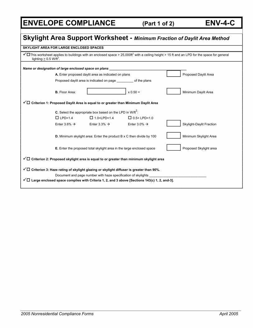
2005 Nonresidential Compliance Forms April 2005
ENVELOPE COMPLIANCE (Part 1 of 2) ENV-4-C
Skylight Area Support Worksheet - Minimum Fraction of Daylit Area Method SKYLIGHT AREA FOR LARGE ENCLOSED SPACES
This worksheet applies to buildings with an enclosed space > 25,000ft2 with a ceiling height > 15 ft and an LPD for the space for general lighting > 0.5 W/ft2.
Name or designation of large enclosed space on plans __________________________________________
A. Enter proposed daylit area as indicated on plans Proposed Daylit Area
Proposed daylit area is indicated on page _________ of the plans
B. Floor Area: x 0.50 = Minimum Daylit Area
Criterion 1: Proposed Daylit Area is equal to or greater than Minimum Daylit Area
C. Select the appropriate box based on the LPD in W/ft2:
LPD>1.4 1.0<LPD<1.4 0.5< LPD<1.0
Enter 3.6% Enter 3.3% Enter 3.0% Skylight-Daylit Fraction
D. Minimum skylight area: Enter the product B x C then divide by 100 Minimum Skylight Area
E. Enter the proposed total skylight area in the large enclosed space Proposed Skylight area
Criterion 2: Proposed skylight area is equal to or greater than minimum skylight area
Criterion 3: Haze rating of skylight glazing or skylight diffuser is greater than 90%. Document and page number with haze specification of skylights _______________________________
Large enclosed space complies with Criteria 1, 2, and 3 above [Sections 143(c) 1, 2, and-3].

2005 Nonresidential Compliance Forms April 2005
ENVELOPE COMPLIANCE (Part 2 of 2) ENV-4-C
Skylight Area Support Worksheet - Minimum Effective Aperture Method This worksheet applies to buildings with an enclosed space > 25,000ft2 with a ceiling height > 15ft and an LPD for the space for general lighting > 0.5 W/ft2. Name or designation of large enclosed space on plans __________________________________________ F. Enter proposed daylit area as indicated on plans SF Proposed Daylit Area
Proposed daylit area is indicated on page _________ of the plans
G. Floor Area: SF x 0.50 = SF Minimum Daylit Area
Criterion 1: Proposed Daylit Area is equal to or greater than Minimum Daylit Area H. Select the appropriate box for LPD: LPD>1.4 1.0<LPD<1.4 0.5< LPD<1.0
Enter 1.2% Enter 1.1% Enter 1.0% Min Effective Aperture
I. Skylight Visible Light Transmittance (VLTS) VLTs is from manufacturers specifications.
VLTS
J. Well Cavity Ratio. Select one of the well types, fill in columns A, B, and C and calculate the WCR with the appropriate equation below.
A B C Well Height Well Length Well Width
Rectangular. Wells:
note
WCR
Well Height Well Perimeter Well Area
Non-Rectangular Wells:
WCR
K. Average Well Wall Reflectance (%),ρ Wall ρ
L. Well Efficiency (from equation in Section 5.6 of the Nonresidential Manual or from nomograph, Figure 146-A)
Well Efficiency
M. Calculate Minimum Skylight Area:
AS = Effective Aperture (H) x Daylit Area (F)
)()(85.0 LencyWellEfficiIVLT ×× Minimum Skylight Area
N. Enter the Proposed Skylight Area. Proposed Skylight Area
Criterion 2: Proposed skylight area is equal to or greater than minimum skylight area
Criterion 3: Haze rating of skylight glazing or skylight diffuser is greater than 90%. Document and page number with haze specification of skylights _______________________________
Large enclosed space complies with Criteria 1, 2, and 3 above [Sections 143(c) 1, 2, and-3].
( )
×
×=
widthwelllength well widthwell+length wellheight well5WCR
××
=area well
perimeter wellheight well2.5WCR

2005 Nonresidential Compliance Forms April 2005
CEC DEFAULT U-FACTOR AND SHGC LABEL CERTIFICATE FORM FC-1 PROJECT INFORMATION
PROJECT NAME: DATE:
PROJECT ADDRESS:
CEC DEFAULT U-FACTOR AND SHGC LABEL CERTIFICATE
(Use only for Site-Built Fenestration Product Lines)
Method 1- CEC Default Certificate may be used for site-built glazing installed in all non-residential buildings.
U-factors and SHGC are derived from the California Energy Commission Fenestration Default U-factors and SHGC Default Table based on data reported below.
U-factor = ___ SHGC = ___
This Fenestration Product Line meets the air infiltration requirements of Section 116(a) 1, 2005 California Energy Efficiency Standards for Residential and Nonresidential Buildings.
PRODUCT LINE INFORMATION (Complete a separate Default Label Certificate for each fenestration product line)
Total Number of units for this product line: Total square footage of this product line:
Elevation drawing page: Fenestration (window & door) schedule page:
Location(s) on building: S, N, E, W (Enter appropriate orientation(s))
Total Fenestration Area (ft2) on project:
Method 1 - DEFAULT FENESTRATION U-FACTOR AND SHGC FROM STANDARD TABLES 116-A AND 116-B of the 2005 California Energy Efficiency Standards for Residential and Nonresidential Buildings.
Frame Type Metal Metal Thermal Break (or Structural Glazing) Nonmetal
U-factor Table 116-A Product Type Operable Fixed Greenhouse, Garden Window Door Skylight
Glazing Type Single Pane Double Pane Default U-factor = Calculate U-factor adjustment. See U-factor Adjustment below.
SHGC Table 116-B Product Type Operable Fixed
SHGC Table 116-B Glazing Tint Clear Tint Default SHGC = (Insert default value here and in above gray box next to SHGC)
U-Factor Adjustment (See Table 116-A, Footnote 1 and 2)
Nonmetal-framed manufactured fenestration products with metal cladding must add 0.04 to the listed U-factor. Subtract 0.05 for spacers of 7/16 inch or wider
Subtract 0.05 for products certified by the manufacturer as low-E glazing.
Add 0.05 for products with dividers between panes if spacer is less than 7/16 inch wide.
Add 0.05 for products with true divided lite (dividers through the panes).
U-Factor Adjustment = (If applicable insert adjustment result in above gray box next to U-factor)
PERSON TAKING RESPONSIBILITY FOR FENESTRATION COMPLIANCE CONTACT PERSON:
Contact Person:
Company name and address:
Phone: Fax: Signature:

2005 Nonresidential Compliance Forms April 2005
CEC ALTERNATIVE DEFAULT U-FACTOR AND SHGC LABEL CERTIFICATE FC-2 PROJECT INFORMATION
PROJECT NAME: DATE:
PROJECT ADDRESS:
CEC ALTERNATIVE
DDEFAULT U-FACTOR AND SHGC LABEL CERTIFICATE
(Use only for Site-Built Fenestration Product Lines)
Method 2 - Alternative Default Certificate shall not be used for site-built fenestration in buildings with 10,000ft2 or more of site-built fenestration area.
U-factors and SHGC are derived from the California Energy Commission Fenestration Default U-factors and SHGC Default Table based on data reported below.
U-factor = ___ SHGC = ___
This Fenestration Product Line meets the air infiltration requirements of Section 116(a) 1, 2005 California Energy Efficiency Standards for Residential and Nonresidential Buildings.
PRODUCT LINE INFORMATION (Complete a separate Default Label Certificate for each fenestration product line) Total Number of units for this product line: Total square footage of this product line:
Elevation drawing page: Fenestration (window & door) schedule page:
Location(s) on building: S, N, E, W (Enter appropriate orientation(s))
Total Fenestration Area (ft2) on project:
Method 2 DEFAULT FENESTRATION U-FACTOR FROM ACM APPENDIX NI-2005 Table NI-1 and MANUFACTURER’S DOCUMENTATION FOR SHGCc.
Product Type Systems Glazed Wall Skylight with Curb Skylight without Curb
Frame Type Aluminum Aluminum Metal
Thermal Break Wood/Vinyl Reinforced Vinyl/
Aluminum Clad Wood Structural Glazing
Glazing Type and thickness
Single ⅛” Glass
Single ⅛” Acrylic/polycarb
Single ¼ ” Acrylic/polycarb
Double Glazing Triple- Glazing Quadruple-Glazing
Coating Emissivity 0.05 0.10 0.20 0.40 0.60
Coated Surfaces 2 or 3 2, 3, 4, or 5 2 or 3 and 4 or 5
Glazing Spacing 1/4” Airspace 1/2” Airspace
Gas Fill Between Panes Air Argon Krypton
CEC ALTERNATIVE DEFAULT FENESTRATION U-FACTOR = From Assembly U-Factors – ACM Appendix NI-2005 Table NI-1 (Insert value in above gray box next to U-factor)
DEFAULT SOLAR HEAT GAIN COEFFICIENT
SHGC for Center of Glass SHGCc = From Manufacturer’s Documentation (Insert value “SHGCc “ in equation below)
Calculate SHGC Fenestration Equation from 2005 Appendix NI-2005 (NI.1 Solar Heat Gain Coefficient)
SHGCfen = 0.08 + (0.86 x SHGCc) = (Insert calculated result value in above gray box next to SHGC)
ATTACHED MANUFACTURED DOCUMENTATION Manufacturer’s documentation must be attached showing the Product Type, Frame Type, Glazing Type, and SHGCc information needed to determine the Default U-factor and SHGC from the Applicable Table or equation.
PERSON TAKING RESPONSIBILITY FOR FENESTRATION COMPLIANCE CONTACT PERSON:
Contact Person:
Company name and address:
Phone: Fax: Signature:

2005 Nonresidential Compliance Forms April 2005
____________________________________________________ Mechanical Forms - Compliance

CERTIFICATE OF COMPLIANCE (Part 1 of 3) MECH-1-C PROJECT NAME DATE PROJECT ADDRESS
PRINCIPAL DESIGNER-MECHANICAL TELEPHONE Building Permit
DOCUMENTATION AUTHOR TELEPHONE Checked by/Date Enforcement Agency Use
GENERAL INFORMATION
DATE OF PLANS BUILDING CONDITIONED FLOOR AREA CLIMATE ZONE
BUILDING TYPE NONRESIDENTIAL HIGH RISE RESIDENTIAL HOTEL/MOTEL GUEST ROOM
PHASE OF CONSTRUCTION NEW CONSTRUCTION ADDITION ALTERATION UNCONDITIONED
(file affidavit)PROOF OF ENVELOPE COMPLIANCE PREVIOUS ENVELOPE PERMIT ENVELOPE COMPLIANCE ATTACHED STATEMENT OF COMPLIANCE This Certificate of Compliance lists the building features and performance specifications needed to comply with Title 24, Parts 1 and 6 of the California Code of Regulations. This certificate applies only to building mechanical requirements. The documentation preparer hereby certifies that the documentation is accurate and complete.
DOCUMENTATION AUTHOR SIGNATURE DATE
The Principal Mechanical Designer hereby certifies that the proposed building design represented in this set of construction documents is consistent with the other compliance forms and worksheets, with the specifications, and with any other calculations submitted with this permit application. The proposed building has been designed to meet the mechanical requirements contained in the applicable parts of Sections 100, 101, 102, 110 through 115, 120 through 125, 142, 144 and 145.
The plans & specifications meet the requirements of Part 6 (Sections 10-103a). The installation certificates meet the requirements of Part 6 (10-103a 3). The operation & maintenance information meets the requirements of Part 6 (10-103c).
Please check one: (These sections of the Business and Professions Code are printed in full in the Nonresidential Manual.)
I hereby affirm that I am eligible under the provisions of Division 3 of the Business and Professions Code to sign this document as the person responsible for its preparation; and that I am licensed in the State of California as a civil engineer or mechanical engineer, or I am a licensed architect.
I affirm that I am eligible under the exemption to Division 3 of the Business and Professions Code by Section 5537.2 or 6737.3 to sign this document as the person responsible for its preparation; and that I am a licensed contractor performing this work.
I affirm that I am eligible under the exemption to Division 3 of the Business and Professions Code to sign this document because it pertains to a structure or type of work described pursuant to Business and Professions Code sections 5537, 5538, and 6737.1.
PRINCIPAL MECHANICAL DESIGNER-NAME SIGNATURE DATE LIC. #
INSTRUCTIONS TO APPLICANT MECHANICAL COMPLIANCE & WORKSHEETS (check box if worksheet is included)
MECH-1-C Certificate of Compliance. Part 1 of 3, 2 of 3, 3 of 3 are required on plans for all submittals
MECH-2-C Certificate of Compliance. Part 1 of 3, 2 of 3, 3 of 3 are required for all submittals, but may be on plans.
MECH-3-C Certificate of Compliance are required for all submittals with mechanical ventilation, but may be on plans.
MECH-4-C Certificate of Compliance are required for all prescriptive submittals, but may be on plans.
2005 Nonresidential Compliance Forms September 2005

CERTIFICATE OF COMPLIANCE (Part 2 of 3) MECH-1-C
PROJECT NAME DATE
Designer: This form is to be used by the designer and attached to the plans. Listed below are all the acceptance tests for mechanical systems. The designer is required to check the boxes by all acceptance tests that apply and list all equipment that requires an acceptance test. If all equipment of a certain type requires a test, list the equipment description and the number of systems to be tested in parentheses. The NJ number designates the Section in the Appendix of the Nonresidential ACM Manual that describes the test. Also indicate the person responsible for performing the tests (i.e. the installing contractor, design professional or an agent selected by the owner). Since this form will be part of the plans, completion of this section will allow the responsible party to budget for the scope of work appropriately.
Building Departments: Systems Acceptance. Before occupancy permit is granted for a newly constructed building or space, or a new space-conditioning system serving a building or space is operated for normal use, all control devices serving the building or space shall be certified as meeting the Acceptance Requirements for Code Compliance. In addition a Certificate of Acceptance, MECH-1-A, Form shall be submitted to the building department that certifies plans, specifications, installation certificates, and operating and maintenance information meet the requirements of §10-103(b) and Title 24 Part 6. Test Description Test Performed By:
MECH-2-A: Ventilation System Acceptance Document • Variable Air Volume Systems Outdoor Air Acceptance • Constant Air Volume Systems Outdoor Air Acceptance
Test required on all New systems both New Construction and Retrofit. Equipment requiring acceptance testing____________________________________
MECH-3-A: Packaged HVAC Systems Acceptance Document
Test required on all New packaged systems both New Construction and Retrofit. Equipment requiring acceptance testing _____________________________________
MECH-4-A: Air-Side Economizer Acceptance Document
Test required on all new air-side economizers for both New Construction and Retrofit. Units with economizers that are installed at the factory and certified with the Commission do not require equipment testing but do require construction inspection. Equipment requiring acceptance testing ____________________________________
2005 Nonresidential Compliance Forms September 2005

CERTIFICATE OF COMPLIANCE (Part 3 of 3) MECH-1-C PROJECT NAME
DATE
Test Description Test Performed By: MECH-5-A: Air Distribution Acceptance Document
This test required If the unit serves 5,000 ft2 of space or less and 25% or more of the ducts are in nonconditioned or semiconditioned space like an attic. New systems that meet the above requirements. Retrofit systems that meet the above requirements and either extend ducts, replace ducts or replace the packaged unit. Equipment requiring acceptance testing _____________________________________
MECH-6-A : Demand Control Ventilation Acceptance Document
All new DCV controls installed on new or existing packaged systems must be tested. Equipment requiring acceptance testing _____________________________________
MECH-7-A: Supply Fan Variable Flow Control Acceptance Document All new VAV fan volume controls installed on new or existing systems must be tested. Equipment requiring acceptance testing _____________________________________
MECH-8-A: • Hydronic System Control Acceptance Document • Variable Flow Controls, Applies to chilled and hot water systems. • Automatic Isolation Controls, Applies to new boilers and chillers and the primary
pumps are connected to a common header. • Supply Water Temperature Reset Controls, Applies to new constant flow chilled and
hot water systems that have a design capacity greater than or equal to 500,000 Btu/hr.
• Water-loop Heat Pump Controls, Applies to all new waterloop heat pump systems where the combined loop pumps are greater than 5 hp.
• Variable Frequency Control, Applies to all new distribution pumps on new variable flow chilled, hydronic heat pump or condenser water systems where the pumps motors are greater than 5 hp.
Equipment requiring acceptance testing _____________________________________
2005 Nonresidential Compliance Forms April 2005

2005
Non
resi
dent
ial C
ompl
ianc
e Fo
rms
A
pril
2005
AIR
SYS
TEM
REQ
UIR
EMEN
TS
(Par
t 1 o
f 3)
M
ECH
-2-C
PRO
JEC
T N
AM
E:
DA
TE:
AIR
SYS
TEM
S, C
entr
al o
r Sin
gle
Zone
IT
EM o
r SYS
TEM
TA
G(S
)
MA
ND
ATO
RY
MEA
SUR
ES
T-24
Se
ctio
n R
efer
ence
on
Plan
s or
Spe
cific
atio
n1 H
eatin
g E
quip
men
t Effi
cien
cy
112(
a)
C
oolin
g E
quip
men
t Effi
cien
cy
112(
a)
H
eat P
ump
Ther
mos
tat
112(
b)
Fu
rnac
e C
ontro
ls
112(
c), 1
15(a
)
Nat
ural
Ven
tilat
ion
121(
b)
M
inim
um V
entil
atio
n 12
1(b)
VA
V M
inim
um P
ositi
on C
ontro
l 12
1(c)
Dem
and
Con
trol V
entil
atio
n 12
1(c)
Tim
e C
ontro
l 12
1(c)
, 122
(e)
S
etba
ck a
nd S
etup
Con
trol
122(
e)
O
utdo
or D
ampe
r Con
trol
122(
f)
Isol
atio
n Zo
nes
122(
g)
P
ipe
Insu
latio
n 12
3
Duc
t Ins
ulat
ion
124
PR
ESC
RIP
TIVE
MEA
SUR
ES
C
alcu
late
d H
eatin
g C
apac
ity2
144(
a &
b)
P
ropo
sed
Hea
ting
Cap
acity
2 14
4(a
& b
)
Cal
cula
ted
Coo
ling
Cap
acity
2 14
4(a
& b
)
Pro
pose
d C
oolin
g C
apac
ity2
144(
a &
b)
Fa
n C
ontro
l 14
4(c)
DP
Sen
sor L
ocat
ion
144(
c)
S
uppl
y P
ress
ure
Res
et (D
DC
onl
y)
144(
c)
S
imul
tane
ous
Hea
t/Coo
l 14
4(d)
Eco
nom
izer
14
4(e)
Hea
t and
Coo
l Air
Sup
ply
Res
et
144(
f)
Duc
t Sea
ling
144(
k)
1:
For
eac
h ce
ntra
l and
sin
gle
zone
air
syst
ems
(or g
roup
of s
imila
r uni
ts) f
ill in
the
refe
renc
e to
she
et n
umbe
r and
/or s
peci
ficat
ion
sect
ion
and
para
grap
h nu
mbe
r whe
re th
e re
quire
d fe
atur
es a
re d
ocum
ente
d. I
f a re
quire
men
t is
not a
pplic
able
, put
"N/A
" in
the
colu
mn.
2:
Not
requ
ired
for h
ydro
nic
heat
ing
or c
oolin
g. E
ither
ent
er v
alue
her
e or
put
in re
fere
nce
to p
lans
and
spe
cific
atio
ns p
er fo
otno
te 1
.

2005
Non
resi
dent
ial C
ompl
ianc
e Fo
rms
A
pril
2005
WA
TER
SID
E SY
STEM
REQ
UIR
EMEN
TS
(P
art 2
of 3
)
M
ECH
-2-C
PRO
JEC
T N
AM
E:
DA
TE:
WA
TER
2 SID
E SY
STEM
S: C
hille
rs, T
ower
s, B
oile
rs, H
ydro
nic
Loop
s IT
EM o
r SYS
TEM
TA
G(S
)
MA
ND
ATO
RY
MEA
SUR
ES
T-24
Se
ctio
n R
efer
ence
on
Plan
s or
Spe
cific
atio
n1 E
quip
men
t Effi
cien
cy
112(
a)
Pip
e In
sula
tion
123
PRES
CR
IPTI
VE M
EASU
RES
Cal
cula
ted
Cap
acity
14
4(a
& b
)
P
ropo
sed
Cap
acity
14
4(a
& b
)
To
wer
Fan
Con
trols
14
4(h)
To
wer
Flo
w C
ontro
ls
144(
h)
Var
iabl
e Fl
ow S
yste
m D
esig
n 14
4(j)
Chi
ller a
nd B
oile
r Iso
latio
n 14
4(j)
CH
W a
nd H
HW
Res
et C
ontro
ls
144(
j)
W
LHP
Isol
atio
n V
alve
s 14
4(j)
VS
D o
n C
HW
, CW
& W
LHP
Pum
ps >
5HP
14
4(j)
DP
Sen
sor L
ocat
ion
144(
j)
1:
For
eac
h ch
iller,
cool
ing
tow
er, b
oile
r, an
d hy
dron
ic lo
op (o
r gro
ups
of s
imila
r equ
ipm
ent)
fill i
n th
e re
fere
nce
to s
heet
num
ber a
nd/o
r spe
cific
atio
n se
ctio
n an
d pa
ragr
aph
num
ber
whe
re th
e re
quire
d fe
atur
es a
re d
ocum
ente
d. I
f a re
quire
men
t is
not a
pplic
able
, put
"N/A
" in
the
colu
mn.
2.
Wat
er s
ide
syst
ems
incl
ude
wet
sid
e sy
stem
s us
ing
othe
r liq
uids
suc
h as
gly
col o
r brin
e.

2005
Non
resi
dent
ial C
ompl
ianc
e Fo
rms
Apr
il 20
05
SER
VIC
E H
OT
WA
TER
& P
OO
L R
EQU
IREM
ENTS
(P
art 3
of 3
)
MEC
H-2
-C
PRO
JEC
T N
AM
E:
DA
TE:
Serv
ice
Hot
Wat
er, P
ool H
eatin
g IT
EM o
r SYS
TEM
TA
G(S
)
MA
ND
ATO
RY
MEA
SUR
ES
T-24
Se
ctio
n R
efer
ence
on
Plan
s or
Spe
cific
atio
n1 W
ater
Hea
ter C
ertif
icat
ion
§113
(a)
W
ater
Hea
ter E
ffici
ency
§1
13 (b
)
Ser
vice
Wat
er H
eatin
g In
stal
latio
n §1
13 (c
)
Poo
l and
Spa
Effi
cien
cy a
nd C
ontro
l §1
14 (a
)
Poo
l and
Spa
Inst
alla
tion
§114
(b)
P
ool H
eate
r – N
o P
ilot L
ight
§1
15 (c
)
Spa
Hea
ter –
No
Pilo
t Lig
ht
§115
(d)
1:
For
eac
h w
ater
hea
ter,
pool
hea
t and
dom
estic
wat
er lo
op (o
r gro
ups
of s
imila
r equ
ipm
ent)
fill i
n th
e re
fere
nce
to s
heet
num
ber a
nd/o
r spe
cific
atio
n se
ctio
n an
d pa
ragr
aph
num
ber w
here
the
requ
ired
feat
ures
are
doc
umen
ted.
If a
requ
irem
ent i
s no
t app
licab
le, p
ut "N
/A" i
n th
e co
lum
n.

2005
Non
resi
dent
ial C
ompl
ianc
e Fo
rms
Apr
il 20
05
MEC
HA
NIC
AL
VEN
TILA
TIO
N A
ND
REH
EAT
MEC
H-3
-C
PR
OJE
CT
NA
ME
D
ATE
MEC
HA
NIC
AL
VEN
TILA
TIO
N (§
121(
b)2)
R
EHEA
T LI
MIT
ATI
ON
(§14
4(d)
)
AR
EA B
ASIS
O
CC
UPA
NC
Y B
ASIS
VAV
Min
imum
A
B
C
D
E F
G
H
I J
K
L M
N
Zone
/ S
yste
m
Con
ditio
n A
rea
(ft²)
CFM
pe
r ft²
Min
C
FM b
y A
rea
B x
C
Num
of
Peo
ple
CFM
pe
r P
erso
n
Min
C
FM b
y O
ccup
ant
E x
F
RE
Q’D
V.
A.
Max
of
D o
r G
Des
ign
Ven
tilat
ion
Air
cfm
30%
of
Des
ign
Zone
S
uppl
y cf
m
B x
0.4
cf
m/ft
²
Max
of
Col
umns
H
, J, K
, or
300
cf
m
Des
ign
min
imum
A
ir se
tpoi
nt
Tran
sfer
A
ir
15
15
15
15
15
15
15
15
15
15
15
15
Tota
ls
Col
umn
I Tot
al D
esig
n V
entil
atio
n A
ir
C
M
inim
um v
entil
atio
n ra
te p
er S
ectio
n §1
21, T
able
121
-A.
E B
ased
on
fixed
sea
t or t
he g
reat
er o
f the
exp
ecte
d nu
mbe
r of o
ccup
ants
and
50%
of t
he C
BC
occ
upan
t loa
d fo
r egr
ess
purp
oses
for s
pace
s w
ithou
t fix
ed s
eatin
g.
H
Req
uire
d V
entil
atio
n A
ir (R
EQ
’D V
.A.)
is th
e la
rger
of t
he v
entil
atio
n ra
tes
calc
ulat
ed o
n an
AR
EA
BA
SIS
or O
CC
UP
AN
CY
BA
SIS
(Col
umn
D o
r G).
I
Mus
t be
grea
ter t
han
or e
qual
to H
, or u
se T
rans
fer A
ir (c
olum
n N
) to
mak
e up
the
diffe
renc
e.
J D
esig
n fa
n su
pply
cfm
(Fan
CFM
) x 3
0%; o
r K
C
ondi
tion
area
(ft²)
x 0
.4 c
fm/ft
²; or
L
Max
imum
of C
olum
ns H
, J, K
, or 3
00 c
fm
M
This
mus
t be
less
than
or e
qual
to C
olum
n L
and
grea
ter t
han
or e
qual
to th
e su
m o
f Col
umns
H p
lus
N.
N
Tran
sfer
Air
mus
t be
prov
ided
whe
re th
e R
equi
red
Ven
tilat
ion
Air
(Col
umn
H) i
s gr
eate
r tha
n th
e D
esig
n M
inim
um A
ir (C
olum
n M
). W
here
requ
ired,
tra
nsfe
r air
mus
t be
grea
ter t
han
or e
qual
to th
e di
ffere
nce
betw
een
the
Req
uire
d V
entil
atio
n A
ir (C
olum
n H
) and
the
Des
ign
Min
imum
Air
(Col
umn
M),
Col
umn
H m
inus
M.

HVAC MISC. PRESCRIPTIVE REQUIREMENTS: MECH-4-C PROJECT NAME DATE
FAN POWER CONSUMPTION §144(c)
NOTE: Provide one copy of this worksheet for each fan system with a total fan system horsepower greater than 25 hp for Constant Volume Fan Systems or Variable Air Volume (VAV) Systems when using the Prescriptive Approach.
EFFICIENCY FAN DESCRIPTION DESIGN
BRAKE HP MOTOR DRIVE
NUMBER OF
FANS
PEAK WATTS
A B C D E F
B x E x 746 / (C x D)
1) TOTAL FAN SYSTEM POWER (WATTS, SUM
2005 Nonresidential Compliance Forms September 2005
COLUMN F)
2) SUPPLY DESIGN AIRFLOW (CFM)
3) TOTAL FAN SYSTEM POWER INDEX (Row 1 / Row 2)1 W/CFM
4) SPa 5) SPf 6) Fan Adjustment = 1-(SPa – 1)/SPf
FILTER PRESSURE ADJUSTMENT Equation. 144-A A) If filter pressure drop is greater than 1 inch W. C. enter filter pressure drop. SPa on line 4 and Total Fan pressure SPf on Line 5. B) Calculate Fan Adjustment and enter on line 6. C) Calculate Adjusted Fan Power Index and enter on Row 7 7) ADJUSTED FAN POWER INDEX (Line 3 x Line 6)1 W/CFM
1. TOTAL FAN SYSTEM POWER INDEX or ADJUSTED FAN POWER INDEX must not exceed 0.8 w/cfm, for Constant Volume systems or 1.25 w/cfm for VAV systems
ITEM or SYSTEM TAG(S)
PRESCRIPTIVE MEASURES T-24 Section Capacity Exception Notes
Electric Resistance Heating1 §144 (g)
Heat Rejection System2 §144 (h)
Air Cooled Chiller Limitation3 §144 (I)
1. Total installed capacity (MBtu/hr) of all electric heat on this project exclusive of electric auxiliary heat for heat pumps. If electric heat is used explain which exception(s) to §144(g) apply.
2. Are centrifugal fan cooling towers used on this project? (Enter “Yes” or “No”) If centrifugal fan cooling towers are used explain which exception(s) to §144(h) apply.
3. Total installed capacity (tons) of all chillers and air cooled chillers under this permit, If there are more than 100 tons of air-cooled chiller capacity being installed explain which exception(s) to §144(i) apply.

2005 Nonresidential Compliance Forms April 2005
____________________________________________________ Indoor Lighting Forms - Compliance

2005 Nonresidential Compliance Forms September 2005
CERTIFICATE OF COMPLIANCE (Part 1 of 4) LTG-1-C PROJECT NAME DATE PROJECT ADDRESS
PRINCIPAL DESIGNER-LIGHTING TELEPHONE Building Permit
DOCUMENTATION AUTHOR TELEPHONE Checked by/DateMETHOD OF COMPLIANCE Enforcement Agency Use
GENERAL INFORMATION
DATE OF PLANS BUILDING CONDITIONED FLOOR AREA CLIMATE ZONE
BUILDING TYPE NONRESIDENTIAL HIGH RISE RESIDENTIAL HOTEL/MOTEL GUEST
CONDITIONED SPACES UNCONDITIONED SPACES INDOOR / OUTDOOR SIGNS
PHASE OF CONSTRUCTION NEW ADDITION ALTERATION
METHOD OF COMPLIANCE PERFORMANCE COMPLETE BUILDING AREA CATEGORY TAILORED COMMON LIGHTING
STATEMENT OF COMPLIANCE This Certificate of Compliance lists the building features and performance specifications need to comply with Title 24, Parts 1 and 6 of the California Code of Regulations. This certificate applies only to building lighting requirements. The documentation preparer hereby certifies that the documentation is accurate and complete. DOCUMENTATION AUTHOR
SIGNATURE
DATE
The Principal Lighting Designer hereby certifies that the proposed building design represented in this set of construction documents is consistent with the other compliance forms and worksheets, with the specifications, and with any other calculations submitted with this permit application. The proposed building has been designed to meet lighting requirements contained in applicable parts of Sections 110, 119,130–132, 146, 148, & 149 of Title 24, Part 6.
The plans & specifications meet the requirements of Part 6 (Sections 10-103a). The installation certificates meet the requirements of Part 6 (10-103a 3).
The operation & maintenance information meet the requirements of Part 6 (10-103c). Please check one: (These sections of the Business and Professions Code are printed in full in the Nonresidential Manual.)
I hereby affirm that I am eligible under the provisions of Division 3 of the Business and Professions Code to sign this document as the person responsible for its preparation; and that I am licensed in the State of California as a civil engineer or electrical engineer, or I am a licensed architect.
I affirm that I am eligible under the provisions of Division 3 of the Business and Professions Code by section 5537.2 or 6737.3 to sign this document as the person responsible for its preparation; and that I am a licensed contractor performing this work.
I affirm that I am eligible under Division 3 of the Business and Professions Code to sign this document because it pertains to a structure or type of work described as exempt pursuant to Business and Professions Code Sections 5537, 5538 and 6737.1.
PRINCIPAL LIGHTING DESIGNER-NAME SIGNATURE DATE LIC. # LIGHTING MANDATORY MEASURES
Indicate location on plans of Note Block for Mandatory Measure __________________________________ LIGHTING COMPLAINCE FORMS & WORKSHEETS (check box if worksheet is included)
LTG-1-C, Parts 1 of 4 and 2 of 4 Certificate of Compliance. Part 1 of 4 and 2 of 4 are required for all submittals
LTG-1-C, Part 3 of 4 Certificate of Compliance. Part 3 of 4 submittal is required only if Control Credits are claimed
LTG-1-C, Part 4 of 4 Certificate of Compliance. Part 4 of 4 submittal is required when lighting controls are installed
LTG-2-C Indoor Lighting Schedule
LTG-3-C Portable Lighting Worksheet
LTG-4-C Lighting Controls Credit Worksheet
LTG-5-C Indoor Lighting Power Allowance
LTG-6-C Tailored Method Worksheet
LTG-7-C Room Cavity Ratio Worksheet
LTG-8-C Common Lighting Systems Method Worksheet
LTG-9-C Line Voltage Track Lighting Worksheet
OLTG-4-C Signs (See OLTG-4-C Sign Worksheet in Chapter 6, Outdoor Lighting and Signs Chapter)

2005 Nonresidential Compliance Forms September 2005
CERTIFICATE OF COMPLIANCE (Part 2 of 4) LTG-1-C PROJECT NAME DATE
INSTALLED INDOOR LIGHTING POWER FOR CONDITIONED AND UNCONDITIONED SPACES
INSTALLED
WATTS
INSTALLED LIGHTING, CONDITIONED SPACES (From LTG-2-C)
PORTABLE LIGHTING (From LTG-3-C) +
LIGHITNG CONTROL CREDIT, CONDITIONED SPACES (From LTG-4-C) - CONDITIONED SPACE ADJUSTED INSTALLED LIGHTING POWER = INSTALLED LIGHTING, UNCONDITIONED SPACES (From LTG-2-C) LIGHITNG CONTROL CREDIT, UNCONDITIONED SPACES (From LTG-4-C) - UNCONDITIONED SPACE ADJUSTED INSTALLED LIGHTING POWER = ALLOWED INDOOR LIGHTING POWER FOR CONDITIONED SPACES COMPLETE BUILDING METHOD (from LTG-5-C)
AREA CATEGORY METHOD (from LTG-5-C)
TAILORED METHOD (from LTG-5-C) ALLOWED
WATTS
ALLOWED LIGHTING POWER
ALTERNATE COMPLIANCE
PERFORMANCE METHOD
COMMON LIGHTING SYSTEM (from LTG-8-C) ALLOWED INDOOR LIGHTING POWER FOR UNCONDITIONED SPACES (From LTG-5-C) Watts MANDATORY LIGHTING MEASURES FOR INDOOR LIGHTING AND DAYLIT AREAS MANDATORY INDOOR AND DAYLIGHTING AUTOMATIC CONTROLS
CONTROL LOCATION (Room #, Area #, or
Description ) CONTROL
IDENTIFICATION
CONTROL TYPE (Auto Time Switch,
Dimmimg, Photosensor, etc.)
SPACE CONTROLLED Lists the location of
controlled lights
If Control is
for Daylighting
NOTE TO FIELD
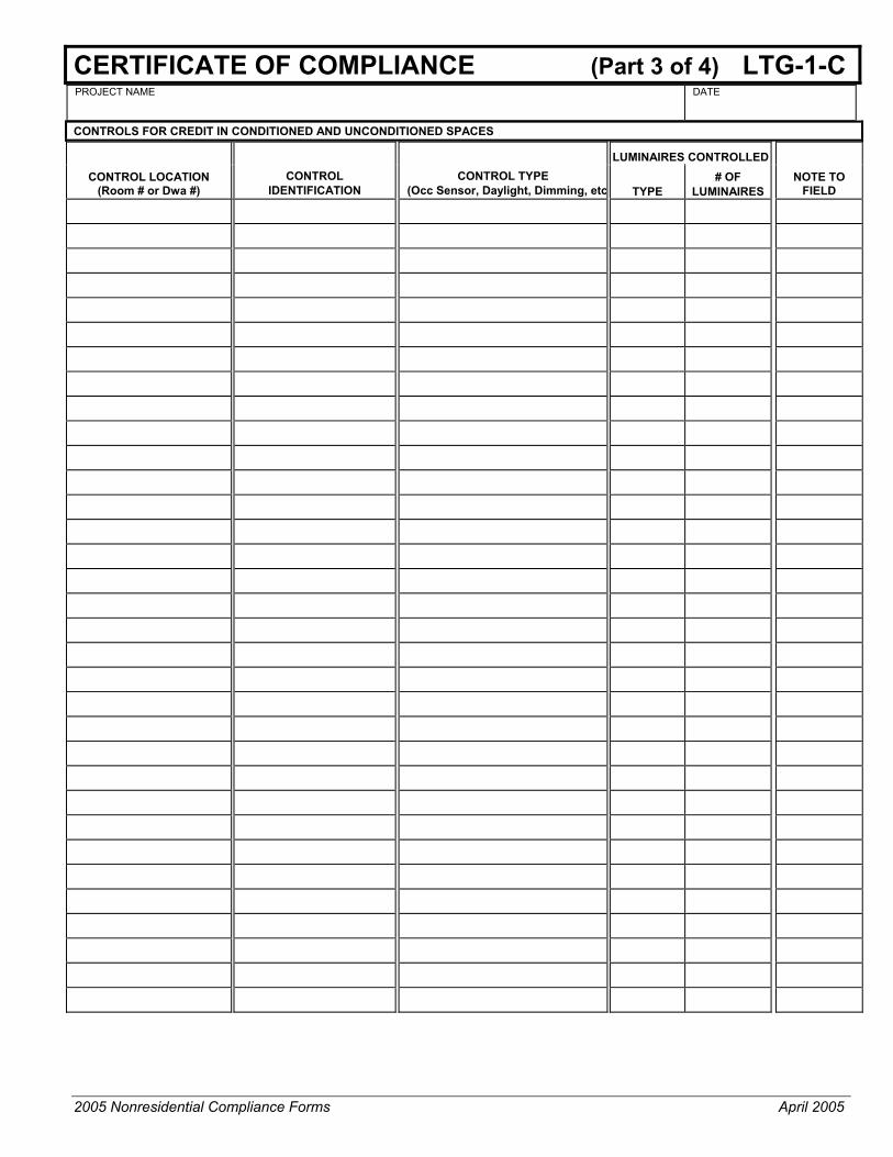
2005 Nonresidential Compliance Forms April 2005
CERTIFICATE OF COMPLIANCE (Part 3 of 4) LTG-1-C PROJECT NAME DATE
CONTROLS FOR CREDIT IN CONDITIONED AND UNCONDITIONED SPACES
LUMINAIRES CONTROLLEDCONTROL LOCATION
(Room # or Dwa #) CONTROL
IDENTIFICATION CONTROL TYPE
(Occ Sensor, Daylight, Dimming, etc TYPE # OF
LUMINAIRES NOTE TO
FIELD

2005 Nonresidential Compliance Forms April 2005
CERTIFICATE OF COMPLIANCE (Part 4 of 4) LTG-1-C PROJECT NAME DATE
Designer: This form is to be used by the designer and attached to the plans. Listed below are all the acceptance tests for lighting systems. The designer is required to check the boxes by all acceptance tests that apply and list all equipment that require an acceptance test. If all equipment of a certain type requires a test, list the equipment description and the number of systems to be tested in parentheses. The NJ number designates the Section in the Appendix of the Nonresidential ACM Manual that describes the test. Also indicate the person responsible for performing the tests (i.e. the installing contractor, design professional or an agent selected by the owner). Since this form will be part of the plans, completion of this section will allow the responsible party to budget for the scope of work appropriately.
Building Departments: Systems Acceptance. Before an occupancy permit is granted for a newly constructed building or space, or a new space-conditioning system serving a building or space is operated for normal use, all control devices serving the building or space shall be certified as meeting the Acceptance Requirements for Code Compliance. In addition a Certificate of Acceptance, MECH-1-A, Forms shall be submitted to the building department that:
A. Certifies plans, specifications, installation certificates, and operating and maintenance information meet the requirements of §10-103(b) and Title 24 Part 6.
Test Description Test Performed By:
LTG-2-A: Lighting Control Acceptance Document • Occupancy Sensor Acceptance • Manual Daylight Controls Acceptance • Automatic Time Switch Control Acceptance
Equipment requiring acceptance testing____________________________________
LTG-3-A: Automatic Daylighting Controls Acceptance Document
Equipment requiring acceptance testing _____________________________________

2005 Nonresidential Compliance Forms September 2005
INDOOR LIGHTING SCHEDULE (Part 1 of 2) LTG-2-C PROJECT NAME
DATE
INSTALLED LIGHTING POWER FOR CONDITIONED SPACES
Luminaire Lamps/Ballasts Installed Watts
A B C D E F G H I J
Name Type Description
Lamp
Type
Num
ber of Lam
ps per Lum
inaire
Watts
Per
Lamp
Num
ber of Ballast per Lum
inaire
Watts per
Luminaire
If C
EC
Default
Num
ber of Lum
inaires
Installed W
atts (G
x I )
PAGE TOTAL
BUILDING TOTAL (sum of all pages) + PORTABLE LIGHTING (From LTG-3-C) + CONTROL CREDIT (from LTG-4-C) -
ADJUSTED ACTUAL WATTS =

2005 Nonresidential Compliance Forms September 2005
INDOOR LIGHTING SCHEDULE (Part 2 of 2) LTG-2-C PROJECT NAME
DATE
INSTALLED LIGHTING POWER FOR UNCONDITIONED SPACES
Luminaire Lamps/Ballasts Installed Watts
A B C D E F G H I J
Name Type Description
Lamp
Type
Num
ber of Lam
ps per Lum
inaire
Watts P
er Lam
p
Num
ber of B
allast per Lum
inaire
Watts per
Luminaire If
CE
C
Default
Num
ber of Lum
inaires
Installed W
atts (G
x I)
BUILDING TOTAL (sum of all pages) +
CONTROL CREDIT (from LTG-4-C +
ADJUSTED ACTUAL WATTS +
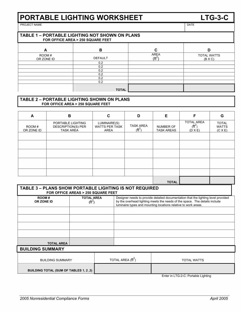
2005 Nonresidential Compliance Forms April 2005
PORTABLE LIGHTING WORKSHEET LTG-3-C PROJECT NAME DATE TABLE 1 – PORTABLE LIGHTING NOT SHOWN ON PLANS FOR OFFICE AREA > 250 SQUARE FEET
A
B
C
D
ROOM # OR ZONE ID
DEFAULT
AREA (ft2)
TOTAL WATTS (B X C)
0.2 0.2 0.2 0.2 0.2 0.2
TOTAL
TABLE 2 – PORTABLE LIGHTING SHOWN ON PLANS FOR OFFICE AREA > 250 SQUARE FEET
A B C D E F G
ROOM #
OR ZONE ID
PORTABLE LIGHTING DESCRIPTION(S) PER
TASK AREA
LUMINAIRE(S) WATTS PER TASK
AREA
TASK AREA
(ft2) NUMBER OF TASK AREAS
TOTAL AREA (ft2)
(D X E)
TOTAL WATTS (C X E)
TOTAL
TABLE 3 – PLANS SHOW PORTABLE LIGHTING IS NOT REQUIRED FOR OFFICE AREAS > 250 SQUARE FEET
ROOM # OR ZONE ID
TOTAL AREA (ft2)
Designer needs to provide detailed documentation that the lighting level provided by the overhead lighting meets the needs of the space. The details include luminaire types and mounting locations relative to work areas.
TOTAL AREA
BUILDING SUMMARY
BUILDING SUMMARY
TOTAL AREA (ft2) TOTAL WATTS
BUILDING TOTAL (SUM OF TABLES 1, 2 ,3)
Enter in LTG-2-C: Portable Lighting

2005 Nonresidential Compliance Forms September 2005
LIGHTING CONTROLS CREDIT WORKSHEET (Part 1 of 2) LTG-4-C CONTROL CREDITS FOR CONDITIONED SPACES
PROJECT NAME
DATE
A B C D E F G H I J DAYLIGHTING
ROOM #, ZONE ID
CONDITIONED AREAS
LIGHTING CONTROL
DESCRIPTION PLAN
REFEFERENCE
ROOM AREA (ft2)
WINDOWWALL RATIO
GLAZINGVLT
SKYLIGHT EFFECTIVEAPERTURE
1
WATTS OF CONTROL LIGHTING
LIGHTING ADJUSTMENT
FACTOR2
CONTROLCREDIT WATTS (H X I)
PAGE TOTAL 1) From Equation 146-A 2) From Table 146-A
BUILDING TOTAL
Enter in LTG-2-C: Lighting Control Credit

2005 Nonresidential Compliance Forms September 2005
LIGHTING CONTROLS CREDIT WORKSHEET (Part 2 of 2) LTG-4-C CONTROL CREDITS FOR UNCONDITIONED SPACES
PROJECT NAME
DATE
A B C D E F G H I J DAYLIGHTING LIGHTING
CONTROL
ROOM # ZONE ID
UNCONDITIONED AREAS DESCRIPTION
PLANS REFERENCE
ROOM AREA (ft2)
WINDOWWALL RATIO
GLAZINGVLT
SKYLIGHT EFFECT.
APERTURE1
WATTS OF CONTROL LIGHTING
LIGHTING ADJUSTMENT
FACTOR2
CONTROLCREDIT WATTS (H X I)
PAGE TOTAL 1) From Equation 146-A 2) From Table 146-A BUILDING TOTAL
Enter in LTG-2-C: Lighting Control Credit
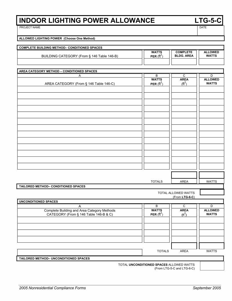
2005 Nonresidential Compliance Forms September 2005
INDOOR LIGHTING POWER ALLOWANCE LTG-5-C PROJECT NAME
DATE
ALLOWED LIGHTING POWER (Choose One Method)
COMPLETE BUILDING METHOD– CONDITIONED SPACES WATTS COMPLETE ALLOWED
BUILDING CATEGORY (From § 146 Table 146-B) PER (ft2) BLDG. AREA WATTS
AREA CATEGORY METHOD – CONDITIONED SPACES
A B C D WATTS AREA ALLOWED
AREA CATEGORY (From § 146 Table 146-C) PER (ft2) (ft2) WATTS
TOTALS AREA WATTS TAILORED METHOD– CONDITIONED SPACES
TOTAL ALLOWED WATTS
(From LTG-6-C) UNCONDITIONED SPACES
A B C D AREA ALLOWED Complete Building and Area Category Methods
CATEGORY (From § 146 Table 146-B & C) WATTS
PER (ft2) (ft2) WATTS
TOTALS AREA WATTS
TAILORED METHOD– UNCONDITIONED SPACES TOTAL UNCONDITIONED SPACES ALLOWED WATTS (From LTG-5-C and LTG-6-C)
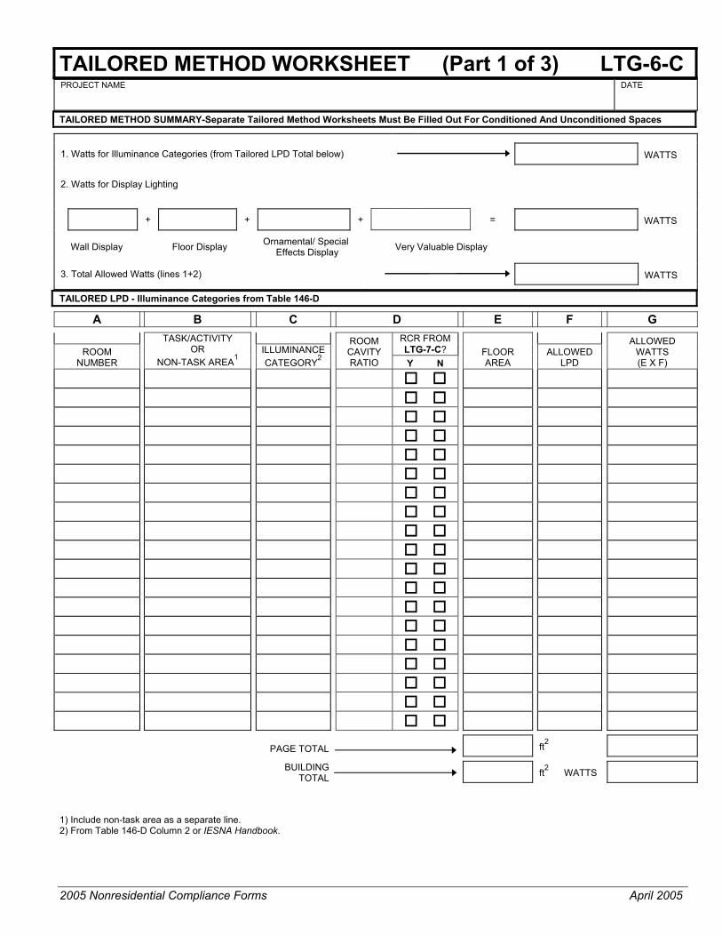
2005 Nonresidential Compliance Forms April 2005
TAILORED METHOD WORKSHEET (Part 1 of 3) LTG-6-C PROJECT NAME
DATE
TAILORED METHOD SUMMARY-Separate Tailored Method Worksheets Must Be Filled Out For Conditioned And Unconditioned Spaces
1. Watts for Illuminance Categories (from Tailored LPD Total below) WATTS
2. Watts for Display Lighting
+ + + = WATTS
Wall Display
Floor Display Ornamental/ Special Effects Display Very Valuable Display
3. Total Allowed Watts (lines 1+2) WATTS
TAILORED LPD - Illuminance Categories from Table 146-D
A B C D E F G
RCR FROM LTG-7-C? ROOM
NUMBER
TASK/ACTIVITY OR
NON-TASK AREA1 ILLUMINANCE CATEGORY2
ROOM CAVITY RATIO Y N
FLOOR AREA
ALLOWED LPD
ALLOWED WATTS (E X F)
PAGE TOTAL
ft2
BUILDING TOTAL
ft2 WATTS
1) Include non-task area as a separate line. 2) From Table 146-D Column 2 or IESNA Handbook.

2005 Nonresidential Compliance Forms April 2005
TAILORED METHOD WORKSHEET (Part 2 of 3) LTG-6-C PROJECT NAME
DATE
DISPLAY LIGHTING: WALLS
Qualifying wall display lighting systems shall be mounted within 6 ft to a wall, See §146(b)3B.
A B C D E F G H I J K ALLOTTED WATTS DESIGN WATTS
WALL
DISPLAY
WALL Display2,3 Power in ALLOTED DESIGN ALLOWED
Length in Watts per WATTS LUMIN. LUMIN WATTS/ WATTS WATTS TASK / ACTIVITY
MOUNTING HEIGHT
MOUNT HEIGHT
FACTOR1 Linear Feet Linear Feet (C X D X E) CODE QTY. LUMIN. (H X I) (Min. F or J)
TOTAL LENGTH OF DISPLAY WALLS ft2 TOTAL
Enter on Line 2, Part 1 of LTG-6-C WATTS 1) From Table 146-E. 2) From table 146-D Column 3. 3) Qualifying wall display lighting systems shall be mounted within 6 ft to a wall. DISPLAY LIGHTING: FLOORS
Qualifying floor display lighting systems shall be mounted no closer than 6 ft to a wall, See §146(b)3B.
A B C D E F G H I J K ALLOTTED WATTS DESIGN WATTS ALLOTTED
LIGHTING DESCRIPTION MOUNTING
HEIGHT
MOUNT HEIGHT
FACTOR4
FLOOR DISPLAY
AREA (ft2)
FLOOR DISPLAY
5,6 Power in
W/ft2
ALLOTED WATTS
(C X D X E)LUMIN.CODE
LUMIN QTY.
WATTS/LUMIN.
DESIGNWATTS(H X I)
ALLOWED WATTS
(Min. F or J)
TOTAL AREA FLOOR DISPLAYS
ft2
TOTAL WATTS
4) From table 146-E. 5) From table 146-D Column 4. 6) Qualifying floor display lighting systems shall be mounted no closer than 6 ft to a wall.

2005 Nonresidential Compliance Forms April 2005
TAILORED METHOD WORKSHEET (Part 3 of 3) LTG-6-C PROJECT NAME
DATE
DISPLAY LIGHTING: ORNAMENTAL/SPECIAL EFFECTS
A B C D E F G H I ALLOTTED WATTS DESIGN WATTS
LIGHTING DESCRIPTION
DISPLAY AREA (ft2)
Ornamental/ Special Effects
Lighting1
W/ft2
ALLOTTED WATTS (B XC)
LUMINAIRE CODE QUANTITY
WATTS/ LUMIN.
DESIGN WATTS (F X G)
ALLOWED WATTS
(Minimum of D or H)
TOTAL DISPLAY AREA ft2 TOTAL WATTS
1) See table 146-D Column 5. DISPLAY LIGHTING: VERY VALUABLE DISPLAY
A B C D E F G H I J K L ALLOTTED WATTS DESIGN WATTS
LUMINAIRE NAME OR LOCATION
VALUABLE DISPLAY
AREA (ft2)
VALUABLE DISPLAY POWER2
W/ft2
SPACE AREA
WATTS (B X C)
VALUABLEDISPLAY
AREA (ft2)
20 WATTS
PER (ft2)
DISPLAY AREA
WATTS (E X F)
LUMINAIRE CODE QUANTITY
WATTS / LUMINAIRE
DESIGN WATTS (I X J)
ALLOWED WATTS
(Minimum of D, G or K)
20 20 20 20 20 20 20 20
TOTAL AREA ft2 TOTAL AREA ft2 TOTAL WATTS
2) See table 146-D Column 6.

2005 Nonresidential Compliance Forms April 2005
ROOM CAVITY RATIO WORKSHEET (RCR ≥ 3.5) LTG-7-C PROJECT NAME
FOR ENFORCEMENT AGENCY USE ONLY
DOCUMENTATION AUTHOR DATE
PLAN CHECKED BY
DATE
RECTANGULAR SPACES
A B C D E F
Room
Number Task/Activity
Description
Room Length (L)
(ft)
Room Width (W)
(ft)
Room Cavity Height (H)
(ft)
Room Cavity Ratio
5 x H x (L+W) / (L x W)
NON-RECTANGULAR SPACES
A B C D E F
Room Number
Task/Activity Description
Room Area (A)
(ft2)
Room Perimeter (P)
(ft)
Room Cavity
Height (H) (ft)
Room Cavity Ratio
2.5 x H x P / A

2005 Nonresidential Compliance Forms September 2005
COMMON LIGHTING SYSTEMS METHOD LTG-8-C PROJECT NAME
DATE
The Common Lighting Systems method is only appropriate for Building Types listed in Table 146-B (Area Catagory Method Lighting Power Density Values) where the lighting power density is 1.0 Watts per square foot or greater.
CEC DEFAULT1? SPACE NAME
SPACE AREA
LUMINAIRE TYPE OR CODE
LUMINAIRE POWER Y N
LUMINAIRE SPACING OR LAYOUT
1) CEC default value from Nonresidential ACM Manual Appendix NB.

2005 Nonresidential Compliance Forms September 2005
LINE VOLTAGE TRACK LIGHTING WORKSHEET LTG-9-C PROJECT NAME
DATE
METHOD 1 – VOLT-AMPERE (VA) RATING OF THE BRANCH CIRCUIT(S) OR WATTAGE OF THE CURRENT LIMITERS - ONLY CURRENT LIMITERS CERTIFIED TO THE COMMISSION CAN BE WITH THIS METHOD
A B C D E F G Branch Circuit Option Current Limiter Option
BRANCH CIRCUIT NAME OR ID
VOLT-AMPERE (VA) RATING OF
THE BRANCH CIRCUIT
(Fill this column only if branch circuit
option is used for compliance)
TRACK EQUIPPED WITH CURRENT LIMITER (CL)?
(Columns C thru G may be left blank if the branch circuit option is used for
compliance)
IF YES
IF COLUMN (C) IS YES, LIST CURRENT LIMITER
WATTAGE (W)
TRACK LENGTH
(FT)
MULTIPLY TRACK LENGTH (E) BY 15 W/LF IF THERE IS CL, OR 45 W/LF IF THERE IS NO CL
(W)
TRACK WATTAGE – HIGHER OF
COLUMNS (D) OR (F)
(W)
SUB-TOTAL WATTS FOR TRACKS ON BRACH CIRCUIT – USE COLUMN (B) VA IF BRANCH CIRCUIT METHOD IS USED, OR TOTAL OF TRACK WATTS IN COLUMN (G) IF THE CL METHOD IS USED
SUB-TOTAL WATTS FOR TRACKS ON BRACH CIRCUIT – USE COLUMN (B) VA IF BRANCH CIRCUIT METHOD IS USED, OR TOTAL OF TRACK WATTS IN COLUMN (G) IF THE CL METHOD IS USED
SUB-TOTAL WATTS FOR TRACKS ON BRACH CIRCUIT – USE COLUMN (B) VA IF BRANCH CIRCUIT METHOD IS USED, OR TOTAL OF TRACK WATTS IN COLUMN (G) IF THE CL METHOD IS USED
TOTAL WATTS – ADD ALL SUBTOTALS
METHOD 2 – USE THE HIGHER OF: 45 WATTS / LINEAR FOOT OF TRACK – OR TOTAL RATED WATTAGE OF ALL OF ALL LUMINAIRES
A B C D E F
TRACK # OR NAME
LINEAR FEET OF TRACK (W/LF)
B x C (W)
TOTAL RATED WATTAGE OF ALL LUMINAIRES
LARGER OF (D or E)
45 45 45 45 45 45
TOTAL

2005 Nonresidential Compliance Forms April 2005
____________________________________________________ Outdoor Lighting Forms - Compliance
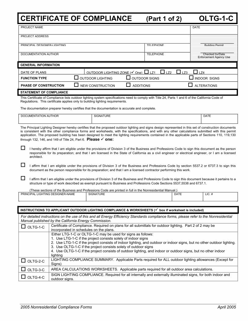
2005 Nonresidential Compliance Forms April 2005
CERTIFICATE OF COMPLIANCE (Part 1 of 2) OLTG-1-C PROJECT NAME DATE PROJECT ADDRESS
PRINCIPAL DESIGNER-LIGHTING TELEPHONE Building Permit
DOCUMENTATION AUTHOR TELEPHONE Checked by/Date Enforcement Agency Use
GENERAL INFORMATION
DATE OF PLANS
OUTDOOR LIGHTING ZONE ( One) LZ1 LZ2 LZ3 LZ4
FUNCTION TYPE OUTDOOR LIGHTING OUTDOOR SIGNS INDOOR SIGNS
PHASE OF CONSTRUCTION NEW CONSTRUCTION ADDITIONS ALTERATIONS
STATEMENT OF COMPLIANCE This Certificate of Compliance lists outdoor lighting system specifications need to comply with Title 24, Parts 1 and 6 of the California Code of Regulations. This certificate applies only to building lighting requirements. The documentation preparer hereby certifies that the documentation is accurate and complete. DOCUMENTATION AUTHOR
SIGNATURE
DATE
The Principal Lighting Designer hereby certifies that the proposed outdoor lighting and signs design represented in this set of construction documents is consistent with the other compliance forms and worksheets, with the specifications, and with any other calculations submitted with this permit application. The proposed building has been designed to meet the lighting requirements contained in the applicable parts of Sections 110, 119,130 through 132, 146, and 149 of Title 24, Part 6. Please one:
I hereby affirm that I am eligible under the provisions of Division 3 of the Business and Professions Code to sign this document as the person responsible for its preparation; and that I am licensed in the State of California as a civil engineer or electrical engineer, or I am a licensed architect.
I affirm that I am eligible under the provisions of Division 3 of the Business and Professions Code by section 5537.2 or 6737.3 to sign this document as the person responsible for its preparation; and that I am a licensed contractor performing this work.
I affirm that I am eligible under the provisions of Division 3 of the Business and Professions Code to sign this document because it pertains to a structure or type of work described as exempt pursuant to Business and Professions Code Sections 5537,5538 and 6737.1. (These sections of the Business and Professions Code are printed in full in the Nonresidential Manual.)
PRINCIPAL LIGHTING DESIGNER-NAME SIGNATURE DATE LIC. #
INSTRUCTIONS TO APPLICANT OUTDOOR LIGHTING COMPLIANCE & WORKSHEETS ( box if worksheet is included)
For detailed instructions on the use of this and all Energy Efficiency Standards compliance forms, please refer to the Nonresidential Manual published by the California Energy Commission.
OLTG-1-C Certificate of Compliance. Required on plans for all submittals for outdoor lighting. Part 2 of 2 may be incorporated in schedules on the plans.
Either LTG-1-C or OLTG-1-C may be used for signs as follows: 1. Use LTG-1-C if the project consists solely of indoor signs 2. Use LTG-1-C if the project consists of indoor lighting, and outdoor or indoor signs, but no other outdoor lighting. 3. Use OLTG-1-C if the project consists solely of outdoor signs 4. Use OLTG-1-C if the project consists of outdoor lighting, and indoor or outdoor signs, but no other indoor lighting
OLTG-2-C LIGHTING COMPLIANCE SUMMARY. Applicable Parts required for ALL outdoor lighting allowances (Except for Signs)
OLTG-3-C AREA CALCULATIONS WORKSHEETS. Applicable parts required for all outdoor area calculations.
OLTG-4-C SIGN LIGHTING COMPLIANCE. Required for all internally and externally illuminated signs, for both indoor and outdoor signs.

2005 Nonresidential Compliance Forms April 2005
CERTIFICATE OF COMPLIANCE (Part 2 of 2) OLTG-1-C PROJECT NAME
Lighting Schedules on Plans Show that Outdoor Lighting Meets Allowed Lighting Power Lighting power allowances for general site illumination on OLTG-2-C Part 1 of 4
Not Applicable
Lighting power allowances for local ordinances or for security multipliers on OLTG-2-C Part 2 of 4
Not Applicable
Lighting power allowances for specific applications, other than vehicle service stations with canopies on OLTG-2-C Part 3 of 4
Not Applicable
Lighting power allowances for vehicle service station canopies on OLTG-2-C Part 4 of 4
Not Applicable
Sign lighting compliance on OLTG-4-C
Not Applicable
Mandatory Measures on Plans Show that Outdoor Lighting Meets Outdoor Lighting Controls and Equipment Indicate location on plans of Note Block for Mandatory Measure
Installed lighting power has been determined in accordance with § 130(c)1
Not Applicable
All permanently installed luminaires with lamps rated over 100 watts either have a lamp efficacy of at least 60 lumens per watt or are controlled by a motion sensor § 132(a)
Not Applicable
All Luminaires with lamps rated greater than 175 watts in hardscape areas, including parking lots, building entrances, canopies, and all outdoor sales areas meet the Cutoff Requirements of § 132(b)
Not Applicable
All permanently installed outdoor lighting meets the Control Requirements of § 132(c)1
Not Applicable
Building facades, parking lots, garages, canopies, and outdoor sales areas meet the Multi-Level Lighting Requirements of § 132(c)2
Not Applicable
MANDATORY AUTOMATIC CONTROLS CONTROL LOCATION CONTROL
IDENTIFICATION CONTROL TYPE
Auto Time Switch/Photosensor, etcAREA CONTROLLED NOTE TO
FIELD

2005
Non
resi
dent
ial C
ompl
ianc
e Fo
rms
Apr
il 20
05
LIG
HTI
NG
CO
MPL
IAN
CE
SUM
MA
RY
(Par
t 1 o
f 4)
O
LTG
-2-C
PRO
JEC
T N
AME
D
ATE
LIG
HTI
NG
PO
WER
ALL
OW
AN
CES
– G
ENER
AL
SITE
ILLU
MIN
ATI
ON
– (T
able
147
-A)
A
llotte
d W
atts
Lu
min
aire
La
mps
/Bal
last
s In
stal
led
Wat
ts
A B
C
D
E
F G
H
I
J K
L
M
N
O
Li
ghtin
g Ap
plic
atio
ns
Cat
egor
y (T
able
147
-A)
Area (ft2) or Length (LF)
Allotted LPD W/ft2 or W/LF
Allotted Watts (B x C)
Code for Luminaire
Type
Des
crip
tion
Cutoff Designation
Lamp Type
Number of Lamps per
Luminaire
Watts per Lamp
Number of Ballast per
Luminaire
Watts per Luminaire
If CEC Default
Number of Luminaires
Installed Watts
( L x N )
Tota
l Allo
tted
Wat
ts
To
tal I
nsta
lled
Wat
ts

2005
Non
resi
dent
ial C
ompl
ianc
e Fo
rms
Apr
il 20
05
LIG
HTI
NG
CO
MPL
IAN
CE
SUM
MA
RY
(Par
t 2 o
f 4)
O
LTG
-2-C
PRO
JEC
T N
AME
D
ATE
LIG
HTI
NG
PO
WER
ALL
OW
AN
CES
– L
OC
AL
OR
DIN
AN
CE
(TA
BLE
147
-C) O
R S
ECU
RIT
Y M
ULT
IPLI
ERS
(TA
BLE
147
-D)
A
llotte
d W
atts
Lu
min
aire
La
mps
/Bal
last
s In
stal
led
Wat
ts
A
B
C
D
E F
G
H
I J
K
L M
N
O
P
Ligh
ting
appl
icat
ions
C
ateg
ory
Area (ft2) or Length (LF)
Allotted LPD W/ft2 or W/LF
SecurityMultiplier
If Applicable or “147-C”
Allotted Watts(B x C x D)
or (B x C)
Code for Luminaire
Type
Des
crip
tion
Cutoff Designation
Lamp Type
Number of Lamps per
Luminaire
Watts per Lamp
Numberof Ballast per
Luminaire
Watts per Luminaire
If CEC Default
Numberof Luminaires
Installed Watts
( M x O )
Che
cklis
t E
XCEP
TIO
N 1
TO
§ 1
47(c
)1 B
– T
here
is a
law
thro
ugh
a lo
cal o
rdin
ance
requ
iring
spe
cific
ligh
t lev
els,
and
ther
efor
e, t
he p
ower
allo
wan
ces
in T
able
147
-C w
ere
used
.

2005
Non
resi
dent
ial C
ompl
ianc
e Fo
rms
S
epte
mbe
r 200
5
LIG
HTI
NG
CO
MPL
IAN
CE
SUM
MA
RY
(P
art 3
of 4
)
OLT
G-2
-C
PRO
JEC
T N
AME
D
ATE
Ligh
ting
Pow
er A
llow
ance
for S
peci
fic A
pplic
atio
ns (T
AB
LE 1
47-B
) – O
ther
Tha
n Ve
hicl
e Se
rvic
e St
atio
n w
ithou
t Can
opie
s A
B
C
D
E
F G
H
I
J K
L
M
N
O
P Al
lotte
d W
atts
Lu
min
aire
Des
crip
tion
Lam
ps/B
alla
sts
D
esig
n W
atts
Ligh
ting
Appl
icat
ion
(Tab
le 1
47-B
)
Area (ft2) or Length (LF)
Allotted LPD W/ft2
or W/LF
Allotted Watts (B X C)
Code for Luminaire
Type
Des
crip
tion
Cutoff Designation
Lamp Type
Number of Lamps per
Luminaire
Watts per Lamp
Number of Ballast per
Luminaire
Watts per Luminaire
If CEC Default
Number of Luminaires
Design Watts ( L x N )
Allowed Watts Minimum of
( D or O)

2005
Non
resi
dent
ial C
ompl
ianc
e Fo
rms
Sep
tem
ber 2
005
LIG
HTI
NG
CO
MPL
IAN
CE
SUM
MA
RY
(P
art 4
of 4
)
OLT
G-2
-C
PRO
JEC
T N
AME
DAT
E
Ligh
ting
Pow
er A
llow
ance
for V
ehic
le S
ervi
ce S
tatio
n w
ithou
t Can
opie
s A
llotte
d W
atts
Lu
min
aire
La
mps
/ B
alla
sts
Des
ign
Wat
ts
A
B
C
D
E F
G
H
I J
K
L M
N
O
P
Number Single or
Double Sided Fuel
Dispensers
AreaSingle =
250 ft2 Double =
500 ft2
Allotted LPD W/ft2
Allotted Watts
(A x B x C)
Code for Luminaire
Type
Des
crip
tion
Cutoff Designation
Lamp Type
Number of Lamps per
Luminaire
Watts per Lamp
Number of Ballast per
Luminaire
Watts per Luminaire
If CEC Default
Number or
Luminaires
Design Watts ( L x N )
Allowed Watts
Minimum of ( D or O )

2005
Non
resi
dent
ial C
ompl
ianc
e Fo
rms
Apr
il 20
05
ILLU
MIN
ATE
D A
REA
CA
LCU
LATI
ON
WO
RK
SHEE
T (
Part
1 o
f 5)
O
LTG
-3-C
PR
OJE
CT
NAM
E
DAT
E
Har
dsca
pe -
Met
hod
( i )
A.
Har
dsca
pe fo
r aut
omot
ive
vehi
cula
r use
, inc
ludi
ng p
arki
ng lo
ts, d
rivew
ays
and
site
road
s A
B
C
D
E
F G
H
Are
as (f
t2 ) to
Sub
tract
from
with
in Il
lum
inat
ed A
rea
List
Spe
cific
App
licat
ion
(Tab
le 1
47-A
)
Act
ual P
aved
Are
a pl
us 5
’ pe
rimet
er o
f adj
acen
t un
pave
d la
nd.
Incl
udes
pl
ante
rs a
nd la
ndsc
aped
ar
eas
less
than
10’
wid
e th
at a
re e
nclo
sed
by
hard
scap
e on
at l
east
3
side
s
Are
as b
etw
een
pole
s or
lu
min
aire
s th
at
are
grea
ter t
han
6 m
ount
ing
heig
ht d
ista
nce
(If A
pplic
able
)
Ove
rlapp
ing
Are
as o
f A
noth
er
Appl
icat
ion
or
Lum
inai
re
Build
ing
Area
s
Are
as
Obs
truct
ed
By
Sig
n or
O
ther
S
truct
ure
Sub
Tota
l of
are
as to
S
ubtra
ct
(C +
D +
E
+ F
) Ill
umin
ated
Are
a (B
– G
)
B.
Har
dsca
pe fo
r ped
estr
ian
use,
incl
udin
g pl
azas
, sid
ewal
ks, w
alkw
ays
and
bike
way
s A
B
C
D
E
F G
H
A
reas
(ft2 ) t
o S
ubtra
ct fr
om w
ithin
Illu
min
ated
Are
a
List
Spe
cific
App
licat
ion
(Tab
le 1
47-A
)
Act
ual P
aved
Are
a pl
us 5
’ of
unp
aved
land
on
eith
er
side
of p
ath
of tr
avel
. S
hall
incl
ude
all c
ontig
uous
pa
ved
area
bef
ore
incl
udin
g ad
jace
nt g
roun
ds.
Are
as b
etw
een
pole
s or
lu
min
aire
s th
at
are
grea
ter t
han
6 m
ount
ing
heig
ht d
ista
nce
(If
App
licab
le)
Ove
rlapp
ing
Are
as o
f A
noth
er
Appl
icat
ion
or
Lum
inai
re
Build
ing
Are
as
Are
as
Obs
truct
ed
By
Sig
n or
O
ther
S
truct
ure
Sub
Tota
l of
are
as to
S
ubtra
ct
(C +
D +
E
+ F
)
Illum
inat
ed A
rea
(B
– G
)
Che
cklis
t §
147
(c)1
B –
Eac
h po
rtion
of a
ll illu
min
ated
are
as h
as b
een
assi
gned
onl
y on
e lig
htin
g ap
plic
atio
n, a
nd th
e ap
plic
atio
ns a
re c
onsi
sten
t with
the
actu
al u
se o
f the
are
as.
§ 1
47(c
)1 A
- G
ener
al il
lum
inat
ion
area
s in
clud
es o
nly
thos
e illu
min
ated
are
as th
at a
re in
the
boun
ds o
f the
App
licat
ion
and
are
with
in a
squ
are
patte
rn a
roun
d a
lum
inai
re th
at
is s
ix ti
mes
the
lum
inai
re m
ount
ing
heig
ht, w
ith th
e lu
min
aire
in th
e m
iddl
e of
the
patte
rn, l
ess
any
area
s th
at a
re w
ithin
bui
ldin
gs, u
nder
can
opie
s, b
eyon
d pr
oper
ty li
nes,
or
obst
ruct
ed b
y a
sign
s or
oth
er s
truct
ures
.

2005
Non
resi
dent
ial C
ompl
ianc
e Fo
rms
Jul
y 20
05
ILLU
MIN
ATE
D A
REA
CA
LCU
LATI
ON
WO
RK
SHEE
T
(Par
t 2 o
f 5)
O
LTG
-3-C
PR
OJE
CT
NAM
E
DAT
E
A.
Har
dsca
pe M
etho
d ii
Har
dsca
pe fo
r driv
eway
s, s
ite ro
ads,
sid
ewal
ks, w
alkw
ays
and
bike
way
s -
A
B
List
Spe
cific
App
licat
ion
(Tab
le 1
47-A
) Le
ngth
of 2
5’ w
ide
path
inco
rpor
atin
g as
m
uch
of th
e pa
ved
area
as
poss
ible
.
Che
cklis
t §
147
(c)1
B –
Eac
h po
rtion
of a
ll illu
min
ated
are
as h
as b
een
assi
gned
onl
y on
e lig
htin
g ap
plic
atio
n, a
nd th
e ap
plic
atio
ns a
re c
onsi
sten
t with
the
actu
al u
se o
f the
are
as.
§ 1
47(c
)1 B
Met
hod
ii –
Gen
eral
illu
min
atio
n ar
eas
for s
ite ro
adw
ay, d
rivew
ay, s
idew
alk,
wal
kway
, or b
ikew
ay in
clud
es o
nly
thos
e illu
min
ated
are
as th
at a
re in
the
boun
ds o
f the
Ap
plic
atio
n an
d in
clud
es a
25
foot
wid
e ar
ea ru
nnin
g al
ong
the
axis
of t
he p
ath
of tr
avel
and
incl
udes
as
muc
h of
the
pave
d ar
ea a
s po
ssib
le
B.
Bui
ldin
g En
tran
ces
with
out C
anop
ies
A B
C
Wid
th o
f Doo
r plu
s 3
feet
S
mal
ler o
f 18
feet
or d
ista
nce
to th
e ed
ge o
f the
pr
oper
ty li
ne
Area
(A
x B
) (ft2 )
Che
cklis
t §
147
(c)1
B –
Eac
h po
rtion
of a
ll illu
min
ated
are
as h
as b
een
assi
gned
onl
y on
e lig
htin
g ap
plic
atio
n, a
nd th
e ap
plic
atio
ns a
re c
onsi
sten
t with
the
actu
al u
se o
f the
are
as.
§ 1
47(c
)1 A
- G
ener
al il
lum
inat
ion
area
s in
clud
es o
nly
thos
e illu
min
ated
are
as th
at a
re in
the
boun
ds o
f the
App
licat
ion
and
are
with
in a
squ
are
patte
rn a
roun
d a
lum
inai
re th
at
is s
ix ti
mes
the
lum
inai
re m
ount
ing
heig
ht, w
ith th
e lu
min
aire
in th
e m
iddl
e of
the
patte
rn, l
ess
any
area
s th
at a
re w
ithin
bui
ldin
gs, u
nder
can
opie
s, b
eyon
d pr
oper
ty li
nes,
or
obst
ruct
ed b
y a
sign
s or
oth
er s
truct
ures
.

2005
Non
resi
dent
ial C
ompl
ianc
e Fo
rms
Apr
il 20
05
ILLU
MIN
ATE
D A
REA
CA
LCU
LATI
ON
WO
RK
SHEE
T
(Par
t 3 o
f 5)
O
LTG
-3-C
PR
OJE
CT
NAM
E
DAT
E
A.
Out
door
Sal
es L
ot F
ront
age
and
Sale
s Lo
t Are
a A
B
C
D
E
F G
H
If
an O
utdo
or S
ales
Fro
ntag
e al
lotm
ent w
as u
sed,
sub
tract
that
are
a fro
m th
e G
ross
Illu
min
ated
Are
a
Gro
ss Il
lum
inat
ed A
rea
(ft2 )
Mou
ntin
g he
ight
of
Sal
es
Fron
tage
Lu
min
aire
s (fe
et)
3
X B
Dis
tanc
e (In
pla
n vi
ew)
from
fron
tage
lu
min
aire
to fr
ont
edge
of S
ales
Lot
Sale
s Lo
t Fr
onta
ge
Leng
th (f
eet)
Sale
s Fr
onta
ge
Area
(C
– D
) x E
(ft
2 )
Ove
rlap-
ping
Are
as
of A
noth
er
Appl
icat
ion
Sale
s Lo
t Are
a A
- F
- G
Che
cklis
t §
147
(c)1
B –
Eac
h po
rtion
of a
ll illu
min
ated
are
as h
as b
een
assi
gned
onl
y on
e lig
htin
g ap
plic
atio
n, a
nd th
e ap
plic
atio
ns a
re c
onsi
sten
t with
the
actu
al u
se o
f the
are
as.
§ 1
47(c
) 2 B
- M
easu
red
in p
lan
view
, onl
y illu
min
ated
sec
tions
of o
utdo
or s
ales
fron
tage
are
as th
at a
re im
med
iate
ly a
djac
ent t
o th
e pr
inci
pal v
iew
ing
loca
tion
and
unob
stru
cted
vi
ewin
g le
ngth
, and
are
with
in a
3 m
ount
ing
heig
hts
of th
e fro
ntag
e ha
ve b
een
used
. Lu
min
aire
s qu
alify
ing
for t
his
allo
wan
ce a
re lo
cate
d in
pla
n vi
ew b
etw
een
the
prin
cipa
l vie
win
g lo
catio
n an
d th
e fro
ntag
e ou
tdoo
r sal
es.
B.
Bui
ldin
g Fa
çade
Are
a A
B
C
D
E
F G
H
A
reas
(ft2 ) t
o S
ubtra
ct fr
om th
e G
ross
Illu
min
ated
Are
a D
o no
t dou
ble
coun
t any
are
as
Des
igna
ted
Nam
e an
d O
rient
atio
n Le
ngth
H
eigh
t G
ross
Are
a (B
x C
)
Are
as
cove
red
by
sign
s
Are
a fo
r whi
ch
Illum
inat
ion
is
Obs
truct
ed b
y O
ther
O
bjec
ts a
nd
Are
a N
ot Il
lum
inat
ed
Sub
Tota
l (E
+F)
Net
Are
a A
vaila
ble
for
Faça
de L
ight
ing
(D-G
)
Che
cklis
t §
147
(c)1
B –
Eac
h po
rtion
of a
ll illu
min
ated
are
as h
as b
een
assi
gned
onl
y on
e lig
htin
g ap
plic
atio
n, a
nd th
e ap
plic
atio
ns a
re c
onsi
sten
t with
the
actu
al u
se o
f the
are
as.
§ 1
47(c
) 2 A
– O
nly
faca
des
area
s th
at a
re il
lum
inat
ed w
ithou
t obs
truct
ion
or in
terfe
renc
e, b
y on
e or
mor
e lu
min
aire
s, h
ave
been
use
d.

2005
Non
resi
dent
ial C
ompl
ianc
e Fo
rms
Apr
il 20
05
ILLU
MIN
ATE
D A
REA
CA
LCU
LATI
ON
WO
RK
SHEE
T
(Par
t 4 o
f 5)
O
LTG
-3-C
PR
OJE
CT
NAM
E
DAT
E
Orn
amen
tal L
ight
ing,
Can
opie
s, V
ehic
le S
ervi
ce S
tatio
n H
ards
cape
, and
Out
door
Din
ing
A
B
C
D
E F
G
Are
as (f
t2 ) to
Sub
tract
from
with
in Il
lum
inat
ed A
rea
Ligh
ting
Appl
icat
ion
(Tab
le 1
47-B
)
G
ross
Illu
min
ated
A
rea
of A
pplic
atio
n (ft
2 )
Are
as b
etw
een
pole
s or
lu
min
aire
s th
at a
re
grea
ter t
han
6 m
ount
ing
heig
ht d
ista
nce
(If A
pplic
able
)
Ove
rlapp
ing
Are
as o
f A
noth
er
Appl
icat
ion
or
Lum
inai
re
Are
as
Obs
truct
ed
By
Sig
n or
O
ther
S
truct
ure
Sub
Tota
l of
are
as to
S
ubtra
ct
(C +
D +
E)
Illum
inat
ed A
rea
(B –
F)
Che
cklis
t §
147
(c)1
B –
Eac
h po
rtion
of a
ll illu
min
ated
are
as h
as b
een
assi
gned
onl
y on
e lig
htin
g ap
plic
atio
n, a
nd th
e ap
plic
atio
ns a
re c
onsi
sten
t with
the
actu
al u
se o
f the
are
as.
§ 1
47(c
) 2 C
- Th
e ar
ea o
f orn
amen
tal l
ight
ing
incl
udes
no
mor
e th
an th
e to
tal a
rea
of th
e si
te e
xter
nal t
o bu
ildin
gs.
Lum
inai
res
used
for o
rnam
enta
l lig
htin
g em
ploy
lam
ps ra
ted
100
wat
ts o
r les
s, a
nd a
re n
ot u
sed
to d
eter
min
e LP
D fo
r gen
eral
illu
min
atio
n.
§ 1
47(c
) 2 D
– M
easu
red
in p
lan
view
, the
are
as o
f illu
min
ated
can
opie
s in
clud
e th
e ho
rizon
tal p
roje
ctio
n of
the
cano
pies
. §
147
(c) 2
F –
The
are
a of
veh
icle
ser
vice
sta
tion
hard
scap
e in
clud
es o
nly
illum
inat
ed h
ards
cape
are
as b
eyon
d th
e ho
rizon
tal p
roje
ctio
n of
the
cano
py in
pla
n vi
ew.
§ 1
47(c
) 2 I
– Th
e ar
ea o
f out
door
din
ing
area
incl
udes
onl
y illu
min
ated
har
dsca
pe a
reas
use
d to
ser
ve a
nd c
onsu
me
food
and
bev
erag
es.

2005
Non
resi
dent
ial C
ompl
ianc
e Fo
rms
S
epte
mbe
r 200
5
ILLU
MIN
ATE
D A
REA
CA
LCU
LATI
ON
WO
RK
SHEE
T
(Par
t 5 o
f 5)
O
LTG
-3-C
PR
OJE
CT
NAM
E
DAT
E
A.
Driv
e U
p W
indo
ws A
B
C
Wid
th o
f Win
dow
plu
s 6
feet
(LF)
S
mal
ler o
f 30
feet
or d
ista
nce
to th
e ed
ge o
f the
pro
perty
line
(LF)
Ar
ea
(A x
B) (
ft2 )
Che
cklis
t
Ent
er e
ach
Are
a in
OLT
G-2
-C (P
art 3
of 4
) in
Col
umn
B
to c
alcu
late
allo
tted
wat
ts.
§ 1
47(c
) 1 B
– E
ach
porti
on o
f all
illum
inat
ed a
reas
has
bee
n as
sign
ed o
nly
one
light
ing
appl
icat
ion,
and
the
appl
icat
ions
are
con
sist
ent w
ith th
e ac
tual
use
of t
he a
reas
. §
147
(c) 2
G –
Driv
e up
win
dow
are
a in
clud
es o
nly
illum
inat
ed a
rea
that
is th
e pr
oduc
t of t
he w
idth
of t
he w
indo
w p
lus
six
feet
, and
a d
ista
nce
of u
p to
30
feet
out
war
d fro
m th
e w
indo
w (n
ot g
oing
bey
ond
prop
erty
line
s).
B.
Gua
rded
Fac
ility
A
B
C
D
Are
a of
Gua
rdho
use
Indo
or (f
t2 ) S
mal
ler o
f 80
feet
or d
ista
nce
to th
e ed
ge o
f the
pro
perty
line
(LF)
E
ntra
nce
Are
a (B
x 2
5ft)
(ft2 )
Are
a (A
+ C
) (ft
2 )
Che
cklis
t
E
nter
eac
h A
rea
in O
LTG
-2-C
(Par
t 3 o
f 4)
in C
olum
n B
to c
alcu
late
allo
tted
wat
ts.
§ 1
47(c
) 1 B
– E
ach
porti
on o
f all
illum
inat
ed a
reas
has
bee
n as
sign
ed o
nly
one
light
ing
appl
icat
ion,
and
the
appl
icat
ions
are
con
sist
ent w
ith th
e ac
tual
use
of t
he a
reas
. §
147
(c) 2
H –
The
are
a of
gua
rded
faci
litie
s in
clud
es il
lum
inat
ed a
reas
that
incl
ude
the
guar
dhou
se in
door
are
a pl
us th
e pr
oduc
t of t
he e
ntra
nce
wid
th o
f 25
feet
and
leng
th o
f up
to 8
0 fe
et (n
ot g
oing
bey
ond
the
prop
erty
line
).

2005
Non
resi
dent
ial C
ompl
ianc
e Fo
rms
Apr
il 20
05
SIG
N L
IGH
TIN
G C
OM
PLIA
NC
E
O
LTG
-4-C
PR
OJE
CT
NAM
E
D
ATE
Al
tern
ativ
e 1
– Li
ghtin
g Po
wer
Allo
wan
ces
Alte
rnat
ive
2 –
For S
igns
that
ON
LY u
se o
ne o
r mor
e of
the
tech
nolo
gies
list
ed in
M th
roug
h S
(Che
ck a
ll th
at a
pply
) A
B
C
D
E
F1 G
H
I
J K
L
M
N
O
P Q
R
S
Allo
tted
Wat
ts
Lam
p / B
alla
st
Des
ign
Wat
ts
Sign Symbol or Code
Quantity of Signs
Des
crip
tion
or
Loca
tion
Sign Area (ft2)
Internally (I) OR Externally (E)
Illuminated
Allotted LPD (12 or 2.3)
(W / ft2)
Allotted Watts (D X F)
Lamp Type
Number of OR Lineal Feet of Lamps
Number of Ballasts In Signs
Total Designed Sign Input watts
Is G Smaller than K? Y / N
High Pressure Sodium
Pulse Start or Ceramic Metal Halide
Neon and Cold Cathode
Light Emitting Diode (LED)
Barrier Coat Fluorescent Lamps (includes most T5
and T8 lamps)
CFLs not containing Medium Screw Base
Sockets
Electronic Ballasts with Output Frequency of
20kHz or more
F1 For
Allo
tted
LPD
use
12
wat
ts/s
quar
e fo
ot fo
r Int
erna
lly Il
lum
inat
ed S
igns
, and
use
2.3
wat
ts/ft
2 fo
r Ext
erna
lly Il
lum
inat
ed S
igns
.
Not
e: I
f an
Inte
rnal
ly Il
lum
inat
ed o
r Ext
erna
lly Il
lum
inat
ed s
ign
cont
ains
ligh
t sou
rces
and
bal
last
s ot
her t
han
thos
e in
clud
ed in
col
umns
(M) t
hrou
gh (S
), su
ch
as in
cand
esce
nt la
mps
, med
ium
bas
e so
cket
s, m
agne
tic b
alla
sts,
etc
, the
n th
e si
gn m
ust c
ompl
y un
der A
ltern
ativ
e 1.
H
owev
er, u
nfilt
ered
sig
ns, a
nd
unfil
tere
d po
rtion
s of
Inte
rnal
ly a
nd E
xter
nally
illu
min
ated
sig
ns, a
re n
ot re
quire
d to
mee
t the
se S
tand
ards
.

2005 Nonresidential Compliance Forms June 2005
______________________________________________________ Lighting Forms - Acceptance

2005 CERTIFICATE OF ACCEPTANCE (Part 1 of 2) LTG-1-APROJECT NAME DATE
PROJECT ADDRESS
TESTING AUTHORITY TELEPHONE
GENERAL INFORMATIONDATE OF BLDG. PERMIT PERMIT # BLDG. CONDITIONED FLOOR AREA CLIMATE ZONE
BUILDING TYPE □ NONRESIDENTIAL □ HIGH RISE RESIDENTIAL □ HOTEL/MOTEL GUEST ROOM
PHASE OF CONSTRUCTION □ NEW CONSTRUCTION □ ADDITION □ ALTERATION □ UNCONDITIONED
STATEMENT OF ACCEPTANCE
TESTING AUTHORITY - NAME SIGNATURE DATE LIC.#
INSTRUCTIONS TO APPLICANT
Part 1 of 2 - Statement of AcceptancePart 2 of 2 - Summary of Acceptance Tests
(These sections of the Business and Professions Code are printed in full in the Nonresidential Manual.)
For Detailed instructions on the use of this and all Energy efficiency Standards acceptance forms, please refer to the Nonresidential Manual published by the California Energy Commission.
I affirm that I am eligible under the exemption to Division 3 of the Business and Professions Code by Section 5537.2 or 6737.3 to sign this document as the person responsible for its preparation; and that I am a licensed contractor performing this work.
□
I affirm that I am eligible under the exemption to Division 3 of the business and Professions Code to sign this document because it pertains to a structure or type of work described pursuant to Business and Professions Code sections 5537, 5538, and 6737.1.
□
__________________________ Checked by/Date
Enforcement Agency Use
This Certificate of Acceptance summarizes the results of the acceptance tests related to building lighting requirements per Title 24, Part 6. (Sections 119(d), 119(e), 131(d))
I hereby affirm that I am eligible under the provisions of Division 3 of the Business and Professions Code to sign this document as the person responsible for it's preparation; and that I am licensed in the State of California as a civil engineer or electrical engineer, or I am a licensed architect.
□Please check one:
2005 Nonresidential Acceptance Forms June 2005

2005 CERTIFICATE OF ACCEPTANCE (Part 2 of 2) LTG-1-APROJECT NAME DATE
SUMMARY OF ACCEPTANCE TESTSTESTING AUTHORITY DATE OF TEST PASS / FAIL NOTES Bldg.
Dept. Use
NOTE: Use additional sheets as necessary
SYSTEM ACCEPTANCE DOCUMENT Form____of ____)
2005 Nonresidential Acceptance Forms April 2005
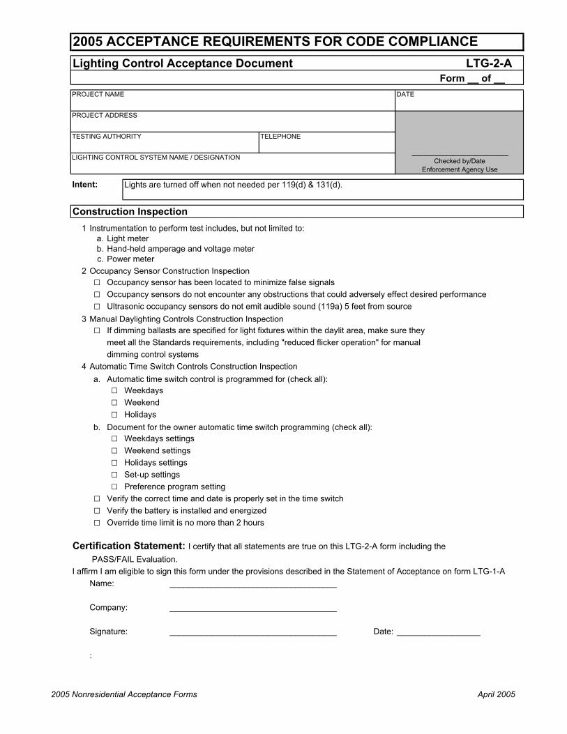
Lighting Control Acceptance Document LTG-2-AForm __ of __
PROJECT NAME DATE
PROJECT ADDRESS
TESTING AUTHORITY TELEPHONE
LIGHTING CONTROL SYSTEM NAME / DESIGNATION
Construction Inspection1 Instrumentation to perform test includes, but not limited to:
a. Light meterb. Hand-held amperage and voltage meterc. Power meter
2 Occupancy Sensor Construction Inspection□ Occupancy sensor has been located to minimize false signals□ Occupancy sensors do not encounter any obstructions that could adversely effect desired performance□ Ultrasonic occupancy sensors do not emit audible sound (119a) 5 feet from source
3 Manual Daylighting Controls Construction Inspection□ If dimming ballasts are specified for light fixtures within the daylit area, make sure they
meet all the Standards requirements, including "reduced flicker operation" for manualdimming control systems
4 Automatic Time Switch Controls Construction Inspectiona. Automatic time switch control is programmed for (check all):
□ Weekdays□ Weekend□ Holidays
b. Document for the owner automatic time switch programming (check all):□ Weekdays settings□ Weekend settings□ Holidays settings□ Set-up settings□ Preference program setting
□ Verify the correct time and date is properly set in the time switch□ Verify the battery is installed and energized□ Override time limit is no more than 2 hours
Certification Statement: I certify that all statements are true on this LTG-2-A form including the PASS/FAIL Evaluation.
I affirm I am eligible to sign this form under the provisions described in the Statement of Acceptance on form LTG-1-AName:
Company:
Signature: Date:
:
2005 ACCEPTANCE REQUIREMENTS FOR CODE COMPLIANCE
__________________________ Checked by/Date
Enforcement Agency Use
Intent: Lights are turned off when not needed per 119(d) & 131(d).
____________________________________
____________________________________
____________________________________ __________________
2005 Nonresidential Acceptance Forms April 2005

Lighting Control Acceptance Document LTG-2-AForm __ of __
PROJECT NAME DATE
2005 ACCEPTANCE REQUIREMENTS FOR CODE COMPLIANCE
A. Select Acceptance Test (Indicate lighting control systems Names/Designations by the applicable tests below)□ 1 Occupancy Sensor□ 2 Manual Daylighting Controls□ 3 Automatic Time Switch Controls
B. Equipment Testing RequirementsCheck and verify those items applicable to selected system: 1 2 3Occupancy Sensor - Step 1: Simulate an unoccupied condition
Y / N
Y / N
c. Signal sensitivity is adequate to achieve desired control Y / NStep 2: Simulate an occupied condition
a. Status indicator or annunciator operates correctly Y / NY / N
c. Sensor indicates space is "occupied" and lights turn on manually Y / NStep 3: System returned to initial operating conditions Y / NManual Daylighting Controls - Step 1: Manual switching control
a.Y / N
b. The amount of light delivered to the space is uniformly reduced Y / NStep 2: System returned to initial operating conditions Y / NAutomatic Time Switch Controls - Step 1: Simulate occupied condition
a. All lights can be turned on and off by their respective area control switch Y / NY / N
Step 2: Simulate unoccupied conditiona. All non-exempt lighting turn off per Section 131(d)1 Y / N
Y / N
c. All non-exempt lighting turns off Y / NStep 3: System returned to initial operating conditions Y / NNote: Shaded areas do not apply for particular test procedure
C. PASS / FAIL Evaluation (check one):□
□
PASS: All applicable Construction Inspection responses are complete and all applicable Equipment Testing Requirements responses are positive (Y - yes)FAIL: Any applicable Construction Inspection responses are incomplete OR there is one or more negative (N - no) responses in any applicable Equipment Testing Requirements section. Provide explanation below. Use and attach additional pages if necessary.
Verify the switch only operates lighting in the ceiling-height partitioned area in which the switch is located
Manual override switch allows only the lights in the selected ceiling height partitioned space where the override switch is located, to turn on or remain on until the next scheduled shut off occurs
Lights controlled by occupancy sensors turn off within a maximum of 30 minutes from start of an unoccupied condition per Standard Section 119(d)
The occupant sensor does not trigger a false "on" from movement in an area adjacent to the controlled space or from HVAC operation
Lights controlled by occupancy sensors turn on when Immediately upon an occupied condition OR (this requirement is mutually exclusive with Step 2.c.)
At least 50% of lighting power in daylit areas is separately controlled from other lights
Applicable Lighting Control Systems
b.
b.
a.
b.
b.
2005 Nonresidential Acceptance Forms April 2005

Automatic Daylighting Controls Acceptance Document LTG-3-AForm __ of __
PROJECT NAME DATE
PROJECT ADDRESS
TESTING AUTHORITY TELEPHONE
AUTOMATIC DAYLIGHTING CONTROL NAME / DESIGNATION
Construction Inspection
1 Instrumentation to perform test includes, but not limited to:a. Light meterb. Hand-held amperage and voltage meterc. Power meter
2 Documentation of all control devices (photocells) have been properly located including:a. Factory-calibrated (proof required)
□ Factory-calibration certificate attachedb. Field-calibrated
□ Setpoint properly set□ Lighting threshold
3 Documentation has been provided by the installer for:□ Setpoints for each device□ Settings for each device□ Programming for each device
4 Luminaires controlled by automatic daylighting controls are only in daylit areas; and□ Separately circuited for daylit areas by windows and daylit areas under skylights
Certification Statement: I certify that all statements are true on this LTG-3-A form including the PASS/FAIL Evaluation.
I affirm I am eligible to sign this form under the provisions described in the Statement of Acceptance on form LTG-1-AName:
Company:
Signature: Date:
:
__________________
2005 ACCEPTANCE REQUIREMENTS FOR CODE COMPLIANCE
__________________________ Checked by/Date
Enforcement Agency Use
Intent: Verify operation of daylighting systems meet 119(e)2.
____________________________________
____________________________________
____________________________________
2005 Nonresidential Acceptance Forms April 2005

Automatic Daylighting Controls Acceptance Document LTG-3-AForm __ of __
PROJECT NAME DATE
2005 ACCEPTANCE REQUIREMENTS FOR CODE COMPLIANCE
A. Control System (check all applicable systems and list lighting control systems Names/Designations)□ 1 Continuous Dimming Control Systems□ 2 Stepped Dimming Control Systems□ 3 Stepped Switching Control Systems
B. Equipment Testing Requirements Applicable Control SystemCheck and verify those applicable to specific simulation mode: 1 2 3Step 1: Simulate bright conditionsa. Measured lighting power at fully dimmed condition kW =b. Rated lighting power at full light output kW =c. Y / N
d. Only luminaries in daylit zone are affected by daylight control Y / N Y / N Y / Ne. Y / N
f. Y / N
g. Y / N Y / N Y / N
h. Y / N
I. Y / N Y / N
j. Y / N Y / N
k. Minimum time delay between step changes is 3 minutes to prevent short cycling Y / Nl. Y / N
m. Y / N
Step 2: Simulate dark conditionsa. Y / N Y / N
b. Y / N Y / N Y / N
c. Y / N Y / N Y / N
d. Minimum time delay between step changes is 3 minutes to prevent short cycling Y / Ne. Y / N
Step 3: System returned to initial operating conditions Y / N Y / N Y / N
C. PASS / FAIL Evaluation (check one):□
□ FAIL: Any applicable Construction Inspection responses are incomplete OR there is one or more negative (N - no) responses in any applicable Equipment Testing Requirements section. Attach additional pages with explanation.
Lumen measurements in the space, location of measurements and specific device settings, program setting and other measurements are documented
Lighting power reduced by at least 50% in daylit area by windows and at least 65% in daylit areas under skylights.
Automatic daylight control system increases the amount of light delivered to the space uniformly
PASS: All applicable Construction Inspection responses are complete and all applicable Equipment Testing Requirements responses are positive (Y - yes)
Single- or multiple-stepped switching controls provide a dead band of at least three minutes between switching threshold to prevent short cycling
Dimming control system provides reduced flicker operation over the entire operating range per Standards Section 119(e)2.Lumen measurements in the space, location of measurements and specific device settings, program setting and other measurements are documented
Automatic daylight control system reduces the amount of light delivered to the space per manufacturer's specifications for power level versus light level
Lighting power reduction is at least 50% under fully switched conditions per Standards Section 119(e)1Single- or multiple-stepped switching controls provide a dead band of at least three minutes between switching threshold to prevent short cycling
Automatic daylight control system reduces the amount of light delivered to the space uniformly
Dimming control system provides reduced flicker operation over the entire operating range per Standards Section 119(e)2.
Lighting power reduced by at least 50% in daylit area by windows and at least 65% in daylit areas under skylights.
Automatic daylight control system reduces the amount of light delivered to the space relatively uniformly as per Section 131(b)
2005 Nonresidential Acceptance Forms April 2005

2005 Nonresidential Compliance Forms June 2005
______________________________________________________ Mechanical Forms - Acceptance
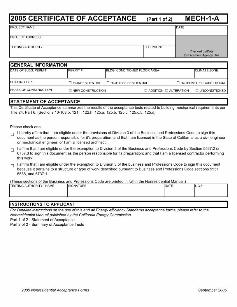
2005 CERTIFICATE OF ACCEPTANCE (Part 1 of 2) MECH-1-APROJECT NAME DATE
PROJECT ADDRESS
TESTING AUTHORITY TELEPHONE
GENERAL INFORMATIONDATE OF BLDG. PERMIT PERMIT # BLDG. CONDITIONED FLOOR AREA CLIMATE ZONE
BUILDING TYPE □ NONRESIDENTIAL □ HIGH RISE RESIDENTIAL □ HOTEL/MOTEL GUEST ROOM
PHASE OF CONSTRUCTION □ NEW CONSTRUCTION □ ADDITION □ ALTERATION □ UNCONDITIONED
STATEMENT OF ACCEPTANCE
TESTING AUTHORITY - NAME SIGNATURE DATE LIC.#
INSTRUCTIONS TO APPLICANT
Part 1 of 2 - Statement of AcceptancePart 2 of 2 - Summary of Acceptance Tests
(These sections of the Business and Professions Code are printed in full in the Nonresidential Manual.)
For Detailed instructions on the use of this and all Energy efficiency Standards acceptance forms, please refer to the Nonresidential Manual published by the California Energy Commission.
I affirm that I am eligible under the exemption to Division 3 of the Business and Professions Code by Section 5537.2 or 6737.3 to sign this document as the person responsible for its preparation; and that I am a licensed contractor performing this work.
□
I affirm that I am eligible under the exemption to Division 3 of the business and Professions Code to sign this document because it pertains to a structure or type of work described pursuant to Business and Professions Code sections 5537, 5538, and 6737.1.
□
__________________________ Checked by/Date
Enforcement Agency Use
This Certificate of Acceptance summarizes the results of the acceptance tests related to building mechanical requirements per Title 24, Part 6. (Sections 10-103.b, 121.f, 122.h, 125.a, 125.b, 125.c, 125.c.5, 125.d)
I hereby affirm that I am eligible under the provisions of Division 3 of the Business and Professions Code to sign this document as the person responsible for it's preparation; and that I am licensed in the State of California as a civil engineer or mechanical engineer, or I am a licensed architect.
□Please check one:
2005 Nonresidential Acceptance Forms September 2005
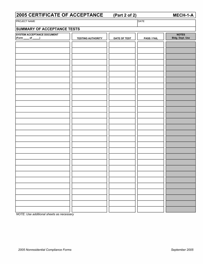
2005 CERTIFICATE OF ACCEPTANCE (Part 2 of 2) MECH-1-APROJECT NAME DATE
SUMMARY OF ACCEPTANCE TESTS
TESTING AUTHORITY DATE OF TEST PASS / FAILNOTES
Bldg. Dept. Use
NOTE: Use additional sheets as necessary
SYSTEM ACCEPTANCE DOCUMENT (Form ____ of _____)
2005 Nonresidential Compliance Forms September 2005

Ventilation System Acceptance Document MECH-2-ANJ.3.1, NJ.3.2 Form 1 of 2 __PROJECT NAME DATE
PROJECT ADDRESS
TESTING AUTHORITY TELEPHONE
VENTILATION SYSTEM NAME / DESIGNATION
Intent:
Construction Inspection
1 Instrumentation to perform test includes, but not limited to:a. Watchb. Means to measure airflow (hot wire anemometer or pitot tube)
2 Check one of the following:□ Variable Air Volume (VAV) - Check as appropriate:
a. Sensor used to control outdoor air flow must have calibration certificate or be field calibrated□ Calibration certificate (attach calibration certification)□ Field calibration (attach results)
□ Constant Air Volume (CAV) - Check as appropriate:□ System is designed to provide a fixed minimum OSA when the unit is on
Name:
Company:
Signature: Date:
:
___________________________________
_
__________________
_
2005 ACCEPTANCE REQUIREMENTS FOR CODE COMPLIANCE
__________________________ Checked by/Date
Enforcement Agency Use
___________________________________
___________________________________
Verify measured outside airflow CFM is within ± 10% of the total required outside airflow value found in the Standards Mechanical Plan (MECH-3, Column I), per 121(f).
Certification Statement: I certify that all statements are true on this MECH-2-A form including the PASS/FAIL Evaluation. I affirm I am eligible to sign this form under the provisions described in the Statement of Acceptance on form MECH-1-A
2005 Compliance Acceptance Forms September 2005

Ventilation System Acceptance Document MECH-2-ANJ.3.1, NJ.3.2 Form 2 of 2_PROJECT NAME DATE
2005 ACCEPTANCE REQUIREMENTS FOR CODE COMPLIANCE
A. Equipment Testing CAV VAVa. Constant or Variable Air Volume (CAV or VAV) - check appropriate columnb. Verify unit is not in economizer mode during test - check appropriate column
Step 1: CAV and VAV testing at full supply airflow 1 Drive boxes open (check)2 Measured outdoor airflow (cfm)3 Required outdoor airflow (cfm) (from MECH-3, column I)4 Time for outside air damper to stabilize after VAV boxes open (minutes)5 Return to initial conditions (check)
Step 2: VAV testing at reduced supply airflow1 Drive boxes to minimum (check)2 Measured outdoor airflow (cfm)3 Required outdoor airflow (cfm) (from MECH-3, column I)4 Time for outside air damper to stabilize after VAV boxes open (minutes)5 Return to initial conditions (check)
B. Testing Calculations & Results CAV VAVStep 1: % Outdoor Air = Measured outside air /Required outside air (Step1:2/Step1:3) % %
90%< %Outdoor Air > 110% to 90% = %Outoor Air = 110% Y / N Y / NOutside air damper position stabilizes within 15 minutes (Step 1:4 < 15 minutes) Y / N Y / N
Step 2: % Outdoor Air = Measured outside air /Required outside air (Step2:2/Step2:3)90%< %Outdoor Air > 110% to 90% = %Outoor Air = 110% Y / NOutside air damper position stabilizes within 15 minutes (Step 2:4 < 15 minutes) Y / N
Note: Shaded areas do not apply for particular test procedure
C. PASS / FAIL Evaluation (check one):□
□
PASS: All Construction Inspection responses are complete and Testing Calculations & Results responses are positive (Y - yes)
FAIL: Any Construction Inspection responses are incomplete OR there is one or more negative (N - no) responses in Testing Calculations & Results section. Provide explanation below. Use and attach additional pages if necessary.
2005 Compliance Acceptance Forms September 2005

Packaged HVAC Systems Acceptance Document MECH-3-ANJ.4.1 Form __ of __PROJECT NAME
PROJECT ADDRESS
TESTING AUTHORITY TELEPHONE
PACKAGED HVAC NAME / DESIGNATION
Construction Inspection
1 Instrumentation to perform test includes, but not limited to:a. None required
2 Installation□ Thermostat or zone temperature sensor is located within the zone that the HVAC system serves□ Thermostat or sensor is wired to the HVAC system correctly
3 Programming (check all of the following)□ Heating and cooling thermostats are capable of a 5°F deadband where cooling and heating
are at a minimum (§122b3)□ Occupied, unoccupied, and holiday schedule have been programmed.□ Pre-occupancy purge (at least lesser of minimum outside air or 3 ACH for one hour prior
to occupancy) programmed (§121.c.2)□ Set up and set back setpoints have been programmed as required
Name:
Company:
Signature: Date: __________________
: _
________________________________
________________________________
2005 ACCEPTANCE REQUIREMENTS FOR CODE COMPLIANCE
Intent: Verify that under a specific load whether in occupied or unoccupied condition, the system meets a specific sequence of operation.
__________________________ Checked by/Date Enforcement Agency
Use
DATE
Certification Statement: I certify that all statements are true on this MECH-3-A form including the PASS/FAIL Evaluation. I affirm I am eligible to sign this form under the provisions described in the Statement of Acceptance on form MECH-1-A
________________________________
_
2005 Mechanical Acceptance Forms April 2005

Packaged HVAC Systems Acceptance Document MECH-3-ANJ.4.1 Form __ of __PROJECT NAME
2005 ACCEPTANCE REQUIREMENTS FOR CODE COMPLIANCE
DATE
B. Equipment Testing Requirements Operating Modes
Heating load during occupied condition
No-load during occupied condition
Heating load during unoccupied condition
No-load during unoccupied condition
Manual override
Cooling load during occupied condition
Cooling load during unoccupied conditionCheck and verify the following for each simulation mode required A B C D E F G
1 Supply fan operates continually □ □ □ □2 Supply fan turns off □3 Supply fan cycles on and off □ □4 System reverts to "occupied" mode to satisfy any condition □5 System turns off when manual override time period expires □6 Gas-fired furnace, heat pump, or electric heater stages on □ □7 Neither heating or cooling is provided by the unit □ □8 No heating is provided by the unit □ □ □ □9 No cooling is provided by the unit □ □ □ □
10 Compressor stages on □ □11 Outside air damper is open to minimum position □ □ □ □12 Outside air damper closes completely □13 System returned to initial operating conditions after all tests have been completed
Note: Shaded areas do not apply for particular test procedure
C. Testing ResultsIndicate if Passed (P), Failed (F), or Not Applicable (X), fill in appropriate letter
D. PASS / FAIL Evaluation (check one):□
□
Y/N
PASS: All Construction Inspection responses are complete and all applicable Testing Results responses are "Passed" (P)FAIL: Any Construction Inspection responses are incomplete OR there is one or more "Failed" (F) responses in Testing Results section. Provide explanation below. Use and attach additional pages if necessary.
2005 Mechanical Acceptance Forms April 2005

Economizer Acceptance Document MECH-4-ANJ.7.1 Form __ of __PROJECT NAME DATE
PROJECT ADDRESS
TESTING AUTHORITY TELEPHONE
AIR ECONOMIZER NAME / DESIGNATION
Intent:
Construction Inspection
1 Instrumentation to perform test includes, but not limited to:a. Hand-held temperature probesb. Multi-meter capable of measuring ohms and milliamps
2 Test method (check one of the following):□
□ Economizer field installed and field tested.3 Installation (check all of the following first level boxes)□ Economizer high limit setpoint complies with Table 144-C per Standards Section 144(e)3□
□□□□
□□□□
Name:
Company:
Signature: Date
:
Second stage of cooling (Y2) from thermostat is separately wired to Y2 at HVAC unit
_
Certification Statement: I certify that all statements are true on this MECH-4-A form including the PASS/FAIL Evaluation. I affirm I am eligible to sign this form under the provisions described in the Statement of Acceptance on form MECH-1-A
HVAC unit has two-stage thermostat and the economizer is wired to be the first stage of control
First stage of cooling (Y1) from thermostat is separately wired to Y1 at HVAC unit
_
Sensor(s) used for economizer high limit control has factory calibration certificate or is field calibrated. Sensors include: outside air sensor only if single-point changeover; both outside and return air sensors if differential changeover control. Field calibration is not necessary if economizer is factory installed.
____________________________________
____________________________________
____________________________________ __________________
2005 ACCEPTANCE REQUIREMENTS FOR CODE COMPLIANCE
__________________________ Checked by/Date
Enforcement Agency Use
Economizer comes from HVAC system manufacturer installed by and has been factory calibrated and tested. Attach documentation and complete certification statement. No equipment testing required.
Stand-alone Control Systems:
Verify that an HVAC system uses outside air to satisfy space cooling loads when outside air conditions are acceptable.
System controls are wired correctly to ensure economizer is fully integrated (i.e. economizer will operate when mechanical cooling is enabled), if all boxes are checked for Standalone Control or EMS Control
System is provided with either barometric relief or powered relief (a relief fan or a return fan)
Economizer high limit control sensor(s) are properly installed
Two stages of cooling are not jumpered or wired together
Control sequence of operations will allow economizer to be integrated with cooling coil
EMS Controlled Systems:
2005 Nonresidential Acceptance Forms April 2005
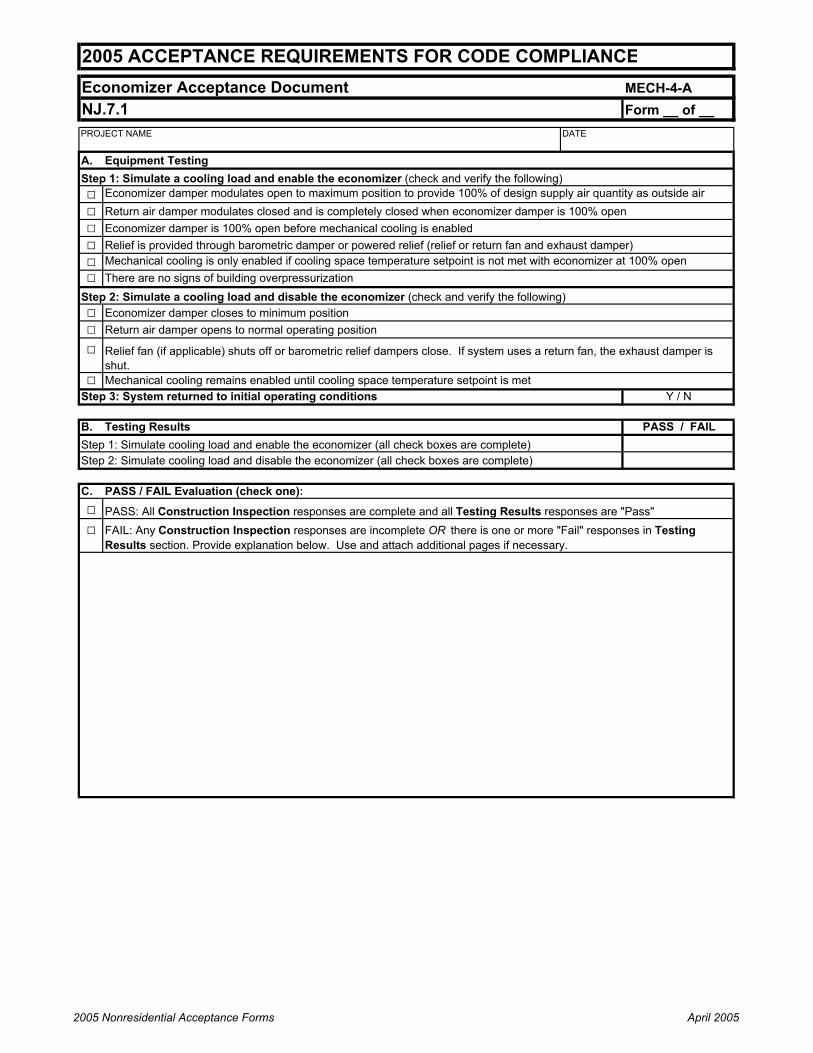
Economizer Acceptance Document MECH-4-ANJ.7.1 Form __ of __PROJECT NAME DATE
2005 ACCEPTANCE REQUIREMENTS FOR CODE COMPLIANCE
A. Equipment TestingStep 1: Simulate a cooling load and enable the economizer (check and verify the following)□□ Return air damper modulates closed and is completely closed when economizer damper is 100% open□ Economizer damper is 100% open before mechanical cooling is enabled□ Relief is provided through barometric damper or powered relief (relief or return fan and exhaust damper)□□ There are no signs of building overpressurization
Step 2: Simulate a cooling load and disable the economizer (check and verify the following)□ Economizer damper closes to minimum position□ Return air damper opens to normal operating position
□
□ Mechanical cooling remains enabled until cooling space temperature setpoint is metStep 3: System returned to initial operating conditions
B. Testing ResultsStep 1: Simulate cooling load and enable the economizer (all check boxes are complete)Step 2: Simulate cooling load and disable the economizer (all check boxes are complete)
C. PASS / FAIL Evaluation (check one):□□
PASS: All Construction Inspection responses are complete and all Testing Results responses are "Pass"FAIL: Any Construction Inspection responses are incomplete OR there is one or more "Fail" responses in Testing Results section. Provide explanation below. Use and attach additional pages if necessary.
Y / N
Economizer damper modulates open to maximum position to provide 100% of design supply air quantity as outside air
Mechanical cooling is only enabled if cooling space temperature setpoint is not met with economizer at 100% open
PASS / FAIL
Relief fan (if applicable) shuts off or barometric relief dampers close. If system uses a return fan, the exhaust damper is shut.
2005 Nonresidential Acceptance Forms April 2005

2005 Nonresidential Acceptance Forms April 2005
2005 ACCEPTANCE REQUIREMENTS FOR CODE COMPLIANCE MECH-5-ANJ.5.1Air Distribution Acceptance Document Part 1 of 3PROJECT NAME DATE TELEPHONE
PROJECT ADDRESS
TESTING AUTHORITY
AIR DISTRIBUTOR NAME / DESIGNATION PERMIT NUMBER __________________________ Checked by/Date
Enforcement Agency Use
Intent: New single zone supply ductwork shall not exceed a 6% leakage rate per §144(k) or §149D i, existing single zone ductwork shall not exceed 15% leakage or other compliance path per §149D ii or §149E.
Construction Inspection
1 Scope of test – New Buildings – this test required on New Buildings only if all checkboxes 1(a) through 1(c) are checked
Existing Buildings – this test required if 1(a) through 1(d) are checked Ductwork conforms to the following (note if any of these are not checked, then this test is not required):
□ 1a) Connected to a constant volume, single zone air conditioners, heat pumps, or furnaces □ 1b) Serves less than 5000 square feet of floor area □ 1c) Has more than 25% duct surface area located in one or more of the following spaces - Outdoors - A space directly under a roof where the U-factor of the roof is greater than U-factor of the ceiling
- A space directly under a roof with fixed vents or openings to the outside or unconditioned spaces
- An unconditioned crawlspace
□
- Other unconditioned spaces 1d) A duct is extended or any of the following replaced: air handler, outdoor condensing unit of a split system, cooling or heating coil, or the furnace heat exchanger.
2 Instrumentation to perform test includes: a. Duct Blaster
3 Material and Installation. Complying new duct systems shall have a checked box for all of the following categories a through f.
a. Choice of drawbands (check one of the following)
□ Stainless steel worm-drive hose clamps
□ UV-resistant nylon duct ties
□ b. Flexible ducts are not constricted in any way
□ c. Duct leakage tests performed before access to ductwork and connections are blocked
□ d. Joints and seams are not sealed with cloth back rubber adhesive tape unless used in combination with Mastic and drawbands
□ e. Duct R-values are verified R-8 per 124(a)
□ f. Ductwork located outdoors has insulation that is protected from damage and suitable for outdoor service
Certification Statement
I certify that all statements are true on this MECH-5-A form including the PASS/FAIL Evaluation. I affirm I am eligible to sign this form under the provisions described in the Statement of Acceptance on form MECH-1-A
Name:
Company: Signature: Date:

2005 Nonresidential Acceptance Forms April 2005
INSTALLER CERTIFICATION Part 2 of 3 MECH-5-A PROJECT NAME DATE
SITE ADDRESS PERMIT NUMBER
COPY TO: Building Department, Builder, Building Owner at Occupancy, HERS Provider
VERIFIED DUCT TIGHTNESS BY INSTALLER The installing contractor must pressure test every new HVAC systems that meet the requirements of Section 144(k) and every retrofit to existing HVAC systems that meet the requirements of section 149 D or E (see Scope of Test under Construction Inspection) RATED FAN FLOW (applies to all systems) Measured Values 1 Cooling capacity or for heating only units heating capacity a) Cooling capacity (for all units but heating only units) in tons b) Heating capacity (for heating only units) kBtu/h 2 Fan flow calculation a) Cooling capacity in tons [______(Line # 1a) x 400 cfm/ton] b) Heating only cap. kBtu/h [_____________(Line # 1b) x (21.7 cfm/kBtu/h)] 3 Total calculated supply fan flow 2(a) or 2(b) cfm
NEW CONSTRUCTION OR ENTIRE NEW DUCT SYSTEM ALTERATION: Duct Pressurization Test Results (CFM @ 25 Pa) 4 Enter Tested Leakage Flow in CFM: 5 Pass if Leakage Percentage� 6%: [______(Line # 4) /______(Line # 3)] x 100 % Pass Fail
ALTERATIONS: Pre-existing Duct System with Duct Alteration and/or HVAC Equipment Change-Out
6 Enter Tested Leakage Flow in CFM: Pre-Test of Existing Duct System Prior to Duct System Alteration and/or Equipment Change-Out.
7 Enter Tested Leakage Flow in CFM: Final Test of New Duct System or Altered Duct System for Duct System Alteration and/or Equipment Change-Out.
TEST OR VERIFICATION STANDARDS: For Altered Duct System and/or HVAC Equipment Change-Out Use one of the following Three Tests or Verification Standards for compliance:
8 Pass if Leakage Percentage � 15% Pass Fail [ _________________(Line # 7) / ________________(Line # 3)] x 100 % 9 Pass if Leakage Reduction Percentage � 60% Pass Fail
Leakage reduction = [1 - [___________(Line#7) / ___________(Line#6)]} x 100 %
10
Pass if all Accessible Leaks are sealed as confirmed by Visual Inspection and Verification by HERS rater (sampling rate 100%) Pass Fail
Pass if One of Lines #8 through # 10 pass Pass Fail
INSTALLER COMPLIANCE STATEMENT The building was: Tested at Final Tested at Rough-in
I, the undersigned, verify that the above diagnostic test results and the work I performed associated with the test(s) is in conformance with the requirements for compliance credit. I, the undersigned, also certify that the newly installed or retrofit Air-Distribution System Ducts, Plenums and Fans comply with Mandatory requirements specified in Section 124 of the 2005 Building Energy Efficiency Standards.
Name:
Company: Signature: Date:

2005 Nonresidential Acceptance Forms April 2005
INSTALLER CERTIFICATION Part 3 of 3 MECH-5-AHERS Rater: Telephone: Sample Group Number:
Certifying Signature: Sample building Number:
Firm: HERS Provider:
Copies to: Builder, Building Owner at Occupancy, Building Department (wet signature), HERS Provider For new buildings the HERS rater must test and field verify the first individual single zone package space conditioning equipment unit of each building. After the first unit passes the builder shall identify a group of up to seven package units in the building from which one sample will be selected for testing. If this first sampled unit fails the HERS rater must pick another package unit from the group for testing. If the second unit in the group does not pass the HERS rater must test all package units in the group. For existing buildings the HERS rater must pressure test one out of every seven units a contractor changes. Same rules apply for sampling above. This page must be filled out by the HERS rater for all tested and sampled buildings. If the installer has not tested every system and provided a MECH-5-A to the HERS rater sampling must not occur.
The unit was: Tested Approved as part of sample testing but was not tested As the HERS rater providing diagnostic testing and field verification, I certify that the building identified on this form complies with the diagnostic tested compliance requirements as checked on this form. The HERS rater must verify the distribution system on every new TESTED system to make sure that it is fully ducted and correct tape is used before a MECH-5-A may be released.
The installer has provided a completed MECH-5-A for every system in the group New distribution systems are fully ducted (i.e., does not use building cavities as plenums or platform returns in
lieu of ducts). In new duct systems, where cloth backed, rubber adhesive duct tape is installed, mastic and draw bands are used
in combination with cloth backed, rubber adhesive duct tape to seal leaks at duct connections.
RATED FAN FLOW (applies to all systems) Measured Values
1 Cooling capacity or for heating only units heating capacity a) Cooling capacity (for all units but heating only units) [_____ tons x 400 cfm/ton] b) Heating capacity (for heating only units) [_______ kBtuh x 21.7 cfm/kBtuh] 2 Total calculated supply fan flow 1(a) or 1(b) cfm
NEW CONSTRUCTION OR ENTIRE NEW DUCT SYSTEM ALTERATION: Duct Pressurization Test Results (CFM @ 25 Pa) 3 Enter Tested Leakage Flow in CFM: 4 Pass if Leakage Percentage� 6%: [ (Line # 3) / (Line # 2)] x 100 % � Pass � Fail ALTERATIONS: Pre-existing Duct System with Duct Alteration and/or HVAC Equipment Change-Out
5 Enter Tested Leakage Flow in CFM: Final Test of New Duct System or Altered Duct System for Duct System Alteration and/or Equipment Change-Out.
TEST OR VERIFICATION STANDARDS: For Altered Duct System and/or HVAC Equipment Change-Out, Use one of the following Three Tests or Verification Standards for compliance: 6 Pass if Leakage Percentage � 15% [________(Line # 5) / ________(Line # 2)] x 100 % � Pass � Fail
7
For systems certified by the installer as reducing leakage, pass if Leakage Reduction � 60%.
) LeakageTest -Pre Certified sInstaller' #6 Line _________( ) Leakage Tested HERS #5 Line _________(1Reduction Leakage −= ] x 100
% � Pass � Fail
8 Pass if all Accessible Leaks are sealed as confirmed by Visual Inspection and Verification by HERS rater (sampling rate 100%) � Pass � Fail
Pass if One of Lines # 6 through # 8 pass � Pass � Fail

Demand Control Ventilation Acceptance Document MECH-6-ANJ.8.1 Form __ of __PROJECT NAME DATE
PROJECT ADDRESS
TESTING AUTHORITY TELEPHONE
DCV NAME / DESIGNATION
Construction Inspection
1 Instrumentation to perform test may include, but not limited to:a. Calibrated hand-held CO2 analyzerb. Manufacturer's calibration kitc. Calibrated CO2/air mixtures
2 Installation□ The sensor is located in the room between 1 ft and 6 ft above the floor□ System controls are wired correctly to ensure proper control of outdoor air damper system
3 Documentation of all carbon dioxide control sensors includes (check one of the following):a. Calibration method
□ Factory-calibration certificate□ Field calibrated
b. Sensor accuracy□ Certified by manufacturer to be no more than +/- 75 ppm
Name:
Company:
Signature: Date:
-:_
___________________________________
___________________________________
___________________________________ __________________
Certification Statement: I certify that all statements are true on this MECH-6-A form including the PASS/FAIL Evaluation. I affirm I am eligible to sign this form under the provisions described in the Statement of Acceptance on form MECH-1-A
2005 ACCEPTANCE REQUIREMENTS FOR CODE COMPLIANCE
__________________________ Checked by/Date
Enforcement Agency Use
Intent: Verify outside air ventilation flow rate can be modulated automatically based on maintaining interior carbon dioxide concentration setpoint.
2005 Compliance Acceptance Forms April 2005

Demand Control Ventilation Acceptance Document MECH-6-ANJ.8.1 Form __ of __PROJECT NAME DATE
2005 ACCEPTANCE REQUIREMENTS FOR CODE COMPLIANCE
A. Equipment Testinga. Verify economizer controls disabledb. Outside air CO2 concentration (select one of the following)
□ Assumed to be 400 ppm ________ ppm□ Measured dynamically using CO2 sensor ________ ppm
c. Interior CO2 concentration setpoint (Outside CO2 concentration + 600 ppm) ________ ppmStep 1: Simulate a high CO2 load□
Step 2: Simulate a low CO2 load, or increase CO2 setpoint□ Outdoor air damper closes to minimum position during occupancy
Step 3: System returned to initial operating conditions
B. Testing ResultsStep 1: Simulate a high CO2 load (check box complete)Step 2: Simulate a low CO2 load (check box complete)
C. PASS / FAIL Evaluation (check one):□
□PASS: All Construction Inspection responses are complete and all Testing Results responses are "Pass"
FAIL: Any Construction Inspection responses are incomplete OR there is one or more "Fail" responses in Testing Results section. Provide explanation below. Use and attach additional pages if necessary.
Y / N
Outdoor air damper modulates opens per Standards toward maximum position to satisfy outdoor air requirements specified in Section 121(c)4, Table 121-A.
PASS / FAIL
2005 Compliance Acceptance Forms April 2005

Supply Fan VFD Acceptance Document MECH-7-ANJ.9.1 Form __ of __PROJECT NAME DATE
PROJECT ADDRESS
TESTING AUTHORITY TELEPHONE
VFD NAME / DESIGNATION
Construction Inspection
1 Instrumentation to perform test includes, but not limited to:a. Differential pressure gauge
2 Test preparation□
3 Documentation of all discharge static pressure sensors including (check one of the following):a. Factory-calibrated (proof required)
□ Factory-calibration certificateb. Field-calibrated
□ Calibration complete, all pressure sensors within 10% of calibrated reference sensor
Name:
Company:
Signature: Date:
::
___________________________________
___________________________________
___________________________________ __________________
Certification Statement: I certify that all statements are true on this MECH-7-A form including the PASS/FAIL Evaluation. I affirm I am eligible to sign this form under the provisions described in the Statement of Acceptance on form MECH-1-A
Disable discharge air temperature reset sequences to prevent unwanted interaction while performing tests
2005 ACCEPTANCE REQUIREMENTS FOR CODE COMPLIANCE
__________________________ Checked by/Date Enforcement Agency
Use
Intent: Verify that the supply fan in a variable air volume application modulates to meet air flow demand and operating parameters are within +/-10% of design value and/or setpoint.
2005 Nonresidential Acceptance Forms April 2005
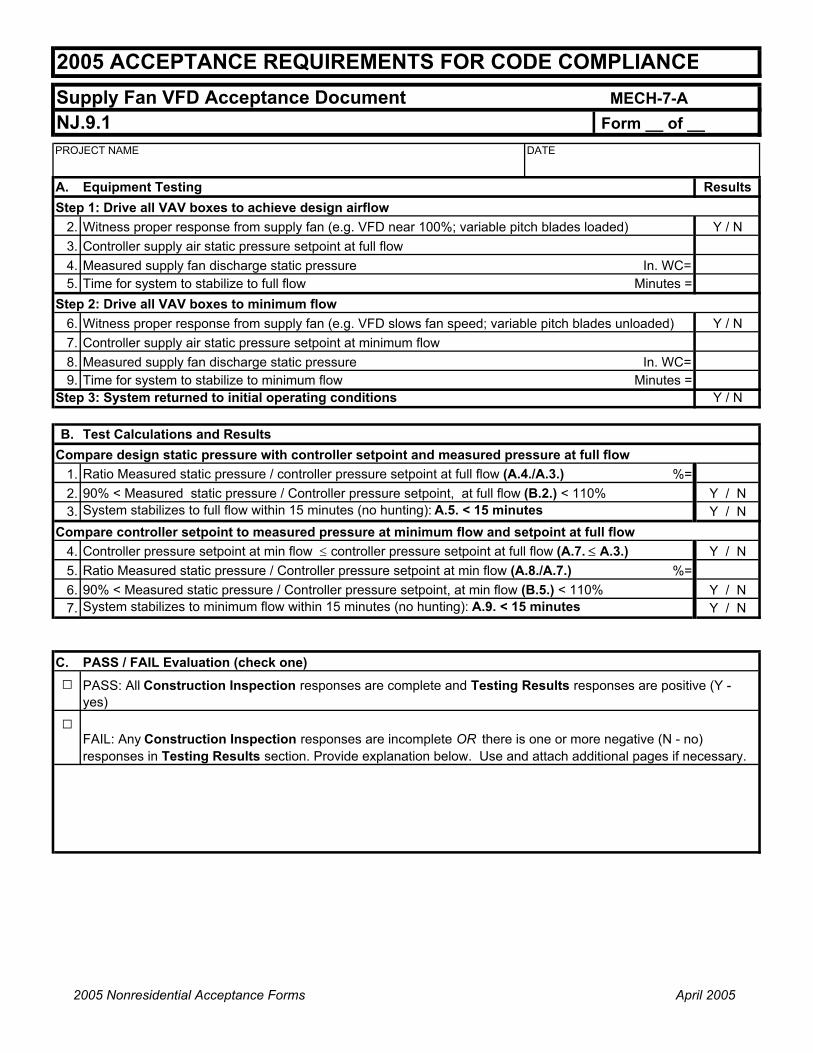
Supply Fan VFD Acceptance Document MECH-7-ANJ.9.1 Form __ of __PROJECT NAME DATE
2005 ACCEPTANCE REQUIREMENTS FOR CODE COMPLIANCE
A. Equipment Testing ResultsStep 1: Drive all VAV boxes to achieve design airflow
2. Witness proper response from supply fan (e.g. VFD near 100%; variable pitch blades loaded) Y / N3. Controller supply air static pressure setpoint at full flow4. Measured supply fan discharge static pressure In. WC=5. Time for system to stabilize to full flow Minutes =
Step 2: Drive all VAV boxes to minimum flow6. Witness proper response from supply fan (e.g. VFD slows fan speed; variable pitch blades unloaded) Y / N7. Controller supply air static pressure setpoint at minimum flow8. Measured supply fan discharge static pressure In. WC=9. Time for system to stabilize to minimum flow Minutes =
Step 3: System returned to initial operating conditions Y / N
B. Test Calculations and ResultsCompare design static pressure with controller setpoint and measured pressure at full flow
1. Ratio Measured static pressure / controller pressure setpoint at full flow (A.4./A.3.) %=2. 90% < Measured static pressure / Controller pressure setpoint, at full flow (B.2.) < 110% Y / N3. System stabilizes to full flow within 15 minutes (no hunting): A.5. < 15 minutes Y / N
Compare controller setpoint to measured pressure at minimum flow and setpoint at full flow4. Controller pressure setpoint at min flow ≤ controller pressure setpoint at full flow (A.7. ≤ A.3.) Y / N5. Ratio Measured static pressure / Controller pressure setpoint at min flow (A.8./A.7.) %=6. 90% < Measured static pressure / Controller pressure setpoint, at min flow (B.5.) < 110% Y / N7. System stabilizes to minimum flow within 15 minutes (no hunting): A.9. < 15 minutes Y / N
C. PASS / FAIL Evaluation (check one)□
□FAIL: Any Construction Inspection responses are incomplete OR there is one or more negative (N - no) responses in Testing Results section. Provide explanation below. Use and attach additional pages if necessary.
PASS: All Construction Inspection responses are complete and Testing Results responses are positive (Y - yes)
2005 Nonresidential Acceptance Forms April 2005

Hydronic System Control Acceptance Document MECH-8-ANJ.10.1 - NJ.10.5 Form __ of __PROJECT NAME DATE
PROJECT ADDRESS
TESTING AUTHORITY TELEPHONE
HYDRONIC SYSTEM NAME / DESIGNATION
Construction Inspection1 Instrumentation to perform tests include, but not limited to:
a. Differential pressure gaugeb. Portable temperature probe
2 Variable Flow Controls (VFC) and Automatic Isolation Controls (AIC) InspectionVFC AIC□ □ Valve and piping arrangements were installed per the design drawings to achieve the desired control
3 Supply Water Temperature Reset Controls Inspection□ Supply temperature sensors have been calibrated
□ Manufacturer's calibration certificates (attached)□ Site calibration within 2° F of temperature measurement with reference meter
□ Sensor locations are adequate to achieve accurate measurements□ Installed sensors comply with specifications
4 Water-loop Heat Pump Controls Inspection□ Valves were installed per the design drawings to achieve equipment isolation requirements□ All sensor locations comply with design drawings
5 Variable Frequency Drive Controls Inspection□ All valves, sensors, and equipment were installed per the design drawings□ Pressure sensors are calibrated
□ Manufacturer's calibration certificates (attached)□ Site calibration within 10% of pressure measurement with reference meter
Name:
Company:
Signature: Date:
::
2005 ACCEPTANCE REQUIREMENTS FOR CODE COMPLIANCE
Intent: Satisfy HVAC water pumping requirements per Section 144(j).
_
____________________________________
____________________________________
____________________________________ ____________
__________________________ Checked by/Date
Enforcement Agency Use
Certification Statement: I certify that all statements are true on this MECH-8-A form including the PASS/FAIL Evaluation. I affirm I am eligible to sign this form under the provisions described in the Statement of Acceptance on form MECH-1-A
2005 Nonresidential Acceptance Forms April 2005

Hydronic System Control Acceptance Document MECH-8-ANJ.10.1 - NJ.10.5 Form __ of __PROJECT NAME DATE
2005 ACCEPTANCE REQUIREMENTS FOR CODE COMPLIANCE
System IDA. System Type 1 2 3 4 5
1 Chilled water2 Heating hot water3 Water-loop heat pump loop4 Other (fill in blank):5 Other (fill in blank):
B. Select Acceptance Test (check all tests completed) 1 2 3 4 5□ Variable Flow Control - Alternate 1 (Flow measurement)□ Variable Flow Control - Alternate 2 (No flow measurement )□ Automatic Isolation Controls□ Supply Water Temperature Reset Controls□ Water-loop Heat Pump Controls - Alternate 1 (With Flow Meter)□ Water-loop Heat Pump Controls - Alternate 2 (Without Flow Meter)□ (Pump) Variable Frequency Drive Controls - Alternate 1(With Flow Meter)□ (Pump) Variable Frequency Drive Controls - Alternate 2(Without Flow Meter)
C. Equipment Testing RequirementsVerify and document the following (check applicable tests) 1 2 3 4 5NJ 10.1 Variable Flow Control - Alternate 1 (Flow measurement)
Step 1: Open all control valves.a. Measured system flow (gpm) GPM =b. Design system flow (gpm) GPM =c.
System operation achieves design conditions □ □ □ □ □Step 2: Initiate closure of control valvesa. Measured system flow (gpm) GPM =b. Design system flow (gpm) GPM =c. □ □ □ □ □d. □ □ □ □ □Step 3: System returned to initial operating conditions Y / N Y / N Y / N Y / N Y / NNJ.10.1 Variable Flow Control- Alternate 2 (No flow measurement)Step 1:Drive all valves shut and dead head pump against manual isolation valve
a. Measured pressure across the pump (ft. H20) ∆P=Step 2: Open manual isolation valve and measure pump DP with control valves closed
a. Measured pressure across the pump (ft. H20) ∆P=b. Both shutoff pressures are within +/- 5% of each other □ □ □ □ □
Step 3: System returned to initial operating conditions Y / N Y / N Y / N Y / N Y / NNJ.10.2 Automatic Isolation ControlsStep 1:Drive all valves shut and dead head pump against manual isolation valve
a. Measured pressure across the pump (ft. H20) ∆P=Step 2: Open manual isolation valve and start/stop each chiller or boiler one at a time
a. □ □ □ □ □b. □ □ □ □ □
Step 3: Stop all chillers and boilers on the hydronic loopa. Measured pressure across the pump (ft. H20) ∆P=b. Both shutoff pressures (1a and 3a) are within +/- 5% of each other □ □ □ □ □
Step 4: System returned to initial operating conditions Y / N Y / N Y / N Y / N Y / N
System ID
Verify automatic isolation valve closes fully when respective unit is OFFVerify automatic isolation valve opens fully when respective unit is ON
Design pump flow control strategy achieves flow reduction requirementsEnsure all valves operate correctly against the system pressure
2005 Nonresidential Acceptance Forms April 2005

Hydronic System Control Acceptance Document MECH-8-ANJ.10.1 - NJ.10.5 Form __ of __PROJECT NAME DATE
2005 ACCEPTANCE REQUIREMENTS FOR CODE COMPLIANCE
NJ.10.3 Supply Water Temperature Reset ControlsStep 1: Manually change design control variable to maximum setpoint
a. Reset temperature setpoint °F =b. Measured water temperature °F =c. Water temperature setpoint is reset to appropriate value □ □ □ □ □d. Actual water supply temperature meets setpoint □ □ □ □ □
Step 2: Manually change design control variable to minimum setpointa. Reset temperature setpoint °F =b. Measured water temperature °F =c. Water temperature setpoint is reset to appropriate value □ □ □ □ □d. Actual water supply temperature meets setpoint □ □ □ □ □
Step 3: System returned to initial operating conditions Y / N Y / N Y / N Y / N Y / NNJ 10.4 Water-loop Heat Pump Controls (for circulation pumps > 5 hp) - Alternate 1 (Flow measurement)
Step 1: Open all control valves
a. Measured system flow (gpm) GPM =
b. Design system flow (gpm) GPM =
c. System operation achieves design conditions +/- 5% (Step 1.a./Step 1.b.) □ □ □ □ □Step 2: Initiate shut-down sequence on each individual heat pumps
a. Isolation valves close automatically upon unit shut-down □ □ □ □ □b. Ensure all valves operate correctly at shut-off system pressure conditions □ □ □ □ □c. System flow reduced for each individual heat pump shut down □ □ □ □ □Step 3: System returned to initial operating conditions Y / N Y / N Y / N Y / N Y / NNJ.10.4 Water-loop Heat Pump Controls (for circulation pumps > 5 hp) - Alternate 2 (No flow measurement)Step 1:Drive all valves shut and dead head pump against manual isolation valve
a. Measured pressure across the pump (ft. H20) ∆P=Step 2: Open manual isolation valve and measure pump DP with automatic isolation valves closed
a. Measured pressure across the pump (ft. H20) ∆P=b. Both shutoff pressures are within +/- 5% of each other □ □ □ □ □
Step 3: System returned to initial operating conditions Y / N Y / N Y / N Y / N Y / NNJ.10.5 (Pump) Variable Frequency Drive Controls - Alternate 1 (With Flow Meters)
Step 1: Open all control valves
a. Measured system flow (gpm) GPM =
b. Design system flow (gpm) GPM =c.
kW =
d. System operation achieves design conditions +/- 5% (Step 1.a./Step 1.b.) □ □ □ □ □e. VFD operates near 100% speed at full flow □ □ □ □ □Step 2: Modulate control valves closed
a. Ensure all valves operate correctly at system pressure conditions □ □ □ □ □b. Witness proper response from VFD (speed decreases as valves close) □ □ □ □ □c. Time for system to stabilize Min =
d. System operation stabilizes within 5 min. after test procedures are initiated □ □ □ □ □Step 3: Adjust system operation to achieve 50% flow
a. Measured system flow (gpm) GPM =
b. Measured pump power at full flow kW =
c. %Power = part load kW/full load design kW (Step 3.b. / Step 1.c.) % =
d. VFD input power less than 30% of design □ □ □ □ □Step 4: Adjust to achieve flow rate where VFD is below min speed setpointa. VFD minimum setpoint Hz =
b. Ensure VFD maintains minimum speed setpoint □ □ □ □ □Step 5: System returned to initial operating conditions Y / N Y / N Y / N Y / N Y / N
Design pump power (estimated by motor HP/ motor efficiency x 0.746 kW/HP)
2005 Nonresidential Acceptance Forms April 2005

Hydronic System Control Acceptance Document MECH-8-ANJ.10.1 - NJ.10.5 Form __ of __PROJECT NAME DATE
2005 ACCEPTANCE REQUIREMENTS FOR CODE COMPLIANCE
NJ.10.5 (Pump) Variable Frequency Drive Controls - Alternate 2 (Without Flow Meters)Step 1: Open all control valves
a. Visually inspect a few valves to verify that they openb. Time for system to stabilize Min =c. System operation stabilizes within 5 min. after test procedures are initiated □ □ □ □ □d. VFD operates near 100% speed at full flow □ □ □ □ □e. Measured pressure at loop pressure sensor control point (psi or ft WC)
Step 2: Modulate control valves closeda. Visually inspect a few valves to verify that they close □ □ □ □ □b. Witness proper response from VFD (speed decreases as valves close) □ □ □ □ □c. Time for system to stabilize Min =d. System operation stabilizes within 5 min. after test procedures are initiated □ □ □ □ □e. Measured pressure at loop pressure sensor control point (psi or ft WC)f. Measured pressure with valves closed ≤ pressure with valves open □ □ □ □ □
Step 3: System returned to initial operating conditions Y / N Y / N Y / N Y / N Y / N
D. PASS / FAIL Evaluation (check one):□
□ FAIL: Any applicable Construction Inspection responses are incomplete OR there is one or more unchecked box for an applicable test in the Equipment Testing Requirements section. Provide explanation below. Use and attach additional pages if necessary.
PASS: All applicable Construction Inspection responses are complete and applicable Equipment Testing Requirements check boxes are compete.
2005 Nonresidential Acceptance Forms April 2005

Appendix B Page B-1
2005 Nonresidential Compliance Manual March 2005
Appendix B Excerpts from the Appliance Standards
Note: For equipment that is covered by both §112 of the Building Energy Efficiency Standards and the Appliance Efficiency Regulations, the requirements of §112 supersede the requirements in the Appliance Efficiency Regulations

Appendix B Page B-2
2005 Nonresidential Compliance Manual March 2005
Note: Maximum energy consumption standards for refrigerator-freezers with internal freezers are same as those for refrigerator-freezers with top-mounted freezers.
(2) See Section 1605.3(a) for energy efficiency and energy design standards for freezers with volume exceeding 30 ft3 that are consumer products, wine chillers that are consumer products, commercial refrigerators including but not limited to refrigerated bottled or canned beverage vending machines, commercial refrigerator-freezers, commercial freezers, commercial ice-makers, and water dispensers.
(b) Room Air Conditioners, Room Air-Conditioning Heat Pumps, Packaged Terminal Air Conditioners, and Packaged Terminal Heat Pumps.
(1) Room Air Conditioners and Room Air-Conditioning Heat Pumps. The EER of room air conditioners and room air-conditioning heat pumps that are manufactured on or after the effective dates shown shall be not less than the applicable values shown in Table B-2. The EER of room air conditioners and room air-conditioning heat pumps that are labeled for use at more than one voltage shall be not less than the applicable values shown in Table B-2 at each of the labeled voltages.

Appendix B Page B-3
2005 Nonresidential Compliance Manual March 2005
Table B-2 Standards for Room Air Conditioners and Room Air-Conditioning Heat Pumps
ApplianceLouvere
dSides
CoolingCapacity(Btu/hr)
Minimum EER
EffectiveJanuary 1, 1990
EffectiveOctober 1, 2000
Room Air Conditioner Yes < 6,000 8.0 9.7 Room Air Conditioner Yes 6,000 – 7,999 8.5 9.7 Room Air Conditioner Yes 8,000 – 13,999 9.0 9.8 Room Air Conditioner Yes 14,000 – 19,999 8.8 9.7 Room Air Conditioner Yes 20,000 8.2 8.5 Room Air Conditioner No < 6,000 8.0 9.0 Room Air Conditioner No 6,000 – 7,999 8.5 9.0 Room Air Conditioner No 8,000 – 19,999 8.5 8.5 Room Air Conditioner No 20,000 8.2 8.5 Room Air Conditioning Heat Pump Yes < 20,000 8.5 9.0
Room Air Conditioning Heat Pump Yes 20,000 8.5 8.5
Room Air Conditioning Heat Pump No < 14,000 8.0 8.5
Room Air Conditioning Heat Pump No 14,000 8.0 8.0
Casement-Only Room Air Conditioner Either Any * 8.7
Casement-SliderRoom Air Conditioner Either Any * 9.5
*Casement-only room air conditioners and casement-slider room air conditioners are not separate product classes under standards effective January 1, 1990. Such appliances, if manufactured before October 1, 2000, are subject to the applicable standards in Table B-2 for the other room air conditioners and room air-conditioning heat pumps based on capacity and the presence or absence of louvered sides.
(2) Packaged Terminal Air Conditioners and Packaged Terminal Heat Pumps. The EER and COP, as applicable, of packaged terminal air conditioners and packaged terminal heat pumps shall be not less than the applicable values shown in Table B-3.

Appendix B Page B-4
2005 Nonresidential Compliance Manual March 2005
Table B-3 Standards for Packaged Terminal Air Conditioners and Packaged Terminal Heat Pumps
Appliance Mode CoolingCapacity(Btu/hr)
Minimum EER or COP
7,000 8.88 EER 7,000 and
15,000 10.0 (0.00016 x Cap.) EER
Packaged terminal air conditioners and packaged terminal heat pumps
Cooling
15,000 7.6 EER Packaged terminal heat pumps Heating Any 1.3 + [0.16 (10.0 – 0.00016 x Cap.)]
COP
Cap. = cooling capacity (Btu/hr)
(c) Central Air Conditioners.
(1) Central Air Conditioners Other than Water-Source Heat Pumps Below 240,000 Btu/hr. The EER, SEER, COP, and HSPF, as applicable, of all central air conditioners shall be not less than the applicable values shown in Tables C-2, C-3, C-4, and C-5.

Appendix B Page B-5
2005 Nonresidential Compliance Manual March 2005
Table C-2 Standards for Single Phase Air-Cooled Air Conditioners with
Cooling Capacity Less than 65,000 Btu per Hour and Single Phase Air-Source Heat Pumps with Cooling Capacity Less than 65,000 Btu per Hour, Not Subject to EPAct
Minimum Efficiency
Effective January 1, 1995 Effective January 23, 2006Appliance
Minimum SEER
Minimum HSPF
Minimum SEER
Minimum HSPF
Split system air conditioners 10.0 — 13.0 —
Split system heat pumps 10.0 6.8 13.0 7.7
Single package air conditioners 9.7 — 13.0 —
Single package heat pumps 9.7 6.6 13.0 7.7
Space constrained air conditioners – split system 10.0 — reserved —
Space constrained heat pumps – split system 10.0 6.8 reserved reserved
Space constrained air conditioners – single package 9.7 — reserved —
Space constrained heat pumps – single package 9.7 6.6 reserved reserved

Appendix B Page B-6
2005 Nonresidential Compliance Manual March 2005
Table C-3 Standards for Air-Cooled Air Conditioners and
Air-Source Heat Pumps Subject to EPAct
Appliance CoolingCapacity(Btu/hr)
System Type Minimum Efficiency
< 65,000 * Split system 10.0 SEER < 65,000 * Single package 9.7 SEER 65,000 and
< 135,000 All 8.9 EER Air-cooled unitary air conditioners and heat pumps (cooling mode) 135,000
and< 240,000
All 8.5 EER
< 65,000 * Split system 6.8 HSPF < 65,000 * Single package 6.6 HSPF 65,000 and
< 135,000 All 3.0 COP at 47 F db
Air-cooled unitary air-conditioning heat pumps (heating mode) 135,000
and< 240,000
All 2.9 COP
* Three phase models only.
Table C-4 Standards for Evaporatively-Cooled Air Conditioners
Minimum EER
ApplianceCoolingCapacity
(Btu per hour) Effective
January 1, 1994
EffectiveOctober 29,
2003
EffectiveOctober 29,
2004
< 65,000 9.3 12.1 12.1
65,000 and < 135,000 10.5 11.51 11.51
Evaporatively-cooled air conditioners
135,000 < 240,000 9.6 9.6 11.0
1 Deduct 0.2 from the required EER for units with heating sections other than electric resistance heat.

Appendix B Page B-7
2005 Nonresidential Compliance Manual March 2005
Table C-5 Standards for Water-Cooled Air Conditioners and Water-Source Heat Pumps
Minimum Efficiency
EffectiveJanuary 1,
1995
EffectiveOctober 29,
2003
EffectiveOctober 29,
2004Appliance
CoolingCapacity
(Btu per hour) Minimum
EER COP Minimum
EER COP Minimum
EER COP Water-cooled air conditioners < 17,000 9.3 — 12.1 — 12.1 —
Water-sourceheat pumps < 17,000 9.3 3.8 11.2 4.2 11.2 4.2
Water-cooled air conditioners
17,000 and < 65,000 9.3 — 12.1 — 12.1 —
Water-sourceheat pumps
17,000 and < 65,000 9.3 3.8 12.0 4.2 12.0 4.2
Water-cooled air conditioners
65,000 and < 135,000 10.5 — 11.51 — 11.5 —
Water-sourceheat pumps
65,000 and < 135,000 10.5 3.8 12.0 4.2 12.0 4.2
Water-cooled air conditioners
135,000 and < 240,000 9.6 — 9.6 — 11.0 —
Water-sourceheat pumps
135,000 and < 240,000 9.6 2.9 9.6 2.9 9.6 2.9
1 Deduct 0.2 from the required EER for units with heating sections other than electric resistance heat.
(2) Water-Source Heat Pumps below 135,000 Btu per Hour. The California standard for water-source heat pumps equal to or greater than 65,000 Btu/hr and less than 135,000 Btu/hr is identical to the federal standards shown in Table C-5.The California standard for water- source heat pumps less than 65,000 Btu/hr is shown in Table C-7 in Section 1605.3(c)(1).
(3) Gas-fired Air Conditioners and Heat Pumps. There is no energy efficiency standard or energy design standard for gas-fired air conditioners or gas-fired heat pumps.
(4) Other Central Air Conditioners. See Sections 1605.2(c) and 1605.3(c) for energy efficiency standards for other central air conditioners.

Appendix B Page B-8
2005 Nonresidential Compliance Manual March 2005
(d) Spot Air Conditioners, Evaporative Coolers, Ceiling Fans, Whole House Fans, and Residential Exhaust Fans.
There is no energy efficiency standard or energy design standard for spot air conditioners, evaporative coolers, ceiling fans, whole house fans, or residential exhaust fans.
(e) Gas and Oil Space Heaters.
(1) Gas Wall Furnaces, Gas Floor Furnaces, and Gas Room Heaters. The AFUE of gas wall furnaces, gas floor furnaces, and gas room heaters shall be not less than the applicable values shown in Table E-2.
Table E-2 Standards for Gas Wall Furnaces, Floor Furnaces, and Room Heaters
Appliance DesignType
Capacity(Btu per hour)
Minimum AFUE (%)
Wall furnace Fan 42,000 73
Wall furnace Fan > 42,000 74 Wall furnace Gravity 10,000 59
Wall furnace Gravity > 10,000 12,000 60
Wall furnace Gravity > 12,000 15,000 61
Wall furnace Gravity > 15,000 19,000 62
Wall furnace Gravity > 19,000 27,000 63
Wall furnace Gravity > 27,000 46,000 64
Wall furnace Gravity > 46,000 65 Floor furnace All 37,000 56
Floor furnace All > 37,000 57 Room heater All 18,000 57
Room heater All > 18,000 and 20,000
58
Room heater All > 20,000 and 27,000
63
Room heater All > 27,000 and 46,000
64
Room heater All > 46,000 65
(2) Central Gas Furnaces, Central Gas Boilers, Central Oil Furnaces, and Central Oil Boilers. The AFUE, thermal efficiency, and combustion efficiency, as applicable, of central gas furnaces, central gas boilers, central oil furnaces, and central oil boilers shall be not less than the applicable values shown in Tables E-3 and E-4.

Appendix B Page B-9
2005 Nonresidential Compliance Manual March 2005
Table E-3 Standards for Gas- and Oil-Fired Central Boilers
Minimum Efficiency (%)
ApplianceRatedInput
(Btu/hr) AFUECombustion Efficiency
at Maximum Rated Capacity
Gas steam boilers with single phase electrical supply
<300,000 75 —
All other boilers with single phase electrical supply
<300,000 80 —
Gas packaged boilers 300,000 — 80
Oil packaged boilers 300,000 — 83
Table E-4 Standards for Gas- and Oil-Fired Central Furnaces
Minimum Efficiency (%) Appliance
RatedInput
(Btu/hr) AFUE Thermal Efficiency
Mobile home gas and oil central furnaces with single phase electrical supply
<225,000 75 —
All other gas and oil central furnaces with single phase electrical supply
<225,000 78 —
Gas central furnaces 225,000 — 80
Oil central furnaces 225,000 — 81
(3) Infrared Gas Heaters. There is no energy efficiency standard or energy design standard for infrared gas heaters.
(f) (4) Other Gas and Oil Space Heaters. See Section 1605.3(e) for standards for boilers, central furnaces, duct furnaces, and unit heaters that are not federally-regulated consumer products or federally-regulated commercial and industrial equipment.

Appendix B Page B-10
2005 Nonresidential Compliance Manual March 2005
Water Heaters.
(1) Large Water Heaters. The thermal efficiency and standby loss of large water heaters manufactured during the applicable time period shall be not less than the applicable values shown in Tables F-2, F-3, and F-4.
Table F-2 Standards for Large Water Heaters
(Effective January 1, 1994 through October 28, 2003)
Fuel InputRating
Volume(gallons)
Input to VolumeRatio
(Btu/gal)
Minimum Thermal
Efficiency(%)
Maximum Standby Loss
(%/hour)1
Gas
> 75,000 and155,000(Btu/hour)
All < 4,000 78 1.3 + 114/V
Oil
> 105,000 and155,000(Btu/hour)
All < 4,000 78 1.3 + 114/V
Gas, oil > 155,000 (Btu/hour) 140 < 4,000 78 1.3 + 95/V
Gas, oil > 155,000 (Btu/hour) > 140 < 4,000 78 1.3 + 95/V2
Gas > 200,000 (Btu/hour) < 10 4,000 80 —
Oil > 210,000 (Btu/hour) < 10 4,000 80 —
Gas > 200,000 (Btu/hour) 10 4,000 77 2.3 + 67/V
Oil > 210,000 (Btu/hour) 10 4,000 77 2.3 + 67/V
Electric > 12 kW 140 < 4,000 — 0.3 + 27/V Electric > 12 kW > 140 < 4,000 — 0.3 + 27/V2
Electric > 12 kW < 10 4,000 80 — Electric > 12 kW 10 4,000 77 2.3 + 67/V
1 Volume (V) = measured storage volume in gallons2 Storage-type water heaters with volume exceeding 140 gallons need not meet the
standby loss requirement if they are thermally insulated to at least R-12.5 and if a standing pilot light is not used.

Appendix B Page B-11
2005 Nonresidential Compliance Manual March 2005
Table F-3 Standards for Large Water Heaters
(New Standards Effective October 29, 2003)
Appliance Category Size or Rating
Minimum Thermal
Efficiency(%)
Maximum Standby Loss1,2
< 155,000 Btu/hr 80 Q/800 + 110 V Btu/hr Gas storage water heaters
< 4,000 Btu/hr/gal > 155,000 Btu/hr 80 Q/800 + 110 V Btu/hr
Gasinstantaneouswater heaters
4,000 Btu/hr/gal 10 gal 80 Q/800 + 110 V Btu/hr
< 155,000 Btu/hr 78 Q/800 + 110 V Btu/hr Oil storage water heaters
< 4,000 Btu/hr/gal > 155,000 Btu/hr 78 Q/800 + 110 V Btu/hr
< 10 gal 80 – Oilinstantaneouswater heaters
4,000 Btu/hr/gal 10 gal 78 Q/800 + 110 V Btu/hr
Gas hot water supply boilers
4,000 Btu/hr/gal 10 gal 80 Q/800 + 110 V Btu/hr
Oil hot water supply boilers
4,000 Btu/hr/gal 10 gal 78 Q/800 + 110 V Btu/hr
Electric water heaters All All No
requirement0.30 + 27/V % Per hour
1 Standby loss is based on a 70º F temperature difference between stored water and ambient requirements. In the standby loss equations, V is the rated volume in gallons, and Q is the nameplate input rate in Btu/hr.
2 Water heaters and hot water supply boilers having more than 140 gallons of storage capacity are not required to meet the standby loss requirement if the tank surface is thermally insulated toR-12.5, if a standing pilot light is not installed, and for gas- or oil-fired storage water heaters, there is a flue damper or fan-assisted combustion.

Appendix B Page B-12
2005 Nonresidential Compliance Manual March 2005
Table F-4 Standards for Large Water Heaters
(Existing Standards Remaining in Effect On and After October 29, 2003)
Fuel InputRating
Volume(gallons)
Input to VolumeRatio
(Btu/gal)
Minimum Thermal
Efficiency (%)
Maximum Standby Loss
(%/hour)1,2
Gas > 200,000 (Btu/hour) < 10 4,000 80 Not applicable
Electric > 12 kW 140 < 4,000 Not applicable 0.3 + 27/V Electric > 12 kW > 140 < 4,000 Not applicable 0.3 + 27/V Electric > 12 kW < 10 4,000 80 Not applicable Electric > 12 kW 10 4,000 77 2.3 + 67/V
1 Volume (V) = measured storage volume in gallons 2 Storage-type water heaters with volume exceeding 140 gallons need not meet the
standby loss requirement if they are thermally-insulated to at least R-12.5 and if a standing pilot light is not used.
(2) Small Water Heaters. The energy factor of all small water heaters that are federally-regulated consumer products, (other than booster water heaters, hot water dispensers, and mini-tank electric water heaters) shall be not less than the applicable values shown in Table F-5.
Table F-5 Standards for Small Federally-Regulated Water Heaters
Minimum Energy FactorAppliance Effective
April 15, 1991 Effective
January 20, 2004 Gas-fired storage-type water heaters 0.62 – (.0019 x V) 0.67 – (.0019 x V)
Oil-fired water heaters (storage and instantaneous) 0.59 – (.0019 x V) 0.59 – (.0019 x V)
Electric storage water heaters (excluding tabletop water heaters) 0.93 - (.00132 x V) 0.97 - (.00132 x V)
Electric tabletop water heaters 0.93 - (.00132 x V) 0.93 - (.00132 x V) Gas-fired instantaneous water heaters 0.62 – (.0019 x V) 0.62 – (.0019 x V)
Electric instantaneous water heaters (excluding tabletop water heaters)
0.93 - (.00132 x V) 0.93 - (.00132 x V)
Heat pump water heaters 0.93 - (.00132 x V) 0.97 - (.00132 x V)
V = rated volume in gallons.

Appendix B Page B-13
2005 Nonresidential Compliance Manual March 2005
(3) Booster Water Heaters. There is no energy efficiency standard or energy design standard for booster water heaters.
(4) Other Water Heaters. See Section 1605.3(f) for standards for other water heaters.
(5) Combination Space-Heating and Water-Heating Appliances. See Section 1605.3(e) for standards for combination space-heating and water-heating appliances.
(g) Pool Heaters, Residential Pool Pumps, and Portable Electric Spas.
(1) Energy Efficiency Standard for Gas-Fired Pool Heaters and Oil-Fired Pool Heaters. The thermal efficiency of gas-fired pool heaters and oil-fired pool heaters shall be not less than 78 percent.
(2) Energy Efficiency Standards for Heat Pump Pool Heaters. See Section 1605.3(g) for energy efficiency standards for heat pump pool heaters.
(3) Energy Efficiency Standard for Electric Resistance Pool Heaters. There is no energy efficiency standard for electric resistance pool heaters.
(4) Energy Design Standards for Pool Heaters. See Section 1605.3(g) for energy design standards for pool heaters.
(5) Energy Efficiency Standards for Portable Electric Spas. See Section 1605.3(g) for energy efficiency standards for portable electric spas.
(6) Energy Efficiency Standards and Energy Design Standards for Residential Pool Pumps. See Section 1605.3(g) for energy efficiency standards and energy design standards for residential pool pumps.
(h) Plumbing Fittings.
(1) Plumbing Fittings Except Tub Spout Diverters and Commercial Pre-rinse Spray Valves. The flow rate of showerheads, lavatory faucets, kitchen faucets, lavatory replacement aerators, kitchen replacement aerators, wash fountains, and metering faucets shall be not greater than the applicable values shown in Table H-1. Showerheads shall also meet the requirements of ASME/ANSI Standard A112.18.1M-1996, 7.4.4(a).
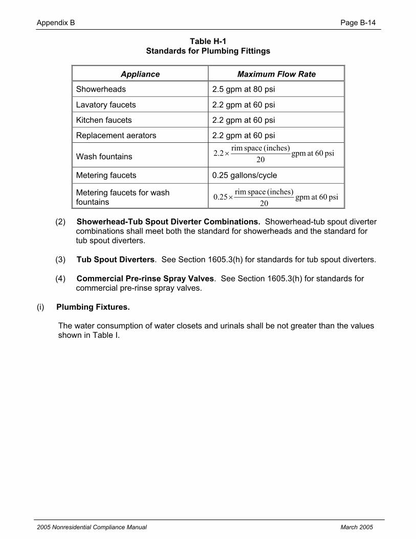
Appendix B Page B-14
2005 Nonresidential Compliance Manual March 2005
Table H-1 Standards for Plumbing Fittings
Appliance Maximum Flow Rate
Showerheads 2.5 gpm at 80 psi
Lavatory faucets 2.2 gpm at 60 psi
Kitchen faucets 2.2 gpm at 60 psi
Replacement aerators 2.2 gpm at 60 psi
Wash fountains psi60atgpm20
(inches)spacerim2.2
Metering faucets 0.25 gallons/cycle
Metering faucets for wash fountains psi60atgpm
20(inches)spacerim25.0
(2) Showerhead-Tub Spout Diverter Combinations. Showerhead-tub spout diverter combinations shall meet both the standard for showerheads and the standard for tub spout diverters.
(3) Tub Spout Diverters. See Section 1605.3(h) for standards for tub spout diverters.
(4) Commercial Pre-rinse Spray Valves. See Section 1605.3(h) for standards for commercial pre-rinse spray valves.
(i) Plumbing Fixtures.
The water consumption of water closets and urinals shall be not greater than the values shown in Table I.

Appendix B Page B-15
2005 Nonresidential Compliance Manual March 2005
Table I Standards for Plumbing Fixtures
Appliance Maximum Gallons per Flush
Gravity tank-type water closets 1.6
Flushometer tank water closets 1.6
Electromechanical hydraulic water closets 1.6
Blowout water closets 3.5
Trough-type urinals 16
(inches)lengthtrough
Other urinals 1.0
(j) Fluorescent Lamp Ballasts and Replacement Fluorescent Lamp Ballasts.
(1) The ballast efficacy factor of the following types of fluorescent lamp ballasts shall be not less than the applicable values shown in Table J-1, except that fluorescent lamp ballasts (i) designed for dimming, (ii) designed for use in ambient temperatures of 0° F or less, or (iii) with a power factor of less than 0.90 and designed for use only in residential buildings are excluded:
(A) replacement fluorescent lamp ballasts manufactured on or before June 30, 2010;
(B) fluorescent lamp ballasts manufactured on or after January 1, 1990;
(C) fluorescent lamp ballasts sold by the manufacturer on or after April 1, 1990; and
(D) fluorescent lamp ballasts incorporated into a luminaire by a luminaire manufacturer on or after April 1, 1991.

Appendix B Page B-16
2005 Nonresidential Compliance Manual March 2005
Table J-1 Standards for Fluorescent Lamp Ballasts and Replacement Fluorescent Lamp Ballasts
Application for Operation of
Ballast Input Voltage
Total Nominal Lamp Watts
Minimum Ballast Efficacy
Factorone F40T12
lamp120 or
277 40 1.805
120 80 1.060 two F40T12 lamps 277 80 1.050
two F96T12 lamps
120 or 277 150 0.570
two F96T12HO lamps
120 or 277 220 0.390
(2) The ballast efficacy factor of the following types of fluorescent lamp ballasts shall be not less than the applicable values shown in Table J-2, except that fluorescent lamp ballasts (i) designed for dimming to 50 percent or less of maximum output, (ii) designed for use with two F96T12HO lamps at ambient temperatures of –20° F or less and for use in an outdoor sign, (iii) with a power factor of less than 0.90 and designed and labeled for use only in residential buildings, or (iv) designated as a replacement ballast as defined in Section 1602(j) are excluded:
(A) fluorescent lamp ballasts manufactured on or after April 1, 2005;
(B) fluorescent lamp ballasts sold by the manufacturer on or after July 1, 2005;
(C) replacement fluorescent lamp ballasts manufactured after June 30, 2010; and
(D) fluorescent lamp ballasts incorporated into a luminaire by a luminaire manufacturer on or after April 1, 2006.
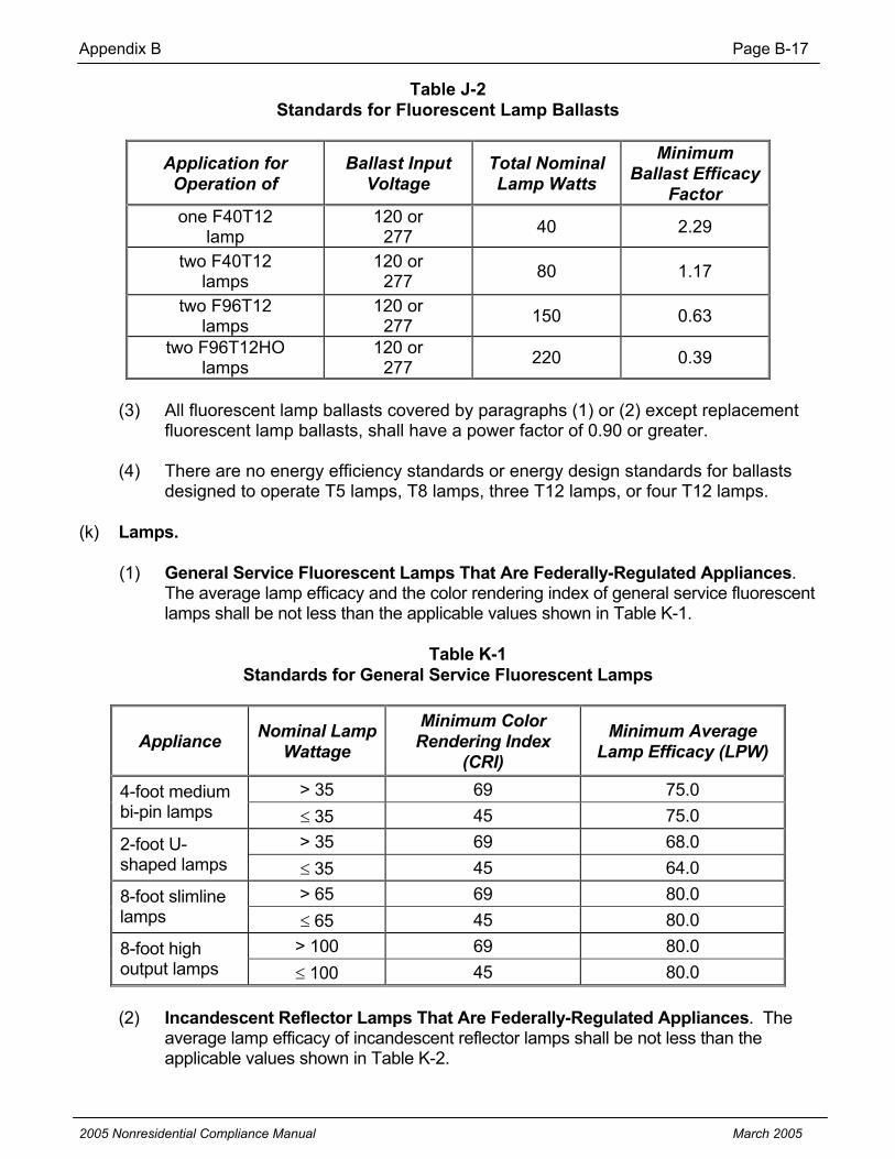
Appendix B Page B-17
2005 Nonresidential Compliance Manual March 2005
Table J-2 Standards for Fluorescent Lamp Ballasts
Application for Operation of
Ballast Input Voltage
Total Nominal Lamp Watts
Minimum Ballast Efficacy
Factorone F40T12
lamp120 or
277 40 2.29
two F40T12 lamps
120 or 277 80 1.17
two F96T12 lamps
120 or 277 150 0.63
two F96T12HO lamps
120 or 277 220 0.39
(3) All fluorescent lamp ballasts covered by paragraphs (1) or (2) except replacement fluorescent lamp ballasts, shall have a power factor of 0.90 or greater.
(4) There are no energy efficiency standards or energy design standards for ballasts designed to operate T5 lamps, T8 lamps, three T12 lamps, or four T12 lamps.
(k) Lamps.
(1) General Service Fluorescent Lamps That Are Federally-Regulated Appliances.The average lamp efficacy and the color rendering index of general service fluorescent lamps shall be not less than the applicable values shown in Table K-1.
Table K-1 Standards for General Service Fluorescent Lamps
Appliance Nominal Lamp Wattage
Minimum Color Rendering Index
(CRI)
Minimum Average Lamp Efficacy (LPW)
> 35 69 75.0 4-foot medium bi-pin lamps 35 45 75.0
> 35 69 68.0 2-foot U-shaped lamps 35 45 64.0
> 65 69 80.0 8-foot slimline lamps 65 45 80.0
> 100 69 80.0 8-foot high output lamps 100 45 80.0
(2) Incandescent Reflector Lamps That Are Federally-Regulated Appliances. The average lamp efficacy of incandescent reflector lamps shall be not less than the applicable values shown in Table K-2.

Appendix B Page B-18
2005 Nonresidential Compliance Manual March 2005
Table K-2 Standards for Incandescent Reflector Lamps
Nominal Lamp Wattage Minimum Average Lamp Efficacy (LPW)
40-50 10.5
51-66 11.0
67-85 12.5
86-115 14.0
116-155 14.5
156-205 15.0
(3) See Section 1605.3(k) for energy efficiency standards for lamps that are state-regulated.
(l) Emergency Lighting.
See Section 1605.3(l) for energy efficiency standards for illuminated exit signs.
(m) Traffic Signal Modules and Traffic Signal Lamps.
See Section 1605.3(m) for energy efficiency standards for traffic signal modules and traffic signal lamps.
(n) Luminaires.
See Section 1605.3(n) for energy efficiency standards and energy design standards for luminaires.
(o) Dishwashers.
The energy factor of dishwashers that are consumer products shall be not less than the applicable values shown in Table O.

Appendix B Page B-19
2005 Nonresidential Compliance Manual March 2005
Table O Standards for Dishwashers
Appliance Minimum Energy Factor (cycles/kWh)
Compact dishwashers 0.62
Standard dishwashers 0.46
(p) Clothes Washers.
(1) Energy Efficiency Standards for Residential Clothes Washers. The energy factor and modified energy factor of clothes washers that are consumer products shall be not less than the applicable values shown in Table P-2.
Table P-2 Energy Efficiency Standards for Residential Clothes Washers
Minimum Modified Energy Factor [ft3/(kWh/cycle)]*
Appliance
Minimum Energy Factor [ft3/(kWh/cycle)]Effective May 14, 1994 Through December 31,
2003Effective
January 1, 2004 Effective
January 1, 2007
Top-loading compact clothes washers 0.90 0.65 0.65
Top-loading standard clothes washers 1.18 1.04 1.26
Top-loading, semi-automatic N/A1 N/A1 N/A1
Front-loading clothes washers N/A1 1.04 1.26
Suds-saving N/A1 N/A1 N/A1
1Must have an unheated rinse water option. *The sum of the machine electrical energy consumption, the hot water energy consumption, and the energy required for removal of the remaining moisture in the wash load.
(2) Energy Design Standard for Top-Loading Semi-Automatic Clothes Washers and Suds-Saving Clothes Washers. Top-loading semi-automatic clothes washers that are consumer products and suds-saving clothes washers that are consumer products shall have an unheated rinse water option and do not need to meet the Modified Energy Factor standard shown in Table P-2.
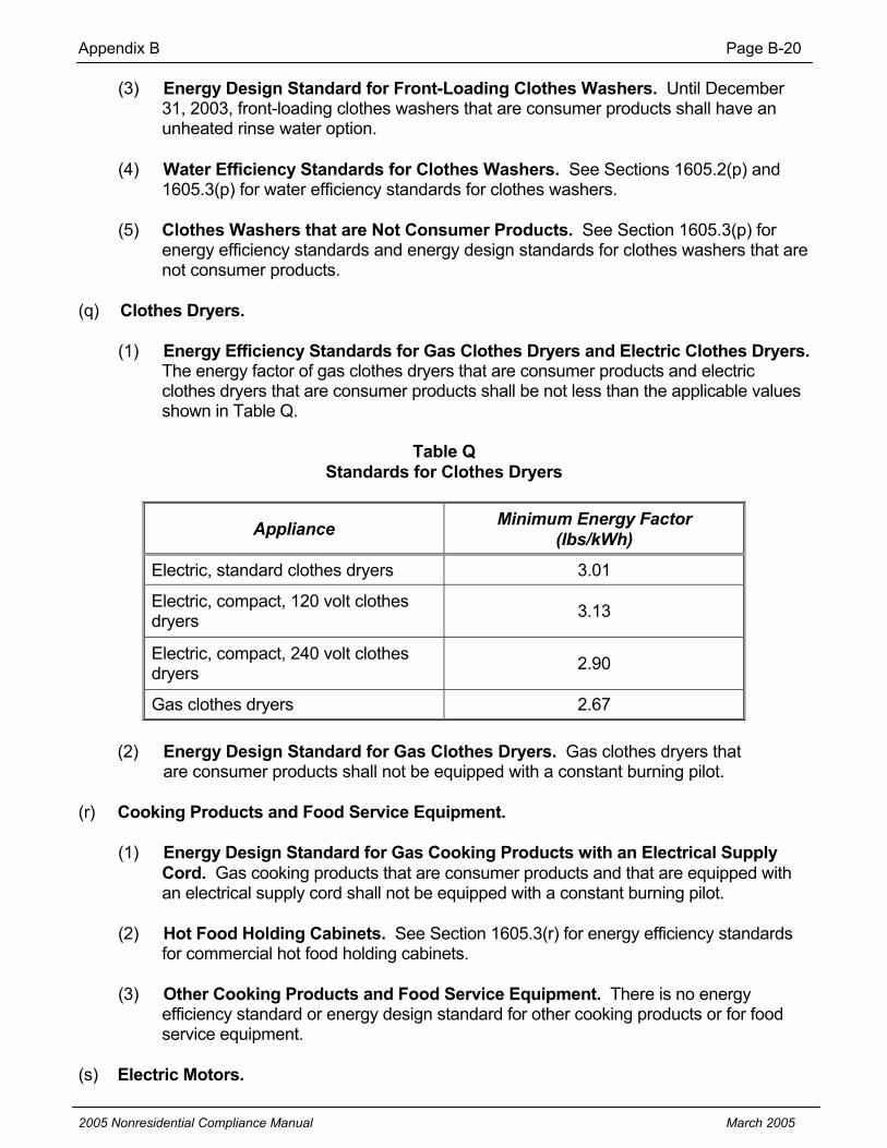
Appendix B Page B-20
2005 Nonresidential Compliance Manual March 2005
(3) Energy Design Standard for Front-Loading Clothes Washers. Until December 31, 2003, front-loading clothes washers that are consumer products shall have an unheated rinse water option.
(4) Water Efficiency Standards for Clothes Washers. See Sections 1605.2(p) and 1605.3(p) for water efficiency standards for clothes washers.
(5) Clothes Washers that are Not Consumer Products. See Section 1605.3(p) for energy efficiency standards and energy design standards for clothes washers that are not consumer products.
(q) Clothes Dryers.
(1) Energy Efficiency Standards for Gas Clothes Dryers and Electric Clothes Dryers.The energy factor of gas clothes dryers that are consumer products and electric clothes dryers that are consumer products shall be not less than the applicable values shown in Table Q.
Table Q Standards for Clothes Dryers
Appliance Minimum Energy Factor (lbs/kWh)
Electric, standard clothes dryers 3.01
Electric, compact, 120 volt clothesdryers 3.13
Electric, compact, 240 volt clothes dryers 2.90
Gas clothes dryers 2.67
(2) Energy Design Standard for Gas Clothes Dryers. Gas clothes dryers that are consumer products shall not be equipped with a constant burning pilot.
(r) Cooking Products and Food Service Equipment.
(1) Energy Design Standard for Gas Cooking Products with an Electrical Supply Cord. Gas cooking products that are consumer products and that are equipped with an electrical supply cord shall not be equipped with a constant burning pilot.
(2) Hot Food Holding Cabinets. See Section 1605.3(r) for energy efficiency standards for commercial hot food holding cabinets.
(3) Other Cooking Products and Food Service Equipment. There is no energy efficiency standard or energy design standard for other cooking products or for food service equipment.
(s) Electric Motors.

Appendix B Page B-21
2005 Nonresidential Compliance Manual March 2005
(1) Except as provided in paragraph (2) of this subsection, the nominal full-load efficiency of all electric motors that are federally-regulated commercial and industrial equipment shall be not less than the applicable values shown in Table S.
Table S Standards for Electric Motors
Minimum Nominal Full-Load Efficiency
Open Motors Closed Motors
Motor Horsepow
er 6 poles 4 poles 2 poles 6 poles 4 poles 2 poles1 <1.5 80.0 82.5 . . . 80.0 82.5 75.5 1.5 <2 84.0 84.0 82.5 85.5 84.0 82.5 2 <3 85.5 84.0 84.0 86.5 84.0 84.0 3 <5 86.5 86.5 84.0 87.5 87.5 85.5 5 <7.5 87.5 87.5 85.5 87.5 87.5 87.5 7.5 <10 88.5 88.5 87.5 89.5 89.5 88.5 10 <15 90.2 89.5 88.5 89.5 89.5 89.5 15 <20 90.2 91.0 89.5 90.2 91.0 90.2 20 <25 91.0 91.0 90.2 90.2 91.0 90.2 25 <30 91.7 91.7 91.0 91.7 92.4 91.0 30 <40 92.4 92.4 91.0 91.7 92.4 91.0 40 <50 93.0 93.0 91.7 93.0 93.0 91.7 50 <60 93.0 93.0 92.4 93.0 93.0 92.4 60 <75 93.6 93.6 93.0 93.6 93.6 93.0 75
<100
93.6 94.1 93.0 93.6 94.1 93.0
100 <125
94.1 94.1 93.0 94.1 94.5 93.6
125 <150
94.1 94.5 93.6 94.1 94.5 94.5
150 <200
94.5 95.0 93.6 95.0 95.0 94.5
200 94.5 95.0 94.5 95.0 95.0 95.0
(2) The standards in this subsection do not apply to electric motors that are (A) installed and sold within another appliance that is within the scope of this Article or (B) installed in low-rise residential buildings.
(t) Distribution Transformers.
See Section 1605.3(t) for energy efficiency standards for distribution transformers.
(u) Power Supplies and Consumer Audio and Video Equipment.

Appendix B Page B-22
2005 Nonresidential Compliance Manual March 2005
See Section 1605.3(u) for energy efficiency standards for power supplies and consumer audio and video equipment.
The following documents are incorporated by reference in Section 1605.1
ASME/ANSI A112.8.1M-1996 Plumbing Fixture Fittings
Copies available from: ASME International Three Park Avenue New York, NY 10016-5990 www.asme.org Phone: (800) THE-ASME (U.S./Canada) 95-800-843-2763 (Mexico) (973) 882-1167 (Outside North America)
NOTE: Authority cited: Sections 25213, 25218(e), 25402(a)-(c), 25553(b) and 25960, Public Resources Code.
Reference: Sections 25216.5(d), 25402(a)-(c), 25553(b) and 25960, Public Resources Code.

Appendix B Page B-23
2005 Nonresidential Compliance Manual March 2005
See Section 1605.1(b) for energy efficiency standards for room air conditioners, room air conditioning heat pumps, packaged terminal air conditioners, and packaged terminal heat pumps that are federally-regulated consumer products or federally-regulated commercial and industrial equipment.
(c) Central Air Conditioners.
(1) Energy Efficiency Standards for Water-Source Heat Pumps, Ground Water-Source Heat Pumps, and Ground-Source Heat Pumps. The EER and COP for water-source heat pumps, ground water-source heat pumps, and ground-source heat pumps shall be not less than the applicable values shown in Tables C-7 and C-8.
Table C-7 Standards for Water-Source and Ground Water-Source Heat Pumps
Manufactured On or After January 1, 1993, but Before October 29, 2003
Standard Rating Low Temperature Rating
ApplianceCoolingCapacity(Btu/hr) Rating Condition
Minimum
Standard
Rating Condition
Minimum Standard
Water-sourceheat pumps (cooling)
< 65,000 85º F entering water temperature 10.0 EER
75º F entering watertemperature
10.2 EER
Water-sourceheat pumps (cooling)
65,000 <
135,000
85º F entering water temperature 10.5 EER — —
Ground water-source heat pumps (cooling)
<135,000
70º F entering water temperature 11.0 EER
50º F entering watertemperature
11.5 EER
Ground water-source heat pumps (heating)
All70º F entering watertemperature1,2
3.5 COP 50º F entering watertemperature1,2
3.0 COP
1 Air entering indoor section 70º F db/60º F wb (maximum). 2 Water flow rate per manufacturer’s specifications.

Appendix B Page B-24
2005 Nonresidential Compliance Manual March 2005
Table C-8 Standards for Ground Water-Source and Ground-Source Heat Pumps
Manufactured On or After October 29, 2003
Appliance Rating Condition Minimum Standard
Ground water-source heat pumps (cooling)
59º F entering water temperature 16.2 EER
Ground water-source heat pumps (heating)
50º F entering water temperature 3.6 COP
Ground-source heat pumps (cooling) 77º F entering brine temperature 13.4 EER
Ground-source heat pumps (heating) 32º F entering brine temperature 3.1 COP
(2) Energy Efficiency Standards for Computer Room Air Conditioners. The EER of air-cooled, water-cooled, glycol-cooled, and evaporatively-cooled computer room air conditioners manufactured on or after the effective dates shown, shall be not less than the applicable values shown in Tables C-9 and C-10.
Table C-9 Standards for Air-Cooled Computer Room Air Conditioners
Minimum EER (Btu/watt-hour)
ApplianceCoolingCapacity(Btu/hr)
EffectiveJanuary 1,
1998
EffectiveMarch 1, 2003
EffectiveJanuary 1,
2004
EffectiveJanuary 1,
2006
< 65,000 8.3 9.3 10.7 11.0
65,000 and <135,000 7.7 8.3 10.4 10.4
Air-cooledcomputer room air conditioners
135,000 and < 240,000 — 7.9 10.2 10.2

Appendix B Page B-25
2005 Nonresidential Compliance Manual March 2005
Table C-10 Standards for Water-Cooled, Glycol-Cooled, and Evaporatively-Cooled
Computer Room Air Conditioners
Minimum EER (Btu/watt-hour)
ApplianceCoolingCapacity(Btu/hr)
EffectiveJanuary 1,
1998
EffectiveMarch 1, 2003
EffectiveOctober29, 2004
EffectiveOctober29, 2006
< 65,000 8.1 8.3 11.1
11.1
65,000 and <135,000 8.4 9.5 10.5 10.5
Water-cooled,glycol-cooled,andevaporatively-cooledcomputer room air conditioners
135,000 and< 240,000
— 8.6 8.6 10.0
(3) Energy Efficiency Standards for Large Air-Cooled Unitary Air Conditioners. The EER of air-cooled unitary air conditioners manufactured on or after on or after the effective dates shown, shall be not less than the applicable values shown in Table C-11.
Table C-11 Standards for Large Air-Cooled Packaged Air Conditioners
Minimum StandardsAppliance Cooling Capacity (Btu/hr) Effective October 1,
2006Effective January 1,
2010Air-cooled unitary air conditioners
240,000 and < 760,000
10.0 EER 10.5 EER
(4) Gas-fired Air Conditioners and Heat Pumps. There is no energy efficiency standard or energy design standard for gas-fired air conditioners or gas-fired heat pumps.
(5) Other Central Air Conditioners. See Sections 1605.1(c) and 1605.2(c) for energy efficiency standards for central air conditioners that are federally-regulated consumer products or federally-regulated commercial and industrial equipment.

Appendix B Page B-26
2005 Nonresidential Compliance Manual March 2005
(d) Spot Air Conditioners, Evaporative Coolers, Ceiling Fans, Whole House Fans, and Residential Exhaust Fans.
There is no energy efficiency standard or energy design standard for spot air conditioners, evaporative coolers, ceiling fans, whole house fans, and residential exhaust fans.
(e) Gas and Oil Space Heaters.
(1) Boilers, Central Furnaces, Duct Furnaces, and Unit Heaters.(A) The efficiency of boilers, central furnaces, duct furnaces, and unit
heaters shall be not less than, and the standby loss shall be not greater than, the applicable values shown in Tables E-5, E-6, and E-7.
Table E-5 Standards for Boilers
Standards
Appliance Output(Btu/hr)
MinimumAFUE %
Minimum Combustion
Efficiency % *
Maximum Standby Loss (watts)
Gas steam boilers with 3-phase electrical supply
< 300,000 75 — —
All other boilers with 3-phase electrical supply
< 300,000 80 — —
Natural gas, non-packaged boilers 300,000 — 80 147
LPG Non-packaged boilers 300,000 — 80 352
Oil, non-packaged boilers 300,000 — 83 —
*At both maximum and minimum rated capacity, as provided and allowed by the controls.

Appendix B Page B-27
2005 Nonresidential Compliance Manual March 2005
Table E-6 Standards for Furnaces
Appliance Application Minimum Efficiency %
Mobile Home 75 AFUE Central furnaces with 3-phase electrical supply< 225,000 Btu/hour All others
78 AFUE or 80 Thermal Efficiency (at manufacturer’s
option)
Table E-7 Standards for Duct Furnaces and Unit Heaters
StandardsMinimum Thermal Efficiency %1
Appliance Fuel At maximum
rated capacity At minimum
ratedcapacity
Maximum Energy
Consumptionduring standby
(watts)
Duct furnaces Natural gas 80 75 10 Duct furnaces LPG2 80 75 147 Unit heaters Natural gas 80 74 10 Unit heaters LPG2 80 74 147 Unit heaters Oil 81 81 N/A 1 As provided and allowed by the controls. 2 Designed expressly for use with LPG.
(B) Natural gas-fired unit heaters and duct furnaces manufactured on or after January 1, 2006, shall have either power venting or an automatic flue damper.
(2) Oil Wall Furnaces, Oil Floor Furnaces and Infrared Gas Space Heaters. There are no energy efficiency standards or energy design standards for oil wall furnaces, oil floor furnaces, or infrared gas space heaters.
(3) Combination Space-Heating and Water-Heating Appliances.
(A) If part of a combination space-heating and water-heating appliance is a water heater, that part shall comply with the applicable water heater standards in Sections 1605.1(f) and 1605.3(f).
(B) If part of a combination space-heating and water-heating appliance is a furnace, boiler, or other space heater, that part shall comply with the applicable furnace, boiler, or other space heater standards in Sections 1605.1(e) and 1605.3(e).

Appendix B Page B-28
2005 Nonresidential Compliance Manual March 2005
(C) Water heaters that are federally-regulated appliances, and that are contained in combination space-heating and water-heating appliances that are federally-regulated appliances, are required only to meet the standard for the applicable type of water heater, and are not required to meet any standard for space heaters.
(4) Other Gas and Oil Space Heaters. See Section 1605.1(e) for standards for gas and oil space heaters that are federally-regulated.
(f) Water Heaters.
(1) Hot Water Dispensers and Mini-Tank Electric Water Heaters. The standby loss of hot water dispensers and mini-tank electric water heaters manufactured on or after March 1, 2003 shall be not greater than 35 watts.
EXCEPTION: This subsection does not apply to any water heater: (1) that is within the scope of 42 U.S.C. Sections 6292(a)(4) or 6311(1)(F), (2) that has a rated storage volume of less than 20 gallons, and (3) for which there is no federal test method applicable to that type of water heater.
(2) Small Water Heaters that are Not Federally-Regulated Consumer Products.The energy factor of small water heaters manufactured on or after March 1, 2003 that are not federally-regulated consumer products, other than hot water dispensers, booster water heaters, and mini-tank electric water heaters, shall be not less than the applicable values shown in Table F-6.
EXCEPTION: This subsection does not apply to any water heater (1) that is within the scope of 42 U.S.C. Sections 6292(a)(4) or 6311(1)(F), (2) that has a rated storage volume of less than 20 gallons, and (3) for which there is no federal test method applicable to that type of water heater.

Appendix B Page B-29
2005 Nonresidential Compliance Manual March 2005
Table F-6 Standards for Small Water Heaters that are Not Federally-Regulated Consumer Products
Appliance EnergySource Input Rating
RatedStorageVolume
(gallons)
Minimum Energy Factor1
Storagewater heaters Gas 75,000 Btu/hr < 20 0.62 – (.0019 x V)
Storagewater heaters Gas 75,000 Btu/hr > 100 0.62 – (.0019 x V)
Storagewater heaters Oil 105,000
Btu/hr > 50 0.59 – (.0019 x V)
Storagewater heaters Electricity 12 kW > 120 0.93 – (.00132 x
V) Instantaneous Water Heaters
Gas 50,000 Btu/hr Any 0.62 – (.0019 x V)
Instantaneous Water Heaters
Gas 200,000 Btu/hr 2 0.62 – (.0019 x V)
Instantaneous Water Heaters
Oil 210,000 Btu/hr Any 0.59 – (.0019 x V)
InstantaneousWaterHeaters
Electricity 12 kW Any 0.93 – (.00132 x V)
1Volume (V) = rated storage volume in gallons.
(3) Energy Efficiency Standards for Combination Space-Heating and Water-Heating Appliances. See Section 1605.3(e)(3) for standards for combination space-heating and water-heating appliances.
(4) Energy Efficiency Standards for Water Heaters. See Section 1605.1(f) for standards for water heaters that are federally-regulated consumer products or federally-regulated commercial and industrial equipment.
(5) Energy Efficiency Standards for Booster Water Heaters. There is no energy efficiency standard or energy design standard for booster water heaters.

Appendix B Page B-30
2005 Nonresidential Compliance Manual March 2005
(g) Pool Heaters, Residential Pool Pumps, and Portable Electric Spas.
(1) Energy Design Standard for Natural Gas Pool Heaters. Natural gas pool heaters shall not be equipped with constant burning pilots.
(2) Energy Design Standard for All Pool Heaters. All pool heaters shall have a readily accessible on-off switch that is mounted on the outside of the heater and that allows shutting off the heater without adjusting the thermostat setting.
(3) Energy Efficiency Standard for Heat Pump Pool Heaters. For heat pump pool heaters manufactured on or after March 1, 2003, the average of the coefficient of performance (COP) at Standard Temperature Rating and the coefficient of performance (COP) at Low Temperature Rating shall be not less than 3.5.
(4) Energy Efficiency Standards for Gas and Oil Pool Heaters. See Section 1605.1(g) for energy efficiency standards for gas and oil pool heaters that are federally-regulated consumer products.
(5) Residential Pool Pumps.
(A) Motor Efficiency. Pool pump motors manufactured on or after January 1, 2006 may not be split-phase or capacitor start – induction run type.
(B) Two-Speed Capability.
(i) Pump Motors. Pool pump motors with a capacity of 1 HP or more which are manufactured on or after January 1, 2008, shall have the capability of operating at two or more speeds with a low speed having a rotation rate that is no more than one-half of the motor’s maximum rotation rate.
(ii) Pump Controls. Pool pump motor controls manufactured on or after January 1, 2008 shall have the capability of operating the pool pump at at least two speeds. The default circulation speed shall be the lowest speed, with a high speed override capability being for a temporary period not to exceed one normal cycle.
(6) Portable Electric Spas. The standby power of portable electric spas manufactured on or after January 1, 2006, shall be not greater than 5(V2/3)Watts where V = the total volume, in gallons.

Appendix B Page B-31
2005 Nonresidential Compliance Manual March 2005
(h) Plumbing Fittings.
(1) Tub Spout Diverters. The leakage rate of tub spout diverters shall be not greater than the applicable values shown in Table H-2.
Table H-2 Standards for Tub Spout Diverters
Maximum Leakage Rate Appliance Testing Conditions Effective
March 1, 2003
When new 0.01 gpm Tub spout diverters After 15,000 cycles of
diverting 0.05 gpm
(2) Showerhead-Tub Spout Diverter Combinations. Showerhead-tub spout diverter combinations shall meet both the standard for showerheads and the standard for tub spout diverters.
(3) Commercial Pre-rinse Spray Valves.
(A) The flow rate of commercial pre-rinse spray valves manufactured on or after January 1, 2006, shall be equal to or less than 1.6 gpm at 60 psi.
(B) Commercial pre-rinse spray valves manufactured on or after January 1, 2006 shall be capable of cleaning 60 plates at an average time of not more than 30 seconds per plate.
(4) Other Plumbing Fittings. See Section 1605.1(h) for energy efficiency standards for plumbing fittings that are federally-regulated consumer products.
(i) Plumbing Fixtures.
See Section 1605.1(i) for energy efficiency standards for plumbing fixtures that are federally-regulated consumer products.
(j) Fluorescent Lamp Ballasts.
See Section 1605.1(j) for energy efficiency standards for fluorescent lamp ballasts that are federally-regulated consumer products.

Appendix B Page B-32
2005 Nonresidential Compliance Manual March 2005
(k) Lamps.
(1) See Section 1605.1(k) for energy efficiency standards for lamps that are federally-regulated consumer products.
(2) Energy Efficiency Standards for State-Regulated General Service Incandescent Lamps.
The power use of state-regulated general service incandescent lamps manufactured on or after the effective dates shown in Table K-3, shall be no greater than the applicable values shown in Table K-3.
Table K-3 Standards for State-Regulated General Service Incandescent Lamps
Maximum Power Use (Watts) Lamp Type January 1, 2006
Full Spectrum or Enhanced Spectrum, such as Chromalux™, Reveal™, and Enrich™
No requirement
Other Frost or Clear (0.0500 * Lumens) + 21 Other Soft White (0.0480 * Lumens) + 23 Vibration Service Lamps No requirement
(l) Emergency Lighting.
Energy Standards for Illuminated Exit Signs. The input power, luminance contrast, minimum luminance, average luminance and maximum to minimum luminance ratio of illuminated exit signs manufactured on or after March 1, 2003 shall meet the requirements of Table L.
Table L Standards for Exit Signs
Standard Requirement
Input power < 5 watts per face
Luminance contrast > 0.8
Minimum luminance >8.6 candelas/meter2 measured at normal (0º) and 45º viewing angles
Average luminance > 15 candelas/meter2 measured at normal (0º) and 45º viewing angles
Maximum to minimum luminance ratio < 20:1 measured at normal (0º) and 45º viewing angles

Appendix B Page B-33
2005 Nonresidential Compliance Manual March 2005
(1) Energy Efficiency Standard and Energy Design Standard for Torchieres. Torchieres manufactured on or after March 1, 2003, shall not consume more than 190 watts and shall not be capable of operating with lamps that total more than 190 watts. Torchieres manufactured on or after January 1, 2006, shall not use more than 190 watts. A torchiere shall be deemed to use more than 190 watts if any commercially available lamp or combination of lamps can be inserted in its socket(s) and cause the torchiere to draw more than 190 watts when operated at full brightness.
(1) Energy Efficiency Standard for Metal Halide Luminaires. Metal halide luminaires, manufactured on or after the effective dates shown in Table N-1, shall meet the requirements shown in Table N-1.
Table N-1 Standards for Metal Halide Luminaires
LampPosition
Lamp Rating Effective Date
Requirements
Vertical 150-500 Watts Jan. 1, 2006 Luminaires shall not contain a probe-start metal halide ballast.
Notes: Fixtures are covered if they are capable of operating lamps that fall within the range of included lamp wattages. Vertical includes both base-up and base-down products. Vertical includes products rated for use within 15o of vertical.
(3) Energy Efficiency Standards for Under-Cabinet Luminaires. Under-cabinet luminaires that are equipped with T-8 fluorescent lamps and that are designed to be attached to office furniture and that are manufactured on or after January 1, 2006 shall be equipped with ballasts that have a ballast efficacy factor not less than the applicable values shown in Table N-2.
EXCEPTIONS:
1. Luminaires equipped with T-8 ballasts designed for dimming.
2. Luminaires that are:
(a) specifically and exclusively designed for use in applications where electromagnetic interference from electronic ballasts would interfere with critical, sensitive instrumentation and equipment such as medical imaging devices; and
(b) clearly, legibly, and permanently labeled, in at least 12 point type and in a place likely to be seen by the purchaser and the installer, "This fixture is intended exclusively for use in applications where critical, sensitive equipment would be adversely affected by electronic lamp ballast electromagnetic radiation”.

Appendix B Page B-34
2005 Nonresidential Compliance Manual March 2005
Table N-2 Standards for Under-Cabinet Luminaires
Lamp Length (inches) Minimum Ballast Efficacy Factor (BEF) for one lamp
Minimum Ballast Efficacy Factor (BEF) for two lamps
29 4.70 2.80 >29 and 35 3.95 2.30 >35 and 41 3.40 1.90 >41 and 47 3.05 1.65
>47 2.80 1.45
(m) Dishwashers.
See Section 1605.1(o) for energy efficiency standards for dishwashers that are federally-regulated consumer products.
(n) Commercial Clothes Washers.
(1) Energy and Water Efficiency Standards for Commercial Front-Loading and Commercial Top-Loading Automatic Clothes Washers. The modified energy factor and water factor of commercial front-loading and commercial top-loading automatic clothes washers manufactured on or after the dates indicated in Table P-4 that are not consumer products shall be not less than (modified energy factor) and not more than (water factor) the applicable values shown in Table P-4.
Table P-4 Standards for Commercial Clothes Washers
ApplianceClothes Container
CompartmentCapacity (ft3)
Minimum Modified Energy
FactorEffective
January 1, 2005
Maximum Water Factor
EffectiveJanuary 1, 2007
Front-loading clothes washers
< 3.5 ft3 1.26 9.5
Top-loading clothes washers
< 1.6 ft3
1.6 ft3 and < 4.0 ft3
0.65
1.26
9.5
9.5
(2) Energy Design Standard for Commercial Top-Loading Semi-Automatic Clothes Washers and Commercial Suds-Saving Clothes Washers. Commercial top-loading semi-automatic clothes washers and commercial suds-saving clothes washers manufactured on or after January 1, 2005 shall have an unheated rinse water option.

Appendix B Page B-35
2005 Nonresidential Compliance Manual March 2005
(3) Other Clothes Washers. See Sections 1605.1(p) and 1605.2(p) for energy efficiency standards and energy design standards for clothes washers that are federally-regulated consumer products.
(q) Clothes Dryers.
See Section 1605.1(q) for energy efficiency standards and energy design standards for clothes dryers that are federally-regulated consumer products.
(r) Cooking Products and Food Service Equipment.(1) Energy Standards for Food Service Equipment. There is no energy efficiency
standard or energy design standard for food service equipment other than commercial hot food holding cabinets.
(2) Energy Efficiency Standards for Commercial Hot Food Holding Cabinets. Theidle energy rate of commercial hot food holding cabinets manufactured on or after January 1, 2006 shall be no greater than 40 Watts per cubic foot of measured interior volume.
(3) Cooking Products. See Section 1605.1(r) for the energy design standard for cooking products that are federally-regulated consumer products.
(s) Electric Motors.See Section 1605.1(s) for energy efficiency standards for electric motors that are federally-regulated commercial and industrial equipment.
(t) Distribution Transformers. The efficiency of all low voltage dry-type distribution transformers when tested at 35 percent of the rated output power, manufactured on or after March 1, 2003 shall be not less than the applicable values shown in Table T.
Table T Standards for Distribution Transformers
Single Phase Three Phase
Rated Power Output kVa
MinimumEfficiency %
Rated Power Output kVa
MinimumEfficiency %
15 < 25 97.7 15 < 30 97.0
25 < 37.5 98.0 30 < 45 97.5
37.5 < 50 98.2 45 < 75 97.7
50 < 75 98.3 75 < 112.5 98.0
75 < 100 98.5 112.5 < 150 98.2
100 < 167 98.6 150 < 225 98.3
167 < 250 98.7 225 < 300 98.5
250 < 333 98.8 300 < 500 98.6
333 98.9 500 < 750 98.7 750 < 1000 98.8
1000 98.9