Embed Size (px)
Citation preview

Applied Acoustics 30 (1990) 85-115
Nonlinear Theory of Musical Wind Instruments*
N. H. Fletcher
CSIRO Division of Radiophysics, Department of Electronic Materials Engineering, Research School of Physical Sciences, Australian National University,
Canberra ACT 2601, Australia
A BSTRA CT
The basic mechanisms of sound generation in wind-excited musical instruments of the reed-woodwind, brass and flute families are outlined. A survey is then given of the nonlinear effects that determine major features of sound production in these instruments. Particular attention is given to harmonic generation and loudness level, and both steady-state and transient domains are considered. The theory is presented in both the frequency and time domains, and the harmonic-balance method is also outlined.
INTRODUCTION
Musical instrument makers have a practical tradition which defines the structural features of their instruments in a completely adequate way so that they have good intonation and tone quality, though there are subtle differences between those produced by different craftsmen, t In the case of the flute, the present design is based upon acoustical principles as applied by Boehm nearly 150 years ago, and the same could probably be said of Sax's development of the saxophone, but the present form of nearly all other wind instruments is more a product of tradition and experience than of scientific design. Scientific studies of wind instruments, which have been carried out since the time of Helmholtz and Rayleigh a century ago, have therefore been
* This is an extended version of an invited lecture given at the Raman Centenary Symposium on Acoustics, held in Bangalore, India, in October 1988.
85 Applied Acoustics 0003-682X/90/$03-50 © 1990 Elsevier Science Publishers Ltd, England. Printed in Great Britain

86 N. H. Fletcher
largely directed towards understanding the physics of traditional instru- ments, and in effecting minor improvements to them, rather than towards designing new instruments with particular desired properties.
Most of these studies have been concerned with the linear acoustic properties of musical instruments, since these form an adequate basis on which to calculate important things such as the placing of tone holes and the shaping of the bore to give harmonically related resonances. Extended bibliographies, in which most of the papers refer to the linear theory, are given in the collection of Benchmark Papers in Acoustics edited by Kent 2 and in a recent review by Fletcher. 3 An excellent account of the linear theory of woodwind instruments has been given by Nederveen. 4 Without depreciating in any way the importance of these linear studies, the present paper is concerned almost entirely with nonlinear aspects of wind instrument behaviour, a field which was largely initiated by Benade 5'6 and which has been receiving greatly increased attention in recent years.
In its essentials, a musical wind instrument consists of a very nearly linearly-behaved resonator-- the air column in the horn of the instrument with its associated finger holes or valves---closely coupled to a nonlinear acoustic generator-- the reed, lips or air jet produced by the player. To be complete we must include the player as well, as shown in Fig. 1, but rather surprisingly the acoustic output, which is the whole reason for the exercise, appears as only a small perturbation which consumes only about 1% of the input pneumatic energy. Complex feedback loops, some of them involving the player, are an essential feature of the complete system and largely determine its performance.
In most of the discussion below we will concern ourselves with the internal acoustics of the instrument, since radiation is such a small component of the energy balance. The transfer function from internal to external spectrum and waveform involves an emphasis on high frequencies, to the extent of 6 dB/octave, up to the radiation cut-off frequency, above which the internal and external spectra are the same. This behaviour simply reflects the value of
l Player
H Generator Resonator Sound I I = [ output
Fig. 1. System diagram for a musical wind instrument, showing control paths and feedback paths. The player acts by controlling parameters of the system, which is approximately linear
except for the generator, which is highly nonlinear.

Nonlinear theory o f musical wind instruments
TABLE I Importance of Various Mechanisms
87
Resonator Generator Vocal tract (linear) (linear)
Linear Nonlinear
Pitch of note S S W W Amplitude W S S W Spectrum W W S W Transients W W W W
S = strong influence: W = weak influence.
the resistive component of the radiation impedance at the open horn or open holes of the instrument, the cut-off frequency being determined by the size of these openings and, to some extent, their distribution and relation to the size of the instrument bore. 7
Table I analyses the behaviour of the system in terms of the relative influence of its various components, with the role of the generator being separated into linear and nonlinear aspects. It is clear that the loudness and tone quality of the acoustic output are largely controlled by nonlinear effects, and these quantities are second in musical importance only to the pitch of the note being played. It is the purpose of this paper to examine, in a fairly general way, the particular aspects of nonlinearity that are important in this context and to show how the acoustic behaviour to be expected from a particular type of instrument can be calculated.
G E N E R A L T H E O R E T I C A L CONSIDERATIONS
The essence of a linear theory in any domain of physics is that all the conclusions scale linearly with amplitude, and contributions from different sources are simply additive. In our present discussion this means that a linear theory can give us no information about the loudness of the sound produced, about its harmonic development, or indeed about whether or not the upper partials of the sound are harmonics of the fundamental. A linear theory is also unable to deal with most of the time-varying aspects of the behaviour of the instrument. Of course some of these aspects of the problem can be treated in an adhoc way, for example by assuming the overtones to be harmonics or by calculating the maximum pneumatic power available from the source andse t t ing it equal to the sum of the acoustic output and the internal losses, but such approaches are not very satisfactory. A proper nonlinear theory answers all these questions automatically.

88 .V. H. Fletcher
Because essentially all the nonlinearity in the wind-instrument system is concentrated in the acoustic generator and the horn resonator-radiator is very nearly linear, it makes sense to separate these two parts of the system conceptually and then to join them together by appropriate continuity conditions on the acoustic pressures and flows involved. Such a separation allows different mathematical treatments to be used for the two sections of the instrument, with consequent simplifications. In all cases the feedback loops involving the player act rather slowly in comparison with those internal to the instrument, and it is therefore adequate to regard them as supplying slowly-varying or even static external system parameters. When the nonlinear physics of the instrument is understood, the performance technique of the player can usefully be studied.
The analysis of a physical system can be approached in many ways, but for our present purposes the two most useful representations are in the time domain and the frequency domain respectively. Transformation from one domain to the other is simple in the case of a linear system, since they are related by a Fourier transformation. No such simple relationship exists in the case of a nonlinear system. We therefore have several options available for developing the theory, the essential features of which are summarised below.
Time-domain approach
The two components into which we have divided our musical instrument (and indeed any sub-components we might like to consider) are all "two-port devices' in the sense that their behaviour is specified as a relation between the acoustic quantities (pressure and flow) at the output port and similar acoustic quantities at the input port. The acoustic generator in the instrument can be characterised as being very small compared with the acoustic wavelengths involved, if necessary by assigning components such as mouthpiece cups to the resonator part of the instrument. This makes it straightforward to describe the behaviour by a set of nonlinear differential equations, all of which are 'local' in the sense that all the variables apply to essentially the one location with, at most, subscripts to indicate whether they are input or output quantities. A time-domain treatment of the generator is thus relatively simple once all the internal physical variables have been identified.
The resonator, in contrast, is an extended device with dimensions comparable with, or even considerably greater than, the acoustic wavelengths involved. Its behaviour must therefore be described by a set of partial differential equations, one of which will be the wave equation for sound propagation in the instrument horn. Treatment of such a system in

Nonlinear theory of musical wind instruments 89
the time domain involves specifying its response to a flow impulse applied to the 'throat' end which is to be connected to the generator. This impulse response is related by a Fourier transform to the input impedance in the frequency domain, which is generally a more familiar quantity. The impulse response generally has a long extension in time, since the condition that the flow into the throat after the impulse should be zero implies a rigid termination at that end, so that the pulse is reflected repeatedly between this termination and the open mouth of the horn, losing only a little energy by radiation and rather more by viscous losses to the walls of the horn on each transit.
When treatments of the two parts of the system have been set up in the time domain, it is relatively simple to connect them together by requiring consistency of acoustic quantities at the interface. This generally results in an integral equation s which can be solved numerically to give the flow waveform and pressure waveform at the player's mouth, the junction between the generator and the resonator, or the open mouth of the horn. The inclusion of quantities at open finger holes involves splitting the horn into sections placed end-to-end, which clearly complicates the computation. These final acoustic quantities are then readily converted to a calculated acoustic output.
One of the nice features of this approach is that it leads automatically to a proper treatment of transients, and particularly of the initial transient, since the integration of the equations requires specification of the way in which blowing pressure is applied and then follows the system evolution. This allows for the possibility of different stable solutions depending upon the initiating conditions, a feature of wind-instrument behaviour in certain playing ranges.
Perhaps even more significantly, the time-domain approach makes no assumptions about the nature of the upper partials of the sound. Their amplitudes and frequencies are determined automatically from the computed waveforms. It turns out, indeed, that these upper partials are generally locked into harmonic relationship with the fundamental, since musical requirements demand this of a successful instrument design, but inharmonic relations can arise for certain fingerings and playing techniques.
Frequency-domain approach
The other extreme approach is to treat both the resonator and the generator in the frequency domain. The resonator, through its input impedance curve, is characterised as possessing an infinite number of normal modes, each of which can be excited by the acoustic output of the generator. Because the resonator is linear, all these modes can coexist independently and each
90 ,V. H. Fletcher
makes its own contribution to the radiated sound. The natural frequencies of the modes are generally inharmonically related, though useful musical instruments usually have several modes in approximately harmonic relationship for most fingering configurations.
The generator response, being nonlinear, cannot however be calculated by summing the response to each of the resonator modes, induced by the mode pressure at the generator port. Rather, the generator responds to the sum of the pressures or flows associated with the individual modes, and its response is nonlinear. This response therefore contains multiple sums and differences of the resonator mode frequencies, each with an associated phase shift, which act as new driving forces for the resonator modes. The fact that phase shifts are involved leads to frequency shifts in the resonator modes, while cross terms between different mode frequencies ensure their interaction. The result is often a frequency and phase locking of the individual components to produce a fully harmonic spectrum, though other outcomes are possible. The detailed evolution of the oscillation spectrum is found by numerical integration of the individual mode equations, typically using the method of slowly-varying parameters. 9 ~°
This approach to the problem similarly gives a good treatment of transients, particularly the initial transient. There is usually some sort of acoustic impulse associated with the beginning of a note, so that all the resonator modes are initially excited to their natural frequencies. As the amplitudes grow, however, so do the interactions, and the final, usually harmonic, sound results. While conceptually simple, this approach suffers the disadvantage that there is a great amount of algebraic bookkeeping to be done to keep track of the multitude of frequency components generated by even a small number of modes inserted into the nonlinear generator characteristic.
Harmonic balance
The method of harmonic balance, much used in electronic engineering, treats only the steady state and makes the assumption that the upper partials are all harmonics, so that the waveforms are all exactly repetitive. From this starting point it is then possible to treat the generator in the time domain and the resonator in the frequency domain, linking them together by a Fourier transform executed numerically. In this way each part of the system is treated in its most natural and easily accessible mode, and the solution is approached by iteration from a reasonably assumed starting po in tmfor example a single sinusoid at the natural frequency of the most prominent pipe resonance. The disadvantages are that no treatment of transients is possible, and inharmonic behaviour is explicitly excluded from discussion.

Nonlinear theory of musical wind instruments 91
Within its domain of applicability, however, and using a Fast Fourier Transform (FFT) algorithm, the method of harmonic balance provides a straightforward and rapid computation scheme. On a more qualitative level, the harmonic-balance approach often provides useful insight into the harmonic-generation process in a particular instrument, without the necessity of carrrying out a complete analysis.
In what follows we shall look at the basic physics of sound production in representative types of wind instruments and show how each of these approaches can be applied to gain insight into their acoustical behaviour. Application to a specific instrument will also make more realistic the formalism of the various mathematical approaches.
REED GENERATORS
Linear theory
Pressure-driven reed generators, such as those found in woodwind instruments of the clarinet, saxophone, oboe and bassoon families, are perhaps the simplest of all to analyse. The clarinet has received most attention ** because its reed geometry is particularly simple and easily reproducible, which is less true of double reeds, and because the nearly cylindrical form of the instrument bore simplifies analysis. Let us first outline the linear theory as a background.
Figure 2 shows the essentials of a clarinet-like reed generator. A thin flexible cane reed is clamped against a slightly curved window in a mouthpiece in such a way as to leave a narrow opening through which the air can pass. The player's lips seal the mouthpiece and reed and the blowing pressure Po in the player's mouth tends to force the reed closed against the surface or lay of the mouthpiece. The acoustic pressure p inside the mouthpiece, conversely, tends to force the reed open. The double reed generator of an oboe or bassoon operates similarly, but the two leaves of the reed close against each other rather than against a rigid mouthpiece. The
Fig. 2.
i I
The acoustic generator in a clarinet or saxophone consists of a flat cane reed, clamped against a slightly curved window in a rigid mouthpiece.
92 N. H. Fletcher
reed itself is essentially a tapered elastic plate and can be excited to vibrate in one of its normal modes. In all ordinary playing, only the lowest cantilever mode is excited, with the reed tip free and its base clamped against the mouthpiece by the force of the player's lips. The natural frequency of this mode is ordinarily much higher than the frequency of the fundamental of the note being played. It is this feature which makes the first-order analysis particularly simple, for the displacement of the reed is essentially proportional to the difference in the pressures on its two sides and there is very little phase shift.
Such a pressure-controlled reed valve will clearly operate most efficiently when the resonator to which it is coupled produces a large acoustic pressure to influence it. Since the reed responds equally at all frequencies well below its resonance, this implies that the operating frequency will be very close to a maximum in the input impedance of the resonator. For a cylindrical resonator, as in the clarinet, this implies a frequency for which the resonator length is )~/4, 3,;./4, 5)~/4 . . . . where 2 is the associated sound wavelength in air, giving a set of odd-harmonic modes for the instrument. For a nearly complete conical resonator, as in the oboe, bassoon or saxophone, the impedance maxima occur for resonator lengths 2)./4, 42/4, 62/4 . . . . giving a complete harmonic mode series based upon a fundamental twice the frequency of that for a cylindrical instrument of the same physical length.
Now let us become a little more quantitative. I fx measures the opening at the reed tip, then the volume flow U from the mouth into the instrument through the reed is essentially
U ~ ~ x ( p o - p)1/2 ~ flEXo _ s (po - P)](Po _ p ) l / , . (1)
where/3 is a constant proportional to the width of the reed and detailed geometry of the mouthpiece window, Xo is the equilibrium opening when Po = P = 0, and s is the elastic compliance of the reed for cantilever deflection under a pressure difference. All these quantities can be fixed in magnitude and refinements added to account for things such as the curvature of the lay of the mouthpiece, 1 ~ which slightly changes the value of the exponents in (1), but this need not concern us here. The important thing is the general shape of the flow curve, as shown in Fig. 3. The flow first increases as the pressure difference is increased, goes through a maximum at the point A, and then decreases to zero at C where the reed is completely closed. If the curvature of the mouthpiece lay is take into account, the pinch-off at C is not as sharp as is shown in the figure, and indeed the curve may have a tail towards higher values ofpo - p rather than a decisive cut-off. We set this refinement aside for the present. The acoustic conductance of the generator as seen from inside the instrument is just the slope of the flow curve, and so is negative in the region AC. If the blowing pressurepo is adjusted to bring the operating point

Nonlinear theory of musical wind instruments 93
O \
_.= o
Pressure difference (Po "P) Fig. 3. The steady volume flow U through a reed generator is controlled by the difference between the blowing pressure po and the pressure p in the instrument mouthpiece. The normal operating point is close to O. The broken curve shows the form of the characteristic when the
player adjusts the lip tension for soft playing.
close to O in the middle of the negative-resistance region, then playing conditions will be optimal and the generator will feed energy into the vibrational modes of the air column of the pipe resonator.
The broken curve in Fig. 3 shows the effect of an increase in the player's lip pressure, which moves the static equilibrium position of the reed closer to the mouthpiece and so reduces Xo, and probably s as well for a curved mouthpiece. The slope of the curve near the operating point is clearly reduced, so that the reed is a less efficient acoustic generator, and at the same time the total possible excursion in pressure and flow is also reduced. This configuration corresponds to playing at a lower loudness level than that given by the main curve.
When we take the resonance frequency of the reed into account, the situation is a little more complex ~ 2, L3 and the reed opening x is described by an equation of the form
d2x 2k dx + co2( x _ Xo) = A ( p --Po) (2) dt - - ~ + dt
where m is the effective mass of the moving part of the reed, A is its area, and k and co r are respectively the damping constant and resonance frequency of the reed. To be complete we must add to the right-hand side of this equation a term representing the aerodynamic Bernoulli force on the reed, proportional to (U/x) 2, while the flow equation must be modified by adding a term describing the inertia of the air in the reed passage, proportional to dU/dt, and another term for the flow associated with the physical

9 4 N. H. Fletcher
displacement of the reed surface, proportional to A dx/dt. None of these further refinements makes a significant difference to the general behaviour and, in the interests of simplicity, we shall not write them down explicitly here.
When we include the effects of reed resonance, the acoustic conductance for a blowing pressure in the region AC of Fig. 3 has the form shown in Fig. 4. It is still negative at all frequencies below the reed resonance, but is positive and therefore dissipative above. Just below the resonance there is a maximum in the negative conductance, which is actually used as the operating point for organ reed pipes, but in woodwind instruments this resonance lies well above the fundamental of the note being played. There is some evidence, however, that players tune the reed resonance bv changing the tension of the lips so that it coincides with a harmonic of the note being played, thus stabilising its production and emphasising the harmonic concerned. ~ 3
A related performance technique involves tuning the resonances of the vocal tract, by altering mouth shape and tongue position, to bring a vocal- tract impedance maximum close to the frequency being played. Since the flow out of the mouth is the same as that into the instrument, and the pressures p and Po enter (1) only in the combination ( p - p o ) , the vocal tract impedance is effectively in series with the impedance of the instrument and so can modify its response. The vocal tract has a considerably' smaller acoustic impedance than does the instrument air column, and its resonances are broader because of internal damping, so that the effect is not large. Its properties may, however, be crucial for playing some notes in the high
02 ¢..) t -
"d "7
C 0
.~_
<
f.O r
Frequency co
Fig. 4. The small-signal acoustic conductance (real part of the admittance) as a function of frequency co for a clarinet-type reed with resonance frequency co,. The reed acts as an acoustic
generator only for frequencies below its resonance.

Nonlinear theory of musical wind instruments 95
register, for which the desired impedance peak is of scarcely adequate magnitude and the air column may have several lower-frequency resonances with which the reed can potentially interact.
Nonlinearity--harmonic balance
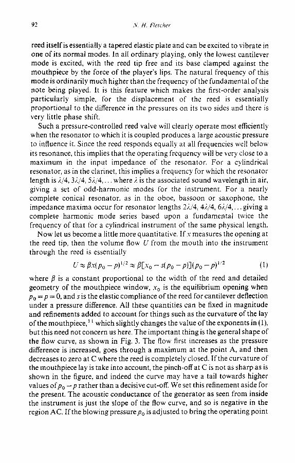
While the conductance characteristic shown in Fig. 3 is linear if the pressure p makes only small excursions around the operating point O, this is clearly no longer true ifp becomes an appreciable fraction ofpo. We can investigate the effect of this nonlinearity semi-quantitatively without much difficulty. With the values of the various parameters in (1) fixed, we assume a small sinusoidal variation in pressure in the mouthpiece of the instrument at a frequency coincident with that of the first impedance maximum of the instrument tube, which we take to be cylindrical as in a clarinet. From eqn (1) this gives a flow U(t) through the reed which we can readily calculate. This flow is periodic and so has a set of harmonic overtones which we may take as being coincident in frequency with the impedance maxima and minima of the pipe-- the odd harmonics lying on the maxima and the even harmonics on the minima. To a reasonable approximation, the impedance at the maxima can be taken as a constant large resistive quantity R, and that at the minima to be zero. The odd harmonics constitute the symmetric part U+ of the flow waveform and the even harmonics the antisymmetric part U_, so that the pressure generated in the instrument tube by the flow is essentially RU+, which can be easily evaluated from the calculated waveform by averaging, with a sign change, flows at phases 4' and ~ + ~z. This pressure is now taken as the starting point for a new calculation of the flow, and the process is repeated. It converges after a few iterations if we make the further refinement of introducing some waveform smoothing to represent the facts that the higher pipe resonances are greatly reduced in amplitude and that the reed responds only below its resonance frequency. The results of such a calculation for the clarinet flow waveform, or equivalently the pressure waveform in the mouthpiece, are shown in Fig. 5, for three different assumed values of the parameter/~ in (1), corresponding to soft, medium and very loud playing.
We see immediately that the nonlinearity limits the maximum excursion of the flow to the difference between the flows at points A and C in Fig. 3, and thus limits the maximum pressure amplitude in the instrument. At lower playing levels, the curvature of the flow characteristic similarly limits the amplitude. The calculated waveform is, of course, exactly symmetrical because of our removal of all even harmonics, a feature which is not exactly preserved in real instruments because of misalignment of the impedance maxima. More importantly, we note that the complexity of the waveform,
96 N. H. Fletcher
CZ?
Time
Fig. 5. Calculated flow waveforms generated by a clarinet-type reed coupled to an ideal cylindrical resonator, for three different levels of playing loudness, increasing from the top.
Pressure waveforms in the mouthpiece are similar.
and thus the harmonic richness of the tone, increases with increasing playing level--a feature of nearly all musical instruments. It is not quite as simple to calculate the waveform of the radiated sound, because there is a change in sign in harmonics 3, 7, 11 . . . . relative to 1, 5, 9 . . . . by the time we reach the open mouth of the air column, and then a radiation characteristic which essentially amounts to a differentiation of the shifted wave. The radiated spectrum, however, ignores the phase shifts and simply adds a rising emphasis of 6 riB/octave up to the cut-off frequency, as noted before.
An approximate treatment of this kind can also be applied to conical woodwinds, such as the oboe or saxophone, by using the complete flow waveform rather than just its symmetric part. While this is simple in principle, the result depends to a much greater extent upon details of the pinch-off behaviour of the reed near point C in Fig. 3 than in the case we have just discussed. Indeed for the simple flow characteristic of eqn (1) the reed is found to close completely once in each cycle if the sound is to be maintained, giving a waveform with sharp corners and a much higher harmonic development than for the clarinet. While such behaviour is to some extent found in the oboe, it is clear--as the oboist knows from experience--that details of reed geometry can cause variations between unplayability or raucous sounds and satisfying tonal beauty.
To explore these phenomena in greater detail we require the more formal

Nonlinear theory o f musical wind instruments 97
techniques of the method of harmonic balance. The principle of this approach has been outlined and applied to the clarinet by Schumacher.t5 We assume that the pressure in the mouthpiece is periodic with a period set for convenience equal to unity, so that
p(t) = pk e'-~kr 13)
k = - ~
The Fourier components Pk of the mouthpiece pressure are related to those of the flow U(t) by
p~ = Zkb ~ (4)
where Z k is the input impedance ofthe resonator tube at frequency k and U~ is given by
U(p,x) e - "~ik' dt (5)
and U(p,x) is given by (1) and (2). Substituting (5) into (3) gives the integral equation
p(t) = [-' K(t - t 'jU(p, x) dr' (6) J0
where the kernel K(t) is given by
K(t)= ) , Zk ez'~ik~ (7)
Schumacher has shown how this equation can be solved by an iteration method.
As we remarked in the introduction, the method of harmonic balance is essentially straightforward in principle, but gives results only for steady- state oscillation. To examine the approach to the steady state, or in other words the initial transient, we must use other approaches.
Nonlinear theory in the frequency domain
First let us look at what we characterised as the frequency-domain approach. The behaviour of the linear air column resonator can be expressed in terms of its pressure eigenfunctions (or normal modes, or standing waves), which we write in the form tp,(y,t) where v is a coordinate measuring distance along the air column from the reed at v = 0. Thfs assumes that the modes are derived from plane waves and have no variation across the bore--
9s .v. H. Fletcher
a reasonable approximation in most cases. To a good approximation ~ / # . v = 0 at l' = 0, but we can modify this boundary condition to allow for the influence of the vocal tract and the reed compliance. We normalise the wave functions so that the.,, all have unit square integrals as usual. The natural frequency of the nth mode is taken to be ~,}.. A little consideration then shows that the equation describing the nth mode when excited by a volume flow U ( t ) i n j e c t e d at v= 0 is
~2ur," ~..~. , (2u? ° ~ U . = v + 2k - c- . = ~z. - -~ O( v - 0) (8) c t - ~t ( 'v 2 "
where c is the velocity of sound and
~L. = ~,~(0) (9)
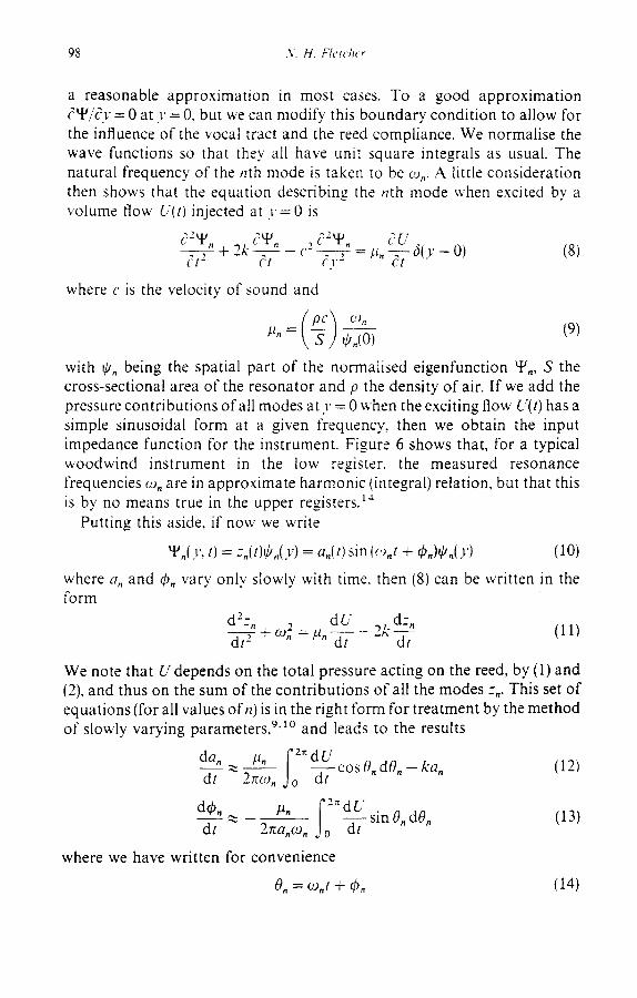
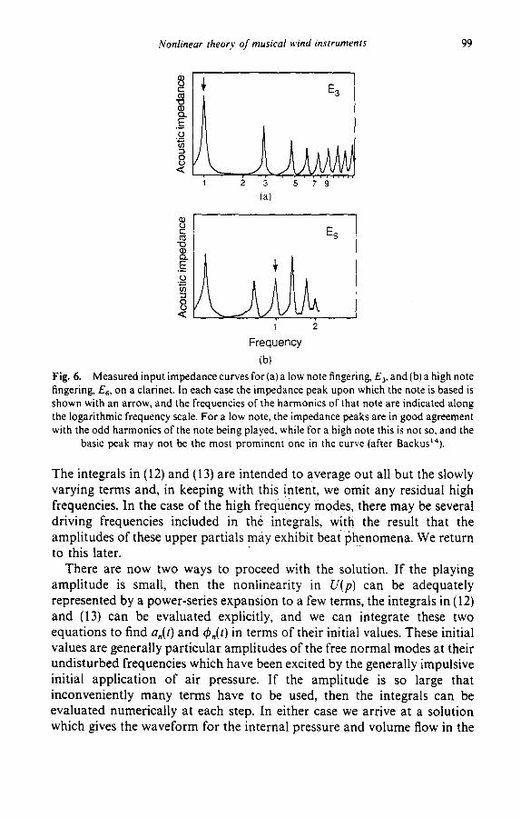
with ~,. being the spatial part of the normalised eigenfunction u-F., S the cross-sectional area of the resonator and p the density of air. If we add the pressure contributions of all modes at y = 0 when the exciting flow U(t) has a simple sinusoidal form at a given frequency, then we obtain the input impedance function for the instrument. Figure 6 shows that, for a typical woodwind instrument in the low register, the measured resonance frequencies co. are in approximate harmonic (integral) relation, but that this is by no means true in the upper registers. ~~
Putting this aside, if now we write
• . ( y , t) = z . ( t ) ~ . ( y ) = a . ( t ) sin (co.t + qS.)~,.()') (10)
where a. and ~b. vary only slowly with time. then (8) can be written in the form
d- - . dU +_co2 =~L. 2 k dz" (11) d t 2 d t d t
We note that U depends on the total pressure acting on the reed, by (1) and (2), and thus on the sum of the contributions of all the modes z.. This set of equations (for all values of n) is in the right form for t reatment by the method of slowly varying parameters, 9'~° and leads to the results
da. ~l. ('2~ dU - - ~ - - I - - c o s O . d O . - k a . (12) dt 2rcco. J0 dt
d~----2 ~ /~" sin O. dO. (13) dt 2~za.co.
where we have written for convenience
0. = co.t + ~, (14)
Nonlinear theory of musical wind instruments 99
8 c"
t~
e 0 4....,
:3
8 \
E3
2 3 5 7 9
(a)
E 6 '13
E
1 2
Frequency (b)
Fig. 6. Measured input impedance curves for (a) a low note fingering, E 3, and (b) a high note fingering, E6, on a clarinet. In each case the impedance peak upon which the note is based is shown with an arrow, and the frequencies of the harmonics of that note are indicated along the logarithmic frequency scale. For a low note, the impedance peaks are in good agreement with the odd harmonics of the note being played, while for a high note this is not so, and the
basic peak may not be the most prominent one in the curve (after Backust'~).
The integrals in (12) and (13) are intended to average out all but the slowly varying terms and, in keeping with this intent, we omit any residual high frequencies. In the case of the high frequency modes, there may be several driving frequencies included in the integrals, with the result that the amplitudes of these upper partial s may exhibit beat phenomena. We return to this later.
There are now two ways to proceed with the solution. If the playing amplitude is small, then the nonlinearity in U(p) can be adequately represented by a power-series expansion to a few terms, the integrals in (12) and (13) can be evaluated explicitly, and we can integrate these two equations to find a.(t) and q~,(t) in terms of their initial values. These initial values are generally particular amplitudes of the free normal modes at their undisturbed frequencies which have been excited by the generally impulsive initial application of air pressure. If the amplitude is so large that inconveniently many terms have to be used, then the integrals can be evaluated numerically at each step. In either case we arrive at a solution which gives the waveform for the internal pressure and volume flow in the

I00 N. H. Fletcher
instrument, including both steady-state and transient phases. This method has not been used to examine transients in clarinet-like systems, but the approach is essentially the same as that used for organ pipes by Fletcher. L6
In the process of this solution we find a very important effect of the nonlinearity. The air column mode frequencies co, are not ever in exact harmonic relation, and may be quite far from this, as illustrated in Fig. 6. The cross-terms contributed by the quadratic and cubic terms in the nonlinearity, however, effectively couple the modes together so that they usually lock into precise integral harmonic ratios, t 7 This is possible because the actual sounding frequency of mode n is not co. but rather
co(n) = co, + d(b, dt (15)
It is this circumstance which gives to ~vind instruments their exactly repetitive harmonic waveforms and hence their usefulness for ordinary musical performance. It is only in the case of air column resonances that are very far from integral relationship that this coupling breaks down, giving the peculiar 'multiphonic' tones now being exploited by contemporary composers.
Even without proceeding to an explicit solution, we can examine some aspects of the behaviour from the general form of eqns (12) and (13). For example (12) determines the steady state amplitude when the left-hand side vanishes and the driving term, represented by the integral on the right-hand side, is equal to the damping term ka. Similarly the steady-state frequency shift away from the mode frequency is given by the integral on the right of (13). Because of the complementary nature of the integrals, involving respectively a sine and a cosine term with argument 0, an increase in one involves a decrease in the other. This is simply the resonance phenomenon for the pipe modes driven by the harmonics of the generator frequency. The lower modes naturally lock onto whichever harmonic is closest to their natural frequency, but upper modes may be nearly equally excited by two or more harmonics, giving beat phenomena in which the amplitude and phase of the mode each vary with a frequency equal to the harmonic separation, which is still a 'slow' variation relative to the natural mode frequency. In this way, all the upper harmonics of the generator frequency can be represented in the acoustic spectrum, even though their number may be greater than the number of modes in the same frequency range, as for example in the case of a cylindrical pipe.
Nonlinear theory in the time domain
The solution in the frequency domain, outlined above, has a counterpart in the time domain which is simpler in concept though usually more difficult in
Nonlinear theory of musical wind instruments 101
application to wind instruments. 8"~s Description of the motion of the reed and of flow through it is relatively simple in the time domain, since this description is given by the eqns ( 1 ) and (2) which are formulated in terms of the time-domain functions p(t) and U(t). To treat the air-column resonator in the time domain we need to know its impulse response, or Green function, G ( t - t ' ) which describes the pressure response at time t when a sharp impulsive flow is injected at time t'. If the injected flow has the more general form U(t') , then the pressure response is
p(t) = G ( t - t ' ) U ( t ' ) d t ' (16)
The difficulty arises from the fact that, since G is defined with the mouthpiece end of the air column rigidly closed except at the instant t = t', so that U will be zero, the pressure pulse produced by the impulse is reflected back and forth between the open and closed ends of the tube for a very considerable time. Stated in another way, the impulse response is actually just the Fourier transform of the input impedance, and if the impedance function has sharp peaks in the frequency domain, then its transform has a large extent in the time domain. The convolution integral (16) is therefore very extended and laborious to evaluate.
Schumacher is has suggested a way out of this dilemma, in the case of a cylindrical horn, by recognising that there are initially no reflections when a flow pulse is injected into the air column, and the initial pressure response is just that due to the characteristic impedance Z o of the air column at its input. This suggests writing
G( t - t') = Z o d ( t - t') + G ' ( t - t') (17)
and he shows that G' is related to the Fourier transform of the reflection coefficient r(co) at the mouthpiece end of the horn. Thus
r(co) = [Z~(co) - Zo] /EZ~(e , ) + Zo] (18)
where Z~ is the input impedance at the horn throat, and its transform r(t) is the impulse response when the horn input is blocked with a non-reflecting termination after the initial pulse is injected. In general r ( t - t') will have a much shorter time span than G(t - t'), though it may still be complicated by multiple reflections from finger holes and other irregularities in the bore. In terms of this reflection coefficient, Schumacher shows that the pressure response is given by
p( t ) = Z o U ( t ) + f o r ( t ' ) [ Z ° U ( t - t') + p ( t - t')] dt' (19)
Equation (19) is in a simple form for numerical integration if the form of

I02 N. H. Fletcher
r(t) is known and the initial conditions for U and p are specified. Unfortunately r is still a complicated function of time with a considerable duration for real musical instruments of the woodwind family. The general behaviour is clear, however, for the case of a narrow cylindrical pipe, for which reflection from the open end simply returns an inverted and delayed pulse, so that r(t) has the form
r( t) ~ - - A 6 ( t - - z) ( 2 0 )
Here A is a constant, slightly less than unity, which represents the effects of wall losses as the pulse travels along the tube, 6 ( t - t ' ) is a Dirac delta function, and r is the pulse travel time from the mouthpiece to the open end and back. In a more refined treatment the form ofr(t)can be modified so that it returns a slightly broadened pulse. Substitution of (20)into (19) and its once-repeated form requires that
p ( t ) = - - A p ( t - - r) + Z o [ U ( t ) - U ( t - r)] (2t)
p ( t ) = A Z p ( t - - 2r) + Z o [ U ( t ) - 2AU(t - r) + A Z U ( t - 2r)] (22)
Taken together, and recognising that for a reed generator p >> Z0 U, these equations imply that the pressure waveform repeats with period 2r and has almost no energy in its even harmonics. The terms in U serve to maintain the waveform in (22) against the fact that A is slightly less than unity, and do not exactly balance out the even harmonics in (21). The actual waveform p ( t ) i s
determined by the reed flow characteristic in (i) and (2) in conjunction with (21) and (22), or more realistically in (19).
This same approach can be used for instruments with noncylindrical horns, but is then complicated by the fact that the characteristic impedance at the horn input is no longer the simple quantity Zo = p c / S but a more complex function. The theory for the case of conical horns has been explored by Martinez e ta / . , 19 '2° and turns out to involve complicated divergences when there are changes in horn profile, making the analysis difficult in the general case. For a simple conical horn with a very small truncation at the mouthpiece end, detailed consideration shows that the wave period is not 2r but rather r. This accounts for the presence of even as well as odd harmonics in the spectrum of conical instruments such as the oboe and saxophone.
LIP G E N E R A T O R S
Linear theory
There are important similarities between the behaviour of lip-driven instruments of the brass family, the generator mechanism of which is shown

Nonlinear theory of musical wind instruments 103
Fig. 7. The mouthpiece of lip-reed instrument such as the trumpet. The player's lips are forced open by the blowing pressure in the mouth. The mouthpiece cup and constriction form a Helmholtz resonator which assists tone production by modifying the input impedance
curve of the instrument.
in Fig. 7, and reed-driven instruments of the woodwind family. There are also important differences which arise from the fact that the blowing pressure tends to force the player's lips open, while in woodwinds it tends to force the reed closed. This appears as a change in the sign o f s in eqn (1) and of(Po - p ) on the right-hand side ofeqn (2) above. This has the consequence that the static flow characteristic U(po -p) simply rises with (Po - P ) and has no negative-resistance region. The form of the acoustic conductance at non- zero frequency ~2 is similarly inverted compared with the reed case shown
in Fig. 4, and now has the shape shown in Fig. 8. The region of negative
l
Frequency co
Fig, 8. The small-signal acoustic conductance (real part of the admittance) as a function of frequency e) for a lip-reed generator of the trumpet type, with resonance frequency e) r. The mechanism acts as an acoustic generator for only a small frequency range just above the
resonance frequency.

104 .Y. H. F/erclwr
conductance associated with operation as an acoustic generator is limited to a narrow frequency range just above the resonance frequency of the mechanical vibration of the lips. If the static opening .% of the lips in the absence of blowing pressure is zero, as is generally the case, then there is no threshold blowing pressure required for generator action (though if .v o > 0 there is a threshold just as for the blown-closed reed).
The consequences of this behaviour are immediate. Clearly the player must adjust the lip resonance frequency to coincide quite closely with the frequency of the note to be played, and this frequency must also be very close to an impedance maximum of the instrument air column, or rather of the instrument in series with the player's vocal tract, in order that an adequate mouthpiece pressure can be built up to control the reed. Balance between the reactive parts of the lip and instrument impedances will control the exact sounding frequency. The lip resonance can fortunately be made very narrow, so that notes lying only a semitone apart, and represented by adjacent resonances in the upper register of an instrument such as the French horn, can be selected with good reliability by a skilled player.
The input impedance of a typical brass instrument is determined by the length and profile of the horn itself and by the Helmholtz resonance of the cavity and back-bore of the mouthpiece cup.-' ~ This is illustrated in Fig, 9, which shows the calculated effect of coupling a trumpet-like mouthpiece to a long cylindrical tube. The Helmholtz resonance of the mouthpiece, loaded by the characteristic impedance of the horn, raises the level of impedance maxima in the playing range of the instrument and thus helps tone production, as well as providing a comfortable support for the player's lips.
8 e-
E
8 ,< k_ Frequency
Fig. 9. Calculated input impedance of a cylindrical tube fitted with a brass-instrument mouthpiece. The Helm holtz resonance of the mouthpiece raises the levels of impedance peaks in the playing range. The addition of a flaring bell to the instrument adjusts the frequencies of the resonances so that, with the exception of the first resonance, they have nearly harmonic
frequency ratios 2, 3, 4 .....

Nonlinear theory of musical wind instruments 105
The exact frequencies of the horn resonances depend upon the flare at its bell end and are generally adjusted to produce a fairly accurate integer-harmonic series, though with the first-mode resonance unavoidably very much below its nominal frequency. The player selects any one of these resonances as the fundamental of the note to be played, and intermediate notes can be produced by shifting the whole frequency scale downwards by adding lengths of tube at the mouthpiece end of the instrument using valves or a slide.
There is an interesting feature of brass instrument performance which arises from the considerable length of the horn--several metres in a typical case. The travel time for the first pulse of a note to propagate from the player's lips to the open end of the bell and then reflect back to the lips may be many periods of the lip vibration when a high note is being played. The player must thus adjust lip and vocal-tract resonances to produce a self- sustaining vibration during this time, and a characteristic attack transient will evolve.
Once again, the radiated power, frequency spectrum and transient behaviour of the instrument are all dominated by nonlinear effects, and these can be treated either in the frequency domain or in the time domain. The formal development is identical with that outlined above for reed-driven instruments, so that all that is required is a set of comments on the results.
Nonlinear behaviour in the harmonic-balance approximation
Description of the behaviour of the instrument mouthpiece and horn, together with the player's vocal tract, is relatively simple in the frequency domain, as we have outlined above. The behaviour of the player's lips is described by a driven harmonic oscillator eqn (2), as for a reed but with the sign of the driving term reversed. The resulting motion is now much simpler, however, since the driving pressure is close to the reed resonance, giving large amplitude, while all harmonics are well above this resonance frequency and produce very little disturbance to the motion. This has been verified by stroboscopic study, 22 the lips being found typically to just close once in each cycle in normal playing. With the lip motion x(t)= a(1 + sin e~t)determined in frequency and form, though not in amplitude a, it is now simple to write down the flow U(t) in terms of the pressure difference (Po-P) , using the modified form of eqns (1) and (2) appropriate for a lip generator. The flow U(t) can be decomposed into harmonic frequency components, each of which lies close to an impedance maximum in a well designed instrument.-' t The analysis then proceeds as outlined for the reed case.
We can simplify the analysis greatly, however, and obtain some immediate insight, by an approximate treatment. If we take the instrument resonances

106 N. H. Fletcher
to be precisely aligned, then the impedance met by each harmonic of the generator flow is a nearly purely resistance R. F rom Fig. 9 we can also assume as an approximat ion that R is nearly the same tbr the first few harmonics. F rom (1) this leads to an equat ion of the form
p ~ R U ~ - - - - - ~ 1 + (R-~)2_ ] - 1 (23)
where/3 is the constant in t roduced in (1), which is propor t ional to the width of the opening in the lips when their shape and tension have been adjusted to achieve the required resonance frequency co. This is a simplified form of the harmonic-balance t reatment developed by Backus & Hundley 23 for the trumpet .
If the lip configuration and blowing pressure are adjusted so that the lip vibration ampli tude a is small, which goes along with a small value of fl, so that fla<<2p~/2/R as would be appropr ia te in quiet playing, then the approximate solution to (23) is
p ~, Rflp~/2x ~ Rflp~/Za(1 + sin ~ot) (24)
Thus, at this low playing level, the acoustic pressure is nearly sinusoidal. Since the lip vibration ampl i tude a increases with increasingpo, the acoustic pressure p in the mouthpiece rises more rapidly with blowing pressure than suggested by the form of this equation. Indeed, if the lip tension is maintained constant, then we should expect the average value a of the lip opening to be propor t ional to the blowing pressure, so that p should vary as
P0
O.-
e--
0 5 Normalised lip opening (R#/Po,/2)x
Fig. 10. Approximate dynamic relationship between lip opening x and mouthpiece acoustic pressure p for a lip-driven brass instrument. The lip opening varies sinusoidally between 0 and
2a about its mean value a.

Nonlinear theory of musical wind instruments 107
about the 3/2 power of the blowing pressure. In loud playing, on the other hand, the width of the lip opening and the lip vibrat ion ampli tude are both large, so that the approximat ion leading to (24) is no longer valid and we must use the full form (23).
The shape of this waveform, for a range of cases including the low-level approximat ion (24), can be deduced by plott ing the curve given by (23), as shown in Fig. 10. The average lip opening is centred on the line marked a, and the opening x itself has a sinusoidal excursion between 0 and 2a. The mouthp iece pressure waveform p(t) will clearly be dis tor ted in an asymmetrical manner . Calculated results are as shown in Fig. 11, and the large-ampli tude waveform is very similar to that actually observed for a t rombone playing loudly. 24 The waveform is clearly nonsinusoidal and contains overtones of significant amplitude, though they are not as marked as in the case of a reed instrument.
It is impor tan t to emphasise, however, that this t reatment is only a first approximat ion. To obtain a reasonably accurate waveform we must clearly take into account the detailed resonance properties of the ins t rument mouthpiece and horn, as exhibited in the complex input impedance curve. We can then proceed to carry out the calculation in the manner outl ined for the case of reed instruments.
It is possible that, for very loud playing, the lips may close for an appreciable part of each oscillatory cycle. If this happens, the simple
Time Fig. 11. Calculated flow or pressure waveforms for a lip-generator coupled to an ideal brass-instrument horn with harmonic resonances, for three different levels of playing
loudness, increasing from the top.
108 N.H. Fletcher
treatment given above is no longer applicable, for the pressure oscillations in the horn while the lips are closed are no longer described by the simple approximation p ~ RU. In this case, which yields an even greater harmonic development in the tone, we must go to a more careful treatment.
Nonlinear behaviour in the time domain
An instrument of the brass family is in many ways more suitable for treatment in the time domain than is a woodwind instrument, since the smooth bore of the horn produces mostly a reflection associated with the sharp flare and open end of the bell. The large time delay between initiation of a sound by the lips and its reinforcement by waves reflected from the open bell also makes the time-domain treatment particularly appropriate. The nature of this bell reflection is quite complicated, but combines with the complex propagation behaviour of the horn to give a simple shape to the reflected pulse. This corresponds, in the frequency domain, to the adjustment of mode frequencies accomplished by the bell.
The form of the analysis is very similar to that for a woodwind instrument, except that explicit note must be taken of the autonomous nature of the lip vibration. Clearly the time-domain approach gives a very direct description of the initial transient, since the integral in (19)is zero until the first part of the pulse returns from the bell, and during this time the mouthpiece pressure is simply Zo U(t) where Z 0 is the characteristic impedance of the horn at its input, modified by the Helmholtz resonance effect of the mouthpiece. No detailed discussion of waveforms for brass instruments calculated in this way has been published, to our knowledge, but it is not expected that it would lead to any surprises.
Frequency-domain analysis
The treatment given by the harmonic-balance approach clearly applies only to the steady state. To derive a more accurate waveform and amplitude we must solve the pressure and flow equations in the frequency domain properly, as was indicated for reed instruments. The process is conceptually simple, but has a large algebraic and computational load i fmore than a few resonator modes are considered. This treatment will give, however, the form of the initial transient as well as that of the steady state.
In relation to the attack transient, upon the nature of which we remarked when discussing reed instruments, it is interesting to observe that the initial pulse propagation is in fact properly described by the frequency-domain analysis. The initial conditions for the nonlinear mode-growth equations (12) and (13) are those appropriate to injection of a pulse of airflow at the

Nonlinear theory of musical wind instruments 109
mouthpiece of tl~e instrument. This excites all the normal modes at their natural frequencies and in phase at the mouthpiece. Such a state is, however, just the frequency-domain representation of a step-function located at the mouthpiece as origin, with zero amplitude elsewhere in the horn. The time- evolution of the mode amplitudes and phases, as described by (12) and (13), translates into the time domain as a propagation of the step-pulse along the horn, followed by a reflection from the open bell. It takes about one period of the lowest mode of the horn for eqn (12) to reduce its amplitude by a factor e if it is not the mode supported by the lip excitation, and this defines the length of the attack transient, all the other modes having adjusted to their steady state amplitudes and locked together in frequency in about the same time.
AIR-JET GENERATORS
Linear theory
To complete this survey of wind instruments, we must look at those of the flute family, which are excited by an air jet blown across an aperture and impinging on a lip at the opposite side. Such a mechanism relies upon the deflection of the jet by acoustic flow at the aperture and is therefore described as a flow-controlled generator, to distinguish from the pressure- controlled reed and lip generators. A flow-controlled generator is efficient only near a maximum in the acoustic velocity of the resonator to which it is coupled, and the operating frequency is therefore close to a minimum in the input impedance, or equivalently to a maximum in the admittance.
The linear theory of such an air-jet generator is essentially more complex than that of a reed generator, since it must describe the generation and propagation of disturbances along the jet. These are of two basic forms, 'varicose', in which the thickness of the jet varies, and 'sinuous', in which the jet direction is modified. Varicose disturbances find application in cavity whistles in which the jet passes successively through two apertures, 26 and are not used in conventional musical instruments, all of which rely upon transverse sinuous displacement of a more-or-less sheet-like jet as shown in Fig. 12. The jet is always coupled to an air-column or air-cavity resonator in musical instruments, though it is possible to produce weak "edge-tones' from jets impinging on isolated obstacles.
When a plane jet (either laminar or turbulent) emerges from a slit into a transverse acoustic flow field, it is deflected as shown in Fig. 12 and this deflection propagates along the jet with a phase velocity equal to about half the jet velocity. The amplitude of the disturbance grows, provided that its wavelength is greater than about five times the jet thickness; for shorter
1 I0 .V.H. Fletcher
. . . . . . . . . . . . . : : ; :
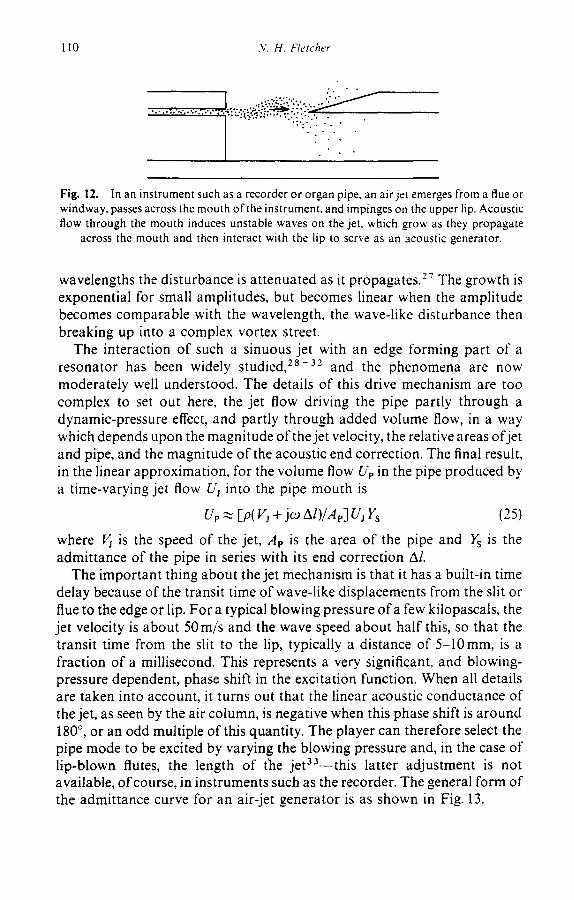
Fig. 12. In an instrument such as a recorder or organ pipe, an air jet emerges from a flue or windway, passes across the mouth of the instrument, and impinges on the upper lip. Acoustic flow through the mouth induces unstable waves on the jet, which grow as they propagate
across the mouth and then interact with the lip to serve as an acoustic generator.
wavelengths the disturbance is attenuated as it propagates.-'; The growth is exponential for small amplitudes, but becomes linear when the amplitude becomes comparable with the wavelength, the wave-like disturbance then breaking up into a complex vortex street.
The interaction of such a sinuous jet with an edge forming part of a resonator has been widely studied, 2s-32 and the phenomena are now moderately well understood. The details of this drive mechanism are too complex to set out here, the jet flow driving the pipe partly through a dynamic-pressure effect, and partly through added volume flow, in a way which depends upon the magnitude of the jet velocity, the relative areas of jet and pipe, and the magnitude of the acoustic end correction. The final result, in the linear approximation, for the volume flow Up in the pipe produced by a time-varying jet flow Uj into the pipe mouth is
Ue ~ [p( Vj + j~o Al)/Ap] U~ Ys (25)
where Vj is the speed of the jet, Ae is the area of the pipe and Ys is the admittance of the pipe in series with its end correction A/.
The important thing about the jet mechanism is that it has a built-in time delay because of the transit time of wave-like displacements from the slit or flue to the edge or lip. For a typical blowing pressure of a few kilopascals, the jet velocity is about 50 m/s and the wave speed about half this, so that the transit time from the slit to the lip, typically a distance of 5-10mm, is a fraction of a millisecond. This represents a very significant, and blowing- pressure dependent, phase shift in the excitation function. When all details are taken into account, it turns out that the linear acoustic conductance of the jet, as seen by the air column, is negative when this phase shift is around 180 °, or an odd multiple of this quantity. The player can therefore select the pipe mode to be excited by varying the blowing pressure and, in the case of lip-blown flutes, the length of the jet33--this latter adjustment is not available, of course, in instruments such as the recorder. The general form of the admittance curve for an air-jet generator is as shown in Fig. 13.

Nonlinear theory o f musical wind instruments I I 1
f
\ L/ Re( ~" )
Fig. 13. The complex acoustic admittance Y of an air-jet generator has a spiral form, either when plotted as a function of frequency for a given blowing pressure, or when plotted as a function of blowing pressure for a fixed frequency, though details of the curves are not identical. The air jet acts as an acoustic generator when the admittance lies in the left half of the complex plane, which corresponds to a phase shift of between about t2n + 1/2)n and
(2n + 3/2)zr for wave propagation along the jet.
Nonlinear behaviour
The essence of the driving force is the volume flow of the jet into the pipe, which for larger amplitudes has a form like that shown in Fig. 14, saturating both when the flow is completely into the pipe and when it is completely outside the pipe. Detailed consideration shows that the shape of this curve is fairly closely a hyperbolic tangent function, 2v though any similarly shaped curve could be assumed. The driving force is linear for small excursions about the operating point O, but departs rather gently from linearity for larger amplitudes.
We can use the same techniques outlined above to treat the nonlinear sound production mechanism in air-jet driven instruments. We shall not go into this in detail, but rather just look at the first approximation. To do this we first note that, with the jet length and blowing pressure optimally adjusted for a particular mode, the phase shift for the nth harmonic of this mode is approximately n n . This means that odd harmonics will behave rather differently from even harmonics, but in most cases the second harmonic will not be reinforced by the jet-drive mechanism. Indeed the attenuation behaviour of the jet for short wavelengths generally means that there is very little'driving force for any of the higher harmonics. This statement is an oversimplification, of course, since the jet has a negative conductance over a considerable frequency range, or equivalently a considerable pressure range, about its optimal condition, but it will suffice for our first approximation. We thus assume that the feedback mechanism

112 N. H. Fletcher
T t
o
c
o
Jet deflection
Fig. 14. The flow U of a jet into the mouth of a pipe at the upper lip has a hyperbolic tangent form as a function of the jet deflection. The sharp edge of the lip is generally offset to a point 0
a distance .% from the centre-plane C of the jet.
reinforces the fundamental only, so that only this mode propagates on the jet and higher harmonics are produced by the inherent nonlinearity in the drive mechanism.
Detailed consideration of this situation 3-~ shows that the relative strength of the harmonics is strongly influenced by the extent to which the pipe lip is offset relative to the centre-plane of the jet. Such an offset moves the operating point O of Fig. 14 away from the symmetry plane C, and the result then follows from expansion of the flow function
U(t) = (Uo/2){ 1 + tanh[xo + a sin (cot)] } (26)
where x o defines the operating-point offset from the centre-plane C of the jet and a is the amplitude of the jet displacement at the lip, measured in units of the jet half-width. The amplitudes of the upper harmonics produced by the driving function increase with increasing jet deflection amplitude, and their relative strengths vary with jet offset as shown in Fig. 15. To convert this driving function to response of the resonator we need to multiply by the terminated resonator admittance at each frequency, as given by (25). In most flute-like instruments the resonances are well aligned, so that we can take the conductive part of the pipe admittance to be roughly constant, as we did for the impedance of the trumpet, and the resonator spectrum then parallels that of the drive function. An exception occurs, of course, for a stopped organ pipe, for which the admittance is high only for odd harmonics. In many flute-like instruments the upper partials are well developed, though the 'softness' of the nonlinearity in Fig. 13 means that they are much less fully developed than in reed or lip-driven instruments.
Transient effects can be examined essentially as outlined before for the

Nonlinear theory of musical wind instruments II 3
I
"O
>
>
(b -60
-3 -2 -1 1 2
Jet offset x o
Fig. 15. The relative levels ofthe harmonics generated by a jet interacting with an ideal open cylindrical pipe are influenced by the offset .,c o of the upper lip of the pipe away from the centre-plane of the jet. This quantity is shown measured in units of the half-width of the jet.
The levels of successive harmonics have been offset by 10dB for clarity.
frequency-domain treatment, ~6 but in a dual way, in the sense that flows replace pressures and admittances replace impedances. Initial transients in jet-driven instruments typically occupy 20-40 periods of the fundamental of the note being played.
Finally we note that nonlinear effects are very important in air-jet instruments in controll ing the transition from one pipe mode to another. 33'35 The exact value of the blowing pressure relative to that required to make a transition to the next higher mode also has a significant effect on the relative intensities of the two modes concerned.
CONCLUSION
This review has only sketched the important role played by nonlinearity in determining the sound output of musical wind instruments, and shows in outline how one may reach a quantitative understanding of the steady waveforms and transient effects that are so important in giving each instrument its characteristic auditory effect.
Concentrating on nonlinearity, it has not been the intention to belittle the
114 N. H. Fletcher
role of linear effects or of linear theory in determining and describing instrument behaviour-- indeed, since nonlinearity is always with us. do what we may, and it is not unreasonable to take the approach of looking after linear effects in instrument design and leaving nonlinearities to take care of themselves! Be that as it may, it is the nonlinearities, as this paper has tried to show, which win in the end.
R E F E R E N C E S
1. Carse, A., ,I, Iusical Windlnstruments. Macmillan, London, 1939 and Da Capo, New York, 1965.
2. Kent, E. L., Musical Acoustics: Piano attd Wind btstruments. Dowden, Hutchinson & Ross, Stroudsburg, PA, 1977.
3. Fletcher, N. H., Air flow and sound generation in musical wind instruments. Annual Ret'iew o['Fluid Mechanics, 11 (1979) 123-46.
4. Nederveen, C. J., Acoustical Aspects O/" Woodwind Instruments. Frits Knuf, Amsterdam, 1969.
*5. Benade, A. H. & Gans, D. J., Sound production in wind instruments. Annals of the New York Academy of Science, 155 (1968) 247-63.
6. Benade, A. H., Fundamentals of Musical Acoustics. Oxford University Press, New York, 1976.
*7. Benade, A. H., On the mathematical theory of woodwind finger holes. Journal of the Acoustical Socieo" of America, 32 (1960) 1591-608.
8. McIntyre, M. E., Schumacher, R. T. & Woodhouse, J., On the oscillation of musical instruments. Journal of the Acoustical Socieo' of America, 74 (1983) 1325-45.
9. Bogoliubov, N. N. & Mitropolsky, Y. A., Ao'mptotic Methods in the Theory of Nonlinear Oscillations. Hindustan, New Delhi and Gordon and Breach, New York, 1961.
10. Mickens, R. E., An Introduction to Nonlinear Oscillations, Chapter3. Cambridge University Press, Cambridge, 1981.
* 11. Backus, J., Small-vibration theory of the clarinet. Journal of the Acoustical Socie O' of America, 35 (1963) 305-13.
12. Fletcher, N. H., Excitation mechanisms in woodwind and brass instruments. Acustica, 43 (1979) 63-72.
13. Thompson, S. C., The effect of the reed resonance on woodwind tone production. Journal of the Acoustical SocieO' of America, 66 (I 979) 1299-307.
14. Backus, J., Input impedance curves for the reed woodwind instruments. Journal of the Acoustical Society of America, 56 (1974) 1266-79.
15. Schumacher, R. T., Self-sustained oscillations of the clarinet: An integral equation approach. Acustica, 40 (1978) 298-309.
t6. Fletcher, N. H., Transients in the speech of organ flue pipes--a theoretical study. Acustica, 34 (1976) 224-33.
17. Fletcher, N. H., Mode locking in nonlinearly excited inharmonic musical oscillators. Journal of the Acoustical Society of America, 64 (1978) 1566-9.
* Papers marked with an asterisk are included in the reprint collection edited by Kent.-'
Nonlinear theory of musical wind instruments I15
18. Schumacher, R. T., Ab initio calculations of the oscillations of a clarinet. Acustica, 48 (1981) 71-85.
19. Martinez, J. & Agullo, J., Conical bores. Part I: Reflection functions associated with discontinuities. Journal of the Acoustical Society of America, 84 (1988) 1613-19.
20. Martinez, J., Agull6, J. & Cardona, S., Conical bores. Part lI: Multiconvo- lution. Journal of the Acoustical Society of America, 84 (1988) 1620--7.
"21. Benade, A. H., The physics of brasses. Scientific American, 229(1)(1973) 24-35, *22. Martin, D. W., Lip vibrations in a cornet mouthpiece. Journal O['the Acoustical
Society of America, 13 (1942) 305-8. 23. Backus, J. & Hundley, T. C., Harmonic generation in the trumpet. Journal of
the Acoustical Soc&ty of America, 49 (1971) 509-19. 24. Elliott, S. J. & Bowsher, J. M., Regeneration in brass wind instruments. Journal
of Sound and Vibration, 83 (1982)181-217. *25. Benade, A. H. & Jansson, E. V., On plane and spherical waves in horns with
nonuniform flare. Acustica, 31 (1974) 80-98. 26. Chanaud, R. C., Aerodynamic whistles. Scientific American, 222(I)(1970) 40-6. 27. Thwaites, S. & Fletcher, N. H., Wave propagation on turbulent jets. Acustica,
45 (1980) 175-9; 51 (1982) 44-9. 28. Cremer, L. & lsing, H., Die selbsterregten Schwingungen von Orgelpfeifen.
Acustica, 19 (1967) 143-53. *29. Coltman, J. W., Sounding mechanism of the flute and organ pipe. Journal ~]'the
Acoustical Societ.v of America, 44 (1968) 983-92. 30. Elder, S. A., On the mechanism of sound production in organ pipes. Jo,o'nal of
the Acoustical Society of America, 54 ( 1973) 1554-64. 31. Fletcher, N. H., Jet-drive mechanism in organ pipes. Journal of the Acoustical
Society of America, 60 (1976) 48 I-3. 32. Thwaites, S. & Fletcher, N. H., Acoustic admittance of organ pipe jets. Jo,o'nal
of the Acoustical Society of America, 74 (1983) 400-8. *33. Fletcher, N. H., Acoustical correlates of flute performance technique. Jo,rnal
of the Acoustical Society of America, 57 (1975) 233-7. 34. Fletcher, N. H. & Douglas, L. M., Harmonic generation in organ pipes,
recorders and flutes. Journal of the Acoustical Society of America, 68 (1980) 767-71.
*35. Fletcher, N. H., Nonlinear interactions in organ flue pipes. Journal of the Acoustical Society of America, 56 (1974) 645-52.