Embed Size (px)
Citation preview

NASA Technical Memorandum 101546
Nonlinear Shell Analyses of the Space Shuttle Solid Rocket Boosters
(BASA-Td- 101546) B C N L I Y E A B LTLELLI. ALIALYSES C f PEE $&ACE: Z X r i 1 L E SC1II) b C C K E l EOOSTEGS
( b A S A ) 26 F CSCL 20K
189-1 1260
Unclas G3/39 0197209
KI. F. Knight, Jr., R. E. Gillian, and M. P. Nemeth
Januasy 1989
National Aeronautics and Space Administration
Langley Research Center tiampton, Virginia 23665-5225
https://ntrs.nasa.gov/search.jsp?R=19890011889 2018-08-29T08:14:14+00:00Z

Nonlinear Shell Analysis of the Space Shuttle Solid Rocket Boosters
N. F. KNIGHT, JR.t, R. E. GILLIANt, and M. P. NEMETHt
NASA Langley Research Center, Hampton, Virginia 23665-5225, USA
Abstract A variety of structural analyses have been performed on the Solid Rocket Boosters (SRB’s) to provide information that would contribute to the understanding of the fail- ure which destroyed the Space Shuttle Challenger. This paper describes nonlinear shell analyses that were performed to characterize the behavior of an overall SRB structure ,and a segment of the SRB in the vicinity of the External Tank Attachment (ETA) ring. ;Shell finite element models were used that would accurately reflect the global load trans- fer in an SRB in a manner such that nonlinear shell collapse and ovalization could be iusessed. The purpose of these analyses was to calculate the overall dcflection and stress distributions for these SRB models when subjected to mechanical loads corresponding to critical times during the launch sequence. Static analyses of these SRB models were performed using a “snapshot picture” of the loads. Analytical results obtained using these models show no evidence of nonlinear shell collapse for the pre-liftoff loading cases considered.
Introduction The basic elements of the Space Shuttle system are the Orbiter, the External Tank (ET), itnd the two re-usable Solid Rocket Boosters (SRB’s) as shown in figure 1. The SRB’s provide the primary Shuttle ascent boost for the first two minutes of flight with an itssist from the three Space Shuttle Main Engines (SSME’s) on the Orbiter. The SRB Eitructural subsystems include the Solid Rocket Motor (SRM) which consists of four lined, insulated rocket motor segments. These segments ate connected using pinned tang-clevis joints (see figure 2). The upper end of the lower cylindrical, motor segment forms the clevis. The lower end of the upper cylindrical, motor segment forms the tang which mates with the lower clevis. Around the circumference of both tang and clevis ends are 180 holes into which one-inch-diameter connecting pins are inserted and are held in place by retainer bands. The seal between two motor segments is provided by two O-rings in the “inner arm” of the clevis. The O-rings are compressed upon assembly of the SRM segments by a flat sealing surface on the tang.
The accident which destroyed the Space Shuttle Challenger is believed to have been caused by the failure of a case joint in the right solid rocket motor.’ Several characteris- tics of the original SRM joint design have been identified as potential contributors to the failure. One characteristic is the behavior of the joint under internal pressure load. For this loading, the motor case expands radially outward. Because the joint has a higher hoop stiffness than the case wall on either side of the joint, its radial expansion is less than that of the case wall. In addition to this nonuniform stiffness in the longitudinal
t Aerospace Engineers, Structural Mcchanics Branch, Structural Mechanics Division. $ Mathematician, Structural Mechanics Branch, Structural Mechanics Division.
1
direction associated with the case joints, a nonuniform stiffness in the circumferential direction exists in the aft attachment segment due to the external tank attachment (ETA) ring. Nonuniform radial expansion is the primary cause of relative motion be- tween the inner clevis arm and the sealing surface on the tang. This relative motion can cause the O-rings to become unseated and therefore lose their sealing capability.
Structural analyses at various levels of detail have been performed in support of the SRB structural design assessment and redesign efforts. These levels vary from local three-dimensional solid models of a one-degree segment of the tang-clevis joint reported in reference 2 to global models of the SRB reported in references 3 through 5. Axisymmetric shell-of-revolution and axisymmetric solid models of the local joint have been analyzed wherein the overall shell response characteristics are represented well. However, the use of these models to determine the structural response locally in the joint requires substantial engineering judgement due to inherent asymmetries associated with the pins, friction, and contact. In reference 2, the three-dimensional solid finite element models of a one-degree segment (centerline of a pin to midway between pins) of the field joint were used to determine the local joint response to pressure loading including the induced axial load. In reference 3, a linear analysis of the entire SRB, including the propellant, was performed with the MSC/NASTRAN finite element computer code6 using solid elements throughout the model. As such, the local joint behavior could be assessed and data then used in more detailed, local joint models. In reference 4, nonlinear analyses of the entire SRB were performed using shell elements (see figure 3) wherein equivalent stiffness joint models were used, and as such this model cannot predict the local joint behavior. In reference 5, nonlinear analyses of the SRB/ETA ring interface region were performed using a shell finite element model also (see figure 4). These two-dimensional shell models of the SRB have been developed using the STAGSC- 1 computer code7l8. These 2-D shell models have been used to calculate the overall deflection distributions for the SRB when subjected to mechanical loads corresponding to selected times during the launch sequence. The mechanical loading conditions for the full SRB arise from the ET attachment points, the SRM pressure load, and the SRB aft skirt hold down posts. Static analyses of the full SRB were performed using a “snapshot picture” of the loads. The purpose of this paper is to provide a summary of the nonlinear analyses performed in references 4 and 5 including a description of the computational approach and requirements, and a presentation of results from the analyses of the Space Shuttle solid rocket boosters subjected to selected pre-liftoff loads corresponding to Space Transportation System (STS) Flight 51-L.
Method of Analysis The STAGSC-1 computer code’s8 has been under development for over 15 years and its development was initiated to support the design and analysis of the space shuttle system. STAGSC-1 is a 2-D shell finite element analysis code based on the displacement formulation. The element library includes nonlinear spring (or mount) elements, 1-D beam elements, and 2-D plate/shell elements. Analysis options are provided for includ- ing geometric and material nonlinearities for buckling, collapse, vibration, or transient dynamic analysis. STAGSC-1 is supported on CDC, VAX, and Cray computers and is available through COSMICt.
The STAGSC-1 computer code is comprised of six modules: STAGS1; STAGS2;
t COSMIC is a non-profit agency, established by NASA as the one central office to collect, evaluate, and distribute software that is developed with NASA funding. COSMIC, The University of Georgia, 382 East Broad Street, Athens, GA 30602, USA.
2

TJNFFMT; FMTUNF; POSTP; and STAPL. The STAGS1 module is a preprocess- ing module which handles model generation, degree-of-freedom tables, element shape functions, element constitutive matrices, and so forth. Execution of this module typi- cally precedes the execution of STAGS2, POSTP, or STAPL. The STAGS2 module is the computational module which performs matrix decomposition, linear and nonlinear stress analyses, eigenvalue (buckling or vibration) analyses, transient dynamic response predictions, and so forth. The modules UNFFMT and FMTUNF are used to translate the STAGS restart file (TAPE22) to an ASCII file for transfer to another computer type and then to convert that ASCII file back to a STAGS restart file for further pro- cessing. For example, the analysis could be performed on a Cray computer and the restart file translated into ASCII format. This ASCII file is transferred to a different computer system, say a VAX, and then converted back to a restart file for postprocess- ing. The POSTP module is a postprocessing module for printing primary solutions or recovering secondary solutions (such as stresses, strains, stress resultants) from previ- ously calculated displacement solutions which have been written to the restart file. The STAPL module is also a postprocessing module for plotting undeformed and deformed geometries, as well as contour plots of solution vectors (primary or secondary solutions).
The modeling strategy used in the STAGSC-1 computer code involves the concepts of a shell unit and an element unit. A shell unit may be viewed as a substructure or superelement for the purpose of modeling convenience only. A shell unit may be com- posed of hundreds of nodes and elements, and automatic mesh generation facilities are provided for several common geometries for plate and shell structures. Mesh generation for a shell unit is accomplished by specifying the number of rows and columns of grid lines in each coordinate direction, not the number of elements. For example, a mesh with two rows and two columns represents one quadrilateral finite element. An element unit is perhaps more like conventional finite element codes in terms of required input data (e.g., node and element numbers, nodal coordinates, nodal connectivities) and pro- irides the flexibility to model general shell-type structures. User-written subroutines may be input by the user to utilize mesh generation utilities that meet specific needs. For example, the user-written subroutine VALL is used in the analyses reported herein to vary the shell wall properties longitudinally along the SRB.
]Finite Element Modeling The modeling philosophy adopted in this study was substantially influenced by the size of the structure to be analyzed and the resulting number of the degrees-of-freedom in the equations to be solved. The underlying philosophy was to construct a finite dement model that would accurately reflect the global load transfer in the SRB in a manner such that nonlinear shell collapse and shell ovalization under pre-launch loads could be assessed. The STAGSC-1 computer code was used to perform nonlinear shell analyses to characterize the behavior of an overall SRB structure and a segment of the SRB in the vicinity of the ETA ring. The overall SRB model and the segment model, referred to as the SRB/ETA ring interface model, are described in this section. .Qlthough, the resulting finite element model of the entire SRB involved nearly 85,000 degrees-of-freedom, it does not have the necessary fidelity to determine detailed stress distributions in particular SRB subsystems. Details of the finite element modeling for the entire SRB shell structure are given in references 4 and 5.
]Equivalent Joint Modeling The factory and field joints of the SRB are complicated structural assemblies that behave nonlinearly due to contact, friction, and local material yielding in the joints. In
3

the present analysis, the field and factory joints are modeled by using equivalent stiffness joints instead of detailed models of the joint. As such, the influence of the joints on the global shell response is included; however, local joint behavior (;.e., gap motion) cannot be recovered from these global models. Local structural behavior of the joints is described in detail in reference 2. Global shell behavior of the SRB can be obtained using equivalent stiffness joints for the field and factory joints, and an evaluation of nonlinear effects such as shell collapse and ovalization can be performed.
In keeping with the underlying modeling philosophy of the SRB shell structure, the assembly joints of the SRB were modeled by 2-D shell elements that were assigned stiffnesses that reflected the membrane, bending, and shear load transfer through the joints in a statically-equivalent manner. The properties for the equivalent stiffness joint are determined through parametric studies and comparisons with the referee test dataQ. In these studies, the SRM shell wall thickness was varied in the vicinity of the joints. When a combination of thickness and effective length for the joints yields analytical results which agree with the measured radial deflections from the referee test girth gages, the equivalent stiffness joint properties are determined. In these analyses, the equivalent joint is modeled as a 6-inch-long portion of the shell with an 0.8-inch thickness.
Overall SRB Model
Each SRB is approximately 144 feet long and 12 feet in diameter. The rocket consists of several segments including the forward nose cone assembly, the forward motor case, the forward center motor case, the aft center motor case, the aft attach motor case, and the aft skirt and nozzle assembly. The motor cases connected together by a tang-clevis joint are assembled at the launch site. These joints are referred to as "field joints". Each of the upper three motor segments contain an additional tang-clevis joint that is assembled at the factory. These joints are referred to as "factory joints". The aft attach motor case has two of these factory joints. In addition, the forward motor case and the aft attach case each have what is referred to as a "Y-shaped factory joint" that connects the pressure domes to the SRM. These Y-shaped factory joints have an appendage that is used to connect the forward nose assembly and the aft skirt to the SRM. The SRB structural subsystem provides the necessary structural support for the Shuttle vehicle on the launch pad, transfers thrust loads to the Orbiter and ET, and provides the housing, structural support and bracketry needed for the recovery system, the electrical components, the separation motors, and the thrust vector control system. This subsystem consists of the nose cone assembly, the forward skirt including the forward SRB/ET attach fitting, the aft SRB/ET attach ring and attach struts, the aft skirt including the heat shield, the systems tunnel, and structure for mounting other SRB subsystems components.
The STAGSC-1 two-dimensional shell finite element model of the entire SRB shown in figure 3 involves 9205 nodes with 1273 two-node 211-beam elements, 90 three-node 321-triangular elements, and 9156 four-node 411-quadrilateral elements. The elements denoted as 211, 321, and 411 are elements in the STAGSC-1 element library. Although the resulting finite element model involves nearly 85,000 degrees-of-freedom, it does not have the fidelity necessary to determine detailed stress distributions in particular SRB subsystems. In this global shell model, the field and factory joints are modeled by using equivalent stiffness joints instead of detailed models of the joint. Additional details of the finite element modeling for the entire SRB shell structure are described in reference 4.
4

SRB/ETA Ring Interface Model The definition of the SRB/ETA ring interface region for this paper includes both of the ETA rings (ring webs are approximately 12 inches apart), a portion of the SRM aft attachment segment including the factory joint at station 1577 (approximately sixty inches of shell), and a portion of the aft center segment including the field joint at station 11491 (approximately 64 inches of shell). Failure of the O-rings to seal at this field joint is believed to have caused the Challenger disaster. The total length of the SRB/ETA ring interface region considered in this paper is 136 inches. This length corresponds roughly to one shell radius on either side of the ETA rings.
The aft ETA ring assembly is shown in figure 1 and its center is located at station 11511, approximately twenty inches below the aft attachment segment field joint. The ETA ring assembly is comprised of two tapered, partial rings(ring webs are approxi- mately 12 inches apart), H-fittings to attach the ET struts, cover plates, and various other intercostals and brackets. The ETA rings are bolted every 2-degrees around the circumference to two stub rings which are integral parts of the SRM aft attachment segment. The ETA ring assembly extends only 270-degrees circumferentially around t,he SRM segment. Three struts attach the aft end of the SRB with the ET as shown in figure 4. These three attachment struts are designated the lower strut (P9), the diagonal strut (PlO), and the upper strut (P8).
The finite element model of the SRB/ETA ring interface has 45 elements uniformly spaced around the shell circumference and 26 elements along its length as shown in figure 4. The finite element used in these analyses is designated as 411 in the STAGSC - 1 clement library. Symmetry boundary conditions are imposed at the forward end of the model with the exception that the longitudinal direction is unrestrained. Simple- support boundary conditions are imposed at the aft end of the model with the exception that the radial direction is unrestrained. This set of boundary conditions requires the rift end of the shell to remain circular.
The finite element model of the ETA ring is shown in figure 5 . User-written subrou- tine USRPT and USRELT are used to generate the geometry and finite element discretization of the ETA ring. The ETA ring webs are modeled with one element through the depth of the web and has a uniform thickness of 0.25 inches. The ETA ring cap is modeled as a discrete stiffener with a rectangular cross section of 1.0 inches by 1.79 inches. The ETA ring cover plates, intercostals, H-fittings, and various other brackets are not included in these finite element models. Further discussion of the SRB/ETA ring interface is provided in reference 5 .
SRB Loading
SRM Pressure Loading The SRM pressure loading results from the burning of the solid propellant. Only the SRM components of the SRB are directly loaded by the internal pressure distribution. SRM ignition occurs approximately 6.6 seconds after SSME ignition and require 600 milliseconds to reach full pressurization. The nominal SRM internal pressure is approx- imately 1000 psi. The SRM longitudinal pressure distribution varies by approximately 1.00 psi over the length of the SRM. User-written subroutine UPRESS is used to model this pressure variation. The internal pressure elongates the SRM case before liftoff and imparts a significant load on the forward SRB/ET attach point. The SRM axial tension loads from SRM ignition to SRB separation are the result of internal pressure, thrust, and inertial loads.
5

SRB/ET Interface Loads
The reconstructed flight loads for the Space Shuttle Challenger STS Flight 51-L were obtained from NASA Johnson Space Center (JSC) initially in the form of strip charts and later in the form of data stored on a magnetic tape. The loads data consist of equivalent beam forces and moments and vehicle interface loads for the first ten seconds of the flight. The equivalent beam forces and rrionients are given at 19 locations along the SRB and include inertial effects. The interface loads include components of the loads in the forward and aft struts connecting the SRB to the external tank as shown in figure 6. A computer program was written to extract the interface loads from the JSC database, compute the SRB/ET strut loads, and print the desired data.
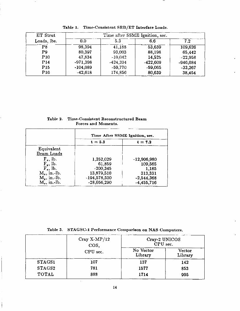
An overview of the pre-liftoff loads variations after SSME ignition is shown in figure 7. The loading cases considered in these analyses correspond to t = 0, 5.3, 6.6, and 7.2 seconds after SSME ignition. The time-consistent SRB/ET interface loads for these four “snapshots” in time are given in Table 1. At t = 0, the loads induced into the SRB are due to the eccentric weight of the orbiter and the external fuel tank and due to cryogenic shrinkage of the external tank during fueling. At SSME ignition, an eccentric thrust of approximately one million pounds is produced that causes the space shuttle to bend over to a maximum deflection (referred to as “max twang”) and then spring back towards its original static configuration. For STS 51-L, the maximum bending occurred at t = 5.3 seconds. The SSME reached full thrust approximately 6.6 seconds after ignition. At t = 6.6 seconds, the space shuttle system has fully rebounded and the signal is issued to ignite the solid rocket motor propellant. The SRM ignition pressure transient has a duration of approximately 600 milliseconds for the pressure to build up inside the solid rocket boosters.
The reconstructed beam forces and moments for the SRB/ETA ring interface shell analysis model are given in Table 2. The aft ET attachment loads are equally divided between the two ETA ring webs and applied as point forces. The reconstructed beam forces and moments are used to generate a statically equivalent set of shell stress resul- tants for inplane compression and shear.
Computational Approach The SRB analyses were performed using various NASA computer systems. The opera- tional aspects of using various computer systems including remote access to the Numer- ical Aerodynamic Simulator (or NAS)lo facility at the NASA Ames Research Center are described on figure 8. A Langley VAX computer is used for model preparation and verification. The datasets are then transmitted to the NAS computers for execution. The output files and restart files are returned to a Langley VAX computer for postpro- cessing. The output files and plot vector files are transmitted to the Langley central computer system for printing, microfiche generation, plotting, and archival storage. For example, a nonlinear analysis of the SRB is performed on the NAS Cray-2 computer and a restart file containing calculated displacement solution vectors is generated. Then the restart file is translated into ASCII format and transferred using the NASnet wide-area network to a Langley VAX computer. This ASCII file is converted back to a restart file for postprocessing. The output file ( 5 to 50 megabytes in size) generated on NAS is also returned to Langley and then transferred using the LaRCnet local-area network to the central computer site for making microfiche copies (7 to 25 microfiche). The post- processing of these results and the model verification task are performed on a Langley VAX computer system instead of the Langley central site CYBER computers because of the large memory requirements.
6

Computer Systems
In building the finite element models, calculating results, and evaluating the output, three different classes of computer systems are used ( i . ~ , workstations, minicomputers and supercomputers). A fourth class of computer system, the mainframe system, is used to store data, process microfiche, and produce report-quality graphics output.
The first class of computer system used in building and verifying the finite element models is a minicomputer. A VAX 11/785 minicomputer running the VMS operating system is used. Since the STAGSC-1 computer code is developed and enhanced under the VMS operating system, this computer system is a natural part of the overall comput- ing environment. The VAX 11/785 computer system allowed the finite element models to be generated, solutions using coarse grids to be computed, and “quick-look” graphics output to be evaluated prior to submitting large-scale analyses to the supercomputer.
The second class of computer system used to perform these analyses is a VAXsta- tion I1 GPX workstation running the ULTRIX operating system. This computer system provides basic communication between the VAX/VMS DECnet environment of a mini- computer and the UNIX TCP/IP environment of a supercomputer. The workstation capability also provides the “quick-look” graphics display to verify the model generation and to evaluate results.
The third class of computer systems used consists of supercomputers. The compu- tational portion of these analyses is performed on the NAS facility at the NASA Ames Research Center. The goals and objectives of the NAS require that the computer sys- tem hardware and software change. At the beginning of this project, the NAS computer environment was in transition. Cray Research, Inc. had delivered the first commercial Cray-2 supercomputer, and an interim Cray X-MP/12 was still on-site at Ames. Work at NAS began using the Cray X-MP/12 supercomputer running the COS operating sys- tem. This Cray X-MP/12 was made available for the initial phase of the work. When the initial phase of the work was completed, the Cray X-MP/12 was removed, and the STAGSC-1 code was ported to the Cray-2 to complete the preliminary analyses reported in this paper. The NAS Cray-2 supercomputer uses the UNICOSt operating system. Various upgrades occurred during the remainder of this activity as NAS transitioned through a Cray-2 running UNICOS 1.0, a Cray-2 running UNICOS 2.0, and finally to a Cray-2S running UNICOS 3.0.
Finally, the fourth class of computer system is the mainframe system. The Lang- ley Central Site mainframe environment, consisting of several CDC Cyber computers running the NOS operating system, provided a capability for producing printed out- put, mass storage for the large output files produced on the supercomputer, archival output in the form of microfiche, and report quality graphics. This local capability provided the labor intensive functions required throughout the distributed environment and complements the other distributed capabilities required for this project.
Network Access
The changes occurring in the field of computer networking represent probably the most dramatic changes affecting structural analysts over the period of this project. Network- ing removed the constraint of physical distance. Working remotely from the supercom- puters used in the computational phase of this project presented a new set of problems that, once solved, resulted in a unique new capability for the structural analysts.
t The UNICOS operating system is derived from the AT&T UNIX System V operating system. UNI- COS is also based in part on the Fourth Berkeley Software Distribution under license from The Regents of the University of California
7

The network at Langley uses Ethernet within buildings and a fiber optic Pronet 10 token-passing ring network called LaRCnet between Langley buildings. Initially the gateways between buildings would route only a Xerox XNS-based protocol developed at Langley. Connected to one of the Ethernets is a Vitalink Bridge that would route both TCP/IP and DECnet to the NAS facility at Ames over a 256 kilobits per second satellite link. The evolution of this network over the course of the project followed the networks being developed in industry over that time. Much of the communication was done manually at first. LaRCnet was used to copy files to a computer in the building that contained the Vitalink Bridge, and DECnet was used to cross the country to a staging computer at Ames, and then the Cray Station software on the Ames VMS VAX computer was used to complete the link. The steps would be reversed to bring data back to Langley. This communication path was simplified over the course of the project to the network now in place. Workstations in separate buildings are supported with routing gateways through the LaRCnet fiber optic system, which uses a Pronet P4200 gateway connected to the Vitalink directly. The communication link with Ames has been upgraded to a one megabit per second transfer rate (ix., T1 link) and it was discovered that a land line is preferable to a satellite link for interactive use. The result is that the miles between Ames and Langley are no longer a problem; researchers can use the NAS system at Ames as if it were located at Langley. The Cray-2 appears to the structural analyst as if it were embedded in the local workstation.
Performance The performance of the STAGSC-1 program on the Cray X-MP/12 and Cray-2 com- puter is shown in Table 3. Much of the early work was done without the advantage of FORTRAN optimization from the Cray-2 UNICOS 1.0 compiler due to the newness of the compiler and the errors in the compiler optimization. The Cray-2 flowtrace capabil- ity was used to identify the routines that required the most CPU time and efforts were directed at optimizing those routines. When the FORTRAN compiler optimization had been completed, the Cray-2 still took twice as long as the Cray X-MP/12 to perform a linear stress analysis of the SRB finite element model described in this paper. With the use of the Cray-2 vector library routine “dot”, the run time was decreased by a factor of two, achieving the same overall rate as the Cray X-MP/12. Increasing the amount of memory managed within the program itself also resulted in significant 1/0 savings. Since STAGSC-1 was designed on static memory machines, the program made use of blank common to provide out-of-core solutions. By controlling the amount of managed memory within the STAGSC-1 program (i.e., changing the size of the blank common), the 1/0 rate required for efficient execution could be balanced with the restrictions of the specific implementation of UNICOS job processing.
The NAS Cray-2 supercomputer has four processors, each with a clock cycle time of 4.1 billionths of a second and a total memory size of 256 million 64-bit words. This Cray- 2 is a supercomputer capable of over one hundred times the computational capability of a VAX 11/785 computer. In addition, the Cray-2 is a native 64-bit wordsize machine, and roundoff problems that are a problem on 32-bit machines are eliminated. The STAGSC-1 computer code, designed nearly fifteen years ago, uses basic algorithms that provide out-of-core solution methods that also work well on the Cray-2. Even with 256 million words of main memory, the larger matrices could not be held in memory. This application program made use of 60 million words of main memory (e.g., blank common is dimensioned to 32 million words) to avoid excessive 1/0 and to fit execution runs into the normal processing queues eliminating the need for special priority. Auxiliary data storage requirements for these analyses is another concern. During the large SRB
8
runs, a single temporary file requires in excess of 800 megabytes of storage. Hence, coordination or scheduling of these runs by the analyst is necessary to avoid exceeding the available auxiliary storage.
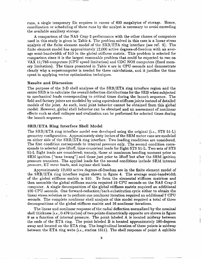
A comparison of the NAS Cray-2 performance with the other classes of computers used in this study is given in Table 4. The problem solved in this case is a linear stress iinalysis of the finite element model of the SRB/ETA ring interface (see ref. 5 ) . The iinite element model has approximately 12,000 active degrees-of-freedom with an aver- iige semi-bandwidth of 510 in the global. stiffness matrix. This problem is selected for comparison since it is the largest reasonable problem that could be expected to run on ’VAX 11/785 computers (CPU speed limitation) and CDC NOS computers (fixed mem- ory limitation). The times presented in Table 4 are in CPU seconds and demonstrate clearly why a supercomputer is needed for these calculations, and it justifies the time spent in applying vector optimization techniques.
!Results and Discussion The purpose of the 2-D shell analyses of the SRB/ETA ring interface region and the entire SRB is to calculate the overall deflection distributions for the SRB when subjected to mechanical loads corresponding to critical times during the launch sequence. The iield and factory joints are modeled by using equivalent stiffness joints instead of detailed models of the joint. As such, local joint behavior cannot be obtained from this global model. However, global shell behavior can be obtained and an assessment of nonlinear effects such as shell collapse and ovalization can be performed for selected times during the launch sequence.
SRB/ETA Ring Interface Shell Model The SRB/ETA ring interface model was developed using the original ( i . e . , STS 51-L) geometry configuration. Approximately sixty inches of the SRM motor case are modeled on either side of the SRB/ETA ring interface. Two loading conditions are considered. ’The first condition corresponds to internal pressure only. The second condition corre- sponds to selected pre-liftoff, time-consistent loads for flight STS 51-L. Two sets of STS !5l-L flight loads are considered; namely, those at maximum bending moment prior to SRM ignition ( “ m u twang”) and those just prior to liftoff but after the SRM ignition pressure transient. The applied loads for the second conditions include SRM internal ;?ressure, ET strut loads, and inplane shell loads.
Approximately 12,000 active degrees-of-freedom are in the finite element model of the SRB/ETA ring interface region shown in figure 4. The average semi-bandwidth of the global stiffness matrix is 510. To form the elemental stiffness matrices and then assemble the global stiffness matrix required 19 CPU seconds on the NAS Cray-2 computer. A single decomposition of the global stiffness matrix required an additional 100 CPU seconds. One forward-reduction/back-substitution cycle either to obtain the linear stress solution or to perform one nonlinear iteration required an additional 7 CPU ,seconds. The complete nonlinear shell analysis of this model required a total of three decompositions of the global stiffness matrix and 16 nonlinear iterations.
The linear and nonlinear response of the radial deflection normalized by the nominal shell thickness ( i . e . , 0.479 inches) of two points diametrically opposite are shown in figure 9 as a function of internal pressure. The point labeled A is located midway between the ends of the ETA ring. The point labeled B is located approximately 180-degrees away and located on the ETA ring. The longitudinal location of these points is midway between the ETA ring webs ( i . ~ , station 1511). The shell response of point A exhibits
9

significant nonlinearity. The radial deflection from the nonlinear solution for point A is nearly twice as large as the linear solution. Conversely, the shell response of point B is only mildly influenced by including the geometrically nonlinear effects and exhibits a stiffening trend.
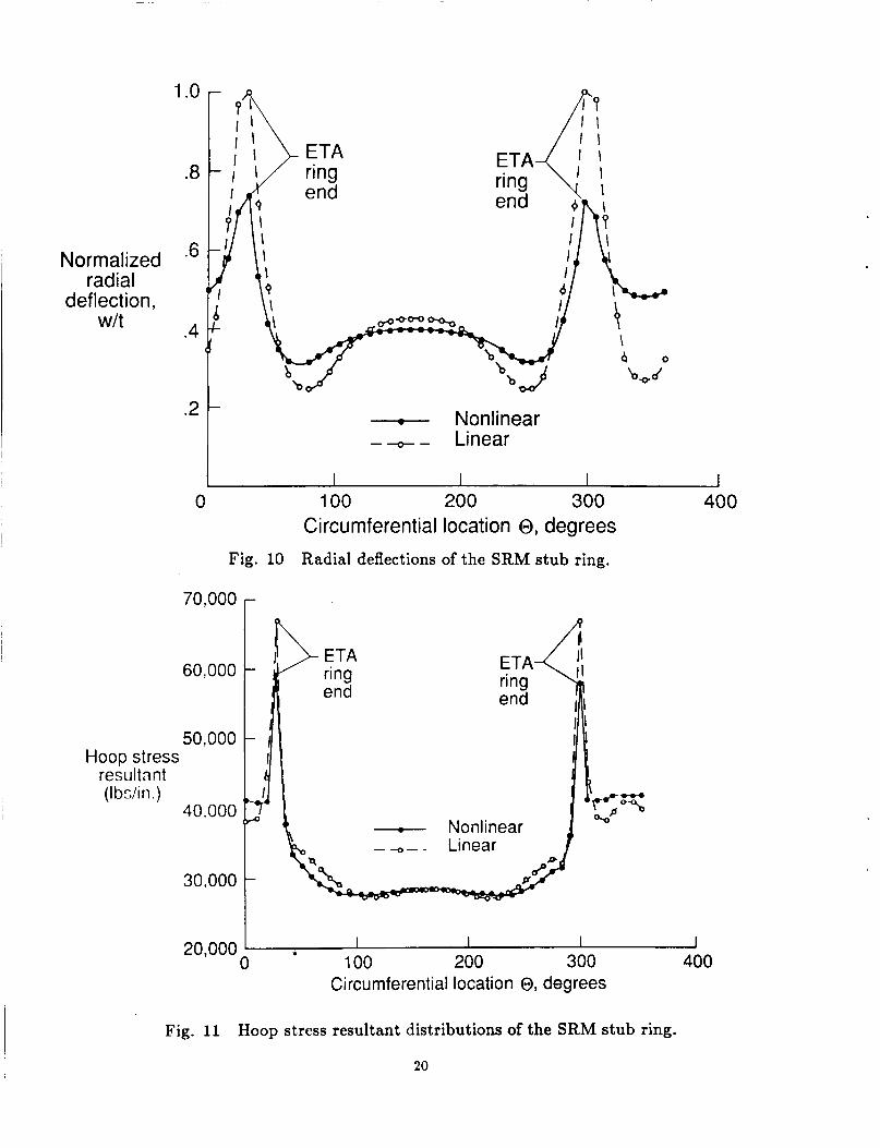
The radial deflection patterns of the SRM stub ring are shown in figure 10 for both the linear and nonlinear solutions for a 1000 psi internal pressure load. The radial deflections are normalized by the nominal shell thickness. At the ends of the ETA ring, the radial deflections from the linear analysis are equal to the shell thickness. This result indicates that a nonlinear analysis is required to predict accurately the structural response. The radial deflection pattern from the nonlinear analysis indicates a stiffening of the shell response due to the inclusion of geometric nonlinearities. These deflection patterns exhibit large changes in amplitude near the ends of the ETA ring.
The hoop stress distributions of the SRM stub ring are shown in figure 11 for the linear and nonlinear solutions for a 1000 psi internal pressure load. At the ends of the ETA ring, the hoop stress peaks due to the discontinuity in stiffness resulting from a partial ETA ring. The linear and nonlinear hoop stress distributions are similar, and their magnitudes are nearly the same except at the ends of the ETA ring. The nonlinear hoop stress at the end of the ETA ring is approximately 10% less than the linear hoop stress.
The linear and nonlinear solutions for the model of the SRB/ETA ring interface subjected to an internal pressure of 1000 psi are obtained. Deformed geometries with exaggerated deflections corresponding to the linear and nonlinear solutions are shown in figure 12. Deformed geometries of the entire model are shown in the upper half of the figure and those of the SRM stub ring alone are shown in the lower half. Both the linear and nonlinear solutions exhibit an abrupt change in deflections near the ends of the ETA rings. This high local bending causes large tangential shearing and normal forces to develop between the SRM stub rings and the ETA rings.
The axial distribution of the nonlinear radial deflections for the SRB/ETA ring interface model subjected to 1000 psi internal pressure only is shown in figure 13 for three circumferential locations. The radial deflections are normalized by the nominal shell thickness and are shown as a function of SRB station number. Station numbers corresponding to tang-clevis joint (field and factory) locations and the upper and lower ETA ring webs are also noted on the figure. The first circumferential location (point A) corresponds to midway between the ends of the ETA ring. The radial deflection pattern is denoted as the solid curve. This pattern exhibits a marked change in radial deflections near the field joint at station 1492 and is such that a tang-clevis joint would tend to open. The second location corresponds to point B which is approximately 180 degrees opposite to point A. The radial deflection pattern at this location is denoted by a dashed line. The pattern near the field joint is again similar to the patterns at the other locations. However, near the ETA ring webs the radial deflection pattern is different and the stiffening influence of the ETA ring on the shell response can be seen. The third location (point C) corresponds to an end of the ETA ring. The radial deflection at this location is denoted by a line with filled symbols. This pattern is similar to that of point A with the exception being an increase in amplitude of the radial deflections. For comparison, two additional curves are shown on figure 13. One curve represents the membrane solution, including the biaxial effect, for a uniform thickness (0.479 inches) cylindrical shell with an internal pressure of 1000 psi. The other curve represents the nonlinear solution for the same finite element model used to generate the other results except without the partial ETA ring. These radial deflection patterns from the nonlinear
10

solution also indicate that end effects due to imposed boundary conditions appear to be localized near the ends of the model. Also, these deflection patterns indicate that t‘he STS 51-L tang-clevis field joint at station 1492 would tend to open. However, these models only reflect STS 51-L geometry and not the new SRM joint redesign with an intcrfwence-fit capture feature that is tlcsigned to restrict the motion between the inner clevis arm and the tang. Extexisivc. aiialyt,ical studies are rcpor tcd ill rcfcrcnw 4 which describe the structural behavior of the original and modified tang-clevis joint designs. These studies included three-dimensional stress analysis, nonlinear contact, and correlation between test and analytical results.
Nonlinear analyses of the SRB/ETA ring interface model using the reconstructed loads for time t=5.3 and 7.2 seconds after SSME ignition have been performed. The non- linear radial deflections at the ETA ring normalized by the nominal SRB case thickness (0.479 inches) are shown in figure 14 as a function of circumferential location around the SRB. Time t=5.3 seconds corresponds to the time at which maximum bending (“max twang”) occurs. At this time, the SRM is unpressurized since it has not yet been ignited. The ET strut loads at maximum bending result in an asymmetric radial deflection pattern; however, the amplitudes of these deflections are small compared to either the nominal shell thickness or the radial deflections caused by internal pressure lloading only. Time t=7.2 seconds corresponds to the time at which the SRM reaches full pressure and liftoff occurs. At SRM pressurization, the overall shell response is dominated by the effects of the internal pressure, and the effect of the ET strut loads i,3 secondary.
These analytical results for the SRB/ETA ring interface indicate significant differ- ences between the linear and nonlinear deflection patterns. The loading component which has been shown to significantly affect the shell deflection patterns is the SRM internal pressure. Both the deflection pattern and the tangential shearing force distribu- tion changed only slightly when an axial force was combined with the internal pressure loading case. Two STS 51-L pre-liftoff, time-consistent loading cases have been consid- ered. The ET strut loads at maximum bending result in an asymmetric radial deflection pattern; however, the amplitudes of these deflections are small compared to either the nominal shell thickness or the radial deflections caused by internal pressure loading only. At SRM pressurization, the overall shell response has been shown to be dominated by the effects of the internal pressure.
Global SRB Shell Model The SRLI finite element model was also developed using the original (;.e., STS 51-L) SRB geomctry configuration. The loading cases considered in these analyses correspond to the loadings at t = 0, 5.3, 6.6, and 7.2 seconds after SSME ignition. These four loading cases are used to examine the extremes of the actual loading expected prior to liftoff. The time-consistent SRB/ET interface loads for these four points in time are given in Table 1.
Approximately 85,000 active degrees-of-freedom are in the finite element model of the entire SRB shown in figure 3. The average semi-bandwidth of the global stiffness matrix is 510. To form the elemental stiffness matrices and then assemble the global stiffness matrix required 101 CPU seconds on the NAS Cray-2 computer. A single decomposition of the global stiffness matrix required an additional 685 CPU seconds. One forward-reduction/back-substitution cycle either to obtain the linear stress solution or to perform one nonlinear iteration required an additional 45 CPU seconds. The complete nonlinear shell analysis of the model required a total of two decompositions
11

of the global stiffness matrix and 30 nonlinear iterations. The complete nonlinear shell analysis of the SRB for each pre-liftoff loading case required a total of nearly 3900 CPU seconds on the Cray-2. The same computation on a VAX 11/785 computer is estimated to take 7.4 CPU days.
At t = 0, the loads induced into the SRB’s are due to the eccentric weight of the Orbiter and ET and also due to cryogenic shrinkage of the ET during fueling. The t = 0 load case is included to investigate the initial static configuration prior to the ignition of the SSME’s. The SRB finite element model with exaggerated deflections from a nonlinear analysis for the t = 0 load case is shown in figure 15a.
When the SSME’s are ignited, an eccentric thrust of approximately 1,000,000 pounds is produced that causes the Space Shuttle to bend over to a maximum deflection (“max twang”). Maximum bending occurs at t = 5.3 seconds after SSME ignition. The SRB finite element model with exaggerated deflections from a nonlinear analysis for the t = 5.3 seconds load case is shown in figure 15b. Although the structural response of the SRB to the “max twang” loads at t = 5.3 seconds exhibits large deflections, the overall response as characterized by the SRB tip deflection is nearly linear as indicated in reference 4.
The SSME’s reach full thrust approximately 6.6 seconds after their ignition. At t = 6.6 seconds, the SRB has rebounded, and the signal is given to ignite the SRM propellant and to release the bolts in the hold-down post of the aft skirt. The SRB finite element model with exaggerated deflections from a nonlinear analysis for the t = 6.6 seconds load case is shown in figure 15c. Comparing the deformed geometries given in figure 15b for the “max twang” condition with that given in figure 15c for the SRM ignition condition indicates that the SRB is rebounding to its original position.
After approximately another 600 milliseconds (k., t = 7.2 seconds), the pressure inside the SRM has built up to nearly 1000 psi. The effect of the variation of the internal pressure distribution along the length of the SRM on the structural response is minimal. Since the SRB is not restrained to the launch pad at this time, liftoff occurs. However, the finite element model of the SRB for this load case assumes that the entire edge of the aft skirt is clamped so that the structural response for the pressurized SRM could be analyzed with the head pressure on the forward dome also applied. The SRB finite element model with exaggerated deflections from a linear analysis for the t = 7.2 seconds load case is shown in figure 15d. Comparing the deformed geometries given in figures 15a, 15b, and 15c for the unpressurized SRM condition with that given in figure 15d for the pressurized SRM condition indicates that the SRM field and factory joints influence the global structural response much like frames on an aircraft fuselage ( i . e . , they cause “pressure pillowing”).
The global structural response of the SRB to these four pre-liftoff loading cases (time-consistent SRB/ET interface loads for t = 0, 5.3’6.6, and 7.2 seconds after SSME ignition) is given in figure 15. These four loading cases are used to examine the extremes of the actual loading expected prior to liftoff. At t = 0, the SRB’s deflect toward the Orbiter due to the eccentric weight of the Orbiter and ET. At t = 5.3 seconds after SSME ignition, the SRB’s deflect to a maximum value due to the eccentric thrust of the SSME’s. At t = 6.6 seconds after SSME ignition, the SSME’s reach for thrust, the Space Shuttle system is rebounding to its vertical position, and the SRM’s are ignited. At t = 7.2 seconds after SSME ignition, the SRM’s reach maximum operating pressure and liftoff occurs. No evidence of nonlinear shell collapse was observed in these preliminary 2-D shell analyses of the SRB for the pre-liftoff loading cases considered.
12

Summary The SRB analyses reported in this paper utilized various NASA computer systems. In building the finite element models, calculating results, evaluating the output, generating report-quality graphics output, and providing archival storage of datasets and results, four different classes of computer systems are used (k, workstations, minicomputers, mainframes, and supercomputers). The computational approach using this variety of computer systems is described.
The results of these analyses represent a preliminary assessment of the overall struc- tural response of the SRB to selected pre-liftoff loads for STS 51-L. The present analyses neglect the effects of the SRM propellant and any dynamics. The field and factory tang- clevis joints are modeled as equivalent stiffness joints, and bolted connections (e.g., ETA rings) are modeled as “welded” sections. The overall structural response predicted by t,hese analyses characterizes the global shell behavior of the Space Shuttle SRB.
]Reference 8
1. Report of the Presidential Commission on the Space Shuttle Challenger Accident, Washington, D.C., June 6, 1986.
2. Greene, William H.; Knight, Norman F., Jr.; and Stockwell, Alan E.: Structural Behavior of the Space Shuttle SRM Tang-Clevis Joint. Journal of Propulsion and Power, Vol. 4, No. 4, July-August 1988, pp. 317-327. (Also NASA TM-89018, September 1986 .)
3. Christensen, N. G. : Supercomputing Gives a Boost to Shuttle Solid Rocket Mo- tor Redesign. Science and Engineering on Cray Supercomputers, Eric J. Pitcher (editor), Cray Research, Inc., pp. 109-125, 1988.
4. Knight, Norman F., Jr.; Gillian, Ronnie E.; and Nemeth, Michael P.: Preliminary 2-D Shell Analysis of the Space Shuttle Solid Rocket Boosters. NASA TM-100515, March 1988.
5. Knight, Norman F., Jr.: Nonlinear Shell Analyses of the SRB/ETA Ring Interface,
6. Anon., MSC/NASTRAN User’s Manual. MacNeal-Schwendler Corporation, Los Angeles, CA, 1985.
7. Almroth, B. 0.; Brogan, F. A.; and Stanley, G. M.: Structural Analysis of General Shells, Vol. 11, User Instructions for STAGSC-1, Report No. LMSC-D633873, Lockhccd Palo Alto Research Laboratory, Palo Alto, CA, December 1982.
8. Rankin, C. C.; Stehlin, P.; and nrogan, I?. A.: Enhancements t o the STAGS Com- puter Code, NASA CR-4000, November 1986.
9. Oostyen, J. E.; Bright, D. D.; Hawkins, G. F.; McCluskey, P. M.; and Larsen, G. L.: SRM Joint Deflection Referee Test: Phase 2 Final Report, Morton Thiokol, Inc., Wasatch Operations, Document Number T WR-300149, April 3, 1986.
Supercomputing in Aerospace, NASA CP-2454, pp. 13-21, 1987.
NASA TM-89164, July 1987.
:LO. Bailey, F. R.: NAS - Current Status and Future Plans.
13
ET Strut Loads, Ibs.
P8 P9 P 10 P 14 P15 P 16
Table 2. Time-Consistent Reconstructured Beam Forces and Moments.
Time after SSME Ignition, sec. 0.0 5.3 6.6 7.2
98,394 4 1,188 53,639 109,626 80,397 93,003 88,198 65,442 47,834 - 10,042 14,525 -22,958
-071,398 -424,394 -422,609 -946,084 -104,089 -59,7 70 -59,065 -33,267
-42,618 174,856 80,639 38,454
Equivalent Beam Loads
F,, lb. F,, lb. F,, lb.
M,, in.-lb. Mu, in.-lb. M,, in.-lb.
t = 5.3
1,252,029 61,859
-200,345 13,8 79,5 10
- 194,578,500 - 2 8,056,290
Time After SSME Ignition, eec.
t = 7.2
- 12,906,980 109,565
1,185 313,331
-2,544,368 -4,455,716
Cray X-MP/12
Table 3.
I-- Cray-2 UNICOS
STAGS1 STAGS2 TOTAL
cos, CPU see.
CPU sec. No Vector Vector
Library Library 107 78 1 888
137 142 1577 853 1714 995
14

__ -- - _____-
VAX 11/785 VMS 4.5, CPU sec.
901
18536
514
Form and Assemble Global Stiffness Matrix Decompose the Global Stiffness Matrix Forward/ B ac kw ar d Substitution and Stress Recovery
Total 19951
-=aunch platform
- - -
CDC 173 CDC 855 CRAY-2 NOS 2.4, NOS 2.4, IJNICOS 2.0, CPU sec. CPU sc'c. CPU sec.
4 78 96 18 .- __
9917 1983 96
236 47 7
10631 2126 121
Fig. 1 Space Shuttle system.
15

Inner clevis arm
clevis arm
Fig. 2 Solid rocket motor case joint cross section.
Forward cone
Aft ET attachment
Splashdown rings Field/factory joints
Aft skirt Field joint at station 1491
4 hold down pos
Fig. 3 Finite element model of entire SRB.
16

Forward end ETA ring \
Aft end LFactory
joint station 1577
Fig. 4 Finite element model of the SRB/ETA ring interface region.
strut P8
Fig. 5 Finite element model of ETA ring.
17

(toward Orbiter) Y (toward right wing) kP16 7
(toward Orbiter) Y (toward right wing) +PI 6
Right SRB p8
P9 J Forward ET attachment point (sta. 447.6) Aft ET attachment
points (sta. 151 1 .O)
__ ac h men t
r --- --- \---- 151 1 .O)
Fig. 6 SRB/ET interface loads.
SRB ignition (6.6 sec.) \
I
6 I I
Max twang - 5 f ignition (5.3 set.)
F x ' -5- 1 Axial force 0 -
10 IbS-10-
0 Time, seconds
50 Bending 0
-50 moment
M Y s -100 10 6 in. - lbs-150
J
-200 ' 1 1 1 I 1 1 I
0 1 2 3 4 5 6 7 8 9 10 Time, seconds
Fig. 7 Overview of pre-liftoff loads transient.
18

Minicomputers Datasets (40 Kbytes) Supercomputers
I Wide-area network
(200 Kbitskec)
Results (5 to 50 Mbytes) Y Modeling \ Postprocessing
Analysis
Local-area network
(256 Kbits/sec) I
Printout 0 Microfiche
Fig. 8 Remote access to NAS computers.
I1 n t e r n al pressure,
psi
1000
800
600
400
200
0 Normalized radial deflection, w/t
Fig. 9 Nonlinear shell response of the SRB/ETA ring interface region.
19
Normalized radial
deflection, wlt
1 .o
.8
.6
.4
.2 - Nonlinear --- Linear
70,000 r
60.000
50,000 Hoop stress
resultant (I bs/in .)
40,000
30.000
I I I 1 0 100 200 300 400
20,000 ' Circumferential location 0, degrees
Fig. 11 Hoop stress resultant distributions of the SRM stub ring.
20

(a) Linear solution. (b) Nonlinear solution. Fig. 12 Deformed geometries of the SRB/ETA ring interface
region finite element model.
21

1 .o
.8
0
.6 Normalized radial
deflection, w/t
.4
I I l l I 1 I I
-
I l l A (0 = 0")
I l l B (0 = 176") C (0 = 32")
-+- ---
3 1 1 Field joint sta. 1492
Membrane solution
I
7 I
1 .o
.5
Normalized
w/t at ETA ring
radial deflection, 0
-.5
I -1 .o
ETA ring / end
/ SRM pressurization t -= 7.2 sec
loads I PllO I t = 5.3 sec -
99 I p18 I I I
0 100 200 300 400 Circumferential location 0, degrees
Fig. 14 Nonlinear radial deflections of the SRM stub ring subjc3ctd to selected STS 51-L pre-liftoff loads.
22
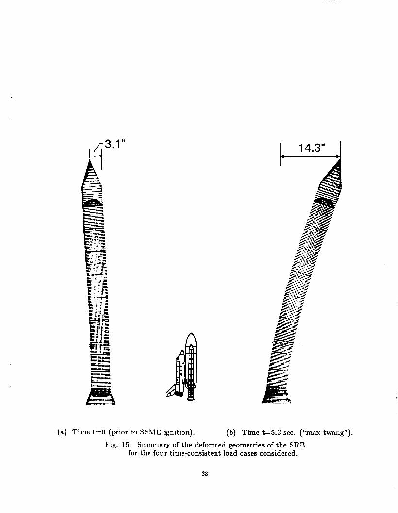
(a) Time t = O (prior to SSME ignition). (b) Time t=5.3 sec. ( “ m u twang”). I Fig. 15 Summary of the deformed geometries of the SRB
for the four time-consistent load cases considered.
23

I 6.7” i
(c) Time t=6.6 sec. (SRM ignition). (d) Time t=7.2 sec. (liftoff).
Fig. 15 Concluded.
24

- IWsA ‘1111, n , Report Documentation Page
L. Report No. NASA TM-101546
2. Government Accession No.
1. Title and Subtitle
Nonlinear Shell Analyses of the Space Shuttle Solid Rocket Boosters
9. Security Classif.(of thin report) Unclr~sified
r. Author(s)
Norman F. Knight, Jr., Ronnie E. Gillian, and Michael P. Nemeth
20. Security Clasaif.(of this page) 21. No, of Pages 22. Price Unclassified 25 A03
b . Performing Organization Name and Address
NASA Langley Research Center Hamlpton, VA 23665-5225
L2. Sponsoring Agency Name and Address
National Aeronautics and Space Administration Washington, DC 205480001
3. Recipient’s Catalog No.
- 5. Report Date
January 1989 6. Performing Organization Code
8. Performing Organhation Report No.
10. Work Unit No.
505-63-01-10 11. Contract or Grant No.
13. Type of Report and Period Covered
Technical Memorandum 14. Sponsoring Agency Code
.5. Supplementary Notes To appear as part of the Springer-Series on Computational Mechanics in the monograph entitled “Computational Mechanics of Nonlinear Behavior of Shell Structures,” W. B. Krutzig and E. Onate (Editors), 1989.
.- - 16. Abstract
A variety of structural analyses have been performed on the Solid Rocket Boosters (SRB’s) to provide information that would contribute to the understanding of the failure which destroyed the Space Shuttle Challenger. This paper describes nonlinear shell analyses that were performed to characterize the behavior of a.n overall SRB structure and a segment of the SRB in the vicinity of the External Tank Attachment (ETA) ring. Shell finite element models were used that would accurately reflect the global load transfer in a n SRB in a manner such that nonlinear shell collapse and ovalization could be assessed. The purpose of these analyses was to calculate the overall deflection and stress distributions for these SRB models when subjected to mechanical loads corresponding to critical times during the launch sequence. Static analyses of these SRB models were performed using a “snapshot picture” of the loads. Analytical results obtained using these models show no evidence of nonlinear shell collapse for the pre-liftoff loading cases con:iidered.
-_ 7. Key Words (Suggested by Authors(s))
Nonlinear Shell Analysis Computational Structural Mechanics Structural Analysis Solid Rocket Boosters Space Shuttle
18. Distribution Statement Unclassified-Unlimit ed
Subject Category 39