Embed Size (px)
Citation preview

NONLINEAR CONTROL AND DECISION MAKINGUSING FUZZY LOGIC IN LOGIX
AUTHORS: DAVE CARR, PROGRAM MANAGER & JEFF SHEARER, TECHNICAL CONSULTANT

Executive Summary This white paper explores fuzzy logic and how it helps engineers solve nonlinear control problems commonly found in process applications. Fuzzy logic, which mathematically emulates human reasoning, provides an intuitive way to design function blocks for intelligent control systems, advanced fault detection and other complex applications. Control systems deploying fuzzy logic can improve the management of uncertain variables, such as temperature fluctuations. This paper also provides best practices for designing with fuzzy control and examines its benefits compared to conventional control methods. In addition, this document outlines how to develop fuzzy logic algorithms for the Rockwell Automation Logix family of programmable automation controllers, using the RSLogix™ 5000 FuzzyDesigner software package. This paper also introduces the newest features of FuzzyDesigner, such as fuzzy logic add-on instructions. These features reduce development time, improve maintainability and ease set up of fuzzy logic programs. Highlights: • Learn how to translate empirical knowledge and heuristics into “if/then”
implications. • See how the theory of fuzzy control has evolved, since its introduction in
1965. • Understand best practices for designing fuzzy logic into a system. • Decompose a complex fuzzy system into smaller and simpler parts, reducing
the internal complexity of a fuzzy model. • Find out how to use RSLogix 5000 FuzzyDesigner, which is a fuzzy logic
software package for Rockwell Automation Logix controllers. • Read about six sample fuzzy logic projects, including “Fuzzy control of an egg
wash machine”, “Fuzzy PID gain scheduler for a thermal test chamber control”, “Expert diagnostic system for vibration diagnostics of a machine with transmission”, “Fuzzy supervised PI controller of a wet blend process” and “Fuzzy supervised state feedback controller of an inverted pendulum and crane system.”
RSLogix 5000 is a trademark of Rockwell Automation, Inc. RSLinx Classic is a registered trademark of Rockwell Automation, Inc. All trademarks not belonging to Rockwell Automation are property of their respective companies.

Contents
1. INTRODUCTION 1
2. FUZZY LOGIC ESSENTIALS 1
2.1 Benefits of Fuzzy Logic 1
2.2 Fuzzy Sets 1
2.3 Fuzzy Logic 3
2.4 Fuzzy Inference 5
2.5 Takagi-Sugeno Fuzzy Systems 9
3. FUZZY SYSTEM DESIGN GUIDELINES 10
4. RSLOGIX 5000 FUZZYDESIGNER 14
4.1 Component library overview 15
4.2 Developing Fuzzy Logic Solutions for Logix 16
5. FUZZY CONTROL 16
5.1 Performance Objectives and Design Constraints 17
5.2 Conventional Control 17
5.3 Fuzzy Control 18 5.3.1 Direct Fuzzy Control 18 5.3.2 Supervised Fuzzy Controller 19 5.3.3 Smart Switching Control 19
6. SAMPLE PROJECTS 23
6.1 Fuzzy Control of an Egg Wash Machine 24
6.2 Fuzzy PID Gain Scheduler for a Thermal Test Chamber Control 28
6.3 Expert Diagnostic System for a Machine Illustrating Hierarchical Fuzzy Systems 34
6.4 Fuzzy Supervised PI Controller of a Wet Blend Process 37
6.5 Fuzzy Supervised State Feedback Controller of an Inverted Pendulum and Crane System 40
7. REFERENCES FOR FURTHER READING 45
Nonlinear Control and Decision Making Using Fuzzy Logic in Logix Rockwell Automation 2 of 2

1. Introduction
This white paper discusses how to develop custom fuzzy logic algorithms for use in any Logix controllers using the RSLogix 5000 FuzzyDesigner software package to solve non-linear control problems. First, the paper provides a brief introduction to fuzzy logic. Then it summarizes guidelines for designing fuzzy control and fuzzy systems in general. Next come the aspects of conventional control and benefits of fuzzy control, along with typical structures of fuzzy controllers. Then, the paper introduces many of the features and capabilities added to RSLogix 5000 and the Logix platform through the use of fuzzy logic Add-On Instructions generated by the FuzzyDesigner. Finally, this paper describes sample projects demonstrating the value that fuzzy logic can offer for process-control applications.
2. Fuzzy Logic Essentials
2.1 Benefits of Fuzzy Logic
Fuzzy logic is a technique that attempts to systematically and mathematically emulate human reasoning and decision-making. Fuzzy logic allows engineers to exploit their empirical knowledge and heuristics represented in the “if/then” rules and transfer it to a function block. Fuzzy logic thus provides engineers with a clear and intuitive way to implement control systems, decision-making and diagnostic systems in various branches of industry. Fuzzy logic algorithms can be used for advanced applications in industrial automation such as:
• Intelligent control systems
Fuzzy control solutions are especially useful for complex systems where standard means such as PID control fails. Fuzzy logic can be an advantage in cases where an explicit analytical-process model is not available or is too complex. Another advantage of fuzzy logic is that it can be easily combined with conventional controllers and substantially enhance their functionality. For example, fuzzy rules interpolate between a series of locally linear controllers and schedule gains of a PID controller based on changing operating conditions. So fuzzy rules do not have to necessarily replace conventional control methods, but rather extend their capabilities.
• Process diagnostics, fault detection
If an analytical process model is not available or is too complex to be run in real-time, empirical knowledge can be used to classify process conditions and early detect faults.
• Decision-making and expert systems
Fuzzy rules can emulate an experienced human operator in real time, e.g. select appropriate ingredients, components or machines according to specific situations in the manufacturing process.
2.2 Fuzzy Sets
The concept of fuzzy sets was introduced by Prof. Lotfi Zadeh in 1965. Since then, the theory has been developed by many researchers and application engineers.
Nonlinear Control and Decision Making Using Fuzzy Logic in Logix Rockwell Automation 1 of 45

In classical set theory, a set is defined by a characteristic (membership) function that assigns each element a degree of membership: either 0 (the element is not member of the set) or 1 (the element is member of the set). Fuzzy sets generalize classical (crisp) sets and the degree of membership to a fuzzy set can take any value in the real unit interval [0, 1].
Let’s assume that we have defined three classical sets low, medium and high for variable temperature (see Fig. 1). If we want to classify (evaluate degree of membership) for example for value 95 [deg C] to these sets, we get value 1 for set medium and 0 for sets low and high. Vague classification will be more realistic and thus closer to human reasoning, because no sharp distinction usually exists between medium and high temperatures, as one temperature reading can be medium to some extent (0.8) and high to another one (0.2), see Fig. 2.
low medium high
range
20 150
temperaturetemperature
1
0
degree of membership(level of classification)
crisp value
1.0 mmediumedium
0.0 hhighigh0.0 lowow
ClassificationResult
[deg C]95
Fig. 1 Classic sets
low medium high
range
20 150
temperaturetemperature
1
0
degree of membership(level of classification)
crisp value
ClassificationResult
[deg C]95
0.8 mmediumedium
0.2 highhigh0.0 lowlow
Fig. 2 Fuzzy sets
More formally, a fuzzy set A is defined by its membership function A: X->[0,1], where X is a domain of elements (universe of discourse). For every particular value of a variable x ∈ X the degree of membership to fuzzy set A is A(x). In our particular example the variable x is temperature, X is the range [20, 150], A is e.g. medium and for x=95 we get medium(95)=0.8.
Nonlinear Control and Decision Making Using Fuzzy Logic in Logix Rockwell Automation 2 of 45

The variable x is called the linguistic variable and corresponding fuzzy sets defined on the range are called linguistic terms described by name (label) and membership function. For example the linguistic variable temperature has terms low, medium and high. The process of classification of a particular value of the variable x to corresponding fuzzy sets is called fuzzification.
The most commonly used membership functions are in Fig. 3. Singleton, whose degree of membership is 1 just for a single value c and 0 otherwise, is used just for output linguistic variables.
Trapezoid1
0a b c d
1
0a b c d
S-function1
0 c
Singleton
Fig. 3 Types of membership functions
2.3 Fuzzy Logic
Analogically fuzzy logic generalizes classic logic. So the degree of fulfillment (DOF) of any proposition does not have to be just true (1) or false (0), but also partially true (any value from the range [0, 1]). For example evaluation of the atomic fuzzy proposition “x is A” is DOF(A) = A(x). In our example if temperature=95 [deg C], we get the following evaluations (DOFs) of the fuzzy propositions:
• “temperature is low”: DOF(low) = low (95) = 0
• “temperature is medium”: DOF(medium) = medium(95) = 0.8
• “temperature is high”: DOF(high) = high(95) = 0.2
For another value of temperature we would get different DOFs of the fuzzy propositions.
Fuzzy Connectives
The elementary propositions can be further combined using “and,” “or” and “not” connectives to make compound fuzzy propositions.
Fuzzy AND Operator
Consider that we have the following fuzzy proposition.
“x is A” AND ”y is B”
Assume that the DOF(A) = A(x) and DOF(B) = B(y). Then the DOF of the combined fuzzy proposition is calculated using the so called T-norm operator (fuzzy AND):
DOF = T(A(x), B(y))
The most commonly used T-norm is the minimum T-norm (Tmin):
DOF = Tmin(DOF(A), DOF(B)) = min(DOF(A), DOF(B)) = min(A(x), B(y))
Nonlinear Control and Decision Making Using Fuzzy Logic in Logix Rockwell Automation 3 of 45
and the product T-norm (Tprod):
DOF = Tprod(DOF(A), DOF(B)) = DOF(A)*DOF(B) = A(x)*B(y)
Fuzzy OR Operator
Analogically consider that we have the following fuzzy proposition.
“x is A” OR ”y is B”
Then the DOF of the combined fuzzy proposition is calculated using the so called S-norm operator (fuzzy OR, T-conorm):
DOF = S(A(x), B(y))
The most commonly used S-norm is the maximum S-norm (Smax):
DOF = Smax (DOF(A), DOF(B)) = max(DOF(A), DOF(B)) = max(A(x), B(y))
Fuzzy NOT Operator
Analogically consider that we have the following fuzzy proposition:
“x is NOT A”
Then the DOF of this fuzzy proposition is calculated using fuzzy negation (NOT operator or complement):
DOF = 1-DOF(A) = 1-A(x)
Fuzzy Rules
Fuzzy “if/then” rules describe a relation between input and output linguistic variables in the following form:
IF condition THEN conclusion
The condition (also called premise or antecedent) is an atomic or compound fuzzy proposition regarding input linguistic variables and the conclusion (also called consequent) contains atomic fuzzy propositions regarding output linguistic variables. For example:
IF (x1 is A1) AND (x2 is A2) THEN (y is B)[RW]
[RW] is a rule weight from the unit range [0, 1] expressing designer’s confidence in the rule.
To evaluate an IF-THEN rule means to get DOF of the conclusion from the term DOFs used in the condition. First the condition part is evaluated to get rule DOF. Then the rule DOF is multiplied by the rule weight to get conclusion term DOF. For example the rule above is evaluated using T-norm Tmin as follows.
rule DOF = min(DOF(A1), DOF(A2))
DOF(B) = RW*(rule DOF)
If several rules have the same conclusion, then the resulting term DOF of the conclusion is calculated as maximum of values received from evaluation of individual rules. For example:
Nonlinear Control and Decision Making Using Fuzzy Logic in Logix Rockwell Automation 4 of 45

1. IF (x1 is A1) AND (x2 is A2),THEN (y is B)[RW1]
2. IF (x1 is A3) AND (x2 is A4), THEN (y is B)[RW2]
DOF(B) = max(RW1*(rule 1 DOF), RW2*(rule 2 DOF))
2.4 Fuzzy Inference
Fuzzy System
A fuzzy system is given by
• input linguistic variables along with definitions of linguistic terms
• output linguistic variables along with definitions of linguistic terms
• fuzzy “if/then” rules (rule base)
Fuzzy Inference
A fuzzy inference is a mechanism for evaluation of the fuzzy system, i.e. computing output values from input values. The fuzzy inference consists of the following steps.
1. Fuzzification: Inputs are classified to corresponding linguistic terms to get term DOFs.
2. Fuzzy rules evaluation: Term DOFs of conclusions are calculated from term DOFs of conditions
3. Defuzzification: Output linguistic terms are converted to a real crisp value according to their DOFs.
Defuzzification Methods CA – centroid average. Assume that an output linguistic variable has n terms of singleton
type with parameters ci and the term DOF of the i-th term is DOFi. The CA defuzzification method calculates the output value y* as an weighted average of the singletons
∑
∑
=
=
⋅= n
ii
n
iii
DOF
cDOFy
1
1*
1
0 ci ci+1
DOFi
DOFi+1
. . .. . .
y*
The method is continuous, so it is used for applications where a smooth input-output functions is needed (e.g. fuzzy control).
MOM – mean of maxima. As the output value y* is selected singleton ci with maximal DOF. If there are more singletons with the same maximal DOF, then the output is calculated as the average of these singletons.
Nonlinear Control and Decision Making Using Fuzzy Logic in Logix Rockwell Automation 5 of 45

SOM – smallest of maxima. As the output value y* is selected singleton ci with maximal DOF. If there are more singletons with the same maximal DOF, then the output is calculated as the minimal (leftmost) singleton.
LOM – mean of maxima. As the output value y* is selected singleton ci with maximal DOF. If there are more singletons with the same maximal DOF, then the output is calculated as the maximal (rightmost) singleton.
These methods are discontinuous and are used for applications where we select just one alternative from many (e.g. classification).
If no rule relevant to the corresponding output linguistic variable is activated (all terms DOFs are zero), then a default value defined by the designer is sent to the fuzzy system output.
Fuzzy Inference Example
Assume a control system for washing eggs with the following variables.
Process variables (inputs to the controller):
• Egg dirt (signal name: egg_dirt)
• Hot water flow rate sprayed by water washer on eggs (signal name: flow_rate)
Control variables (output from the controller):
• Water-valve position change (signal name: position_change). The signal is used as a change in the water-valve position.
All the signals are normalized to the interval [0, 1]. An experienced human operator described verbally his control strategy by the following rules.
1. IF (egg_dirt IS low) AND (flow_rate IS low) THEN (position_change IS zero)[1]
2. IF (egg_dirt IS low) AND (flow_rate IS high) THEN (position_change IS negative)[1]
3. IF (egg_dirt IS acceptable) THEN (position_change IS zero)[1]
4. IF (egg_dirt IS high) AND (flow_rate IS low) THEN (position_change IS positive)[1]
5. IF (egg_dirt IS high) AND (flow_rate IS high) THEN (position_change IS zero)[1]
The membership functions for the linguistic terms used in these rules are depicted in Fig. 4.
Nonlinear Control and Decision Making Using Fuzzy Logic in Logix Rockwell Automation 6 of 45

Fig. 4 Linguistic variables and their terms
Now consider that the actual values of the input variables are: egg_dirt = 0.12, flow_rate = 0.4. The fuzzy system is evaluated as shown in Fig. 5. Resulting output is position_change = -0.00962.
Nonlinear Control and Decision Making Using Fuzzy Logic in Logix Rockwell Automation 7 of 45

termDOF
low0.3
acceptable0.7
high0.0
low0.8333
high0.1667
rule DOF
[RW]
AND
min
AND
min
AND
min
AND
min
AND
min
AND
min
AND
min
AND
min
AND
min
AND
min
termDOF
negative0.1667
zero0.7
positive0.0
Rule 1 Rule 2 Rule 3 Rule 4 Rule 5
[1] *[1] * [1] *[1] * [1] *[1] * [1] *[1] * [1] *[1] *
maxmax maxmax maxmax
0.3 0.1667 0.7 0.0 0.0
0.3 0.1667 0.7 0.0 0.0
egg_dirt flow_rate
position_change
Def
uzzi
ficat
ion
Rul
e ba
se
eval
uatio
nFu
zzifi
catio
n
CentroidAverage
Fig. 5 Fuzzy inference
The complete input-output mapping produced by the fuzzy system is in Fig. 6.
Nonlinear Control and Decision Making Using Fuzzy Logic in Logix Rockwell Automation 8 of 45

egg_dirt
low
acceptable
high
flow_rate
low
high
nega
tive
zero
posi
tive
posi
tion_
chan
ge
Rule 4
Rule 3 Rule 5Rule 1
Rule 2
Fig. 6 Nonlinear input-output mapping produced by the fuzzy system
2.5 Takagi-Sugeno Fuzzy Systems
In the Takagi-Sugeno (TS) fuzzy system the conclusion of the rule is not a fuzzy set but a crisp function of the inputs. For example:
IF (x1 is A1) AND (x2 is B1) THEN y = f1(x) = c10+c11x1+ c12x2
IF (x1 is A2) AND (x2 is B2) THEN y = f2(x) = c20+c21x1+ c22x2
The functions f(x) of the input vector x = [x1, x2, ..] can generally be very complex but the most commonly used function is linear function described by the coefficients [c0, c1, c2, ..].
The TS fuzzy inference is very similar to the fuzzy inference described in the previous section with singletons in conclusions and CA defuzzification. But instead of the weighted average of the singletons we calculate weighted average of the functions in conclusions evaluated for the current values of inputs.
Assume that the output variable y has n functions fi(x) given by coefficients [ci0, ci1, ci2, ..] and the DOF of the conclusion corresponding to fi(x) received form evaluation of rules is DOFi. The TS inference method calculates the output value y* as the weighted average of the functions:
Nonlinear Control and Decision Making Using Fuzzy Logic in Logix Rockwell Automation 9 of 45

∑
∑
∑
∑
=
=
=
=
+++⋅=
⋅= n
ii
n
iiiii
n
ii
n
iii
DOF
xcxccDOF
DOF
xfDOFy
1
122110
1
1*...)()(
TS Fuzzy Inference Example
Assume we have three local linear models and the interpolation between them is described by the following rules.
IF (x is low) THEN y = 10
IF (x is medium) THEN y = 6x-2
IF (x is high) THEN y = -10x+100
The input-output mapping of the TS fuzzy system is shown in Fig. 7.
y
x
y = 10
y = 6x-2
y = -10x+100
Fig. 7 Takagi-Sugeno fuzzy system interpolates between 3 linear functions
3. Fuzzy System Design Guidelines
This section provides guidelines for designing fuzzy systems. The reader should keep in mind that these guidelines are just general recommendations, because the design of a fuzzy system depends on the particular application.
1. Analyze the purpose of the fuzzy system, and identify relevant input and output linguistic variables.
Nonlinear Control and Decision Making Using Fuzzy Logic in Logix Rockwell Automation 10 of 45

2. Define a range for each variable. The range is typically based on the limits of signals identified from historical records, limits of sensors, physical limits of facilities etc.
3. Cover the range of input linguistic variables by fuzzy sets (i.e. define input linguistic terms).
Select the number of terms. o The most common number of terms for input linguistic variables is 2, 3, 5 or 7. As
a general rule-of-thumb, start with 3 terms by default. Select the type of membership functions. Trapezoids are usually selected by default. S-
shaped functions result in a smoother input-output function, but evaluation is slightly slower. To compare typical input-output functions produced fuzzy system with trapezoids and S-functions see Fig. 8 and Fig. 9.Error! Reference source not found.
Fig. 8 Input-output function produced by fuzzy system with trapezoid membership functions and T-norm Tmin
Nonlinear Control and Decision Making Using Fuzzy Logic in Logix Rockwell Automation 11 of 45

Fig. 9 Input-output function produced by fuzzy system with s-shaped membership functions T-norm Tmin
Specify parameters (positions) of membership functions. According to the meaning of the respective term, specify typical value or interval. This interval corresponds to parameters b and c of trapezoid as shown below.
1
0a b=c d
typical value
1
0a b c d
typical interval o For the left-most term, always set parameters a and b equal to the lower limit of
the range (see term low in Fig. 10). o For the right-most term, always set parameter c and equal d to the upper limit of
the range (see term high in Fig. 10). o For the adjacent terms, set the parameter c of the left term equal to the
parameter b of the right term as shown in Fig. 10.
low medium high
range
20 150
1
0
Fig. 10 Recommended settings of membership-functions parameters
4. Cover the range of output linguistic variables by fuzzy sets (i.e. define output linguistic terms).
Nonlinear Control and Decision Making Using Fuzzy Logic in Logix Rockwell Automation 12 of 45

Select the number of terms. o Output linguistic variables usually contain more terms than inputs linguistic
variables and the number of terms varies with number of rules, because the terms define prototype outputs. So define one term (singleton) for each prototype output. If two terms are very near each other with respect the range, merge them to a single one.
Select the type of membership functions. Singletons are recommended to use by default because trapezoids are converted to singletons in the process of defuzzification.
5. Select the defuzzification method for output linguistic variables.
For the applications where the output is to be a continuous and smooth function of inputs (e.g. fuzzy control), select the CA defuzzification method.
For the applications where the purpose is to select just one from several alternatives (e.g. classification), select the MOM, SOM or LOM defuzzification method.
6. Specify default values for output linguistic variables. The default value is applied when no output linguistic term is activated (no rule is relevant for this combination of inputs values).
7. Enter fuzzy rules. For fuzzy systems with many inputs and rules, try to decompose rule base into hierarchical one. For an example of the decomposition see the sample project: Expert Diagnostic System for a Machine Illustrating Hierarchical Fuzzy Systems
8. Specify T-norm type used in fuzzy rules. T-norm Tmin is recommended because it is easier to analyze evaluation of fuzzy rules. You can easily identify the part of the condition that cased the rule is activated to such a degree (simply find the minimal term DOF) as compared with T-norm Tprod. In applications where smoothness of the input-output function plays an important role, select T-norm Tprod (compare Fig. 11Error! Reference source not found. and Fig. 8)
Fig. 11 Input-output function produced by fuzzy system with trapezoid membership functions T-norm Tprod
Nonlinear Control and Decision Making Using Fuzzy Logic in Logix Rockwell Automation 13 of 45

9. Analyze and tune the resulting fuzzy system.
Set values of individual inputs and see if the output is equal to an expected value. If not, analyze the fuzzy inference process – what rules and terms are activated to what degree – and modify parameters of membership functions or change rules.
Analyze input-output mapping using 3D graph tool. Select 2 inputs and 1 output, and plot corresponding mash. Modify the other inputs that serve as a parameter of the mash plot and analyze their effect.
10. Test the fuzzy system and fine tune the parameters of membership functions on the fly.
4. RSLogix 5000 FuzzyDesigner
RSLogix 5000 FuzzyDesigner is a software package for designing hierarchical fuzzy systems for Logix controllers. FuzzyDesigner includes a library of components from which a fuzzy system performing nonlinear input-output mapping can be designed. The hierarchical structure enables the designer to decompose a complex fuzzy system into smaller and simpler parts, reducing the internal complexity of a fuzzy model and resulting in fewer fuzzy rules and easier insight into the system operation.
Expert knowledge
fastisythenmediumisxandlowisxif
1
21
y1
FuzzyDesigner
Control Systems- controller- supervisor- process model
Process Diagnosis- process state classification
Forecasting- prediction model
Decision Making- decision support system
From
For
Generatesx1x2
xm
y2
yn
Add-on Instruction y1
FuzzyDesigner offers several methods for fuzzy system analysis. Simulation mode allows you to watch the influence of individual component values. 2D and 3D graphs with many options allow insight into the complex nonlinear mappings realized by the fuzzy algorithm.
The fuzzy system designed in the FuzzyDesigner can be exported to an Add-On Instruction (AOI) in L5X file format. The user can then import the fuzzy AOI into RSLogix 5000 projects. Fuzzy AOI’s, like any other AOI, can be used by any of the programming languages (Function Block Diagram, Ladder Logic, or Structured Text). Finally, FuzzyDesigner allows the user to online monitor and tune the fuzzy AOI directly in the running Logix controller.
Nonlinear Control and Decision Making Using Fuzzy Logic in Logix Rockwell Automation 14 of 45

4.1 Component library overview
The FuzzyDesigner Component Library offers components from which you can assemble fuzzy systems ranging from single-input/single-output systems to multiple-input/multiple-output systems with a complex hierarchical structure of rules:
Input Port preprocesses and stores values of a fuzzy system input variables
Output Port stores values of a fuzzy system output variables
Input Linguistic Variable
stores linguistic terms and implements fuzzification
Rule Block stores rules and computes DOFs of rule conclusions from DOFs of conditions i.e. evaluates fuzzy rules
Intermediate Linguistic Variable
is a bridge for logical chaining of rule blocks
Output Linguistic Variable
stores linguistic terms and computes the output value from DOFs of stored terms, i.e. implements defuzzification
Output Takagi-Sugeno Variable
stores parameters of functional terms and implements Takagi-Sugeno fuzzy inference
PID Controller allows intelligent supervision of a built-in PID controller
Component interface
The connection between components is called a link. Generally, an HFS computes with data in the form of a crisp (real) value and/or degrees of fulfillment (DOF) values. Not all components allow both types of data to be transferred over the link. Data types on both ends should match. FuzzyDesigner uses icons to define a link type as follows:
crisp value (input/output value link) – input crisp values and crisp values resulting from defuzzification are transferred over the link
crisp value (input/output value link) – crisp values are transferred over the link
DOF value (input/output logical link) – degrees of fulfillment of fuzzy terms of a fuzzy variable are transferred over the link to a rule block
DOF value (input/output logical link) – degrees of fulfillment of fuzzy terms
Nonlinear Control and Decision Making Using Fuzzy Logic in Logix Rockwell Automation 15 of 45
resulting from rule block evaluation are transferred over the link to a fuzzy variable
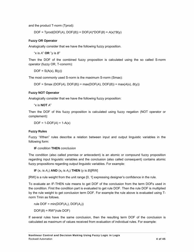
4.2 Developing Fuzzy Logic Solutions for Logix
Development cycle consists of the following steps:
Design fuzzy system in FuzzyDesigner
Generate the fuzzy Add-on Instruction
Integrate (import and instantiate) the fuzzy AOI to your RSLogix 5000 project
Monitor and tune the fuzzy AOI running in Logix on-line from FuzzyDesigner
5. Fuzzy Control
When confronted with a control problem for a complex process, a control engineer followssystematic design procedures. After gaining an intuitive understanding of the process dynamicsand establishing control design objectives, the control engineer typically solves the controlproblem by doing the following:
• Developing a model of the process dynamics
FuzzyDesigner RSLogix5000
FuzzyDesigner
monitoringtuning
OPCmonitoringtuning
OPC
RSLinx® Classic
Add-OnInstruction(.L5X)
Add-OnInstruction(.L5X)
Add-OnInstruction(.L5X)
RSLogix 5000
Logix
Nonlinear Control and Decision Making Using Fuzzy Logic in LogixRockwell Automation 16 of 45

• Using the mathematical model to design a controller, e.g. via a linear model, develop a linear controller with techniques from classical control
• Using the mathematical model of the closed-loop control system, and mathematical or simulation-based analysis to study the control-system performance
• Implementing the controller and evaluating the performance on the real process
Conventional Control approaches with PID, lead-lag or state-feedback controllers employ a process model described by differential equations assumed to be built. But Fuzzy Control focuses on gaining intuitive understanding of how to best control the process and this information is then loaded directly into the fuzzy controller.
While differential equations are the language of conventional control, heuristics and expert rules about how to control the process are the language of fuzzy control.
5.1 Performance Objectives and Design Constraints
The performance objectives usually involve the following factors:
• Disturbance-rejection properties
• Insensitivity to process parameter variations
• Stability
• Rise time
• Overshoot
• Settling time
• Steady state error.
Other technical factors of equal or even greater importance must also be considered:
• Cost of design, implementation and installation
• Computational complexity
• Reliability
• Maintainability
• Adaptability
• Understandability
• Politics
5.2 Conventional Control
Conventional control has provided numerous methods for designing controllers for dynamic systems. Some of the conventional design methods are listed below:
• PID (90% of control problems are solved by this simple, reliable and easy-to-understand control law, where the architecture of the controller is given and the task is just to set its
Nonlinear Control and Decision Making Using Fuzzy Logic in Logix Rockwell Automation 17 of 45

parameters properly. Often heuristics are used to tune its parameters.)
• Classical (lead-lag compensation, Bode and Nyquist methods, root-locus)
• State-space (state feedback, observers)
• Optimal (linear-quadratic regulator, use of dynamical programming)
• Robust (H2 and Hinf methods, quantitative feedback theory, loop shaping)
• Nonlinear (feedback linearization, Lyapunov redesign, sliding mode)
• Adaptive (MRAC, self-tuning regulators)
• Stochastic (Minimum variance, LQG)
The conventional techniques utilize mathematical models of the controlled process and the control task. Unfortunately, when using approaches to conventional control, some engineers ignore useful heuristics because they do not fit into the proper mathematical framework. This can cause problems.
5.3 Fuzzy Control
The task of modeling complex real-world processes for control-system design is difficult. Even if a relatively accurate model of dynamic system can be developed, it is often too complex to use in controller development as much simpler (e.g. linear) process model is required by most of the conventional control-design techniques. In practice, heuristics are used to modify the original design based on a simplified process model once the algorithm is implemented and confronted with reality.
5.3.1 Direct Fuzzy Control The fuzzy system designed and generated by FuzzyDesigner might be used in control systems, for example, as a direct nonlinear fuzzy-rule-based controller, PID feedback-control-system supervisor or a process model in a Model Predictive Control scheme. See figures below. Input and output filters shown in the figures are used for signal preprocessing such as filtering, deriving trends and many other functions that might add dynamics to the static I/O map generated from fuzzy rules. Input filters can also be designed in FuzzyDesigner. Output filtering is an option and contains, for instance, a discrete integrator fed by the output of the Fuzzy add-on instruction.
PLANTPLANTFUZZY CONTROLLER
ControlVariables
Setpoints
Input filter Output filter
Control system status Primary controls
Process Variables
PLANTPLANTFUZZY CONTROLLER
ControlVariables
Setpoints
Input filter Output filter
Control system status Primary controls
Process Variables
Fig. 12 Feedback control system with direct fuzzy controller
Nonlinear Control and Decision Making Using Fuzzy Logic in Logix Rockwell Automation 18 of 45
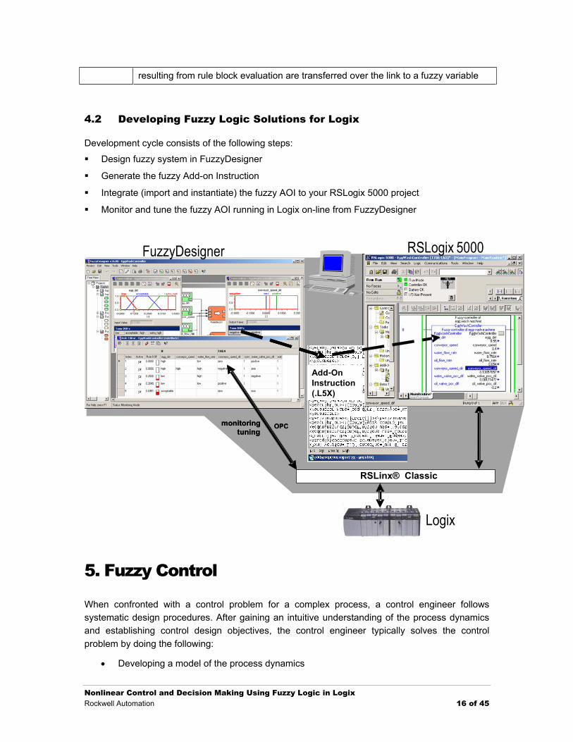
5.3.2 Supervised Fuzzy Controller A fuzzy controller with the above structure typically handles multiple inputs and generates multiple outputs. A disadvantage is that it is recommended for experienced designers, because control variables are direct functions of rules. The number of rules increases rapidly with the number of inputs and fuzzy terms for inputs. But the problem of dimensionality can be reduced by hierarchical structuring of the controller rule base, which is supported by FuzzyDesigner.
SP
PV
FUZZY SUPERVISOR
FUZZY SUPERVISOR
PLANTPLANT
PIDgains
CVPID
CONTROLLERPID
CONTROLLER
feedforward
Plant States
SP
PV
FUZZY SUPERVISOR
FUZZY SUPERVISOR
PLANTPLANT
PIDgains
CVPID
CONTROLLERPID
CONTROLLER
feedforward
Plant States
Fig. 13 Nonlinear, fuzzy-rule-based supervisor of a PID controller
The great advantage of a fuzzy supervision is that it can be applied to existing control with little danger of errors in design. A supervised PID controller is most frequently used where PID gains, feedforward action or s are being modified on-the-fly, using rules that depend on the process status and external conditions defined through s.
5.3.3 Smart Switching Control Another popular control structure with fuzzy logic is smart switching between local controllers. A local controller is an analytical controller designed to work around specific process operation conditions. Once the conditions change, the rule-based supervisor decreases the influence of one controller and gives more weight to another controller that has been designed to work in the new conditions.
Nonlinear Control and Decision Making Using Fuzzy Logic in Logix Rockwell Automation 19 of 45

CONTROLLER 1
CONTROLLER 1
CONTROLLER 2
CONTROLLER 2
CONTROLLER 3
CONTROLLER 3
FUZZY SUPERVISORFUZZY SUPERVISOR
+
+
+
SetpointsPLANTPLANT
×
×
Process Variables
Plant State
Schedule weights ∈ [0,1]
CV
×
CONTROLLER 1
CONTROLLER 1
CONTROLLER 2
CONTROLLER 2
CONTROLLER 3
CONTROLLER 3
FUZZY SUPERVISORFUZZY SUPERVISOR
+
+
+
SetpointsPLANTPLANT
×
×
Process Variables
Plant State
Schedule weights ∈ [0,1]
CV
×
Fig. 14 Smart switching between conventional controllers, Takagi-Sugeno Controller
Designing nonlinear feedback-control systems is generally a tough task. Building local controllers and combining their function using an interpolation scheme is usually easier than designing a single non-linear controller that operates globally and meets the criteria in the complete range of operating conditions. Local controllers are assumed to be linear dynamical systems specifically designed and tuned for particular operating conditions; that way, they guarantee closed-loop stability and other performance measures in the neighborhood of the specific process state.
Assume a single-input/single-output feedback-control system having one process variable (PV) and one manipulated (control) variable (CV). The task is to design a control system for the non-linear dynamical process that tracks a set-point.
There are three tasks for the designer:
• design local linear controllers
• observe the process and estimate the operating conditions to identify which local controller should be used at the moment
• combine local controllers with the decision scheme
Local linear controllers
Assume that the local controllers have been provided in the form of higher-order difference equation
)()()()1()( 01 mkeb kebnkuakuaku mn −+++−−−−−= LL ,
where u is the controller output and e is the controller input (control error, difference between the SP and PV). Index k is the sampling instant and a1, a2, …, an, b0, b1, …, bm are controller parameters. The actual output of the controller is a function of past outputs and the current and past inputs. Note that any linear dynamical system, including the PID, can be expressed in such a format.
Nonlinear Control and Decision Making Using Fuzzy Logic in Logix Rockwell Automation 20 of 45

Operating Conditions Classifier
There are situations where estimating operating conditions and their classification into finite number of classes based on limited number of available measurements and other process related information is uncertain. The existence of uncertainty and qualitative nature of such a task gives Fuzzy Logic some advantage. This task is efficiently solved using FuzzyDesigner.
Integrated Scheme
The remaining task is merging local controllers and process conditions classifier into a single scheme where output of rules, designed and implemented in FuzzyDesigner, gradually enable and disable outputs of local controllers. To assure bumpless transition between local controllers, the global output of the controller (CV) is fed back so the internal state of local controller(s) follows the one that influences the CV. More than two local linear controllers can be used. More than one local controller might be fired at the same time.
FuzzyDesigner block library offers a function called “Output Takagi-Sugeno Variable,” which can be efficiently used in the weighting scheme so it becomes an inherent part of the AOI generated. See Fig. 15 and the detail in Fig. 16. The AOI includes all the parameters required for the controller. The only functionality of the controller that remains external to AOI is delay lines providing past values of Control Error and Control Variable.
The general block diagram of the resulting scheme looks as follows. Local linear controllers could be implemented as AOIs in RSLogix 5000 v16, while the supervisor (blue block) that gradually activates and deactivates local controllers will be designed in FuzzyDesigner and imported to the RSLogix project as AOI.
Nonlinear Control and Decision Making Using Fuzzy Logic in Logix Rockwell Automation 21 of 45

unitdelay
unitdelay
...
uu(k-1)
u(k-n)
1
n
unitdelay
unitdelay
...
e e(k)
e(k-1)
e(k-m)
1
m
local linearcontroller 1
local linearcontroller 2
...
ProcessProcess
SP
PV
PVCV
+
-
...
u(k-1)
u(k-n)
e(k)
e(k-1)
e(k-m)u1(k)
...-
-
...
+
+
+
u(k-1)
u(k-n)
e(k)
e(k-1)
e(k-m)u2(k)
...-
-
...
+
+
+
×
+
+
FuzzyDesignerAOI
×
a11
a1n
...
b11
b1m
...
b10
a21
a2n
...
b21
b2m
...
b20
Smart switching
unitdelay
unitdelay
...
uu(k-1)
u(k-n)
1
n
unitdelay
unitdelay
...
e e(k)
e(k-1)
e(k-m)
1
m
local linearcontroller 1
local linearcontroller 2
...
ProcessProcess
SP
PV
PVCV
+
-
...
u(k-1)
u(k-n)
e(k)
e(k-1)
e(k-m)u1(k)
...-
-
...
+
+
+
u(k-1)
u(k-n)
e(k)
e(k-1)
e(k-m)u2(k)
...-
-
...
+
+
+
×
+
+
FuzzyDesignerAOI
×
a11
a1n
...
b11
b1m
...
b10
a21
a2n
...
b21
b2m
...
b20
Smart switching
Fig. 15 Smart switching as non-linear feedback-control system
Nonlinear Control and Decision Making Using Fuzzy Logic in Logix Rockwell Automation 22 of 45

Fig. 16 Smart switch and local linear controllers realized in FuzzyDesigner - example
6. Sample Projects
The chapter presents several sample fuzzy projects listed below to illustrate typical situations where fuzzy logic solutions fit.
• Fuzzy Control of an Egg Wash Machine. This is a getting started fuzzy project illustrating direct fuzzy controller that emulates control strategy of a human operator.
• Fuzzy PID Gain Scheduler for a Thermal Test Chamber Control. A typical nonlinear heat/cool control problem where standard PID control fails, but in combination with fuzzy PID gain scheduling it achieves defined control objectives.
• Expert Diagnostic System for a Machine Illustrating Hierarchical Fuzzy Systems. The project demonstrates how to build hierarchical fuzzy systems by chaining fuzzy rules.
• Fuzzy Supervised PI Controller of a Wet Blend Process. A real word application from food industry demonstrating how to schedule PID gains.
• Fuzzy Supervised State Feedback Controller of an Inverted Pendulum and Crane System. An example illustrating functionality of the Takagi-Sugeno fuzzy system as a
Nonlinear Control and Decision Making Using Fuzzy Logic in Logix Rockwell Automation 23 of 45

bumpless switch between local linear state feedback controllers.
6.1 Fuzzy Control of an Egg Wash Machine
The egg wash machine process is shown in the Fig. 17. Up to now the process has been controlled manually by an experienced human operator. The operator described his control strategy verbally by means of “if/then” implication rules. The goal of the control rules is to maximize line throughput while keeping the egg dirt acceptable. The verbal rules such as
“If egg dirt is high and water flow rate is low then raise water flow rate by opening valve slightly and don’t change conveyor belt speed”
are modeled by fuzzy sets and fuzzy rules to emulate the operator.
Fig. 17 Egg wash machine
Eggs are processed in the following way.
Eggs are collected and sent to the conveyor belt
A water washer sprays hot water at high pressure while brushes go over the eggs
Dirt sensor
A set of cameras calibrated to a certain shade of color (white)
Eggs are dried under blowers
Mineral oil is applied by an oil washer
Must be done because the washing removes the natural cuticle that prevents bacteria from entering the egg
Nonlinear Control and Decision Making Using Fuzzy Logic in Logix Rockwell Automation 24 of 45

Eggs that are still dirty are redirected on a backward conveyer back to the washers
Final treatment: Crack detector, weighing, packing
Process variables (inputs to the controller):
Egg dirt (signal name: egg_dirt)
Conveyor belt speed (signal name: conveyor_speed)
Water flow rate sprayed by water washer (signal name: water_flow_rate)
Mineral oil flow rate sprayed by oil washer (signal name: oil_flow_rate)
Control variables (outputs from the controller):
Conveyor speed change (signal name: conveyor_speed_dif). The signal is used as a change of the conveyor speed set-point for the conveyor drive actuator.
Water-valve position change (signal name: water_valve_pos_dif). The signal is used as a change of the water-valve position set-point for the valve actuator.
Oil-valve position change (signal name: oil_valve_pos_dif). The signal is used as a change of the oil-valve position set-point for the valve actuator.
All the signals are normalized to the interval from 0 to 1.
Operator’s control rules
Rules controlling conveyor speed and water flow rate:
1. IF egg dirt is high and water flow rate is low, THEN raise water-flow rate by opening the valve slightly and don’t change conveyor belt speed
2. IF egg dirt is high and water flow rate is high and conveyor belt speed is high, THEN don’t change water-flow rate and lower conveyor belt speed
3. IF egg dirt is low and water-flow rate is high, THEN save water by closing the valve slightly
4. IF egg dirt is low and water-flow rate is low, THEN increase production by increasing conveyor speed
5. IF egg dirt is acceptable, THEN don’t change anything
Rules controlling mineral-oil-flow rate:
1. IF egg dirt is extra high, THEN close the valve (eggs will be redirected on a conveyor back to the washers – don’t waste mineral oil)
2. IF the conveyor speed is high and oil-flow rate is low, THEN raise the oil-flow rate by opening the valve slightly
3. IF the conveyor speed is low, water-flow rate is high and oil-flow rate is low, THEN raise the oil-flow rate by opening the valve slightly
4. IF the conveyor speed is low, water-flow rate is low and oil-flow rate is high, THEN save oil by closing valve slightly
5. IF the conveyor speed is low, water flow is low and oil flow is low, THEN don’t change the
Nonlinear Control and Decision Making Using Fuzzy Logic in Logix Rockwell Automation 25 of 45

valve position
6. IF the conveyor speed is high and the oil flow is high, THEN don’t change the valve position
7. IF water flow is high and oil flow is high, THEN don’t change valve position
Fuzzy system graphical layout and parameters
The following figures show the graphical layout of the fuzzy system, definitions of linguistic terms, rule tables and resulting fuzzy Add-on instruction.
Fig. 18 Graphical layout of the fuzzy system
Nonlinear Control and Decision Making Using Fuzzy Logic in Logix Rockwell Automation 26 of 45

Fig. 19 Definition of linguistic terms
Fig. 20 Rule table of the rule block 1
Fig. 21 Rule table of the rule block 2
Nonlinear Control and Decision Making Using Fuzzy Logic in Logix Rockwell Automation 27 of 45
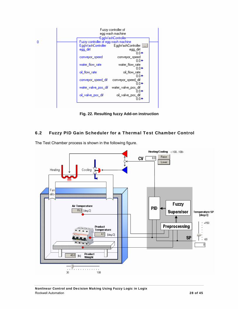
Fig. 22. Resulting fuzzy Add-on instruction
6.2 Fuzzy PID Gain Scheduler for a Thermal Test Chamber Control
The Test Chamber process is shown in the following figure.
Nonlinear Control and Decision Making Using Fuzzy Logic in Logix Rockwell Automation 28 of 45

The Test Chamber is used for thermal testing diverse products (e.g. electronic devices). The user sets a temperature set-point for the product inside the chamber. The range of temperature set-points is from -60 to +150 [deg C]. The controller must reach this temperature as soon as possible and maintain it until a new set-point is entered. Overshoot must be under 5% or 5 [deg.C] (whichever is smaller). When heating (control variable CV is positive <0, 100>), the controller manipulates the electric heating actuator. When cooling (CV is negative <-100, 0>) the controller manipulates the valve actuator that controls the flow rate of injected liquid nitrogen. The constantly running fan circulates air.
Standard PID control with a single setting of controller parameters does not satisfy control requirements because the process has very different operating characteristics, depending on actual operating conditions. The main issues:
• Process non-linearities
o Heating and cooling are two different physical processes
Heater can reach up to +1200 [deg C] while liquid nitrogen is -196 [deg C]
o Different products have different thermal characteristics such as
heat capacity
thermal conductivity
o Cooling effect varies with actual product temperature
e.g. product temperature is more sensitive to cooling when temperature is 150 [deg C] as opposed to when it is -50 [deg C]
• Significant transportation delay
o Delay between the control action and its effect on the product temperature
o Delay differs in heating and cooling modes
• Effect of external disturbances (not measured)
o Heat transfer from/to the ambient environment is a function of ambient temperature
o Heat transfer from the fan to air
Controller Design
One solution that satisfies the requirements in a wide range of operating conditions is a nonlinear PID controller with scheduled gains, using expert fuzzy rules based on actual operating conditions. The rules for gain scheduling are acquired from process analysis and experiments. When scheduling P gain under conditions that the control error E is not zero, we recommend using the PID controller with absolute form of the PID equation and avoiding the velocity form. Assume the control error E=0 and CV=0 and then the error changes about ∆E, velocity form of the PID will get CV = P1*∆E, now if we change P gain to P2 and error changes back to zero we get CV = P1*∆E-P2*∆E ≠ 0. So it is preferable to use standard PID instruction and avoid PIDE.
Nonlinear Control and Decision Making Using Fuzzy Logic in Logix Rockwell Automation 29 of 45

The following figure illustrates the structure of the control system.
PID ControllerPVSP
CV
Test Chamber Process
Product Temperature
Air Temperature
Heat/Cool Actuator
PGain
Preprocessing
ddt
Product Weight
DGainIGain
Feedforward∫
Postprocessing
Product Temperature Setpoint
+-
-+ddt
Fuzzy Gain Scheduler
ProductWeight
ProductTempSP
ProductTempError
ProductTempSpeed
AirProductTempDif
AirProductTempDifSpeed
PGain
IGain
DGain
FFChange
Nonlinear Multivariate ControllerLogix
The following signals will be used in the control system.
Inputs to the fuzzy gain scheduler: ¥ Product weight [lb] (Tag name: ProductWeight)
¥ Product temperature setpoint [deg C] (Tag name: ProductTempSP)
¥ Product temperature error (SP-temperature) [deg C] (Tag name: ProductTempError)
¥ Product temperature speed [deg C/s] (Tag name: ProductTempSpeed)
¥ Difference of air and product temperature [deg C] (Tag name: AirProductTempDif)
¥ Speed of the difference of air and product temperature [deg C/s] (Tag name: AirProductTempDifSpeed)
Outputs from the fuzzy gain scheduler: ¥ Proportional gain (Tag name: PGain)
¥ Integral gain (Tag name: PGain)
¥ Derivative gain (Tag name: PGain)
¥ Feedforward change (Tag name: FFChange)
Inputs to the PID controller: ¥ Product temperature set-point [deg C] (Tag name: ProductTempSP)
¥ Product temperature [deg C] (Tag name: ProductTemp)
Outputs from the PID controller: ¥ Control variable (Tag name: CV)
P,D gains scheduling rules
When the product weight is high (rules 5-8 ), then process response is generally slower, so we will apply higher P gain as opposed to when the product weight is low (rules 1-4). The rules 1 and 5 are applied when the product temperature is near the set-point, so the process is nearly settled
Nonlinear Control and Decision Making Using Fuzzy Logic in Logix Rockwell Automation 30 of 45

down. Rules 2 and 6 are activated when the temperature error is positive, so the process is in the heating state and appropriate P, D gains are applied. Rules 3, 4, 7 and 8 are activated in the cooling state. The process is much more sensitive to control variables during cooling and when the temperature is high, so lower P gain is applied (rules 3,7) as opposed to when the temperature is low (rules 4,8).
1. IF (ProductWeight IS low) AND (ProductTempError IS zero), THEN (PGain IS lw_steady)[1], (DGain IS lw_high)[1]
2. IF (ProductWeight IS low) AND ( (ProductTempError IS positive), THEN (PGain IS lw_heat)[1], (DGain IS lw_high)[1]
3. IF (ProductWeight IS low) AND (ProductTempSP IS high) AND (ProductTempError IS negative), THEN (PGain IS lw_cool_low)[1], (DGain IS lw_low)[1]
4. IF (ProductWeight IS low) AND (ProductTempSP IS low) AND (ProductTempError IS negative), THEN (PGain IS lw_cool_high)[1], (DGain IS lw_low)[1]
5. IF (ProductWeight IS high) AND (ProductTempError IS zero), THEN (PGain IS hw_steady)[1], (DGain IS hw_low)[1]
6. IF (ProductWeight IS high) AND ( (ProductTempError IS positive), THEN (PGain IS hw_heat)[1], (DGain IS hw_low)[1]
7. IF (ProductWeight IS high) AND (ProductTempSP IS high) AND (ProductTempError IS negative), THEN (PGain IS hw_cool_low)[1], (DGain IS hw_medium)[1]
8. IF (ProductWeight IS high) AND (ProductTempSP IS low) AND (ProductTempError IS negative), THEN (PGain IS hw_cool_high)[1], (DGain IS hw_high)[1]
I gain scheduling rules
To ensure zero steady-state error, an integrator is necessary. But constantly running an integrator causes large overshoot because of the significant transport delay in the process. To prevent the temperature from overshooting, the integrator is scheduled to run just when the temperature is nearly settled down (temperature speed is nearly zero). The higher the product weight, the higher I gain is applied.
1. IF (ProductWeight IS low) AND (ProductTempSpeed IS lw_zero), THEN (IGain IS lw_high)[1]
2. IF (ProductWeight IS low) AND (ProductTempSpeed IS NOT lw_zero), THEN (IGain IS zero)[1]
3. IF (ProductWeight IS high) AND (ProductTempSpeed IS hw_zero), THEN (IGain IS hw_high)[1]
4. IF (ProductWeight IS high) AND (ProductTempSpeed IS NOT hw_zero), THEN (IGain IS zero)[1]
Feedforward scheduling rules
When the product temperature is nearly settled down and the air temperature is sharply falling
Nonlinear Control and Decision Making Using Fuzzy Logic in Logix Rockwell Automation 31 of 45
(rising), we predict the product temperature will fall (rise) too. To prevent this, we will raise (lower) feedforward.
1.IF (ProductTempError IS NOT negative) AND (AirProductTempDif IS positive_medium) AND (ProductTempSpeed IS NOT positive) AND (AirProductTempDifSpeed IS very_negative), THEN (FFChange IS small_positive)[1]
2. IF (ProductTempError IS NOT positive) AND (AirProductTempDif IS negative_medium) AND (ProductTempSpeed IS NOT negative) AND (AirProductTempDifSpeed IS very_positive), THEN (FFChange IS small_negative)[1]
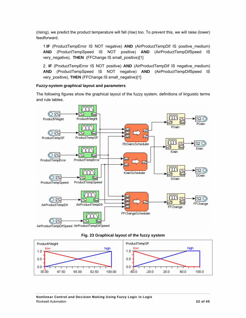
Fuzzy-system graphical layout and parameters
The following figures show the graphical layout of the fuzzy system, definitions of linguistic terms and rule tables.
Fig. 23 Graphical layout of the fuzzy system
Nonlinear Control and Decision Making Using Fuzzy Logic in Logix Rockwell Automation 32 of 45

Fig. 24 Definition of linguistic terms
Nonlinear Control and Decision Making Using Fuzzy Logic in Logix Rockwell Automation 33 of 45

Fig. 25 Rule table of the PDGainsScheduler rule block
Fig. 26 Rule table of the IGainScheduler rule block
Fig. 27 Rule table of the FFChange Scheduler rule block
6.3 Expert Diagnostic System for a Machine Illustrating Hierarchical Fuzzy Systems
Hierarchical fuzzy systems allow us to chain fuzzy rules so that conclusions of one rule-base can be used as conditions (premises) of another rule-base. So results of one of fuzzy inference are used as inputs to another.
The following example demonstrates part of a fuzzy expert diagnostic system that classifies
Nonlinear Control and Decision Making Using Fuzzy Logic in Logix Rockwell Automation 34 of 45
operating conditions of a machine. The fuzzy expert diagnostic system consists of the following variables.
Input variables:
• input_power (input power [kW])
• oil_temperature (oil temperature [deg C])
• vibration_level (vibration level [dB])
Output variable:
• motor_condition (diagnosis of the motor condition [-])
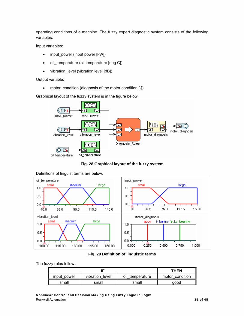
Graphical layout of the fuzzy system is in the figure below.
Fig. 28 Graphical layout of the fuzzy system
Definitions of linguist terms are below.
Fig. 29 Definition of linguistic terms
The fuzzy rules follow.
IF THEN input_power vibration_level oil_temperature motor_condition
small small small good
Nonlinear Control and Decision Making Using Fuzzy Logic in Logix Rockwell Automation 35 of 45

small medium small imbalance small large small imbalance large small small good large medium small good large large small imbalance small small medium good small medium medium faulty_bearing small large medium faulty_bearing large small medium good large medium medium good large large medium faulty_bearing small small large imbalance small medium large faulty_bearing small large large faulty_bearing large small large imbalance large medium large imbalance large large large faulty_bearing
As we want to select just one diagnosis of the motor, defuzzification method MOM is used.
When analyzing the rules we can conclude that the input linguistic variables “input_power” and “vibration_level” are logically associated with respect to motor condition. So the fuzzy system can be decomposed using an intermediate linguistic variable named “vibration_diagnosis.” That term is associated with the input linguistic variables “input_power” and “vibration_level” by means of the fuzzy rules below.
IF THEN Input_power Vibration_level vibration_diagnosis
small small acceptable small medium unacceptable small large unacceptable large small acceptable large medium acceptable large large unacceptable
The resulting motor condition can now be described by the intermediate variable “vibration diagnosis” and chaining rules as shown below.
IF THEN vibration_diagnosis oil_temperature motor_condition
acceptable small good unacceptable small imbalance acceptable medium good
unacceptable medium faulty_bearing acceptable large imbalance
unacceptable large faulty_bearing
Nonlinear Control and Decision Making Using Fuzzy Logic in Logix Rockwell Automation 36 of 45

Graphical layout of the resulting hierarchical fuzzy system is in the picture below.
Fig. 30 Hierarchical fuzzy system
As we can see, the decomposition results in a smaller number of rules (we saved 8 rules) and easier insight into fuzzy system function. So if possible, first find logically associated variables and then decompose fuzzy system.
FuzzyDesigner allows users not only to logically chain rules, as described above, but to chain whole fuzzy systems. This feature is demonstrated on the fuzzy system below.
Fig. 31 Chain of fuzzy systems
The resulting motor diagnosis is further processed (fuzzified) in the input linguistic variable “motor_condition” and used to generate suitable power control.
6.4 Fuzzy Supervised PI Controller of a Wet Blend Process
A fuzzy supervised PI controller of the temperature in wet blend food processing is shown in this example.
Process description
The technology of wet blend food processing consists of a wet blender with screw augers rotating in a constant speed, a dry mix feeder, a water sprinkler, and steam heating of the processed dry
Nonlinear Control and Decision Making Using Fuzzy Logic in Logix Rockwell Automation 37 of 45

mix/ water mixture as shown in the following figure.
The recipe of the thermal processing of the dry mix/water mixture defines the constant mass inflow of water, mass inflow of dry mixture of ingredients and specific temperature of the processed material, which should be kept constant. A minor tolerance is allowed. The technology is controlled typically by three loops – water inflow, dry mix feeding and the product temperature according to the recipe. Water control is not a problem and it is solved by the standard PI loop. The same solution is adopted for dry mix feeding. Both dry mix and water feeding are thus controlled well using a standard PID loop following the set-point given by the recipe.
On the contrary, design of the temperature control is not trivial and requires careful modeling and process analysis before the control algorithm is designed and implemented. The reasons: The process is highly nonlinear and the thermal processing requires that the measured temperature is stabilized under several disturbances that are caused by applying various recipes (ambient temperature, water flow rate, dry mix mass feed rate) and changing external conditions (ambient temperature). Another problem is caused by the significant time delay from the actuator, a steam servo valve, to the product temperature measured by the RTD sensor. So a single setting of controller parameters does not satisfy control requirements for the whole spectrum of applied recipes. Any attempts for using standard PID control were not successful due to effect of the disturbance variables and significant transportation delay between the control action and its effect on temperature. The operator, however, was able to maintain the temperature within the limit, so there had to be logic that could allow a switch into automatic mode.
One of the solutions that satisfies the requirements in wide range of operating conditions is a nonlinear PI controller with scheduled gains, nonlinear feedforward (bias) action based on the desired temperature, and a conditionally running integral term. Design and tuning of this nonlinear PI controller was based on a detailed analysis of static and dynamic characteristics of the
Nonlinear Control and Decision Making Using Fuzzy Logic in Logix Rockwell Automation 38 of 45

process.
The actuator is a steam-control valve that had been manipulated by the operator before fuzzy logic took over.
Process signals
The control system for the process consists of the following signals:
Process variables (inputs to the controller):
Product (blended mix) temperature [deg F] (signal name: Temperature)
Product temperature set-point [deg F] (signal name: Setpoint)
Product temperature error change d(Setpoint-Temperature)/Ts [deg F/s] (signal name: Error_Change)
Product temperature error (Setpoint-Temperature) [deg F] (signal name: Error)
Control variables (outputs from the controller):
Steam-valve control [0-100] (signal name: Valve_Control). The signal is used as a valve-position set-point for the steam-valve drive actuator.
The other inputs to the process specified by the recipe – such as dry ingredients feed-rate set-point, water-flow-rate set-point and ambient temperature – are considered disturbances to our control system.
Description of rules for PI controller scheduling
The structure of the PI controller is as follows:
( ) BiasdtErrorKiErrorKCV +⋅⋅+= ∫
where CV is the control variable Valve_Control and Error = Setpoint Temperature
K gain scheduling
Because the temperature is more sensitive to the control variable when both the CV and temperature are low versus high, we will use the following rules for scheduling the K gain.
1. IF (Setpoint IS low), THEN (K IS small)[1]
2. IF (Setpoint IS large), THEN (K IS large)[1]
So if the set-point is low, a low K gain is used to prevent the controller from having a large overshoot and/or oscillation. Conversely, if the set-point is high, a large K gain is used to prevent the controller from controlling too slowly.
Ki gain scheduling
Due to the significant transportation delay between the control action and its effect on the temperature, integration should be stopped early if the temperature approaches the setpoint too quickly and if the temperature is already near the set-point. This prevents the controller from having a large overshoot.
Nonlinear Control and Decision Making Using Fuzzy Logic in Logix Rockwell Automation 39 of 45

1. IF (Error_Change IS small) AND (Error IS small), THEN (Ki IS positive)[1]
2. IF (Error_Change IS NOT small) AND (Error IS small), THEN (Ki IS zero)[1]
3. IF (Error_Change IS medium) AND (Error IS NOT small), THEN (Ki IS positive)[1]
4. IF (Error_Change IS NOT medium) AND (Error IS NOT small), THEN (Ki IS zero)[1]
Bias term scheduling
A nonlinear feedforward static characteristic of the controller is described by the following rules:
1. IF (Setpoint IS zero), THEN (Bias IS B_3)[1]
2. IF (Setpoint IS very_small), THEN (Bias IS B_4)[1]
3. IF (Setpoint IS small), THEN (Bias IS B_7)[1]
4. IF (Setpoint IS medium), THEN (Bias IS B_10)[1]
5. IF (Setpoint IS big), THEN (Bias IS B_18)[1]
6. IF (Setpoint IS very_big), THEN (Bias IS B_60)[1]
7. IF (Setpoint IS extra_big), THEN (Bias IS B_100)[1]
8. IF (Setpoint IS above_all), THEN (Bias IS B_100)[1]
6.5 Fuzzy Supervised State Feedback Controller of an Inverted Pendulum and Crane System
A fuzzy supervised state feedback controller realized by a Takagi-Sugeno fuzzy system is used to control crane and inverted pendulum system. The dynamic system is operated in two different operating points, in each one the system can be well controlled by a local state feedback. In order to smoothly move between theses two points the Takagi-Sugeno fuzzy system is used to bumplessly switch between the two local controllers.
Process description
This example demonstrates a classic control problem – to control an inverted pendulum or a crane. This process is also often used as a benchmark problem for different control schemes. The process is non linear and unstable with one output signal and several input signals. In the inverted pendulum control problem, the aim is to move the cart to the desired position and to balance a pendulum without the pendulum falling. In the crane control problem, the aim is to move the cart to the desired position and to reduce the sway of the pendulum (which can represent for example some load which has to be transported to a target point) to almost zero. The principle scheme of both control problems is shown below.
Nonlinear Control and Decision Making Using Fuzzy Logic in Logix Rockwell Automation 40 of 45

FuzzyController
FuzzyController
SpeedController
Cart speed setpoint
d/dt
d/dt
Actual pendulum angle 2
Cart positionsetpointPendulumangle setpoint
Actual pendulum angle 1
Cart position
0
π Inverted pendulumcontrol problem
Crane controlproblem
x (cart position)
Process signals
The control system for the process consists of the following signals
Process variables (inputs to the controller):
actual cart position [m] (signal name: ‘x’)
cart speed [m/s] (signal name: ‘dx’)
cart position setpoint [m] (signal name: ‘x_SP’)
actual angle of the pendulum pole measured from the bottom (0) position [rad] (signal name: ‘phi_0’)
setpoint for the angle of the pendulum pole [rad] (signal name: ‘phi_SP’), possible value is either 0 (for the crane control mode) or π (for the inverted pendulum control mode).
angular speed of the pendulum pole [rad/s] (signal name: ‘dphi’)
actual angle of the pendulum pole measured from the upper (π) position [rad] (signal name: ‘phi_pi’)
Control variables (outputs from the controller):
cart speed setpoint control variable (signal name: ‘CV’). The signal is used as a speed setpoint for the cart drive actuator.
Description of the controller
From the analysis of the system an analytical model of the system in the form of nonlinear differential equations was created. The nonlinear model was linearized in two operating points (OP):
OP1: bottom (0) pole position (crane control mode) OP2: upper (π) pole position (inverted pendulum control mode)
For each operating point a linear state feedback controller was designed using standard pole placement method. The structure of a linear state feedback controller is as follows.
Nonlinear Control and Decision Making Using Fuzzy Logic in Logix Rockwell Automation 41 of 45
CV = K*state’ = K(1)*state(1) + K(2)*state(2)+ … + K(n)*state(n)
where CV is a control variable, K is a vector of state feedback gains, state is a vector of state variables. K(i) is a state feedback gain corresponding to the state(i) state variable. Particular state feedback controllers K_0 and K_pi for the respective operating points are as follows.
OP1: CV = -4.4037*(x – x_SP) - 4.5046*dx + 15.4325*phi_O - 3.7569* dphi = K_0*state’ OP2: CV = 4.4037*(x – x_SP) + 6.5046*dx - 50.5675*phi_pi - 12.7569* dphi = K_pi*state’
Since these controllers are working correctly only if the system state is near to their corresponding operating point, it is necessary to smoothly switch between these controllers according to current system state. Additionally, it is necessary to apply such a control action that will get the system state near to a desired operating point if it is far from it. For such a task, when we need a smooth switch between linear functions based on expert rules, it is very effective to use a Takagi-Sugeno fuzzy system. The Takagi-Sugeno fuzzy system can be also viewed as a rule-based scheduler of the coefficients (gains) of the linear function (controller).
Assume that the system state is composed of the following signals.
state = [x, dx, x_SP, phi_O, dphi, phi_SP, phi_pi]’
The rules of the Takgi-Sugeno fuzzy controller are the following.
1. IF (phi_0 IS small) AND (phi_SP IS zero), THEN (CV = K_0*state)[1]
2. IF (phi_0 IS NOT small) AND (phi_SP IS zero), THEN (CV = no_action)[1]
3. IF (phi_SP IS zero) AND (dphi IS very_small) AND (phi_pi IS zero), THEN (CV = change_position)[1]
4. IF (phi_SP IS pi) AND (phi_pi IS NOT low), THEN (CV = no_action)[1]
5. IF (phi_0 IS very_small) AND (phi_SP IS pi) AND (dphi IS negative), THEN (CV = move_right)[1]
6. IF (phi_0 IS very_small) AND (phi_SP IS pi) AND (dphi IS positive), THEN (CV = move_left)[1]
7. IF (phi_0 IS near_zero) AND (phi_SP IS pi) AND (dphi IS very_small), THEN (CV = change_position)[1]
8. IF (phi_SP IS pi) AND (phi_pi IS low), THEN (CV = K_pi*state)[1]
The rules 1 and 8 simply state that if the system state is near to OP1 or OP2, then apply the corresponding state feedback gain K_0 or K_pi. Rule 3 states that the cart will be moved to the right to cause the pole to fall down if it is inverted and the desired operating point is OP1. Rules 5, 6 and 7 are applied to get the pole to the desired inverted position, OP2, if the pole is still at the bottom position. Rules 2 and 4 state that no control action is to be applied if the system state is far from the desired state, thereby covering all the other cases.
Nonlinear Control and Decision Making Using Fuzzy Logic in Logix Rockwell Automation 42 of 45

xdxphi_Odphiphi_pi
Processx_SPphi_SP
setpoints
state
K_0K_0
change_positionchange_position
no_actionno_action
move_leftmove_left
move_rightmove_right
K_piK_pi
Rule base
CV
Output Takagi-Sugeno variable description
An output Takagi-Sugeno (OTS) variable in FuzzyDesigner is defined by inputs and terms. The inputs are specified by signals connected to its pins. A term type is either LINEAR or CONSTANT. For example, assume that we want to create the following rule-based scheduler of linear controllers:
1. IF condition1, THEN Y = K0 + K1*X1 + K2*X2
2. IF condition2, THEN Y = G0 + G1*X1 + G2*X2
3. IF condition3, THEN Y = C0
Then we have to create corresponding OTS variable in the following way: 1. Create a new OTS variable with 2 pins connected to inputs X1 and X2. 2. Create the following 3 terms
o LINEAR term K with parameters = K0 K1 K2 o LINEAR term G with parameters = G0 G1 G2 o CONSTANT term C with parameters = C0
In the pendulum application, the inputs to the OTS variable correspond to signals in the state vector defined above.
Parameters of conclusion functions:
Term Name Term Type Parameters
no_action LINEAR 0 0.01 0 0 0 0 0 0
move_left CONSTANT -10
Nonlinear Control and Decision Making Using Fuzzy Logic in Logix Rockwell Automation 43 of 45

move_right CONSTANT 10
change_position CONSTANT 5
K_pi LINEAR 0 4.4037 6.5046 -4.4037 0 -12.7569 0 -50.5675
K_0 LINEAR 0 -4.4037 -4.5046 4.4037 15.4325 -3.7569 0 0
Graphical layout of the fuzzy system and definitions of linguistic terms are below
Fig. 32 Graphical layout of the fuzzy system
Fig. 33 Defined linguistic variables and their terms
Nonlinear Control and Decision Making Using Fuzzy Logic in Logix Rockwell Automation 44 of 45

7. References for further reading Chiu S.: Developing Commercial Applications of Intelligent Control. IEEE Control Systems Magazine, Vol. 17, No. 2, 1997, s. 94–97. Driankov D., Hellendoorn H., Reinfrank M.: An Introduction to Fuzzy Control. Springer-Verlag, Berlin 1993. Kruse R., Gebhardt J. E., Frank K.: Foundations of Fuzzy Systems. John Wiley & Sons, 1996. Sugeno M.: Industrial Applications of Fuzzy Control. Elsevier Science Ltd, 1985. Verbruggen H. B., Zimmermann H.-J., Babuška R. (eds): Fuzzy Algorithms for Control. Kluwer
Academic Publishers, Dordrecht 1999. Wang L.-X.: A course in fuzzy systems and control. Prentice Hall, 1997.
Nonlinear Control and Decision Making Using Fuzzy Logic in Logix Rockwell Automation 45 of 45


Publication 9324-WP006A-EN-P – August 2007 Copyright ©2007 Rockwell Automation, Inc. All Rights Reserved. Printed in USA.