Embed Size (px)
Citation preview

1/27 © D J Inman
Nonlinear Considerations in
Energy Harvesting
Daniel J. Inman
Alper Erturk*
Amin Karami Center for Intelligent Material Systems and Structures
Virginia Tech
Blacksburg, VA 24061, USA
[email protected] www.cimss.vt.edu
and
Institute for Smart Technologies
University of Bristol
Bristol, BS* 1TR UK
*Woodruff School of Mechanical Engineering, Georgia Tech

2/27 © D J Inman
Two key issues in energy harvesting can be
solved by introducing nonlinear effects
For identical inputs
to a linear system
and a nonlinear
system ….
… a drastically improved
voltage results which is
broadband and of larger
magnitude.

3/27 © D J Inman
Voltage FRFs (broadband configuration)
Piezoelectric bimorphs
Electromagnetic shaker
Accelerometer
Comparison of the voltage FRFs Voltage FRFs (single cantilever)
Not an outstanding design in terms of the power density…
There are many conventional ways of making broadband energy harvesters…
Others use electromagnetic transduction (Beeby, et al)

4/27 © D J Inman
Hardening stiffness of the monostable Duffing oscillator has been investigated by others to increase the bandwidth of operation.
Mann and Sims (2009)
Piezoelectric energy harvester with cubic stiffness
The high-energy branch can be lost due to the shunt damping effect of the electrical load (weak nonlinearity).

5/27 © D J Inman
Here We Examine Using a Bistable Piezomagnetoelastic Beam
Magnets added near the tip of a cantilever introduce nonlinearity
(Moon and Holmes, 1979)

6/27 © D J Inman
Limit Cycle Oscillations for Broad Band
Harvesting
A magnetic field causes the equation of motion of the
harvesting piezoelectric cantilever to be nonlinear
Spacing of the magnets results in:
5 equilibrium (3 stable)
3 equilibrium (2 stable)
1 equilibrium (1 sable)
Limit cycle oscillation is the possible producing large
amplitude periodic response over a range of input
frequencies
x + 2zx -1
2x 1- x2( ) - cv = f cosWt
v + lv +k x = 0

7/27 © D J Inman
First the strange attractor (Moon and Holmes, 1979) is captured in the chaotic response of the piezomagnetoelastic configuration.
The piezomagnetoelastic energy harvester configuration has been investigated theoretically and experimentally.
Theory Experiment
0.35g (RMS) at 8 Hz
[movie]
8/27 © D J Inman
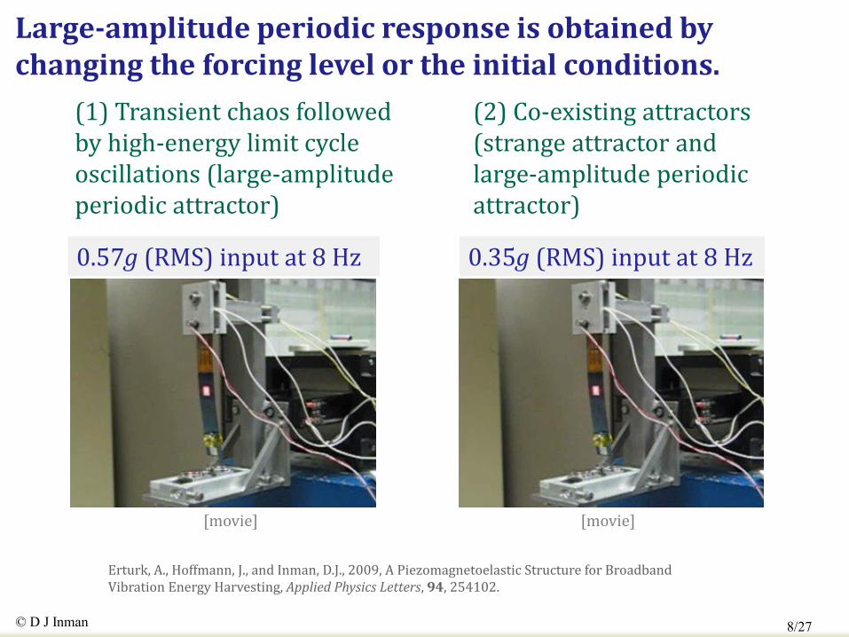
0.57g (RMS) input at 8 Hz 0.35g (RMS) input at 8 Hz
[movie] [movie]
(1) Transient chaos followed by high-energy limit cycle oscillations (large-amplitude periodic attractor)
(2) Co-existing attractors (strange attractor and large-amplitude periodic attractor)
Erturk, A., Hoffmann, J., and Inman, D.J., 2009, A Piezomagnetoelastic Structure for Broadband Vibration Energy Harvesting, Applied Physics Letters, 94, 254102.
Large-amplitude periodic response is obtained by changing the forcing level or the initial conditions.

9/27 © D J Inman
Theoretical simulations show the presence of these high-energy orbits at several frequencies.
Piezoelastic cantilever Piezomagnetoelastic cantilever

10/27 © D J Inman
Experimental verification of the broadband high-energy orbits in the piezomagnetoelastic configuration
0.35g (RMS) at 8 Hz
0.35g (RMS) at 6 Hz
[movie]
[movie]

11/27 © D J Inman
Large-amplitude response of the piezomagnetoelastic energy harvester yields an order of magnitude larger power output over a range of frequencies.
Base acceleration (input) Open-circuit voltage (output)
Po
wer

12/27 © D J Inman
Power Output Comparison of Linear vs
Nonlinear
Excitation
Frequency
5 Hz 6 Hz 7 Hz 8 Hz
Piezo-
Magneto-
Elastic
1.57 mW 2.33 mW 3.54 mW 8.54 mW
Piezo-elastic 0.10 mW 0.31 mW 8.23 mW 0.46 mW
Linear Resonance
Note that at linear resonance the linear system will always win,
however it is narrow band and falls off quickly away
from resonance and that the nonlinear has higher values overall

13/27 © D J Inman
Bistable piezo-carbon-fiber-epoxy plate
Courtesy of the Bristol Composites Group

14/27 © D J Inman
A bistable carbon-fiber-epoxy plate exhibits similar nonlinear dynamics (no external magnets required).
The plate is clamped to a seismic shaker from its center point.
State 1 State 2
Linear FRFs around each stable state
The stable equilibrium positions are not symmetric with respect to the unstable one.
Arrieta, A.F., Hagedorn, P., Erturk, A., and Inman, D.J., 2010, A Piezoelectric Bistable Plate for Nonlinear Broadband Energy Harvesting, Applied Physics Letters, 97, 104102.

15/27 © D J Inman
Various nonlinear phenomena can be observed in the bistable plate configuration.
Chaos (12.5 Hz)
High-energy LCO (8.6 Hz) Intermittent chaos (9.8 Hz)
Subharmonic resonance (20.2 Hz)
[movie] [movie]
[movie] [movie]

16/27 © D J Inman
Forward sweep Backward sweep Power curves
Various nonlinear phenomena can be observed in the bistable plate configuration.
LCO
Chaos
Chaos

17/27 © D J Inman
Large-amplitude oscillations generate very high power output over a range of frequencies.
Average power vs. Frequency
Average power vs. Load resistance
(98.5 kohm)

18/27 © D J Inman
Nonlinear Hybrid Harvester
Coil
Piezo
element
Tip magnet
Electromagnetic
Harvesting High current low
voltage
Piezoelectric
Harvesting: High voltage low
current
Coil
R1
R2
z
x

19/27 © D J Inman
Mono-Stable : Magnet Spacing
4 6 8 10 12 140
0.05
0.1
0.15
0.2
0.25
0.3
0.35
R1=100k , R
2=5 , a
b=1.47, legend: (mm)
Frequency (Hz)
Tip
ve
l/ B
ase
acce
l (1
/S)
37
45
58
4 6 8 10 12 140
0.2
0.4
0.6
0.8
1
1.2
1.4x 10
-3R
1=100k , R
2=5 , a
b=1.47, legend: (mm)
Frequency (Hz)
PZ
T p
ow
er/
Ba
se
acce
l2 (
Kg
.S)
37
45
58
4 6 8 10 12 140
1
2
3
4
5
6
7
8x 10
-5 R1=100k , R
2=5 , a
b=1.47, legend: (mm)
Frequency (Hz)
E.M
. p
ow
er/
Ba
se
acce
l2 (
Kg
.S)
37
45
58
Tip Velocity
PZT Power Electro/Mag Power

20/27 © D J Inman
Bi-Stable : Base Acceleration
Tip Velocity
PZT Power Electro/Mag Power
-0.04 -0.02 0 0.02 0.04-1
0
1
1
2
3
4
5
6
ba
se
acce
l. (
m.s
-2)
xt (m)
vt (m.s
-1)
1 2 3 4 5 610
-5
10-4
10-3
10-2
base accel. (m.s-2
)
PZ
T p
ow
er
(Wa
tt)
small amplitude
Limit Cycle
chaos
1 2 3 4 5 610
-7
10-6
10-5
10-4
10-3
base accel. (m.s-2
)
EM
po
we
r (W
att)
small amplitude
Limit Cycle
chaos

21/27 © D J Inman
3-span steel girder bridge (08/18/09 - Roanoke)
Approximation as a persistent single harmonic (0.05g at 7.7 Hz)
Acceleration signal measured on the bridge
Acceleration data of the bridge has been simplified to a harmonic function for simulations in the lab.
Seismic shaker
Accelerometer
Piezoelectric and electromagnetic generators
Acceleration measured on the shaker
Experimental setup

22/27 © D J Inman
Piezoelectric and electromagnetic power outputs have been measured for an acceleration input of 0.05g (RMS: 0.035g) at 7.7 Hz.
Piezoceramic patches
Accelerometer
Seismic shaker
Rare earth magnets
Combined piezoelectric-electromagnetic generator configuration
Coil
Electromagnetic part : 0.22 V for 82 ohms = 0.6 mW (per coil) Piezoelectric part : 11.2 V for 470 kohms = 0.3 mW
Power output of a single generator (for 0.05g) = 0.9 mW

23/27 © D J Inman
Increased base acceleration amplitude results in a larger power output. (0.1g, RMS: 0.07g at 7.7 Hz yields 2.7 mW).
Electromagnetic part : 0.42 V for 100ohms = 1.8 mW (from a single coil) Piezoelectric part : 21 V for 470 kohms = 0.94 mW
Power output of a single generator (for 0.1g) = 2.7 mW
[click on the movie]

24/27 © D J Inman
Total damping vs. Airflow speed
Tip displacement
Electrical power
Is harvesting of flow through wing vibration possible?
At 9.23 m/s, 10.7 mW harvested
AND
The corresponding shunt effect
increased the flutter speed by 5.5%
Just a linear analysis for now but LCO does occur in aircraft

25/27 © D J Inman
Summary and conclusions
Bistable beam and plate configurations have been discussed for broadband energy harvesting.
The beam configuration requires magnets for bistability whereas the plate configuration is bistable due to the laminate characteristics.
The design problem is to achieve persistent snap through and nonlinear phenomena for the given excitation amplitude and frequency range.
Combined E/M and PZT is promising for charging batteries

26/27 © D J Inman
Some Funded Projects In the US
Center for Energy Harvesting Materials and Systems (National Science
Foundation/Industry program)
ITT: new lead free piezoelectric materials
UTRC: building applications (running infrastructure sensors
SAIC: submerged river sensors (flow harvesting)
Texas Instruments: TBA
Physical Acoustics Corporation: Harvesting for running AE sensors
Texas MicroPower: MEMs Zigzag harvester
National Institute for Standards and Testing
50 million USD in harvesting and monitoring of Bridges
Air Force Office of Scientific Research
6 million USD for harvesting in UAVs
27/27 © D J Inman
Air Force Office of Scientific Research grants monitored by Dr. ”Les” B. L. Lee
- F 9550-06-1-0326: “Energy Harvesting and Storage Systems for Future Air Force Vehicles”
- F 9550-09-1-0625: “Simultaneous Vibration Suppression and Energy Harvesting”
Acknowledgements
Thank you!.. Questions?
Shameless, Self Serving References Priya, S. and Inman, D. J., Editors, 2008, Energy Harvesting Technologies, Springer
Science+Business Media, Inc., Norwell, MA, 517 pp.
Erturk, A. and Inman, D. J., 2011, Piezoelectric Energy Harvesting, John Wiley &
Sons, Ltd.
National Science Foundation Center for Energy Harvesting Materials and Systems
http://cehms.mse.vt.edu