Embed Size (px)
Citation preview

Nonlinear and Time-Dependent Aerodynamics:
Implications for Testing and Flight Mechanics Analysis
Jerry E. JenkinsVoluntary Emeritus Corps
AFRL Wright-Patterson AFB, OH
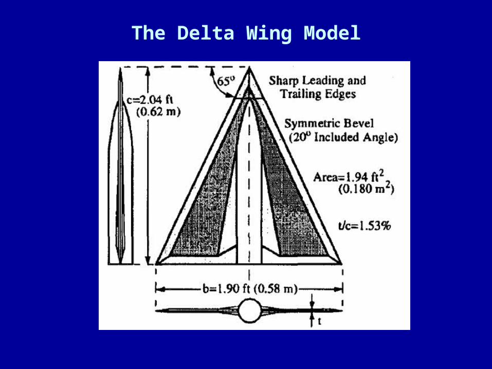
The Delta Wing Model
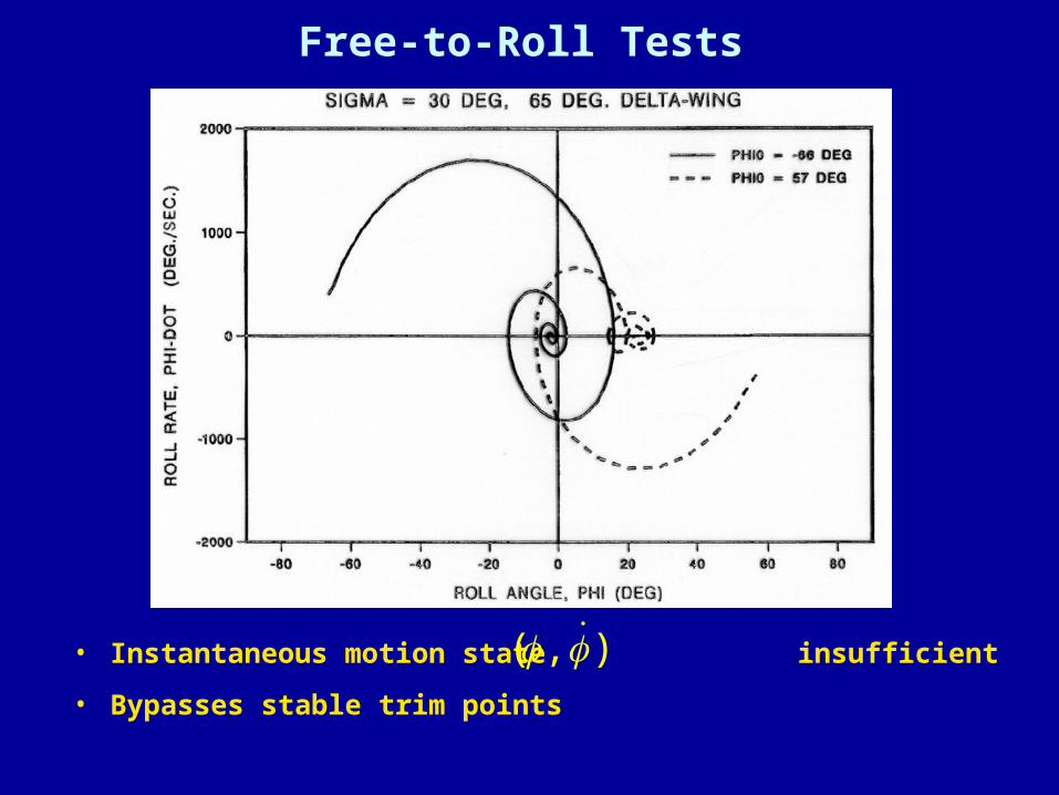
Free-to-Roll Tests
• Instantaneous motion state insufficient
• Bypasses stable trim points
( , )

Nonlinear & Unsteady Aero Characteristics: 65° Delta Wing
AIAA-97-0742
• Free-to-Roll tests perplexing results– Aerodynamic responses at moderate angles of attack
• Not determined by instantaneous motion state • Highly dependent on motion history

Nonlinear & Unsteady Aero Characteristics: 65° Delta Wing
AIAA-97-0742
• Free-to-Roll tests perplexing results– Aerodynamic responses at moderate angles of attack
• Often not determined by instantaneous motion state • Highly dependent on motion history
• Viscous effects superimposed on potential flow– L. E. Vortex system structure – Vortex breakdown dynamics

Nonlinear & Unsteady Aero Characteristics: 65° Delta Wing
AIAA-97-0742
Flow Structure
• The steady-state flow-field can become unstable– At some flight conditions (Critical States)
– Bifurcations in static force and moment characteristics

0.020
0.010
Ro
llin
g-M
om
ent
Co
effi
cien
t
5
Critical StateRegion I
= 30 o
Side-slip Angle - deg4
Region II
Critical State
0.025
0.015
0.005
0.000
Critical State
10 15 20
3 5 6 7 8 9
Region III Region IV
Critical State
Roll Angle - deg
Critical States

Flow Structure & Bifurcations
Left Wing
25
20
15
10
5
0
-5
Leeward
W indward
Critical S tates
Ro
ll A
ng
le -
de
g.
?
Concentrated Vortex - Secondary and Tertiary Attached
Concentrated Vortex - Secondary Attached Tertiary Lifts O ff
Concentrated Vortex - Secondary & Tertiary L ift O ff
Breakdown over P lanformBurst Point M oves Tow ard T.E . w ith Increasing Roll Angle
Region I
Region II

Flow Structure & Bifurcations
Right Wing
25
20
15
10
5
0
-5
W indw ard
Leew ard
C ritical S tates
Ro
ll A
ng
le -
de
g.
?
R everse Flow - S ingle Lift-O ff of Sw irling Flow Forw ardSeperation at T.E ., Reattachm ent Point N ear W ingtip
R everse Flow - S ingle Lift-O ff Point for Sw irling FlowB reakdow n Near Apex
B reakdow n over P lanformB urst Point M oves Tow ard Apex w ith Increasing Roll Angle
R egion I
R egion II
Nonlinear & Unsteady Aero Characteristics: 65° Delta Wing
AIAA-97-0742
Flow Structure
• The steady-state flow-field can become unstable– At some flight conditions (Critical States)
– Bifurcations in static force and moment characteristics
• Must transition to a new stable state when perturbed– Can require a considerable amount of time
– Static tests give us no clue as to how long

Nonlinear & Unsteady Aero Characteristics: 65° Delta Wing
AIAA-97-0742
Flow Dynamics
• Flow processes acting on at least three time scales– Transitions between equilibrium states – Potential flow phenomena – Vortex breakdown movement in response to the motion

Ramp Across a Critical State65o Delta Wing
Critical StateEncounter
Critical StateEncounter

Attached and Vortical Flow Contributions
Ramp and Hold
Potential Flow
0.020
0.010
0.000
-0.010
Rol
ling-
Mom
ent C
oeff
icie
nt
Roll Angle - deg-10 -5 0 5 10
Critical StateCritical State
Region I
Region II
Critical State
= 30 o
Side-slip Angle - deg
-5 -4 -3 -2 -1 0 1 2 3 4 5
Can isolate CS transients including motion history

No Critical State Encounter No Critical State Encounter
Critical State EncounterCritical State Encounter
( )Deg.
( )Deg. ( )Deg.
( )Deg.
static static
staticstatic
f = 7.7 Hz
f = 7.7 Hzf = 7.7 Hz
f = 7.7 Hz
f = 1.1 Hzf = 1.1 Hz
f = 1.1 Hzf = 1.1 Hz
Rolli
ng M
omen
t Co
effic
ient
- Cl
Rolli
ng M
omen
t Co
effic
ient
- Cl
Pitc
hing
Mom
ent C
oeffi
cien
t -
Cm
Pitc
hing
Mom
ent C
oeffi
cien
t -
Cm
-6 -4 -2 0 42 6 -6 -4 -2 0 42 6
-3 -1 1 3 75 9 -3 -1 1 3 75 9
Harmonic Motion With and Without Critical State Encounters
Rolling Moment Pitching Moment
k = 0.02 & 0.14

Harmonic Motion With and Without Critical State Encounters
Rolling Moment Pitching Moment
k = 0.02 & 0.14
No Critical State Encounter No Critical State Encounter
Critical State EncounterCritical State Encounter
( )Deg.
( )Deg. ( )Deg.
( )Deg.
static static
staticstatic
f = 7.7 Hz
f = 7.7 Hzf = 7.7 Hz
f = 7.7 Hz
f = 1.1 Hzf = 1.1 Hz
f = 1.1 Hzf = 1.1 Hz
Rolli
ng M
omen
t Co
effic
ient
- Cl
Rolli
ng M
omen
t Co
effic
ient
- Cl
Pitc
hing
Mom
ent C
oeffi
cien
t -
Cm
Pitc
hing
Mom
ent C
oeffi
cien
t -
Cm
-6 -4 -2 0 42 6 -6 -4 -2 0 42 6
-3 -1 1 3 75 9 -3 -1 1 3 75 9

Static Nonlinearities - AIAA 2004-5275
Region 1 2 3
4
Region 5

Multiple Time Scales in Linear RegionAIAA 2004-5275
• Slow responses cannot keep up with rapid motions

Broadband Input
• Allwine, et. al., “Nonlinear Modeling of Unsteady Aerodynamics at High Angle of Attack,” AIAA 2004-5275

Multiple Time Scales (F-16XL)AIAA 2001-4016
• Variation of in-phase & out-of-phase components
Lift-Curve slope
Lift due to pitch rate
Reduced freq.
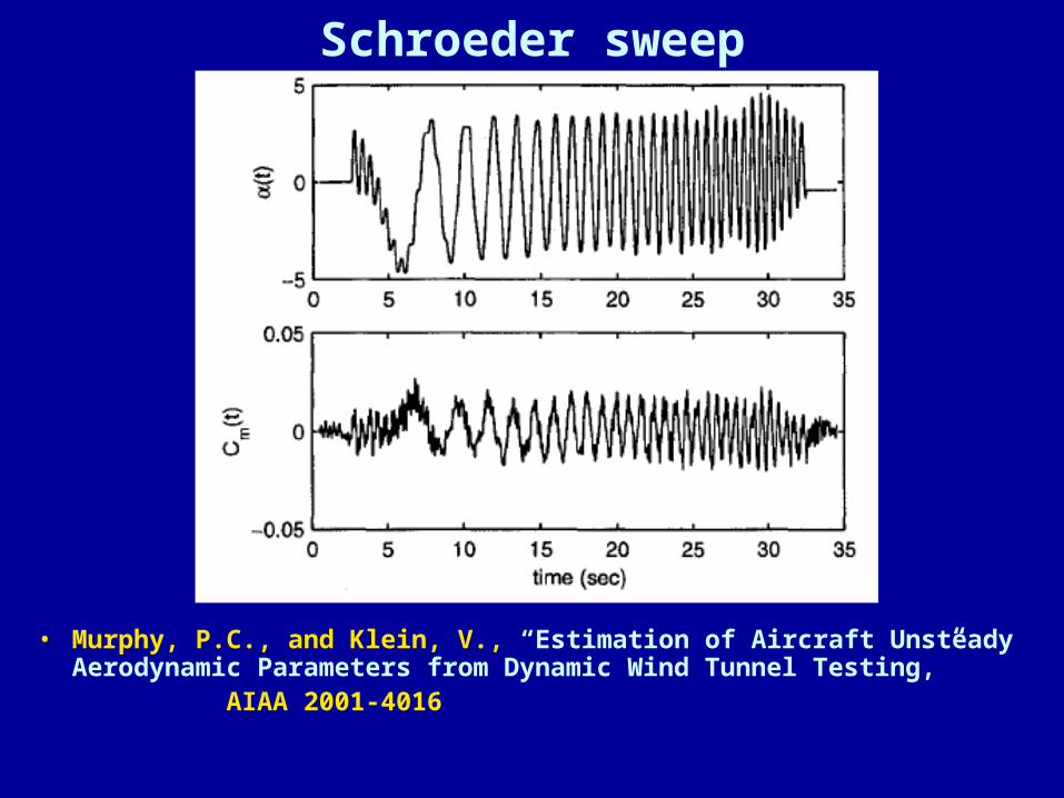
Schroeder sweep
• Murphy, P.C., and Klein, V., “Estimation of Aircraft Unsteady Aerodynamic Parameters from Dynamic Wind Tunnel Testing,”
AIAA 2001-4016

Langley Fighter Model

Roll-Damping “Derivative”AIAA-2004-5273

Nonlinear & Unsteady Aero Characteristics: Summary
• Free-to-Roll tests difficult to explain results– Aerodynamic responses at moderate angles of attack
• Often not determined by instantaneous motion state • Highly dependent on motion history
• Traced to leading edge vortex system dynamics– Vortex system structure – Vortex breakdown phenomenon
• Response characteristics not unique to delta wings– Static discontinuities, i.e. flow-field instabilities– Multiple time scales

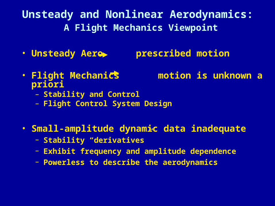
Unsteady and Nonlinear Aerodynamics: A Flight Mechanics Viewpoint
• Unsteady Aero prescribed motion
• Flight Mechanics motion is unknown a priori – Stability and Control– Flight Control System Design
Unsteady and Nonlinear Aerodynamics: A Flight Mechanics Viewpoint
• Unsteady Aero prescribed motion
• Flight Mechanics motion is unknown a priori – Stability and Control– Flight Control System Design
• Small-amplitude dynamic data inadequate– Stability “derivatives” – Exhibit frequency and amplitude dependence – Powerless to describe the aerodynamics
• Need math models for aerodynamics– Applicable to arbitrary motions– Functions of the translational and rotational DOF

Nonlinear & Unsteady Aero Characteristics:AIAA-97-0742
AIAA-2001-4016AIAA-2004-5273
• Results were for single DOF motions in wind tunnel
• Understanding requires that we – acknowledge the existence of multiple time scales – Consider the individual effects of translation and rotation – Include lags present in both responses

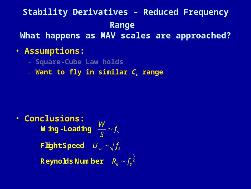
Stability Derivatives – Reduced Frequency Range What happens as MAV scales are approached?
• Assumptions:– Square-Cube Law holds

Vehicle Inertia Variation with Mass
3sm f 5and yy sI f
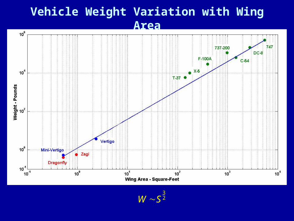
Vehicle Weight Variation with Wing Area
32W S
Stability Derivatives – Reduced Frequency Range What happens as MAV scales are approached?
• Assumptions:– Square-Cube Law holds
– Want to fly in similar CL range
• Conclusions:
32
s
s
e s
Wf
S
U f
R f
Wing- Loading
Flight Speed
Reynolds Number

Stability Derivatives – Reduced Frequency Range What happens as MAV scales are approached?
• Assumptions:– Square-Cube Law holds
– Want to fly in similar CL range
– Hold non-dimensional derivatives constant
• i.e. ignore Re effects
• Conclusions:
sp
sp
1
2
sf
c
U
Short - period frequency (damping ratio unchanged)
Reduced frequency unchanged

Stability Derivatives – Reduced Frequency Range What happens as MAV scales are approached?
• Consequences:– Magnitude of atmospheric disturbances do not scale
• Relative angular disturbances,
– Responses to disturbances up to not attenuated• Control system rates must increase
– Sensor sampling rates– Servo response times
– Aerodynamic effects• Convective time lags unaltered• Separated, vortex dominated flows ( low )
sp
1
sf
eR

Static Test Recommendations
• Closely spaced static data– Critical state detection
• Examine all components of the force and moment– Critical States are flow field events
• Make sweeps should in both directions – Hysteresis detection– Another indication of critical states
Dynamic Test Recommendations• Structure dynamic tests based on static test results

Dynamic Test Recommendations• Structure dynamic tests based on static test results
• Filtering (except anti-aliasing) should not be used– Ensemble averaging recommended

Dynamic Test Recommendations• Structure dynamic tests based on static test results
• Filtering (except anti-aliasing) should not be used– Ensemble averaging recommended
• Record the complete response– potential nonlinear effects -- Linearize off line

Dynamic Test Recommendations• Structure dynamic tests based on static test results
• Filtering (except anti-aliasing) should not be used– Ensemble averaging recommended
• Record the complete response– potential nonlinear effects -- Linearize off line
• Cover wide range reduced frequencies – Try to saturate the viscous effects – Extract both "static" and dynamic stability derivatives– Frequency dependence multiple time scales

Linear Aero Model from Broadband Data AIAA 2004-5275
• Linear system ID works quite well

Dynamic Test Recommendations• Structure dynamic tests based on static test results
• Filtering (except anti-aliasing) should not be used– Ensemble averaging recommended
• Record the complete response– potential nonlinear effects -- Linearize off line
• Cover wide range reduced frequencies – Try to saturate the viscous effects – Extract both "static" and dynamic stability derivatives– Frequency dependence multiple time scales
• Ramp and hold motions invaluable– Isolate critical state transients– Provide quantitative measures for response times– Examine history effects. – Consider other types of "motion and hold" experiments

Ramp-Between-Harmonics

Nonlinear Model Constructed from SSM’s AIAA 2004-5275

Nonlinear Model Constructed from SSM’s AIAA 2004-5275

Nonlinear Model Constructed from SSM’s AIAA 2004-5275