Embed Size (px)
Citation preview

r \ AD-7S7 740
Nondestructive Test of Filter/Separator Elements
1
IIT Research Institute 1
MARCH 1973
1
Distributed By:
National Technical infonnatien Serwice U. S. DEPARTMENT OF COMMERCE
I 7
■ / •
■

Reproduced by
NATIONAL TECHNICAL INFORMATION SERVICE
U S Deportment of Commerce Sp<inglield VA 221,1
APPROV'ED FOR PUBLIC RELEASE ; DISTRIBUriON UNLIMITED

Contract No. DAAK02-69-C-0688 N Report No. IITRI-C6196- f
NONDESTRUCTIVE TEST OF FILTER/ SEPARATOR ELEMENTS
U. S. Department of the Army Army Mobility Equipment Research
and Development Center Fort Belvoir, Virginia 22060
Prepared by
Edward G. Fochtman Victor R. Ivanuski
IIT Research Institute 10 West 35th Street Chicago, Illinois 60616
D D r
jf)) WR 90 1973 uteryT
—-j i» ~ /
March 9, 1973
Final Report on Phase Two for Period
November 1, 1971 - February 28, 1973
APPROVED FOR PUBLIC RELEASE} DIOTRIBOTIOI OWUHITED
MT RESEARCH INSTITUTE
r MM*MIMMMIMIIM>*^^
I

FOREWORD
This is Report No. IITRI-C6196-)r(Final Report on Phase II)
of IITRI Project C6196 entitled "Nondestructive Test of Filter/
Separator Elements." Work was conducted under Contract No.
DAAK02-69-C-0688 Project No. 69 PAN 9249702001010 for the U. S.
Army Mobility Equipment Research and Development Center, Fort
Belvoir, Virginia. Mr. Joseph Shea was the contract monitor.
The program was directed by Mr. Edward G. Fochtman. Mr. Victor
R. Ivanuski conducted much of the experimental work and Mr. Clar-
ence Lamber prepared the apparatus design.
Our appreciation is expressed to Mr. Fat Wallace of the
Keene Corporation and Mr. Cliff May of Banner Engineering Corp.
for their cooperation during the plant tests.
Data on this project are recorded in IITRI Logbooks C19639
and C19640.
Prepared by
Approved by
Edward G. Fochtman Manager Chemical Engineering Research
Victor R. Ivanuski Assistant Chemical Engineer Chemical Engineering Research
Dttetetor Chenistry Research
EGF:VRI :nr
IIT RESEARCH INSTITUTE
11 IITRI-C6196-^7
/ • i

ABSTRACT
NONDESTRUCTIVE TEST OF FILTER/SEPARATOR ELEMENTS
The nondestructive test procedure to evaluate the structural Integrity of flitter/separator elements has been further developed, a prototype tested designed and built and evaluated In two plants. The tester appears to function without difficulty. Only about one element In every thousand tested was found defective when tested In this apparatus. The defective nature of these elements was confirmed by tests at MERDC. More extensive use of the apparatus and correlation of results are required to establish performance on a statistically sound basis.
IIT RESEARCH INSTITUTE
111 IITRI-C6196-X 7
I "■■■'■■■MMWWMMaiMMMIWUHMHMM.-.
■■ ■ •
■ ' "< -•-— • -■
■

NONDESTRUCTIVE TEST OF FILTER/SEPARATOR ELEMENTS
1. INTRODUCTION
The objective of this program Is to develop a nondestructive
test procedure and prototype equipment to determine the struc-
tural Integrity of filter/separator elements. Phase I of the
program Involved a feasibility study to determine technical
feasibility of using a tracer gas system based upon ammonia and
sodium fluorosceln. This phase of the program was successfully
completed In December 1969. The report of the work on Phase I
was reviewed and authorization to proceed was received In
November 1971. The following Is a report of Phase II of the
program which has been concerned with further definitions of the
nondestructive test procedure, the construction of a prototype
testing apparatus, and the evaluation of the procedure and
apparatus In the plant of a filter/separator manufacturer.
In this report we have discussed the further research con-
ducted to define test parameters, design considerations for the
NDT apparatus, the apparatus developed as a result of these con-
siderations and the results of plant tests.
IIT RESEARCH INSTITUTE
1 IITRI-C6196-^ q
■ •WIWHB »*-- ttA V-'.^J^^W ^.s*»***i^wmamiv*mmtmßm*iim*niimii*4
■ ■ • • -:"-'- '

2. TEST PARAMETERS
The major test parameters Involved In the procedure are the
techniques used for Impregnating or dyeing the sock with a
Carbitol/sodium fluorescein solution and the amount of ammonia
passed through the filter/separator element.
2.1 Preparation of Impregnated Sock
During Phase (I of this program, the Carbitol/sodium fluores-
cein indicator was used to impregnate a sock of the type currently
used on the outside of the filter/separator elements. A solution
of 0.02-0.04% sodium fluorescein in carbitol was used to impreg-
nate the sock which retains about 20 g of carbitol/dye solution.
The sock was stretched over the element to give good contact
between the element and the indicator. This procedure was some-
what cumbersome and time consuming and, in addition, had the
possibility of contaminating the surface of the filter/separator
with a Carbitol solvent.
Another problem involved the procedure for impregnating the
sock with the solvent and dye. In many cases, some unknown factor
would cause a permanent change in sodium fluorescein which would
then fluoresce under ultraviolet light. The proper conditions
for impregnating these indicator socks have been difficult to
define.
Consideration was given to a spraying the outside of a
commercially available filter/separator element rather than place
a dyed indicator sock over the element. This would have the
advantage of placing the indicator in intimate contact with the
element to indicate flaws with a higher degree of accuracy. It
would also eliminate the problem of having to pull the indicator
sock over each element. The disadvantages would be that (1) the
solvent, Carbitol, is a rather powerful solvent and does attack
some plastic-type materials; (2) the solvent is a humectant and
IIT RESEARCH INSTITUTE
2 IITRI-Cei96-^ 1
. ...,' . ., H*M •■ ;-v
■
may affect properties of the fuel even though It Is present In
extremely low concentrations; (3) the solvent might change the
coalescence properties of the filter/separator element and result
In more fine droplets. To evaluate this concept several elements
were sprayed with the solvent-dye solution and tested for
coalescence. Results of these tests were somewhat Inconclusive,
possibly due to a greater sensitivity of the surface when wetted
with a Carbltol solvent which tends to adsorb moisture during
handling. Since other techniques for using these socks In the
testing procedure appeared to be progressing satisfactorily, It
was decided to abandon this approach, and no further efforts were
made to develop a technique Involving direct spray of the
solvent/dye on the surface of the elements.
Preparation of the dyed-Indicator sock by spraying and by
completely wetting were Investigated, and It was found that com-
pletely wetting the sock In the dyed solution, wringing out by
hand and allowing to dry In a room with a temperature of about
70° F and a relative humidity of about 40% was the most satis-
factory technique. This technique has been used on the Indicator
socks used In the plant tests, described later In this report.
2.2 Ammonia Injection
During this phase we further Investigated the amount of
ammonia needed to give good Indication of very small holes In
the element. Results confirmed previous tests In that 5-7 cc of
ammonia released as a pulse In an air stream flowing at 1 cu ft/
mln gave the most rapid and sensitive test.
IIT RESEARCH INSTITUTE
3 IITRI-C6196-)I 7
r'-i;^syy.'^ay."t!8^*'; ^...^»^.M.»».»«^»«.«»!«». mfum . .-•

3. NONDESTRUCTIVE TESTER DESIGN TONSIDERATTONS
As a result of the work conducted on the first phase of the
program and the Initial efforts of the second phase of the pro-
gram, it was possible to develop a number of criteria for the
tester design. These are discussed below.
3.1 Indicator Sock Configuration
It appeared necessary to utilize one sock for the testing of
a fairly large number of elements. Placing the sock directly on
the element was a time-consuming and cumbersome operation and it
was decided to investigate the possibility of stretching the sock
over an expanded metal canister which would fit fairly close to
the outside of the filter/separator element. Canisters were
fabricated and tested using the laboratory model of the NDT
apparatus. It was found that satisfactory indication of flaws
could be obtained when the sock was 1/8-in. away from the surface
of the filter/separator element. On the basis of this, it was
decided that canisters would be used to hold the sock away from
the surface of the filter/separator element. This concept has
proved to be satisfactory.
3.2 Air Humidlficatlon
It was decided to make the test apparatus completely inde-
pendent except for electrical power supply. To do this, a small
pumping system with a method to humidify the test air was
fabricated.
3.3 Recovery of Dyed Indicator Sock
If the dyed indicator sock is exposed to the ammonia tracing
gas, it fluoresces under UV light. This fluorescence gradually
fades and the sock can be used over again. It was decided that
the test apparatus should provide time for this sock to recover
between each test use. In order to do this several socks, or
several test stations, should be provided since the recovery time
IIT RESEARCH INSTITUTE
4 IITRI-C6196-)17
. ■-! ■ .. ■ N ■■ ■

was 20-30 sec and the test time was less than 5 sec.
3.4 Ultraviolet Light Illumination
Direct Impingement of UV rays upon the eyes causes burns
and must be avoided; however, ordinary glass removes a large
fraction of the harmful UV rays. It Is desirable to Illuminate
the element with as Intense UV radiation as possible. This was
accomplished hy using a baffle arrangement which prevents direct viewing of the UV lamps and the addition of a glass plate In the
viewing area.
3.5 General
It was decided that the tester should be semi-automatic In
operation with solenoid rather than manual valves. The prototype
should be adequate for the testing of several hundred filters per
day; however, It was not necessary that It Include all aspects
of a final design. It was expected that the prototype would be
used for plant tests to further evaluate the concept of 100%
nondestructive testing. However, a later model which would
Incorporate all automatic features would be developed for long-
term testing providing results of the prototype evaluation were
satisfactory.
IIT RESEARCH INSTITUTE
5 IITRI-C6196-K 7
^~^^'^"-''■'"""" ■■ '-'•'••nii-tiiwfifiiiriiiwipiiitiWMiiinfiiiiii« v- ■ > s r......-- , tMnmniuf''
4. DESCRIPTION OF NONDESTRUCTIVE TEST APPARATUS
4,1 Original Design
On the basis of the above, several design concepts were
considered and one believed suitable to test between 500-1000
elements per 8-hr day was selected. This apparatus was con-
structed, later modified, and used for the plant test. It Is
described In the following paragraphs and working drawings are
attached to this report.
This apparatus. In partially assembled form. Is shown In
Figures 1, 2, and 3, and discussed below. The system has a
series of six canisters which contain test elements In a trough-
like shield. Elements are rotated to a viewing area where the
surface is Illuminated by ultraviolet light, air with the tracer
gas Is passed through the element, and the element Is rotated
by hand to Inspect the entire surface. After Inspection, this
element holder Is not used or exposed to tracer gas during the
Inspection of the next five elements. This allows sufficient
time for the dyed sock Indicator to recover.
The tester can be used with the sock Indicator or with an
element which has been sprayed with the solvent/dye.
A separate module containing an air pump, humidifying chamber,
and wet and dry bulb thermometers provides air for the system.
The following numbered comments refer to Figures 1, 2, and 3.
1. Viewing port. An additional adaptor and glass plate were attached to this hood.
2. Four ultraviolet lamps were mounted Inside the hood.
3. Bearing block. The element Is rotated by the hand crank when In the viewing position. Air and tracer gas enter the element through the bearing block and the hollow shaft.
IIT RESEARCH INSTITUTE
6 IITRI-C6196-^ 7
——• ■
■ • ■
,
u
•H I*
g H H
I i
CO
3
i
'•""■ir '.■. ■'mir (-l': V—" ~
IITRI-C6196-X1
■ i* r^f4f0fr** •■*■'■ •^»' ■%■• • >,- •

P'■v*^^v^^■y;V■v:..i■1^^,^.i■;;v:'■',:%■i';:-äi^v.,, ^ ■■ ,.' •:'■':■:'''.:.■
Figure 2
NONDESTRUCTIVE F/S ELEMENT TESTER SHOWING CANISTER ARRANGEMENT
IITRI-C6196-^'?
■

~ CJ)
~ CJ)
~ 1-1 ~ < ~
C""l ~ 1-1
Q) 0 ~ 1-1
=' ~ 00
"" ~ ~ ~ ~
~ CJ)
t:.:: 1-1 <
l l
9 IITRI-C6196-_A 'l

4. An air cylinder Is used to rotate the assembly In the initial design. This was later replaced by a gear motor drive.
5. A control panel with manual switches was used to activate the tracer gas flow, activate the air cylinder and insert the hollow shaft into the element, and to rotate the assembly.
6. Solenoid valves to control tracer gas flow were mounted in this area.
7. A bearing is used to support the canister assembly at the left end of the viewing area. This end of the element was sealed with a flat gasket in the initial design. This was modified to provide an "o" ring seal.
8. A stainless steel expanded metal shield supported the dyed sock. The entire assembly (bearing and canister) can be removed for easy replacement of the sock.
9. The right end of the canister is not sup- ported and it was necessary to provide cam followers as guides.
10. A 2-cfm, 30-psi air compressor can be used to supply test air.
11. An air filter was provided.
12. A heated water reservoir was provided to humidify the air.
13. Wet and dry bulb thermometers are used to measure relative humidity.
14. A rotameter, 0-2 cfm, is used to measure air flow to the element.
4.2 Modifications
Several modifications were required to insure smooth and
satisfactory operation of the apparatus. These are discussed
below.
NT RESEARCH INSTITUTE
10 IITRI-C6196-K 1
/

The original carousel drive assembly involved the position-
ing of the element in the viewing area by an air cylinder
(designated No. 4 above). This technique was found to be
unsatisfactory since a considerable air pressure was required to
move the carousel and once it started moving, it was difficult
to apply a friction brake and a detention mechanism to stop the
element exactly where required in the viewing area. This system
was replaced by an electric motor and a belt drive. The motor
was stopped by a switch on an indicator wheel about six inches
in diameter attached to the drive end of the carousel shaft.
While this worked reasonably satisfactorily, the indexing of the
elements in the viewing position was not always accurate and the
indexing switch was later moved to the left end of the canister
support. This technique has proved satisfactory.
The air supplied to the element enters through a $-in.
diameter hole in the crank mechanism on the right hand side of
the tester. During plant tests it became apparent that the air
from this relatively small hole tended to give a stronger indi-
cation of defects at the left end of the viewing area. The air
inlet was modified by making a venturi-type nozzle of approxi-
mately 25° angle and with a cone-shaped insert the center of the
nozzle. This spread out the air flow and insured a more uniform
flow throughout the length of the elenent. This is particularly
important when testing elements with very low pressure drops.
As a result of the initial plant test, it was decided that
it would be more satisfactory to seal the left end of the element
on the O-ring rather than on the flat surface of the end cap.
Difficulty was experienced in obtaining a seal on the flat sur-
face of the end cap, since the end caps were not always at 90°
to the center line of the element. Specifications permit a 3°
deviation from 90° and perhaps a soft rubber gasket would
accommodate this much misalignment. In addition, this manufac-
turer utilized socks which were tied by a draw string and
MT RESEARCH INSTITUTE
11 IITRI-C6196-I 1
•— T ■ ■

extended over the ends of the element. Occasionally the string
was caught in the seal and caused a leak. The flat rubber
gasket is required, however, to provide adequate friction to
rotate the canister when it is in the viewing position. In our
tests, we used a number of soft rubber pads to provide this
friction, rather than a soft rubber circular gasket since the
pads would permit the indication of a leak around the O-ring at
this end of the element whereas a solid rubber gasket might seal
on the flat surface of the end-cap and not indicate a defective
O-ring seal.
The canister which holds the .indicator sock-was designed to
fit fairly close to the outside of the filter/separator element.
Some elements tested had a flash or bead of adhesive near the
end-cap which exceeded the dimensions of the standard filter/
separator element. These elements were too large for the canister.
While this represents a deviation from the military specifications
for this element, it was desired to test about 500 of these
elements to evaluate their reject rate. As a result, canisters
with an inside diameter of 3.80-in. were fabricated and installed
in the unit. These larger canisters worked satisfactorily and
have remained in the unit. The nondestructive test apparatus as
used in the plant tests is shown in Figure 4.
IIT RESEARCH INSTITUTE
12 IITRI-06196-^ 1
. ._.^^.. !
.„ :■■.

Figure 4
ASSEMBLED NONDESTRUCTIVE TEST APPARATUS
13 IITRI-C6196-^7
■ ■.,
5. RESULTS OF PLANT TESTS
T\e nondestructive test apparatus was set up In the labora-
tory to accommodate the filter/separators from several different
manufacturers. The apparatus was operated continuously for
periods from 4-8 hr to check out procedures and techniques.
After a number of the above modifications had been made the
equipment was taken to two different manufacturers' plants and
operated near the packaging station as these manufacturers pro-
duced DOD filter/separator elements.
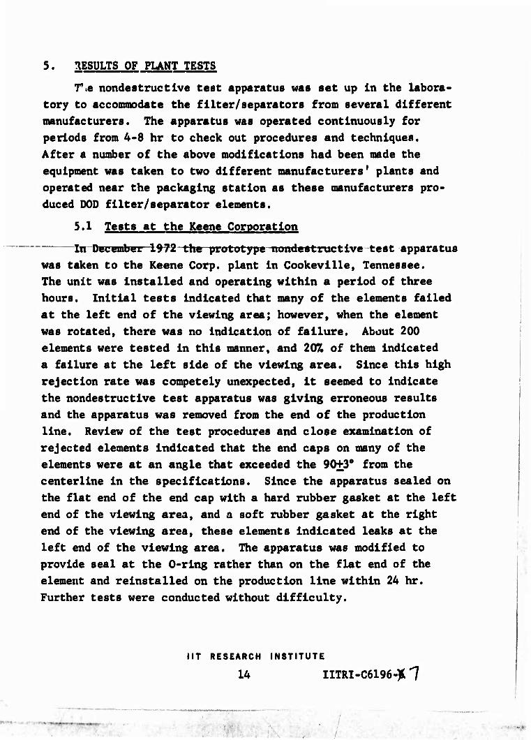
5.1 Tests at the Keene Corporation
fa-December 1972 the prototype nondestructive test apparatus
was taken to the Keene Corp. plant In Cookevllle, Tennessee.
The unit was Installed and operating within a period of three
hours. Initial tests Indicated that many of the elements failed
at the left end of the viewing area; however, when the element
was rotated, there was no Indication of failure. About 200
elements were tested In this manner, and 20% of them Indicated
a failure at the left side of the viewing area. Since this high
rejection rate was competely unexpected. It seemed to Indicate
the nondestructive test apparatus was giving erroneous results
and the apparatus was removed from the end of the production
line. Review of the test procedures and close examination of
rejected elements Indicated that the end caps on many of the
elements were at an angle that exceeded the 90+3° from the
centerllne In the specifications. Since the apparatus sealed on
the flat end of the end cap with a hard rubber gasket at the left
end of the viewing area, and a soft rubber gasket at the right
end of the viewing area, these elements Indicated leaks at the
left end of the viewing area. The apparatus was modified to
provide seal at the 0-rlng rather than on the flat end of the
element and reinstalled on the production line within 24 hr.
Further tests were conducted without difficulty.
NT RESEARCH INSTITUTE
14 IITRI-C6196-)t 1
j ■
/

It should be noted that the test apparatus was located Just
prior to the final inspection and packaging of the DOD element.
During the previous few days, there had been a number of rejects
produced by this line and it had been shut down until the diffi-
culty could be located and corrected. The elements being
Inspected by the nondestructive test were not elements which had
been approved for shipment and during subsequent operations
elements with end caps which were not at 90° to the centerline
of the element were rejected by the final Inspector on the line.
Approximately 3000 standard DOD elements were evaluated with
the nondestructive test equipment at this plant. Two elements
were found to be defective. The defective areas were about £-in.
in diameter and were marked and returned to MERDC for testing.
Poor coalescence was found in both marked areas and further
investigation resulted in the finding that there was poor binding
between the end caps and the element bodies.
As a result of our testing, it was apparent that very few
defective elements would be found during normal production and
the plant personnel were kind enough to suggest various defects
which they could build into the elements for check-out of the
test apparatus. Several defective elements were deliberately
fabricated and tested. The results of these tests are given in
Table 1.
In all cases, it was possible to detect the defect in a
maximum period of 20 sec; most of the defects were detected in
about 2 sec.
5.2 Tests at Banner Engineering Company
In January 1973 the nondestructive test unit was installed
at the end of the DOD element production line at Banner Engineer-
ing Company. During a period of approximately 10 days, 3000
elements were tested and two defective elements were found. These
elements were supplied to MERDC for evaluation and found to fail
the coalescence test.
NT RESEARCH INSTITUTE
15 IITRI-C6196-fc 7
' -' ~--r^n jmm ~~--

Table 1
DETECTION OF DELIBERATELY BUILT-IN ELEMENT DEFECTS (Keene Corporation)
Media defectb Test results
Pleated proper silt, 8 In. Pleated paper silt, 2 to 4-in. cuts Coalescing layer, 3/4-in. hole Coalescing layer, jxj-in. hole Hole drilled in element, 1/8-in. diam. Hole in plug in clement, 0.030-in.
Do tec:able, 10-20 sec Detectable, 10-20 sec Detectable, 2 sec Datee table, 2_«ec Detectable, 2 sec Detectable, 2 sec
End cap defects
bc^-in. hole In paper and coalescing media but covered by tape
50% of end cap not sealed 3/8-in. strip not sealed 3/4-in. strip not sealed 1-in. strip not sealed
Test results
Detectable, <2 sec
Detectable, <2 sec Detectable, 10-20 sec Detectable, <2 sec Detectable, 10-20 sec
NT RESEARCH INSTITUTE
16 IITRI-C6196-'f7
-^

The elements produced by Banner Engineering Company are somewhat different In construction from the elements produced by the Keene Corporation and plant personnel again agreed to deliberately produce a number of defective elements for evalua- tion of the test apparatus. Results of tests of these elements are given In Table 2.
5.3 Acceptance by Plant Personnel
In both cases, plant personnel were very receptive to the concept of nondestructive testing of filter/separator elements as they were produced. All the plant personnel from the line operators to management and laboratory^ataff were highly Inter— es ted In the concept and viewed the nondestructive equipment as a means of further Increasing the quality of their product. Complete cooperation was received during the two test periods and it is apparent that the use of this apparatus will be wel- comed by plant personnel.
NT RESEARCH INSTITUTE
17 HTRI-C6196-1((1
- vm ■ - I

Ü 0 o o 0) (U (1) 0) s S aj a) aJ a) CO (0 (0 CO (0 0) CO CO CO CO
m m w IH r-t cn en in <$ in rH H 1 V V i 1 H 1 1
0) • 1 rH es CO N i CM en 4J 00 00 4J 00 H r-l 3 d (0 CO 0) 0) M V4
0) 0) (U 0) 0) 0) a) u v a) 4J .H H r-l iH f-l rH 4J H iH H iH to J3 ^ ^1 ^3 Xt ,Q CO ja x> Xi xt 0) H 5 3 3 2 2 5 (U
H to td rt cö 4J 4J 4J 4J
o u u o o o a} « al a» CO 0) 0) 0) (U (U a) H 4J 4J W +J ■p 4J 4J 4J 4J -U Ü 0) CD <ü (U (U <u a) a) a) a)
O O O Q Q Q Q Q Q Q
o
s M/^
58 •0
dS 1 $ a
S5 »4 •o to -0 H O (U U 0)
1 O. H M
a •J 0 § a) cd HO 43 U
CM p u 4J a PQ 00
<u 43 • a) a h fH >4^-l •H r-l q A «w w
•H 4J M CO cd w «
M o •o •O 43 a> 1 4J
H §.§ • 6 «^ •> CO •
»1-) 0 0 i—1 c r*» iH 5 • Tl
PQ S1 (0 1-1 I-t -V. •H 0 C I 4J l-t 1 • t^ T) «rl H(W
MM Ü • • o a CO 43 1
äu «4-1 a a + CO o
•H 1 5 oo e ^ 'S
a a) «} 1 1 0) 0) • -tf o "^ »H X> 4J
fa c •d VO VO iH i-l o cn i « « . HKu 43 0) 2 2 >. •d 0<2 a »Q Xi
■M u
^3 <s •O 43 <U 4J 85>*' •0 • t <u •
H £ co « 0 c 4J 4J -H -H s 5 i s §•§
y «fl CO 1 1 •H
Ü
1
S'S ä 4i i OJ o< * A •H M •H H 4J 4J
CM »* «3 43 4-> (0
43 |
u a co ca co d cd <ü 00 r-( H
M M i s g cd H $ « O 4) 4J 4J a o. op op its s
#*
^ 1 (J o •o u •H f« i-t
U U m m g CO h fl) fl) at a) a) a) 0) SS g g 4J 4J .-1 iH H
^ s g g g fall O fa u u ta fe O O <5 Ü
MT RESEARCH INSTITUTE
18 IITRI-C6196-)87
■•
■ ■ ■■■.■■■

6. CONCLUSIONS AND RECOMMENDATIONS
As a result of the work conducted on Phase II of this program It can be concluded that:
• The prototype apparatus which has been developed is satisfactory for the evaluation of the procedures and operation at the end of a production line producing up to 1000 elements per 8-hr shift.
• It may be desirable to redesign the unit for one-man instead of two-man operation inasmuch as the labor cost represents a major fraction of the cost associated with testing.
• The unit succeeded in detecting defects in elements with no visual flaws. These elements failed the coalescence test.
• All the elements which failed the non- destructive test also failed the coalescence test.
As a result of the studies, the following recommendations can be made.
• Further evaluation of the nondestructive test equipment would be desirable to statistically determine rejection rates. A program to test at least 20,000 elements is reconmended.
• A statistically significant number of elements passed by the inspector and by the nondestructive test apparatus should be destructively tested to determine capability of the nondestructive test apparatus.
MT RESEARCH INSTITUTE
19 IITRI-C6196-^ 7
\
■ ■