Embed Size (px)
Citation preview
Non-linear FEM project report
By
CHODVADIYA KEYUR 17310R004\
DHAMODARAN R 173104003
Supervisor
Prof. RAM KUMAR SINGH
DEPARTMENT OF MECHANICAL ENGINEERING
IIT BOMBAY 2019
Table of Contents
List of Figures……………………………………………………………………………………….3
1. Large deformation of a cantilever beam .......................................................................... 4
1.1 Problem description ....................................................................................................... 4
1.2 Form Geometry ............................................................................................................. 4
1.3 Element and Material property ...................................................................................... 4
1.4 Mesh size ................................................................................................................. 4
1.5 Boundary conditions and Loads .................................................................................... 5
1.5 Solution ..................................................................................................................... 5
1.6 Results and discussion .................................................................................................. 6
2. Comparison of LEFM(Linear elastic fracture mechanics) and EPFM ( mode 1) .............. 7
2.1 Problem description ....................................................................................................... 7
2.2 Form Geometry ............................................................................................................. 7
2.3 Element and Material property ...................................................................................... 7
2.4 Mesh size ...................................................................................................................... 8
2.5 Boundary condition and loads ....................................................................................... 9
2.6 Solution ......................................................................................................................... 9
2.7 Results and discussion .............................................................................................. 111
3. References .................................................................................................................. 133

List of Figures
Figure 1 - Schematic model of the cantilever beam ...................................................................... 5
Figure 2 - Finite element model of the cantilever beam in ANSYS .............................................. 5
Figure 3 - Bending moment along the beam H = 50mm and B = 1mm ....................................... 5
Figure 4 - Bending moment considered for various points along the length of the beam ........ 6
Figure 5 - Computational (Ansys) vs Analytical results for bending moment ............................. 6
Figure 6 - Plate with crack of zero degree angle ............................................................................. 7
Figure 7 - Experimental data for plastic deformation on OFHC copper ....................................... 8
Figure 8 - Boundary condition ............................................................................................................ 9
Figure 9 - Equivalent elastic strain for elastic material ................................................................... 9
Figure 10 - Equivalent elastic strain for elastic plastic material .................................................. 10
Figure 11 - Equivalent stress for elastic material .......................................................................... 10
Figure 12 - Equivalent stress for elastic plastic material .............................................................. 11
Figure 13 - Stress strain diagram for elastic plastic material obtained from material
deformation of a point near the vicinity of crack tip ....................................................................... 11

1. Large deformation of a cantilever beam
1.1 Problem description
In this problem we are going to model a large deformation cantilever beam with
several loads acting on it as shown in the schematic diagram, the equations for
bending moment at any point (x,y) is as follows:
= P(a − x) + nP (b − y)+ [u(s − ) − u(s − )]………………………(1)
The analytical solution is calculated at various points along the beam and
plotted against the numerical solution obtained from the Ansys.
Here the cross section of the beam is rectangular with 50 mm height and 5 mm
thickness
1.2 Form Geometry
Total length of the beam = 500 mm
a = 499.78 mm
b = 10.88 mm
= 100 mm
= 300 mm
n = 3
1.3 Element and Material property
Material used for the analysis purpose was structural steel and the
elements used were beam 188.
1.4 Mesh size
The length of each element is 0.2 mm.

1.5 Boundary conditions and Loads
Figure 1 - Schematic model of the cantilever beam
Figure 2 - Finite element model of the cantilever beam in ANSYS
1.5 Solution
Figure 3 - Bending moment along the beam H = 50mm and B = 1mm

Figure 4 - Bending moment considered for various points along the length of the beam
Because of the interpolation even though the beam is one dimensional we will
get stresses in 3D through the thickness and height we have provided.
Analytical results were calculated for the same points shown in the above
figure with the help of eq(1).
Figure 5 - Computational (Ansys) vs Analytical results for bending moment
1.6 Results and discussion
From the above graph it can be clearly seen that the numerical results shows
very good similarities with the analytical results.
One important point to note is that the mesh contains 5001 nodes and 2500
elements and computational values are always found to be higher than that of
-5.00E+04
0.00E+00
5.00E+04
1.00E+05
1.50E+05
2.00E+05
2.50E+05
3.00E+05
0 100 200 300 400 500 600
Ben
din
g m
om
ent
(N-m
m)
Distance from fixed end
Computational (Ansys) vs Analytical results
for bending moment
Computational (Ansys)
Analytical

the analytical values by a small margin, the reason for this is supposed to be
the stiffness of the finite element model.
2. Comparison of LEFM (Linear elastic fracture mechanics) and
EPFM ( mode 1)
2.1 Problem description
In this problem comparison of LEFM with EPFM will be carried out for
2D case where a plate with length 50 mm and height 30 mm is fixed at
bottom and at the centre of the plate there is a crack of 15 mm length at
zero angle.
The first problem was solved for LEFM considering material to be linear
and no plasticity data was provided while in the second problem
experimental data was feed to the material of the problem.
2.2 Form Geometry
Figure 6 - Plate with crack of zero degree angle
2.3 Element and Material property
For this analysis 2D plane stress linear elements are used ( as linear
elements are only supported for fracture analysis). OFHC copper is used
as the material as its experimental data was available.

Figure 7 - Experimental data for plastic deformation on OFHC copper
2.4 Mesh size
Body size mesh = 1.5 mm
Sphere of influence near crack tip = 10 mm diameter and centre at crack tip
Size of mesh in the sphere of influence = 0.2 mm

2.5 Boundary condition and loads
The boundary condition for the following problem is shown as follows:
Figure 8 - Boundary condition
Lower part of 15 mm is fixed and upper part is given a displacement of 0.5 mm
2.6 Solution
Figure 9 - Equivalent elastic strain for elastic material

Figure 10 - Equivalent elastic strain for elastic plastic material
Figure 11 - Equivalent stress for elastic material

Figure 12 - Equivalent stress for elastic plastic material
Figure 13 - Stress strain diagram for elastic plastic material obtained from material deformation of a point near the vicinity of crack tip
2.7 Results and discussion
The stress-strain diagram plotted from the plastically deformed plate of a node
near the vicinity of the crack tip shows that the material has deformed
according to the plasticity data provided.
The maximum stress intensity factor for LEFM in mode I is 4047 Mpa√
while that for EPFM it is 2513 Mpa√ while critical stress intensity factor for
mode I is 2700 Mpa√ . These values suggests that if we would have
considered LEFM then our crack would have definitely propagated while for
EPFM the stresses at the crack singularity has been released because of the
plastic deformation and thus it shows very small equivalent stress and strains
and it suggests that the crack will not propagate as the stress intensity value
is smaller than the critical value.
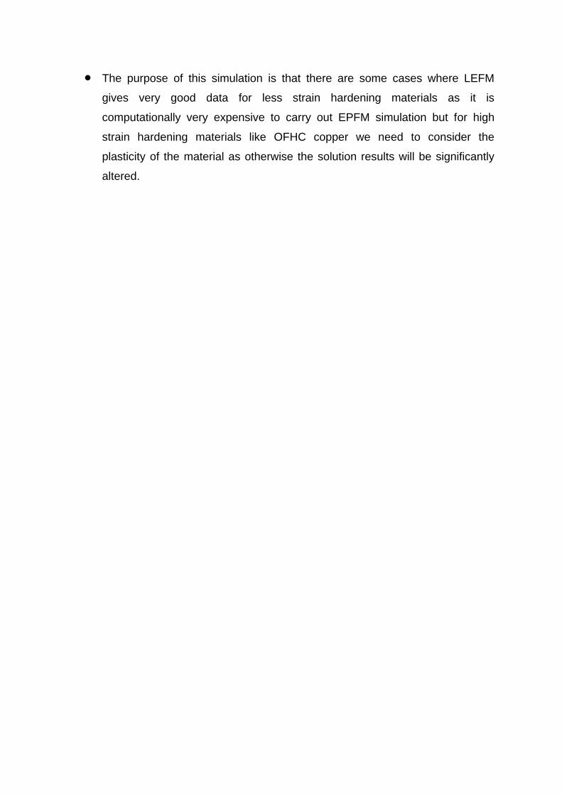
The purpose of this simulation is that there are some cases where LEFM
gives very good data for less strain hardening materials as it is
computationally very expensive to carry out EPFM simulation but for high
strain hardening materials like OFHC copper we need to consider the
plasticity of the material as otherwise the solution results will be significantly
altered.

3 References
1) A. Banerjee, et al., Large deflection of cantilever beams with geometric non-
linearity: Analytical and numerical approaches.


![High-Order Adaptive Extended Stencil FEM with Linear ... · arXiv:1603.09325v4 [math.NA] 9 May 2016 High-Order Adaptive Extended Stencil FEM with Linear Elements∗ Rebecca Conley†](https://img.dokumen.tips/doc/110x75/5f09c4c17e708231d4286a2e/high-order-adaptive-extended-stencil-fem-with-linear-arxiv160309325v4-mathna.jpg)