Embed Size (px)
Citation preview

1
NON-LINE-OF-SIGHT (NLOS) COMMUNICATIONS – COFDM FIELD TESTING RESULTS
Arthur E. Michaud,* Mark Donaldson†
The role of unmanned ground vehicles (UGV) is expanding from counter im-provised explosive device (C-IED) to reconnaissance missions. This along with first responder scenarios are challenging traditional communication systems presently operating with line-of-sight (LOS) navigation objectives. Unmanned systems including, ground and aerial, are evolving to meet new capabilities such as those associated with situational awareness and confined space operation. This expanded role is requiring NLOS operation whether over a hill, behind vegetation, underground, or in urban settings. The Coded Orthogonal Fre-quency Division Multiplexing (COFDM) digital modulation technique has been touted for its NLOS capabilities. This paper reviews the technical benefits re-garding NLOS and provides observation and test results of several recent field experiments. The results include a comparison of radio payloads involving Wi-Fi 802.11G OFDM, COFDM point-to-point RF video and IP data transmissions, along with various RF power output levels and frequency bands.
INTRODUCTION
The mainstream use case for production level unmanned ground vehicles (UGV) was and con-tinues to be as counter improvised explosive device (C-IED) for deployed DoD and Civilian ro-bots. The C-IED mission requires constant eyes on the UGV while a tele-operator controls the robot. Derived UGV communication payload requirements for this use case are relatively simple with line-of-sight distances in the 300 meter range. The current mission ranges have increased up to 800 meters or so, to provide additional protection to the IEOD team.
Unmanned systems including, ground and aerial, are evolving to meet new capabilities such as those associated with situational awareness and confined space operation. This expanded role is requiring non-line-of-sight (NLOS) operation whether over a hill, behind vegetation, under-ground, or in urban settings. Civil unmanned systems and especially the new generation of un-manned aerial vehicles (UAV) for urban applications are challenged beyond the simple LOS communication payload capabilities. NLOS situations raise havoc with RF microwave transmis-sions due to either absorption and/or multipath reflections. Even when it appears to be a LOS
* Director Product Management, Sales/Marketing, Cobham Surveillance, DTC Products, 486 Amherst Street, Nashua, NH, 03063, USA. TEL 800.233.8639, www.cobham.com/dtc † Senior Systems Engineer, Sales/Marketing, Cobham Surveillance, DTC Products, 486 Amherst Street, Nashua, NH, 03063, USA.

2
wireless situation, multipath interference is generated by various reflective objects such as build-ings, moving vehicles, and both positive (hills) and negative (culverts/gullies) terrain deviations. A transmission, which provides multipath immunity and works well in non-line-of-sight situa-tions, is Coded Orthogonal Frequency Division Multiplex (COFDM).1
Radio communication payloads are being challenged by the end users to support these new NLOS use cases. Cobham Communications has been actively involved in the last 12 months field testing and evaluating both LOS and NLOS scenarios. The results of this extensive testing are summarized in this paper.
BACKGROUND: WHAT IS COFDM?
COFDM (Coded Orthogonal Frequency Division Multiplexing) employs a technology that was introduced for the television terrestrial broadcasting and ENG markets. In terrestrial broad-casting of HDTV (High Definition Television), it is known as the DVB-T standard (Digital Video Broadcast Terrestrial). This standard employs up to 4,000 carriers spread over 6 to 8 MHz of bandwidth.3
COFDM has been touted as exhibiting advantages within challenging RF environments such as urban settings, within buildings, uneven terrain, and underground (garages, tunnels, caves, and culverts).
Exceptional Spectrum Efficiencies
A narrowband capability is available as a non-standard configuration which enhances the range penetration by increasing receiver sensitivity and significantly improves operation within congested frequency band environments. See Figure 1. Six (6) 2.5MHz communication links utilizing 400 sub-carriers occupy the same bandwidth as one (1) 17MHz traditional analog FM channel, thus you can expect to operate more unmanned systems with less interference within the radio spectrum available for your mission.
Figure 1. Narrowband Efficiency

3
Multipath Resistance/NLOS Operation
Conventional wireless data transmission is done by modulating a single microwave carrier with a high data rate stream. COFDM is a way of wirelessly sending data by dividing the high data rate stream up into many lower data rate streams and modulating many carriers (sub-carriers) with these low data rate streams. The sub-carriers are all closely spaced to each other in an or-thogonal (90 degree) relationship so there is no cross-talk interference between adjacent sub-carriers. See Figure 2.
Figure 2. COFDM Carriers
By utilizing this technique of putting small amounts of data on many closely-spaced sub-carriers versus putting a large amount of data on a signal carrier, multipath effects are virtually eliminated. This is because a low-data-rate carrier is much more tolerant of signals that are de-layed (due to reflections) than a high-data-rate-carrier would be. In fact, COFDM actually takes advantage of signals that arrive by non-direct paths. Because of this, they can work well in non-line-of-sight high multi-path environments such as urban locations.
Multipath effects occur when the reflected path signal, arriving delayed in time, is superim-posed upon the direct path signal, this causes false data to be detected by the receiver. See Figures 3 and 4.
4
Figure 3. Multipath Reflections
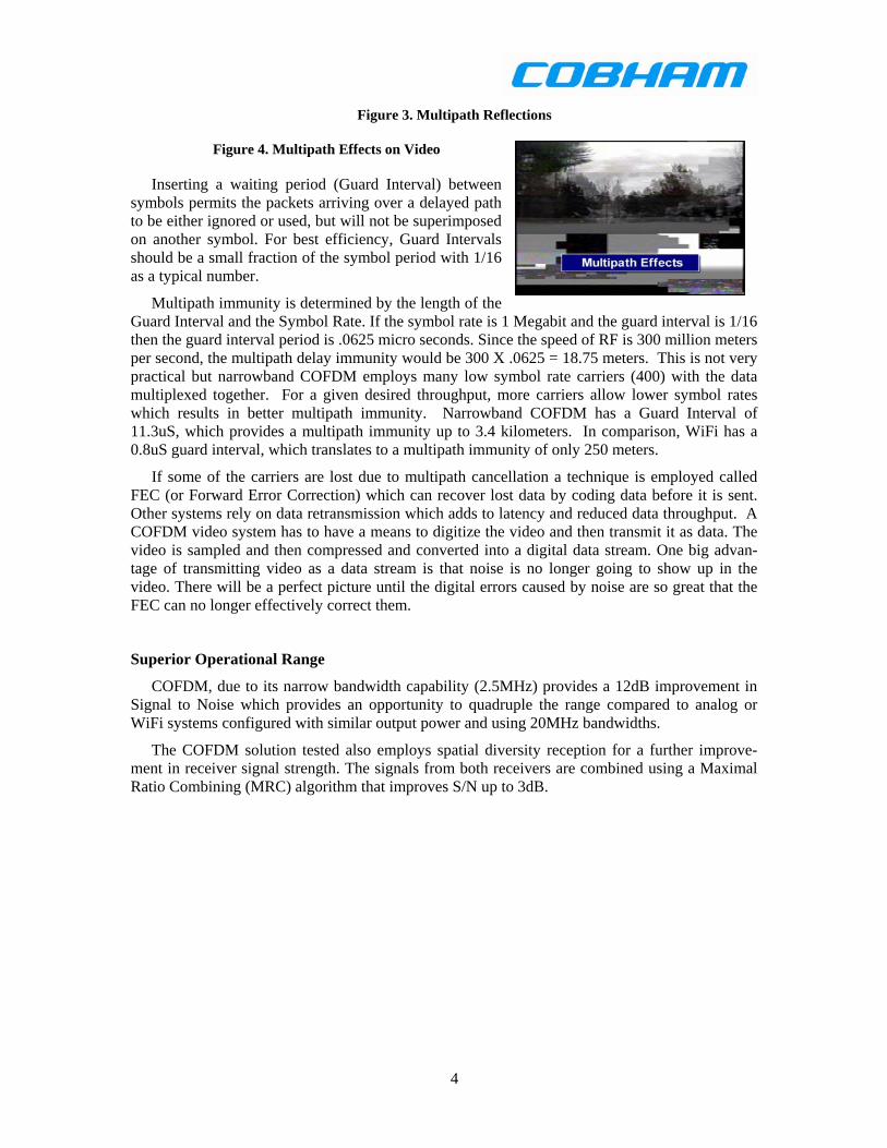
Figure 4. Multipath Effects on Video
Inserting a waiting period (Guard Interval) between symbols permits the packets arriving over a delayed path to be either ignored or used, but will not be superimposed on another symbol. For best efficiency, Guard Intervals should be a small fraction of the symbol period with 1/16 as a typical number.
Multipath immunity is determined by the length of the Guard Interval and the Symbol Rate. If the symbol rate is 1 Megabit and the guard interval is 1/16 then the guard interval period is .0625 micro seconds. Since the speed of RF is 300 million meters per second, the multipath delay immunity would be 300 X .0625 = 18.75 meters. This is not very practical but narrowband COFDM employs many low symbol rate carriers (400) with the data multiplexed together. For a given desired throughput, more carriers allow lower symbol rates which results in better multipath immunity. Narrowband COFDM has a Guard Interval of 11.3uS, which provides a multipath immunity up to 3.4 kilometers. In comparison, WiFi has a 0.8uS guard interval, which translates to a multipath immunity of only 250 meters.
If some of the carriers are lost due to multipath cancellation a technique is employed called FEC (or Forward Error Correction) which can recover lost data by coding data before it is sent. Other systems rely on data retransmission which adds to latency and reduced data throughput. A COFDM video system has to have a means to digitize the video and then transmit it as data. The video is sampled and then compressed and converted into a digital data stream. One big advan-tage of transmitting video as a data stream is that noise is no longer going to show up in the video. There will be a perfect picture until the digital errors caused by noise are so great that the FEC can no longer effectively correct them.
Superior Operational Range
COFDM, due to its narrow bandwidth capability (2.5MHz) provides a 12dB improvement in Signal to Noise which provides an opportunity to quadruple the range compared to analog or WiFi systems configured with similar output power and using 20MHz bandwidths.
The COFDM solution tested also employs spatial diversity reception for a further improve-ment in receiver signal strength. The signals from both receivers are combined using a Maximal Ratio Combining (MRC) algorithm that improves S/N up to 3dB.
5
FIELD DEMONSTRATION OBSERVATIONS AND TESTING
End users moving towards the new NLOS use cases have been looking for realistic validation of the described COFDM theoretical benefits. The following sections are a sample of our obser-vation and testing performed with a combination of end users and independent agencies that have similar interests. *
NY National Guard – Fort Hamilton, NY
NY National Guard Domestic Operations Conference held at Fort Hamilton New York 25-27 August 2008. We had an opportunity to run a few exercises and demonstrate a narrowband COFDM communications solution around and within a very “RF challenged’ environment. The thick granite and mortar walled fort provided a set of ideal test scenarios. A complete video and command control COFDM link was installed on a UGV platform partner’s robot and with the help and observation of the National Guard representatives, the robot operated through the com-plex. The comm. payload was a C-band 250mW IP over COFDM link.
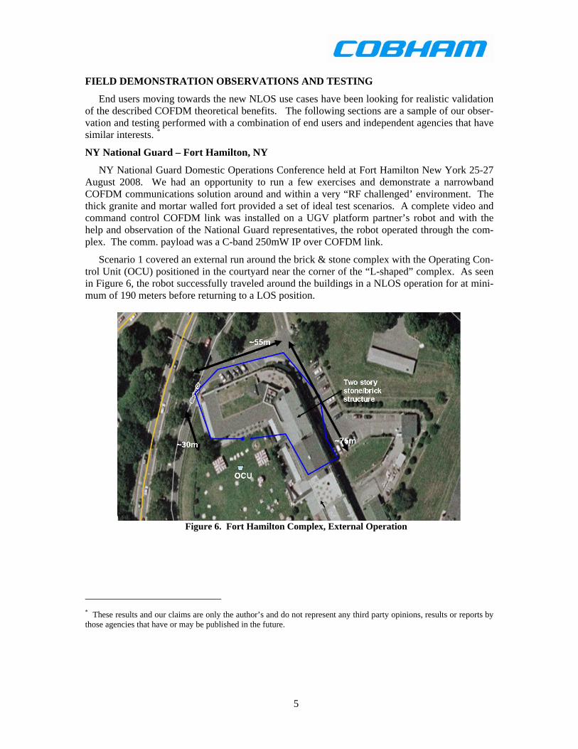
Scenario 1 covered an external run around the brick & stone complex with the Operating Con-trol Unit (OCU) positioned in the courtyard near the corner of the “L-shaped” complex. As seen in Figure 6, the robot successfully traveled around the buildings in a NLOS operation for at mini-mum of 190 meters before returning to a LOS position.
Figure 6. Fort Hamilton Complex, External Operation
* These results and our claims are only the author’s and do not represent any third party opinions, results or reports by those agencies that have or may be published in the future.

6
Scenario 2 included an underground tunnel composed of brick & stone. The OCU remained in the courtyard while the robot was positioned at the far end of the tunnel and operated towards the OCU. Figure 7 displays the location and view within the approximately 30 meter tunnel.
Figure 7. Underground Tunnel
Scenario 3 attempted to enter and transverse the interior of one of the buildings. Again, the OCU was located outside in the courtyard. The robot successfully traveled around the corner and then well into an interior corridor taking several turns up to a distance of approximately 100 me-ters as depicted in Figure 8.
Figure 8. Interior Scenario

7
,
NIST US&R Response Robot Exercise – Disaster City, College Station TX
The Department of Homeland Security (DHS) Science and Technology (S&T) Directorate ini-tiated an effort in 2004, with the National Institute of Standards and Technology (NIST). The intent is to develop comprehensive standards related to the development, testing, and certification of effective technologies for Urban Search and Rescue (US&R) robotics.*, 4 NIST is also col-laborating with the ASTM Task group on robots (E54.08.01) in which the authors are also par-ticipants.† 6
The Robotic Evaluation Exercise held at Disaster City, in November of 2008 was a sponsored NIST event managed by the Texas Engineering Extension Service (TEEX). This event provided the authors with an opportunity for both radio testing and observation of various robotic platforms operating a variety of communication payloads.
This five day event was part of an ongoing NIST program which is now in the phase that characterizes the first responder requirements so that a standard set of tests can be developed and applied to future UMS purchases.
Major emphasis for the authors was LOS/NLOS communications link testing at Riverside air-field.
ID Type PWR
(mW)
Band TX/RX Ant Gain
(dBi)
TX/RX Ant Height
(m)
A COFDM IP 100 C Omni 2dBi/Directional .5m / 2m tripod
B COFDM 250 S Omni 2dBi/ Omni 2dBi .5 / 1
C Analog FM 5000 S Omni 2dBi/ Omni 2dBi .5 / 1
D COFDM 100 C Omni 2dBi/ Omni 2dBi .5 / 1
E WiFi C Omni 2dBi/Directional .5 / 2 tripod
F Spread Spectrum 250 1.9GHz Omni 2dBi/Directional 1 / 2
G Unknown 1000 S Omni 2dBi/Directional 1 / 2
* http://www.isd.mel.nist.gov/US&R_Robot_Standards/ † http://www.astm.org/COMMIT/COMMITTEE/E54.htm

8
LOS: NIST setup a 1 km test field contained “figure 8” test tracks 2m wide with four eye charts. These were placed at 100 meter intervals. The idea was to test not only the range but stress the robot with fine command and control and rotation such that any weaknesses in antenna position would be exposed. The runway distance extended out for another ~500 meters but was not expected to be part of the formal test since light poles and other objects started to intrude in between the robot and OCU station. Receiver antennas max height of 2m, no restriction on power outputs but each radio was characterized for each link, control and video.
Observations: A robot carrying a COFDM IP radio (A) @ 100mW exceeded the LOS track and continued to 1500 meters, well past the 1km goal.
The 250mW S-band link (B) went the full length of the runway 1500m without losing video, this link also used low gain omni directional antennas on both ends of the link.
The 100mW C-band COFDM video link (D), deemed as the worse case due to the high fre-quency band made it to the 950m mark using low gain omni directional antennas on both ends of the link. This was considered very successful for only a 100mW TX and omni directional anten-nas.
SPAWAR attended and brought in a couple of robots and three radios that were interchanged for each test; COFDM IP radio (A) (100mW), WiFi (E) (power unknown), Spread Spectrum (F). All used directional antennas at the OCU. We noted that the UHF WiFi (E) experienced severe UHF interference but made it 600 meters. Spread spectrum (F) was able to go about 500m operat-ing at 1500MHz and using a 250mW output power.
A small robot platform operated with an ’unknown’ radio (G) powered at 1W in S-band traveled out to 370M. The OCU contained directional antennas in a back-pack positioned at table height. See Figure 9 for a graphical result view.
Figure 9. LOS Disaster City
Observations
Conclusion:
The narrow bandwidth of the COFDM links clearly allow superior Line-of-Site range.
9
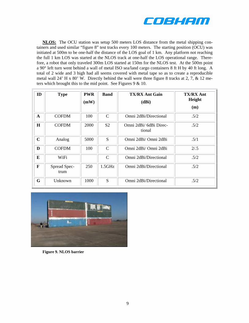
NLOS: The OCU station was setup 500 meters LOS distance from the metal shipping con-tainers and used similar “figure 8” test tracks every 100 meters. The starting position (OCU) was initiated at 500m to be one-half the distance of the LOS goal of 1 km. Any platform not reaching the full 1 km LOS was started at the NLOS track at one-half the LOS operational range. There-fore, a robot that only traveled 300m LOS started at 150m for the NLOS test. At the 500m point a 90° left turn went behind a wall of metal ISO sea/land cargo containers 8 ft H by 40 ft long. A total of 2 wide and 3 high had all seems covered with metal tape so as to create a reproducible metal wall 24’ H x 80’ W. Directly behind the wall were three figure 8 tracks at 2, 7, & 12 me-ters which brought this to the mid point. See Figures 9 & 10.
ID Type PWR
(mW)
Band TX/RX Ant Gain
(dBi)
TX/RX Ant Height
(m)
A COFDM 100 C Omni 2dBi/Directional .5/2
H COFDM 2000 S2 Omni 2dBi/ 6dBi Direc-tional
.5/2
C Analog 5000 S Omni 2dBi/ Omni 2dBi .5/1
D COFDM 100 C Omni 2dBi/ Omni 2dBi 2/.5
E WiFi C Omni 2dBi/Directional .5/2
F Spread Spec-trum
250 1.5GHz Omni 2dBi/Directional .5/2
G Unknown 1000 S Omni 2dBi/Directional .5/2
Figure 9. NLOS barrier

10
Figure 10. “figure 8” operability test section
A robot with a 2W COFDM S-band and 10W Command & Control link (H) was the first robot to peg the NLOS test by completing the test tracks to the middle of the back of the wall, traveling completely behind the containers and then proceeded to extend the test by entering the last container and traveled inside the container to the end and still remain in contact with the OCU. The COFDM signal made its way out the open end of the container back to the OCU 500 meters away positioned at a 90° angle to the opening. The OCU incorporated directional antennas (approximated to provide 6dBi gain.
The robot carrying the COFDM IP radio (A) @ 100mW C band exceeded the NLOS track by completing the full turn and entered into the open container.
Figure 11. NLOS Disaster City Observations
Our hand carried links were not quite as successful on the NLOS course which was attributed to the lower gain Omni Directional antennas on both ends of the link. A C-band 100mW radio (D) went 500m and then was able to go about 3m behind the containers before signal was lost.
The 5W S-band link (C) did successfully go 500m and then work all the way behind the containers for the full length of the barrier.
The WiFi unit (E) started out at 200m from the turn, and still was not able to travel more than 3 m behind the walled barrier.
A small robot platform operated with an ’unknown’ radio (G) powered at 1W in S-band started at approximately ½ of LOS distance (150m from the wall). This unit operated up to the 3m mark behind the wall.
SPAWAR changed out the radio to a Spread Spectrum version running in C-band (F). This unit started at 350m since it only made 700 meters on the LOS testing that occurred on the first two days. Video started to break up at 3m behind wall and completely stopped at 6 meters.
Conclusion: The ability of COFDM to utilize reflections to allow reliable communications in a non-line-of-site scenario was clearly demonstrated in this test.

11
RSJPO – Battle Labs, Fort Benning GA
Sponsored by the Robotic Systems-Joint Project Office (RSJPO) the U.S. Army Infantry Cen-ter and School’s Maneuver Battle Lab (MBL) at Fort Benning, Georgia conducted a comparative performance assessment of a WiFi based radio with a narrow band COFDM IP radio in January 2009.7, 8
COFDM IP radio: 250mW C-band, Omni TX antennas, 9dBi OCU antennas on a tripod
WiFi radio: 400mW C-band, Omni TX antenna, 23dBi OCU antenna on a tripod
The test plan 7 called out eight (8) test scenarios:
• Flat, open terrain, including land & water (LOS)
• Simulated urban streets, inside buildings, and building to building (NLOS)
• Realistic urban terrain using downtown Columbus, GA (LOS & NLOS)
• Simulated subterranean terrain with an above ground tunnel complex (NLOS)
• Negative elevation use case ( LOS & NLOS)
• Variable rolling terrain (LOS & NLOS)
• Wooded trails (LOS & NLOS)
• Indoor terrain (NLOS)
LOS:
In regards to LOS / rolling scenarios, COFDM out performed WiFi by almost a 3-1 ratio in distance. COFDM excelled in the variable rolling terrain scenario that exceeded a 6-1 factor with a total distance permitted of 3 km. The COFDM radio ran out of the accessible range during this test and thus was limited to the 3 km. See Table 1 for results summary
Scenario WiFi Distance (meters) COFDM Distance (meters)
McKenna Landing Strip 572 1042 (max possible distance)
Downtown Columbus 330 700
Woodland trail (test 12) 208 337
Woodland trail (test 13) 293 455
Cyclone Road (Negative Ele-vation)
320 995
Carmouche Range (Variable Rolling Terrain)
511 3000
Table 1. LOS Results summary

12
NLOS:
Simulated Urban Streets: The McKenna Village MOUT site was used in this test scenario. See Figure 12.
The COFDM equipped robot circled the entire complex twice, and navigated all roads and in between buildings without loss of the communications link. This unit then ran from the start point, to the far end of the village, out the back perimeter of the village along a dirt trail to the McKenna Field Landing Strip which is approximately 650 feet from the village.
The WiFi robot was limited in operation along the first street (left or right, but could not oper-ate around the next set of buildings and thus the next crossing street.
Figure 12. McKenna Village
Simulated Inside Buildings: The three story building in the McKenna village was used with various OCU positions that ranged from at the entrance door to across the street (building-to-building).
Figure 13 represents the areas covered by COFDM and WiFi radios respectively.
The COFDM radio, maintained communications up to the last room of the third floor, whereas the WiFi unit could not cover the back of the second floor and was not able to reach up to the third floor.

13
Figure 13. NLOS Inside Building
Realistic urban – Downtown Columbus:
The COFDM radio followed a route passing parallel to a large building (shown in Figure 14), executed a 90 degree turn to the north, directly behind the building.
The Wi-Fi equipped robot made a distance of ~100 yards past the 90 degree turn, behind the building. The COFDM equipped robot continued on and made it 325 yards behind the building.
Figure 14. NLOS Downtown Columbus
COFDM RADIO
WiFi Radio

14
Simulated subterranean terrain: OCU positioned at the entrance to the corrugated steel tun-nel resulted with both radios successfully circumnavigating the steel portion of 168 linear feet.
OCU at Entrance Concrete Tunnel resulted in the WiFi platform only averaging 75 linear feet through this complex and each time could not navigate past the far right side corner. The COFDM equipped robot circumnavigated the entire concrete tunnel on all attempts.
The OCU was then moved away from the tunnel entrances. The Wi-Fi equipped robot lost communications after travelling about 170 feet, in the first concrete tunnel corner. The COFDM unit travelled about 240 feet, to the second concrete tunnel corner.
The OCU was moved 150 feet away on top of a 15-foot berm. The Wi-Fi unit lost communi-cations about 169 feet into the tunnels. The COFDM unit progressed the entire route through both tunnels with no adjustment or panning of the antenna.
The Wi-Fi equipped platform was tested again, with panning of the antenna and successfully circumnavigated the tunnels.
The OCU was then moved to an acute right angle 200 feet away. Again, the WiFi unit lost communications in the same corner at 160 feet. The antenna was panned in an attempt to regain communications with no success. The COFDM equipped platform circumnavigated both tunnels with no issues. See Figure 15.
Concrete & Steel Tunnel Non-Line of Sight:
COFDM RADIO
WiFi Radio
Figure 15. Simulated Tunnels

15
Indoor multi-level environment was accomplished with the use of the Infantry building:
Test 1: The robots travelled 440 feet down a hallway before making a 90-degree left dogleg turn. The COFDM radio yielded a 38% improvement over the WiFi radio - travelling 713 feet as compared to 560 feet.
Test 2: Negotiating a live elevator shaft with the OCU on the ground floor.
The WiFi unit lost communications on the elevator at the Third floor. Communications were restored when the doors opened. Traveled 64 feet west then 42 feet east. Did not communicate at the fourth floor.
The COFDM robot navigated the entire second floor, including closed-door latrines and an auditorium.
Third floor: 292 feet west (as far as it could go) and 154 feet east.
Fourth floor: 117 feet west and 94 feet east.
Fifth floor: 65 feet west then 56 feet east.
Sixth floor: 50 feet west then 46 feet east.
Communications was never lost in the elevator with doors closed. The test for the COFDM equipped robot was limited by lack of floors above the sixth floor. See Figure 16.
Figure 16. Indoor Multi-floor Test

16
Fort Hood TX
Cobham Surveillance had the opportunity to test Digital COFDM RF solutions at Ft. Hood, Killeen, Texas along with a major integrator and the Army Engineer Corp.; Counter Explosives Hazard Center over a three day period in July 2009. A combination of Stressing out the commu-nications capabilities in both LOS and NLOS scenarios were extremely successful as discussed below.
Radio equipment tested: COFDM 250mW Transmitter w/omni antenna, Diversity Receiver w/ 9dBi directional antennas, S-band frequency.
LOS: Fort Hood was the first opportunity with access to a LOS ground site that provided a LOS range in excess of 3 km. In fact it required that the OCU and transmitter be located at two hills: Anderson Mountain & Castle Mountain which are at opposites ends of the fort. The COFDM 250mW radio successfully communicated at a range of 17 km. Signal to noise was still excellent at 11dB indicating much greater range being possible, 35km or more. A preliminary test using the DMPRC Range Operations at Clabber Creek achieved a 3 km + result using a 100mW C band radio with omni antennas. Signal was lost due to range road coming to an end at 3km.
NLOS: A simulated urban environment named the Hargrove MOUT site is shown in Figure 17. Four tests were performed with the OCU positioned at the same location.
Test 1: Utilizing a 250mW S band TX with omni antenna and 9dBi directional antennas on the RX. Successfully maintained communications down the road ~ 70m and then down and into a culvert under the road (@ 90° angle) which was 30 feet in length.
Tests 2/3: Utilizing a 250mW S band TX and omni antenna on the TX and 9dBi directional antennas on the RX. Traveled through a couple of buildings while maintaining communications. Here, we confirmed with the Combat Engineering team that our set back was far enough back (70 meters) and we navigated the culvert with seamless video. The radio also navigated a building from a set back of 70 meters. Having a setback has become an important requirement for the new missions.
Test 4: Utilizing a 250mW S band TX and omni antennas on the TX and the RX. Negotiated travel around the complete perimeter of the MOUT.
Figure 17. Fort Hood
MOUT Site

17
Subterranean: Fort Hood has an impressive hardened tunnel complex originally built post WW2 for the storage and maintenance of nuclear warhead missiles. It contains long corridors, rooms and chambers that provided the most complex of subterranean stress testing. Figure 18 displays the course and results.
Radio Equipment: Same as the LOS test gear, plus an additional 1W radio was also tested.
Two tests involved traveling down a corridor for a distance of 795 feet, then turning left and right (90°) turns, followed by two additional 30° turns. Communications were successful up to and through the third turn at distances of up to 515 feet from the first turn. The 1W tested in similar range to the 250mW which indicates that the multipath environment was the key factor in this range test. WiFi radios have been tested in this tunnel complex in the past and have needed a number of repeaters (bread crumbs) to provide reliable communications.
Figure 18. Fort Hood Tunnel Complex
18
CONCLUSION
• The LOS capabilities of COFDM in comparison to WiFi and Spread Spectrum may be viewed as significant; however with the new mission requirements of NLOS, a greater dis-tance in itself is not the relevant measurement. NLOS creates a Pass/Fail measurement which results in either being able to accomplish the mission at hand or increasing the risk of safely completing the mission. Clearing a room on a third floor inside a building demands a com-munications link that is capable of reaching into that area. COFDM has clearly demonstrated that capability compared to sever limitations of WiFi and Spread Spectrum technologies.
• Validated an important user requirement that the OCU would be at a set back where the op-erator would be in a safe position. This applied to in-building and subterranean environ-ments.
• The multipath immunity up to 3.4 Kilometers for narrowband COFDM was validated with the many LOS tests, especially in an urban environment that presents a significant multipath challenge.
• Subterranean testing confirmed the significance of multipath issues and demands technology that is multipath resistant.
• In many cases, COFDM outperformed the competition that had higher RF output power and higher gain antennas.
• COFDM performance was similar in both Point-to-Point digital video and two-way IP radio configurations.
• McKenna Village & Hargrove MOUT – Simulated streets: COFDM circumnavigated both villages and navigated between buildings.
• Inside buildings: COFDM navigated all floors (3) and stairwells of the three story McKenna building vs. 1 ½ floors for WiFi. Infantry building presented a significant challenge to WiFi which only communicated up to the third floor vs. COFDM that traveled up through all six floors, even when the OCU was at the bottom floor outside of the elevators with elevator doors closed.
• Downtown Columbus: COFDM executed a 90˚ turn and traveled an additional 350 yards over WiFi. Even with a LOS, the multipath resistance proved to benefit the 250mW COFDM radio over the 1W WiFi with a 2-1 ratio.
• Simulated and actual Tunnels: COFDM doubled the performance of the WiFi radio.

19
APPENDIX A: GLOSSARY
C-IED – Counter Improvised Explosive Device
COFDM – Coded Orthogonal Frequency Division Multiplex A form of spread spec-trum that has particularly effective multipath interference rejection properties.
DVB-T – Digital Video Broadcasting - Terrestrial; A European-based consortium standard for the broadcast transmission of digital terrestrial television involves COFDM modulation.
IP – Internet Protocol is a protocol used for communicating data across packet net-works
Kb/s or kbps – Kilobits per second – one thousand data bits, zeroes and ones, per second. This is a measure of data rate.
Latency – The delay usually caused by processing and transmission and reception and display of the video or sensor data from the UAV. Also important on the control link. A UAV/UGV data-link with high la-tency makes the vehicle hard to control.
Link Margin – The amount in dB above that required to overcome path loss for minimum safe control of the UAV.
LOS Line-of-sight – straight line path with no obstructions between transmitter and receiver antennas sometimes called DLOS or Direct Line of Sight.
MOUT – Military Operations on Urban-ized Terrain training facilities that simulate urban and village environments.
NLOS – Non-Line-Of-Sight – An ob-structed RF path that may include hard ob-ject or soft such as foliage
OCU – Operator Control Unit. This man-portable packaging of the basic ground station is the current trend.
Payload – The design maximum weight that a UAV/UGV can carry beyond that re-
quired for basic operations and fuel ex-pressed in ounces or kg. Examples: IR Cam-era, Laser, Ordnance, EW, DF, radio hard-ware.
Platform – The name of the UAV/UGV.
RF Radio frequency – Also used gener-ally to refer to the radio waves themselves.
Range – The maximum distance in a straight line that the platform can cover usu-ally expressed in Miles or km.
RAV – Remote Autonomous Vehicle – An unmanned vehicle capable of executing a preset mission plan with no guidance from a human pilot, other than initial takeoff and landing.
RPV – Remote Piloted Vehicle – An unmanned vehicle capable of being con-trolled from a distant point through a com-munications link sometimes called a data link. It is normally designed to be recover-able.
Mb/S – or Mbps Megabits per second
UAV – Unmanned (or Uninhabited) Ae-rial Vehicle - A powered, aerial vehicle that does not carry a human pilot.
UGV – Unmanned Ground Vehicle – A powered ground vehicle that does not carry a human driver. An unmanned ground vehi-cle may be remotely driven (RPV) or it may be autonomous (RAV).
Video Link – This data stream is nor-mally wide (high data rate) and includes real-time video from one or more cameras, sensor data and possibly, audio information.
802.11 – A CDMA (code division multi-ple access), TDMA (Time Division Multiple Access) or OFDM (orthogonal frequency division multiplex) spread spectrum wireless network standard.

20
REFERENCE 1 Michael J. Murphy and Mark Donaldson, " DIGITAL MICROWAVE LINK for UNMANNED VEHICLES”, DTC Communications, Inc. 2005. 2 Mark Donaldson, " Reliable Wireless Video for First Responders ”, DTC Communications, Inc. 2008. 3 DVB-T standard ETSI EN 300 744 V1.5.1 (2004-06) 4 National Institute of Standards and Technology (NIST) Department of Homeland Security Urban Search and Rescue Robot Performance Standards 5 “New Communications Tools Help Emergency Responders”, CNN (10/29/08) Walton, Marsha 6 ASTM International Committee on Homeland Security Applications; Operational Equipment; Robots E54.08.01 7 Comparative study of COFDM and WiFi radios on a robotic platform for Robotic Systems-Joint Project Of-fice,Warren, MI, main contacts: Mike Kennedy, Experimentation Manager, Robert Jones, Experiment Officer, U.S. Army Maneuver Center, Maneuver Battle Lab, Ft. Benning, GA. TEST PLAN AND REPORT DISTRIBUTION AUTHORIZED TO U.S. GOVERNMENT AGENCIES DEC 08. OTHER REQUESTS FOR THIS DOCUMENT MUST BE REFERRED TO COMMANDER, U.S. ARMY INFANTRY CENTER, ATTN: ATZB-IS, FORT BENNING, GEORGIA 31905-5273 8 Lily Gordon, Benning tests robots on downtown streets, Unmanned ground vehicles to roam front street, Ledger-enquire, January 14, 2009-