Embed Size (px)
Citation preview
POSEIDON Clamp-On Ultrasonic Flow and Energy Meter
Non-Invasive Flow and Energy Measurement

2
Non-Contact MeasurementBuilt for non-intrusive fow and energy measurement, the Kompauto Poseidon by Badger Meter provides accurate and repeatable flow measurement for full pipe applications ½ inch or larger. The Poseidon is ideal for applications such as cooling lines, raw sewage flows, water distribution, and processes where system shutdown is impossible. Without shutting down a process or breaking into piping, the Poseidon clamps onto the outside of the pipe and does not contact the liquid being measured; therefore, it can be installed and fully operational in minutes. The clamp-on design offers low cost installation and eliminates worries of fluid compatibility and pressure head loss. With no moving parts, there is no mechanical wear, so repair kits or replacement parts are not needed.
With accuracy at ±1 percent and repeatability at ±0.5 percent of reading and a large bi-directional measuring range, the Poseidon ensures reliable readings at low and high flow rates. The meter features a rugged, compact aluminum enclosure, easy-to-read digital display, optional keypad, and a totalizer featuring forward, reverse and net total. Data is relayed through a USB port and connectivity options include Modbus RTU, BACnet MSTP, BACnet/IP, EtherNet/IP, and Modbus TCP/IP. Users can easily configure, calibrate and troubleshoot meters on a PC with UltraLink, the compatible Windows®-based software utility. Windows-based EnergyLink software is available for monitoring networked meters.
Energy MonitoringAvailable as an energy fow meter, the Poseidon measures energy usage in Btu, mBtu, mmBtu, Tons, KJ, kW, and mW. The Poseidon is ideal for energy monitoring, building automation, retrofit, chilled water, and other HVAC applications. Installation is easy – just clamp onto the pipe and connect two 3-wire Pt1000 RTDs to measure supply and return temperature.
Applications
• Water
• Wastewater
• HVAC/Energy Monitoring
• Power Generation
• Mining
• Semiconductor
• Food and Beverage
• Flow System Commissioning and Troubleshooting
Non-Contact Measurement / Energy Monitoring

3
ConfigurationsThe Poseidon is available as a fow meter or an energy meter that includes dual clamp-on RTDs for temperature measurement. To meet application needs, remote transducers are available for all pipe sizes and integral transducers are available for pipe sizes two inches (50 mm) and smaller. Remote transducers also support a distance up to 990 feet (300 m) for pipes that are difficult to reach or are located in a vibration-prone environment. Select either PVC or CPVC transducers depending on temperature range.
Features at a Glance
Measurement
• Measures liquids with small amounts of suspended solids or aeration
• Delivers an accuracy up to ±1 percent and a repeatability of ±0.5 percent of reading
• Offers bi-directional flow measurement with totalizer options including forward, reverse and net total
Operation
• Clamps onto the outside of the pipe for easy, cost-effective, no-contact installation
• Provides compact enclosure with a large, easy-to-read digital display
• Ensures a long service life in harsh environments with rugged, aluminum enclosure
Connectivity
• Modbus RTU
• BACnet MSTP
• BACnet/IP
• EtherNet/IP
• Modbus TCP/IP
Configurations / Features at a Glance
Remote mount energy flow meter
Integral mount flow meter

Phone. +46 10-130 10 [email protected] • www.kompauto.se

Product Data Sheet
POSEIDON Transit Time Flow MeterTransit Time Ultrasonic Product Family
DESCRIPTION
The Poseidon transit time meter measures clean liquids as well as those with small amounts of suspended solids or aeration such as surface water or sewage.
FEATURES:
• Bi-directional flow measurement system. Totalizer options include forward, reverse and net total
• Modbus RTU and BACnet MSTP over RS485; Ethernet connections including BACnet/IP, EtherNet/IP, and Modbus TCP/IP protocols
• Large, easy-to-read digital display
• Rugged, aluminum enclosure ensures a long service life in harsh environments
• Certified for hazardous area installation in North America and Europe
APPLICATIONS
Poseidon ultrasonic flow and energy meters clamp onto the outside of pipes and do not contact the internal liquid. The technology has inherent advantages over alternate devices including: low-cost installation, no pressure head loss, no moving parts to maintain or replace, no fluid compatibility issue, and a large, bi-directional measuring range that ensures reliable readings even at very low and high flow rates. The Poseidon is available in a variety of configurations that permit the user to select a meter with features suitable to meet particular application requirements.
The Poseidon is available in two versions: a flow meter, and an energy flow meter used in conjunction with dual clamp-on RTDs for temperature measurement. The energy flow meter measures energy usage in BTU, mBTU, mmBTU, Tons, kJ, kW, MW and is ideal for retrofit, hydronic process, and HVAC applications.
OPERATION
Transit time flow meters measure the time difference between the travel time of an ultrasound wave going with the fluid flow and then against the fluid flow. This time difference is used to calculate the velocity of the fluid traveling in a closed-pipe system. The transducers used in transit time measurements operate alternately as transmitters and receivers. Transit time measurements are bi-directional and are most effective for fluids that have low concentrations of suspended solids.
Temperature measurements, when used in conjunction with flow measurement, can yield energy usage readings in the form of heat flow. To find the net heat loss or gain, energy usage is calculated by multiplying the flow rate of the heat transfer fluid by the change of heat content in that fluid after it has done some kind of work.
An ultrasonic meter equipped with heat flow capabilities is designed to measure the rate and quantity of heat delivered or removed from devices such as heat exchangers. The instrument measures the volumetric flow rate of the heat exchanger liquid, the temperature at the inlet pipe and the temperature at the outlet pipe.
Rate of Heat Delivery = Q × (Tin – Tout) × C × ρWhere
Q = Volumetric flow rateTin = Temperature at the inletTout = Temperature at the outletC = Heat capacityρ = Density of fluid
By applying a scaling factor this heat flow measurement can be expressed in the units of your choosing including BTU, Watts, Joules, Kilowatts, and others.

Page 2 March 2013
POSEIDON Transit Time Flow Meter
SPECIFICATIONS
System
Liquid Types Most clean liquids or liquids containing small amounts of suspended solids or gas bubbles
Velocity Range Bi-directional to greater than 40 FPS (12 MPS)
Flow Accuracy DTTN/DTTH/DTTL: ±1% of reading or ±0.01 FPS (0.003 MPS), whichever is greater
DTTS/DTTC: 1" (25 mm) and larger – ±1% of reading or ±0.04 FPS (0.012 MPS), whichever is greater
DTTS/DTTC: 3/4" (19 mm) and smaller – ±1% of Full Scale (refer…Dimensional Specifications page)
Temperature Accuracy (Energy Meters Only)
Option A: 32…122° F (0…50° C); Absolute: 0.22° F (0.12° C) Difference: 0.09° F (0.05° C)
Option B: 32…212° F (0…100° C); Absolute: 0.45° F (0.25° C) Difference: 0.18° F (0.1° C)
Option C: –40…350° F (–40…177° C); Absolute: 1.1° F (0.6° C) Difference: 0.45° F (0.25° C)
Option D: –4…85° F (–20…30° C); Absolute: 0.22° F (0.12° C) Difference: 0.09° F (0.05° C)
Sensitivity Flow: 0.001 FPS (0.0003 MPS)
Temperature: Option A: 0.03° F (0.012° C); Option B: 0.05° F (0.025° C); Option C: 0.1° F (0.06° C); Option D: 0.03° F (0.012° C)
Repeatability 0.5% of reading
Installation Compliance
General Safety (all models): UL 61010-1, CSA C22.2 No. 61010-1; (power options A and D only) EN 61010-1
Hazardous Location (power supply options A and D only): Class I Div. 2 Groups C, D, T4; Class II, Division 2, Groups F, G,
T4; Class III Division 2 for US/CAN; ATEX II 2 G Ex nA II T4: UL 1604, CSA 22.2 No. 213, EN 60079-0 and EN 60079-15
Compliant with directives 2004/108/EC, 2006/95/EC and 94/9/EC on meter systems with integral flow transducers, transducers constructed with twinaxial cable (all transducers with cables 100 ft (30 m) and shorter) or remote transducers with conduit
Transmitter
Power Requirements AC: 95…264 V AC 47…63 Hz @ 17 VA max. or 20…28 V AC 47…63 Hz @ 0.35 A max. DC: 10…28 V DC @ 5 W max.
Protection: auto re-settable fuse, reverse polarity and transient suppression
Display Two line LCD, LED backlit; Top row 0.7 inch (18 mm) height, 7-segment; Bottom row 0.35 inch (9 mm) height, 14-segment
Icons: RUN, PROGRAM, RELAY1, RELAY2
Flow rate indication: 8-digit positive, 7-digit negative max.; auto decimal, lead zero blanking
Flow accumulator (totalizer): 8-digit positive, 7-digit negative max. (reset via keypad press, ULTRALINK, network command
or momentary contact closure
Enclosure Type 4 (IP-65) Construction: powder-coated aluminum, polycarbonate, stainless steel, polyurethane, nickel-plated steel mounting brackets
Size (electronic enclosure only): 6.0" W x 4.4" H x 2.2" D (152 mm W x 112 mm H x 56 mm D)
Conduit Holes: (2) 1/2" NPT female; (1) 3/4" NPT female; Optional Cable Gland Kit
Temperature –40° F…185° F (–40° C…85° C)
Configuration Via optional keypad or PC running ULTRALINK software (Note: not all configuration parameters are available
from the keypad – i.e. flow and temperature calibration and advanced filter settings)
Engineering Units Flow Meter: Feet, gallons, cubic feet, million gallons, barrels (liquid and oil), acre-feet, lbs., meters, cubic meters, liters, million liters, kg
Energy Meter: BTU, mBTU, mmBTU, Tons, kJ, kW, MW, and the Flow Meter list from above
Inputs/Outputs USB 2.0: for connection of a PC running ULTRALINK configuration utility
RS485: Modbus RTU command set; optional BACnet MSTP 9600 baud standard, other baud rates are available (consult factory)
10/100 Base-T: RJ45, communication via Modbus TCP/IP, EtherNet/IP, or BACnet/IP
4-20 mA: 12-bit, internal power, can span negative to positive flow/energy rates
Energy Meter Model Only: Total Pulse Option: Opto isolated open collector transistor
Flow Meter Model Only:
0…1000 Hz: open-collector, 12-bit, can span negative to positive rates; square-wave or turbine meter simulation outputs
Two Alarm Outputs: open-collector, configure as rate alarm, signal strength alarm or totalizer pulse

Page 3 March 2013
Product Data Sheet
Transducers
Construction DTTN/DTTC/DTTL: NEMA 6* (IP-67), CPVC, Ultem, Nylon cord grip, PVC cable jacket; –40…250° F (–40…121° C)
DTTN/DTTL: NEMA 6P* (IP-68) option, CPVC, Ultem, Nylon cord grip, Polyethylene cable jacket; –40…250° F (–40…121° C)
DTTH: NEMA 6* (IP-67), PTFE, Vespel, Nickel-plated brass cord grip, PFA cable jacket; –40…350° F (–40…176° C)
DTTS: NEMA 6* (IP-67), PVC, Ultem, Nylon cord grip, PVC cable jacket; –40…185° F (–40…85° C)
*NEMA 6 units: to a depth of 3 ft (1 m) for 30 days max. NEMA 6P units: to a depth of 100 ft (30 m) seawater equivalent density indefinitely.
Frequency DTTS/DTTC: 2 MHz DTTN/DTTH: 1 MHz DTTL: 500 KHz
Cables RG59 Coaxial, 75 ohm or Twinaxial, 78 ohm (optional armored conduit)
Cable Length 990 ft (300 meter) max. in 10 ft (3 m) increments; Submersible Conduit limited to 100 ft (30 m)
RTDs Energy Meters Only: Platinum 385, 1000 ohm, 3-wire; PVC jacket cable
Installation DTTN (-N option) /DTTS/DTTH/DTTC: General and Hazardous Location (see Installation Compliance above)
DTTN Transducer and IS Barrier (-F option): Class I Div. 1, Groups C&D T5 Intrinsically Safe Ex ia;
CSA C22.2 No. 142 & 157; UL 913 & 916
Software Utilities
ULTRALINK Utilized to configure, calibrate and troubleshoot Flow and Energy meters. Connection via USB A/B cable; software is compatible with Windows 2000, Windows XP, Windows Vista and Windows 7
EnergyLink Utilized to monitor a network of Flow and Energy meters. Connection via RS485. Operates within Microsoft Excel 2003,
Microsoft Excel 2007, Microsoft Excel 2010. (32-bit O.S. only)
ULTRALINK SOFTWARE UTILITY
In addition to, or as a replacement for, the keypad entry programming, the flow meter can be used with the ULTRALINK software utility. The software is used to configure, calibrate and communicate with Poseidon flow meters. Additionally, it has numerous troubleshooting tools to make diagnosing and correcting installation problems easier.
A PC can be hard-wired to the Poseidon through a standard USB connection found on most current computers.
UltraLINK Device Addr 127
Data Display Diagnostics
Device Addr 127
Reset Totalizers
HelpWindowCommunicationsViewEditFile
Print About??
Errors!
Con�guration CalibrationStrategy
Exit
OK13:26:33 COMM:For Help, press F1
GoStopStop StopStep View
-1.00:00-2000
-1600
1600
-1200
-800
-400
2000
1200
800
400
0
-50:00 -40:00 -30:00 -20:00 -10:00 -0:00Time (mm:ss)
Flow
Rat
e
Historical DataScale:Time: 60 Min 2000
135 Gal/Min237 Gal
15.6%100%2.50 ns
Flow:Totalizer Net:
Pos:Neg:
Sig. Strength:Margin:Delta T:
Last Update: 12:17:20
0 Gal237 Gal
Print Preview
U
U
Signal Strength too Low!

Page 4 March 2013
POSEIDON Transit Time Flow Meter
METER WITH INTEGRAL FLOW TRANSDUCER
For pipe/tubing sizes of 2" (50 mm) and smaller, Ultra is available with a clamp-on transducer mounted and wired directly to the flow meter display/electronics enclosure. This design provides a convenient installation in areas where the user requires local indication. PVC constructed transducers are rated to 185° F (85° C) and CPVC are rated to 250° F (121° C).
Common Features:
• Rate-Total Backlit Display
• 4-20 mA Output
• 0…1000 Hz Rate Pulse and Dual Alarm Outputs (Flow Meter Model Only)
• USB Programming Port
• RS485 Modbus Network Connection
• Remote Totalizer Reset
PART NUMBER CONSTRUCTION
Model Power LanguageB) Flow Meter Model A) A/C 95…264 V AC) (Leave blank for English)E) Energy Meter Model C) A/C (20…28 V AC) F) French
D) D/C (10…28 V DC) S) SpanishPipe Size/Measurement Range
A) 1/2" ANSI Pipe (DN 15) Keypad OptionsB) 3/4" ANSI Pipe (DN 20) K) Keypad N) NoneC) 1" ANSI Pipe (DN 25) N) No Keypad C) 4- Pin (male);D) 1-1/4" ANSI Pipe (DN 32) Brad Harrison Micro-Change E) 1-1/2" ANSI Pipe (DN 40) Transducer Material/Temperature (Available for D/C Power Only)F) 2" ANSI Pipe (DN 50) P) PVC, –40…185° F A) Cable Gland KitG) 1/2" Copper Tube (–40…85° C)H) 3/4" Copper Tube C) CPVC, –40…250° FI) 1" Copper Tube (–40…121° C) Area ApprovalsJ) 1-1/4" Copper Tube F) General Safety, Hazardous Locations,K) 1-1/2" Copper Tube Advanced Communications and CE (see Specifications Page)L) 2" Copper Tube E) 10/100 Base-T (EtherNet/IP, N) General Safety (Power Supply C Only)
M) 1/2" OD Standard Tube BACnet/IP, Modbus TCP/IP)N) 3/4" OD Standard Tube B) BACnet MSTPP) 1" OD Standard Tube C) BACnet MSTP; 10/100 Energy Temperature RangeQ) 1-1/4" OD Standard Tube Base -T (EtherNet/IP, N) None (Select for Flow Meter Model B)
R) 1-1/2" OD Standard Tube BACnet/IP, Modbus TCP/IP) A) 32…122° F (0…50° C)S) 2" OD Standard Tube N) None B) 32…212° F (0…100° C)
P) Total Pulse Output C) -40…350° F (–40…177° C)(Energy Meter model only) D) –4…85° F (–20…30° C)
H) BACnet MSTP 76800 Baud
KATF
Supply
Return
Temperature Transducers(Energy Meter Only)
Integral Flow Transducer
Bottom View
Front View

Page 5 March 2013
Product Data Sheet
METER WITH REMOTE FLOW TRANSDUCER
The Poseidon is available with remote mounted transducers that permit separation of up to 990 feet (300 m). This design is utilized on larger pipes or when pipes are located in areas that are not convenient for viewing, or on piping systems with severe vibration. PVC constructed transducers are rated to 185° F (85° C), CPVC are rated to 250° F (121° C) and PTFE are rated to 350° F (176° C).
Common Features:
• Rate-Total Backlit Display
• 4-20 mA Output
• 0…1000 Hz Rate Pulse and Dual Alarm Outputs (Flow Meter Model Only)
• USB Programming Port
• RS485 Modbus Network Connection
• Remote Totalizer Reset
PART NUMBER CONSTRUCTION
Keypad Approvals Options LanguageTransmitter Type Power Supply K) Keypad F) General Safety, Hazardous N) None (Leave blank
for English)B) Flow Meter Model A) A/C (95…264 V AC N) No Keypad Locations, and CE C) 4-Pin (male);E) Energy Meter Model C) A/C (20…28 V AC) (See Specifications Page) Brad Harrison F) French
D) D/C (10…28 V DC) Advanced Communications N) General Safety Micro-Change S) SpanishRemote Transmitter E) 10/100 Base-T (Ethernet/IP, (Power Supply C Only) (Available for D/C Power Only)
Use with DTTN/DTTH/DTTL Bacnet/IP, Modbus TCP/IP) A) Cable Gland KitLarge Pipe Transducers B) BACnet MSTP Energy Temperature Range(pipes larger than 2") or C) BACnet MSTP; 10/100 Base-T N) None (Selected for Flow Meter Model B)
DTTS/DTTC Small Pipe (EtherNet/IP, BACnet/IP, Modbus TCP/IP) A) 32…122° F (0…50° C)Transducers (pipes 1/2"…2") N) None B) 32…212° F (0…100° C)
P) Total Pulse Output C) –40…350° F (–40…177° C)(Energy Meter Model Only) D) –4…85° F (–20…30° C)
H) BACnet MSTP 76800 Baud
Flow Transducer – Pipes larger than 2” (DN 50mm)
Construction Cable Length Conduit Type Conduit Length InstallationN) Standard: 250° F (121° C) 020) 20' (6 m) N) None (Standard construction:
Conduit length = Cable length)N) General Purpose
(CPVC, Ultem) 050) 50' (15 m) A) Flexible Armored F) Class I, Div. 1,H) High Temp: 350° F (176° C) 100) 100' (30 m) S) Submersible 000) None Groups C & D
(PTFE, Vespel) (DTTN and DTTL 020) 20' (6 m) (DTTN Only)L) Large Pipe - 500 KHz: Only) Limited to 050) 50' (15 m)
250° F (121° C) (CPVC, Ultem)* 100 feet (30 m) 100) 100' (30 m)1
Flow Transducers - Small Pipes 1/2”…2” (12 mm…50 mm)
Type Nominal Pipe Size Pipe Type Cable Length Conduit Type Conduit LengthS) Standard: 185° F (85° C) D) 1/2" H) 1-1/4" P) ANSI Pipe 020) 20' (6 m) N) None 000) None
(PVC, Ultem) F) 3/4" J) 1-1/2" C) Copper Pipe 050) 50' (15 m) A) Flexible 020) 20' (6 m)C) High Temp: 250° F (121° C) G) 1" L) 2" T) Rigid Tubing 100) 100' (30 m)1 Armored 050) 50' (15 m)
(CPVC, Ultem) 100) 100' (30 m)1
1Maximum length: 990’ (300 m) in 10' (3 m) increments * Recommended for pipe sizes larger than 24” (610 mm)
KATF ZN
DTT
DTT
Supply
Return
Remote FlowTransducers
Temperature Transducers(Energy Meters Only)

Page 6 March 2013
POSEIDON Transit Time Flow Meter
NETWORK OPTIONSRS485 Network
All Poseidon meters come equipped with RS485 drivers and utilize a Modbus RTU command set (data can be returned in single-precision, double-precision, integer or floating point values) or an optional BACnet MSTP protocol. Up to 126 Ultra products can be run on a single daisy-chain network and be individually queried for flow rate, positive flow accumulator, negative flow accumulator, supply temperature, return temperature and signal strength. Flow accumulators can be cleared at discrete addresses or globally. The RS485 network is also compatible with the EnergyLink, direct to Excel, application. (EnergyLink compatible with Modbus RTU only.)
RS485converter
Address 126Address 2Address 1
3-wire + shield4,000 feet (1,220 m) max. without repeaters
10/100 Base-T Network
If equipped with the optional Ethernet communications module, the Poseidon can be plugged into a LAN and queried for flow rate, positive flow accumulator, negative flow accumulator, supply temperature, return temperature, and signal strength. The module contains Modbus TCP/IP, EtherNet/IP, and BACnet/IP network compatibility.
LAN
Device N Device 3 Device 2 Device 1
RTD KITS FOR INTEGRAL AND REMOTE ENERGY MEASUREMENT METERS
D010-3000-120 RTD Kit1, clamp on, 130° C, 1000 Ohm, 20' D010-3000-200 Insertion RTD Kit2, 3", 1/4" O.D., 260° C, 1000 Ohm, 20'
D010-3000-121 RTD Kit1, clamp on, 130° C, 1000 Ohm, 50' D010-3000-201 Insertion RTD Kit2, 3", 1/4" O.D., 260° C, 1000 Ohm, 50'
D010-3000-122 RTD Kit1, clamp on, 130° C, 1000 Ohm, 100' D010-3000-202 Insertion RTD Kit2, 3", 1/4" O.D., 260° C, 1000 Ohm, 100'
D010-3000-123 RTD Kit1, clamp on, 200° C, 1000 Ohm, 25'1RTD Kits include: 2 RTDs, heat sink compound and installation tape2Insertion RTD Kits include a set of 2 RTDs
D010-3000-124 RTD Kit1, clamp on, 200° C, 1000 Ohm, 50'
D010-3000-125 RTD Kit1, clamp on, 200° C, 1000 Ohm, 100'

Page 7 March 2013
Product Data Sheet
Integral System
Remote System
C
2.12(53.8)
B
A
D
C
B
D
Pipe mountWall mountA A
B
CDIA Mounting
holes (2)
B
C
DTTS/DTTC U-Bolt ConnectionsANSI/DN & Copper 2" (50 mm) Models
DTTN/DTTH/DTTLPipes larger than 2" (50 mm)
DTTS/DTTCPipes/Tubing ½" to 2" (12 mm to 50 mm)
DTTN 2.95 2.75 3.00 (74.9) (69.8) (76.2)DTTH
DTTL
2.95 2.75 3.00 (74.9) (69.8) (76.2)
3.40 2.94 3.20 (86.4) (74.7) (81.3)
A B CA
B
C (Min Clearance)
BB
A
D D
C A C
A
TOP VIEWOF PIPE
PHYSICAL DIMENSIONSRemote System
Integral System
Remote System
C
2.12(53.8)
B
A
D
C
B
D
Pipe mountWall mountA A
B
CDIA Mounting
holes (2)
B
C
DTTS/DTTC U-Bolt ConnectionsANSI/DN & Copper 2" (50 mm) Models
DTTN/DTTH/DTTLPipes larger than 2" (50 mm)
DTTS/DTTCPipes/Tubing ½" to 2" (12 mm to 50 mm)
DTTN 2.95 2.75 3.00 (74.9) (69.8) (76.2)DTTH
DTTL
2.95 2.75 3.00 (74.9) (69.8) (76.2)
3.40 2.94 3.20 (86.4) (74.7) (81.3)
A B CA
B
C (Min Clearance)
BB
A
D D
C A C
A
TOP VIEWOF PIPE
DTTN/DTTH/DTTLPipes Larger Than 2" (50 mm)
DTTN/DTTH/DDTTL Transducers
A B C
DTTN 2.95" (74.9 mm) 2.75" (69.8 mm) 3.00" (76.2 mm)
DTTH 2.95" (74.9 mm) 2.75” (69.8 mm) 3.00” (76.2 mm)
DTTL 3.40" (86.4 mm) 2.94" (74.7 mm) 3.20" (81.3 mm)
Meter
Enclosure Wall Mount Pipe Mount
A 6.00" (132.4 mm) 6.50" (165.1 mm) 1.38" (35.1 mm)
B 4.20" (106.7 mm) 2.30" (58.4 mm) 2.90" (73.7 mm)
C 4.32" (110 mm) 0.19" (4.8 mm) 1.20" (30.5 mm)
D 2.12" (53.8 mm)
POSEIDON Transit Time Flow Meter
Integral System
Remote System
C
2.12(53.8)
B
A
D
C
B
D
Pipe mountWall mountA A
B
CDIA Mounting
holes (2)
B
C
DTTS/DTTC U-Bolt ConnectionsANSI/DN & Copper 2" (50 mm) Models
DTTN/DTTH/DTTLPipes larger than 2" (50 mm)
DTTS/DTTCPipes/Tubing ½" to 2" (12 mm to 50 mm)
DTTN 2.95 2.75 3.00 (74.9) (69.8) (76.2)DTTH
DTTL
2.95 2.75 3.00 (74.9) (69.8) (76.2)
3.40 2.94 3.20 (86.4) (74.7) (81.3)
A B CA
B
C (Min Clearance)
BB
A
D D
C A C
A
TOP VIEWOF PIPE
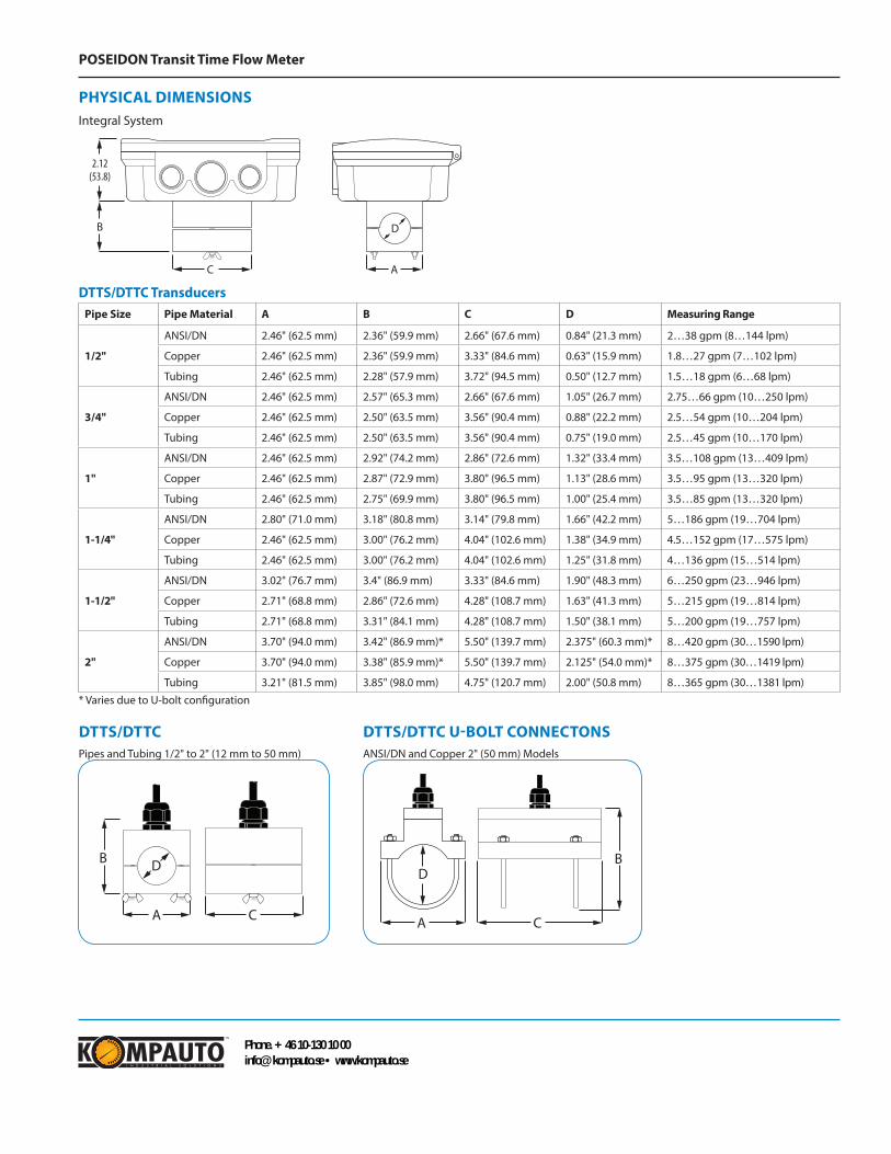
DTTS/DTTC U-BOLT CONNECTONSANSI/DN and Copper 2" (50 mm) Models
DTTS/DTTC TransducersPipe Size Pipe Material A B C D Measuring Range
1/2"
ANSI/DN 2.46" (62.5 mm) 2.36" (59.9 mm) 2.66" (67.6 mm) 0.84" (21.3 mm) 2…38 gpm (8…144 lpm)
Copper 2.46" (62.5 mm) 2.36" (59.9 mm) 3.33" (84.6 mm) 0.63" (15.9 mm) 1.8…27 gpm (7…102 lpm)
Tubing 2.46" (62.5 mm) 2.28" (57.9 mm) 3.72" (94.5 mm) 0.50" (12.7 mm) 1.5…18 gpm (6…68 lpm)
3/4"
ANSI/DN 2.46" (62.5 mm) 2.57" (65.3 mm) 2.66" (67.6 mm) 1.05" (26.7 mm) 2.75…66 gpm (10…250 lpm)
Copper 2.46" (62.5 mm) 2.50" (63.5 mm) 3.56" (90.4 mm) 0.88" (22.2 mm) 2.5…54 gpm (10…204 lpm)
Tubing 2.46" (62.5 mm) 2.50" (63.5 mm) 3.56" (90.4 mm) 0.75" (19.0 mm) 2.5…45 gpm (10…170 lpm)
1"
ANSI/DN 2.46" (62.5 mm) 2.92" (74.2 mm) 2.86" (72.6 mm) 1.32" (33.4 mm) 3.5…108 gpm (13…409 lpm)
Copper 2.46" (62.5 mm) 2.87" (72.9 mm) 3.80" (96.5 mm) 1.13" (28.6 mm) 3.5…95 gpm (13…320 lpm)
Tubing 2.46" (62.5 mm) 2.75" (69.9 mm) 3.80" (96.5 mm) 1.00" (25.4 mm) 3.5…85 gpm (13…320 lpm)
1-1/4"
ANSI/DN 2.80" (71.0 mm) 3.18" (80.8 mm) 3.14" (79.8 mm) 1.66" (42.2 mm) 5…186 gpm (19…704 lpm)
Copper 2.46" (62.5 mm) 3.00" (76.2 mm) 4.04" (102.6 mm) 1.38" (34.9 mm) 4.5…152 gpm (17…575 lpm)
Tubing 2.46" (62.5 mm) 3.00" (76.2 mm) 4.04" (102.6 mm) 1.25" (31.8 mm) 4…136 gpm (15…514 lpm)
1-1/2"
ANSI/DN 3.02" (76.7 mm) 3.4" (86.9 mm) 3.33" (84.6 mm) 1.90" (48.3 mm) 6…250 gpm (23…946 lpm)
Copper 2.71" (68.8 mm) 2.86" (72.6 mm) 4.28" (108.7 mm) 1.63" (41.3 mm) 5…215 gpm (19…814 lpm)
Tubing 2.71" (68.8 mm) 3.31" (84.1 mm) 4.28" (108.7 mm) 1.50" (38.1 mm) 5…200 gpm (19…757 lpm)
2"
ANSI/DN 3.70" (94.0 mm) 3.42" (86.9 mm)* 5.50" (139.7 mm) 2.375" (60.3 mm)* 8…420 gpm (30…1590 lpm)
Copper 3.70" (94.0 mm) 3.38" (85.9 mm)* 5.50" (139.7 mm) 2.125" (54.0 mm)* 8…375 gpm (30…1419 lpm)
Tubing 3.21" (81.5 mm) 3.85" (98.0 mm) 4.75" (120.7 mm) 2.00" (50.8 mm) 8…365 gpm (30…1381 lpm)
* Varies due to U-bolt configuration
Integral System
Remote System
C
2.12(53.8)
B
A
D
C
B
D
Pipe mountWall mountA A
B
CDIA Mounting
holes (2)
B
C
DTTS/DTTC U-Bolt ConnectionsANSI/DN & Copper 2" (50 mm) Models
DTTN/DTTH/DTTLPipes larger than 2" (50 mm)
DTTS/DTTCPipes/Tubing ½" to 2" (12 mm to 50 mm)
DTTN 2.95 2.75 3.00 (74.9) (69.8) (76.2)DTTH
DTTL
2.95 2.75 3.00 (74.9) (69.8) (76.2)
3.40 2.94 3.20 (86.4) (74.7) (81.3)
A B CA
B
C (Min Clearance)
BB
A
D D
C A C
A
TOP VIEWOF PIPE
DTTS/DTTCPipes and Tubing 1/2" to 2" (12 mm to 50 mm)
Integral System
Remote System
C
2.12(53.8)
B
A
D
C
B
D
Pipe mountWall mountA A
B
CDIA Mounting
holes (2)
B
C
DTTS/DTTC U-Bolt ConnectionsANSI/DN & Copper 2" (50 mm) Models
DTTN/DTTH/DTTLPipes larger than 2" (50 mm)
DTTS/DTTCPipes/Tubing ½" to 2" (12 mm to 50 mm)
DTTN 2.95 2.75 3.00 (74.9) (69.8) (76.2)DTTH
DTTL
2.95 2.75 3.00 (74.9) (69.8) (76.2)
3.40 2.94 3.20 (86.4) (74.7) (81.3)
A B CA
B
C (Min Clearance)
BB
A
D D
C A C
A
TOP VIEWOF PIPE
PHYSICAL DIMENSIONSIntegral System
Phone. +46 10-130 10 [email protected] • www.kompauto.se

![Sontex Energy Meter - Belimo05.08.2009.UPDATE].pdf · Subject to technical changes V1.1 1102009 Thermal energy meter Superstatic 440 + Supercal 531 + Temperature sensor Energy Meter](https://img.dokumen.tips/doc/110x75/5abf072d7f8b9add5f8d4a41/sontex-energy-meter-05082009updatepdfsubject-to-technical-changes-v11-1102009.jpg)