Embed Size (px)
Citation preview

T
N
ERa
b
a
ARRAA
KNSASGMH
1
aarsst
aialWtiIr
T
b(
h0
Precision Engineering 45 (2016) 463–468
Contents lists available at ScienceDirect
Precision Engineering
jo ur nal ho me p age: www.elsev ier .com/ locate /prec is ion
echnical note
on-contact position control via fluid shear force
dward Sunga,∗, Brandon Chalifouxa, Jay Fucetolaa, Mark L. Schattenburgb,alf K. Heilmannb
Department of Mechanical Engineering, Massachusetts Institute of Technology, 70 Vassar St. 37-276, Cambridge, MA 02139, USASpace Nanotechnology Lab, MIT Kavli Institute, 70 Vassar St. 37-276, Cambridge, MA 02139, USA
r t i c l e i n f o
rticle history:eceived 21 February 2014eceived in revised form 8 February 2016ccepted 25 February 2016vailable online 11 March 2016
eywords:
a b s t r a c t
Non-contact position control of components is beneficial to avoid wear, damage, and nonlinearities asso-ciated with friction. Air bearings, in particular, offer non-contact, high stiffness guidance, but no means ofcontrolling the position of the supported component. In this work, we investigate the use of shear forceresulting from the air bearing fluid flow as a means of actuation. Shear force actuation is tested in anair bearing slumping system, where a flat, horizontally placed glass substrate is supported on both sidesby top and bottom air bearings. We investigate the use of two methods of substrate position sensing: afiber-optic sensor and a machine vision sensor. We show that the glass substrate position can be success-
on-contacthear forceir bearinglumpinglassachine vision
fully controlled by using fluid shear force. The magnitude of the fluid shear force is measured. Systemidentification is performed, and the results are shown to agree with a second-order model.
© 2016 Elsevier Inc. All rights reserved.
igh temperature
. Introduction
Frictionless mechanical elements and actuators are highly desir-ble in precision machines, where nonlinearity and hysteresisrising from friction can have a significant impact on positioningepeatability and accuracy. While frictionless guidance elements,uch as flexures, magnetic bearings, and air bearings, can guidetructures with excellent repeatability, the actuators themselvesypically introduce friction and stress concentrations.
Air bearings are generally used with gaps smaller than 10 �mnd provide nearly frictionless bearings [1]. Viscous forces are dom-nant over inertial forces in thin, long gaps in which the lubricationpproximation is valid [2]. In lubrication flows, the fluid can supportarge loads and impart significant shear force on the object surface.
hen a planar air bearing is perfectly parallel to an object surface,he pressure distribution, and therefore the flow, of the fluid film
s radially symmetric, so there is no net shear force on the surface.f a wedge angle is imparted, the shear forces become asymmet-ic due to a shifting pressure distribution [3], and a net shear force∗ Corresponding author at: 1101 S Main St Apt 310, Milpitas, CA 95035, USA.el.: +1 650 630 8829
E-mail addresses: [email protected] (E. Sung),[email protected] (B. Chalifoux), [email protected] (J. Fucetola), [email protected]. Schattenburg), [email protected] (R.K. Heilmann).
ttp://dx.doi.org/10.1016/j.precisioneng.2016.02.017141-6359/© 2016 Elsevier Inc. All rights reserved.
arises. This concept is shown in Fig. 1, and has been modeled inRef. [4]. Since this shear force is applied over the entire surface,stress concentrations are avoided. Devitt et al. [5] have reportedusing shear force as an actuation method for flexible films movingover cylindrical air bearings, to control tension of the film and toprovide increased cooling, cleaning and drying of the film. van Rijet al. [6] and van Ostayen et al. [7] have used shear stress to controlwafer position, by implanting an air bearing with many cells whosepressures may be independently controlled. This allows control ofthe direction of flow. The same effect may be achieved more simply,for our purposes, by wedging a top and bottom air bearing with thewafer in between, which is the method investigated in this work.
The motivation for the present work is to investigate the useof fluid shear force for actuation in a non-contact glass slumpingdevice using air bearings, which is to be used in the fabrication ofhigh-precision thin optics for X-ray telescopes. In this application,a flat, round glass substrate floats between two porous air bear-ings, and, as the device and glass are heated, the glass softens andconforms to the figure of the air bearings. The method of actuationresearched by van Rij et al. [6] and van Ostayen et al. [7] cannot beused for slumping, because the softened glass at high temperatureswill droop and touch the bearing, if it is not supported on both sides
symmetrically.Position control is required because the glass is in an unstableequilibrium. It is critical to have non-contact position actuation andsensing, which does not induce stress concentrations, in order to

464 E. Sung et al. / Precision Engineering 45 (2016) 463–468
aetbHs
diaiGbostublaingmt
2
tga(unt
F
the inner ring and bearing/plenum combination each providesrotation about a quasi-horizontal axis (x and z axes). Threecapacitance sensors (HPT-150F-V-N2-3-B “V” series probes from
Fig. 1. Illustration of net shear force arising from wedge angle, ˛.
void introducing deformations in the glass, which can arise fromven small concentrated forces while the glass is soft. For example,he simplest method to keep the glass centered in between the twoearings would be to add a physical stop around the circumference.owever, it was discovered that any such physical stop, which is a
mall concentrated force, induces ripples in the glass geometry.Non-contact slumping offers a distinct advantage over tra-
itional contact slumping: mid-spatial frequency errors are notntroduced. In contact slumping, glass is placed on a mandrel, with
release layer between the two (to prevent the glass from fus-ng to the mandrel), and heated to the softening point of the glass.ravity forces the glass to conform to the figure of the mandrel,ut any non-uniformity of the release layer, due to either clumpingr dust particles, introduces mid-spatial frequency errors in thelumped glass. These errors adversely affect the angular resolu-ion of X-ray telescopes, and are difficult or impossible to removesing figure correction techniques [8]. Non-contact slumping on airearings avoids this issue by replacing the solid or powder release
ayer with an air film. In addition to not introducing ripples, thisir film allows significantly faster slumping cycles since the glasss not in contact with a mandrel, which is a large mass with a sig-ificantly different coefficient of thermal expansion than that oflass. A long cool-down time, on the order of days, is required toinimize figure errors due to this mismatch in the coefficients of
hermal expansion.
. Slumping device prototype design
Investigating the use of shear force as a means of position con-rol requires a device with air bearings capable of supporting alass substrate and imparting a controllable wedge angle to gener-te shear forces. The device shown in Figs. 2–4 is a non-slumpingroom temperature) prototype that is meant to only validate the
sage of fluid shear force as an actuator. This initial device does noteed to actually slump glass, so it does not need to withstand highemperatures. Although the method of position sensing used in theig. 2. Photo of device used to control glass position between two air bearings.
Fig. 3. Cross-sectional view of the device in a perfectly stable position.
600 ◦C application is presented in Section 2.2, the complete designof the final slumping (high temperature) device is not presented inthis paper.
2.1. Mechanical design
The slumping device, described in detail by [9], can be dividedinto two subassemblies, top and bottom, which are mated togetherthrough an adjustable kinematic coupling (KC). The purpose of thekinematic coupling is to enable repeatable positioning of the sub-assemblies with respect to each other after removal of the topassembly for maintenance. Each subassembly holds a porous airbearing and a plenum chamber. The two air bearings face eachother with a tightly controlled gap, in which a substrate is placed.The bottom subassembly stays stationary and provides the bottomsupport for the substrate. The top subassembly works as a 2-axisgimbal to angle the top air bearing in relation to the bottom bearingto provide a directed shear force.
Fig. 5 illustrates the exaggerated kinematics of the top sub-assembly. The outer ring mates to the bottom subassembly usingthe KC adjuster screws, which rest in the KC grooves on thebottom subassembly. The outer ring remains stationary, while
Capacitec) are mounted to the bottom subassembly, and provide
Fig. 4. Cross-sectional view of the device illustrating rotation of the top bearing toimpart a shear force.

E. Sung et al. / Precision Engineering 45 (2016) 463–468 465
bbbofora
asl
2
iaiw(ubbo
F
Fig. 5. Top subassembly of device with exaggerated movements.
earing-to-bearing gap distances at 3 points to calculate the overallearing-to-bearing angle. These capacitance sensors were cali-rated to have a resolution of 87.5 nm with a measurement rangef 2.5 mm. Two stack-type piezoelectric actuators (P/N PA100/T14rom Piezosystem Jena), which are mounted on the inner ring, pushn the outer ring and the bearing/plenum separately to provide theotational movements. They feature a range of motion of 105 �m,nd a resolution of 0.21 nm.
Machined porous aluminum is used as the air bearing material,nd the bearings are lightly held to the plenums with screws andealed around the edges using adhesives. The plenum pressure isimited to about 1 psi to minimize bowing of the bearing.
.2. Fiber-optic sensor
A fiber optic sensor, described in detail in Ref. [9] and shownn Fig. 6, was developed to provide substrate position feedback innticipation of using this sensor at temperatures suitable for slump-ng (i.e. 600 ◦C). 15 mW of 850 nm wavelength light is fed into a fiber
ith a 500 �m core diameter, and is directed normal to the edgecylindrical surface) of the substrate. The reflected light is picked
p by another fiber located next to the source fiber, and is detectedy a silicon photodetector. The reflected light intensity is found toe an exponential function of distance, as shown in Fig. 6. The rangef the usable signal is 3–10 mm from the ends of the fibers.ig. 6. Fiber sensor concept for glass position measurement, and measured reflected intens
Fig. 7. Schematic of machine vision glass position measurement system.
The main limitation of this sensor is its sensitivity to edgedefects. Glass wafers are typically only polished on the flat sur-faces and have highly irregular edge surfaces. Thus, as the wafertranslates or spins, the light that reflects off the edge and intothe detection fiber fluctuates heavily, introducing significant noise.With heavy low-pass filtering, this sensor was found to be sufficientfor coarse position control at high temperature [9], but insuffi-cient for characterization of the shear force. For the purposes ofcharacterization of the shear force, a machine vision system wasimplemented, as described in Section 2.3. However, in a high tem-perature slumping device, which operates at 600 ◦C, the fiber opticsensor is used instead of the machine vision system.
2.3. Machine vision
Machine vision was implemented as a better method of positionmeasurement at room temperature. The glass substrate is backlit
with a cold cathode tube diffuse light source along two axes, andthe position measured with a CCD camera in each axis, as shown inFig. 7. The image is dark where the glass blocks the light, and it isbright elsewhere. To determine the edge position of the glass, weity as a function of distance from fiber. Measurements taken under static conditions.

466 E. Sung et al. / Precision Engineering 45 (2016) 463–468
system
fif
ipntaap
3
osTshawtPtscatomt
3
Tbtpp
tocastg
When the slumping device is well-leveled and the wedge angleis zero, the glass substrate finds an equilibrium position, con-trary to our previous statement that the system has an unsteady
Fig. 8. Block diagram of
nd the peak of the cross-correlation between the image and a stepunction. This reliably located the edge to the nearest whole pixel.
The range of this position measurement is approximately 25 mmn each axis, and the glass position resolution is around 75 �m (1ixel). With this system, the edge quality of the glass introduceso significant noise; the noise is less than 1 pixel. Reliable posi-ion measurements of sufficient accuracy for our application werechieved with this system, so it was used for the shear force char-cterization and transfer function measurement described in thisaper.
. Experimental
The experimental objectives were to: (1) understand the naturef the shear force and measure its magnitude; and (2) to under-tand the system dynamics and measure the frequency response.he shear force is found to vary linearly with wedge angle. Mea-uring the magnitude of this force is important for understandingow well the glass position can be controlled by this force. Inll of these experiments, the position of the glass was controlledith a PID controller, using the machine vision system for posi-
ional feedback. Based on the feedback of the machine vision, aID-controlled voltage was outputted to the piezo-electric actua-ors, which changed the wedge angle, thus creating a directed fluidhear force on the glass. The PID controller used for glass positionontrol was not optimized, but provided glass position stability tollow a frequency response measurement. Section 3.3 discusseshe frequency response measurement of the system. The controllerperates at a sampling frequency of 40 Hz, and the response is atost 1 Hz. Fig. 8 shows a block diagram of the system, including
he PID input.
.1. Shear force measurement
The purpose of this experiment was to measure the shear force,, as a function of wedge angle, ˛. The average gap between eachearing and the glass was held constant at 30 �m (minimum dis-ance from center of bearing to glass). While smaller gaps wouldrovide higher fluid shear force, we chose a larger gap in order toerform the experiments over a larger wedge angle.
The position of the glass was held constant near the center ofhe bearings using PID control, and the entire assembly was tiltedver a range of ±800 �rad from horizontal as measured by a pre-ision bubble level. As the tilt angle increases, the wedge angle
lso increases, in order to create a greater fluid shear force. Theteady state wedge angle between bearings was measured usinghe capacitance sensors. At the steady state wedge angle, ˛, for aiven tilt angle �, the glass is in static equilibrium, and the shearwith PID control loop.
force at this wedge angle is equal to the component of the gravita-tional force parallel to the glass sheet:
T = mglass ∗ g ∗ sin(�) (1)
The measurements from the experiment gave us the relationshipbetween ̨ and �, and substituting into Eq. (1), we can further for-mulate the relationship between T and ˛. As shown in Fig. 9, theshear force is a linear function of wedge angle, and is measured as:
T = [0.54 �N/�rad] ̨ (2)
Data from [5] suggest a shear force constant around 50 �N/�rad,for a flat graphite bearing at 60 psi plenum pressure. However, theexperimental setup of [5] is very different from the present study inthat, in [5], the “bottom bearing” is actually an air bearing roller, andthe “substrate” is a thin sheet of plastic contrained by 3 rollers. Theflat graphite bearing was pressed against a round surface, whichdoes not provide a large flat surface – only a relatively small surfacearea would be effective in providing a shear force. In addition, ourplenum pressure is much lower (1 psi), so a direct comparison ofour results is invalid. Thus we mention this information only as arough verification that our measurements appear to be in a similarregime.
3.2. Spring constant measurement
Fig. 9. Measured shear force as a function of wedge angle, ˛.
ngineering 45 (2016) 463–468 467
eolffr(jbcti
cgebe
cTgmmgbt
F
Ta
E. Sung et al. / Precision E
quilibrium. As the bearings are held constant with respect to eachther, and the entire assembly is tilted, the position of static equi-ibrium changes, and the change in position is proportional to theorce applied to it (in this case, misalignment with gravity): a springorce. The spring force is relatively small, however, and cannot beelied upon to keep the glass in position under changing conditionsi.e. thermal expansions during ramp-up to 600 ◦C). Even a tilt ofust 0.5◦ will cause the wafer to fall/slide out from between theearings. This behavior is also observed when the tilt angle is keptonstant but the wedge angle is varied (as we saw in Section 3.1,his also changes the force applied to the glass). This phenomenons not yet fully understood.
The purpose of this experiment was to measure the springonstant of the system. While in the previous experiment, thelass position was the variable that was held constant, in thisxperiment, it is the wedge angle that was held constant. That isecause the effect of shear force via a wedge angle needed to beliminated.
The glass position controller was turned off, and the wedge angleontroller was commanded to maintain a constant wedge angle.he machine vision camera was left on to record the position of thelass. The entire assembly was tilted, and the inclination angle waseasured with precision levels. At each inclination angle, the glassoves to a new equilibrium position, where the spring force and
ravitational forces are equal. The relationship for spring force cane substituted into Eq. (1) in order to relate the spring force to theilt angle:
spring = k ∗ x = mglass ∗ g ∗ sin(�) (3)
he data in Fig. 10 shows that position is a linear function of tiltngle. The spring constant is found to be very small: 18.46 �N/mm.
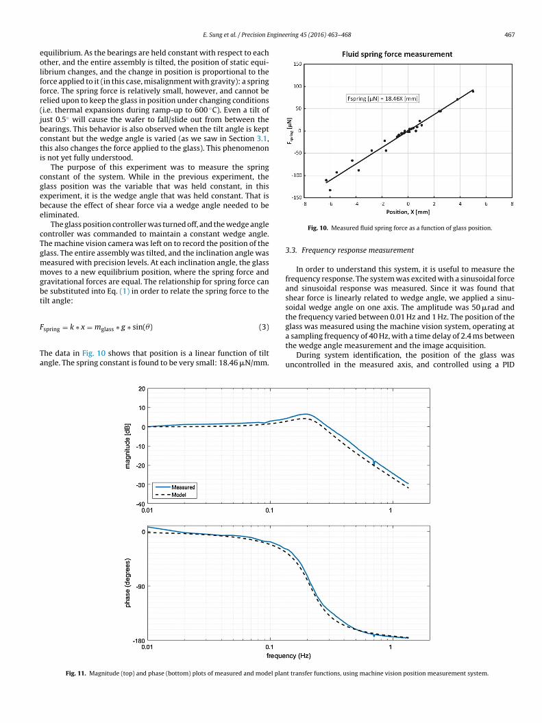
Fig. 11. Magnitude (top) and phase (bottom) plots of measured and model plan
Fig. 10. Measured fluid spring force as a function of glass position.
3.3. Frequency response measurement
In order to understand this system, it is useful to measure thefrequency response. The system was excited with a sinusoidal forceand sinusoidal response was measured. Since it was found thatshear force is linearly related to wedge angle, we applied a sinu-soidal wedge angle on one axis. The amplitude was 50 �rad andthe frequency varied between 0.01 Hz and 1 Hz. The position of theglass was measured using the machine vision system, operating at
a sampling frequency of 40 Hz, with a time delay of 2.4 ms betweenthe wedge angle measurement and the image acquisition.During system identification, the position of the glass wasuncontrolled in the measured axis, and controlled using a PID
t transfer functions, using machine vision position measurement system.

4 nginee
crqT
3
t
G
wrmat
ω
wpw
btsfdff
b
wiT(sgsmspTt
4
dcaigmrbbtih
[
[[
[
[
[
[
68 E. Sung et al. / Precision E
ontroller in the orthogonal axis. The magnitude and phase of theesponse is measured using 10–100 excitation cycles at each fre-uency, and the frequency response generated as shown in Fig. 11.he model shown is discussed in Section 3.4.
.4. Dynamic system model
This system can be represented by a mass-spring-damper sys-em with a time delay, with a two-pole transfer function:
(s) = xglass(s)˛(s)
= G(0)ω2n
s2 + 2ωn�s + ω2n
e−�delays (4)
here s is the frequency variable (in this case, s = jω), ωn is the natu-al frequency, � is the damping ratio, �delay is a time delay betweeneasurements of input (wedge angle) and output (glass position),
nd G(0) is the static response. These parameters can be related tohe mass, viscous friction, and spring constant of the system:
n =√
k
m, � = b
2√
km, G(0) = x
˛= T/k
˛(5)
here k is the spring constant, m is the mass, b is the viscous frictionarameter, and T is the static shear force on the glass due to bearingedging, and was found in Section 3.1.
The viscous friction arises from Couette flow [2] between theearings and the glass, due to the movement of the glass rela-ive to the stationary bearings. Since the system is linear, the nethear force on the glass is a superposition of the force arisingrom the position-dependent force (spring force), the wedge-angle-ependent force (excitation force), and the velocity-dependentorce (Couette flow). The viscous friction parameter, b, is computedrom:
= 2A�
h(6)
here A is the surface area of the glass, � is the dynamic viscos-ty of the air, and h is the gap between the glass and bearings.he viscous friction parameter for nitrogen at room temperature� = 1.76 × 10⁻⁵ Pa s), a gap of 30 �m, and a 100 mm diameter sub-trate is found to be 9.2 × 10⁻³ N s/m, according to Eq. (6). Thelass substrate mass is measured to be 10.8 g. The spring force con-tant arises from the phenomena discussed in Section 3.2, and iseasured to be 18.46 �N/mm. The shear force constant is mea-
ured in Section 3.1 to be 0.54 �N/�rad. From these four physicalarameters, ωn = 1.33 rad/s, � = 0.32, and G(0) = 0.0294 mm/�rad.his modeled transfer function is plotted along with the measuredransfer function in Fig. 11.
. Discussion
This system can adequately be described by mass-spring-amper system. The mass and viscous friction components arelear, but the cause of the spring phenomenon is not known. It mayrise because the glass position affects the flow field in the bear-ng, since the glass does not completely cover the bearing. As thelass moves to one side, the flow on the other side of the bearingay increase, dragging more fluid toward that side, and providing a
estoring force. This spring-like behavior was observed only whenoth bearings were present. If the glass is floating on the bottom
earing only, then the glass position is unstable. It is also clear thathe spring force does not arise from a varying wedge angle, becausen the experiment described in Section 3.2, the wedge angle waseld constant, but the restoring force was observed.[
[
ring 45 (2016) 463–468
The tolerance in the measurement of magnitude and phase dur-ing each experimental run is quite low, since at least 10 cycleswere used for all frequencies. As the frequency increased and theresponse magnitude decreased, more cycles were used in calculat-ing the response magnitude and phase. For example, at frequenciesnear 1 Hz, the amplitude of the response was only around 2 pixels,which would not have given an accurate measurement normally.To overcome this resolution limitation, the wafer pixel position wasaveraged over numerous cycles to gain a statistical measurementof position.
There is uncertainty in the plenum pressure used, due to leak-ages through the bearing and plenum mating surfaces. This makesthe variation of shear force due to plenum pressure difficult tocharacterize. The tolerance in the gap between the bearings andglass is ±5 �m due to capacitance sensor accuracy and wafer thick-ness measurement accuracy. This also limits our ability to study thevariation of shear force with bearing gap.
5. Conclusions
In this work, we have demonstrated the use of shear force asa method of actuation to control the position of a flat glass sub-strate between two flat air bearings. The magnitude of the shearforce has been quantified, and found to be linearly related to thewedge angle. In addition, the frequency response of the system hasbeen measured, and shown to agree with a two-pole system modelconsisting of a mass, spring, and damper.
While the frequency response indicates that fast position con-trol is not possible with the current design (e.g. low pressure), thisis sufficient for control of a glass substrate during slumping, wherethe goal is to keep the glass stationary to within about 1 mm. Atroom temperature, our control system maintains position to lessthan ±0.1 mm. In practice, the ability of the controller to main-tain the glass position has been limited by the sensor noise. Forother applications, there are other ways that shear force mightbe implemented. For example, air bearings supporting a stage orobject could be tilted to provide a shear force, or a set of air bearingsdedicated to providing shear force can be used.
Acknowledgement
The authors thank NASA grant NNX10AF59G for supporting andfunding this research.
References
1] Slocum AH. Precision machine design. 1st ed. Michigan: Society of Manufactur-ing Engineers; 1992. p. 421–625.
2] Panton RL. Incompressible flow. 3rd ed. New Jersey: Wiley; 2005.3] Rao NS. Analysis of aerostatic porous rectangular thrust bearings with offset
loads. Wear 1980;59:333–44.4] Husseini A [MS Thesis] Design and Modeling of a Third Generation Slumping
Tool for X-ray Telescope Mirrors. Massachusetts Institute of Technology; 2011,June.
5] Devitt D, Allen J. Viscous shear in air bearings gaps for precise web tension andtemperature control. Proc ASPE 2012.
6] van Rij J, Wesselingh J, van Ostayen R, van Eijk J. Planar wafer transportand positioning on an air film using a viscous traction principle. Tribol Int2009;42:1542–9.
7] van Ostayen R, van Eijk J, Schmidt RHM. Contact-less thin substrate transportusing viscous traction. Design, control, and software implementation for dis-tributed MEMS (dMEMS). In: 2012 Second Workshop. 2012. p. 14–21.
8] Zhang W, Chan KW, McClelland RS, O’Dell SL, Saha TT. Next generationX-ray optics: high-resolution, light-weight, and low-cost. Proc SPIE 2012;8443.
9] Sung E [MS Thesis] Horizontal Non-contact Slumping of Glass. MassachusettsInstitute of Technology; 2013, May.