Embed Size (px)
Citation preview

ARTICLE IN PRESS
JOURNAL OFSOUND ANDVIBRATION
0022-460X/$ - s
doi:10.1016/j.js
�CorrespondE-mail addr
1Presently at2Presently at
Journal of Sound and Vibration 297 (2006) 492–511
www.elsevier.com/locate/jsvi
Noise reduction in a flow duct: Implementationof a hybrid passive/active solution
N. Sellen1, M. Cuesta2, M.-A. Galland�
Laboratoire de Mecanique des Fluides et d’Acoustique UMR CNRS 5509, Ecole Centrale de Lyon, 69134 Ecully Cedex, France
Received 16 May 2005; received in revised form 20 March 2006; accepted 30 March 2006
Available online 21 June 2006
Abstract
This paper deals with the design of a hybrid acoustic treatment combining porous material properties and active control
techniques. Such an acoustic system was studied with a view to reducing broadband noise spectra in flow duct applications.
Special attention was paid to the selection of the passive layer. The main objective was to achieve target impedance at the
front absorber face, so as to attain maximum sound-attenuation over a wide frequency bandwidth. This investigation was
carried out for a specific laboratory flow duct. Different porous layers were studied to reproduce optimum impedance at
the hybrid liner surface. Results showed the difficulty of simultaneously achieving optimum resistance and reactance. Thus,
a compromise was struck by applying a criterion of maximum attenuation. A wire mesh with a resistance close to a third of
the characteristic impedance of air was selected as the optimal passive layer. Experiments were carried out in the flow duct
under grazing acoustic incidence and with flow velocities up to 50m/s. The experimental transmission loss was in
agreement with predictions. Significant noise reduction levels were achieved throughout a large frequency range from 0.7
to 2.5 kHz, with a cut-off frequency between active and passive mode set at 1.8 kHz.
r 2006 Elsevier Ltd. All rights reserved.
1. Introduction
The recent development of automotive and aircraft transport has contributed to the emergence of a newkind of nuisance: noise pollution. In aeronautics in particular, ever more severe regulations have been drawnup by the International Civil Aviation Organization (ICAO). Acoustic certification procedures have thus beenintroduced, imposing noise restrictions, leading to the setting up of many European and American aircraftnoise reduction research programs. An important contribution comes from turbo engines—and more preciselyfrom the fan, in the specific case of modern high bypass-ratio engines. This noise spectrum is characterised bypure tones (BPF and its harmonics) over a broadband component, both depending on the operating regime ofthe turbo engine. Noise can be reduced by certain absorbent treatments applied to the nacelle walls.
ee front matter r 2006 Elsevier Ltd. All rights reserved.
v.2006.03.049
ing author. Tel.: +33 0 4 72 18 60 13; fax: +33 0 4 72 18 91 43.
ess: [email protected] (M.-A. Galland).
SNECMA Moteurs, Site de Villaroche, Departement Acoustique, 77550 Moissy-Cramayel, France.
Instituto de Acustica, Consejo Superior de Investigaciones Cientificas (CSIC), Madrid, Spain.
ARTICLE IN PRESSN. Sellen et al. / Journal of Sound and Vibration 297 (2006) 492–511 493
The present study concerned the design of a new kind of liner, to limit fan noise propagating in the turboengine inlet. This acoustic treatment consists of a hybrid absorbent cell, combining passive properties of aporous material and active control to ensure pressure cancellation at the rear face of the porous sheet. Thehybrid absorption concept refers to the double operation of the cell: active at low and passive at higherfrequencies. Such an acoustic system is intended to enlarge the frequency bandwidth treated, compared toexisting acoustic liners. Conventional passive treatments (single degree of freedom: sdof; 2 degrees of freedom:2dof) afford high attenuation levels over a rather narrow frequency range, while purely active technologiesappear to be effective mainly at low frequencies.
The notion of active absorption was firstly introduced by Olson and May [1] who proposed an electronic
sound absorber providing pressure release on the back face of a resistive sheet. In the 1980s, Guicking andLorenz [2] validated this concept experimentally. Many investigations have sought to implement hybridabsorption technology, leading to patent applications [3]. Thenail [4] and Furstoss [5] developed an activetreatment composed of a glass wool layer backed by an air cavity closed through an active surface. Beyene andBurdisso [6] achieved active boundary conditions by means of impedance adaptation in a porous rear facelayer. Recently, Cobo et al. [7] demonstrated the feasibility of designing thinner hybrid passive/activeabsorbers using microperforated panels rather than the conventional porous materials.
For aeronautic applications, many constraints related to the hostile nacelle environment have to be takeninto account to manufacture a reliable and resistant hybrid liner. Among the mechanical, climatic andgeometrical constraints, treatment performance has to integrate weight, shape and reliability factors as well aseasy replacement of the absorbent cells in case of damage. Initial broadband noise spectrum reduction studieswere run by the Centre Acoustique du LMFA, Ecole Centrale de Lyon in the framework of the EuropeanRANNTAC (Reduction of Aircraft Noise by Nacelle Treatment and Active Control) and RESOUND(Reduction of Engine Source Noise through Understanding and Novel Design) projects. An active absorbentcell composed of a resistive layer backed by an active control module was developed and validated undernormal acoustic incidence. Further experiments by Galland [8] and [9] on a flow duct under grazing acousticincidence led to pressure reductions up to 10 dB outside the test bench. Several resistive layers were moreoverapplied to the cell’s front face, enabling power reduction up to 12 dB in the no-flow configuration.
The present study concerns the European SILENCER (Significantly lower community exposure to aircraftnoise GRD1-2000-25297) programme, which seeks to design new technologies ensuring attenuation ofperceived aircraft noise. As acoustic treatments are generally characterised by their surface impedance, thehybrid active/passive liner has been specifically developed to reach a pre-targeted impedance on the frontabsorber face. The goal of the present investigation was to optimise the hybrid acoustic treatment in the moregeneral case of flow duct applications. A specific experimental set-up was designed to further estimate andvalidate the proposed strategy. Both the active and passive components of the hybrid liner were optimised toachieve maximum noise reduction in the laboratory. The present paper focuses on the passive layeroptimisation. The complementary active control system has been analysed in Refs. [10,11]. Promisingattenuation results were obtained with the hybrid absorbent cells [12].
Both the general description of a hybrid passive/active absorber and the procedure to optimise the proposedhybrid cell are available in Section 2. The characteristics of the optimum impedance of such a liner and thetheoretical approach to implement it are presented in Sections 3 and 4, respectively. Finally, the effectivenessof the hybrid technology under grazing acoustic incidence is experimentally demonstrated in Section 5.
2. Hybrid cell optimisation procedure
The basic principle of the active absorber was previously described and validated in Ref. [5]. It results fromthe low-frequency behaviour of a porous material, which mainly depends on its flow resistance R or itsresistivity s as follows:
R ¼P1 � P2
V¼ se, (1)
where e is the thickness of the porous sample, and V the velocity of the air flow through the material due to thepressure gradient DP ¼ P1 � P2. When the acoustic pressure P2 at the rear porous sheet face is cancelled, the

ARTICLE IN PRESSN. Sellen et al. / Journal of Sound and Vibration 297 (2006) 492–511494
material surface impedance Z ¼ P1=V becomes proportional to resistivity (2)
Z ¼P1
V¼ se. (2)
Under such conditions, i.e. P2 ¼ 0, the surface impedance, or more precisely the surface resistance, of a givenporous medium can easily be controlled with a suitable thickness e. For instance, the maximal absorption incase of normal incidence is reached for a purely real impedance equal to the characteristic impedance of air Z0.The acoustic pressure on the rear porous sheet face can be cancelled, placing the material at a quarter of awavelength from a rigid wall. This technique is commonly used to design conventional passive treatments.Such methods nevertheless present many drawbacks, since the frequency range in which the pressure release isachieved remains quite narrow. Moreover, at low frequencies, the air gap behind the porous material becomesrather significant (for instance: at 500Hz, l=4 ¼ 0:17m). However, the pressure release condition behind thematerial can be also provided by an active control system composed of a secondary source, a controller and acontrol microphone, as suggested by Olson [1].
A hybrid active/passive liner can therefore be achieved by connecting hybrid cells (see Fig. 1), eachcomprising a porous layer backed by an active control system. The main advantage of such a hybrid treatmentis to absorb over a wider frequency bandwidth without increasing system bulk. The hybrid operation can besummarised as follows: at low frequencies, the active control on the rear material face is turned on (active
functioning mode), ensuring the pressure release condition (see Fig. 2(a)). Thus, the surface impedance of theporous layer becomes purely resistive, and is governed by the resistivity of the medium. In the higherfrequency range, the active control system is turned off (passive functioning mode) and the porous layer istherefore backed by an air cavity of optimised depth (see Fig. 2(b)).
This treatment appears to be well suited to flow duct applications, even in the active functioning mode, sincethe active part is protected from the flow by the porous layer. The objective of this study was to define, buildand test an active/passive liner optimised for a dedicated laboratory flow duct. The MATISSE test bench(Fig. 3) consisted of a 3.20m long square cross-section duct ð66� 66mm2Þ with anechoic termination. Suchsmall transverse dimensions led to a large plane wave analysis up to approximately 2.5 kHz in the flow duct. Asilent flow generator at the upstream extremity induced mean flow velocities up to 50m/s. The acoustic sourcewas mounted on the upper wall, upstream of the acoustic treatment. The liner of finite length was assumed tobe locally reacting, and could be applied either on the upper wall or on both opposite walls of the duct.
The optimal hybrid absorbent cell for MATISSE was implemented following the global optimisationprocedure described in Fig. 4. First, the optimum impedance to be reached at the input of the hybrid liner wascharacterised. Then, a theoretical study concerning the parallel optimisation of both passive and active
Fig. 1. The hybrid active/passive treatment.
Fig. 2. Hybrid active/passive functioning modes of the acoustic absorbent cell: (a) at low frequencies: active mode and (b) at high
frequencies: passive mode.

ARTICLE IN PRESS
Fig. 3. MATISSE flow duct.
1. Optimal impedance calculation
2. Theoretical study of the prototype
3. Experimental validation
Standing wave tube measurements : normal incidence
Grazing acoustic measurements on MATISSE flow duct : TL, IL...
Passive part optimization
•
Selection of the optimal passive layer
surface impedance
to achieve target impedance
• Cell geometry
• Actuator
• Control microphone
• Control algorithm
Achievement of the pressurecancellation boundary condition
• to achieve high attenuation levels
• Existing materials• Multilayer configurations
Active part optimization
Fig. 4. Hybrid cell optimisation procedure.
N. Sellen et al. / Journal of Sound and Vibration 297 (2006) 492–511 495
components was conducted. Note that only the passive optimisation step has been included in the presentpaper. Therefore, a reliable pressure release condition behind the porous sheet was assumed for the activecontrol functioning. The passive optimisation stage involved the selection of the best-suited porous layer so asto reproduce the optimum impedance as well as to provide maximum sound attenuation levels. Finally, thishybrid technology was validated, under normal acoustic incidence in a standing wave tube and under grazingacoustic incidence on the MATISSE flow duct.
3. Optimum impedance
Any acoustic treatment is generally characterised by its surface impedance. For the specific MATISSE flowduct configuration, the first goal was to define the optimum impedance of the liner, leading to maximum
ARTICLE IN PRESSN. Sellen et al. / Journal of Sound and Vibration 297 (2006) 492–511496
attenuation downstream of the treatment. Accordingly, a complete description of the sound propagationinside a constant cross-sectional flow duct was necessary.
The sound pressure field at any position of an infinite or semi-infinite duct with at least one treated wall hasbeen calculated by many authors [13,14]. The notion of optimum impedance was introduced by Cremer [15].This approach was restricted to rectangular ducts with the entire upper wall covered by the acoustic treatment.Cremer revealed the frequency evolution of the optimum impedance for the considered test bench. Theoptimum resistance and reactance of the liner were of the same order under a grazing acoustic incidence.Conversely the maximum attenuation in case of a plane wave impinging under normal incidence was reachedwith a purely resistive impedance. Later, Tester generalised Cremer’s results to flow ducts [16]. The maindifficulty concerned the correct implementation of the boundary condition on the absorbent wall, [17,18]. Themass, velocity, and energy conservative equations were solved by simulation. Recent studies based on finiteelement methods considered more realistic flow profiles [19] and showed that numerous factors, such as sourcespecifications, may influence optimum impedance.
In the present study, the optimum impedance of the lining treatment was calculated for the MATISSEfacility (Fig. 3). This parameter was evaluated with a performance index estimating the noise reduction levelsdownstream of the absorber. Both the insertion loss and transmission loss factors are commonly considered inflow duct applications [14,20]. The transmission loss was particularly well suited to the MATISSE facility dueto the anechoic termination and to the plane wave domain here considered.
The acoustic pressure field inside MATISSE was estimated by a multimodal expansion model, previouslydescribed by Thenail [4] in the no-flow condition. To characterise such absorbers under flow, a simplifiedsound propagation model introducing a uniform mean flow was then tested. For the set-up underconsideration, this modal expansion tool was sufficient to predict the liner behaviour on the duct wall, and tofurther compare both theoretical and experimental performance. A different problem—involving complexgeometries or higher flow velocities, for instance—would require a more realistic description to achieveaccurate prediction. In those conditions, more robust sound propagation models [18,21] and a reliableimplementation of the finite impedance boundary condition [17] would have to be adopted, since boundarylayer effects cannot be neglected in most industrial applications [22].
3.1. Theoretical hypothesis and basis
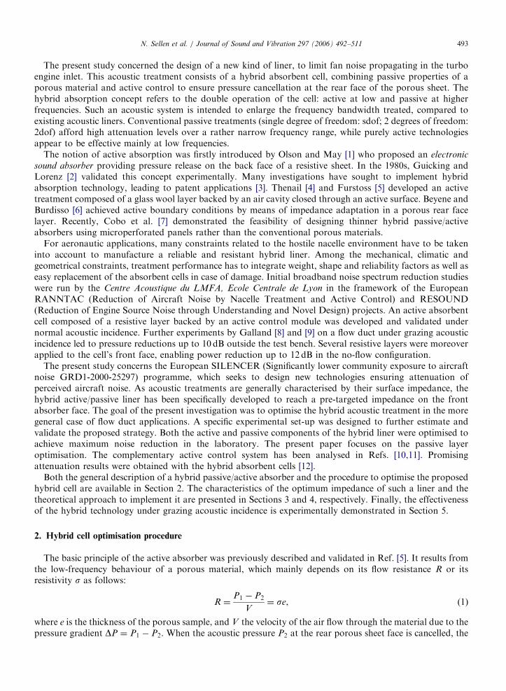
Both acoustic pressure and velocity fields were determined in a 3D ðx; y; zÞ duct characterised by twotransverse dimensions, Lx ¼ Ly ¼ 0:066m, and one longitudinal value, Lz ¼ 3:20m. Fig. 5 illustrates thecalculation set-up in the uniform mean flow case. The simulated duct was divided into three zones with diverseboundary conditions along their walls.
The first, Zone I, corresponded to the primary acoustic source region. The duct walls were entirely rigid.The second, Zone II, was the treated region, of variable length. The liner, characterised by its finite impedanceZ, could be applied to either the upper wall (y ¼ Ly=2) or both opposite duct walls (y ¼ �Ly=2 and y ¼ Ly=2).The third, Zone III, corresponded to the anechoic termination downstream of the acoustic treatment. Theduct walls were rigid.
The acoustic source was modelled as a velocity piston located at the inlet transverse plane (z ¼ 0). Althoughin the experimental set-up the primary source was situated on the upper wall, the simulation remained close tothe measurement configuration, as it was assumed that the plane wave was fully established at this location.The no flow case was completely solved for plane waves (frequency below 2.5 kHz) and high-order modes andthe acoustic field convergence verified. For instance, a parametric study showed that 10 modes were sufficient
V0=1
Mean flow U
non reflectiveboundarycondition
K II,+
U U
zK II,+
z K III,+
K I,−
z
z K II,−z
I II III
Fig. 5. Calculation configuration.

ARTICLE IN PRESSN. Sellen et al. / Journal of Sound and Vibration 297 (2006) 492–511 497
to accurately approximate the acoustic propagation inside the duct up to 5 kHz. Concerning the uniformmean-flow configuration, simulations were carried out assuming only the plane mode propagating insideMATISSE duct. The time dependance eiot is assumed.
In each of these zones, the acoustic potential Fiðx; y; zÞ ði ¼ I; II; IIIÞ can be expressed as follows:
Fiðx; y; zÞ ¼X
m
Xn
Fimnðx; yÞ½A
imne�jki;þ
z;mnz þ Bimne
jki;�z;mnz�. (3)
The indices m and n are the mth x-transverse mode, which is analytically expressed, and nth y-transversemode, which has to be numerically determined in the general case. The y-dependent contributions of theeigenfunctions Fi
mn are deduced from the transverse Helmholtz equation (4), taking into account theassociated boundary condition on the duct walls.
d2cII
dy2þ ðkII
y Þ2cII¼ 0;
dcII
dy y¼�Ly2
��� ¼ 0;
dcII
dy y¼þLy2
��� ¼ �jor0
Z1�
kIIz M
k0
� �2
cIIy¼þ
Ly2
��� ;
8>>>>>>>>><>>>>>>>>>:
(4)
where r0 is the air density, C0 the sound speed and k0 ¼ o=C0 the wavenumber. This system (4) referred to auniform impedance boundary condition over the upper duct wall. kII
z represented the axial wavenumber insidethe treated region of the duct (Fig. 5). This unknown did not appear in the boundary equation for the no-flowcase and the system was solved by a finite difference discretisation. The axial wavenumbers ki;�
z;mn in Zone IIcould then be deduced from the dispersion equation. In the presence of flow, the impedance boundarycondition required the knowledge of these axial wavenumbers and different strategies were proposed toovercome this problem, for instance by using an iterative process, or by re-writing a complete system tointroduce the axial wavenumbers as additional unknowns. As our main objective was to model the MATISSEtest bench which is devoted to plane waves and low Mach numbers (below 0.15), we decided to use thefollowing simplified formulations (5) for the axial wavenumbers in the boundary condition equation of thetreated region:
kII�z ¼
k0
1�M, (5)
where M is the Mach number.This approximation led to the following simplified boundary condition (6), which allowed to solve the same
type of system as in the no-flow case and was sufficient to provide the flow influence on the optimal impedancein a first estimation.
dcII
dy y¼þLy2
��� ¼ �jor0
Z1� 2Mð ÞcII
y¼þLy2
��� . (6)
Then, the modal amplitudes Aimn and Bi
mn were resolved with the impedance transport from the anechoictermination to the source plane, according to the generalised matrix model proposed by Roure [23].Continuity of both potential and its axial derivative were assumed between the different zones. These relationswere expressed through transformation matrices whose terms were the projections of eigenfunctions of onezone along the eigenfunctions of the next zone. It can be noticed that amplitudes Bi
mn in zone III were zero dueto the non-reflective boundary condition on the duct outlet plane. Both pressure and velocity fields can bededuced from relations (7) and (8):
piðx; y; zÞ ¼ jor0Fiðx; y; zÞ, (7)
viz ¼
qFiðx; y; zÞ
qz¼ Fi
zðx; y; zÞ. (8)

ARTICLE IN PRESSN. Sellen et al. / Journal of Sound and Vibration 297 (2006) 492–511498
The transmission loss is defined as the difference between the incident power level in Zone I and the radiatedpower level in Zone III. These values were obtained from the resulting values of the modal amplitudes forthe (0,0) mode.
3.2. Optimum impedance analysis
The optimum resistance and the optimum reactance of the liner correspond to the real and imaginary partsof Z, respectively, leading to maximum transmission-loss values.
First a 160-mm-long treated region on the upper wall of MATISSE duct was tested. The optimumimpedance for various mean-flow velocities is presented in Fig. 6. Results obviously depend on the step in thereal and imaginary parts of impedance and successive refinements down to a step of 0.01 led to the presentcurves. Optimum resistance appeared to increase with frequency, while reactance was negative and decreasedover the entire frequency range of interest. Moreover, both values were of the same order, as expected fromCremer’s results [15]. The presence of a uniform mean flow inside the duct did not significantly modify eitheroptimum resistance or reactance. Their evolution and values in the frequency range of interest remainedsimilar.
Complementary studies were performed to evaluate the influence of treatment length on optimumimpedance. Increasing the liner surface led to curves in agreement with those of Cremer and Tester (Fig. 7).Simulations showed that optimum resistance increased with the length of the treated surface, while optimumreactance was not significantly affected. The longer the liner, however, the higher the optimum attenuationlevels. Applying the finite impedance condition to two opposite walls of the MATISSE flow duct, optimumimpedance trend was not modified. Both absolute values (resistance and reactance), however, appeared abouthalf those in the reference configuration (same total length but only one treated wall).
3.3. Attenuation sensitivity study
The sensitivity of the transmission loss factor to resistance and reactance variations was analysed in order tocharacterise the optimum attenuation area, and potentially define a tolerance range for the reproduction stage
800 1000 1200 1400 1600 1800 2000 2200 24000
0.2
0.4
0.6
0.8
1
Frequency (Hz)
Re(
Z/Z
0)
800 1000 1200 1400 1600 1800 2000 2200 2400
0
−0.5
−1
−1.5
Frequency (Hz)
Im(Z
/Z0)
Fig. 6. Influence of the flow velocity on the optimum impedance: no flow (&), mean flow 20m/s (n), mean flow 50m/s (,).

ARTICLE IN PRESS
800 1000 1200 1400 1600 1800 2000 2200 24000
0.2
0.4
0.6
0.8
1
Frequency (Hz)
Re(
Z/Z
0)
800 1000 1200 1400 1600 1800 2000 2200 2400
Frequency (Hz)
Im(Z
/Z0)
0
−0.5
−1
−1.5
Fig. 7. Comparison between multimodal results (}) and Cremer’s simulation (—) in the no-flow case, comparison between multimodal
results (&) and Tester’s simulation (- - -) in the case of a mean flow of 20m/s.
N. Sellen et al. / Journal of Sound and Vibration 297 (2006) 492–511 499
of the target impedance. Fig. 8 represents the transmission loss index plotted in the impedance plane for theno-flow configuration and for various frequencies. The calculation step for the resistance and reactance wasset at 0:1Z0 in this global analysis and for this reason, small discrepancies could sometimes be found with theoptimal values of impedance obtained in the previous section. The optimum attenuation areas, defined as theimpedance plane region corresponding to maximum value minus 15 dB, appeared quite small. Their widthsreached about 0:2Z0 on both axes. Experimental work by Wirt [24] showed attenuation maps leading tosimilar conclusions: particularly narrow and quasi-circular optimum noise reduction regions. The samemaps were plotted for a mean flow velocity of 50m/s (see Fig. 9). The optimum attenuation areas weresmaller in this case. Moreover, more than one optimum area may appear at certain frequencies and flowvelocities. This phenomenon is due to the simulation configuration, where a finite (and relatively small)absorbing length is considered. This effect disappears if a finite impedance boundary condition is implementedon the entire upper wall. Therefore, the possible existence of several maximum attenuation areas must berelated to the discontinuities introduced at the boundaries between regions due to the finite length of theacoustic treatment.
3.4. Conclusion
Although the optimum impedance values must be calculated for each specific set-up, some general remarkscan be derived from the present analysis. It has been demonstrated that both the optimum resistance andreactance depend on several parameters, such as treatment area length and the number of walls covered by thefinite impedance condition. Furthermore, higher flow velocities may affect these values. The evolution of thesimulated optimum impedance with frequency is in agreement with previous findings by Cremer and Tester.Since both optimum resistance and reactance do not significantly depend on flow for the low velocitiesconsidered in the present study, it can be assumed that the optimum impedance obtained in the no-flow case isthe target impedance to be achieved at the liner input. However, this value must be precisely reproduced toreach high attenuation levels, especially in the presence of flow.

ARTICLE IN PRESS
0.2 0.4 0.6 0.8 1 1.2−1.5
−1
−0.5
0
(a) : 800 Hz0
10
20
30
40
0.2 0.4 0.6 0.8 1 1.2−1.5
−1
−0.5
0
(b) : 1000 Hz0
10
20
30
40
0.2 0.4 0.6 0.8 1 1.2−1.5
−1
−0.5
0
Re(Z /Z0)
Re(Z /Z0) Re(Z /Z0)
Im(Z
/Z0)
Im(Z
/Z0)
Im(Z
/Z0)
Im(Z
/Z0)
Im(Z
/Z0)
Im(Z
/Z0)
(c) : 1250 Hz0
10
20
30
40
0.2 0.4 0.6 0.8 1 1.2−1.5
−1
−0.5
0
Re(Z /Z0)
(d) : 1600 Hz0
10
20
30
40
0.2 0.4 0.6 0.8 1 1.2−1.5
−1
−0.5
0
Re(Z /Z0)
(e) : 2000 Hz0
10
20
30
40
0.2 0.4 0.6 0.8 1 1.2−1.5
−1
−0.5
0
Re(Z /Z0)
(f) : 2500 Hz0
10
20
30
40
Fig. 8. Sensitivity study: transmission loss predicted in the impedance plane, for different frequencies. No-flow case. (a) 800Hz, (b)
1000Hz, (c) 1250Hz, (d) 1600Hz, (e) 2000Hz, (f) 2500Hz.
N. Sellen et al. / Journal of Sound and Vibration 297 (2006) 492–511500
4. Selection of the passive layer
The goal of this optimisation stage was to determine the parameters of the porous layer under a rear faceboundary condition, leading to the desired surface impedance values. First studies dealing with the selection ofa suitable active/passive liner only concerned a precise achievement of the target surface resistance [8].However, the conclusions of the previous section suggest a non-negligible influence of the optimum reactance,especially in the highest frequency range where quite strongly negative values were reached. Simultaneousachievement of optimum resistance and reactance values is currently being investigated.
The acoustic behaviour of a porous layer has been described by five characteristic parameters as resistivity,porosity, tortuosity and two characteristic lengths (or respective viscous and thermal shape factors, s and s0) inthe model proposed by Allard [25]. Two additional parameters, the thickness e of the passive layer, and thedepth d of the air gap behind the porous sheet, are needed to model the input impedance of the porous sheet,for hybrid liner functioning (see Fig. 2). Considering the large number of parameters involved, the complexityof the function to be minimised and the difficulty of finally finding a material having the target characteristicparameters, we adopted a step-by-step selection process among existing absorbent materials. According toprevious analyses, a constant target resistance can be precisely reproduced throughout a large frequency rangefor thin and highly resistive materials [9] in the active mode. Under these conditions, reactance was very closeto zero, and often slightly positive. On the contrary, material thickness should be increased and resistivityreduced to reach a negative decreasing reactance. However, this behaviour afforded higher resistance valuesthan those expected. In order to establish the best compromise to reach the desired impedance values, some

ARTICLE IN PRESS
0.2 0.4 0.6 0.8 1 1.2
0
(a): 800 Hz0
10
20
30
40
0.2 0.4 0.6 0.8 1 1.2
0
Im(Z
/Z0)
(b) : 1000 Hz0
10
20
30
40
0.2 0.4 0.6 0.8 1 1.2
0
Im(Z
/Z0)
(c): 1250 Hz0
10
20
30
40
0.2 0.4 0.6 0.8 1 1.2
0
Im(Z
/Z0)
(d) : 1600 Hz0
10
20
30
40
0.2 0.4 0.6 0.8 1 1.2
0
Im(Z
/Z0)
(e): 2000 Hz0
10
20
30
40
0.2 0.4 0.6 0.8 1 1.2
0Im
(Z/Z
0)
(f) : 2500 Hz0
10
20
30
40
Im(Z
/Z0)
Re(Z / Z0) Re(Z / Z0)
Re(Z / Z0) Re(Z / Z0)
Re(Z / Z0) Re(Z / Z0)
Fig. 9. Sensitivity study: transmission loss predicted in the impedance plane, for different frequencies. Uniform flow 50m/s. (a) 800Hz,
(b) 1000Hz, (c) 1250Hz, (d) 1600Hz, (e) 2000Hz, (f) 2500 Hz.
N. Sellen et al. / Journal of Sound and Vibration 297 (2006) 492–511 501
common porous materials in a single or multilayer set-up, with different rear boundary conditions, weresuccessively studied.
The porous media considered in this section had been previously characterised by an inverse acousticmethod using standing wave-tube measurements [26]. First, some wire meshes were tested. Such materials arecommonly used in turbo-engine nacelle applications. On account of their particular properties (extremely thinand highly resistive layers), these materials show broadband acoustic behaviour. When associated to specificoperating conditions, this sort of layer leads to strong noise reduction. When a pressure release condition isachieved on the rear face of a highly resistive material such as a wire mesh, its surface resistance comes toapproximately equal its flow resistance R ¼ se. Therefore, an appropriate choice of the product se enablesquite precise reproduction of the target resistance, because the optimum value does not significantly changeover the frequency range of interest, as shown in Fig. 6. For the specific MATISSE set-up, a wire meshmanufactured by GANTOIS, with a resistance close to 0:3Z0, was selected. However, the related surfacereactance appeared slightly positive, whereas the target frequency shape should be negatively decreasing. Wiremesh materials in the active mode were thus not suited to simultaneously achieving both optimum resistanceand reactance curves.
Using a single porous layer in active mode was then tested. The modelling of porous media revealed thatnegative reactance could be achieved but only for materials having a resistance significantly greater than thetarget value. For instance, Fig. 10 reports the surface impedance of 9-mm-thick rock wool (resistivitys ¼ 1:37105 rayls=m), backed by a pressure release condition. Such a configuration provided the negativedecreasing optimum reactance, but its resistance was rather high (3Z0) compared to the desired mean value(about 0:5Z0).

ARTICLE IN PRESS
800 1000 1200 1400 1600 1800 2000 2200 2400−1
0
1
2
3
4
5
Frequency (Hz)
Re(
Z/Z
0)
800 1000 1200 1400 1600 1800 2000 2200 2400−3
−2
−1
0
1
Frequency (Hz)
Im(Z
/Z0)
Fig. 10. Surface impedance predictions in active mode: comparison between the optimum impedance for the MATISSE flow duct (&), the
wire mesh surface impedance (—), the 9-mm-thick rock wool surface impedance (- - -) and the multilayer wire mesh and 4mm thick-rock
wool surface impedance (— —).
N. Sellen et al. / Journal of Sound and Vibration 297 (2006) 492–511502
Another study concerned a multilayer configuration. The passive sheet at the input of the hybrid absorberwas composed of the wire mesh, a 17-mm-deep air gap and a 4-mm-thick rock wool sample. The wire meshenabled cell surface resistance to be controlled, while the air gap and rock wool couple provided the desirednegative reactance frequency shape. Fig. 10 shows the surface impedance of this multilayer under a pressurerelease condition. These results represent a fairly accurate reproduction of the imaginary negative decreasingpart. However, the real impedance part still remains high (� 1:7Z0) as compared to the optimum value,although lower than with the single rock wool layer. Indeed, a low-frequency approximation of the inputimpedance of such an assemblage is given by
Z
Z0¼ R1 þ R2 þ j tanðk0dÞð1� R2
2Þ, (9)
where R1 and R2 are the specific resistances of the front and back layers, and d the air gap length.Consequently, a negative reactance is obtained for R2 greater than one, leading to an overly high globalresistance.
The passive functioning of the liner was also studied, in order to approximate optimum impedance in thehigher frequency range. Surface impedance was predicted for each of the previous porous media backed by a20-mm-deep air cavity. The results are presented in Fig. 11. The air gap slightly modified the surface resistanceof these materials and introduced strongly negative reactance values in the low frequency range. However, athigher frequencies, the imaginary part increased and the surface impedance became similar to the targetvalues.
This theoretical study highlighted the difficulty of simultaneously reproducing both optimum values in thecase of the MATISSE flow duct. Thus a compromise between reliable resistance and precise reactance wasrequired so as to be able to select the best-suited passive layer for the hybrid absorber. The new materialselection criterion was the sound attenuation achieved.
The simulated transmission loss of the wire mesh and the multilayer configuration, both backed by an activeboundary condition (pressure release), are reported in Fig. 12. In the low frequency range, below 1.6 kHz, the

ARTICLE IN PRESS
800 1000 1200 1400 1600 1800 2000 2200 2400
0
1
2
3
4
5
Frequency (Hz)
Re(
Z/Z
0)
800 1000 1200 1400 1600 1800 2000 2200 2400
0
1
Frequency (Hz)
Im(Z
/Z0)
Fig. 11. Surface impedance predictions in passive mode (0.02m deep back cavity): comparison between the optimum impedance for the
MATISSE flow duct (&), the wire mesh surface impedance (—), the 9-mm-thick rock wool surface impedance (- - -) and the multilayer
wire mesh and 4-mm-thick rock wool surface impedance (— —).
Fig. 12. Transmission loss simulations for acoustic treatments placed on MATISSE upper wall over 160mm: calculations using surface
impedance predictions with a pressure cancellation rear face boundary condition. Wire mesh (—), multilayer composed of the wire mesh
and the 4-mm-thick rock wool (- - -).
N. Sellen et al. / Journal of Sound and Vibration 297 (2006) 492–511 503
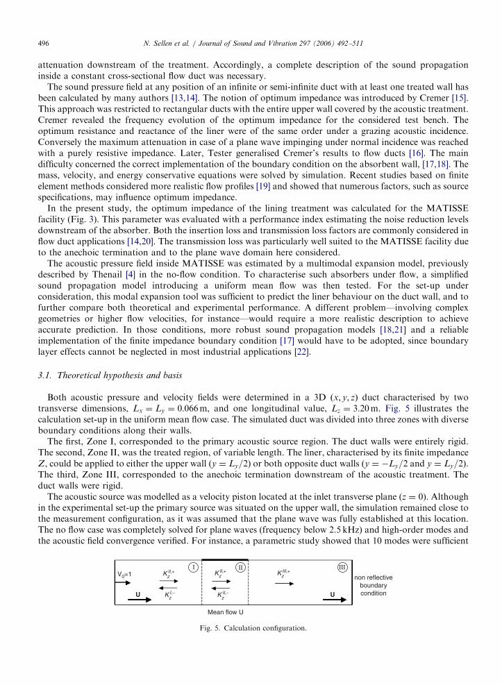
selected wire mesh seemed to be the most effective solution, giving greater attenuation. Achieving targetresistance was a critical factor for low frequencies, provided that reactance remained weak. Nevertheless, asfrequency increased, the performance of the wire mesh sheet decreased sharply and the noise reduction withthe multilayer configuration became more significant. Fig. 13 compares the transmission loss obtained withthe same wire mesh for the active mode and for three passive boundary conditions (10–15 and 20-mm-deep aircavities). These curves reveal the benefit of combining passive and active techniques to improve noise
ARTICLE IN PRESS
Fig. 13. Transmission loss simulations for the wire mesh placed on MATISSE upper wall over 160mm: comparison between the active
mode (—) and three passive rear face boundary conditions: a 10mm deep air cavity (— —), a 15-mm-deep air cavity (– - –) and a 20-mm-
deep air cavity (- - -).
Fig. 14. Transmission loss simulations for the wire mesh placed on MATISSE upper wall (—) and split on both opposite walls (- - -).
Active mode.
N. Sellen et al. / Journal of Sound and Vibration 297 (2006) 492–511504
reduction over a wider frequency range. In this high frequency range, achieving optimum reactance appears tobe the critical factor. A cut-off frequency between active and passive functioning modes can be determined foreach particular set-up (material properties and air cavity depth). With the 20-mm-thick air gap, for instance,the shift from active to passive mode is at 1.8 kHz. Greater attenuation levels can be obtained covering longersurfaces on the upper wall or, as shown in Fig. 14, with the same total area on both opposite walls, althoughthe complete optimisation procedure was not replicated for these configurations.
5. Experimental validation
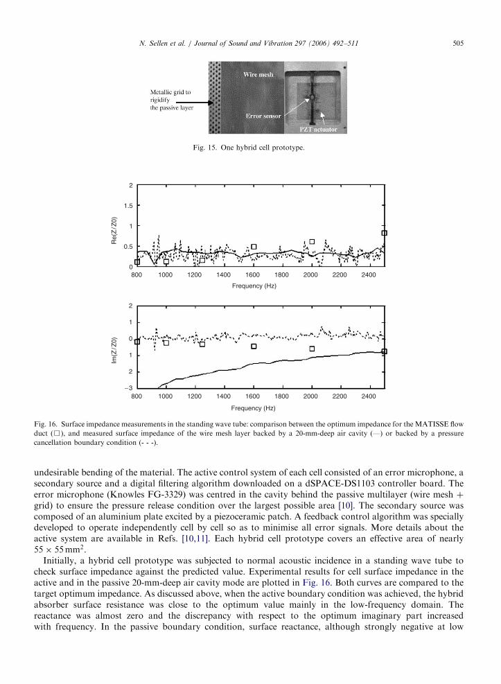
The theoretical results from previous sections were experimentally verified. Four prototype hybrid cells(Fig. 15) were manufactured by METRAVIB to be tested on the MATISSE flow duct under grazing acousticincidence. Each hybrid absorbent cell was composed of a passive layer and an active control system. Thepassive layer on the front face of the cell was the selected wire mesh backed by a metallic grid to avoid any
ARTICLE IN PRESS
Fig. 15. One hybrid cell prototype.
2
1.5
1
0.5
0
2
1
0
1
2
−3
800 1000 1200 1400 1600
Frequency (Hz)
Re(
Z/Z
0)Im
(Z/Z
0)
1800 2000 2200 2400
800 1000 1200 1400 1600
Frequency (Hz)
1800 2000 2200 2400
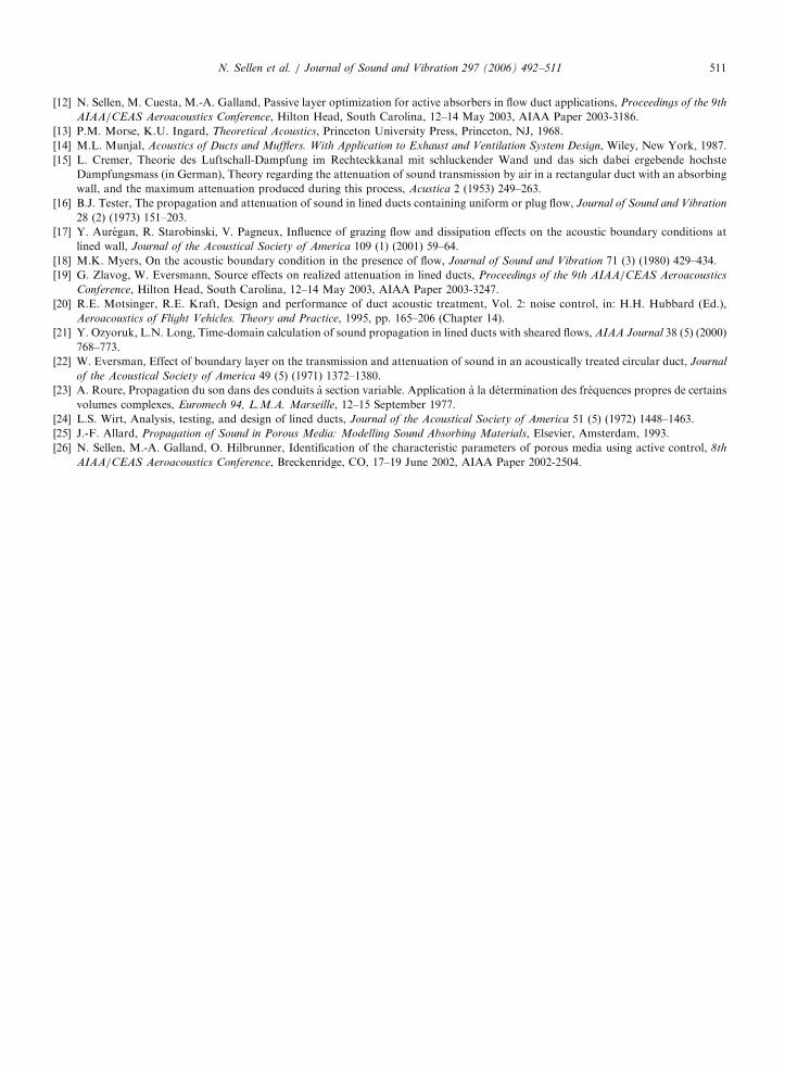
Fig. 16. Surface impedance measurements in the standing wave tube: comparison between the optimum impedance for the MATISSE flow
duct (&), and measured surface impedance of the wire mesh layer backed by a 20-mm-deep air cavity (—) or backed by a pressure
cancellation boundary condition (- - -).
N. Sellen et al. / Journal of Sound and Vibration 297 (2006) 492–511 505
undesirable bending of the material. The active control system of each cell consisted of an error microphone, asecondary source and a digital filtering algorithm downloaded on a dSPACE-DS1103 controller board. Theerror microphone (Knowles FG-3329) was centred in the cavity behind the passive multilayer (wire mesh þgrid) to ensure the pressure release condition over the largest possible area [10]. The secondary source wascomposed of an aluminium plate excited by a piezoceramic patch. A feedback control algorithm was speciallydeveloped to operate independently cell by cell so as to minimise all error signals. More details about theactive system are available in Refs. [10,11]. Each hybrid cell prototype covers an effective area of nearly55� 55mm2.
Initially, a hybrid cell prototype was subjected to normal acoustic incidence in a standing wave tube tocheck surface impedance against the predicted value. Experimental results for cell surface impedance in theactive and in the passive 20-mm-deep air cavity mode are plotted in Fig. 16. Both curves are compared to thetarget optimum impedance. As discussed above, when the active boundary condition was achieved, the hybridabsorber surface resistance was close to the optimum value mainly in the low-frequency domain. Thereactance was almost zero and the discrepancy with respect to the optimum imaginary part increasedwith frequency. In the passive boundary condition, surface reactance, although strongly negative at low

ARTICLE IN PRESSN. Sellen et al. / Journal of Sound and Vibration 297 (2006) 492–511506
frequencies, became almost optimal at higher frequencies. The theoretical predictions for optimum impedancewere experimentally validated.
5.1. Experimental setup
Experiments on such hybrid cells under grazing acoustic incidence were conducted in the MATISSE flowduct (Fig. 17), already described in Section 2. Two couples of B&K 1=400 microphones were flush-mountedupstream (M1,M2) and downstream (M3,M4) of the test section, to further estimate the performance indices(Fig. 3). The primary acoustic source—a loudspeaker enclosed in a wooden box filled with rock wool—waslocated in a side-branch configuration over the upper wall of the main duct. This source was driven by eitherpure tones or swept sine signals, ensuring a sufficient signal-to-noise ratio at high flow velocities. Noise levelsinside the MATISSE flow duct ranged from 110 to 120 dB. The tested flow velocities were quite low: up to50m/s ðM ¼ 0:15Þ. The frequency bandwidth of interest was reduced to the plane wave range, set from 0.7 to2.5 kHz.
The transmission loss index was estimated with a set of three flush-mounted microphones. The pressuresignals at microphones M1 and M2 were recorded to extract the incident wave component I, inside zone I ofthe duct. Due to the anechoic termination, only one signal (from M3 for example) was necessary to obtain thetransmitted wave component T . Coherence between signals was checked in all tests. Accordingly, theexperimental transmission loss value was deduced from
TL ¼ 20 logI
T
��������. (10)
Before starting the experiments, the anechoic termination of the MATISSE set-up was experimentallyconfirmed. The reflection coefficient inside the flow duct was estimated from signals picked either up atmicrophones M1/M2 or M3/M4, without any acoustic treatment. It was lower than 0.1 over the entirefrequency range, even in the most critical case (for flow velocity 50m/s).
Several configurations were tested on the upper wall of the duct in order to validate the general concept ofhybrid absorption. Note that only results concerning the selected wire mesh sheet are presented here. Both thepassive and active functioning modes of the four hybrid cell prototypes were checked for an acoustic treatmentof the same size ðeffective length ¼ 220mmÞ.
5.2. Measurements in the passive mode
The first result involved the passive behaviour of a conventional treatment (sdof liner). In this casethe wire mesh was backed by a 17mm deep honeycomb having 9mm wide cells. A swept sine signal
Fig. 17. MATISSE experimental facility.

ARTICLE IN PRESSN. Sellen et al. / Journal of Sound and Vibration 297 (2006) 492–511 507
from 0.7 to 2.5 kHz with a step of 0.2 kHz was used. Fig. 18 shows the transmission loss obtained fordifferent flow velocities. As expected, the attenuation is very poor at low frequencies but stronglyincreasing with the frequency. The liner performance at higher frequencies seems to be slightly superior in thepresence of flow.
The next experiment was devoted to testing the performance of the hybrid cells in the passive mode, with a20-mm-deep air gap. Transmission losses for the various flow velocities are plotted in Fig. 19. Once more, thepassive behaviour was confirmed. As expected, higher attenuation levels were reached, since the air cavity wasgreater. The flow effect remained negligible. The greatest sound reduction was obtained at 2.3 kHz, where theimpedance achieved by the treatment is very close to target for both the real and imaginary parts, as can beseen on Fig. 16.
In conclusion, the passive behaviour of the prototype was in agreement with predictions. Moreover, thehypothesis underlying the calculations, i.e., that the absorber behaves as a locally reacting material, wasconfirmed.
Fig. 18. Transmission loss for the passive sdof treatment at different flow velocities. No flow (—), flow 5m/s (— —), flow 10m/s (- - -),
flow 20m=s ðþÞ, flow 30m=s ð�Þ, flow 40m=s ð�Þ, flow 50m/s (&).
Fig. 19. Transmission loss measurements for the passive functioning mode of the hybrid cells, for different flow velocities until up to 50m/s.
No flow (—), flow 5m/s (— —), flow 10m/s (- - -), flow 20m=s ðþÞ, flow 30m=s ð�Þ, flow 40m=s ð�Þ, flow 50m/s (&).

ARTICLE IN PRESSN. Sellen et al. / Journal of Sound and Vibration 297 (2006) 492–511508
5.3. Measurements in the active mode
The frequency range to test the active functioning mode of the hybrid absorber was set from 0.7 to 1.9 kHz.As discussed in the theoretical study, above this upper frequency the passive solutions become more effective.Fig. 20 represents the measured transmission losses obtained for flow velocities between 0 and 50m/s, whenthe active control system on the rear porous layer face is turned on. As expected, considerable noise reductionwas obtained at low frequencies (from 20 to 25 dB at 0.7 kHz), whereas the attenuation sharply decreased asfrequency increased. The presence of flow did not significantly modify the experimental transmission loss,except from the lower frequency range where it was reduced as flow velocity increased. The experimentalresults were in agreement with the predicted curves. The outcome of reducing the treated area (using only twoactive cells) is shown in Fig. 21: the longer the treated surface, the greater the attenuation, as predictedtheoretically.
Fig. 20. Transmission loss measurements for the active functioning mode for different flow velocities: No flow (—), flow 5m/s (— —),
flow 10m/s (- - -), flow 20m=s ðþÞ, flow 30m=s ð�Þ, flow 40m=s ð�Þ, flow 50m/s (&).
Fig. 21. Transmission loss measurements for the active functioning mode for different treated surfaces: 4 active cells (—) and 2 active cells
(- - -), flow velocity 50m/s.

ARTICLE IN PRESSN. Sellen et al. / Journal of Sound and Vibration 297 (2006) 492–511 509
5.4. Hybrid absorption
Finally, the hybrid functioning of the absorbent prototype was considered. Figs. 22 and 23 superimpose themeasured and predicted transmission-loss parameters in both active and passive functioning modes in the no-flow configuration and for a mean flow velocity of 50m/s, respectively. The experimental results agreed withthe predictions, with an effective length of 190mm for the treatment, instead of the real value of 220mm.A possible reason is that the pressure reduction was not uniform at the rear face of the wire mesh. Indeed,pressure was minimised at the site of the error microphone, in the centre of each cell. However, measurementshowed that, under grazing incidence, the effectiveness of control was significantly reduced at the cell edges.Another possible reason is that reflections encountered with a liner having splices like the hybrid treatmentlead to reduced effectiveness. In fact, all the differences from an ideal uniform impedance boundary conditionwere taken into account by reducing the treated area by a ratio of 0.86. According to the theoretical study, theexperimental cut-off frequency could be set at 1.8 kHz in the no-flow condition, and was not greatly modifiedfor higher flow velocities. Both graphs validate the hybrid absorption concept, since significant attenuation
Fig. 22. Comparison between transmission loss predictions and measurements for the hybrid functioning of the cells (no-flow condition):
active mode simulation (- - -), active mode measurement (&), passive mode simulation (—), passive mode measurement ð�Þ.
Fig. 23. Comparison between transmission loss predictions and measurements for the hybrid functioning of the cells (flow 50m/s): active
mode simulation (- - -), active mode measurement (&), passive mode simulation (—), passive mode measurement ð�Þ.

ARTICLE IN PRESSN. Sellen et al. / Journal of Sound and Vibration 297 (2006) 492–511510
levels were achieved throughout the frequency bandwidth: up 25 dB at 0.7 kHz for the active boundarycondition and up to 18 dB at 2.4 kHz for the passive boundary condition.
6. Conclusions
A hybrid active/passive treatment was designed to provide broadband noise reduction in flow ductapplications. A general procedure to optimise the absorbent cell in a specific laboratory facility was developed.A highly resistive sheet composed of a wire mesh with a resistance close to a third of characteristic airimpedance was found to be the most suitable passive layer configuration for any flow velocity up to 50m/s.The optimum cut-off frequency between the active and the passive functioning mode was determined as1.8 kHz. The hybrid absorption concept was completely validated, both theoretically and experimentally, sincesignificant sound attenuation was obtained in both the low (up to 25 dB at 0.7 kHz) and high frequency range(up to 20 dB at 2.4 kHz). Attenuation fell to 6 dB in the middle frequency range because the selectedconfiguration resulted from a compromise over the whole frequency range. A sensitivity study showed that theoptimum impedance must precisely be reproduced to reach high attenuation levels. Consequently, future workwill focus on implementing liners of variable and frequency-dependent impedance, combining active andpassive means. A multilayer prototype with an error sensor in the air space between the two porous layersappears suitable for approaching both optimum resistance and reactance curves. The liner optimisationprocedure proposed and carried out in this paper could be applied to any more complex test-bench orindustrial application. However, the characteristics of each new set-up should be taken account of incalculating the optimum impedance. Moreover, more robust and realistic models should be implemented forcomplex flow profiles and higher propagation modes. The hybrid liner concept could also be applied in otherhostile environments, such as hot streams, by selecting a resistive acoustic layer also integrating thermalisolation properties. Likewise, the porous layer could, in addition to the passive absorption, provide a meansof protection against shock and air or liquid flow for the active system.
Acknowledgements
This research was supported by the European Community, under the Silence(r) project (GRD1-2000-25297). The authors acknowledge Fundacion la Caixa and the French Government for funding the post-doctoral fellowship of Maria Cuesta at the Centre Acoustique du LMFA (Ecole Centrale de Lyon).
References
[1] H.F. Olson, E.G. May, Electronic sound absorber, Journal of the Acoustical Society of America 25 (1953) 1130–1136.
[2] D. Guicking, E. Lorenz, An active sound absorber with porous plate, Journal of Vibration and Acoustics 106 (1984) 389–392.
[3] F.P. Mechel, Hybrider Schalldamplfer, Patent No DE4027511.
[4] D. Thenail, Controle actif d’impedance et optimisation des performances d’un materiau poreux, PhD Thesis, Ecole Centrale de Lyon,
Ecully, France, 1995.
[5] M. Furstoss, D. Thenail, M.A. Galland, Surface impedance control for sound absorption: direct and hybrid passive/active strategies,
Journal of Sound and Vibration 203 (2) (1997) 219–236.
[6] S. Beyene, A. Burdisso, A new passive/active noise absorption system, Journal of the Acoustical Society of America 101 (3) (1997)
1512–1515.
[7] P. Cobo, J. Pfretzschner, M. Cuesta, D.K. Anthony, Hybrid passive–active absorption using microperforated panels, Journal of the
Acoustical Society of America 116 (4) (2004) 2118–2125.
[8] M.-A. Galland, P. Souchotte, P. Ladner, T. Mazoyer, Experimental investigation of noise reduction in a flow duct through hybrid
passive/active liner, Proceedings of the 7th AIAA/CEAS Aeroacoustics Conference, Maastricht, The Netherlands, 28–30 May 2001,
AIAA Paper 2001-2221.
[9] M.-A. Galland, N. Sellen, O. Hilbrunner, Noise reduction in a flow duct by active control of wall impedance, Proceedings of the 8th
AIAA/CEAS Aeroacoustics Conference, Breckenridge, Colorado, 17–19 June 2002, AIAA Paper 2002-2213.
[10] O. Hilbrunner, M.A. Galland, N. Sellen, J. Perisse, Optimisation of a hybrid acoustic liner for noise reduction of engine aircraft
nacelles, Proceedings of ACTIVE 2002—The 2002 International Symposium on Active Control of Sound and Vibration, Vol. 1,
Southampton, UK, 2002, pp. 657–668.
[11] B. Mazeaud, N. Sellen, M.A. Galland, Design of an adaptive hybrid liner for flow duct applications, Proceedings of the 10th AIAA/
CEAS Aeroacoustics Conference, Manchester, UK, 10–12 May 2004, AIAA Paper 2004-2852.
ARTICLE IN PRESSN. Sellen et al. / Journal of Sound and Vibration 297 (2006) 492–511 511
[12] N. Sellen, M. Cuesta, M.-A. Galland, Passive layer optimization for active absorbers in flow duct applications, Proceedings of the 9th
AIAA/CEAS Aeroacoustics Conference, Hilton Head, South Carolina, 12–14 May 2003, AIAA Paper 2003-3186.
[13] P.M. Morse, K.U. Ingard, Theoretical Acoustics, Princeton University Press, Princeton, NJ, 1968.
[14] M.L. Munjal, Acoustics of Ducts and Mufflers. With Application to Exhaust and Ventilation System Design, Wiley, New York, 1987.
[15] L. Cremer, Theorie des Luftschall-Dampfung im Rechteckkanal mit schluckender Wand und das sich dabei ergebende hochste
Dampfungsmass (in German), Theory regarding the attenuation of sound transmission by air in a rectangular duct with an absorbing
wall, and the maximum attenuation produced during this process, Acustica 2 (1953) 249–263.
[16] B.J. Tester, The propagation and attenuation of sound in lined ducts containing uniform or plug flow, Journal of Sound and Vibration
28 (2) (1973) 151–203.
[17] Y. Auregan, R. Starobinski, V. Pagneux, Influence of grazing flow and dissipation effects on the acoustic boundary conditions at
lined wall, Journal of the Acoustical Society of America 109 (1) (2001) 59–64.
[18] M.K. Myers, On the acoustic boundary condition in the presence of flow, Journal of Sound and Vibration 71 (3) (1980) 429–434.
[19] G. Zlavog, W. Eversmann, Source effects on realized attenuation in lined ducts, Proceedings of the 9th AIAA/CEAS Aeroacoustics
Conference, Hilton Head, South Carolina, 12–14 May 2003, AIAA Paper 2003-3247.
[20] R.E. Motsinger, R.E. Kraft, Design and performance of duct acoustic treatment, Vol. 2: noise control, in: H.H. Hubbard (Ed.),
Aeroacoustics of Flight Vehicles. Theory and Practice, 1995, pp. 165–206 (Chapter 14).
[21] Y. Ozyoruk, L.N. Long, Time-domain calculation of sound propagation in lined ducts with sheared flows, AIAA Journal 38 (5) (2000)
768–773.
[22] W. Eversman, Effect of boundary layer on the transmission and attenuation of sound in an acoustically treated circular duct, Journal
of the Acoustical Society of America 49 (5) (1971) 1372–1380.
[23] A. Roure, Propagation du son dans des conduits a section variable. Application a la determination des frequences propres de certains
volumes complexes, Euromech 94, L.M.A. Marseille, 12–15 September 1977.
[24] L.S. Wirt, Analysis, testing, and design of lined ducts, Journal of the Acoustical Society of America 51 (5) (1972) 1448–1463.
[25] J.-F. Allard, Propagation of Sound in Porous Media: Modelling Sound Absorbing Materials, Elsevier, Amsterdam, 1993.
[26] N. Sellen, M.-A. Galland, O. Hilbrunner, Identification of the characteristic parameters of porous media using active control, 8th
AIAA/CEAS Aeroacoustics Conference, Breckenridge, CO, 17–19 June 2002, AIAA Paper 2002-2504.