Embed Size (px)
Citation preview

Noise Control in BuildingsGuidelines for Acoustical Problem-Solving
The technology of noise controlboth inside and outside buildings
is well developed today.The problem is that
it is too seldom used.Robert B. Newman, Architect
”
“

I IntroductionThe problem of noise in the built environment ................................................................................ 2There are solutions ......................................................................................................................... 2CertainTeed Corporation and its acoustical products ...................................................................... 2Some historical milestones ............................................................................................................. 3
II Fundamentals of acousticsProperties of sound: frequency, wavelength, amplitude .......................................................... 4, 5How we measure sound; how we hear sound ............................................................................. 6Other sound properties: duration, propagation ........................................................................ 6, 7How much sound is acceptable? Noise criteria (NC) values ......................................................... 7Sound paths, airborne and structureborne .................................................................................... 8
III Airborne sound transmissionSound transmission loss, sound transmission class (STC) .............................................................. 9Lightweight double-leaf walls .................................................................................................. 9, 10Insulation density and STC........................................................................................................... 11Sound transmission loss and noise control ................................................................................. 11Sound flanking paths ................................................................................................................... 11
IV Structureborne sound transmissionFloor impact insulation class (IIC) ................................................................................................. 12
V Sound absorptionDefinition; measurement of sound absorption ............................................................................. 13Properties of sound absorbers ...................................................................................................... 13Sound absorption and noise control ............................................................................................. 14Sound level reduction calculation ................................................................................................. 15Reverberation time calculation ...................................................................................................... 15
VI Principles of SPR noise controlControlling noise at the source ..................................................................................................... 16Controlling noise along its path .................................................................................................... 16Controlling noise at the receiver ................................................................................................... 16Temporary sound control .............................................................................................................. 17Three steps to noise control solutions .......................................................................................... 17
VII HVAC noise controlFiber glass duct liner ..................................................................................................................... 18Fiber glass duct board .................................................................................................................. 18
VIII Five noise control mistakes to avoid .......................................................................................... 19IX Tables of sound absorption and sound transmission loss properties
Sound absorption coefficients, typical building materials ............................................................. 20Sound absorption coefficients, CertainTeed fiber glass insulations .............................................. 21Sound transmission loss values, typical building materials ........................................................... 22Sound transmission loss values, wood stud wall assemblies ................................................. 23, 24Sound transmission loss values, steel stud wall assemblies ............................................ 25, 26, 27
X AppendixAcoustical guide specification ...................................................................................................... 28Glossary of terms ................................................................................................................... 29, 30Worksheet for calculation of room reverberation level and time ................................................ 31References for further reading .................................................................................................... 31CertainTeed CertaProTM acoustical insulations ........................................................................... 32
NOTE:In preparing this manual, CertainTeed Corporation has taken care to include accurately all information relevant to basic application ofnoise control products and systems. However, because of the many variables that may arise in construction technology, the importanceof correct installation of acoustical materials, and other factors including use and occupancy, no liability can be assumed for applicationof the principles and techniques contained herein. CertainTeed Corporation makes no warranty, express or implied or regardingmerchantability or fitness for a particular purpose, in connection with the information supplied herein.
1
CONTENTS

The problem of noise in the built environment
It’s a noisy world. Twenty-four hours a day, seven days a week,we are exposed to sounds we do not want, need, or benefitfrom. There are few places on the planet where in our daily liveswe are free from unwanted sounds.
Noise from many outdoor sources assails our hearing as itinvades our homes and work places: traffic, aircraft, barkingdogs, neighbors’ voices. Noise within the workplace—fromoffice machines, telephones, ventilating systems, unwantedconversation in the next cubicle—distracts us from our workand makes us less productive.
Noise from within the home—from appliances, upstairsfootsteps, TV sound traveling from room to room—keeps ourhomes from being the restful refuges they ought to be.Noise in the classroom impedes the learning process andthreatens our children’s educational experience.
Noise can frustrate and impede speech communication. It canimperil us as we walk or drive city streets. It can be a physicalhealth hazard as well: exposure to high noise levels can causepermanent hearing loss.
In short: Noise is unwanted sound.
There are solutions
We don’t need to suffer the distracting, fatiguing, andunhealthful consequences of noise. There are practical andeconomical solutions to almost all noise problems in the builtenvironment. To approach the solution to any specific noiseproblem, we need to:
1. Understand the basic physics of acoustics and hownoise—unwanted sound—is produced, how itpropagates, and how it is controlled.
2. Learn the basics of noise control, and how to approachthe problem from three standpoints: the source of noise,the path it travels, and the point of reception.
3. Become familiar with, and discover how to apply inboth new and remodeling construction, the acousticalproducts and systems that control noise—products thatcontribute to the creation of acoustically comfortable,productive and healthful environments.
That’s what architects, engineers, contractors, and buildingowners—anyone concerned with solving noise control prob-lems in all types of buildings—will find in this manual. Itincludes information on how to solve specific noise controlproblems using CertainTeed acoustical products and systems.These products are made of the most versatile, cost-effective,safe, and easily applied sound control material yet devised:fiber glass.
Who is CertainTeed?
CertainTeed Corporation is a member of the Compagniede Saint-Gobain family, a recognized global leader in highperformance building materials technology and the world’spreeminent manufacturer of fiber glass insulation products.CertainTeed’s Insulation Group manufactures and markets acomplete line of fiber glass thermal and acoustical insulationproducts which include:
CertaProTM insulation products for commercial construction.CertainTeed insulations for use in residential construction.CertainTeed HVAC products for commercial andresidential air duct systems.
The name CertainTeed means Quality Made Certain—Satisfaction GuaranTeed. We were the first fiber glassinsulation manufacturer in the United States to have itsmanufacturing plants, Research and Development Centerand corportate headquarters registered to ISO 9001-2000standards. Certification indicates third-party verification ofimplemented quality assurance practices as defined in the ISOstandard including document control, training requirements,management review, and system auditing. Product quality andconformance to specifications are continuously monitored inour Research and Development Center and in the qualitycontrol laboratories at all our manufacturing facilities.
All CertainTeed plants have achieved ISO 14001 registration inenvironmental management. And earlier this year CertainTeedhad its fiberglass insulation productscertified by the GREENGUARDEnvironmental Institute. This third-party certification attests to the lowemissions of VOCs, formaldehyde,and other particulates.
CertainTeed acoustical insulation products provide anotherimportant benefit in residential and commercial construction:energy conservation. The high thermal efficiency of our fiberglass insulation products means less energy is required toheat and cool our buildings. This reduces the amount ofgreenhouse gases from theburning of fossil fuels. AllCertainTeed insulationproducts are qualifiedto meet the EPA andDepartment of Energy“Energy Star” conservationprogram and to wearthe “Energy Star” logo.
If you need assistance in solving noise control problemsthrough application of CertainTeed acoustical products,please contact us at 1-800-233-8990. More information onCertainTeed’s building products and systems is availablethrough our Fax-On-Demand Line, 1-800-947-0057.Or check out our web site at www.certainteed.com.
I. INTRODUCTION
2

SOME HISTORICAL MILESTONES
Take a seat—any seat—in the great semicircular outdooramphitheater at Epidaurus, in Greece. Place a player at thecenter of the performance space. Listen closely: youcan almost hear a whisper from as far as two hundred feetaway. The Greeks knew enough about how sound propagatesto have achieved this astonishing acoustical success as longago as the 5th century B.C.
The Romans could design interiors with ideal acoustics.Stand against the wall in Rome’s Pantheon and your breathingcan be heard by someone standing opposite you across thegreat hemispherical space. The cathedral builders of Europe’sMiddle Ages knew how to build for maximum acoustical effect.Sir Christopher Wren and other 18th century architectsdiscovered how to design concert halls to optimize thelistening experience at any seat.
Still, little was known about the physical science andmeasurement of sound until Sir Isaac Newton. He demonstratedthat sound waves travel through any medium—solid, liquid, orgaseous—and that the speed with which they propagatedepends upon the elasticity and density of the medium.
In 1866, the fundamental nature of sound waves was vividlydemonstrated by a German scientist, Charles Kundt. Heplaced powder in a clear glass tube plugged at one end andhaving a source of sound at the other. When the soundsource was turned on, the powder collected in little pilesspaced at regular intervals along the tube. Changing the pitchof the sound changed the spacing of the piles of powder.
3
What was happening? The sound waves were entering thetube, being reflected by the plug, and alternately compressingand rarefying the air in the tube to form a standing wave. Thepowder was collecting at the points of zero sound pressure(Figure 1)—those points where the minute positive andnegative pressure components of the sound wave cancelledeach other out.
Kundt’s tube made it possible to determine the wavelength ofsounds at varying frequencies—the distance between successivepeaks of a sound wave—by measuring the distance at a givenfrequency between the piles of powder.
Today’s precision electronic instruments tell us that, in 68°F(20°C) air, the speed of sound at normal atmospheric pressureis 1,130 feet per second. On the basis of his experiment, Kundtcalculated the speed of sound in air to be 1,125 feet persecond. Not bad for a primitive 19th century device!
PLUG
AMPLIFIER
OSCILLATOR
DISTANCE
SOUNDSOURCE
AIR
PRE
SSU
RE
ONEWAVELENGTH
ATMOSPHERICPRESSURE
Fig. 1. Kundt’s 1866 tube,used for measuring wavelength of sound
An essentialingredient for success
in noise control isa desire to achieve
noise control.David A Harris,
Building and Acoustical Consultant
”
“
PROPERTIES OF SOUND
To control sound in today’s built environment, we need toknow a little about its fundamental properties such as:
Frequency (pitch),Wavelength, andAmplitude (loudness).
Once these fundamental properties of sound or sound wavesare understood, we can proceed to implement effective noisecontrol measures.
Frequency (pitch):
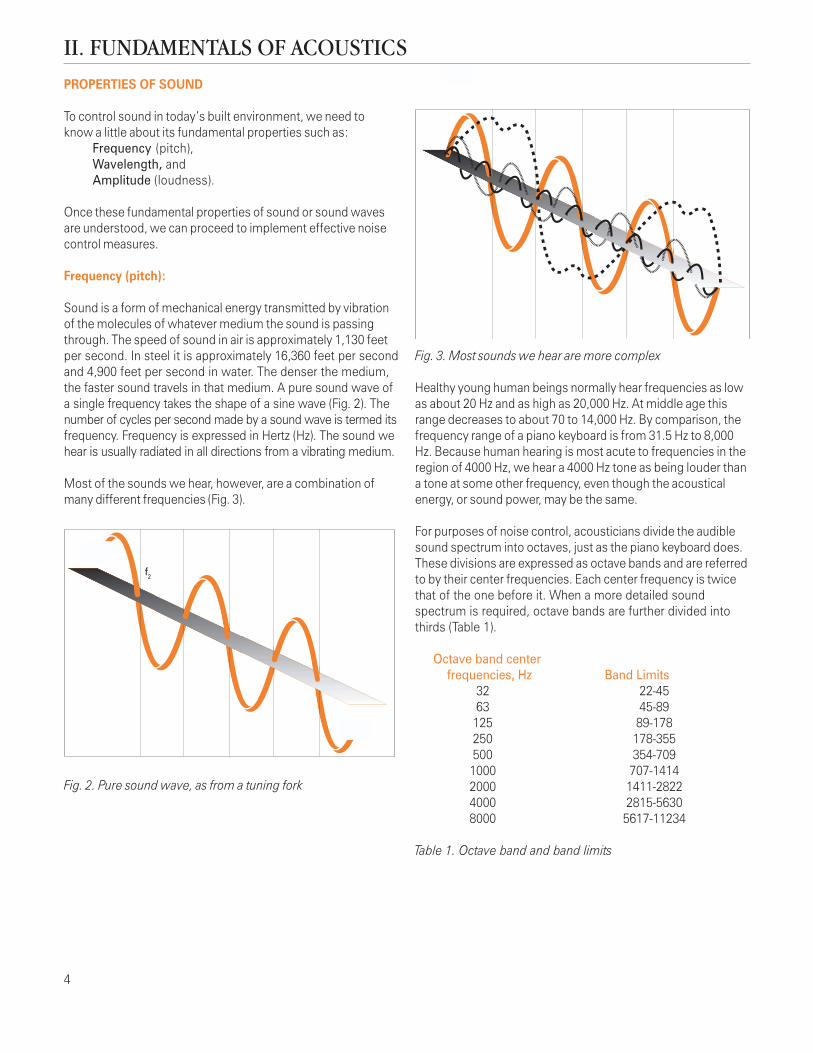
Sound is a form of mechanical energy transmitted by vibrationof the molecules of whatever medium the sound is passingthrough. The speed of sound in air is approximately 1,130 feetper second. In steel it is approximately 16,360 feet per secondand 4,900 feet per second in water. The denser the medium,the faster sound travels in that medium. A pure sound wave ofa single frequency takes the shape of a sine wave (Fig. 2). Thenumber of cycles per second made by a sound wave is termed itsfrequency. Frequency is expressed in Hertz (Hz). The sound wehear is usually radiated in all directions from a vibrating medium.
Most of the sounds we hear, however, are a combination ofmany different frequencies (Fig. 3).
Fig. 3. Most sounds we hear are more complex
Healthy young human beings normally hear frequencies as lowas about 20 Hz and as high as 20,000 Hz. At middle age thisrange decreases to about 70 to 14,000 Hz. By comparison, thefrequency range of a piano keyboard is from 31.5 Hz to 8,000Hz. Because human hearing is most acute to frequencies in theregion of 4000 Hz, we hear a 4000 Hz tone as being louder thana tone at some other frequency, even though the acousticalenergy, or sound power, may be the same.
For purposes of noise control, acousticians divide the audiblesound spectrum into octaves, just as the piano keyboard does.These divisions are expressed as octave bands and are referredto by their center frequencies. Each center frequency is twicethat of the one before it. When a more detailed soundspectrum is required, octave bands are further divided intothirds (Table 1).
Octave band center frequencies, Hz Band Limits
32 22-4563 45-89
125 89-178250 178-355500 354-7091000 707-14142000 1411-28224000 2815-56308000 5617-11234
Table 1. Octave band and band limits
II. FUNDAMENTALS OF ACOUSTICS
Fig. 2. Pure sound wave, as from a tuning fork
f2
4

5
Wavelength:
The wavelength of a sound wave is the distance between the startand end of a sound wave cycle or the distance between twosuccessive sound wave pressure peaks (Fig. 4). Numerically, it isequal to the speed of sound in the material such as air dividedby the frequency of the sound wave. For example:
The wavelength of a 100 Hz tone at room temperature is1130 ft/sec divided by 100 Hz which is equal to 11.3 ft.
Amplitude (loudness):
The amplitude or loudness of a sound wave is expressed byits sound pressure level. Sounds having the same wavelength(equal frequency) may have differing loudness (Fig. 5).
Because the sound pressure of a sound wave may vary over awide range—a change in magnitude of ten million to one—sound pressure is expressed using a logarithmic scale. This isthe basis of the decibel scale, which compresses the range ofsound pressure into a scale from 0 to 150. The decibel (dB) isnot an actual measure of amplitude or loudness, but expressesthe ratio between a given sound pressure and a referencesound pressure. This relationship is expressed by thefollowing equation: (Lp) = 10 log (P/Pre)2
Where: Lp is the Sound Pressure Level P is the Sound Pressure (Pa) Pre is the sound pressure at the threshold of hearing (0.00002 Pa)Table 2 gives sound pressure levels in dB and sound pressurein Pascal’s (Pa) for various sounds within the human ear’shearing range. Note that, because the decibel scale islogarithmic, a sound pressure level of 80 dB is 1,000 timesthat of the sound pressure level at 40 dB – not just threetimes.
Sound pressure Sound pressure,Source of noise level, dB PaThreshold of pain 120 20Loud rock music 110 6.3Metalworking plant 100 2Average street noise 70 0.06Average office noise 60 0.02Quiet residential street 50 0.006Very quiet home radio 40 0.002Inside a country home 30 0.0006Threshold of hearing 10 0.00006
Table 2. Sound pressure levels for various sounds
Fig. 5. Two sounds of equal frequency and differing amplitude.
Fig. 4. Wavelength: the distance from start to end of a cycle
AMPLITUDE
AMPLITUDE
FULL CYCLE
WAVELENGTH
Excessive noisein the classroom
is an unacceptablebarrier to learningwhich our society
can ill afford.Lou Sutherland, Acoustical Consultant
”
“

How we measure sound levels
A sound level meter (Fig. 6) is used to measure sound pressurelevels. Since the human ear is not equally sensitive to all soundlevels, most sound level meters have internal frequencyweighting systems to give readings equivalent to how we hearsound levels. These weighting systems are designated as A, B,and C weightings. Today only the A and C weightings are used.The A weighting is used most frequently because it yieldssound measurements that most closely reflect how we actuallyhear. These response curves, which plot the relative responsein dB against frequency in Hz, are shown in Figure 7.
Fig. 6. Sound level meter
Fig. 7. A, B, and C frequency weighting curves
Continuous exposure to A-weighted sound levels over 85 dBcan cause permanent hearing loss. It is possible, under perfectlistening conditions, for the human ear to detect changes insound level as little as 1 dB. However, a change of at least3 dB is normally required in order to be detectable. A 10 dBchange in sound level is commonly heard as twice as loud,or one-half as loud.
A noise control problem may involve multiple sources.For example, two motors may be located at the source, oneoperating steadily and the other intermittently. However, thetotal sound pressure level when both motors are operatingwill not be the total number of decibels produced by each,because decibels are not additive. The total sound pressurelevel when both motors are operating can be easilydetermined as shown in Table 3.
If the difference between Add to the higherthe two sound levels is: sound level:
1 dB or less 3 dB2 or 3 dB 2 dB4 to 9 dB 1 dB
10 dB or greater 0 dB
Table 3. Adding dB to sound levels for second source
For example: If both motors are emitting 65 dB, when thesecond motor is operating the total sound pressure level willbe 65 + 3 = 68 dB. If one motor is emitting 65 dB and theother 70 dB, when both motors are operating the total soundpressure level will be 70 + 1 = 71 dB.
If one motor is emitting 65 dB and the other 75 dB, when bothmotors are operating the total sound pressure level will remainat 75 dB, the sound level of the noisier motor.
How we hear sound
As noted, sounds at some frequencies are perceived as louderto the human ear than sounds at certain other frequencies,even though they may actually have the same dB level. Thisdemonstrates two interesting facts about how we hear:
1. The lower the frequency, the less sensitive the humanear is to it, especially sounds below 100 Hz.
2. The human ear is most sensitive to sounds around 4000 Hz.
OTHER SOUND PROPERTIES
How sound fluctuates with time can be an important factor innoise control. This fluctuation with time can take one of three forms:
1. Steady sound changing little or not at all with time, suchas the noise produced by a fan. We can become soaccustomed to steady sound that we almost cease tohear it after a while, unless it is too loud to ignore.
2. Intermittent sound, occurring more or less randomly withtime, such as a low flying airplane. Intermittent soundscan be more annoying than steady sounds because theyrepeatedly interrupt periods of relative quiet.
3. Sudden or impulsive sound, such as a gunshot, occurringunexpectedly and usually startling or even frightening thelistener. If loud enough, such sounds can cause hearing loss.
+5
0
-5
-10
-15
-20
-25
-30
-35
-40
-45
-5020 50 100 200 500 1000 2000 5000 10,000
REL
AT
IVE
RES
PO
NS
E -
DEC
IBEL
S
FREQUENCY - Hz
FREQUENCY RESPONSE FORU.S. WEIGHTING CHARACTERISTICS
C
B
A
B & C
A
6

7
Propagation:
Sound waves radiate directly and spherically outward from thesource (Fig. 8), decreasing in amplitude with the square of thedistance from the source. The sound pressure level decreases6 dB for each doubling of distance. If, however, the soundsource is indoors, reflected or reverberant sound will add tothe overall sound level within the room to make up for thedecreasing direct sound energy.
1m-6dB
2m-12dB
SOUNDSOURCE
THE AREAOF THE WAVEFRONT
AT d, (1m)
THE AREAOF THE WAVEFRONTIS 4 TIMES GREATER
AT d2, (2m)
Fig. 8. Direct sound energy decreases with the square of thedistance from the source
How much background sound is acceptable?
We have defined noise as unwanted sound. Whether weare in our homes, workplaces, or outdoors, we will almostcertainly be exposed to a certain level of background orambient sound. Before we can begin to solve a noise controlproblem, we must determine how much background soundis acceptable. We can never create, nor do we really want, acompletely sound-free environment. We do not wish to live ina world without sound.
The question becomes: at what level does background soundbecome too loud for a particular situation? A moderate levelof background sound can be helpful when it prevents privateconversation in the home or office from being overheard bynearby listeners, yet doesn’t make it difficult for those conversingto be heard by each other. Very low level background soundcan even contribute to sleep or rest when not interrupted byintermittent or sudden loud noises. In some public places, asomewhat higher level of background sound may be acceptable.Other places, such as auditoriums and concert halls where verylow background sound levels are required, present particularproblems in sound control.
Noise Criteria (NC) curves are one of several systems used toestablish allowable sound levels for various interior spaces. NCcurves are shaped to compensate for the human ear’s responseto loudness at octave band center frequencies and the speechinterference properties of noise. The NC curves are shown inFigure 9. Recommended NC sound levels for different spacesare shown in Table 4, page 8. Among other systems one mayencounter are RC (room criteria) curves, Free Field Loudnesscontours for pure tones, and Equal Loudness contours forrandom noise.
Detailed guidelines for determining allowable sound levels canbe found in Chapter 46, ASHRAE Handbook - Applications.
80
70
60
50
40
30
20
1063 125 250 500 1000 2000 4000 8000 OCTAVE BAND CENTER FREQUENCY (Hz)
NC-65
NC-60
NC-55
NC-50
NC-45
NC-40
NC-35
NC-30
NC-25
NC-20
NC-15SO
UN
D P
RE
SS
UR
E L
EV
EL
(dB
re2
0 m
Pa)
Fig. 9. Noise criteria curves for octave band center frequenciesfrom 63 Hz to 8000 Hz.
All materials areacoustical materials.
Some are better than others.Eric Unger and Richard Bolt, Acoustical Consultants
”“

Sound paths:
Sound waves can travel through any media—air, water, wood,masonry, or metal. Depending on the media through which ittravels, sound is either airborne or structureborne.
Airborne sound
Airborne sound radiates from a source directly into and travelsthrough the air. The sound of traffic passing our homes, thesound of music or voices from the next room or office, thenoise from low flying aircraft—all travel to our ears as airbornesound.
Type of space Acoustical considerations NC value
Concert and recital halls Listening to both loud and faint sounds 10 – 20Broadcast and recording studios Distant microphone pick-up 15 – 20Broadcast, television, and recording studios Close microphone pick-up 20 – 25Large auditoriums, theaters, churches Listening to speech and music 20 – 25Small auditoriums, theaters, churches Listening to speech and music 25 – 30Meeting, conference, and classrooms Clear speech communication among a group 25 – 30Bedrooms, apartments, hotels, motels Clear conversation with speech privacy 25 – 35Living rooms and family rooms Clear conversation among a small group 35 – 45Private offices Clear conversation with speech privacy 30 – 35Large offices, reception areas, retail shops Clear speech communication 35 – 50Lobbies, engineering rooms, secretarial areas Clear speech communication 40 – 45Kitchens, laundries, laboratories Clear speech communication 40 – 45Light maintenance shops, equipment rooms Clear speech communication 45 – 60
Table 4. Recommended noise criteria range for various interior spaces.
Structureborne sound
Structureborne sound travels through solid materials usually indirect mechanical contact with the sound source, or from animpact on that material. Examples are footsteps or objectsfalling on the floor upstairs, a knock at the door, or vibrationfrom loud speakers on the floor. All structureborne soundmust eventually become airborne sound in order for us tohear it. We can only feel structureborne sound as vibrations ina material. In most noise control situations, both airborne andstructureborne sound must be considered.
Three ways to control noise:
There are only three basic ways to attenuate or reduce sound,whether at the source, at the listener’s location, or along thepath it travels from the source to the receiver:
1. Replace the sound source with a quieter one.2. Block the sound with a solid, heavy material that resists
the transmission of sound waves.3. Absorb the sound with a light, porous material that soaks
up sound waves.
These three ways to control sound are discussed in more detailin the subsequent sections.
There’s a goodprobability that,
if you can’t see thenoise source,
you won’t hear it.Robert Coffeen, Acoustical Consultant
”
“
8

9
Airborne sound transmission loss
Airborne sound transmission loss is a measure of the degreeto which a material or construction can block or reducetransmission of sound from one area to another.
All materials block or attenuate sound energy to a degree—heavy,impervious materials more effectively than light, porous ones.Since today’s building technology depends to a great extent onlight, flexible products like gypsum board and lightweight steelframing, the challenge is to utilize these materials in designingassemblies that provide optimum acoustical performance yetdo not greatly increase the weight and mass of the structure.
Measuring sound transmission loss
The degree to which a material or construction is effective atblocking airborne sound is expressed as its sound transmissionloss (STL) value. Sound transmission loss values are measuredat each one-third octave band frequency from 125 to 4000 Hzand are expressed in dB. STL values are determined andmeasured in accordance with ASTM Standard E 90, StandardTest Method for Laboratory Measurement of Airborne SoundTransmission Loss of Building Partitions and Elements. Fromthe sound transmission loss values, a single number ratingcalled the sound transmission class (STC) is determined usingASTM Standard E 413, Standard Classification for Determinationof Sound Transmission Class.
The values above are based on a typical A-weightedbackground noise level of 30 dB and are based on multiplesof five. Constructions with STC values within 1 or 2 points ofwhat is required or specified should be considered acceptableas construction and test laboratory variations often exceed2 or more STC points.
Lightweight double-leaf walls
One of the most effective ways to block or reduce thetransmission of sound from one room to another is to build adouble-leaf wall. A double-leaf wall or sound transmissionloss barrier is any wall with two faces separated by studs.Because of their construction, most double-leaf walls weighless than solid walls with the same or comparable soundtransmission loss values. For this reason, they are calledlightweight walls. We describe double-leaf walls as“mass–spring–mass” walls because they have twomasses (faces) separated by air or studs (springs).
The sound transmission loss or STC values of a lightweightwall can be increased as much as 10 STC points by addingacoustical insulation to the stud cavity of the wall. Theacoustical insulation changes the spring properties of the“mass–spring–mass” composition of double-leaf walls. To getthe most effectiveness out of the insulation, completely fillthe stud cavity. Lightweight fiber glass insulation is anexcellent acoustical insulation to use in double-leaf walls.
III. AIRBORNE SOUND TRANSMISSION
Table 5 shows the relationship between STC and noise controleffectiveness.
STC Rating Speech Audibility Effectiveness
15 to 25 Normal speech easily understood Poor25 to 35 Loud speech easily heard, half of normal speech understood Marginal35 to 45 Half of loud speech understood, normal speech heard but not understood Good45 to 55 Loud speech faintly heard but not understood Very good55 and higher Loud speech usually not heard Excellent
Table 5. Relationship between STC and noise control effectiveness
”“If it sounds good,
it is good.Ron Moulder,
Acoustical Consultant
10
Sound transmission loss of double-leaf walls
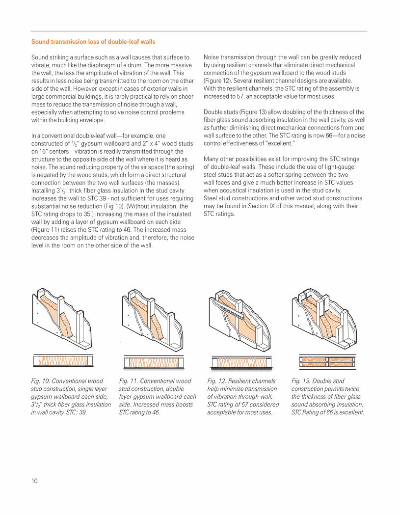
Sound striking a surface such as a wall causes that surface tovibrate, much like the diaphragm of a drum. The more massivethe wall, the less the amplitude of vibration of the wall. Thisresults in less noise being transmitted to the room on the otherside of the wall. However, except in cases of exterior walls inlarge commercial buildings, it is rarely practical to rely on sheermass to reduce the transmission of noise through a wall,especially when attempting to solve noise control problemswithin the building envelope.
In a conventional double-leaf wall—for example, oneconstructed of 1/2” gypsum wallboard and 2” x 4” wood studson 16” centers—vibration is readily transmitted through thestructure to the opposite side of the wall where it is heard asnoise. The sound reducing property of the air space (the spring)is negated by the wood studs, which form a direct structuralconnection between the two wall surfaces (the masses).Installing 31/2” thick fiber glass insulation in the stud cavityincreases the wall to STC 39 - not sufficient for uses requiringsubstantial noise reduction (Fig 10). (Without insulation, theSTC rating drops to 35.) Increasing the mass of the insulatedwall by adding a layer of gypsum wallboard on each side(Figure 11) raises the STC rating to 46. The increased massdecreases the amplitude of vibration and, therefore, the noiselevel in the room on the other side of the wall.
Noise transmission through the wall can be greatly reducedby using resilient channels that eliminate direct mechanicalconnection of the gypsum wallboard to the wood studs(Figure 12). Several resilient channel designs are available.With the resilient channels, the STC rating of the assembly isincreased to 57, an acceptable value for most uses.
Double studs (Figure 13) allow doubling of the thickness of thefiber glass sound absorbing insulation in the wall cavity, as wellas further diminishing direct mechanical connections from onewall surface to the other. The STC rating is now 66—for a noisecontrol effectiveness of “excellent.”
Many other possibilities exist for improving the STC ratingsof double-leaf walls. These include the use of light-gaugesteel studs that act as a softer spring between the twowall faces and give a much better increase in STC valueswhen acoustical insulation is used in the stud cavity.Steel stud constructions and other wood stud constructionsmay be found in Section IX of this manual, along with theirSTC ratings.
Fig. 10. Conventional wood Fig. 11. Conventional wood Fig. 12. Resilient channels Fig. 13. Double studstud construction, single layer stud construction, double help minimize transmission construction permits twicegypsum wallboard each side, layer gypsum wallboard each of vibration through wall. the thickness of fiber glass31/2” thick fiber glass insulation side. Increased mass boosts STC rating of 57 considered sound absorbing insulation.in wall cavity. STC: 39. STC rating to 46. acceptable for most uses. STC Rating of 66 is excellent.
11
Insulation density and STC
It is incorrect to assume that higher density insulation withinthe “mass/spring/mass” wall system provides better soundtransmission loss. Comparative tests conducted at nationallyrecognized acoustical laboratories have shown that increasingthe density of the insulation while maintaining a constantthickness does not have a significant effect on the STC ratingof the construction. It is incorrect to assume that heavyinsulation in the core of a double leaf wall increases the STCbecause it adds weight to the wall. To increase the STC of awall by adding weight, the weight must be added to the facesof the wall, not its core.
For this reason, mineral or rock wool insulation is not betterthan low-density fiber glass insulation. These same tests showthat insulation thickness within the wall cavity is the mostimportant property, and that complete filling of the cavitybetween wall surfaces provides the best wall performance.
Sound transmission loss and noise control
Other than reducing the noise level at the source, the bestway to resolve noise problems is to enclose the source withina housing constructed of materials having high soundtransmission loss values. The addition of an acousticallyabsorbent material to the inside of the enclosure reducessound transmission. For example, Table 6 gives effectivenoise reduction values in dB for an enclosure made of 1/2”plywood, with and without a lining of 2” fiber glass insulation:
Enclosures for source control may be fabricated on the site,or assembled from modular acoustic panel systems availablefrom several manufacturers. Whatever the system orconstruction, it should be designed and built so as to enclosetotally the noise source without air gaps; as noted, any gap inan acoustical construction that leaks air will also leak sound. Itshould be remembered that, when equipment is to beenclosed, it may be necessary to provide cooling air,combustion air, or both. Care must be taken to prevent noisefrom leaking out of the enclosure through air vents providedfor such purposes.
Sound flanking paths
When designing or selecting structures to reduce thetransmission of airborne sound, careful consideration mustbe given to flanking paths. Flanking paths are paths or routesthat sound can take in traveling from one space to anotherother than by way of the main assembly separating the twospaces. For instance, a door in a wall assembly could bea flanking path.
As noted, any gap in an acoustical structure that leaks air willalso leak sound. Sound leaks are flanking paths that can renderuseless an otherwise effective sound barrier. Typical flankingpaths include joints between walls and ceilings, floors, or otherwalls; poorly fitted, unsealed, or undercut doors and windows;and mechanical or electrical service fittings and openings.The following suggestions will help reduce flankingsound paths.
Doors: Hollow core doors are poor sound blockers. Whenprivacy is a key consideration, doors should be solid wood orhave insulated cores, and should be gasketed to prevent soundfrom passing between the door and the jamb or sill.
Windows: Double pane and/or storm windows reducesound transmission. Weather stripping helps. Windows facingexterior noise sources should be small and as few as possible.Double-hung windows should be able to be tightly closed.
Wiring and piping: Holes through which wiring or conduitpasses should be sealed or caulked. Cutouts for electricaloutlet boxes should be made precisely so boxes will fit snugly.Do not install electrical outlet boxes opposite each other oneach side of a wall; these should be staggered. In bathroomson opposite sides of a wall, medicine cabinets should bestaggered. Holes cut out for piping should be sealed withcaulking. Just stuffing the holes with insulation is not sufficient.Sound can easily pass through porous insulation. One can stuffthe holes with insulation and then caulk over the insulation.
EFFECTIVE NOISE REDUCTION VALUES, dB OCTAVE BAND CENTER FREQUENCIES, HzCONSTRUCTION DETAIL 125 250 500 1000 2000 4000
1/2” plywood, unlined 13 14 15 21 21 251/2” plywood, lined with 2” fiber glass 15 16 19 22 25 27
Table 6. Effective noise reduction values in dB for plywood enclosure with fiber glass insulation lining

Controlling sound transmission through floors is an importantpart of sound control in multi-story structures. In additionto the STC rating, which is related to airborne soundtransmission, floor/ceiling assemblies are assigned animpact insulation class (IIC) rating based on how well theyperform in reducing structureborne sound from impactsuch as footsteps or dropped objects. The IIC rating isdetermined by ASTM Standard E 989, Standard Classificationfor Determination of Impact Isolation Class (IIC). Test dataobtained in accordance with ASTM E 492, Standard TestMethod for Laboratory Measurement of Impact SoundTransmission Through Floor/Ceiling Assemblies Using theTapping Machine, is used to determine the IIC rating of a floor.
Cushioning floor impact with a carpet and pad is one of themost effective methods of improving the IIC of a floor/ceilingassembly, but this does not significantly improve the STC rating.To increase both the STC and IIC ratings of a floor/ceilingconstruction, fiber glass insulation should be installed in thejoist cavity, with a resilient ceiling system below the joists.The IIC rating of a floor/ceiling assembly should be equal toor better than its STC rating to achieve equal performance incontrolling both airborne and structureborne sound. Figure 14shows a typical floor/ceiling assembly.
IV. STRUCTUREBORNE SOUND TRANSMISSION
Fig. 14. Floor/ceiling assembly with carpet and pad, particleboard underlayment, plywood subfloor, resilient channels andgypsum board ceiling,with fiber glass insulation in joist cavities.STC = 53; IIC = 73.
12
There is nosuch thing as
good acousticsand bad acoustics:only appropriate
acoustics andinappropriate
acoustics.Robert Coffeen, Acoustical Consultant
”
“

13
Definitions
We have defined sound as a form of energy. Sound absorptionis the ability of a material to transform acoustical energy intosome other form of energy, usually heat. All materials absorbsome acoustical energy. Some materials such as gypsumboard absorb it poorly, reflecting most of the energy thatstrikes their surfaces, while other materials such as fiber glassinsulation absorb most of it.
Measuring sound absorption: The decimal fraction of thesound energy absorbed and not reflected by a material istermed its sound absorption coefficient. As materials absorbdifferent amounts of sound energy at different frequencies,sound absorption coefficients are measured at one-thirdoctave band center frequencies from 125 to 4000 Hz.
Building materials are generally rated by their noise reductioncoefficient (NRC). This single number rating is the average ofthe sound absorption coefficients of a material at 250, 500,1000, and 2000 Hz, rounded to the nearest .05. Soundabsorption coefficients and single number rating values aredetermined using ASTM Standard C 423, Standard Test Methodfor Sound Absorption and Sound Absorption Coefficients by theReverberation Room Method. A material is usually consideredto be a sound absorber if it has a NRC value greater than 0.35.
The sound absorption performance of a material is commonlypublished as a table of sound absorption coefficients at octaveband center frequencies from 125 to 4000 Hz. For example,Table 6 gives sound absorption data for CertainTeed CertaProTM
Commercial Board, Type CB 300.
A new single number rating for sound absorption that will bereplacing the NRC over the next several years is the soundabsorption average (SAA). This is the average of the soundabsorption coefficients of a material from 200 through 2500 Hzinclusive. As is the case with the NRC rating, a material isusually considered to be a sound absorber if it has a SAA valuegreater than 0.35.
Note that sound absorption tends to increase with materialthickness (but does not always do so). Also note that somevalues exceed 1.00. It is of course impossible for any materialto absorb more acoustical energy than that which strikes itssurface. However, sound absorption measurements of highlyabsorptive materials often yield sound absorption coefficientsgreater than 1.00 due to diffraction effects. These values arereported as required by the test standard. When using soundabsorption coefficients in calculations, values above 1.00should be reduced to values less than 1.00. Differences innoise reduction coefficients as small as 0.05 cannot bedetected by the human ear.
The sound absorption coefficients of a material are used tocalculate the sabins of absorption when that material is used.The sabin is the unit of measure of sound absorption in theEnglish system of units. It is equal to the sound absorptioncoefficient of a material times the area of the material used.For example, if a material has a sound absorption coefficient of0.57 at 500 Hz and 250 square feet of this material is used in aroom, then the sabins of absorption for this material at 500 Hzis 0.57 x 250 = 142.5 sabins. The sabins of absorption are usedto calculate noise reduction in a room and reverberation timewhich are discussed in later paragraphs.
To be an effective sound absorber, a material must haveinterconnecting air pockets or cells. Fiber glass insulation is avery good sound absorber because it has many interconnectingair pockets. Other effective sound absorbers, called resonators,typically employ small perforations or slots that allow sound toenter but not to escape easily. Wood slat panels and slottedconcrete masonry units operate on this principle.
Another type, the Helmholtz Resonator, is a chamber with asmall orifice, like a bottle; most of the sound entering thechamber is refracted within it and does not escape from it.Most resonators are effective only in a very narrow frequencyrange. Membranes or diaphragms stretched tightly over rigidperforated materials are also effective sound absorbers.
V. SOUND ABSORPTION
SOUND ABSORPTION COEFFICIENTS AT OCTAVE BAND CENTER FREQUENCIES, Hz
Type Thickness 125 250 500 1000 2000 4000 NRCCB 300 1” (25mm) 0.08 0.25 0.72 0.88 0.93 0.94 0.70(unfaced) 11/2” (38mm) 0.10 0.51 0.89 0.95 0.92 0.93 0.80
2” (51mm) 0.21 0.73 1.08 1.04 1.04 0.96 0.9521/2” (38mm) 0.31 0.81 1.08 1.02 1.04 1.03 1.003” (76mm) 0.41 0.96 1.13 1.03 1.03 1.02 1.0531/2” (89mm) 0.72 1.14 1.11 1.00 1.02 1.00 1.054” (102mm) 0.75 1.18 1.09 1.00 1.00 1.02 1.05
Table 6. Sound absorption data for CertaProTM Commercial Board,Type CB 300, unfaced
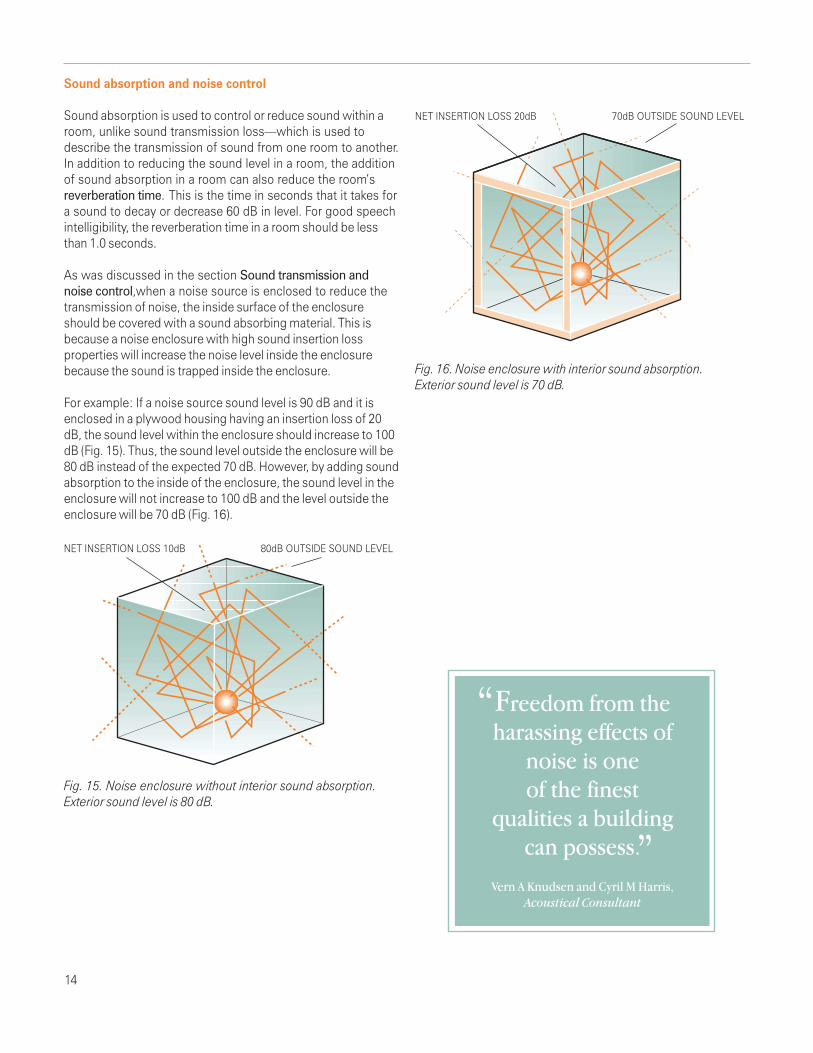
Sound absorption and noise control
Sound absorption is used to control or reduce sound within aroom, unlike sound transmission loss—which is used todescribe the transmission of sound from one room to another.In addition to reducing the sound level in a room, the additionof sound absorption in a room can also reduce the room’sreverberation time. This is the time in seconds that it takes fora sound to decay or decrease 60 dB in level. For good speechintelligibility, the reverberation time in a room should be lessthan 1.0 seconds.
As was discussed in the section Sound transmission andnoise control,when a noise source is enclosed to reduce thetransmission of noise, the inside surface of the enclosureshould be covered with a sound absorbing material. This isbecause a noise enclosure with high sound insertion lossproperties will increase the noise level inside the enclosurebecause the sound is trapped inside the enclosure.
For example: If a noise source sound level is 90 dB and it isenclosed in a plywood housing having an insertion loss of 20dB, the sound level within the enclosure should increase to 100dB (Fig. 15). Thus, the sound level outside the enclosure will be80 dB instead of the expected 70 dB. However, by adding soundabsorption to the inside of the enclosure, the sound level in theenclosure will not increase to 100 dB and the level outside theenclosure will be 70 dB (Fig. 16).
Fig. 15. Noise enclosure without interior sound absorption.Exterior sound level is 80 dB.
Fig. 16. Noise enclosure with interior sound absorption.Exterior sound level is 70 dB.
14
”
“Freedom from theharassing effects of
noise is oneof the finest
qualities a buildingcan possess.
Vern A Knudsen and Cyril M Harris,Acoustical Consultant
NET INSERTION LOSS 10dB 80dB OUTSIDE SOUND LEVEL
NET INSERTION LOSS 20dB 70dB OUTSIDE SOUND LEVEL

Sound level reduction calculation
This same principle can be used simply to reduce the soundlevel in a room. There is a simple relation between thereduction in sound level in a room and the amount of soundabsorption added to the room. This relationship can beexpressed in the following equation:
Reduction in sound level = 10 log AA/AB dBWhere: AA = sound absorption in sabins in the roomafter treatment, AB = sound absorption in sabins in theroom before treatment
For example, assume there is a room containing a noisymachine, and we want to decrease the noise level in the room.We can calculate how much the noise level will be reduced at aparticular frequency by using the above equation. If we installan acoustical ceiling in the room which now has only a gypsumboard ceiling, we can calculate the noise reduction in the room.Assume the ceiling is 600 sq. ft. and has an absorptioncoefficient of 0.26 at 250 Hz. We will assume that the sabins ofabsorption from all of the other surfaces in the room at 250 Hztotaled 60 sabins before the ceiling was installed (Fig. 17).When the ceiling is installed a total of 156 (0.27 x 600) sabinsare added to the room. Now, the total amount of sabins at 250Hz in the room is 60+156 = 216 sabins. Thus, the noise level inthe room is reduced by 5.5 dB(10log 216/60) by adding a soundabsorbing ceiling (Fig. 18).
Fig. 17. Room attenuation with gypsum board ceiling= 60 sabins at 250 Hz.
Fig. 18. Acoustical ceiling adds 156 sabins, reduces noise level5.5 dB.
Reverberation time calculation
The equation for calculating reverberation time is:Reverberation time(T60) = 0.049V/A secondsWhere: V = volume of the room, cu. ftA = sabins of absorption in the room
Using the room in the above example, we have a room volumeof 5,400 cu. ft (9x20x30 ft). The amount of sabins in the roombefore the acoustical ceiling is installed is 60 sabins at 250 Hz .Installation of the acoustical ceiling adds 156 sabins, for a totalof 216. Reverberation time in the room before the acousticalceiling is installed is 4.4 seconds. After the ceiling is installed,the reverberation time is 1.22 seconds. Now the lower rever-beration time in the room with the acoustical ceiling providesgood speech intelligibility.
A worksheet for calculating the room noise reduction andreverberation time is found in Section X of this manual.
15
60 SABINS ABSORPTION GYPSUM BOARD CEILING
216 SABINS ABSORPTION ACOUSTICAL CEILING

We have shown that sound travels from the source, alonga path, to the listener, or receiver. Hence the term SPR—source, path, receiver noise control. Control of noise thusinvolves three considerations: Acoustical treatment at thesource of noise; acoustical treatment of the path it travels—everything between the source and the receiver; andacoustical treatment at the receiver—where the listener is.
The solution to a specific noise control situation often involvesconsidering the problem from one, two, or all three of thesefactors. However, it is almost always best to start at thesource. That’s where the most effective solutions to noisecontrol are likely to be easily achieved at the lowest cost.
Controlling noise at the source:
Before designing acoustical treatment to attenuate noise at thesource, consider the following measures:
1. Moving the source to a more distant location or toanother area, where its noise will not reach anobjectionable level at the listener’s place.
2. Adjusting or modifying the source for quieter operation.If for example the source of noise is a mechanism suchas a fan or motor, it may be operated at a lower speed.
3. Repairing or servicing the noise source. It may be assimple a matter as lubricating gears, tensioning drivebelts, or tightening loose and vibrating screws or bolts.
4. Mounting the noise source on a resilient base (such assprings or soft pads) to isolate vibration and thusreduce the structureborne sound arriving at thelistener’s location.
5. Replacing the noise source with a quieter one. Modernappliances, for example, generally operate much morequietly than older models.
If these measures are not practical or, if attempted, fail to yieldsatisfactory results, the noise source should be enclosed withina housing having high sound transmission loss properties.Depending on the size of the noise source, such a housingmight be constructed of plywood, gypsum board, sheet metal,or fiber glass reinforced plastic.
We have shown that, if an enclosure with a high sound trans-mission loss value is lined with a material having a high soundabsorption value, the overall sound transmission loss value willbe increased and the overall noise reduction improved.
Obviously, if the noise source is outdoors—in the form of trafficnoise, aircraft, power lawnmower, or any other source overwhich we have no control, we cannot move, adjust, repair,service, or replace it. All we can do in that case is to try toreduce the noise along its path or at the receiver by building orretrofitting high sound transmission loss into the exterior wallsand roofs of our homes, offices, and public buildings toattenuate these outside noises. It should be emphasized that itis far less costly to design noise control into a structure at thebeginning than to retrofit after the building is built.
Controlling noise along its path:
Reflected sound may be reduced by placing sound absorbingmaterials on surfaces from which sound will be reflected (Fig. 21).
Fig. 21. Sound absorbing materials on walls, ceiling, and floor
Structureborne sound also travels along a path from source toreceiver (listener). Sound waves can set walls and otherstructures into vibration; this motion travels through thestructure and is re-radiated in the form of noise. The only wayto reduce structureborne noise along its path is to put vibrationbreaks in the structure. This treatment can be very expensive toinstall after a structure is built. It is more effective to preventvibration from entering a structure by isolating the source ofvibration from the structure.
Controlling noise at the receiver:
As noted, the first and most practical location for successfulnoise control is at the source. Other practical solutions tonoise control are often those involving treatment of thepath, which usually involves multiple components—direct,reflected, and flanking. If source control is not practical,another approach would be to treat the problem at thereceiver.
VI. PRINCIPLES OF SPR NOISE CONTROL
16

“Temporary” sound control
Direct ear protection (ear plugs or ear muffs) is often used toprotect workers’ hearing when source and path noise controlare not practical or possible. However, such measures areconsidered by the U. S. Occupational Safety and HealthAdministration to be “temporary;” in most instances, OSHAmandates “permanent” noise reduction measures. There is onlyone way to provide “permanent” receiver noise control, and thatis to enclose the listener in an acoustically effective enclosureor room.
The general principles of noise control at the source apply tonoise control at the receiver. However, there are additionalconcerns involved including such features as doors, windows,ventilation, and lighting. All of these features will be required inan acoustically effective workplace, and all present their ownsets of noise control problems.
Three steps to noise control solutions:
1. Locate the source of noise.
The first step in noise control is to investigate the real noisesource. It has been mentioned that noise control problems mayinvolve merely moving the source farther from the receiver,adjusting or repairing the source if it is a piece of noisy equipment,or replacing it. If none of these work, an acoustically efficientenclosure will have to be designed. Once the true source hasbeen identified, the next step is to measure the noise.
2. Measure the noise.
A sound level meter is used to measure the noise level atseveral locations—at its source, along its path, and at thereceiver or listener’s location—using the A-weighted scaleand also measuring the sound level in octave or third-octavebands. Sound level meter readings will not only provide soundpressure (loudness) levels at various locations, but will alsoshow which frequencies are most offensive to the listener.This data will be helpful in selecting acoustical materials withsound absorption and/or sound reduction properties bestsuited to the particular application.
3. Design the solution.
Once the noise source has been located, diagnosed, andmeasured, the solution can be designed. The first approach tosolving the problem should generally focus on source control,either by modifying the noise-producing element itself or bycovering it with an acoustical enclosure. If source attenuation isnot practical, possible, or sufficient to lower the sound pressurelevel at the receiver position, then controlling or reducing thenoise at the receiver should be considered. Usually, noisecontrol along the path should be considered only if it is notpossible to achieve the required noise reduction by sourceand receiver treatment.
Solving the noise problem may involve acoustic treatment atmore than one location. For example, acoustical enclosure ofthe noise source plus sound absorbing materials along thenoise path may be the most effective and economical way toreduce to an acceptable level the sound pressure at thereceiver location.
Designing a solution to the noise problem may involveconsideration of acoustical treatments that provide bothsound absorption and sound transmission loss properties.For example, a plywood housing enclosing the noise sourcemay provide adequate sound transmission loss performance,but its overall acoustical effectiveness will be improved by liningit with a sound absorbing material such as fiber glass insulation.
In any case, the services of a professional acoustical consultantwill be well worth their fee in terms of time and money saved,false starts avoided, noise problems solved, and productivityand comfort restored.
17
”
“The dollar cost of noise... is vague... althoughcertainly real enough.
But the loss inreal estate values
is plain for all to see.
R. A. Baron,The Tyranny of noise

If not acoustically treated, noise from heating, ventilating,and air-conditioning equipment can travel from room to roomin the home or in the office. Noise produced by fans and motorsof central air equipment can be transmitted throughout theduct system. High air velocities in the duct system can causenoise-producing turbulence. Also, turning vanes, dampers, andother elements inside the ducts; grilles and diffusers can whistleor rattle. HVAC ductwork can also act as a “speaking tube,”carrying conversations from one room or office into other spaces.
Noise from central equipment: When operating heating andair-conditioning equipment, a good guideline is “lower andslower:” lower volumes of air moved through the system withfans and blowers operating at a slower speed. Central airequipment should also be acoustically isolated from spaceswhere airborne noise would be objectionable. Equipmentshould be mounted on vibration isolators to avoid transmissionof structureborne noise. Sound traps or baffles will help toattenuate equipment noise in adjacent ductwork.
VII. HVAC NOISE CONTROL
Table 7 comparing sound attenuation in dB per lineal foot ofuninsulated sheet metal, sheet metal lined with fiber glass ductliner, and fiber glass duct board, shows significant perceivednoise reduction obtainable with fiber glass duct liner or ductboard. Note: Individual products are often compared by theirNRC values; however, differences of up to 0.1 in the NRCvalues published by their manufacturers have an insignificanteffect on the sound attenuation in the installed duct.
Table 7. Duct noise attenuation loss, dB per lineal foot
OCTAVE BAND CENTER FREQUENCIES, Hz125 250 500 1000 2000 4000
Uninsulated sheet metal ducts 0.1 0.1 0.1 0.1 0.1 0.1Sheet metal ducts with 1” duct liner 0.3 0.7 1.9 5.3 4.8 2.3Fiber glass duct board, 1” thick 0.4 1.4 3.3 3.9 5.0 3.7
18
Noise in air duct systems: Heating, ventilating, and air-conditioningductwork can be a source of noise as well as a transmitter ofit. Sheet metal ductwork without insulation can producepopping and banging noises due to expansion and contractioncaused by changes in air temperature. Components within theduct system, abrupt changes in direction, and restrictions inthe system can produce turbulence and air rush noise.
Most of these noise problems can be solved with fiber glassduct insulation in either of two forms:
1. Fiber glass duct liner, designed for installation insidesheet metal ductwork to attenuate air rush and centralequipment noise as well as to control heat loss or gainthrough duct walls.2. Fiber glass duct board, combining acoustical/thermalinsulation with a reinforced foil-kraft air barrier/vaporretarder, from which complete air duct systems may befabricated.
Fiber glass ducts wraps, used as thermal insulation on exteriorsof sheet metal ducts, provide little acoustical benefit except bymuffling the popping and banging noises when ducts undergotemperature changes.
Fig.Fig. 22. Significant noise reduction can be obtained by liningsheet metal ducts with fiber glass duct liner, or by fabricatingduct systems of fiber glass duct board.

19
1. Thinking you don’t have a noise problem.
In a factory you have a noise problem if a person is exposedto a noise level greater than an A-weighted level of 85 dB.Ear protectors should only be considered a temporarysolution to such a noise problem. Even lower levels could bea problem, such as a 55 dB level in a classroom. In general,if communications is difficult in a noisy area, you havea noise problem.
2. Not considering noise control before a project is started.
Although a source of noise can be treated after installation,it’s generally twice as expensive and half as effective comparedwith designing proper noise control into the system before thenoise source is installed.
3. Not conducting a detailed study of noisy equipment.
Most noisy equipment has several noise sources, all ofwhich must be considered. When analyzing noise sources,the spectrum of the noise from the equipment needs to bestudied. At minimum, octave band noise levels from theequipment should be obtained. You cannot solve a noiseproblem by knowing only the overall noise level generatedby the equipment.
4. Not using a systems approach to noise control.
A common waste of noise control dollars is the failure toconsider all possible solutions and noise paths. To treat onenoise source and not consider all possible noise sourcescould lead to unacceptable noise levels when a project iscompleted. The same is true if only one path of noisetransmission is considered. All airborne and structurebornenoise paths must be studied.
5. Not sealing air leaks.
Sound always takes the easiest path around or through abarrier. Construction gaps or air leaks are by far the easiestway for sound to pass from one space to another.
VIII. FIVE NOISE CONTROL MISTAKES TO AVOID
”
“In many instances itis no more expensiveto design a machineto operate quietly
than it isto design itto be noisy
George Diehl,retired Acoustical Engineer

20
Table I. ONE-THIRD OCTAVE BAND SOUND ABSORPTION COEFFICIENTS OF TYPICAL BUILDING MATERIALS
Product OCTAVE BAND CENTER FREQUENCIES,Hz125 250 500 1000 2000 4000 NRC
Brick, unglazed .03 .03 .03 .04 .05 .07 .05Brick, unglazed, painted .01 .01 .02 .02 .02 .03 .00Concrete block, painted .10 .05 .06 .07 .09 .08 .05Carpet, 1/8” pile height .05 .05 .10 .20 .30 .40 .15Carpet, 1/4” pile height .05 .10 .15 .30 .50 .55 .25Carpet, 3/16” combined pile and foam .05 .10 .10 .30 .40 .50 .25Carpet. 5/16” combined pile and foam .05 .15 .30 .40 .50 .60 .35Fabric, light velour, 10 oz/sq. yd. hung straight in contact with wall .03 .04 .11 .17 .24 .35 .15Fabric, medium velour, 14 oz/sq. yd. draped to half area .07 .31 .49 .75 .70 .60 .55Fabric, heavy velour, 18 oz/sq. yd. draped to half area .14 .35 .55 .72 .70 .65 .60Floors, concrete or terrazzo .01 .01 .01 .02 .02 .02 .00Floors, linoleum, asphalt, rubber or cork tile on concrete .02 .03 .03 .03 .03 .02 .05Floors, wood .15 .11 .10 .07 .06 .07 .10Floors, wood parquet in asphalt or concrete .04 .04 .07 .06 .06 .07 .05Glass, 1/4”, sealed, large panes .05 .03 .02 .02 .03 .02 .05Glass, 24 oz. operable windows, closed .10 .05 .04 .03 .03 .03 .05Gypsum board, 1/2”, nailed to 2x4s 16” on centers, painted .10 .08 .05 .03 .03 .03 .05Marble or glazed tile .01 .01 .01 .01 .02 .02 .00Plaster, gypsum or lime, rough finish or lath .02 .03 .04 .05 .04 .03 .05Plaster, gypsum or lime, smooth finish .02 .02 .03 .04 .04 .03 .05Plywood paneling, 1/4” thick, wood frame .58 .22 .07 .04 .03 .07 .10Water surface, as in swimming pool .01 .01 .01 .01 .02 .03 .00Wood roof decking, tongue-in-groove cedar .24 .19 .14 .08 .13 .10 .15
From Acoustical Ceilings—Use and Practice, Ceilings and Interior Systems Contractors Association (1984). p. 18.
IX. DATA TABLES
”
“If the acousticiandoes his job,
no one knowshe has been there.
Howard Kingsbury,Professor and Consultant
21
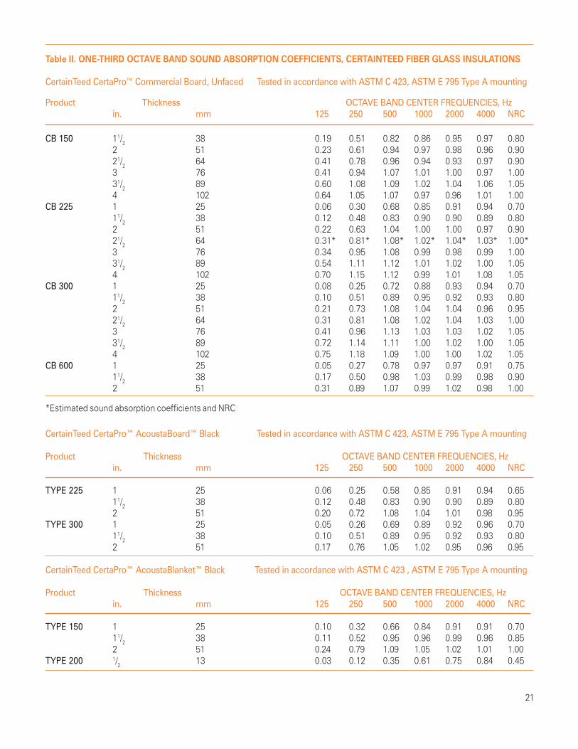
Table II. ONE-THIRD OCTAVE BAND SOUND ABSORPTION COEFFICIENTS, CERTAINTEED FIBER GLASS INSULATIONS
CertainTeed CertaPro™ Commercial Board, Unfaced Tested in accordance with ASTM C 423, ASTM E 795 Type A mounting
Product Thickness OCTAVE BAND CENTER FREQUENCIES, Hzin. mm 125 250 500 1000 2000 4000 NRC
CB 150 11/2 38 0.19 0.51 0.82 0.86 0.95 0.97 0.802 51 0.23 0.61 0.94 0.97 0.98 0.96 0.9021/2 64 0.41 0.78 0.96 0.94 0.93 0.97 0.903 76 0.41 0.94 1.07 1.01 1.00 0.97 1.0031/2 89 0.60 1.08 1.09 1.02 1.04 1.06 1.054 102 0.64 1.05 1.07 0.97 0.96 1.01 1.00
CB 225 1 25 0.06 0.30 0.68 0.85 0.91 0.94 0.7011/2 38 0.12 0.48 0.83 0.90 0.90 0.89 0.802 51 0.22 0.63 1.04 1.00 1.00 0.97 0.9021/2 64 0.31* 0.81* 1.08* 1.02* 1.04* 1.03* 1.00*3 76 0.34 0.95 1.08 0.99 0.98 0.99 1.0031/2 89 0.54 1.11 1.12 1.01 1.02 1.00 1.054 102 0.70 1.15 1.12 0.99 1.01 1.08 1.05
CB 300 1 25 0.08 0.25 0.72 0.88 0.93 0.94 0.7011/2 38 0.10 0.51 0.89 0.95 0.92 0.93 0.802 51 0.21 0.73 1.08 1.04 1.04 0.96 0.9521/2 64 0.31 0.81 1.08 1.02 1.04 1.03 1.003 76 0.41 0.96 1.13 1.03 1.03 1.02 1.0531/2 89 0.72 1.14 1.11 1.00 1.02 1.00 1.054 102 0.75 1.18 1.09 1.00 1.00 1.02 1.05
CB 600 1 25 0.05 0.27 0.78 0.97 0.97 0.91 0.7511/2 38 0.17 0.50 0.98 1.03 0.99 0.98 0.902 51 0.31 0.89 1.07 0.99 1.02 0.98 1.00
*Estimated sound absorption coefficients and NRC
CertainTeed CertaPro™ AcoustaBoard™ Black Tested in accordance with ASTM C 423, ASTM E 795 Type A mounting
Product Thickness OCTAVE BAND CENTER FREQUENCIES, Hzin. mm 125 250 500 1000 2000 4000 NRC
TYPE 225 1 25 0.06 0.25 0.58 0.85 0.91 0.94 0.6511/2 38 0.12 0.48 0.83 0.90 0.90 0.89 0.802 51 0.20 0.72 1.08 1.04 1.01 0.98 0.95
TYPE 300 1 25 0.05 0.26 0.69 0.89 0.92 0.96 0.7011/2 38 0.10 0.51 0.89 0.95 0.92 0.93 0.802 51 0.17 0.76 1.05 1.02 0.95 0.96 0.95
CertainTeed CertaPro™ AcoustaBlanket™ Black Tested in accordance with ASTM C 423 , ASTM E 795 Type A mounting
Product Thickness OCTAVE BAND CENTER FREQUENCIES, Hzin. mm 125 250 500 1000 2000 4000 NRC
TYPE 150 1 25 0.10 0.32 0.66 0.84 0.91 0.91 0.7011/2 38 0.11 0.52 0.95 0.96 0.99 0.96 0.852 51 0.24 0.79 1.09 1.05 1.02 1.01 1.00
TYPE 200 1/2 13 0.03 0.12 0.35 0.61 0.75 0.84 0.45

22
Table III. ONE-THIRD OCTAVE BAND SOUND TRANSMISSION LOSS VALUES, COMMON BUILDING MATERIALS
Product OCTAVE BAND CENTER FREQUENCIES, Hz125 250 500 1000 2000 4000 STC
Plywood, 1/2”, 1.33 lb/sq.ft. 17 20 23 23 23 24 21Plywood, 3/4”, 2.00 lb/sq.ft. 19 23 27 25 22 30 24
Sheet metal, 16 gauge, 2.38 lb/sq.ft. 18 22 28 31 35 41 31Sheet metal, 20 gauge, 1.50 lb/sq.ft. 16 19 25 27 32 39 27Sheet metal, 24 gauge, 1.02 lb/sq.ft. 13 16 23 24 29 36 25
Gypsum board, 1/2”, 1.80 lb/sq.ft. 18 22 26 29 27 26 26Gypsum board, 5/8", 2.20 lb/sq.ft, 19 22 25 28 22 31 26
Glass, single strength, 3/32", 1.08 lb/sq.ft. 15 18 25 26 28 29 26Glass, double strength, 1/8", 1.40 lb/sq.ft. 16 19 25 29 30 20 24Glass, plate, 1/4”, 2.78 lb/sq.ft. 20 25 26 30 23 30 27
Acrylic sheet, 1/8", 0.75 lb/sq.ft. 14 17 22 24 27 34 24Acrylic sheet, 1/4”, 1.45 lb/sq.ft. 16 19 26 27 30 29 27Acrylic sheet, 1/2”, 2.75 lb/sq.ft. 20 24 27 30 29 35 29
Lead vinyl, 1.25 lb/sq.ft. 17 19 28 30 34 39 29
Table IV. ONE-THIRD OCTAVE BAND SOUND TRANSMISSION LOSS VALUES, WOOD STUD WALL ASSEMBLIESData source: National Research Council of Canada
OCTAVE BAND CENTER FREQUENCIES, HzSingle 2”x4” studs, 16” centers 125 250 500 1000 2000 4000 STC
1 layer 1/2” Type X gypsum board each side 22 43 56 65 63 53 46Resilient channels on 24”centers31/2” CertainTeed fiber glass insulation
1 layer 5/8” Type X gypsum board each side 27 42 51 52 55 57 50Resilient channels on 24” centers31/2” CertainTeed fiber glass insulation
2 layers 1/2” Type X gypsum board one side 27 40 59 68 67 59 511 layer 1/2” Type X gypsum board other sideResilient channels on 24” centers31/2” CertainTeed fiber glass insulation
2 layers 5/8" Type X gypsum board one side 29 46 56 64 56 64 531 layer 5/8" Type X gypsum board other sideResilient channels on 24” centers31/2” CertainTeed fiber glass insulation

23
2 layers 1/2” Type X gypsum board both sides 33 51 61 69 70 64 57Resilient channels on 24” centers31/2” CertainTeed fiber glass insulation
2 layers 5/8” Type X gypsum board both sides 35 52 61 67 60 68 59Resilient channels on 24” centers31/2” CertainTeed fiber glass insulation
OCTAVE BAND CENTER FREQUENCIES, HzStaggered 2”x4” studs, 16” centers, on 2”x 6” wood plate 125 250 500 1000 2000 4000 STC
1 layer 1/2” Type X gypsum board both sides 21 41 50 59 61 57 4531/2” CertainTeed fiber glass insulation
1 layer 5/8” Type X gypsum board both sides 30 43 51 56 45 54 4831/2” CertainTeed fiber glass insulation
1 layer 5/8” Type X gypsum board one side 30 46 52 56 52 65 522 layers 5/8” Type X gypsum board other side31/2” CertainTeed fiber glass insulation
2 layers 1/2” Type X gypsum board both sides 31 49 57 62 66 64 5531/2” CertainTeed fiber glass insulation
2 layers 5/8” Type X gypsum board both sides 34 50 56 59 55 69 5631/2” CertainTeed fiber glass insulation
OCTAVE BAND CENTER FREQUENCIES, HzDouble 2”x4” studs, 16” centers, 2”x4” wood plates, 1/2” space between 125 250 500 1000 2000 4000 STC
1 layer 1/2” Type X gypsum board both sides 29 48 60 70 73 66 5331/2” CertainTeed fiber glass insulation

1 layer 1/2” Type X gypsum board both sides 34 50 64 77 85 79 582 layers 31/2” CertainTeed fiber glass insulation
1 layer 5/8” Type X gypsum board both sides 34 51 65 77 75 86 582 layers 31/2” CertainTeed fiber glass insulation
2 layers 1/2” Type X gypsum board one side 38 56 69 80 87 84 621 layer 1/2” Type X gypsum board other side2 layers 31/2” CertainTeed fiber glass insulation
2 layers 5/8” Type X gypsum board one side 40 52 61 72 70 84 621 layer 5/8” Type X gypsum board other side2 layers 31/2” CertainTeed fiber glass insulation
2 layers 1/2” Type X gypsum board both sides 42 61 73 81 86 85 662 layers 31/2” CertainTeed fiber glass insulation
2 layers 5/8” Type X gypsum board both sides 43 61 72 81 75 88 672 layers 31/2” CertainTeed fiber glass insulation
Table V. ONE-THIRD OCTAVE BAND SOUND TRANSMISSION LOSS VALUES, STEEL STUD WALL ASSEMBLIESData source: National Research Council of Canada
OCTAVE BAND CENTER FREQUENCIES, HzSingle 21/2” steel studs, 24” centers 125 250 500 1000 2000 4000 STC
1 layer 1/2” Type X gypsum board both sides 21 39 54 62 59 48 4521/2” CertainTeed AcoustaTherm batts
1 layer 5/8” Type X gypsum board both sides 20 41 55 61 50 52 4421/2” CertainTeed AcoustaTherm batts
2 layers 1/2” Type X gypsum board one side 27 44 58 65 63 54 511 layer 1/2” Type X gypsum board other side21/2” CertainTeed AcoustaTherm batts
2 layers 5/8” Type X gypsum board one side 27 46 59 64 52 56 511 layer 5/8” Type X gypsum board other side21/2” CertainTeed AcoustaTherm batts
OCTAVE BAND CENTER FREQUENCIES, HzDouble 2”x4” studs, 16” centers, 2”x4” wood plates, 1/2” space between 125 250 500 1000 2000 4000 STC
24

25
OCTAVE BAND CENTER FREQUENCIES, HzSingle 21/2” steel studs, 24” centers 125 250 500 1000 2000 4000 STC
2 layers 1/2” Type X gypsum board both sides 33 45 59 65 66 58 5521/2” CertainTeed AcoustaTherm batts
2 layers 5/8” Type X gypsum board both sides 32 48 61 64 56 59 5821/2” CertainTeed AcoustaTherm batts
OCTAVE BAND CENTER FREQUENCIES, HzSingle 35/8” steel studs, 24” centers 125 250 500 1000 2000 4000 STC
1 layer 1/2” Type X gypsum board both sides 26 37 52 60 63 49 4831/2” CertainTeed Acousta Therm batts
1 layer 5/8” Type X gypsum board both sides 26 44 58 65 50 55 5031/2” CertainTeed AcoustaTherm batts
2 layers 1/2” Type X gypsum board one side 31 42 56 63 65 53 521 layer 1/2” Type X gypsum board other side31/2” CertainTeed AcoustaTherm batts
2 layers 5/8” Type X gypsum board one side 31 47 61 68 59 57 551 layer 5/8” Type X gypsum board other side31/2” CertainTeed AcoustaTherm batts
2 layers 1/2” Type X gypsum board both sides 31 48 61 68 65 58 5531/2” CertainTeed AcoustaTherm batts
2 layers 5/8” Type X gypsum board both sides 35 50 62 69 60 62 5831/2” CertainTeed AcoustaTherm batts
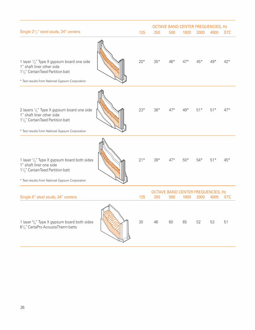
OCTAVE BAND CENTER FREQUENCIES, HzSingle 21/2” steel studs, 24” centers 125 250 500 1000 2000 4000 STC
1 layer 1/2” Type X gypsum board one side 20* 35* 46* 47* 45* 49* 42*1” shaft liner other side11/2” CertainTeed Partition batt
* Test results from National Gypsum Corporation
2 layers 1/2” Type X gypsum board one side 23* 38* 47* 49* 51* 51* 47*1” shaft liner other side11/2” CertainTeed Partition batt
* Test results from National Gypsum Corporation
1 layer 1/2” Type X gypsum board both sides 21* 39* 47* 50* 54* 51* 45*1” shaft liner one side11/2” CertainTeed Partition batt
* Test results from National Gypsum Corporation
OCTAVE BAND CENTER FREQUENCIES, HzSingle 6” steel studs, 24” centers 125 250 500 1000 2000 4000 STC
1 layer 5/8” Type X gypsum board both sides 30 46 60 65 52 53 5161/4” CertaPro AcoustaTherm batts
26

27
OCTAVE BAND CENTER FREQUENCIES, HzChase walls – double steel stud, 24” centers 125 250 500 1000 2000 4000 STC
1 layer 1/2” Type X gypsum board both sides 30 45 57 69 74 61 54Two 21/2” CertaPro AcoustaTherm batts
1 layer 5/8” Type X gypsum board both sides 31 48 58 69 60 64 55Two 21/2” CertaPro AcoustaTherm batts
2 layers 1/2” Type X gypsum board both sides 40 52 61 71 78 70 62Two 21/2” CertaPro AcoustaTherm batts
2 layers 5/8” Type X gypsum board both sides 40 55 63 73 67 74 64Two 21/2” CertaPro AcoustaTherm batts

Guide Specification
Part 1 - General
1.01 Summary
A. Provide glass fiber acoustical insulation as indicated inbuilding plans.
1.02 Materials Provided in Other Sections
These sections are typically cross-referenced. Delete sectionsnot included in project manual.[A. Section 09250 – Gypsum Board][B. Section 09260 – Gypsum Board Systems][C. Section 09100 – Metal Support Systems]
1.03 References
A. ASTM Standards1. ASTM E 90, Laboratory Measurement of Airborne
Sound Transmission Loss of Building Partitions2. ASTM E 413, Rating Sound Insulation3. ASTM E 84, Test Method for Surface Burning
Characteristics of Building Materials4. ASTM E 119, Method for Fire Tests of Building
Construction Materials5. ASTM E 136, Test Method for Behavior of Materials in
a Vertical Tube Furnace at 750°C6. ASTM C 518, Test Method for Steady State Thermal
Transmission Properties by Means of the Heat Flow Meter7. ASTM C 665, Specification for Mineral Fiber Blanket
Thermal Insulation for Light Frame Construction andManufactured Housing
1.04 Submittals
A. Product Data: Submit manufacturer’s product literature,samples and installation instructions for specified insulation.
1.05 Delivery, Storage and Handling
A. Protect insulation from physical damage and from becomingwet, soiled, or covered with ice or snow. Comply withmanufacturer’s recommendations for handling, storage andprotection during installation.B. Label insulation packages to include material name,production date and/or product code.Delete paragraph below if sections 01600 or 01620 are notincluded in project manual.[C. Deliver and store materials under provisions of section(01600) (01620).]
1.06 Limitations
A. Do not use unfaced insulation in exposed applicationswhere there is potential for skin contact and irritation.
Part 2 – Products
2.01 Manufacturer
A. CertainTeed Corporation, Valley Forge, PA.
2.02 Material
(Specify name of CertainTeed fiber glass acousticalinsulation product)
A. Type: Unfaced fiber glass acoustical insulation complyingwith ASTM C 665.B. Combustion characteristics: Passes ASTM E 136 test.C. Surface burning characteristics:
1. Maximum flame spread: 25.2. Maximum smoke developed: 50
when tested in accordance with ASTM E 84.*D. Fire resistance rating: Passes ASTM E 119 test.E. Sound transmission class of the assembly: STC =F. Size of insulation:
1. Thickness,2. Width,3. Length,
2.03 Gypsum Board
A. Refer to Section (09250) (09260) for detailed specifications.Select appropriate construction:[B. Type: 1/2” thick, Type X gypsum panels][C. Type: 5/8” thick, Type X gypsum panels]
2.04 Metal Framing
A. Refer to Section (09250) (09260) for detailed specifications.Select appropriate construction:[B. Type: 21/2” steel stud][C. Type: 35/8” steel stud]
28
X. APPENDIX

Part 3 – Execution
3.01 Inspection and Preparation
A. Examine substrates and conditions under which insulationwork is to be performed. A satisfactory substrate is one thatcomplies with requirements of the section in which substrateand related work is specified.B. Obtain installer’s written report listing conditions detrimentalto performance of work in this section. Do not proceed withinstallation until unsatisfactory conditions have been corrected.C. Clean substrates of substances harmful to insulation.
3.02 Installation – General
A. Comply with manufacturer’s instructions for particularconditions of installation in each case.B. Batts may be friction-fit in place until the interior finish isapplied. Install batts to fill entire stud cavity. If stud cavity isless than 96” in height, cut lengths to friction-fit against floorand ceiling tracks. Walls with penetrations require thatinsulation be carefully cut to fit around outlets, junction boxesand other irregularities.C. Where insulation must extend higher then 8 feet,supplementary support can be provided to hold product inplace until the interior finish is applied.
*This standard is used solely to measure and describe theproperties of products in response to heat and flame undercontrolled conditions. These numerical ratings are notintended to reflect hazards presented by this or any othermaterial under actual fire conditions. Values are reportedto the nearest 5 rating.
GLOSSARY OF ACOUSTICAL TERMS
Acoustical material: Any material considered in terms of itsacoustical properties. Commonly and especially, a materialdesigned to absorb sound.
Airborne sound: Sound which arrives at the point of concern,such as one side of a wall, by propagation through air.
A-weighted sound level (dB): The most common single numberrating system for measuring the loudness of a noise. It maybe read directly on most sound level meters by selecting thedesignated scale. It is obtained by applying the A-weightedfrequency response curve to the measured sound. Theresponse curve is indicative of the way humans respond todifferent frequencies.
Attenuation: The reduction in magnitude of airborne soundpressure level between two points in the sound transmissionpath from source to receiver.
Background noise: Noise from all sources unrelated to aparticular sound that is the object of interest. Background noisemay include airborne, structureborne, and instrument noise.
Decibel (dB): The term used to identify ten times the com-mon logarithm of the ratio of two like quantities proportionalto power or energy. (See Sound transmission loss.) Thus, onedecibel corresponds to a power ratio of (10 to the 0.1 power)to the n power. Note: Since the decibel expresses the ratio oftwo like quantities, it has no dimensions. It is, however,common practice to treat “decibel” as a unit, as for examplein the sentence: “The average sound pressure level in theroom is 45 decibels.”
Diffuse sound field: The sound in a region where the intensityis the same in all directions and at every point.
Direct sound field: The sound that arrives directly from asource without reflection.
Flanking transmission: The transmission of sound betweentwo rooms by any path other than directly through a commonpartition.
Frequency: The number of cycles per second measured inunits of Hertz (Hz). One hertz is one complete oscillation persecond. A frequency of 1000 Hz means 1000 cycles persecond.
Impact insulation class (IIC): A single number rating derivedfrom measured values of normalized impact sound pressurelevels in accordance with Annex 1 of ASTM Method E 492,Laboratory Measurement of Impact Sound TransmissionThrough Floor-Ceiling Assemblies Using the Tapping Machine.It provides an estimate of the impact sound insulationperformance of a floor-ceiling assembly.
Noise: Unwanted sound.
Noise isolation class (NIC): A single number rating calculatedfrom measured values of noise reduction as though they werevalues of transmission loss. The NIC determined in accordancewith ASTM standard E 413, Determination of Sound TransmissionClass. It provides an estimate of the sound isolation betweentwo enclosed spaces that are acoustically connected.
Noise reduction (NR): In a specified frequency band, thedifference between the space-time average sound pressurelevels produced in two enclosed spaces or one of them.Note: it is implied that in each room individual observationsare randomly distributed about the average value, with nosystematic variation within the position within the permissiblemeasurement region. Noise reduction becomes meaninglessand should not be used in situations where this condition isnot met.
29
Noise reduction coefficient (NRC): A single number ratingderived from measured values of sound absorption coefficientsin accordance with ASTM Test Method C 423, Sound Absorptionand Sound Absorption Coefficients by the Reverberation RoomMethod. It provides an estimate of the sound absorptiveproperty of an acoustical material. NRC values range from 0 forhard, reflective materials such as flat glass and gypsum boardto 1.2 for several inches of highly efficient fiber glass.
Octave band: A range of frequency where the highest frequencyof the band is double the lowest frequency of the band. Theband is usually specified by the center frequency.
Reverberation: The persistence of sound in an enclosed orpartially enclosed space after the source of the sound hasstopped.
Reverberation time: The time required for the average soundintensity of an enclosed space to decrease by 60 dB after thesound source becomes silent.
Sabin: The unit of measure of sound absorption in theinch-pound system.
Sound absorption average (SAA): A single number ratingsimilar to the NRC used to express the sound absorbingproperties of a material. It is equal to the average of the soundabsorption coefficients of a material from 200 through 2500 Hz.
Sound absorption coefficient (a, dimensionless): Metric sabin/m2 of a surface, in a specified frequency band, The measure ofthe absorptive property of a material as approximated byASTM Test Method C 423, Sound Absorption and SoundAbsorption Coefficients by the Reverberation Room Method.Ideally, the fraction of the randomly incident sound powerlevel absorbed or not otherwise reflected.
Sound attenuation: (1) The reduction of the intensity of asound as it travels from the source to a receiving location.Sound absorption is often involved as, for instance, in a linedair duct. (2) Spherical spreading and scattering or otherattenuation mechanisms.
Sound level meter: An instrument that measured soundpressure levels with a microphone which converts soundpressure waves to an electrical signal.
Sound pressure level (Lp): Of airborne sound, ten times thecommon logarithm of the ratio of the square of the soundpressure under consideration to the square of the standardreference pressure of 20 microPa. The quantity so obtainedis expressed in decibels.
Sound transmission class (STC): A single number ratingderived from measured values of transmission in accordancewith ASTM Classification E 413, Determination of SoundTransmission Class. It provides an estimate of the performanceof a partition in certain common sound insulation problems.
Sound transmission loss (STL): Of a partition, in a specifiedfrequency band, the times the common logarithm of the ratioof the airborne sound power incident on the partition to thesound power transmitted by the partition and radiated on theother side. The quantity so obtained is expressed in decibels.Note: Unless qualified, the term denotes the sound transmissionloss obtained when the specimen is exposed to a diffusesound field as approximated in reverberation rooms meetingthe requirements of ASTM Test Method E 90, LaboratoryMeasurement of Airborne Sound Transmission Loss ofBuilding Partitions.
Speech intelligibility: The proportion of meaningful speechthat is correctly interpreted by a listener.
Structureborne sound: Sound that arrives at the point ofconcern by propagation through a solid structure.
30
”“Let the word
be heard.
Anne Seltz, Audiologist
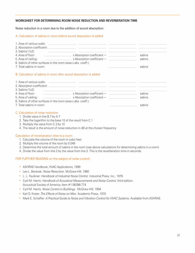
WORKSHEET FOR DETERMINING ROOM NOISE REDUCTION AND REVERBERATION TIME
Noise reduction in a room due to the addition of sound absorption:
A. Calculation of sabins in room before sound absorption is added
1. Area of various walls:2. Absorption coefficient:3. Sabins (1x2):4. Area of floor: x Absorption coefficient = sabins5. Area of ceiling: x Absorption coefficient = sabins6. Sabins of other surfaces in the room (area x abs. coeff.):7. Total sabins in room: sabins
B. Calculation of sabins in room after sound absorption is added
1. Area of various walls:2. Absorption coefficient:3. Sabins (1x2):4. Area of floor: x Absorption coefficient = sabins5. Area of ceiling: x Absorption coefficient = sabins6. Sabins of other surfaces in the room (area x abs. coeff.):7. Total sabins in room: sabins
C. Calculation of noise reduction1. Divide value in line B.7 by A.72. Take the logarithm to the base 10 of the result from C.13. Multiply the value from C.3 by 104. The result is the amount of noise reduction in dB at the chosen frequency
Calculation of reverberation time in a room:1. Calculate the volume of the room in cubic feet.2. Multiply the volume of the room by 0.0493. Determine the total amount of sabins in the room (see above calculations for determining sabins in a room)4. Divide the value from line 2 by the value from line 3. This is the reverberation time in seconds.
FOR FURTHER READING on the subject of noise control:
• ASHRAE Handbook, HVAC Applications, 1999• Leo L. Beranek: Noise Reduction. McGraw-Hill, 1960• L. L. Faulkner: Handbook of Industrial Noise Control. Industrial Press, Inc., 1976• Cyril M. Harris: Handbook of Acoustical Measurements and Noise Control, third edition.
Acoustical Society of America, Item #1-56396-774• Cyril M. Harris: Noise Control in Buildings. McGraw-Hill, 1994• Karl D. Kryter: The Effects of Noise on Man. Academic Press, 1970• Mark E. Schaffer: A Practical Guide to Noise and Vibration Control for HVAC Systems. Available from ASHRAE.
31

CertainTeed CertaProTM fiber glass insulations for commercialacoustical/thermal applications
CertainTeed Corporation manufactures a complete line of fiberglass insulation for new and existing commercial buildings.This CertaProTM line provides excellent acoustical and thermalperformance. Here are brief descriptions; for complete information,ask for CertaPro Catalog 30-25-031.
AcoustaThermTM Batts
Unfaced, light-density fiber glass battsdesigned for use in steel construction. Battsfor interior walls designed for friction-fitinstallation. Unfaced or kraft faced ceilingbatts designed to lie directly on ceilingsuspension systems. Faced batts have no
tabs; they are installed butted together. Used to enhanceacoustical and thermal performance of exterior and interior walls;to improve sound transmission loss performance of suspendedceiling systems. R-values from 8 to 30 (RSI: 1.41 to 5.28).
Partition Batts
Unfaced, light-density fiber glass batts11/2” (38mm) thick, for use in steel studconstruction. Sized for friction-fit installation.Will not rot or mildew; resists fungal growth.Rated noncombustible per ASTM E 136.Used to enhance acoustical and thermal
performance of shaftwalls and low-profile partition walls. R-value:5.8 (RSI: 1.02).
Thermal Kraft Faced Batts
Light-density fiber glass batts with a kraftvapor retarder facing. Lightweight; easilyfabricated and installed. Will not rot or mildew;resists fungal growth. Used to improvethermal performance of exterior and interiorwalls and floor/ceiling assemblies in non-
exposed applications. R-values: 11, 19 (RSI: 1.94, 3.35).
Thermal Foil Faced Batts
Light-density fiber glass batts with a foilvapor retarder facing. Lightweight; easilyfabricated and installed. Will not rot or mildew;resists fungal growth. Used to improvethermal performance of exterior and interiorwalls and floor/ceiling assemblies where FHC
75/450 rating is required. R-values from 11 to 38 (RSI: 1.94 to 6.69).
Thermal FSK-25 Faced Batts
Light-density fiber glass batts with a foil/scrim/kraft (FSK) fire resistant vapor retarder facing.Lightweight; easily fabricated and installed.Used to improve thermal performance ofexterior and interior walls and floor/ceilingassemblies where a FHC rating of 25/50 is
required. R-values: 11, 19 (RSI: 1.94, 3.35).
Thermal Extended Flange Batts
Light-density faced fiber glass blankets with4” (102mm) flange facings. Three facings:black or white poly/scrim/kraft (PSK), foil/scrim/kraft (FSK). They increase sound transmissionclass (STC) ratings and add thermal performancebelow panel wood deck roof systems. Class A,
Class I, FHC 25/50 rated surface for exposed applications. R-values:19, 30 (RSI: 3.35, 5.28).
Commercial Board: Unfaced, FSK Faced, ASJ Faced
Boards of resin bonded glass fibers in arange of densities. Unfaced boards for usewhere exterior finish is applied. Foil/scrim/kraft (FSK) faced boards provide a cleanmetallic finish. All service jacket (ASJ) facedboards provide a white finish. Adds sound
absorption properties to interior spaces. For exposed ornon-exposed applications requiring FHC 25/50 rating. R-valuesfrom 6 to 17.4 (RSI: 1.96 to 3.06).
AcoustaBoardTM Black
Rigid glass fiber board with an abuseresistant black non-woven facing. Class A,Class I, FHC 25/50 rated surface for exposedapplications. Used for sound control intheaters, sound studios, and entertainmentfacilities in applications requiring an exposed,
black faced sound absorbing insulation. Deep black facing.R-values: 4.3, 6.5, 8.7 (RSI: 0.76, 1.14, 1.53).
AcoustaBlanketTM Black
Black glass fiber blanket with an abuseresistant black surface. Class A, Class I, FHC25/50 rated surface for exposed applications.Used for sound control in theaters, soundstudios and entertainment facilities whichrequire a black sound absorbing insulation.
R-values from 2.1 to 8.3 (RSI: 0.37 to 1.46).
32
CertainTeed Acoustical Insulations

Other CertainTeed products that provide effective noisecontrol solutions in commercial construction
CertainTeed Corporation also manufactures fiber glassacoustical/thermal insulations for application to HVAC systems.CertainTeed’s ECOPHON® Commercial Ceiling Systems andwall panels combine acoustical performance with high aestheticvalues and integrated lighting. For additional information, seepublication references for each product as given below.
CertainTeed ToughGardTM Duct Board with Enhanced Surface
Rigid boards of resin bonded glass fibers witha reinforced foil laminate air barrier/vaporretarder and a tough, durable, fire-resistantblack composite air stream surface. Used tofabricate supply and return air ducts forcommercial and residential heating, ventilating
and air-conditioning systems. Provides thermal and acousticalinsulation along with substantially air-tight, quiet air delivery.Request Publication 30-34-006.
CertainTeed Ultra*DuctTM Gold Duct Board
Rigid boards of resin bonded glass fiberswith a reinforced foil laminate air barrier/vapor retarder. Used to fabricate supply andreturn air ducts for commercial and residentialheating, ventilating and air-conditioningsystems. Provides thermal and acoustical
insulation along with substantially air-tight, quiet air delivery.Request Publication 30-34-001.
CertainTeed ToughGardTM Duct Liner with Enhanced Surface
Acoustical and thermal insulation blanketcomposed of long textile-type glass fibersfirmly bonded together with a thermosettingresin. The air stream surface is overlaid withan extremely tough, durable, fire-resistantblack composite. Used as acoustical and
thermal insulation for lining sheet metal heating, ventilatingand air-conditioning ducts. Request Publication 30-33-008.
CertainTeed ToughGardTM R Duct Liner with Enhanced Surface
Acoustical and thermal insulation blanketcomposed of rotary type glass fibers bondedtogether with a thermosetting resin. The airstream surface is an extremely tough, durable,fire-resistant black composite. Used asacoustical and thermal insulation for lining
sheet metal heating, ventilating and air-conditioning ducts.Request Publication 30-33-011.
CertainTeed ToughGardTM Rigid Duct Liner Board
Acoustical and thermal insulation boardcomposed of glass fibers bonded togetherwith a thermosetting resin. The air streamsurface is an extremely tough, durable,fire-resistant black composite. Used asacoustical and thermal insulation for lining
large sheet metal heating, ventilating and air-conditioningducts and plenums. Request Publication 30-33-005.
CertainTeed Insul-Safe® 4 Fiber Glass Blowing Insulation
Loose fill insulation applied using pneumaticblowing machines. For installation in openblow or closed cavities covered with nettingor fabric. Used to provide acoustical andthermal performance in open (ceiling) cavities,and to add acoustical and thermal performance
to wall cavities in new commercial construction. Approved for usewith the Blow-In-Blanket® system. Request Publication 30-24-231.
Acoustical Ceiling Batts
CertaSoundTM Acoustical Ceiling Batts aredesigned to lie directly on suspendedceilings, providing excellent thermalprotection and acoustical performance.They are available unfaced or with kraftfacing. Kraft-faced CertaSoundTM
Acoustical Ceiling Batts, due to their intended application,have no stapling flanges. Request Publication 30-21-1319
OPTIMA® Loose Fill Fiber Glass Insulation for Closed CavityApplications
High quality unbonded, non-settling whitevirgin fiber glass designed for pneumaticinstallation in closed cavities covered withnon-woven OPTIMA fabric or equivalent.Used to add acoustical and thermalperformance to wall cavities in new
commercial construction or as retrofit insulation in enclosed,uninsulated construction assemblies. Request Publication30-24-216.
ECOPHON® Commercial Ceiling Systems
High density resin bonded glass wool ceilingtiles, wall panels, and baffles in a variety ofedge details. The system combines acousticalperformance and high aesthetic values withintegrated lighting in a fully demountableconcealed-grid system for commercial
applications. For additional information contact ECOPHON®
using their toll free telephone number: 1-877-258-7845.

CertainTeed CorporationA Saint-Gobain Company
P.O. Box 860Valley Forge, PA 19482
1-800-233-8990www.certainteed.com
Fax-on-demand: 1-800-947-0057
Code No. 30-25-047 © 2003 Certain Teed Corporation 10/03
Since 1904
Celebrating a Century of Building America