Embed Size (px)
Citation preview

ACTIVITY
Lecture (3 hours)
WEEK 6
At the end of this lecture/week, the students
will be able to :
LEARNING OUTCOMES
Learning Outcomes :
1. Discuss the purpose and objectives of engineering properties tests in the context of designing geotechnical structures
2. Determine important engineering properties of soils based on the analysis of laboratory test data
Week 6 : (3HL) Coverage : Laboratory tests to
determine engineering properties of soils : Strength,
Compressibility and Permeability
1.0 Overview
2.0 Scope of laboratory test
3.0 Mechanical properties tests
and their application
OUTLINE of PRESENTATION
LABORATORY TESTING

Based on the soil exploration works carried
out two types of samples are normally
retrieved from the site. These are disturbed
and undisturbed samples.
1.0 Overview.
The engineer/designer must specify the
tests that need to be carried out in the
laboratory so that relevant and appropriate
parameters are obtained to be used in the
design of the geotechnical structures.
LABORATORY TESTING

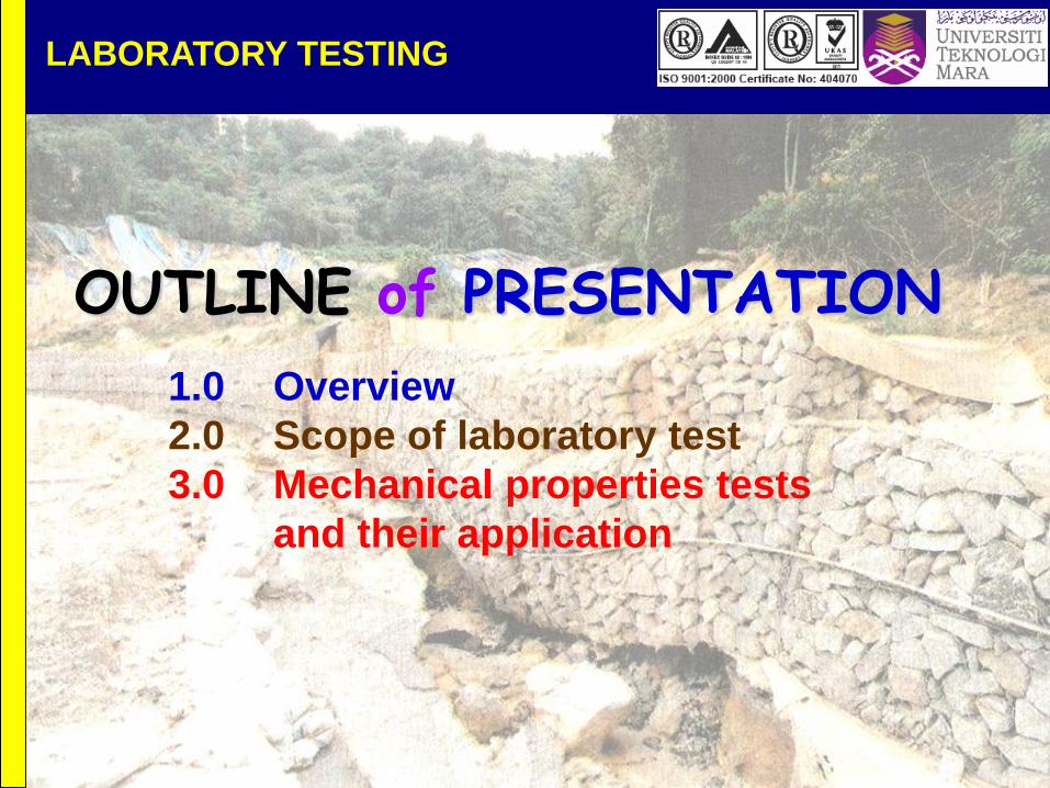
BS Standards BS1377:1990, BS5930:1999
American Standards ASTM
Malaysian Standards MS
Standards for testing
LABORATORY TESTING
BS Standards BS1377:1990, BS5930:1999
Shear Box Test
Triaxial test (UCT, UU, CIU, CID)
Vane Shear test
Compressibility test
Permeability Tests
Find the correct references for each test in the
BS and the equivalent ASTM
Standards for testing
LABORATORY TESTING

3.1 Strength test
3.1.1 Shear Box
3.1.2 Triaxial Test
3.1.3 Vane Shear test
3.2 Compressibility Test
3.3 Permeability Test
3.0 Mechanical Properties of Soils
LABORATORY TESTING

SHEAR STRENGTH OF SOILS
Shear Box Apparatus & Accessories
3.1.1 Shear box
apparatus and
its accessories

SHEAR STRENGTH OF SOILS
Shear box apparatus
Schematic diagram of a shear box apparatus

SHEAR STRENGTH OF SOILS
Data analysis of shear box test

SHEAR STRENGTH OF SOILS
Triaxial sample
SET-UP OF THE
SAMPLES
TESTS AVAILABLE
Unconfined compression
test (UCT)
Unconsolidated undrained
test (UU)
Consolidated isotropically
undrained test (CIU)
Consolidated isotropically
drained test (CID)
3.1.2 Triaxial Test

SHEAR STRENGTH OF SOILS
Interpretation of test results
UNCONFINED COMPRESSION TEST
Is a special case of triaxial
compression, carried out at
zero cell pressure (σ3 = 0).
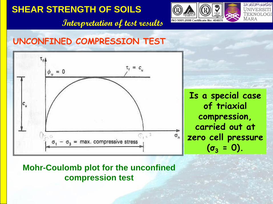
SHEAR STRENGTH OF SOILS
Interpretation of test results
UNCONFINED COMPRESSION TEST
Is a special case of triaxial
compression, carried out at
zero cell pressure (σ3 = 0).
Mohr-Coulomb plot for the unconfined
compression test

SHEAR STRENGTH OF SOILS
Triaxial apparatus and accessories

SHEAR STRENGTH OF SOILS
Diagram of Triaxial cell
THE TRIAXIAL CELL
AND POSITION OF
THE SAMPLE

SHEAR STRENGTH OF SOILS
Interpretation of test results
INTERPRETATION OF TRIAXIAL TEST RESULTS
Strains and stresses in the triaxial test (a) Principal strains
(b) Cell pressure only (c) Stresses at shear failure

SHEAR STRENGTH OF SOILS
Failure modes
(a) Brittle shear
failure (b) Intermediate
shear failure Plastic yielding
failure
MODE OF SHEAR FAILURE IN THE TRIAXIAL TEST

SHEAR STRENGTH OF SOILS
Interpretation of test results
OBTAINING MOHR-COULOMB PARAMETERS
Three specimens of the same soil usually tested at
different cell pressures and a Mohr circle drawn for each
peak or ultimate failure stress. Common tangent drawn as
the strength envelope.

SHEAR STRENGTH OF SOILS
Graphical representation of strength
Comparison of Mohr circles for drained and undrained tests

SHEAR STRENGTH OF SOILS
Graphical representation of strength
Undrained test envelopes for a normally consolidated clay

SHEAR STRENGTH OF SOILS
Graphical representation of strength
Typical example of Mohr circles construction

SHEAR STRENGTH OF SOILS
Graphical representation of strength
ANALYSIS OF SHEAR STRENGTH
DATA TO OBTAIN SHEAR STRENGTH
PARAMETERS USING STRESS PATH
CONCEPT
(a) HALF DIFFERENCE HALF SUM PLOT
(b) SPACE PLOT

SHEAR STRENGTH OF SOILS
Graphical representation of strength
BEFORE WE PROCEED, PLEASE
DEFINE THE FOLLOWING TERMS:
Mohr Circles
Stress Paths
Normally consolidated clay
Overconsolidated clay

SHEAR STRENGTH OF SOILS
Graphical representation of strength
STRESS POINT AND MOHR COULOMB FAILURE ENVELOPES

SHEAR STRENGTH OF SOILS
Graphical representation of strength
(a) STRESS PATHS FOR TRIAXIAL TEST (Half Difference Vs Half Sum
(a) Drained Test

SHEAR STRENGTH OF SOILS
Graphical representation of strength
(b) Consolidated Undrained Test (Normally consolidated clay)
(a) STRESS PATHS FOR TRIAXIAL TEST (Half Difference Vs Half Sum
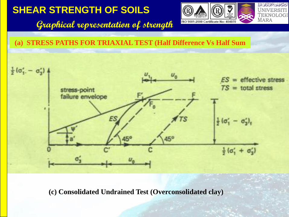
SHEAR STRENGTH OF SOILS
Graphical representation of strength
(c) Consolidated Undrained Test (Overconsolidated clay)
(a) STRESS PATHS FOR TRIAXIAL TEST (Half Difference Vs Half Sum

SHEAR STRENGTH OF SOILS
Graphical representation of strength
(a) STRESS PATHS FOR TRIAXIAL TEST (Half Difference Vs Half Sum)
Correlation between the parameters from Shear strength
envelope and the stress point failure envelope
)'
tan
1- (tan
1-sin
' ' sin
' cos
a'
'c
SHEAR STRENGTH OF SOILS
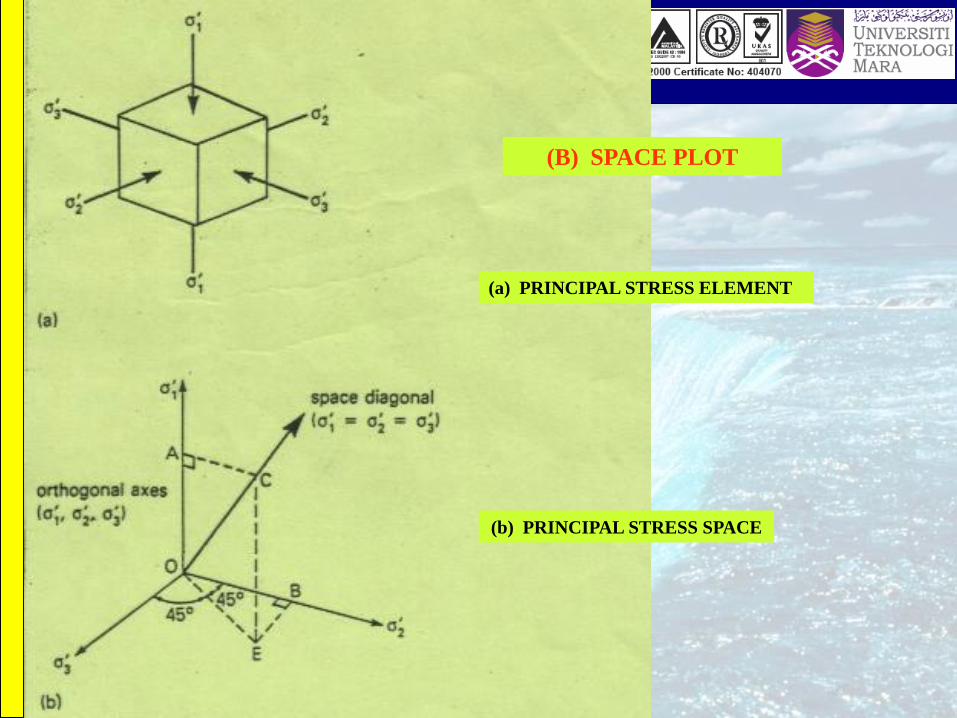
Graphical representation of strength
(a) PRINCIPAL STRESS ELEMENT
(b) PRINCIPAL STRESS SPACE
(B) SPACE PLOT

SHEAR STRENGTH OF SOILS
Graphical representation of strength
STRESS PATH IN PRINCIPAL STRESS
SPACE
(a) Drained test (back pressure = uo)

SHEAR STRENGTH OF SOILS
Graphical representation of strength
STRESS PATH IN PRINCIPAL STRESS
SPACE
(b) Consolidated undrained test

SHEAR STRENGTH OF SOILS
Graphical representation of strength
(b) STRESS PATHS FOR TRIAXIAL TEST (Space Plot)
Correlation between the parameters from Shear
strength envelope and the stress point failure envelope
1 ' 2
1 - ' 2sin '
1 '
1 - '
2
2 ' sin
1-
tan
tan
tan
tan
)' sin -(1 b' 2
1 'c
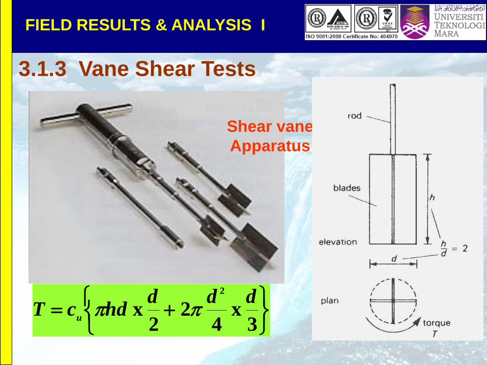
Shear vane
Apparatus
3
x 4
2 2
x 2
dddhdcT
u
FIELD RESULTS & ANALYSIS I
3.1.3 Vane Shear Tests