Embed Size (px)
Citation preview

No. 99MCA084A2SERIES No. 198
QM-Data
QM-Data 300
3D Data Processing Unit
User’s Manual (Operation Guide)
Read this User’s Manual thoroughly before operating the instrument. After reading,
retain it close at hand for future reference.

CONVENTIONS USED IN THIS MANUAL
Safety Precautions To ensure that instruments are operated correctly and safely, Mitutoyo manuals use
safety symbols (Signal Words and Safety Alert Symbols) to identify and warn against hazards and potential accidents.
The following signs indicate general warnings:
DANGER
Indicates an imminently hazardous situation which, if not avoided, will result in serious injuryor death.
WARNING
Indicates a potentially hazardous situation which, if not avoided, could result in serious injuryor death.
CAUTION
Indicates a potentially hazardous situation which, if not avoided, may result in minor ormoderate injury or property damage.
The following signs indicate specific warnings or prohibited actions, or indicate a mandatory action:
Alerts the user to a specific hazardous situation. The given example means “Caution, risk of electric shock”.
Prohibits a specific action. The given example means “Do not disassemble”.
Specifies a required action. The given example means “Ground”.
No. 99MCA084A i

CONVENTIONS USED IN THIS MANUAL
Types of Notes The following types of notes are used in this manual to help the operator obtain
reliable measurement data through correct instrument operation.
IMPORTANT • An important note provides information essential to the completion of a task. You cannot disregard this note to complete the task.
• An important note is a type of precaution, which if neglected could result in a loss of data, decreased accuracy or instrument malfunction/failure.
NOTE A note emphasizes or supplements important points of the main text. It also supplies information about specific situations (e.g., memory limitations, equipment configurations, or details that apply to specific versions of a program).
TIP A tip is a type of note that helps the user apply the techniques and procedures described in the text to his or her specific needs. It also provides reference information associated with the topic being discussed.
Mitutoyo assumes no liability to any party for any loss or damage, direct orindirect, caused by use of this instrument not conforming to this manual.Information in this document is subject to change without notice.
© 2002 Mitutoyo Corporation. All rights reserved.
No. 99MCA084A ii
INTRODUCTION Thank you for choosing the 3D data processing unit “QM-Data”. This manual contains
lessons on basic operations of the “QM-Data”. Effective use of this manual will ensure that you use the “QM-Data” properly and will be helpful during measurement.
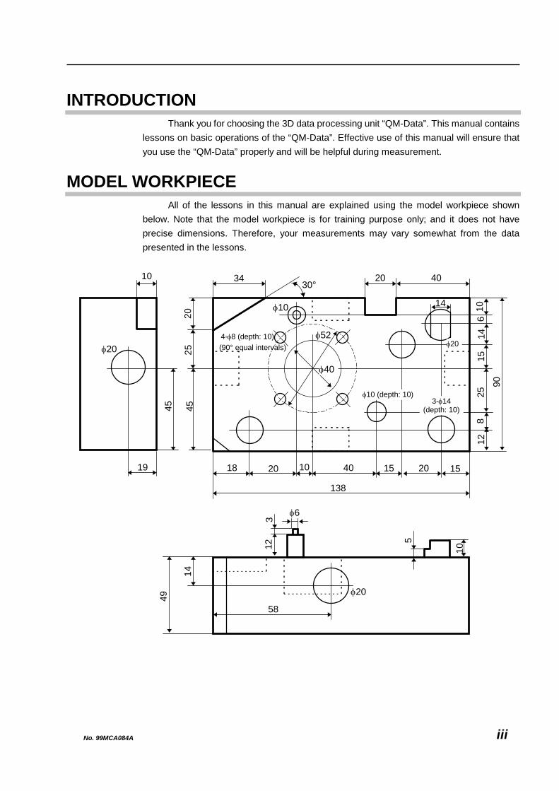
MODEL WORKPIECE All of the lessons in this manual are explained using the model workpiece shown
below. Note that the model workpiece is for training purpose only; and it does not have precise dimensions. Therefore, your measurements may vary somewhat from the data presented in the lessons.
4-φ8 (depth: 10)
58
φ20
φ6
49
14
5
10
312
138
φ52
φ10
φ40
2545
68
1510
1290
25
34
18 15401020
4020
14
30°
20
14
15
20
φ20
45
10
19
(90° equal intervals) φ20
φ10 (depth: 10)3-φ14
(depth: 10)
No. 99MCA084A iii
CONTENTS CONVENTIONS USED IN THIS MANUAL .........................................................................................................i INTRODUCTION ...............................................................................................................................................iii MODEL WORKPIECE.......................................................................................................................................iii 1 BEFORE STARTING MEASUREMENTS .............................................................................................. 1-1
1.1 Overview of Data Processing Unit............................................................................................... 1-1 1.1.1 General Configuration.......................................................................................................... 1-1 1.1.2 Key Panel Configuration...................................................................................................... 1-2 1.1.3 Configuration of LCD Screen .............................................................................................. 1-4 1.1.4 Gage-Like Measurement Screen......................................................................................... 1-5 1.1.5 List of Menu Numbers and Function Numbers ................................................................. 1-6
1.2 Preparing for Measurements........................................................................................................ 1-7 1.2.1 Turning on Power................................................................................................................. 1-7 1.2.2 Defining Absolute Origin ..................................................................................................... 1-8 1.2.3 Calibrating Probe.................................................................................................................. 1-9 1.2.4 Setting Printer Output Mode ON....................................................................................... 1-11
2 BASIC MEASUREMENTS...................................................................................................................... 2-1 2.1 Measuring Height .......................................................................................................................... 2-1
2.1.1 Measuring Height (A) ........................................................................................................... 2-2 2.2 Measuring Width............................................................................................................................ 2-4
2.2.1 Measuring Width of Recess (A)........................................................................................... 2-5 2.2.2 Measuring Width of Projection (B) ..................................................................................... 2-7
2.3 Obtaining Angle Formed by Two Side Planes............................................................................ 2-9 2.3.1 Measuring Side Planes (A) and (B) to Calculate Angle (C)............................................. 2-10
2.4 Measuring Diameter .................................................................................................................... 2-13 2.4.1 Measuring Diameter of Circle (A)...................................................................................... 2-14 2.4.2 Measuring Diameter of Circle (B)...................................................................................... 2-16
2.5 Obtaining Angle Formed by Plane and Cylinder ...................................................................... 2-19 2.5.1 Measuring Plane (A) and Cylinder (B) to Calculate Angle (C)........................................ 2-20
2.6 Obtaining Angle Formed by Two Planes................................................................................... 2-23 2.6.1 Measuring Planes (A) and (B) to Calculate Angle (C) ..................................................... 2-24
2.7 Measuring Center Position of Circle ......................................................................................... 2-26 2.7.1 Measuring Side Planes (A) and (B), then Measuring Circle (C) ..................................... 2-27
2.8 Measuring Center-to-Center Distance of Two Circles ............................................................. 2-31 2.8.1 Obtaining Center-to-Center Distance (C) of Circles (A) and (B) .................................... 2-32
2.9 Inclination Correction ................................................................................................................. 2-34 2.9.1 Measuring Plane (A) to Correct Its Inclination................................................................. 2-35 2.9.2 Measurements Performable after Inclination Correction ............................................... 2-37
3 ALIGNMENT OF PART COORDINATE SYSTEM ................................................................................. 3-1 3.1 Macro Commands for Aligning Coordinate System .................................................................. 3-1
No. 99MCA084A iv

3.1.1 Aligning Part Coordinate System by Coordinate System Alignment Macro No. 1 .........3-2 3.2 General Method for Aligning Coordinate System .......................................................................3-5
3.2.1 Aligning Reference Plane by Measuring Plane (a).............................................................3-6 3.2.2 Aligning Reference Axis by Measuring Side Plane (b) ......................................................3-8 3.2.3 Aligning Origin by Measuring Side Plane (c)....................................................................3-10
4 APPLIED MEASUREMENTS..................................................................................................................4-1 4.1 Performing Tolerance Judgment..................................................................................................4-1
4.1.1 Measuring Diameter of Circle (A) to Perform Tolerance Judgment.................................4-2 4.2 Performing Three-dimensional Measurements...........................................................................4-5
4.2.1 Aligning Part Coordinate System ........................................................................................4-6 4.2.2 Measuring Stepped Cylinder (A) on XY Plane....................................................................4-7 4.2.3 Measuring Master Ball, then Circle (B) on ZX Plane..........................................................4-9
4.3 Performing Other Three-dimensional Measurements ..............................................................4-12 4.3.1 Cylinder diameter measurement........................................................................................4-13 4.3.2 Angle formed by 3 circles...................................................................................................4-13 4.3.3 Circle Formed by Circle Centers........................................................................................4-14 4.3.4 Slotted Hole Measurement .................................................................................................4-14 4.3.5 Rectangular Hole Measurement ........................................................................................4-15 4.3.6 Groove Width Measurement ..............................................................................................4-15 4.3.7 V-groove Measurement ......................................................................................................4-16 4.3.8 Section Circle Measurement (Cone)..................................................................................4-16 4.3.9 Sphere Diameter Measurement .........................................................................................4-17 4.3.10 Cone Angle Measurement ................................................................................................4-17 4.3.11 Cylinder Taper Measurement...........................................................................................4-18 4.3.12 Intersection Angle (2 Cylinders) ......................................................................................4-18 4.3.13 Side Length Measurement ...............................................................................................4-19 4.3.14 Corner Circle Measurement .............................................................................................4-19
4.4 Obtaining Geometrical Deviations .............................................................................................4-20 4.4.1 Obtaining Straightness.......................................................................................................4-21 4.4.2 Obtaining Perpendicularity of Two Planes.......................................................................4-21 4.4.3 Obtaining Perpendicularity of Plane and Cylinder ..........................................................4-22 4.4.4 Obtaining Perpendicularity of Two Cylinders ..................................................................4-23 4.4.5 Obtaining Flatness..............................................................................................................4-23 4.4.6 Obtaining Parallelism of Two Planes ................................................................................4-24 4.4.7 Obtaining Parallelism of Plane and Cylinder....................................................................4-24 4.4.8 Obtaining Parallelism of Two Cylinders ...........................................................................4-25 4.4.9 Obtaining Circularity...........................................................................................................4-25 4.4.10 Obtaining Coaxiality..........................................................................................................4-26 4.4.11 Obtaining Concentricity meas. (2 circles) ......................................................................4-27 4.4.12 Obtaining Runout measurement .....................................................................................4-27
SERVICE NETWORK
No. 99MCA084A v

No. 99MCA084A vi
MEMO

1 BEFORE STARTING MEASUREMENTS This chapter presents lessons on how to prepare the 3D Data Processing Unit QM-Data prior to starting measurement.
1
1.1 Overview of Data Processing Unit 1.1.1 General Configuration
This section describes the names of the major components of the QM-Data.
Display portion (LCD)
Key panel
Fig. 1-1
No. 99MCA084A 1-1

1.1.2 Key Panel Configuration
987F4F3F2F1
F8F7F6F5
F12F11F10F9
654
321
-·0
Function keys
Numeric keys
Suspend key
[CANCEL] key
[ENTER] key
[Back Space] key
Cursor keys
[Delete] key
[Insert] key
[Caps Lock] keyCharacter keys
Fig. 1-2
1) Function keys The function keys are used to select an appropriate function. As shown in Fig. 1-3,
each function key corresponds to an icon provided with that function key number. The function key numbers are F1 to F12.
F1 F2 F3 F4
F5 F6 F7 F8
1
Cartesian coordinateN0123X -23.3260Y 123.5620D 39.8935F 0.1234
Circle measurement
D
F4F3F2F1
F8F7F6F5
F12F11F10F9
Fig. 1-3
No. 99MCA084A 1-2

1. BEFORE STARTING MEASUREMENTS
2) Numeric keys The numeric keys are used to input numerical values such as nominal values.
3) Character keys
The character keys are used to input character strings such as file names.
4) Cursor keys The cursor keys are used to move the cursor.
5) Suspend key
The Suspend key is used to suspend or resume data processing by the QM-Data. When the QM-Data is in the Suspend Mode, the LCD is extinguished and the red LED corresponding to this Suspend key lights.
6) [CANCEL] key
The [CANCEL] key is used to cancel one measurement point or return to the immediately previous menu.
7) [ENTER] key
The [ENTER] key is used to enter a selection or an input to go to the next processing.
8) [Caps Lock] key
The [Caps Lock] key is used to switch the alphabet between uppercase and lowercase.
9) [Back Space] key
The [Back Space] key is used to erase one character positioned before the cursor.
10) [Insert] key The [Insert] key is used to switch the editing mode between the Insert Mode
(inserting characters) and the Replace Mode (overwriting characters).
11) [Delete] key The [Delete] key is used to erase one character where the cursor is positioned.
No. 99MCA084A 1-3
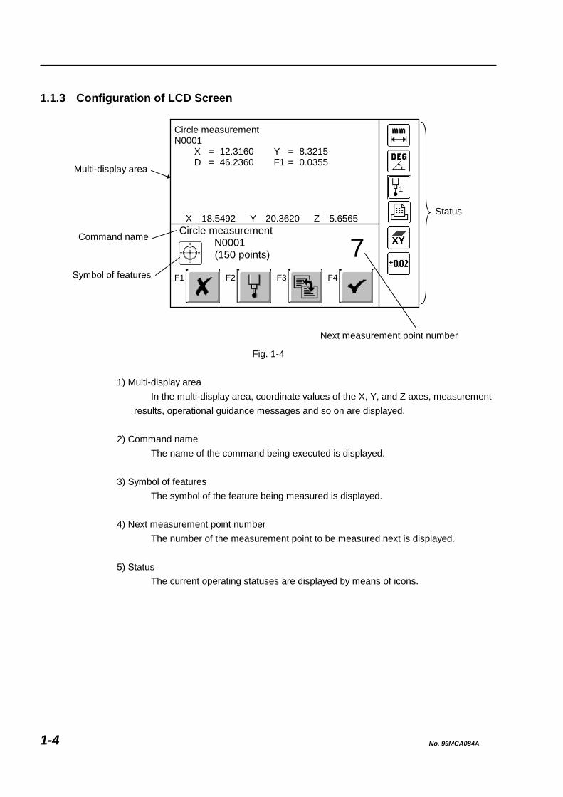
1.1.3 Configuration of LCD Screen
7X 18.5492 Y 20.3620 Z 5.6565
Circle measurementN0001
X = 12.3160 Y = 8.3215D = 46.2360 F1 = 0.0355
Circle measurement N0001
(150 points)
1
F1 F2 F3 F4
Status
Symbol of features
Command name
Multi-display area
Next measurement point number Fig. 1-4
1) Multi-display area
In the multi-display area, coordinate values of the X, Y, and Z axes, measurement results, operational guidance messages and so on are displayed.
2) Command name
The name of the command being executed is displayed.
3) Symbol of features The symbol of the feature being measured is displayed.
4) Next measurement point number
The number of the measurement point to be measured next is displayed.
5) Status The current operating statuses are displayed by means of icons.
No. 99MCA084A 1-4

1. BEFORE STARTING MEASUREMENTS
1.1.4 Gage-Like Measurement Screen
Measurement input wait screen (for example: flatness measurement)
F1: Returns to the gage-like measurement screen. F2: Performs the probe calibration, etc. (For the detailed information, refer to section 2.9 Probe Function for interrupting Measurement in the Software Guide 1) F3: Switches the screen to the measured result screen.
TIP The position where a No. blinks (3 in the screen above) is in measurement input wait status.
<Measured result screen (for example: flatness measurement)>
F1: Performs a re-measurement. F2: Recalls the same processing command again. F3: Performs the statistical processing <QMStat (option)> on the measured data. (For the detailed information, refer to the QMStat Operation Guide (99MCA094). F4: Measurement end (returns to the menu screen.)
No. 99MCA084A 1-5
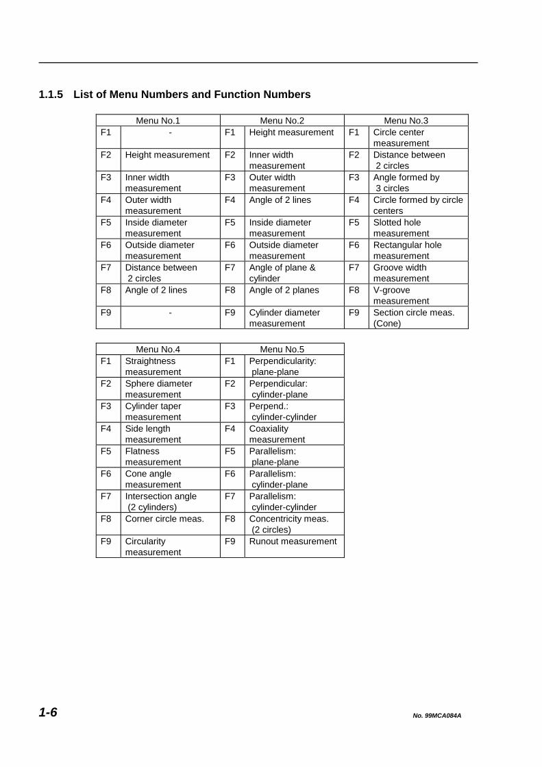
1.1.5 List of Menu Numbers and Function Numbers
Menu No.1 Menu No.2 Menu No.3 F1 - F1 Height measurement F1 Circle center
measurement F2 Height measurement F2 Inner width
measurement F2 Distance between
2 circles F3 Inner width
measurement F3 Outer width
measurement F3 Angle formed by
3 circles F4 Outer width
measurement F4 Angle of 2 lines F4 Circle formed by circle
centers F5 Inside diameter
measurement F5 Inside diameter
measurement F5 Slotted hole
measurement F6 Outside diameter
measurement F6 Outside diameter
measurement F6 Rectangular hole
measurement F7 Distance between
2 circles F7 Angle of plane &
cylinder F7 Groove width
measurement F8 Angle of 2 lines F8 Angle of 2 planes F8 V-groove
measurement F9 - F9 Cylinder diameter
measurement F9 Section circle meas.
(Cone)
Menu No.4 Menu No.5 F1 Straightness
measurement F1 Perpendicularity:
plane-plane F2 Sphere diameter
measurement F2 Perpendicular:
cylinder-plane F3 Cylinder taper
measurement F3 Perpend.:
cylinder-cylinder F4 Side length
measurement F4 Coaxiality
measurement F5 Flatness
measurement F5 Parallelism:
plane-plane F6 Cone angle
measurement F6 Parallelism:
cylinder-plane F7 Intersection angle
(2 cylinders) F7 Parallelism:
cylinder-cylinder F8 Corner circle meas. F8 Concentricity meas.
(2 circles) F9 Circularity
measurement F9 Runout measurement
No. 99MCA084A 1-6

1. BEFORE STARTING MEASUREMENTS
1.2 Preparing for Measurements [Objective of lesson]
To learn the operational procedure for turning on the power and preparing for measurement.
[Operational procedure]
1) Turn on the power of the QM-Data. 2) Define the absolute origin of the CMM (Coordinate Measuring Machine). 3) Calibrate the probe. 4) Turn the printer output mode ON.
NOTE When using the QM-Data along with any CMM that does not have the volumetric error compensation function, turn on the power, then start from Section 1.2.3 “Calibrating Probe”.
1.2.1 Turning on Power
Table 1-1 No. Operational step Screen display or remarks
1 Turn on the power switch. -
2 The startup screen appears. The startup screen shown on the right appears after several seconds.
No. 99MCA084A 1-7

1.2.2 Defining Absolute Origin
IMPORTANT • The absolute origin must be defined every time the system is started up.
• If you perform measurements without having defined the absolute origin, correct measurement results cannot be obtained.
• The position of the absolute origin depends on the model of the CMMs (Coordinate Measuring Machines). Refer to the User’s Manual of the main unit of the CMM for information on the position of the absolute origin.
Table 1-2
No. Operational step Screen display or remarks
1 Moving the probe. If the screen shown on the right appears, move the probe to the middle region of the CMM.
F4F3F2F1
Start the process defining theabsolute origin.Move probe to the middle of CMM.
2 Starting the definition of the absolute origin.
Press the function key corresponding to the icon.
F4F3F2F1
Start the process defining theabsolute origin.Move probe to the middle of CMM.
3 Defining the absolute origin. Move the probe to the position beyond the absolute zero point of the Linear Scale on each axis (X, Y, and Z).
Move the probe to the absoluteorigin.
F4F3F2F1
No. 99MCA084A 1-8
1. BEFORE STARTING MEASUREMENTS
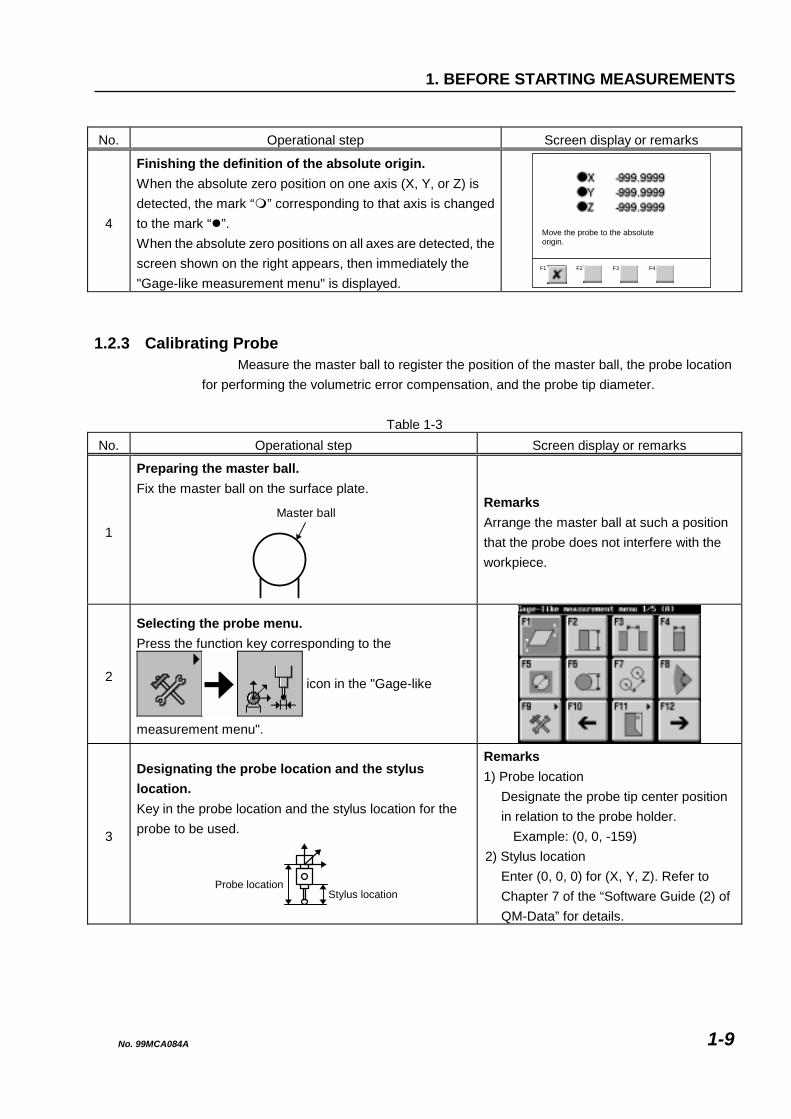
No. Operational step Screen display or remarks
4
Finishing the definition of the absolute origin. When the absolute zero position on one axis (X, Y, or Z) is detected, the mark “ ” corresponding to that axis is changed to the mark “ ”. When the absolute zero positions on all axes are detected, the screen shown on the right appears, then immediately the "Gage-like measurement menu" is displayed.
Move the probe to the absoluteorigin.
F4F3F2F1
1.2.3 Calibrating Probe
Measure the master ball to register the position of the master ball, the probe location for performing the volumetric error compensation, and the probe tip diameter.
Table 1-3
No. Operational step Screen display or remarks
1
Preparing the master ball. Fix the master ball on the surface plate.
Master ball
Remarks Arrange the master ball at such a position that the probe does not interfere with the workpiece.
2
Selecting the probe menu. Press the function key corresponding to the
icon in the "Gage-like
measurement menu".
3
Designating the probe location and the stylus location. Key in the probe location and the stylus location for the probe to be used.
Stylus locationProbe location
Remarks 1) Probe location
Designate the probe tip center position in relation to the probe holder.
Example: (0, 0, -159) 2) Stylus location
Enter (0, 0, 0) for (X, Y, Z). Refer to Chapter 7 of the “Software Guide (2) of QM-Data” for details.
No. 99MCA084A 1-9

No. Operational step Screen display or remarks
4
Measuring the master ball. Perform measurements at five points on the master ball.
(5)
(4)
(3)(2)
(1)
Remarks To accurately measure the master ball, measure the four points (1) to (4) on the horizontal major circumference, then measure the top point (5).
5 Finishing the registration.
Press the function key corresponding to the icon. -
NOTE • Once the probe tip diameter is registered, the registered data of the tip diameter is maintained when the power is turned off.
• The procedure described in this section must be repeated when the arranged position of the master ball is changed or the probe has been replaced with another probe.
TIP When an incorrect point has been measured, press the [CANCEL] key to cancel that measured point. If you keep pressing the [CANCEL] key, you can return to the first point measurement.
No. 99MCA084A 1-10
1. BEFORE STARTING MEASUREMENTS
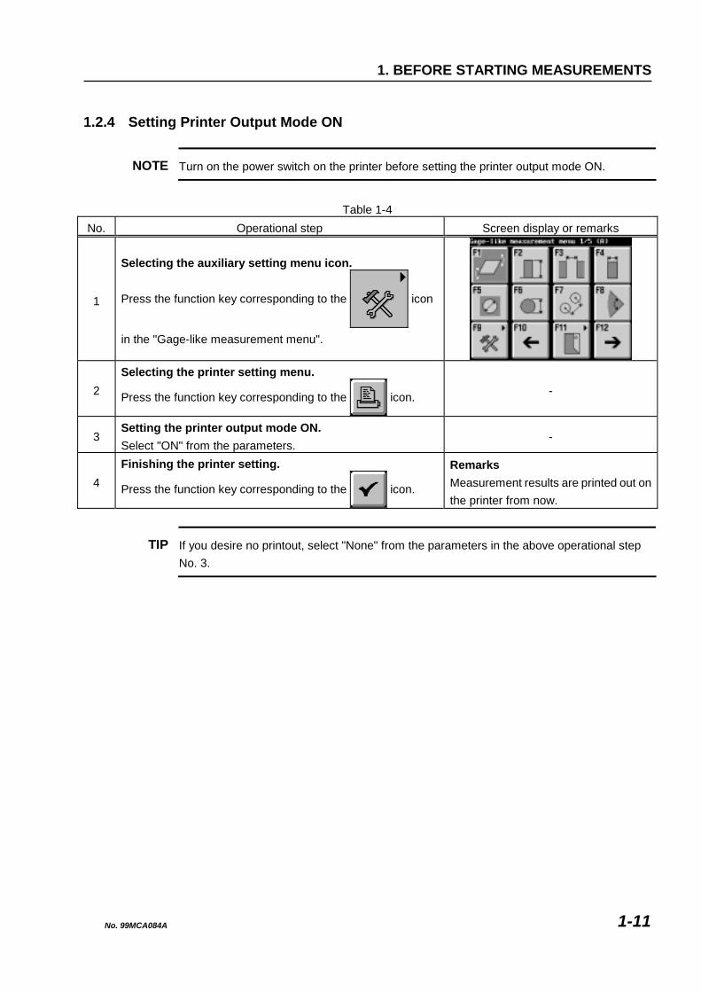
1.2.4 Setting Printer Output Mode ON
NOTE Turn on the power switch on the printer before setting the printer output mode ON.
Table 1-4
No. Operational step Screen display or remarks
1
Selecting the auxiliary setting menu icon.
Press the function key corresponding to the icon
in the "Gage-like measurement menu".
2 Selecting the printer setting menu.
Press the function key corresponding to the icon. -
3 Setting the printer output mode ON. Select "ON" from the parameters.
-
4 Finishing the printer setting.
Press the function key corresponding to the icon.
Remarks Measurement results are printed out on the printer from now.
TIP If you desire no printout, select "None" from the parameters in the above operational step No. 3.
No. 99MCA084A 1-11

No. 99MCA084A 1-12
MEMO
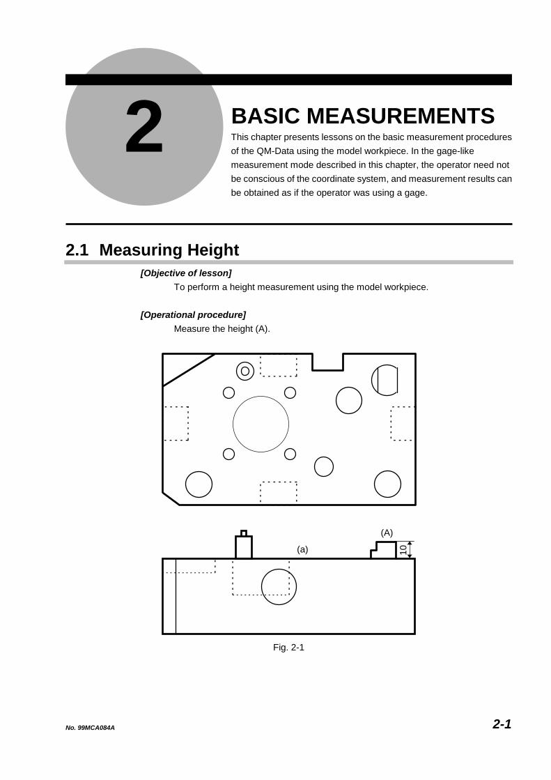
2 BASIC MEASUREMENTS This chapter presents lessons on the basic measurement procedures of the QM-Data using the model workpiece. In the gage-like measurement mode described in this chapter, the operator need not be conscious of the coordinate system, and measurement results can be obtained as if the operator was using a gage.
2
2.1 Measuring Height [Objective of lesson]
To perform a height measurement using the model workpiece.
[Operational procedure] Measure the height (A).
(a)
(A)
10
Fig. 2-1
No. 99MCA084A 2-1

TIP • Prepare the QM-Data and the CMM (Coordinate Measuring Machine) in advance. See Section 1.2 “Preparing for Measurements” for the preparation of the QM-Data.
• Display the "Gage-like measurement menu (2/5)".
2.1.1 Measuring Height (A)
Table 2-1 No. Operational step Screen display or remarks
1
Preparing the workpiece. Set the model workpiece on the surface plate as shown below.
-
2
Starting measurement.
Press the function key corresponding to the icon in the
"Gage-like measurement menu (2/5)".
-
3
Measuring the reference plane. Measure three points on reference plane (a).
(a)
Remarks Perform measurements according to the graphic guidance displayed on the LCD.
(A)
(A)
Probe
No. 99MCA084A 2-2

2. BASIC MEASUREMENTS
No. Operational step Screen display or remarks
4
Moving the probe. Move the probe to position (b).
(b)(a)
Probe
-
5
Measuring the position of the upper plane. Measure one point on upper plane (A).
Probe
(A)
-
6
Moving the probe. Move the probe to position (c).
(c)
Probe
-
7
Measurement result is displayed. Measurement result (SC) of height (A) is displayed on the LCD.
(A)
N0001 SC= 10.0165
No. 99MCA084A 2-3

2.2 Measuring Width [Objective of lesson]
To perform width measurements using the model workpiece.
[Operational procedure] 1) Measure the width of recess (A). 2) Measure the width of projection (B).
(A)
4020
(C) (D) (E)(B)
Fig. 2-2
TIP • Prepare the QM-Data and the CMM (Coordinate Measuring Machine) in advance. See Section 1.2 “Preparing for Measurements” for the preparation of the QM-Data.
• Display the "Gage-like measurement menu (2/5)".
No. 99MCA084A 2-4

2. BASIC MEASUREMENTS
2.2.1 Measuring Width of Recess (A)
Table 2-2 No. Operational step Screen display or remarks
1
Preparing the workpiece. Set the model workpiece on the surface plate as shown below (viewed from the top).
-
2
Starting measurement.
Press the function key corresponding to the icon in the
"Gage-like measurement menu (2/5)".
-
3
Measuring side plane (C). Measure three points on side plane (C) of recess (A).
(C)Probe
12
3
Remarks Perform measurements according to the graphic guidance displayed on the LCD.
4
Moving the probe. Move the probe to position (a).
Probe
(a)
-
(D)(C)(A)
No. 99MCA084A 2-5

No. Operational step Screen display or remarks
5
Measuring side plane (D). Measure one point on side plane (D) of recess (A).
Probe
(D)
-
6
Moving the probe. Move the probe to position (b).
Probe
(b)
(D)
-
7
Measurement result is displayed. Measurement result (SC) of the width of recess (A) is displayed on the LCD.
N0001 SC= 20.0152
(A)
NOTE When measuring a width, make sure to measure three points on the one plane forming the width, then to measure one point on another plane forming the width.
No. 99MCA084A 2-6

2. BASIC MEASUREMENTS
2.2.2 Measuring Width of Projection (B)
Table 2-3 No. Operational step Screen display or remarks
1
Preparing the workpiece. Set the model workpiece on the surface plate as shown below (viewed from the top).
-
2
Starting measurement.
Press the function key corresponding to the icon in the
"Gage-like measurement menu (2/5)".
-
3
Measuring side plane (D). Measure three points on side plane (D) of projection (B).
Probe
(D)1
23
Remarks Perform measurements according to the graphic guidance displayed on the LCD.
4
Moving the probe. Move the probe to position (b).
Probe
(b)
(D)
-
(E)
(D)
(B)
No. 99MCA084A 2-7
No. Operational step Screen display or remarks
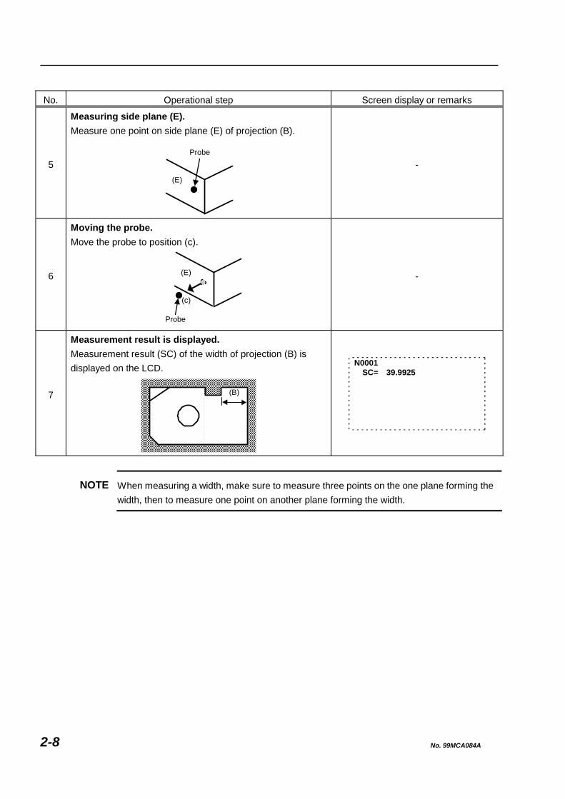
5
Measuring side plane (E). Measure one point on side plane (E) of projection (B).
Probe
(E)
-
6
Moving the probe. Move the probe to position (c).
Probe
(c)
(E)
-
7
Measurement result is displayed. Measurement result (SC) of the width of projection (B) is displayed on the LCD.
N0001 SC= 39.9925
(B)
NOTE When measuring a width, make sure to measure three points on the one plane forming the width, then to measure one point on another plane forming the width.
No. 99MCA084A 2-8

2. BASIC MEASUREMENTS
2.3 Obtaining Angle Formed by Two Side Planes [Objective of lesson]
To obtain the angle formed by two side planes using the model workpiece.
[Operational procedure] Measure the side planes (A) and (B), then calculate the angle (C).
(a)
(A)150°(C)
(B)
Fig. 2-3
TIP • Prepare the QM-Data and the CMM (Coordinate Measuring Machine) in advance. See Section 1.2 “Preparing for Measurements” for the preparation of the QM-Data.
• Display the "Gage-like measurement menu (2/5)".
No. 99MCA084A 2-9

2.3.1 Measuring Side Planes (A) and (B) to Calculate Angle (C)
Table 2-4 No. Operational step Screen display or remarks
1
Preparing the workpiece. Set the model workpiece on the surface plate as shown below (viewed from the top).
-
2
Starting measurement.
Press the function key corresponding to the icon in the
"Gage-like measurement menu (2/5)".
-
3
Measuring the reference plane. Measure three points on reference plane (a).
Probe
(a)
Remarks Perform measurements according to the graphic guidance displayed on the LCD.
(C)
(B)(A)
(C)(A)
(B)
No. 99MCA084A 2-10
2. BASIC MEASUREMENTS
No. Operational step Screen display or remarks
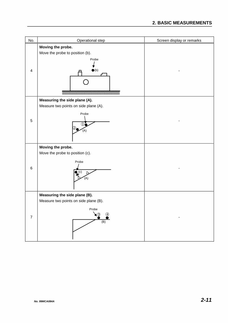
4
Moving the probe. Move the probe to position (b).
(b)
-
5
Measuring the side plane (A). Measure two points on side plane (A).
Probe
(A)
12
-
6
Moving the probe. Move the probe to position (c).
Probe
(A)
(c)
-
7
Measuring the side plane (B). Measure two points on side plane (B).
Probe
(B)
3 4
-
Probe
No. 99MCA084A 2-11

No. Operational step Screen display or remarks
8
Moving the probe. Move the probe to position (d).
Probe
(B)
(d)
-
9
Measurement result is displayed. Measurement result (CA) of angle (C) formed by the two side planes (A) and (B) is displayed on the LCD.
(C)
N0001 CA= 150.0182
NOTE • The obtained angle depends on the measurement sequence of the two side planes as shown below.
Sequence (3)Sequence (2)Sequence (1) Sequence (4)
1
2
34
12
3
4
12
3
4
1
2
34
• The unit of angle can be switched between decimal notation (degree) and sexagesimal notation (degree-minute-second). Refer to Chapter 11 of the “Software Guide (2) of QM-Data” for information on how to switch the angle unit.
No. 99MCA084A 2-12

2. BASIC MEASUREMENTS
2.4 Measuring Diameter [Objective of lesson]
To measure the diameters of circles using the model workpiece.
[Operational procedure] 1) Measure the diameter of circle (A). 2) Measure the diameter of circle (B).
(B)
φ10
(a)
(B)
(A)φ40
Fig. 2-4
TIP • Prepare the QM-Data and the CMM (Coordinate Measuring Machine) in advance. See Section 1.2 “Preparing for Measurements” for the preparation of the QM-Data.
• Display the "Gage-like measurement menu (2/5)".
No. 99MCA084A 2-13
2.4.1 Measuring Diameter of Circle (A)
Table 2-5 No. Operational step Screen display or remarks
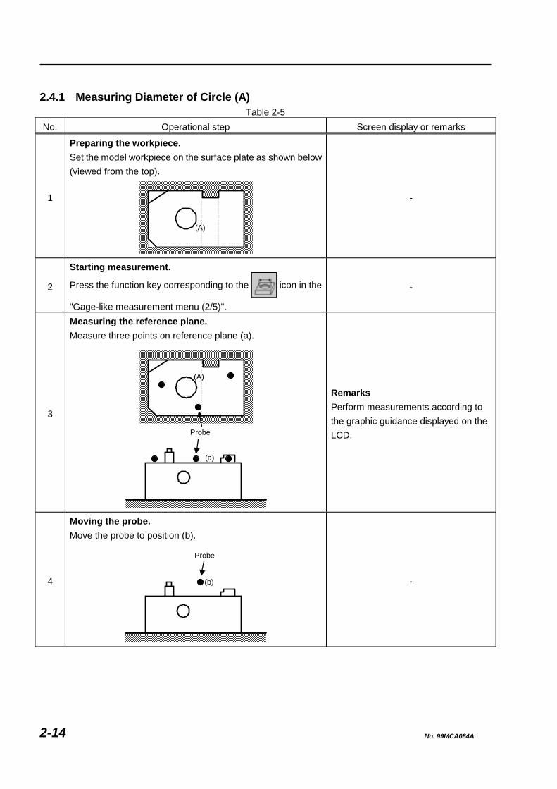
1
Preparing the workpiece. Set the model workpiece on the surface plate as shown below (viewed from the top).
-
2
Starting measurement.
Press the function key corresponding to the icon in the
"Gage-like measurement menu (2/5)".
-
3
Measuring the reference plane. Measure three points on reference plane (a).
(a)
Remarks Perform measurements according to the graphic guidance displayed on the LCD.
4
Moving the probe. Move the probe to position (b).
(b)
-
(A)
(A)
Probe
Probe
No. 99MCA084A 2-14

2. BASIC MEASUREMENTS
No. Operational step Screen display or remarks
5
Measuring the circle (hole). Measure three points on circle (A).
Probe
3
(A)2
1
-
6
Moving the probe. Move the probe to position (c).
Probe
(c)
(A)
-
7
Measurement result is displayed. Measurement result (D1) of diameter (D) of circle (A) is displayed on the LCD.
(A)D
N0001 D1= 40.0823
NOTE • Measure three points on a circle that are fairly evenly spaced to accurately measure the circle.
• After measuring the first point, move the probe toward the center of the hole, then measure the next point. If the probe is moved along the surface of the hole, the probe may touch the workpiece to cause an erroneous input.
• After measuring the last point (third point), make sure to move the probe toward the center of the hole. See the IMPORTANT note in Section 2.4.2 for information on the automatic compensation of the probe tip radius.
No. 99MCA084A 2-15

TIP • When an incorrect point has been measured, press the [CANCEL] key to cancel that measured point. If you keep pressing the [CANCEL] key, you can return to the first point measurement. Note that it is not possible to cancel the last measured point.
• The last measured point cannot be canceled. Therefore, when you have measured the last point at an inappropriate position, re-measure the circle from the beginning.
2.4.2 Measuring Diameter of Circle (B)
Table 2-6 No. Operational step Screen display or remarks
1
Preparing the workpiece. Set the model workpiece on the surface plate as shown below (viewed from the top).
-
2
Starting measurement.
Press the function key corresponding to the icon in the
"Gage-like measurement menu (2/5)".
-
3
Measuring the reference plane. Measure three points on reference plane (a).
Probe
(a)
Remarks Perform measurements according to the graphic guidance displayed on the LCD.
(A)
(B)
(A)
(B)
No. 99MCA084A 2-16
2. BASIC MEASUREMENTS
No. Operational step Screen display or remarks
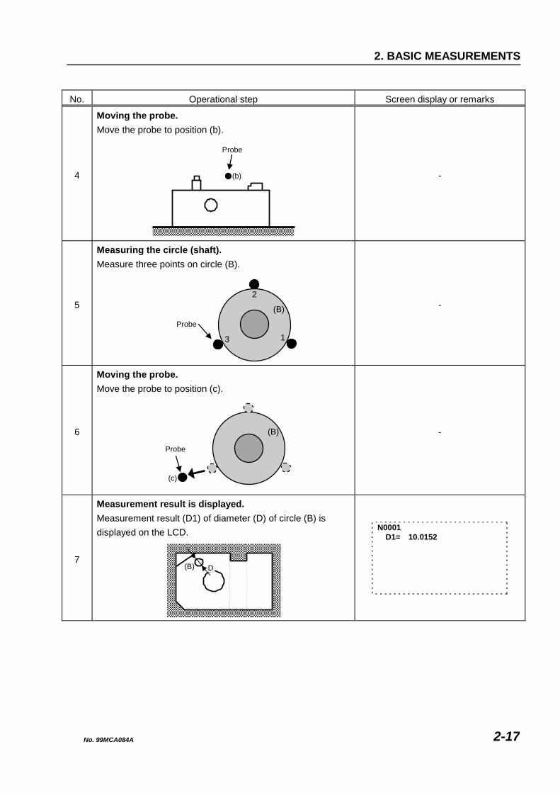
4
Moving the probe. Move the probe to position (b).
(b)
-
5
Measuring the circle (shaft). Measure three points on circle (B).
Probe
3
2
1
(B)
-
6
Moving the probe. Move the probe to position (c).
Probe
(c)
(B)
-
7
Measurement result is displayed. Measurement result (D1) of diameter (D) of circle (B) is displayed on the LCD.
N0001 D1= 10.0152
Probe
D(B)
No. 99MCA084A 2-17

NOTE • Measure three points on a circle that are fairly evenly spaced to accurately measure the circle.
• After having measured the first point, move the probe away from the shaft, then measure the next point. If the probe is moved along the surface of the shaft, the probe may touch the workpiece to cause an erroneous input.
• After measuring the last point (third point), make sure to move the probe away from the shaft.
TIP • When an incorrect point has been measured, press the [CANCEL] key to cancel that measured point. If you keep pressing the [CANCEL] key, you can return to the first point measurement.
• However, it is not possible to cancel the last measured point. Therefore, when you have measured the last point at an inappropriate position, re-measure the circle from the beginning.
IMPORTANT Regarding automatic compensation of probe tip radius:
• With the QM-Data, the probe tip radius is automatically compensated according to the direction in which the probe travels from the last measurement point.
• Example: Cases of hole and shaft
Hole Shaft
2
3 11
2
3
When measuring a hole, move the probe toward the center of the hole. Conversely, when measuring a shaft, move the probe away from the shaft.
No. 99MCA084A 2-18

2. BASIC MEASUREMENTS
2.5 Obtaining Angle Formed by Plane and Cylinder [Objective of lesson]
To obtain the angle formed by the normal line of a plane and the center axis of a cylinder using the model workpiece.
[Operational procedure]
Measure plane (A) and cylinder (B), then calculate angle (C) formed by the normal line of plane (A) and the center axis of cylinder (B).
(C) 0°
(B)(A)
Fig. 2-5
TIP • Prepare the QM-Data and the CMM (Coordinate Measuring Machine) in advance. See Section 1.2 “Preparing for Measurements” for the preparation of the QM-Data.
• Display the "Gage-like measurement menu (2/5)".
No. 99MCA084A 2-19

2.5.1 Measuring Plane (A) and Cylinder (B) to Calculate Angle (C)
Table 2-7 No. Operational step Screen display or remarks
1
Preparing the workpiece. Set the model workpiece on the surface plate as shown below (viewed from the top).
-
2
Starting measurement.
Press the function key corresponding to the icon in the
"Gage-like measurement menu (2/5)".
-
3
Measuring the plane. Measure three points on plane (A).
Probe
(A)
Remarks Perform measurements according to the graphic guidance displayed on the LCD.
(B)
(B)
No. 99MCA084A 2-20

2. BASIC MEASUREMENTS
No. Operational step Screen display or remarks
4
Moving the probe. Move the probe to position (a).
(a)
-
5
Measuring cylinder (B) (first three points). Measure three points on the lower circumferential surface of cylinder (B).
Probe
(B)
123
-
6
Moving the probe. Move the probe to position (b).
Probe
(B)
(b)
-
7
Measuring cylinder (B) (remaining three points). Measure three points on the upper circumferential surface of cylinder (B).
Probe(B)
4
5
6
-
Probe
No. 99MCA084A 2-21

No. Operational step Screen display or remarks
8
Moving the probe. Move the probe to position (c).
Probe(B)
(c)
-
9
Measurement result is displayed. Measurement result (WA) of angle (C) formed by the normal line of plane (A) and the center axis of cylinder (B) is displayed on the LCD.
(C)
N0001 WA= 0.0152
NOTE When measuring a cylinder, make sure to measure the first three points at one level, then to measure the remaining three points at another level.
No. 99MCA084A 2-22
2. BASIC MEASUREMENTS
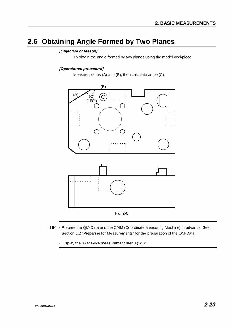
2.6 Obtaining Angle Formed by Two Planes [Objective of lesson]
To obtain the angle formed by two planes using the model workpiece.
[Operational procedure] Measure planes (A) and (B), then calculate angle (C).
(A)(150°)
(C)
(B)
Fig. 2-6
TIP • Prepare the QM-Data and the CMM (Coordinate Measuring Machine) in advance. See Section 1.2 “Preparing for Measurements” for the preparation of the QM-Data.
• Display the "Gage-like measurement menu (2/5)".
No. 99MCA084A 2-23

2.6.1 Measuring Planes (A) and (B) to Calculate Angle (C)
Table 2-8 No. Operational step Screen display or remarks
1
Preparing the workpiece. Set the model workpiece on the surface plate as shown below.
-
2
Starting measurement.
Press the function key corresponding to the icon in the
"Gage-like measurement menu (2/5)".
-
3
Measuring plane (A). Measure three points on the plane (A).
Probe
(A)
12
3
Remarks Perform measurements according to the graphic guidance displayed on the LCD.
4
Moving the probe. Move the probe to position (a).
Probe
(A)(a)
-
(C)
No. 99MCA084A 2-24
2. BASIC MEASUREMENTS
No. Operational step Screen display or remarks
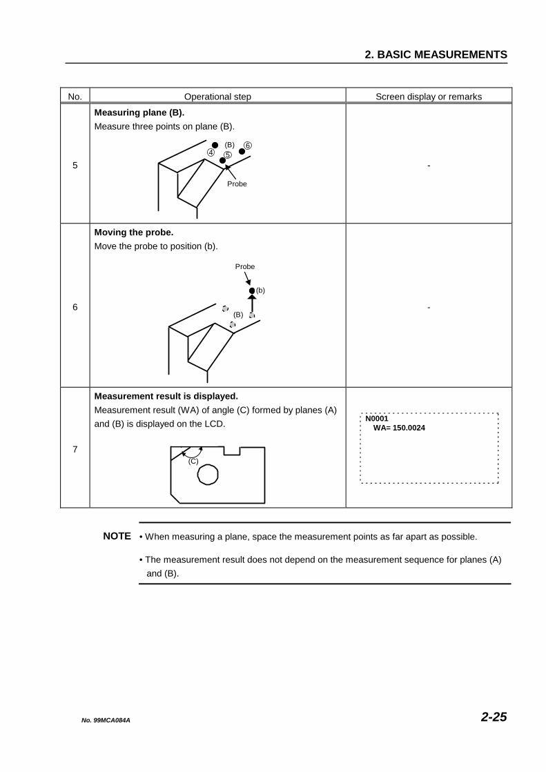
5
Measuring plane (B). Measure three points on plane (B).
Probe
(B)4 5
6
-
6
Moving the probe. Move the probe to position (b).
Probe
(b)
(B)
-
7
Measurement result is displayed. Measurement result (WA) of angle (C) formed by planes (A) and (B) is displayed on the LCD.
(C)
N0001 WA= 150.0024
NOTE • When measuring a plane, space the measurement points as far apart as possible.
• The measurement result does not depend on the measurement sequence for planes (A) and (B).
No. 99MCA084A 2-25

2.7 Measuring Center Position of Circle [Objective of lesson]
To obtain the center position of a hole using the model workpiece. That center position is the position from the lower left corner of the model workpiece when viewed from the top.
[Operational procedure]
Measure side planes (A) and (B), then measure the center position of hole (C).
(a)
(C)
(A)
φ40
(B)
45
48
Fig. 2-7
TIP • Prepare the QM-Data and the CMM (Coordinate Measuring Machine) in advance. See Section 1.2 “Preparing for Measurements” for the preparation of the QM-Data.
• Display the "Gage-like measurement menu (3/5)".
No. 99MCA084A 2-26
2. BASIC MEASUREMENTS
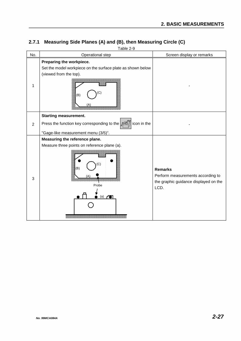
2.7.1 Measuring Side Planes (A) and (B), then Measuring Circle (C)
Table 2-9 No. Operational step Screen display or remarks
1
Preparing the workpiece. Set the model workpiece on the surface plate as shown below (viewed from the top).
-
2
Starting measurement.
Press the function key corresponding to the icon in the
"Gage-like measurement menu (3/5)".
-
3
Measuring the reference plane. Measure three points on reference plane (a).
Probe
(a)
Remarks Perform measurements according to the graphic guidance displayed on the LCD.
(A)
(B)(C)
(A)
(B)(C)
No. 99MCA084A 2-27

No. Operational step Screen display or remarks
4
Moving the probe. Move the probe to position (b).
(b)
-
5
Measuring side plane (A). Measure two points on side plane (A).
Probe
(A)
(B)(C)
-
6
Moving the probe. Move the probe to position (c).
Probe(c)
(A)
(B) (C)
-
7
Measuring side plane (B). Measure one point on side plane (B).
Probe
(A)
(B)(C)
-
Probe
No. 99MCA084A 2-28
2. BASIC MEASUREMENTS
No. Operational step Screen display or remarks
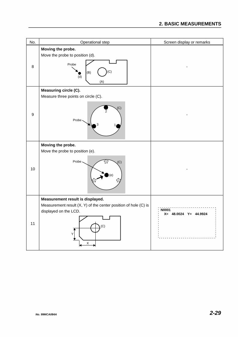
8
Moving the probe. Move the probe to position (d).
Probe
(d)(A)
(B) (C)
-
9
Measuring circle (C). Measure three points on circle (C).
Probe3
(C)2
1
-
10
Moving the probe. Move the probe to position (e).
Probe
(e)
(C)
-
11
Measurement result is displayed. Measurement result (X, Y) of the center position of hole (C) is displayed on the LCD.
(C)
Y
X
N0001 X= 48.0024 Y= 44.9924
No. 99MCA084A 2-29
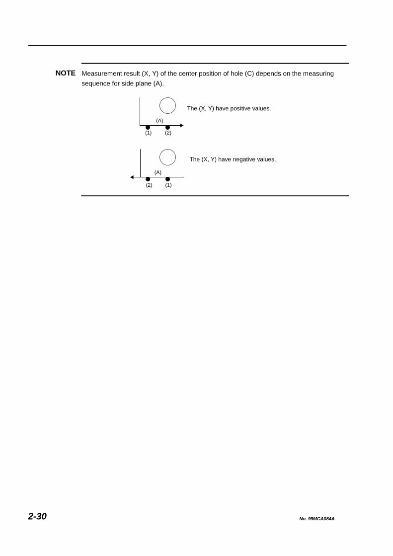
NOTE Measurement result (X, Y) of the center position of hole (C) depends on the measuring sequence for side plane (A).
The (X, Y) have positive values.
The (X, Y) have negative values.
(A)
(1)(2)
(A)
(2)(1)
No. 99MCA084A 2-30
2. BASIC MEASUREMENTS
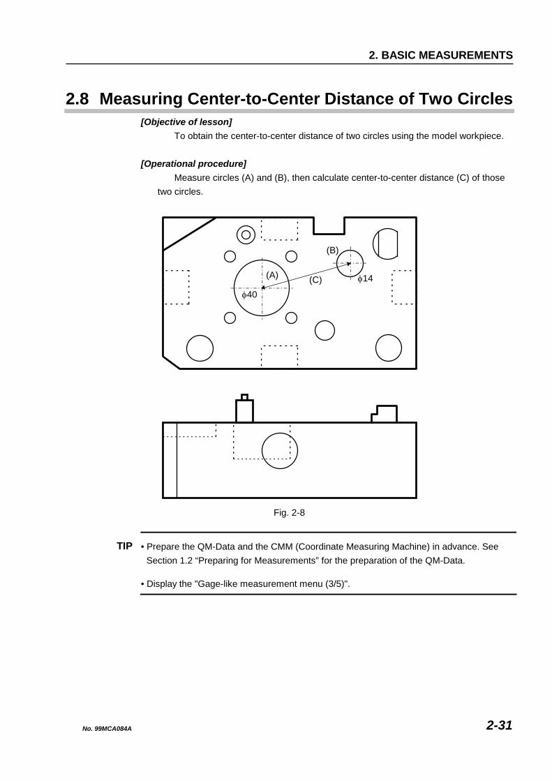
2.8 Measuring Center-to-Center Distance of Two Circles [Objective of lesson]
To obtain the center-to-center distance of two circles using the model workpiece.
[Operational procedure] Measure circles (A) and (B), then calculate center-to-center distance (C) of those
two circles.
(B)
(A) (C) φ14
φ40
Fig. 2-8
TIP • Prepare the QM-Data and the CMM (Coordinate Measuring Machine) in advance. See Section 1.2 “Preparing for Measurements” for the preparation of the QM-Data.
• Display the "Gage-like measurement menu (3/5)".
No. 99MCA084A 2-31
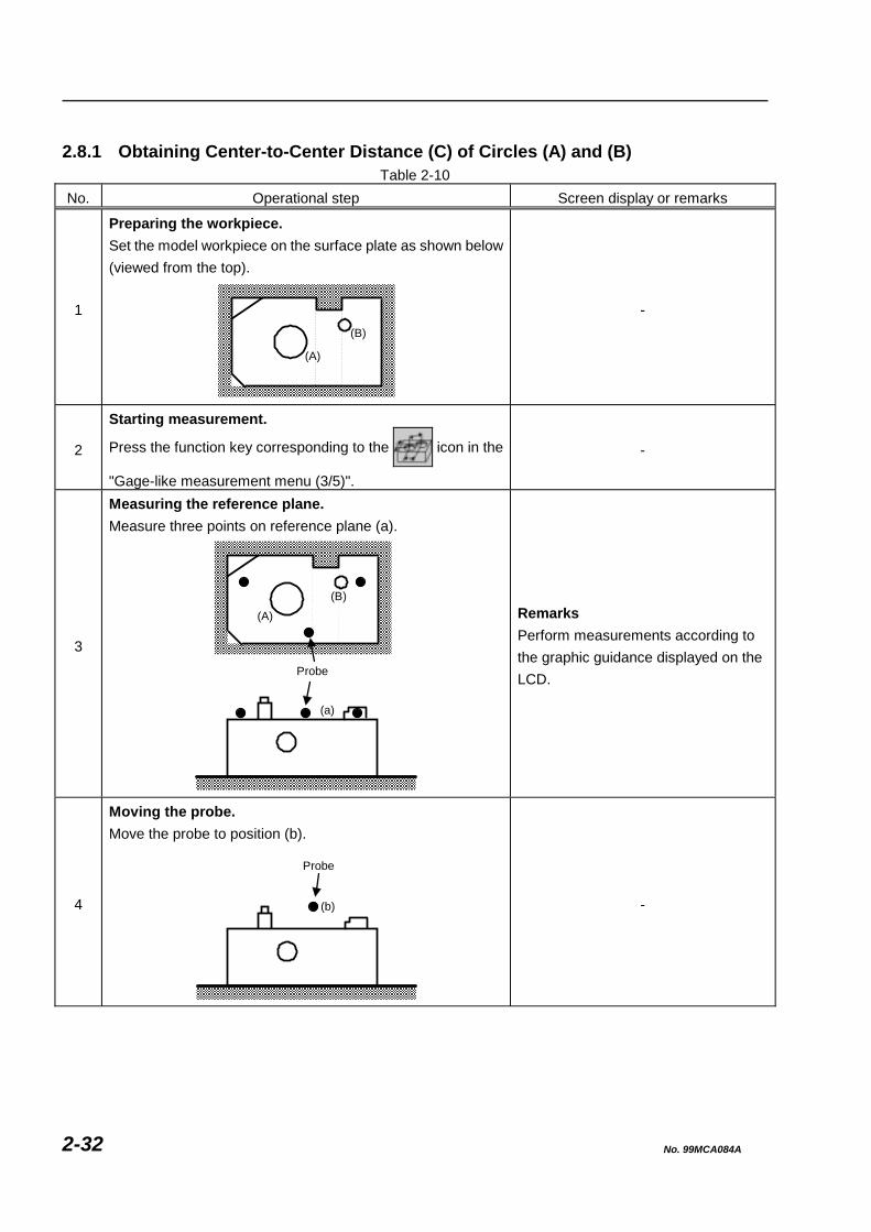
2.8.1 Obtaining Center-to-Center Distance (C) of Circles (A) and (B)
Table 2-10 No. Operational step Screen display or remarks
1
Preparing the workpiece. Set the model workpiece on the surface plate as shown below (viewed from the top).
-
2
Starting measurement.
Press the function key corresponding to the icon in the
"Gage-like measurement menu (3/5)".
-
3
Measuring the reference plane. Measure three points on reference plane (a).
Probe
(a)
Remarks Perform measurements according to the graphic guidance displayed on the LCD.
4
Moving the probe. Move the probe to position (b).
(b)
-
(A)
(B)
(A)
(B)
Probe
No. 99MCA084A 2-32
2. BASIC MEASUREMENTS
No. Operational step Screen display or remarks
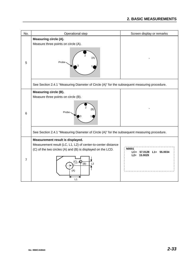
Measuring circle (A). Measure three points on circle (A).
Probe3
(A)2
1
- 5
See Section 2.4.1 “Measuring Diameter of Circle (A)” for the subsequent measuring procedure.
Measuring circle (B). Measure three points on circle (B).
Probe3
2
1
(B)
- 6
See Section 2.4.1 “Measuring Diameter of Circle (A)” for the subsequent measuring procedure.
7
Measurement result is displayed. Measurement result (LC, L1, L2) of center-to-center distance (C) of the two circles (A) and (B) is displayed on the LCD.
(C)(B)
(A)
L2
L1
N0001 LC= 57.0128 L1= 55.0034 L2= 15.0029
No. 99MCA084A 2-33
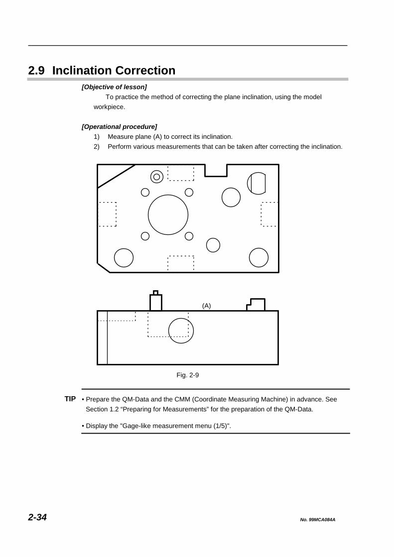
2.9 Inclination Correction [Objective of lesson]
To practice the method of correcting the plane inclination, using the model workpiece.
[Operational procedure]
1) Measure plane (A) to correct its inclination. 2) Perform various measurements that can be taken after correcting the inclination.
(A)
Fig. 2-9
TIP • Prepare the QM-Data and the CMM (Coordinate Measuring Machine) in advance. See Section 1.2 “Preparing for Measurements” for the preparation of the QM-Data.
• Display the "Gage-like measurement menu (1/5)".
No. 99MCA084A 2-34

2. BASIC MEASUREMENTS
IMPORTANT • To use the measurement functions other than those described in Sections 2.1 to 2.8, the “Inclination correction” must be performed in advance.
• The reference plane must be defined to obtain correct measurement results. The “Inclination correction” corresponds to defining the reference plane.
2.9.1 Measuring Plane (A) to Correct Its Inclination
Table 2-11 No. Operational step Screen display or remarks
1
Preparing the workpiece. Set the model workpiece on the surface plate as shown below (viewed from the top).
-
2
Starting the inclination correction.
Press the function key corresponding to the icon in the
"Gage-like measurement menu (1/5)".
-
3
Measuring the reference plane. Measure three points on reference plane (A).
Probe
(A)
Remarks Perform measurements according to the graphic guidance displayed on the LCD.
No. 99MCA084A 2-35

No. Operational step Screen display or remarks
4
Moving the probe. Move the probe to position (a).
(a)
-
5 Completion of inclination correction. Plane (A) is defined as the reference plane. All subsequent measurements are performed based on this reference plane.
-
Probe
No. 99MCA084A 2-36

2. BASIC MEASUREMENTS
2.9.2 Measurements Performable after Inclination Correction
The following measurement functions can be used after the “Inclination correction” has been performed as described in Section 2.9.1, and can be selected from the "Gage-like measurement menu (1/5)".
Table 2-12
No. Name & Function Icon Measurement procedure
1 Height measurement Obtaining a height.
2 Inner width measurement Obtaining the distance between two inward facing planes.
3 Outer width measurement Obtaining the distance between two outward facing planes.
4 Inside diameter measurement Obtaining the diameter of a circle (hole).
5 Outside diameter measurement Obtaining the diameter of a circle (shaft).
6 Measurement of the distance between two circles Obtaining the center-to-center distance (or pitch) of two circles.
1 23
4 56
7 Measurement of the intersecting angle of two side planes Obtaining the intersecting angle of two side planes.
1
2
1
23
1
23
1 2
3
1 2
3
1
2
3
4
No. 99MCA084A 2-37

No. 99MCA084A 2-38
MEMO

3 ALIGNMENT OF PART COORDINATE SYSTEM This chapter presents lessons on aligning the part coordinate system (PCS) using the model workpiece. The part coordinate system forms the basis for evaluating dimensions of a workpiece.
3
3.1 Macro Commands for Aligning Coordinate System [Objective of lesson]
To align the part coordinate system (PCS) according to the No. 1 pattern in the macro commands for aligning the coordinate system, using the model workpiece.
[Operational procedure] Align the part coordinate system by using the No. 1 pattern in the coordinate system
alignment macros. In the No. 1 pattern, the reference plane is aligned by measuring plane (a), then the reference axis is aligned by measuring side plane (b), and finally the origin is aligned by measuring side plane (c).
Y
X
(c)
(b)
Z
Y
(a)Z X
Fig. 3-1
No. 99MCA084A 3-1
TIP • Prepare the QM-Data and the CMM (Coordinate Measuring Machine) in advance. See Section 1.2 “Preparing for Measurements” for the preparation of the QM-Data.
• Display the "Gage-like measurement menu (1/5)".
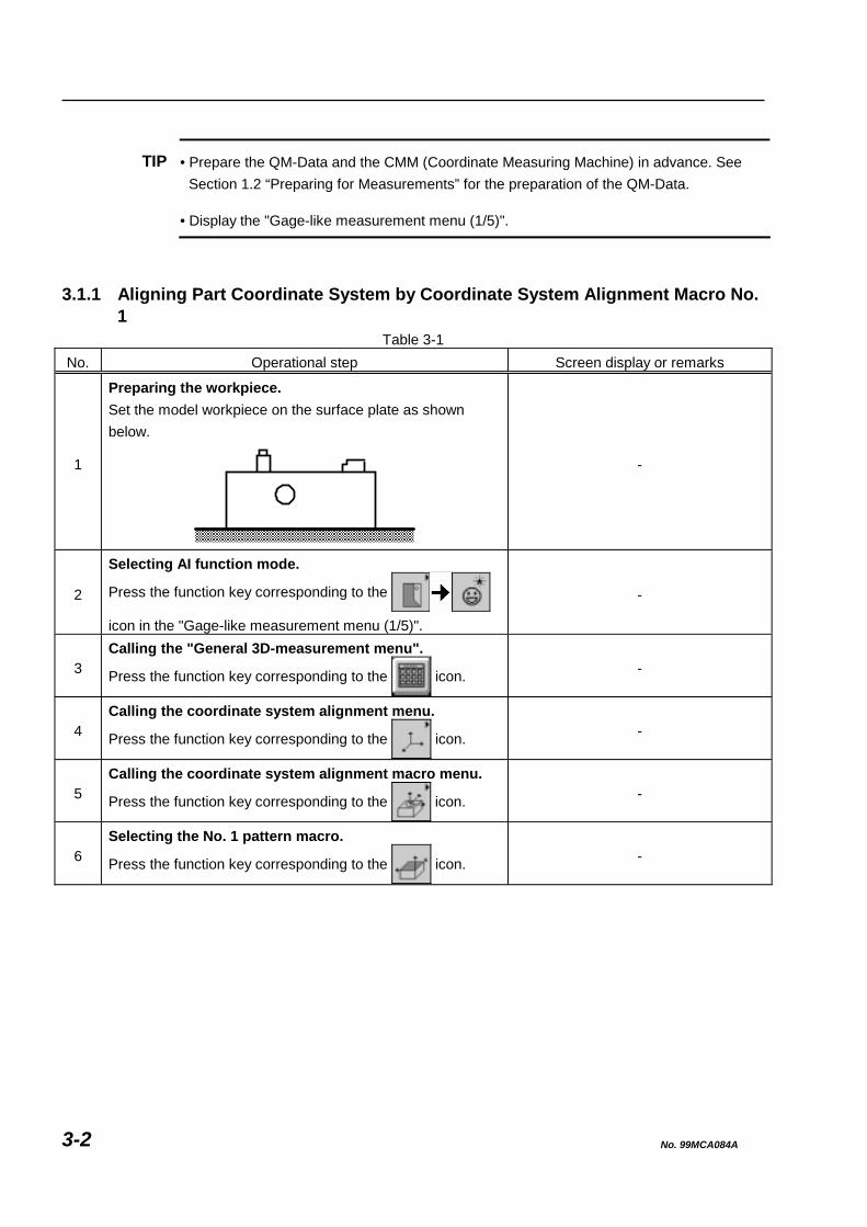
3.1.1 Aligning Part Coordinate System by Coordinate System Alignment Macro No.
1 Table 3-1
No. Operational step Screen display or remarks
1
Preparing the workpiece. Set the model workpiece on the surface plate as shown below.
-
2
Selecting AI function mode.
Press the function key corresponding to the
icon in the "Gage-like measurement menu (1/5)".
-
3 Calling the "General 3D-measurement menu".
Press the function key corresponding to the icon. -
4 Calling the coordinate system alignment menu.
Press the function key corresponding to the icon. -
5 Calling the coordinate system alignment macro menu.
Press the function key corresponding to the icon. -
6 Selecting the No. 1 pattern macro.
Press the function key corresponding to the icon. -
No. 99MCA084A 3-2

3. ALIGNMENT OF PART COORDINATE SYSTEM
No. Operational step Screen display or remarks
7
Measuring plane (a). Measure four points on plane (a).
Probe
(a)
Remarks Perform measurements according to the guidance displayed on the LCD.
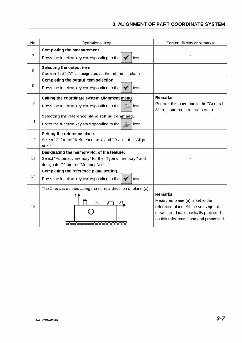
8
The Z axis is defined along the normal direction of plane (a).Z
(X)(a)
Remarks Measured plane (a) is set to the reference plane. All the subsequent measured data is basically projected on this reference plane and processed.
9
Measuring side plane (b). Measure two points on side plane (b).
Probe
(b)
-
10
The reference axis is established. The X axis is defined along side plane (b).
(Y)
X(b)
-
No. 99MCA084A 3-3
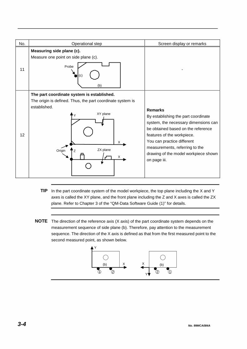
No. Operational step Screen display or remarks
11
Measuring side plane (c). Measure one point on side plane (c).
(b)
(c)
Probe
-
12
The part coordinate system is established. The origin is defined. Thus, the part coordinate system is established.
XY plane
Origin ZX plane
Y
X
Z
X
Remarks By establishing the part coordinate system, the necessary dimensions can be obtained based on the reference features of the workpiece. You can practice different measurements, referring to the drawing of the model workpiece shown on page iii.
TIP In the part coordinate system of the model workpiece, the top plane including the X and Y axes is called the XY plane, and the front plane including the Z and X axes is called the ZX plane. Refer to Chapter 3 of the “QM-Data Software Guide (1)” for details.
NOTE The direction of the reference axis (X axis) of the part coordinate system depends on the measurement sequence of side plane (b). Therefore, pay attention to the measurement sequence. The direction of the X axis is defined as that from the first measured point to the second measured point, as shown below.
(b)
Y
X
1 2
(b)
Y
X
2 1
No. 99MCA084A 3-4

3. ALIGNMENT OF PART COORDINATE SYSTEM
3.2 General Method for Aligning Coordinate System [Objective of lesson]
To align the part coordinate system (PCS) according to the general method for aligning the coordinate system, using the model workpiece.
[Operational procedure] 1) Align or define the reference plane by measuring plane (a). 2) Align or define the reference axis by measuring side plane (b). 3) Align or define the origin by measuring side plane (c).
Y
X
(c)
(b)
Z
Y
(a)Z X
Fig. 3-2
No. 99MCA084A 3-5
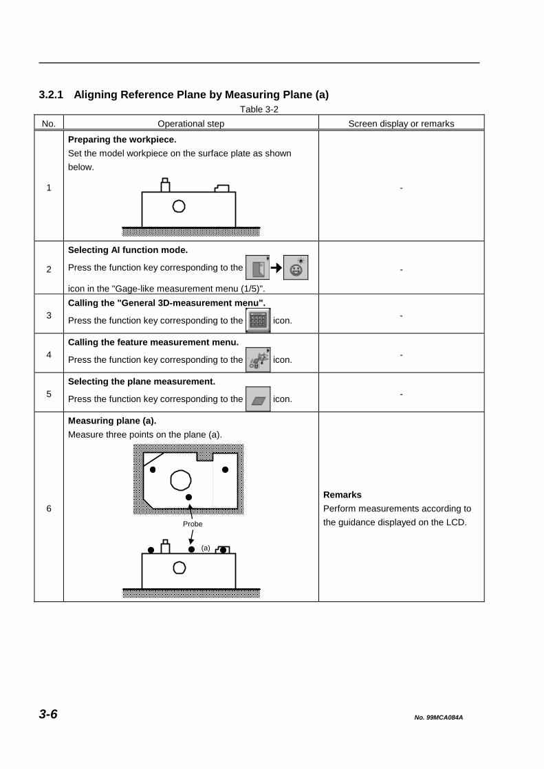
3.2.1 Aligning Reference Plane by Measuring Plane (a)
Table 3-2 No. Operational step Screen display or remarks
1
Preparing the workpiece. Set the model workpiece on the surface plate as shown below.
-
2
Selecting AI function mode.
Press the function key corresponding to the
icon in the "Gage-like measurement menu (1/5)".
-
3 Calling the "General 3D-measurement menu".
Press the function key corresponding to the icon. -
4 Calling the feature measurement menu.
Press the function key corresponding to the icon. -
5 Selecting the plane measurement.
Press the function key corresponding to the icon. -
6
Measuring plane (a). Measure three points on the plane (a).
Probe
(a)
Remarks Perform measurements according to the guidance displayed on the LCD.
No. 99MCA084A 3-6
3. ALIGNMENT OF PART COORDINATE SYSTEM
No. Operational step Screen display or remarks
7 Completing the measurement.
Press the function key corresponding to the icon. -
8 Selecting the output item. Confirm that "XY" is designated as the reference plane.
-
9 Completing the output item selection.
Press the function key corresponding to the icon. -
10 Calling the coordinate system alignment menu.
Press the function key corresponding to the icon.
Remarks Perform this operation in the "General 3D-measurement menu" screen.
11 Selecting the reference plane setting command.
Press the function key corresponding to the icon. -
12 Setting the reference plane. Select "Z" for the "Reference axis" and "ON" for the "Align origin".
-
13 Designating the memory No. of the feature. Select "Automatic memory" for the "Type of memory " and designate "1" for the "Memory No.".
-
14 Completing the reference plane setting.
Press the function key corresponding to the icon. -
15
The Z axis is defined along the normal direction of plane (a).
Remarks Measured plane (a) is set to the reference plane. All the subsequent measured data is basically projected on this reference plane and processed.
Z
(X)(a)
No. 99MCA084A 3-7

3.2.2 Aligning Reference Axis by Measuring Side Plane (b)
Table 3-3 No. Operational step Screen display or remarks
1 Calling the feature measurement menu.
Press the function key corresponding to the icon. -
2 Selecting the straight line measurement.
Press the function key corresponding to the icon. -
3
Measuring side plane (b). Measure two points on the side plane (b).
Probe
(b)
Remarks Perform measurements according to the guidance displayed on the LCD.
4 Completing the measurement.
Press the function key corresponding to the icon. -
5 Selecting the output item. Confirm that "XY" is designated as the reference plane.
-
6 Completing the output item selection.
Press the function key corresponding to the icon. -
7 Calling the coordinate system alignment menu.
Press the function key corresponding to the icon.
Remarks Perform this operation in the "General 3D-measurement menu" screen.
8 Selecting the reference axis setting command.
Press the function key corresponding to the icon. -
No. 99MCA084A 3-8

3. ALIGNMENT OF PART COORDINATE SYSTEM
No. Operational step Screen display or remarks
9 Setting the reference axis. Select "X" for the "Reference axis" and "ON" for the "Align origin".
-
10 Designating the memory No. of the feature. Select "Automatic memory" for the "Type of memory" and designate "1" for the "Memory No.".
-
11 Completing the reference axis setting.
Press the function key corresponding to the icon. -
12
The reference axis is established. The X axis is defined along side plane (b).
(Y)
X(b)
-
No. 99MCA084A 3-9

3.2.3 Aligning Origin by Measuring Side Plane (c)
Table 3-4 No. Operational step Screen display or remarks
1 Calling the feature measurement menu.
Press the function key corresponding to the icon. -
2 Selecting the side point measurement.
Press the function key corresponding to the icon. -
3
Measuring side plane (c). Measure one point on side plane (c).
(b)
(c)
Probe
Remarks Perform measurements according to the guidance displayed on the LCD.
4 Completing the measurement.
Press the function key corresponding to the icon. -
5 Selecting the output item. Confirm that "XY" is designated as the reference plane.
-
6 Completing the output item selection.
Press the function key corresponding to the icon. -
7 Calling the coordinate system alignment menu.
Press the function key corresponding to the icon.
Remarks Perform this operation in the "General 3D-measurement menu" screen.
8 Selecting the origin setting command.
Press the function key corresponding to the icon. -
9 Setting the origin. Set "Translation" only for the X axis in the "Origin align. axis" (axes along which the origin should be translated).
-
No. 99MCA084A 3-10
3. ALIGNMENT OF PART COORDINATE SYSTEM
No. Operational step Screen display or remarks
10 Designating the memory No. of the feature. Select "Automatic memory" for the "Type of memory" and designate "1" for the "Memory No.".
-
11 Completing the origin setting.
Press the function key corresponding to the icon. -
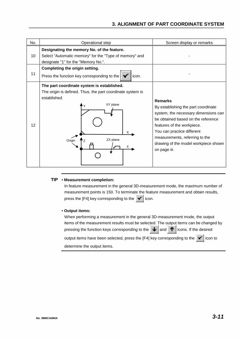
12
The part coordinate system is established. The origin is defined. Thus, the part coordinate system is established.
XY plane
Origin ZX plane
Y
X
Z
X
Remarks By establishing the part coordinate system, the necessary dimensions can be obtained based on the reference features of the workpiece. You can practice different measurements, referring to the drawing of the model workpiece shown on page iii.
TIP • Measurement completion: In feature measurement in the general 3D-measurement mode, the maximum number of measurement points is 150. To terminate the feature measurement and obtain results, press the [F4] key corresponding to the icon.
• Output items: When performing a measurement in the general 3D-measurement mode, the output items of the measurement results must be selected. The output items can be changed by pressing the function keys corresponding to the and icons. If the desired
output items have been selected, press the [F4] key corresponding to the icon to
determine the output items.
No. 99MCA084A 3-11

No. 99MCA084A 3-12
MEMO

4 APPLIED MEASUREMENTS This chapter presents lessons on the applied measurement procedures of the QM-Data using the model workpiece.
4
4.1 Performing Tolerance Judgment [Objective of lesson]
To compare a measurement result with a nominal value.
[Operational procedure] Measure the diameter of circle (A), then compare the measurement result with the
tolerance zone.
(A)
+0.1-0.1φ40
+0.1
-0.1
45
+0.1-0.148
Fig. 4-1
No. 99MCA084A 4-1

TIP • Prepare the QM-Data and the CMM (Coordinate Measuring Machine) in advance. See Section 1.2 “Preparing for Measurements” for the preparation of the QM-Data.
• Display the "Gage-like measurement menu (1/5)".
NOTE See Chapter 3 “Alignment of Part Coordinate System” for information on the method of aligning or establishing the part coordinate system.
4.1.1 Measuring Diameter of Circle (A) to Perform Tolerance Judgment
Table 4-1 No. Operational step Screen display or remarks
1
Preparing the workpiece. Set the model workpiece on the surface plate as shown below (viewed from the top).
-
2 Aligning the part coordinate system. Align or establish the part coordinate system referring to Chapter 3 “Alignment of Part Coordinate System”.
3
Selecting AI function mode.
Press the function key corresponding to the
icon in the "Gage-like measurement menu (1/5)".
-
4 Calling the "General 3D-measurement menu ".
Press the function key corresponding to the icon. -
5 Calling the feature measurement menu.
Press the function key corresponding to the icon. -
(A)
No. 99MCA084A 4-2

4. APPLIED MEASUREMENTS
No. Operational step Screen display or remarks
6
Selecting the circle measurement.
Press the function key corresponding to the
icon.
-
Measuring circle (A). Measure three points on circle (A).
Probe3
(A)2
1
Remarks Perform measurements according to the guidance displayed on the LCD. 7
See Section 2.4.1 “Measuring Diameter of Circle (A)” for the subsequent measuring procedure.
8
Completing the measurement.
Press the function key corresponding to the
icon.
-
9 Selecting the output item. Select "Cartesian coord.".
-
10
Starting Tolerance Judgment.
Press the function key corresponding to the
icon.
Remarks Each time the icon shown on the left is selected, the current tolerance judgment state is switched between ON and OFF. The current tolerance judgment state can be confirmed by checking whether or not the icon shown in the right portion of the LCD is shaded:
(ON) (OFF)
11
Completing the output item selection.
Press the function key corresponding to the
icon.
-
No. 99MCA084A 4-3

No. Operational step Screen display or remarks
12
Inputting tolerance judgment conditions. Move the cursor by the cursor keys to the column where a nominal value should be input, then key in a nominal value, an upper tolerance, and a lower tolerance by the numeric keys. Note that tolerance judgment is not performed for the items that do not have any input data.
Item Nominal U. tol. L. tol.Coord. X 48.0000 0.1000 -0.1000Coord. Y 45.0000 0.1000 -0.1000Diameter D 40.0000 0.1000 -0.1000
13
Establishing the tolerance judgment conditions.
Press the function key corresponding to the
icon.
-
14
Displaying the tolerance judgment results. The actual center position (X, Y) and diameter (D1) of circle (A) can be judged to be good or not good.
(A)Y
X
D
============================Actual NominalDev. U. tol. L. tol.
============================Circle measurementN0001
X= 48.0024 48.0000.0024 0.100 - 0.100
Y= 44.9924 45.000- 0.0076 0.100 - 0.100
D1= 40.0528 40.0000.0528 0.100 - 0.100
No. 99MCA084A 4-4

4. APPLIED MEASUREMENTS
4.2 Performing Three-dimensional Measurements [Objective of lesson]
To practice three-dimensional measurements using the model workpiece.
[Operational procedure] 1) Align the part coordinate system. 2) Measure stepped cylinder (A) on the XY plane. 3) Measure the master ball, then measure circle (B) on the ZX plane.
Y
X
(A)
(b)
10
38
φ10
(B)
(a)
Z
X
14
φ20
φ6
58
90°
Fig. 4-2
No. 99MCA084A 4-5

NOTE • Prepare the QM-Data and the CMM (Coordinate Measuring Machine) in advance. See Section 1.2 “Preparing for Measurements” for the preparation of the QM-Data.
• Position the model workpiece so that the front surface (ZX plane) of the model workpiece can be measured by changing the probe posture.
TIP • Display the "Gage-like measurement menu (1/5)".
4.2.1 Aligning Part Coordinate System
Table 4-2 No. Operational step Screen display or remarks
1
Preparing the workpiece. Set the model workpiece on the surface plate as shown below (viewed from the top).
-
2
Aligning the part coordinate system. Align or establish the part coordinate system referring to Chapter 3 “Alignment of Part Coordinate System”. It is necessary to align the part coordinate system before performing the operational procedure described in the following sections.
(A)
No. 99MCA084A 4-6

4. APPLIED MEASUREMENTS
4.2.2 Measuring Stepped Cylinder (A) on XY Plane
Table 4-3 No. Operational step Screen display or remarks
1
Selecting AI function mode.
Press the function key corresponding to the
icon in the "Gage-like measurement menu (1/5)".
-
2 Calling the "General 3D-measurement menu ".
Press the function key corresponding to the icon. -
3 Calling the feature measurement menu.
Press the function key corresponding to the icon. -
4 Selecting the next page icon.
Press the function key corresponding to the icon.
Remarks When a menu has multiple pages, the displayed page can be switched by pressing the function keys
corresponding to the and
icons.
5 Selecting the stepped cylinder measurement.
Press the function key corresponding to the icon. -
6
Measuring stepped cylinder (A) (first three points). Measure three points on the circumferential surface of the lower cylindrical portion of stepped cylinder (A).
Probe
(A)
123
Remarks Perform measurements according to the guidance displayed on the LCD.
No. 99MCA084A 4-7

No. Operational step Screen display or remarks
7
Measuring stepped cylinder (A) (remaining three points).Measure three points on the circumferential surface of the upper cylindrical portion of stepped cylinder (A).
Probe(A)
5
6 4
-
8 Completing the measurement.
Press the function key corresponding to the icon. -
9 Selecting the output item. Select "Inclination".
-
10 Completing the output item selection.
Press the function key corresponding to the icon. -
11
Measurement results are displayed. Measurement results of stepped cylinder (A), namely diameters (D1) and (D2), angle (WZ) from the Z axis, and angle (CX) from the X axis, are displayed on the LCD.
Stepped cylinderN0001 CX= 90.0045 WZ 0.008 D1= 10.0024 D2= 6.0032
NOTE When measuring a stepped cylinder at more than six points, first measure three points on one cylindrical portion, then measure three points on another cylindrical portion, and finally measure the remaining points at arbitrary positions on the stepped cylinder.
No. 99MCA084A 4-8

4. APPLIED MEASUREMENTS
4.2.3 Measuring Master Ball, then Circle (B) on ZX Plane
Table 4-4 No. Operational step Screen display or remarks
1
Selecting AI function mode. Press the function key corresponding to the
icon in the "Gage-like measurement
menu (1/5)".
-
2 Calling the "General 3D-measurement menu".
Press the function key corresponding to the icon. -
3 Calling the feature measurement menu.
Press the function key corresponding to the icon. -
4 Selecting the circle measurement.
Press the function key corresponding to the icon. -
5
Calling the probe function menu for interrupting measurement.
Press the function key corresponding to the icon.
Remarks In order to measure the circle (B) on the ZX plane, the probe posture is changed and the master ball is measured in the following steps.
6
Turning the touch signal switch OFF.
Press the function key corresponding to the icon.
Note When changing the probe posture, it is easy to accidentally touch the stylus of the probe with your hand, resulting in wrong data input. To avoid accidental data input, be sure to perform this step before changing the probe posture.
Remarks Each time the icon shown on the left is selected, the current state of the touch signal switch is switched between ON and OFF. The current state of the touch signal switch can be confirmed by checking which icon shown below is displayed on the LCD.
7
Changing the probe posture. Change the probe posture so that the ZX plane (the front surface of the workpiece) can be measured by the probe.
-
No. 99MCA084A 4-9

No. Operational step Screen display or remarks
8 Turning the touch signal switch ON.
Press the function key corresponding to the icon. -
9 Calibrating the probe tip position.
Press the function key corresponding to the icon. -
10
Measuring the master ball. Measure five points on the master ball.
(5)
(4)(3)
(2)(1)
Remarks • Perform measurements according to the
guidance displayed on the LCD. • To accurately calibrate the probe tip
position, measure four points (1) to (4) on the horizontal major circle of the master ball, then measure the top point (5) of the master ball.
11
Completing the probe function mode for interrupting measurement.
Press the function key corresponding to the icon. -
12
Measuring circle (B). Measure three points on circle (B).
Probe3
(B)2
1
-
13 Completing the measurement.
Press the function key corresponding to the icon. -
14 Designating the reference plane. Select "ZX".
Remarks Since the measured circle lies on the ZX plane, the designation of the reference plane must be changed to "ZX".
No. 99MCA084A 4-10

4. APPLIED MEASUREMENTS
No. Operational step Screen display or remarks
15 Selecting the output item. Select "Cartesian coord.".
-
16 Completing the output item selection.
Press the function key corresponding to the icon. -
17
Measurement results are displayed. Measurement results of diameter (D1) and center position (Z, X) of circle (B) are displayed on the LCD.
(B)
Circle measurementN0002 Z= 13.9985 X= 58.0052 D1= 20.0228
(Z)
(D)
(X)
IMPORTANT When performing three-dimensional measurements, be sure to register the reference origin first (see Section 1.2.3 “Calibrating Probe”). In addition, each time the probe posture is changed, re-calibrate the probe tip position.
NOTE If the fixed position of the master ball is not changed, the reference origin does not have to be re-registered. Note that if the probe you have been using is changed, the reference origin must be re-registered.
No. 99MCA084A 4-11

4.3 Performing Other Three-dimensional Measurements [Objective of lesson]
To perform other three-dimensional measurements.
[Other three-dimensional measurements to be performed]
1) Cylinder diameter measurement (Menu 2/5)
2) Angle formed by 3 circles (Menu 3/5)
3) Circle formed by circle centers (Menu 3/5)
4) Slotted hole measurement (Menu 3/5)
5) Rectangular hole measurement (Menu 3/5)
6) Groove width measurement (Menu 3/5)
7) V-groove measurement (Menu 3/5)
8) Section circle meas. (Cone) (Menu 3/5)
9) Sphere diameter measurement (Menu 4/5)
10) Cone angle measurement (Menu 4/5)
11) Cylinder taper measurement (Menu 4/5)
12) Intersection angle (2 cylinders) (Menu 4/5)
13) Side length measurement (Menu 4/5)
14) Corner circle measurement (Menu 4/5)
[Operational procedure]
1) Calling the “Gage-like measurement menu (2/5), (3/5), or (4/5)”.
2) The icons for three-dimensional measurement are displayed on the LCD. (See the corresponding paragraphs in this section for the subsequent operational procedures.)
NOTE For obtaining the above three-dimensional measurement, you need not be conscious of aligning the part coordinate system. Therefore, it is very easy to obtain the above measurement results.
No. 99MCA084A 4-12
4. APPLIED MEASUREMENTS
4.3.1 Cylinder diameter measurement
Table 4-5 No. Operational step Screen display or remarks
1 Starting the measurement.
Press the function key corresponding to the icon. -
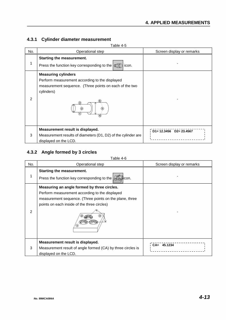
2
Measuring cylinders Perform measurement according to the displayed measurement sequence. (Three points on each of the two cylinders)
-
3 Measurement result is displayed. Measurement results of diameters (D1, D2) of the cylinder are displayed on the LCD.
D1= 12.3456 D2= 23.4567
4.3.2 Angle formed by 3 circles
Table 4-6 No. Operational step Screen display or remarks
1 Starting the measurement.
Press the function key corresponding to the icon. -
2
Measuring an angle formed by three circles. Perform measurement according to the displayed measurement sequence. (Three points on the plane, three points on each inside of the three circles)
-
3 Measurement result is displayed. Measurement result of angle formed (CA) by three circles is displayed on the LCD.
CA= 45.1234
No. 99MCA084A 4-13

4.3.3 Circle Formed by Circle Centers
Table 4-7 No. Operational step Screen display or remarks
1 Starting the measurement.
Press the function key corresponding to the icon. -
2 Inputting the number of circles. Input “Number of circles”, the centers of which form a circle.
Remarks Use 3 to 8 circles.
3
Measuring a circle formed by circle centers. Perform measurement according to the displayed measurement sequence. (Three points on the plane, two points on the line, one point on the side face, three points on each inside of the four circles)
Remarks The left figure shows the order of measuring four circle centers. (Three points are measured for one circle.)
4 Measurement result is displayed. Measurement results of positions (X, Y), diameter (D1), and roundness (F3) of the circle are displayed on the LCD.
X = 12.3456 Y = 23.4567D1= 34.5678 F3= 0.003
4.3.4 Slotted Hole Measurement
Table 4-8 No. Operational step Screen display or remarks
1 Starting the measurement.
Press the function key corresponding to the icon. -
2
Measuring a slotted hole. Perform measurement according to the displayed measurement sequence. (Three points on the plane, two points on the line, one point on the side face, five points on the inside of a slotted hole)
Remarks
3 Measurement result is displayed. Measurement result of positions (X, Y), lengths (L1, L2), and angle (CX) of the slotted hole are displayed on the LCD.
X = 12.3456 Y =23.4567L1= 34.5678 L2=56.7890CX=45.1234
No. 99MCA084A 4-14

4. APPLIED MEASUREMENTS
4.3.5 Rectangular Hole Measurement
Table 4-9 No. Operational step Screen display or remarks
1 Starting the measurement.
Press the function key corresponding to the icon. -
2
Measuring a rectangular hole. Perform measurement according to the displayed measurement sequence. (Three points on the plane, two points on the line, one point on the side face, five points on the inside of a rectangular hole)
Remarks
3 Measurement result is displayed. Measurement results of positions (X, Y), lengths (L1, L2), and angle (CX) of the rectangular hole are displayed on the LCD.
X = 12.3456 Y =23.4567L1= 34.5678 L2=56.7890CX=45.1234
4.3.6 Groove Width Measurement
Table 4-10 No. Operational step Screen display or remarks
1 Starting the measurement.
Press the function key corresponding to the icon. -
2
Measuring a groove width. Perform measurement according to the displayed measurement sequence. (Three points on the plane, two points on the line, three points on the side face)
-
3 Measurement result is displayed. Measurement result of groove width (LC) is displayed on the LCD.
LC = 12.3456
No. 99MCA084A 4-15

4.3.7 V-groove Measurement
Table 4-11 No. Operational step Screen display or remarks
1 Starting the measurement.
Press the function key corresponding to the icon. -
2
Measuring V-groove lengths. Perform measurement according to the displayed measurement sequence. (Three points on the plane, two points on each of the three lines)
Remarks
3 Measurement result is displayed. Measurement results of V-groove lengths (LC, L1, L2) are displayed on the LCD.
LC = 12.3456 L1= 23.4567L2= 34.5678
4.3.8 Section Circle Measurement (Cone)
Table 4-12 No. Operational step Screen display or remarks
1 Starting the measurement.
Press the function key corresponding to the icon. -
2 Inputting a depth. Input a value of "Depth from top surface".
-
3
Measuring a section circle of a cone. Perform measurement according to the displayed measurement sequence. (Three points on the plane, two points on the line, one point on the side face, six points on the inside of a cone)
-
4 Measurement result is displayed. Measurement results of positions (X, Y) and diameter (D1) of the cone are displayed on the LCD.
X = 12.3456 Y = 23.4567D1= 34.5678
No. 99MCA084A 4-16

4. APPLIED MEASUREMENTS
4.3.9 Sphere Diameter Measurement
Table 4-13 No. Operational step Screen display or remarks
1 Starting the measurement.
Press the function key corresponding to the icon. -
2
Measuring a sphere diameter. Perform measurement according to the displayed measurement sequence. (Four points on the sphere)
-
3 Measurement result is displayed. Measurement result of sphere diameter (D1) is displayed on the LCD.
D1= 34.5678
4.3.10 Cone Angle Measurement
Table 4-14 No. Operational step Screen display or remarks
1 Starting the measurement.
Press the function key corresponding to the icon. -
2
Measuring the vertex angle of a cone. Perform measurement according to the displayed measurement sequence. (Three points on each of the two circles)
-
3 Measurement result is displayed. Measurement result of cone vertex angle (T) is displayed on the LCD.
T = 45.1234
No. 99MCA084A 4-17
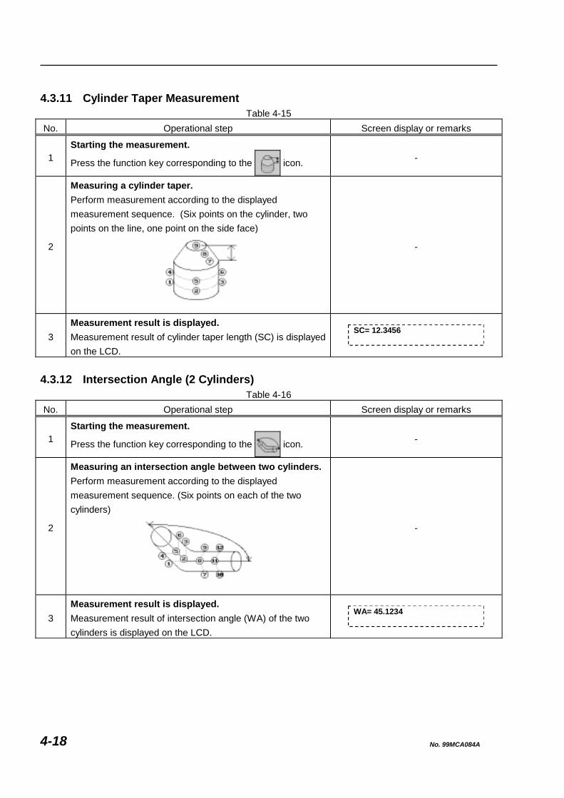
4.3.11 Cylinder Taper Measurement
Table 4-15 No. Operational step Screen display or remarks
1 Starting the measurement.
Press the function key corresponding to the icon. -
2
Measuring a cylinder taper. Perform measurement according to the displayed measurement sequence. (Six points on the cylinder, two points on the line, one point on the side face)
-
3 Measurement result is displayed. Measurement result of cylinder taper length (SC) is displayed on the LCD.
SC= 12.3456
4.3.12 Intersection Angle (2 Cylinders)
Table 4-16 No. Operational step Screen display or remarks
1 Starting the measurement.
Press the function key corresponding to the icon. -
2
Measuring an intersection angle between two cylinders. Perform measurement according to the displayed measurement sequence. (Six points on each of the two cylinders)
-
3 Measurement result is displayed. Measurement result of intersection angle (WA) of the two cylinders is displayed on the LCD.
WA= 45.1234
No. 99MCA084A 4-18

4. APPLIED MEASUREMENTS
4.3.13 Side Length Measurement
Table 4-17 No. Operational step Screen display or remarks
1 Starting the measurement.
Press the function key corresponding to the icon. -
2
Measuring side lengths. Perform measurement according to the displayed measurement sequence. (Three points on the plane, two points on each of the three lines)
Remarks
3 Measurement result is displayed. Measurement results of side lengths (LC, L1, L2) are displayed on the LCD.
LC= 12.3456 L1= 23.4567L2= 34.5678
4.3.14 Corner Circle Measurement
Table 4-18 No. Operational step Screen display or remarks
1 Starting the measurement.
Press the function key corresponding to the icon. -
2
Measuring the radius of a corner circle. Perform measurement according to the displayed measurement sequence. (Three points on the plane, two points on each of the two lines, one point at the vertex)
-
3 Measurement result is displayed. Measurement result of corner circle radius (R1) is displayed on the LCD.
R1= 12.3456
No. 99MCA084A 4-19

4.4 Obtaining Geometrical Deviations [Objective of lesson]
To obtain geometrical deviations.
[Geometrical deviations to be obtained] 1) Straightness (Menu 4/5) 2) Perpendicularity or squareness of two planes (Menu 5/5) 3) Perpendicularity of a plane and a cylinder (Menu 5/5) 4) Perpendicularity of two cylinders (Menu 5/5) 5) Flatness (Menu 4/5) 6) Parallelism of two planes (Menu 5/5) 7) Parallelism of a plane and a cylinder (Menu 5/5) 8) Parallelism of two cylinders (Menu 5/5) 9) Circularity or roundness (Menu 4/5) 10) Coaxiality (Menu 5/5) 11) Concentricity meas. (2 circles) (Menu 5/5) 12) Runout measurement (Menu 5/5)
[Operational procedure]
1) Calling the “Gage-like measurement menu (4/5), or (5/5)”. 2) The icons for various geometrical deviations are displayed on the LCD.
(See the corresponding paragraphs in this section for the subsequent operational procedures.)
NOTE For obtaining the above geometrical deviations, you need not be conscious of aligning the part coordinate system. Therefore, it is very easy to obtain the above geometrical deviations.
No. 99MCA084A 4-20

4. APPLIED MEASUREMENTS
4.4.1 Obtaining Straightness
Table 4-19 No. Operational step Screen display or remarks
1 Starting the measurement.
Press the function key corresponding to the icon. -
2
Measuring a plane and a line. Perform measurement according to the displayed measurement sequence (three points on the plane and eight points on the line).
1 2
3
4 5 6 7 8 9 1011
-
3 Measurement result is displayed. Measurement result (F1) of the straightness is displayed on the LCD.
F1= 0.003
4.4.2 Obtaining Perpendicularity of Two Planes
Table 4-20 No. Operational step Screen display or remarks
1 Starting the measurement.
Press the function key corresponding to the icon. -
2
Measuring two planes. Perform measurement according to the displayed measurement sequence (three points on each plane).
A
A
12
3
4
5
6
-
3 Measurement result is displayed. Measurement result (VT) of the perpendicularity is displayed on the LCD.
VT= 0.003
No. 99MCA084A 4-21

4.4.3 Obtaining Perpendicularity of Plane and Cylinder
Table 4-21 No. Operational step Screen display or remarks
1 Starting the measurement.
Press the function key corresponding to the icon. -
2
Measuring a plane and a cylinder. Perform measurement according to the displayed measurement sequence (three points on the plane and six points on the cylinder).
A
A
12
345
6
78
9
-
3 Measurement result is displayed. Measurement result (VT) of the perpendicularity is displayed on the LCD.
VT= 0.003
No. 99MCA084A 4-22

4. APPLIED MEASUREMENTS
4.4.4 Obtaining Perpendicularity of Two Cylinders
Table 4-22 No. Operational step Screen display or remarks
1 Starting the measurement.
Press the function key corresponding to the icon. -
2
Measuring two cylinders. Perform measurement according to the displayed measurement sequence (six points on each cylinder).
A
A
12
3
45
6
78 9
10 11 12
-
3 Measurement result is displayed. Measurement result (VT) of the perpendicularity is displayed on the LCD.
VT= 0.003
4.4.5 Obtaining Flatness
Table 4-23 No. Operational step Screen display or remarks
1 Starting the measurement.
Press the function key corresponding to the icon. -
2
Measuring a plane. Perform measurement according to the displayed measurement sequence (nine points on the plane).
12
3
45
6
78
9
-
3 Measurement result is displayed. Measurement result (F2) of the flatness is displayed on the LCD.
F2= 0.003
No. 99MCA084A 4-23

4.4.6 Obtaining Parallelism of Two Planes
Table 4-24 No. Operational step Screen display or remarks
1 Starting the measurement.
Press the function key corresponding to the icon. -
2
Measuring two planes. Perform measurement according to the displayed measurement sequence (three points on each plane).
A
A
1
2
3
45 6
-
3 Measurement result is displayed. Measurement result (PA) of the parallelism is displayed on the LCD.
PA= 0.003
4.4.7 Obtaining Parallelism of Plane and Cylinder
Table 4-25 No. Operational step Screen display or remarks
1 Starting the measurement.
Press the function key corresponding to the icon. -
2
Measuring a plane and a cylinder. Perform measurement according to the displayed measurement sequence (three points on the plane and six points on the cylinder).
A
A
1 2
3
45
6
78
9
-
3 Measurement result is displayed. Measurement result (PA) of the parallelism is displayed on the LCD.
PA= 0.003
No. 99MCA084A 4-24
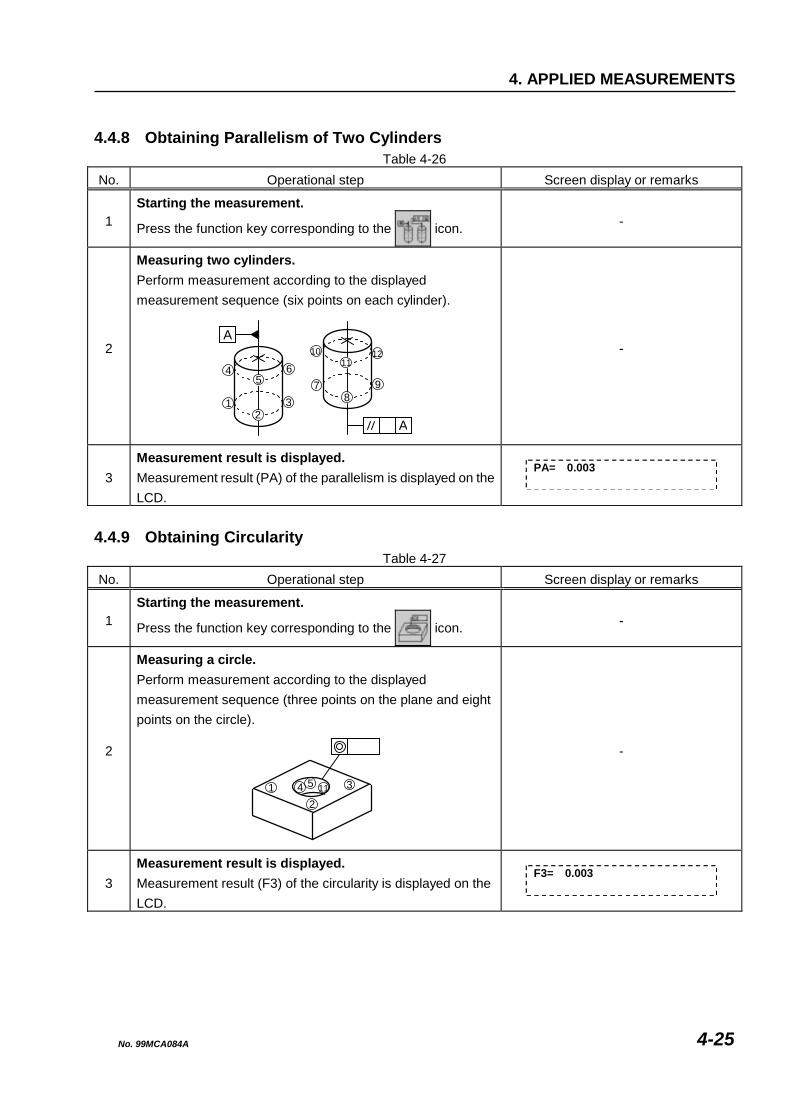
4. APPLIED MEASUREMENTS
4.4.8 Obtaining Parallelism of Two Cylinders
Table 4-26 No. Operational step Screen display or remarks
1 Starting the measurement.
Press the function key corresponding to the icon. -
2
Measuring two cylinders. Perform measurement according to the displayed measurement sequence (six points on each cylinder).
A
12
3
45
6
A
78
9
1011
12
-
3 Measurement result is displayed. Measurement result (PA) of the parallelism is displayed on the LCD.
PA= 0.003
4.4.9 Obtaining Circularity
Table 4-27 No. Operational step Screen display or remarks
1 Starting the measurement.
Press the function key corresponding to the icon. -
2
Measuring a circle. Perform measurement according to the displayed measurement sequence (three points on the plane and eight points on the circle).
12
34 5 11
-
3 Measurement result is displayed. Measurement result (F3) of the circularity is displayed on the LCD.
F3= 0.003
No. 99MCA084A 4-25

4.4.10 Obtaining Coaxiality
Table 4-28 No. Operational step Screen display or remarks
1 Starting the measurement.
Press the function key corresponding to the icon. -
2
Measuring two cylinders. Perform measurement according to the displayed measurement sequence (six points on each cylinder).
A A1
3
4
6
7
8
9
10
11
12
52
-
3 Measurement result is displayed. Measurement result (NN) of the coaxiality is displayed on the LCD.
NN= 0.003
No. 99MCA084A 4-26
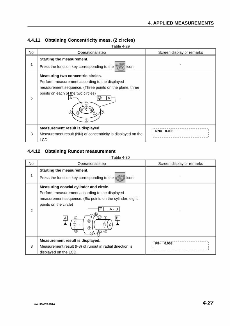
4. APPLIED MEASUREMENTS
4.4.11 Obtaining Concentricity meas. (2 circles)
Table 4-29 No. Operational step Screen display or remarks
1 Starting the measurement.
Press the function key corresponding to the icon. -
2
Measuring two concentric circles. Perform measurement according to the displayed measurement sequence. (Three points on the plane, three points on each of the two circles)
A
7
8
9 13
54 6
2
A
-
3 Measurement result is displayed. Measurement result (NN) of concentricity is displayed on the LCD.
NN= 0.003
4.4.12 Obtaining Runout measurement
Table 4-30 No. Operational step Screen display or remarks
1 Starting the measurement.
Press the function key corresponding to the icon. -
2
Measuring coaxial cylinder and circle. Perform measurement according to the displayed measurement sequence. (Six points on the cylinder, eight points on the circle)
11
A
A - B
1
3
4
6
82
7
9
B
1012
1314
5
-
3 Measurement result is displayed. Measurement result (F8) of runout in radial direction is displayed on the LCD.
F8= 0.003
No. 99MCA084A 4-27

No. 99MCA084A 4-28
MEMO

[MEMO]

Mitutoyo Corporation 20-1, Sakado 1-chome, Takatsu-ku, Kawasaki, Kanagawa 213-0012, Japan Cable: MITUTOYO Kawasaki Phone: (044)813-8230 Fax: (044)813-8231


![No. 99MCA083A1 SERIES No. 198 QM-Data · QM-Data QM-Data 300 3D Data Processing Unit User’s Manual [Software Guide (2)] ... the power is switched off and can be reused when the](https://img.dokumen.tips/doc/110x75/5ece89537b99996cd04cce38/no-99mca083a1-series-no-198-qm-data-qm-data-qm-data-300-3d-data-processing-unit.jpg)