Embed Size (px)
Citation preview

" .No. 1.33.79"4 Automated Mechanical Transmission
Test Summary and Component Analysis
Contract Number DAAE07-86-C-R028
April 1988
R. C. HolmesEaton CorporationCorporate Research & DevelopmentDetroit Center26201 Northwestern HighwayP. 0. Box 766SoEthfield, M_ 48037
By Eaton Technical Report No. 88018
Approved for Public Release19Distribution UnlimitedC
U.S. ARMY TANK-AUTOMOTIVE COMMANDRESEARCH, DEVELOPMENT & ENGINEERING CENTER
WSorchiga 48397M50008
Wapproed, foMPbic elase ,-9-(>..' -

13379
Automated Mechanical TransmissionTest Summary and Component Analysis
Contract Number DAAE07-86-C-R028
April 1988
R. C. HolmesEaton CorporationCorporate Research & DevelopmentDetroit Center26201 Northwestern HighwayP. 0. Box 766Southfield, MI 48037Eaton Technical Report No. 88018
Approved for Public Release:Distribution Unlimited
Unclassified
SECURITY CLASS;FtICAON OF rHIS PAGE
REPORT DOCUMENTATION PAGE
la. REPORT SECURITY CLASSIFICATION lb. RESTRICTIVE MARKINGS
Unclassified
2a. SECURITY CLASSIFICATION AUTHORITY 3 DISTRIBUTION /AVAILABILITY OF REPORT
Approved for Public Release:2b. DECLASSIFICATION IDOWNGRADING SCHEDULE Distribution Unlimited
4. PERFORMING ORGANIZATION REPORT NUMBER(S) S. MONITORING ORGANIZATION REPORT NUMBER(S)
CoRD-DC Technical Report #88018 13379
6a. NAME OF PERFORMING ORGANIZATION 6b. OFFICE SYMBOL 7a. NAME OF MONITORING ORGANIZATIONEaton Corporation IaplabeCorporate Research & (if applicable) U.S. Army Tank-Automotive Command
Development-Detroit Center I
6C. ADDRESS (City, State, and ZIP Code) 7b. ADDRESS (City, State, and ZIP Code)26201 Northwestern HighwaySouthfield, Michigan 48037 Warren, Michigan 48090
Ba. NAME OF FUNDING/SPONSORING 8b. OFFICE SYMBOL 9. PROCUREMENT INSTRUMENT IDENTIFICATION NUMBERORGANIZATION (If applicable) DAAE07-86-C-RO28
8C. ADDRESS (City, State, and ZIP Code) 10. SOURCE OF FUNDING NUMBERS
PROGRAM PROJECT TASK WORK UNITELEMENT NO. NO. NO. ACCESSION NO.
11. TITLE (Include Security Classification)
Automated Mechanical Transmission Test Summary and Component Analysis (u)
12. PERSONAL AUTHOR(S)Holmes, Russell C.
13a. TYPE OF REPORT 13b. TIME COVERED 14. DATE OF REPORT (Year, Month, Day) 15. PAGE COUNTFinal FROM 86 Feb To 8 7 Nov 88 April 113
16. SUPPLEMENTARY NOTATION
17 COSATI CODES 18. SUBJECT TERMS (Continue on reverse if qssalv anf identify by block pumber)
FIELD GROUP SUB-GROUP M939 Truck, Technical Feasiblily Test AutomaticTransmission, Automated Mechanical Transmission,
Electronic Transmission Controls
19. ABSTRACT (Continue on reverse if necessary and identify by block number)
Eaton Corporation has contracted with the United States Army to design, develop and
deliver a prototype automated mechanical transmission system for the M939-series 5-ton
truck to demonstrate technical feasibility. The system design used the Eaton TSO-11616
transmission in combination with the Cummins NHC-250 engine and Spicer AS1402SD heavy-
duty clutch.
Test plans were conducted at Eaton and Aberdeen Proving Grounds to evaluate both
performance and durability. This report covers the test results, teardown inspectionand transmission rebuild for the Modern Technology demonstration truck.
20. DISTRIBUTION/AVAILABILITY OF ABSTRACT 21. ABSTRACT SECURITY CLASSIFICATION
EJUNCLASSIFIED/UNLIMITEO 0 SAME AS RPT. 0 DTIC USERS Unclassified22a. NAME OF RESPONSIBLE INDIVIDUAL 22b. TELEPHONE (Include Area Code) 22c. OFFICE SYMBOL
Mark Mushenski 313-574-8532 AMSTA-RGT
DD FORM 1473, 84 MAR 83 APR edition may be used until exhausted. SECURITY CLASSIFICATION OF THIS PAGE
All other editions are obsolete. Unclassified
/1

SECURITY CLASSIFICATION OF THIS PAGE
SECURITY CLASSIFICATION OF THIS PAGE2

ACKNOWLEDGEMENTS
Major contributions to this report were made by William Pankratz, Senior Product Engineer,Eaton Corporate Research and Development, Donald Speranza, Manager ElectronicsTechnology, Eaton Drivetrain Systems Division and Timothy Morscheck, Manager MilitaryPrograms, Eaton Transmission Division.
3

4

SUMMARY
Automated mechanical transmissions have been developed by adding electronic controls,actuators and sensors to manual operated master clutch and multispeed transmissionassemblies to achieve fully automatic operation.
An automated mechanical transmission with an integral transfer case was designed,developed and delivered to the U. S. Army Tank-Automotive Command (TACOM) in anM939- series 5-Ton Tactical Truck. This system was subjected to a Technical FeasibilityTest at Aberdeen Proving Grounds, which included a 10,000-mile endurance test over theMunson, Perryman and Churchville test courses.
The transmission system successfully passed the test plan, which would indicate that theperformance and reliability of the M939-series 5-ton performance would not be jeopardizedby this alternative automatic transmission concept.
This report specifically addresses the teardown inspection upon completion of the AberdeenTechnical Feasibility Test and the rebuild of the transmission system for the "ModernTechnology Demonstration" 5-ton truck being assembled for the TACOM by General Motors- Military Vehicles Operation.
5

6

TABLE OF CONTENTS
Section Page
1.0. INTRO DUCTIO N ................................................... 17
2.0. STATEMENT OF OBJECTIVES ........................................ 17
3.0. C O NC LUSIO NS .................................................... 18
4 .0. D ISC USSIO N ...................................................... 19
4.1. Description of Transmission System ....... ......................... 19
4.2. Prediction of Performance ..... .................................. 23
4.3. Specification Sheets . ............................................ 31
4.4. Test Plan at Eaton P.G. ........................................... 32
4.4.1. Description of Tests ............................................... 324.4.2. Summary of Test Data - Before and After APG ........................ 34
4.5. Aberdeen Proving Ground Test .. .................................. 35
4.5.1. Description of Test Plan ............................................ 35
4.5.2. Sum m ary of Results ............................................... 35
4.5.3. Problem Description/Solution ........................................ 37
4.6. Disassembly and Inspection .......... ............................ 37
4.6.1. Master Clutch Description .......................................... 37
4.6.2. M aster C lutch .................................................... 40
4.6.3. Transmission Mechanical Description ................................. 49
4.6.4. Park Brake Description ............................................. 85
4.6.5. Park Brake Inspection .............................................. 85
4.6.6. Main Box Air Shifter Description ..................................... 99
4.6.7. Main Box Air Shifter Inspection ...................................... 99
4.6.8. Auxiliary Box Air Shifter Description .................................. 99
4.6.9. Auxiliary Box Air Shifter Inspection ................................... 99
4.6.10. Input Brake Description ............................................. 102
4.6.11. Input Brake Inspection ............................................. 102
4.7. Rebuild for Modern Technology Demonstration Truck .................... 102
4.7.1. M echanical System ................................................ 102
4.7.2. Im proved Acceleration Tim es ....................................... 104
4.7.3. Electronic Control System .......................................... 104
SELECTED BIBLIOGRAPHY .................................................... 113
7

8

TABLE OF CONTENTS (Continued)
Page
APPENDIX A - Product Literature & Operation of the Eaton Fuller"CEEMATý" Transmission ....................................... A-1
APPENDIX B - Eaton Proving Ground Test Plan and Data Sheets ................... B-1APPENDIX C - Processing Analysis of Countershaft Gear PN 56453 ................. C-1APPENDIX D - Drop Box Gears - Surface Residual Stress ......................... D-1APPENDIX E - Drop Box Gears - Residual Stress ................................ E-1APPENDIX F - Inspection Report on AUSCO's Brake ............................. F-1APPENDIX G - Operating Instructions for the TSO-1 1616 Automated Mechanical
Transmission with Integral Transfer Case .......................... G-1
DISTRIBUTION LIST .......................................................... Dist-1
9

10

LIST OF ILLUSTRATIONS
Figure Title Page
4-1. System Block Diagram ................................................................. 22
4-2. Cummins NHC - 250 Engine Performance ......................................... 24
4-3. Highway Performance ................................................................... 26
4-4. Performance at 50,000 lbs .............................................................. 27
4-5. Performance at 35,000 lbs .............................................................. 28
4-6. Gradeability vs. MPH ................................................................... 29
4-7. Spicer Clutch Assembly ................................................................. 41,
4-8. Clutch Plate Wear Profile (Partial Trace) ............................................. 47
4-9. Front Friction Disc ................................................................... 51
4-10. Interm ediate Plate ......................................................................... 53
4-11. Rear Friction Disc ........................................................................ 55
4-12. Transmission Main and Auxiliary Section ............................................ 57
4-13. Transmission and Integral Drop Box ................................................... 59
4-14. Exterior View of Transmission ........................................................... 61
4-15. Front Mainshaft Gears .................................................................... 73
4-16. Auxiliary Mainshaft Gears .............................................................. 75
4-17. Countershaft Gears ..................................................................... 77
4-18. Drop Box G ears ........................................................................... 79
4-19. Dog C lutches ............................................................................. 83
4-20. Front Wheel Drive Fork ................................................................ 87
4-21. 3-4 Fork .................................................................................. 89
4-22. 1-2 Fork .................................................................................. 91
4-23. Low Fork .................................................................................. 93
4-24. Intermediate-Overdrive Fork ........................................................... 95
4-25. D irect Fork ................................................................................. 97
11

12

LIST OF ILLUSTRATIONS (Continued)
Figure Title Page
4-26. Main Box Air Shifter Assembly ...................................... 100
4-27. Main Box Air Shifter Fork Arrangement ............................... 101
4-28. External Input Brake Assembly ...................................... 103
4-29. Locking Spline .................................................... 105
4-30. Air Exhaust Manifold ............................................... 107
13

14
LIST OF TABLES
Figure Title Page
4-1. Transm ission Ratios ................................................ 21
4-2. Transmission Specifications .......................................... 33
4-3. Conditions of Load ................................................. 36
4-4. Endurance Test Cycle .............................................. 38
4-5. Technical Feasibility Test/Aberdeen Proving GroundsCategorization of Problems and Failure ................................ 39
4-6. Master Clutch W ear ................................................ 45
4-7. Fork W ear ........................................................ 86
4-8. Acceleration Data ................................................. 108
15

16

1.0. INTRODUCTION
This final technical report, prepared by the Corporate Research & Development-DetroitCenter of Eaton Corporation for the U. S. Army Tank-Automotive Command (TACOM)under Contract DAAE07-86-C-R028, describes the teardown inspection and analysis of theTSO-1 1616 automated mechanical transmission with integral transfer case upon completionof a successful Technical Feasibility Test performed at the U. S. Army Aberdeen ProvingGround, Aberdeen, Maryland. In addition, a summary of the Eaton-performed test plan, aswell as the Aberdeen Proving Ground test plan, is included. The TSO-1 1616 automatedmechanical transmission was rebuilt with significant improvements for the TACOM'S ModernTechnology Demonstrator 5-ton truck. The changes in construction and performance arealso described.
Eaton Corporation is a major worldwide supplier of heavy-duty, constant-mesh, manuallyoperated truck transmissions. Eaton Corporate Research & Development-Detroit Center hasbeen applying electronics to transmission controls since the early 1970's. In themid-1970's, automation of mechanical transmissions and clutches was demonstrated, anda significant program to apply transmission automation techniques to commercialtransmissions was initiated in 1980.
Along with the dry clutch approach, Eaton also pursued the more traditional route anddeveloped an automated mechanical transmission that utilizes a torque converter.Information on this unit is found in Appendix A.
The remainder of this report will concern itself with the dry clutch transmission.
This technology was demonstrated to TACOM personnel and, consequently, the followingseries of contracts were issued to Eaton Corporation for evaluation, design, development,test, field service and teardown analysis and rebuild of a transmission system.
* DAAE07 - 81-C-4054, Evaluation Study and Preliminary Test* DAAE07 - 82-C-4121, Design and Development0 DAAE07 - 85-R-R194, Field Service Support9 DAAE07 - 86-C-R028, Teardown Analysis and Rebuild
As a result of the U. S. Army initiative, a 16-speed automated mechanical transmissionusing a standard Spicer AS1402SD clutch along with an integral transfer case wasdesigned, developed and tested. The performance requirements of the standard M939-series 5-ton tactical truck were used as the performance and durability specification.
Test plans at Eaton Proving Grounds and Aberdeen Proving Grounds have shown that theM939 performance specifications can be achieved without sacrifice or limitations inoperation. Both at the system level and the component level there are no capability ordurability limitations demonstrated that should preclude the pursuit of this alternativeautomatic transmission technology for U. S. Army tactical trucks.
2.0. STATEMENT OF OBJECTIVES
The primary goal was to evaluate Eaton Corporation's Automated Mechanical Transmissiontechnology in a U. S. Army M939-series 5-ton tactical truck. A 16-speed automatictransmission was designed, developed, tested, inspected and rebuilt for this purpose.
17
3.0. CONCLUSIONS
3.1. Teardown Inspection
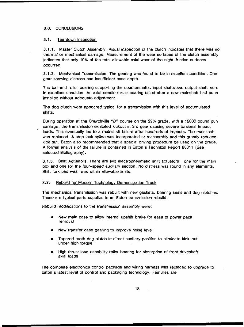
3.1.1. Master Clutch Assembly. Visual inspection of the clutch indicates that there was nothermal or mechanical damage. Measurement of the wear surfaces of the clutch assemblyindicates that only 10% of the total allowable axial wear of the eight-friction surfacesoccurred.
3.1.2. Mechanical Transmission. The gearing was found to be in excellent condition. Onegear showing distress had insufficient case depth.
The ball and roller bearing supporting the countershafts, input shafts and output shaft wereIn excellent condition. An axial needle thrust bearing failed after a new mainshaft had beeninstalled without adequate adjustment.
The dog clutch wear appeared typical for a transmission with this level of accumulatedshifts.
During operation at the Churchville "B" course on the 29% grade, with a 15000 pound guncarriage, the transmission exhibited kickout in 3rd gear causing severe torsional impactloads. This eventually led to a mainshaft failure after hundreds of impacts. The mainshaftwas replaced. A step lock spline was incorporated at reassembly and this greatly reducedkick out. Eaton also recommended that a special driving procedure be used on the grade.A formal analysis of the failure is contained in Eaton's Technical Report 86011 (Seeselected Bibliography).
3.1.3. Shift Actuators. There are two electropneumatic shift actuators: one for the main
box and one for the four-speed auxiliary section. No distress was found in any elements.Shift fork pad wear was within allowable limits.
3.2. Rebuild for Modern Technology Demonstration Truck
The mechanical transmission was rebuilt with new gaskets, bearing seals and dog clutches.These are typical parts supplied in an Eaton transmission rebuild.
Rebuild modifications to the transmission assembly were:
"* New main case to allow internal upshift brake for ease of power packremoval
"• New transfer case gearing to improve noise level
"* Tapered tooth dog clutch in direct auxiliary position to eliminate kick-outunder high torque
" High thrust load capability roller bearing for absorption of front driveshaftaxial loads
The complete electronics control package and wiring harness was replaced to upgrade toEaton's latest level of control and packaging technology. Features are
18
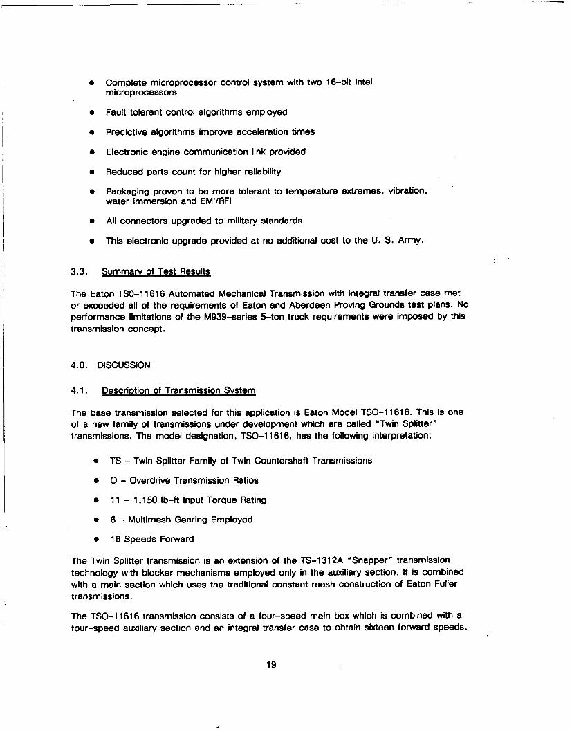
* Complete microprocessor control system with two 16-bit Intel
microprocessors
e Fault tolerant control algorithms employed
e Predictive algorithms improve acceleration times
e Electronic engine communication link provided
9 Reduced parts count for higher reliability
e Packaging proven to be more tolerant to temperature extremes, vibration,water immersion and EMI/RFI
e All connectors upgraded to military standards
e This electronic upgrade provided at no additional cost to the U. S. Army.
3.3. Summary of Test Results
The Eaton TSO-1 1616 Automated Mechanical Transmission with integral transfer case metor exceeded all of the requirements of Eaton and Aberdeen Proving Grounds test plans. Noperformance limitations of the M939-series 5-ton truck requirements were imposed by thistransmission concept.
4.0. DISCUSSION
4.1. Description of Transmission System
The base transmission selected for this application is Eaton Model TSO-1 1616. This is oneof a new family of transmissions under development which are called "Twin Splitter"transmissions. The model designation, TSO-1 1616, has the following interpretation:
* TS - Twin Splitter Family of Twin Countershaft Transmissions
* 0 - Overdrive Transmission Ratios
* 11 - 1,150 lb-ft Input Torque Rating
* 6 - Multimesh Gearing Employed
* 16 Speeds Forward
The Twin Splitter transmission is an extension of the TS-1312A "Snapper" transmissiontechnology with blocker mechanisms employed only in the auxiliary section. It is combinedwith a main section which uses the traditional constant mesh construction of Eaton Fullertransmissions.
The TSO-1 1616 transmission consists of a four-speed main box which is combined with afour-speed auxiliary section and an integral transfer case to obtain sixteen forward speeds.
19
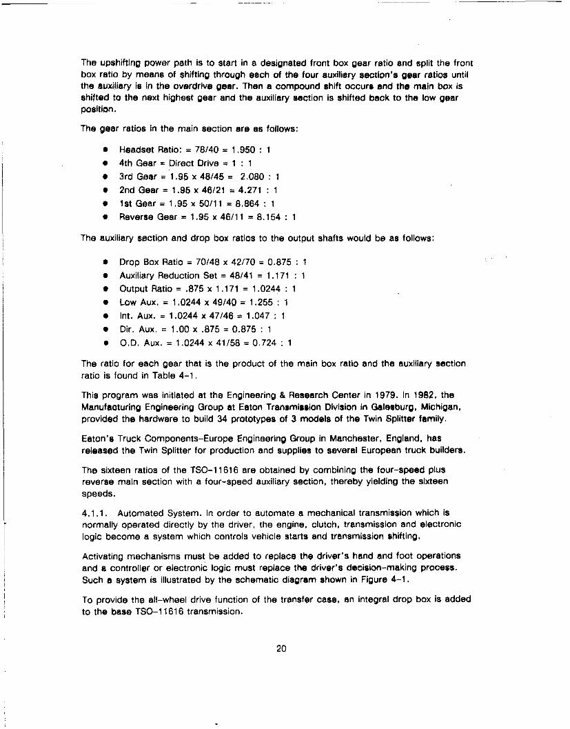
The upshifting power path is to start in a designated front box gear ratio and split the frontbox ratio by means of shifting through each of the four auxiliary section's gear ratios untilthe auxiliary is in the overdrive gear. Then a compound shift occurs and the main box isshifted to the next highest gear and the auxiliary section is shifted back to the low gearposition,
The gear ratios in the main section are as follows:
* Headset Ratio: = 78/40 = 1.950 : 1
* 4th Gear = Direct Drive = 1 : 1* 3rd Gear = 1.95 x 48/45= 2.080 :1* 2nd Gear = 1.95 x 46/21 = 4.271 : 10 1st Gear = 1.95 x 50/11 = 8.864 : 1* Reverse Gear = 1.95 x 46/11 = 8.154 : 1
The auxiliary section and drop box ratios to the output shafts would be as follows:
* Drop Box Ratio = 70/48 x 42/70 = 0.875 : 1* Auxiliary Reduction Set = 48/41 = 1.171 : 1
0 Output Ratio = .875 x 1.171 = 1.0244 : 1
* Low Aux. 1.0244 x 49/40 = 1.255 :1
* Int. Aux. = 1.0244 x 47/46 = 1.047 : 1* Dir. Aux. = 1.00 x .875 = 0.875 : 1
* O.D. Aux. = 1.0244 x 41/58 = 0.724 : 1
The ratio for each gear that is the product of the main box ratio and the auxiliary sectionratio is found in Table 4-1.
This program was initiated at the Engineering & Research Center in 1979. In 1982, theManufacturing Engineering Group at Eaton Transmission Division in Galesburg, Michigan,provided the hardware to build 34 prototypes of 3 models of the Twin Splitter family.
Eaton's Truck Components-Europe Engineering Group in Manchester, England, hasreleased the Twin Splitter for production and supplies to several European truck builders.
The sixteen ratios of the TSO-1 1616 are obtained by combining the four-speed plusreverse main section with a four-speed auxiliary section, thereby yielding the sixteenspeeds.
4.1.1. Automated System. In order to automate a mechanical transmission which isnormally operated directly by the driver, the engine, clutch, transmission and electroniclogic become a system which controls vehicle starts and transmission shifting.
Activating mechanisms must be added to replace the driver's hand and foot operationsand a controller or electronic logic must replace the driver's decision-making process.Such a system is illustrated by the schematic diagram shown in Figure 4-1.
To provide the all-wheel drive function of the transfer case, an integral drop box is added
to the base TSO-1 1616 transmission.
20

Table 4-1. Transmission Ratios
Gear Ratio %Step
Rev Low 8.154 x 1.255= 10.23
Rev Dir 8.154 x .875 = 7.13
1 - 1st Low 8.86 x 1.255 = 11.1219.9%
2 - 1st Int 8.86 x 1.047 = 9.2819.6%
3 - 1st Dir 8.864 x .875 = 7.7620.8%
4 - 1st O.D. 8.864 x .724 = 6.4219.7%
5 - 2nd Low 4.271 x 1.255 = 5.3619.9%
6 - 2nd Int 4.271 x 1.047 = 4.4719.6%
7 - 2nd Dir 4.271 x .875 = 3.7420.8%
8 - 2nd O.D. 4.271 x .724 = 3.0918.5%
9 - 3rd Low 2.08 x 1.255= 2.6119.9%
10 - 3rd Int 2.08 x 1.047= 2.1819.6%
11 - 3rd Dir 2.08 x .875 = 1.8220.8%
12 - 3rd O.D. 2.08 x .724 = 1.5120.0%
13 - 4th Low 1 x 1.255 = 1.2619.9%
14 - 4th Int 1 x 1.047 = 1.0519.6%
15 - 4th Dir 1 x .875 = .87520.8%
16 - 4th O.D. 1 x .724 = .724
Overall Reduction Ratio = 11.12/.724 = 15.36
21

SE
5us SM
CL
x
0 40
0 (0
.Figure 4-1 System Block Diagram
22
z• 6
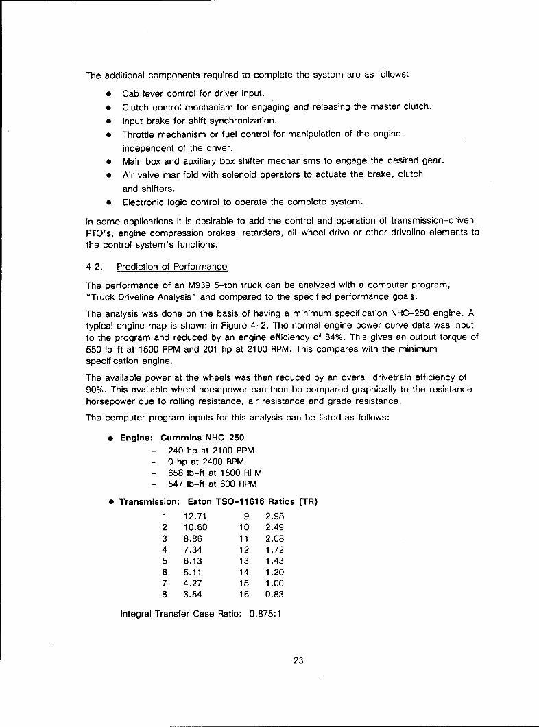
The additional components required to complete the system are as follows:
* Cab lever control for driver input.
* Clutch control mechanism for engaging and releasing the master clutch.
* Input brake for shift synchronization.
* Throttle mechanism or fuel control for manipulation of the engine,
independent of the driver.
* Main box and auxiliary box shifter mechanisms to engage the desired gear.
* Air valve manifold with solenoid operators to actuate the brake, clutch
and shifters.
• Electronic logic control to operate the complete system.
In some applications it is desirable to add the control and operation of transmission-drivenPTO's, engine compression brakes, retarders, all-wheel drive or other driveline elements to
the control system's functions.
4.2. Prediction of Performance
The performance of an M939 5-ton truck can be analyzed with a computer program,"Truck Driveline Analysis" and compared to the specified performance goals.
The analysis was done on the basis of having a minimum specification NHC-250 engine. A
typical engine map is shown in Figure 4-2. The normal engine power curve data was input
to the program and reduced by an engine efficiency of 84%. This gives an output torque of550 lb-ft at 1500 RPM and 201 hp at 2100 RPM. This compares with the minimumspecification engine.
The available power at the wheels was then reduced by an overall drivetrain efficiency of
90%. This available wheel horsepower can then be compared graphically to the resistancehorsepower due to rolling resistance, air resistance and grade resistance.
The computer program inputs for this analysis can be listed as follows:
"* Engine: Cummins NHC-250- 240 hp at 2100 RPM- 0 hp at 2400 RPM- 658 lb-ft at 1500 RPM- 547 lb-ft at 600 RPM
"* Transmission: Eaton TSO-11616 Ratios (TR)
1 12.71 9 2.982 10.60 10 2.493 8.86 11 2.084 7.34 12 1.725 6.13 13 1.436 5.11 14 1.207 4.27 15 1.008 3.54 16 0.83
Integral Transfer Case Ratio: 0.875:1
23

------ I-.- 4-
---- *-- -- - -- -
-.-- *~~~~1LL)
-~d. indT.¾ -.ý - ~i
-' _ +__ 14 +-+H
77- -4 4 -4 44+~- ---- -
OS H . I I~Jt~T' ~ic ! IS-I
I-I--------- J
TZIK ' <12 1 m __; I-- -i -IJ FT --..------- I
-~ t-
!4 ýC I_____4_ (L4-81) 3fD tl 4J-
Figure~ ~ ~ ~ ~~tt 4- umnsNG2 niePefrac62

"* Axle Ratio:- 6.433:1 (AR)
"* Efficiencies:- Engine - 84% (ENEFF)- Drivetrain - 90% (DREFF)
"* Tires:- 485 rev/mile- Rolling Radius = 20.8 inches (RR)
"* Rolling Resistance:- 26 pound/ton (RES)(good concrete or asphalt)
"* Aerodynamic Resistance; 2- Frontal Area = 72.8 ft. (FA)- Drag Coefficient, CD = 0.7
" GVW's:- 35,000 lbs. (cross country)- 50,000 lb. (cross country +
towed load)- 70,000 lbs. (max. highway load)
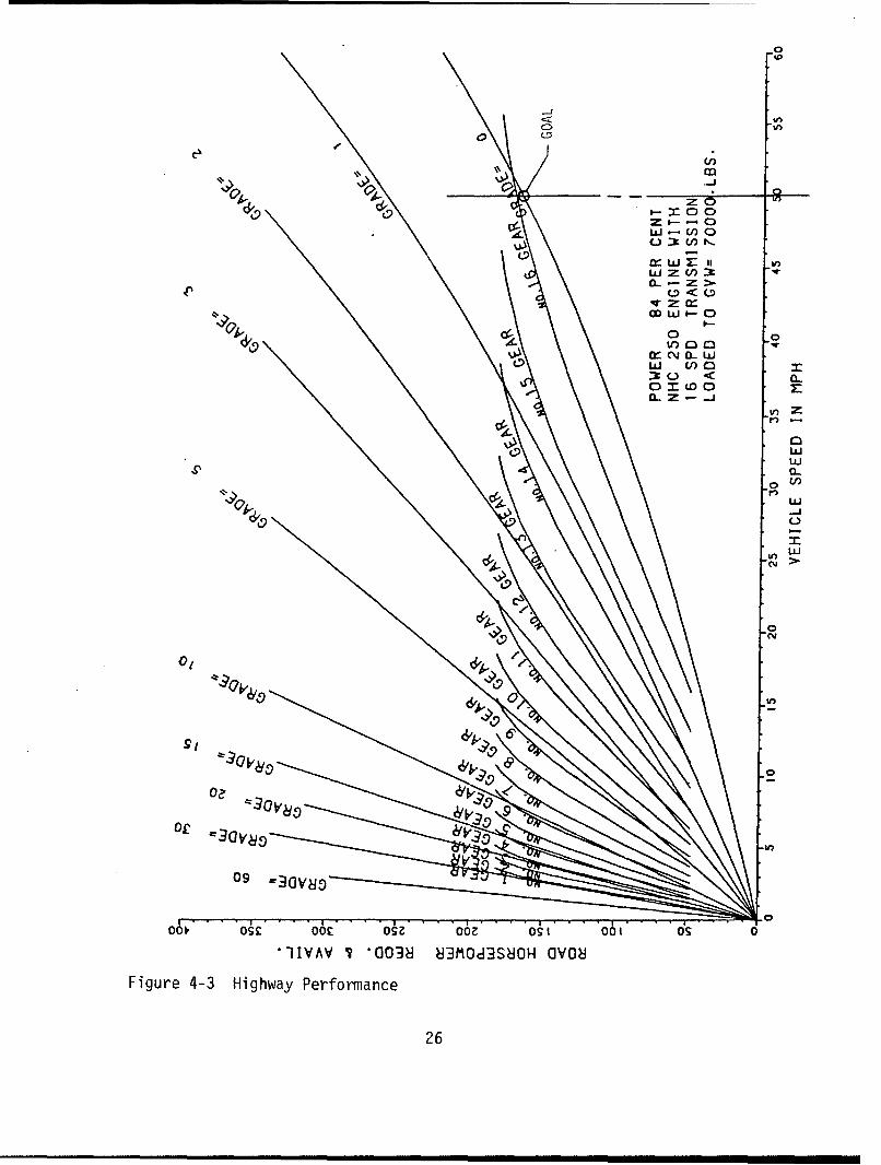
The predicted performance against the performance goals can be summarized by reviewingthe graphical computer output asfollows:
"* Highway Goal: 50 mph on level roadway at 70,000 lb. GCW. Figure 4-3illustrates that the vehicle can reach 52 mph on a level road with theminimum engine specification.
"* Low-Speed Operation: Operate at 2.5 mph with engine at max. torquespeed range. The engine speed with this gearing is 1447 rpm at 2.5 mph.
"* Grade Operation at 50,000 lbs. GVW: Ascend a 2% grade at 30 mph.Figure 4-4 indicates that a speed of 36 mph is achievable in 14th gear ona 2% grade with the minimum specification engine.
"* Grade Operation at 35,000 lbs. GVW: Ascend a 60% grade at a minimumspeed of 2.5 mph. From Figure 4-5 is can be seen that a speed of 3.5mph can be achieved in first gear on a 60% grade with a minimumspecification engine.
To give a better understanding of the gradability potential in the lower gears, anothercomputer calculation is made, and a graph of gradability vs. vehicle speed for the firstseven gears is shown in Figure 4-6.
25
C)00~
-J0.
L) _-ZU) f)
0j U))-a0v z
C 0< 0
CL Z- -J
U)
W
010
6''
0fc
090
1IIVAV 7 a0038 83MO83S8H aV08iFigure 4-3 Highway Performance
26

U;
zo
L9 U-z> S,0 -cEnU0:w 2 1
ci i :ia3c..) 0
UZ
w
LUI
-j I
C-)
o " U, L
090
06f, osk 6r Oz 06, os 001(s
1IIVAV 7 *0O38 ?JJOd3S8OH OVONFigure 4-4 Peformance at 50,000 lbs
27

z6 •0 •IO0
•Z•
•W•O
0
• •
Nm
oo• o• oo• o• ooa o•t oo• o• o• TIVAV • "003• •3MOd3S•OH OVO•
Figure 4-5 Performance at 35,000 Ibs.
28
S' , , , i t I i I I I I I I

V),
GEARS 1 THRU 716 SPEED TRANSMISSION
1 CRADEADILITY PER CENT
NHC 250 ENGINE35,000 LB. GVI4
UJ 2
V)
U-6Lo7
<
VEHCL SEEDiNMP
Figue 46 Grdeailit vs MP
cy29

Gradability can be defined by the following equations for any rpm or vehicle speed.
Gradability = Tan [Arc Sin (ETE/GVW)]
Where:
ETE = Excess Tractive Effort - lbs.GVW = Vehicle Weight - lbs.
ETE = ATE - ZTE
Where:
ATE = Available Tractive EffortATE = Torque x ENEFF x TR x AR x DREFF x 12/RRZTE = Zero Grade Resistance ForcesZTE = GVW/2000 x RES + .0026 x CD x FA x MPH2
This "gradability" term assumes that all the available tractive effort in excess of the rollingresistance and aerodynamic resistance is available for overcoming the grade calculated.
Again, the engine data used is for the minimum specification engine. From zero to 1 mphthe calculation assumes that the clutch will transmit the typical Cummins engine clutchengagement torque of 600 lb-ft at a speed just above idle.
In actual conditions, the torque transmitted during the slipping condition is a function ofhow much throttle depression is made by the driver, the rate of clutch application and thetorque capacity of the clutch.
The electronic control attempts to maintain an engine speed during this slipping mode as afunction of the throttle position.
The farther the throttle pedal is depressed, the higher the engine speed and the resultingengine torque would be during the start.
As can be seen from the analysis, the stated performance goals can be achieved with theTSO-1 1616 gear ratios and a minimum specification engine.
The automated mechanical transmission system described offers benefits over the existingtransmission and two-speed transfer case presently used in M939 5-ton army trucks.
Elimination of the torque converter offers:
* higher efficiency
* significantly less heat rejection, which reduces the engine cooling load,radiator size and plumbing requirements
e improved fuel economy
Elimination of the two-speed transfer case by having sufficient reduction in the transmissionoffers:
"* simpler installation by reducing the number of driveshafts from four to twoand also eliminating the center bearing mounting.
"* better U-joint angles under all conditions of operation.
"* potential of lower original equipment cost for the drivetrain system.
30

The use of an automatic transmission with a high number of ratios and small ratio stepsover the entire speed range offers advantages over gathered ratio steps transmission.
"* The average available horsepower over the entire operating range of thetransmission is higher.
"* Optimization of shift points for operating at lower speeds, especially atpart throttle, for better fuel economy is easily achieved.
"* The frequency of shifting is not of any significance since the driver is notinvolved.
The less complex mechanical construction in the gear boxes simplifies maintenance andreduces rebuilding cost, but the use of a simpler mechanical construction than existingpowershift transmissions increases the level of complexity required in the electroniccontroller. The demand on the electronic controller for causing and sensing thesynchronous engagement of dog clutches will ultimately require the use of a very-fast-processing, 16-bit microprocessor-based controller.
It also should be recognized that using fixed ratio gearing to replace the torque convertercreates a requirement for a large number of shifts between ratios to occur in thelow-speed, off-road environment. The number of shifts required per mile in off-highwayoperation is much higher, but the total number of shifts required over the lifetime of thevehicle is comparable to the requirements for a commercial highway truck.
4.3. Specification Sheets
The application of the Eaton Automated Mechanical Transmission for this contract is tomeet the United States Army requirements for a 5-ton M939-Series truck. The mechanicaltransmission to be adapted shall have rated capacity and gear ratios to meet theperformance goals and eliminate the requirement of additional gear reduction or multiplespeeds in a transfer case.
The specific performance goals can be summarized as follows:
* Fully automatic operation (no clutch pedal).
* Operation without special provisions.
* Operation in the temperature range of +120°F to -25OF without specialequipment.
* Operation with an engine of 210-225 observed hp at 2100 rpm and atorque of 550-650 lb-ft observed.
* Highway Operation - the vehicle at 70,000 pounds GCW shall operate at50 mph on level roadway.
* Low-Speed Operation - the vehicle shall operate at a speed not toexceed 2-1/2 mph with the engine in the maximum torque speed range.
* Grade Operation- At a GCW of 50,000 pounds, the vehicle shall ascend a grade of 2%
at a speed not less than 30 mph.
- At a GVW of 35,000 pounds, the cross-country payload withouttowed load, the vehicle shall ascend a grade of 60% at a minimumspeed of 2.5 mph. The grade surface shall be smooth, dry concrete.
- The vehicle shall demonstrate gradability operations onprepared grades without stalling, overheating or upsetting.
31
The above is a condensation of the M939 performance goals as outlined in Attachment 1 of
the contract DAAE07-82-C-4121. See Table 4-2 for transmission specifications.
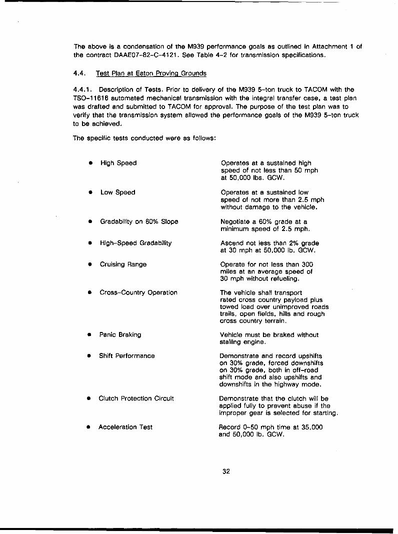
4.4. Test Plan at Eaton Proving Grounds
4.4.1. Description of Tests. Prior to delivery of the M939 5-ton truck to TACOM with theTSO-1 1616 automated mechanical transmission with the integral transfer case, a test planwas drafted and submitted to TACOM for approval. The purpose of the test plan was toverify that the transmission system allowed the performance goals of the M939 5-ton truckto be achieved.
The specific tests conducted were as follows:
"* High Speed Operates at a sustained highspeed of not less than 50 mphat 50,000 lbs. GCW.
"* Low Speed Operates at a sustained lowspeed of not more than 2.5 mphwithout damage to the vehicle.
"* Gradability on 60% Slope Negotiate a 60% grade at aminimum speed of 2.5 mph.
"* High-Speed Gradability Ascend not less than 2% gradeat 30 mph at 50,000 lb. GCW.
"* Cruising Range Operate for not less than 300miles at an average speed of30 mph without refueling.
"• Cross-Country Operation The vehicle shall transportrated cross country payload plustowed load over unimproved roadstrails, open fields, hills and roughcross country terrain.
"• Panic Braking Vehicle must be braked withoutstalling engine.
"* Shift Performance Demonstrate and record upshiftson 30% grade, forced downshiftson 30% grade, both in off-roadshift mode and also upshifts anddownshifts in the highway mode.
"* Clutch Protection Circuit Demonstrate that the clutch will beapplied fully to prevent abuse if theimproper gear is selected for starting.
"* Acceleration Test Record 0-50 mph time at 35,000and 50,000 lb. GCW.
32

Table 4-2. Transmission Specifications
Rating Input TorqueTransmission with T-Case 650 lb-ftTransmission w/o T-Case 1150 lb-ft
Mounting Engine SAE No. 1 or No. 2 clutch housingVehicle 3-bolt vertical mounting pad each side
Controls Type Electronic logic with pneumatic valvesfor complete automation of clutchand transmission
Clutch Type 14 in. diameter, 2-plate, pull-typeLining Ceramic
Gearing Type Constant mesh, spur gearsOverall Ratio 15.34:1 with 16 speeds and 20% stepsTransfer Case Ratio 0.875:1Gear Ratios with T-Case
First 11.12:1Second 9.28:1Third 7.76:1Fourth 6.42:1Fifth 5.36:1Sixth 4.47:1Seventh 3.74:1Eighth 3.09:1Ninth 2.61:1Tenth 2.18:1Eleventh 1.82Twelvth 1.51Thirteenth 1.26:1Fourteenth 1.05:1Fifteenth 0.875:1Sixteenth 0.724:1
Low Reverse 10.23:1High Reverse 7.13:1
Reverse Overall Ratio 14.13:1
Oil System Oil Type SAE 30 Engine OilMIL-L-2104C or MIL-L-46152
Oil Cooler OptionalCapacity with T-Case 20 QuartsCapacity w/o T-Case 15 Quarts
Dimensions Length (w/o Parking Brake) 39.08 inches(with T-Case) Width 26.90 inches
Height 26.12 inchesWeight (dry) 1290 lbs.
Dimensions Length (w/o Parking Brake) 42.20 inches(w/o T-Case) Width 21.10 inches
Height 22.63 inchesWeight (Dry) 956.5 lbs.
33
The above tests were completed during March and April in 1985. After completion of theAberdeen Proving Grounds test plan, the following tests were redone to verify that the initialcapability still existed.
e 60% Gradability Negotiate a 60% grade at a
minimum speed of 2.5 mph.
* Panic Braking Engine not stalled
* Acceleration Test
The description of the test plan and the completed data sheets are contained in AppendixB.
4.4.2. Summary of Test Results.
4.4.2.1. Test A - high speed at 50,000 GCW. The test was repeated twice while doinglaps around the 1.6-mile oval at Eaton's Proving Ground. The oval has a long grade ofapproximately 1% on the west side and a short 7% down grade on the east side. On atypical lap the speed range was from 51.7 to 58.7 mph in the 16th gear. The test goal of50 mph minimum was surpassed.
4.4.2.2. Test B - low speed. The test consisted of driving for 2 miles (48 minutes) at aspeed of 2.5 mph, which is a walking speed. A torque converter type transmission may notget out of slip in this speed range and face a significant heat buildup. Without a torqueconverter, the TSO-1 1616 automated mechanical transmission would actually cool downbecause the power loss was lower than the heat loss dissipation due to convection andradiation. At a 501F ambient, the transmission oil cooled from 125°F to 110°F.
At a 631F ambient, the transmission oil went from 1501F down to 120 0 F.
4.4.2.3. Test C - 60% grade tests. It was successfully demonstrated that the M939 couldeasily stop and restart on a 60% grade. This was done before and after the AberdeenProving Ground test.
At a load of 33,325 lbs. GVW, the vehicle could ascend the 60% grade with only thetandem axles being driven.
4.4.2.4. Test D - high-speed gradability. The goal was to demonstrate a minimum speedof 30 mph on a 2% grade at 50,000 lbs. A significantly long 2% grade was not readilyavailable for performance of this test; but by consulting the State of Michigan HighwayDepartment, a 1-mile long 3% grade on US131 at mile marker 44 was identified.
The truck was driven on to the grades at approximately 33 mph and would slow down to 26to 28 mph and then accelerate to 38 mph.
From previous analysis done as shown by Figure 4-4., "Performance at 50,000 lbs.," itcan be seen that the calculated speed on a 3% grade was 27 mph in 13th gear, but thatthis power level on a 2% grade would yield a speed of 36 mph in 14th gear. From this itcan be inferred that the 2% gradability at 50,000 lbs was achieved at a speed greater than30 mph.
34
4.4.2.5. Test E - cruising range. A 310-mile trip was done in 10 hours and 39 minutes,yielding an average speed of 28.8 mph. For this trip, a total of 49.2 gallons of fuel wereused, for an average fuel consumption of 6.3 mpg at a GCW of 50,000 lbs. The test goalwas satisfied.
4.4.2.6. Test F - cross-country operation. A cross-country course 3.4 miles longconsisting of secondary roads and unimproved trails was laid out. The soil conditions weresoft and muddy due to the spring thaw. The course was negotiated with towed load and49,280 lbs. GVW without concern. The goal was successfully achieved.
4.4.2.7. Test G - panic braking. A series of stops were made on a skid pad from speedsin the range of 10 to 40 mph and on surfaces ranging from wet genite (la = .3) to dryasphalt (p. = .8). Typically, the clutch will disengage the wheels and transmission from theengine as idle speed is approached and prevent stalling the engine. This leaves the driverwith his power steering.
This can only be defeated when the driver depresses both the throttle pedal and the brakepedal simultaneously. In this case, the electronic logic cannot differentiate a startingcondition from a braking condition and will not release the clutch. The system relies on thedriver throttle pedal input for making the operational decisions.
This test was successfully repeated after the completion of Aberdeen test plan.
4.4.2.8. Test H - shift performance. Upshifting and downshifting on 30% grades weredemonstrated and recorded while operating in the off-road shift profiles. On-road shiftingwas also successfully demonstrated and recorded, as well.
4.4.2.9. Test I - clutch performance circuit. A circuit was added which would only allowthe clutch to slip at throttle pedal position greater than 50% for a finite time. On repeatedapplication, the slip time is decreased to prevent excessive heat buildup. This wasdemonstrated by trying to start a 50,000 lb. vehicle on a 25% grade in 5th gear. Typically,the engine would stall before the tires would slip.
4.4.2.10. Test J - acceleration times. Several runs were made at various conditions ofload (see Table 4-3). This was done before and after the Aberdeen Proving Grounds test.
4.5. Aberdeen Proving Grounds Test
4.5.1. Description of Test Plan. The M939-series 5-ton truck, NLO97Q, with theTSO-1 1616 automated mechanical transmission with integral transfer transmission case,was delivered to Aberdeen Proving Grounds on 2 July 1985. A technical feasibility test wasrun, and it was completed by 2 May 1986.
4.5.2. Summary of Results. A final report was written by Mr. Jerry Yursis of APG and isidentified as TECOM Project No. 1-VG-120-939-004, Report No. USACSTA-6389.
The actual test plan run consisted of two major parts: performance and endurance.
The performance tests performed were as follows:
0 Acceleration tests
* Brake tests, service and parking
* Drawbar pull tests
* Longitudinal slope operation, 10% through 60% grades0 Side slope operation up to 30%
0 Fuel consumption
35

Table 4-3. Conditions of Load
Starting Average Time Average TimeGVW/GCW Gear Before APG After APG
Speed Indicator -- 5th Wheel Speedometer21,930 5th 35.76 sec. --
33,595 3rd 56.10 sec. --
33,595 5th 54.20 sec. --
50,150 48.00 sec. --32,480 5/3 -- 45.832,480 5th -- 50.532,480 1st -- 50.4
36

The endurance test cycles used all the different courses at APG to create a 5,000-miletest cycle that was repeated twice, three-quarters of the test without towed load, 32,640lbs. GVW, and one-quarter with towed load, 47,640 lbs. GCW. The endurance test cyclecourse distribution is listed in Table 4-4.
4.5.3. Problem Description Solution. The problems encountered during the technicalfeasibility test are summarized by category in Table 4-5. The categories and notes followthe table.
4.6. Disassembly and Inspection
4.6.1. Master Clutch Description. The master clutch connects the engine to thetransmission input. The clutch used in the automated mechanical transmission is a typical
,heavy-duty truck clutch produced by the Spicer Clutch Division of Dana Corporation,Auburn, Indiana. The model number is AS2-1402SD. It is a 14-inch-diameter, two-plate,pull-type clutch with ceramic metallic friction material. It is the "super-duty" model whichhas a thicker intermediate plate for greater thermal capacity.
The cover assembly uses an angle spring construction to achieve the pressure plate load.With angle springs, the pressure plate load is an indirect load that is applied through aseries of six levers instead of directly on the pressure plate.
The advantages of this type of construction are that the release load is substantiallyreduced, and the plate load remains constant as the clutch facing material wears.
This construction also allows internal adjustment, and a self-adjusting mechanism is builtinto the design. The adjuster mechanism, which is a replaceable part of the clutch cover,checks for facing wear every time the clutch is actuated. When the wear of the facingexceeds a predetermined amount, the adjusting ring is actuated by the adjustermechanism, and the clutch release bearing returns to it normal operating position.
A cutaway view of the Spicer clutch is shown in Figure 4-7.
The specifications and part numbers used are as follows:
Clutch Model AS2-1402SD
Clutch Plate Load 2,800 lbs.Release Bearing Load 370 lbs.
Clutch Capacity 1,640 lb-ft.Cover Assembly SKC 170-6459Intermediate Plate 113C-70
Rear Driven Disc 128051-1
Front Driven Disc 128052-1
Input Shaft 2-inch, 10-spline
37

Table 4-4. Endurance Test Cycle
Without WithTowed Load Towed Load
Course km mi km mi
Paveda 566 353 189 118Belgian block c 240 150 80 50Munson gravel 676 422 11 7Perryman A 361 225 120 75Perryman No. 1 961 600 320 200Perryman No. 2 481 300 160 100Perryman No. 3 961 600 320 200Churchville B 2403 1500 801 500
Total 6649 4150 2001 1250
a Includes 200 miles of cruising range test which is not to be included in
the total cycle mileage.b 4 0% Belgian block and 60% gravel loop.
cIncludes 100 miles break-in operation, which is not to be included in the
total cycle mileage.
38

Table 4-5. Technical Feasibility Test/Aberdeen Proving GroundsCategorization of Problems and Failure
Problem/Failure Category
Sensors: Clutch Position Sensor (2 failures) Development - Note 1Low Pressure Switch (failed) Development - Note 1Speed Sensor (backed-out) Prototype Component - Note 2
Air Leaks: Steel Ball in Valve (worked loose) Workmanship - Note 3Gasket (torn on reassembly) Workmanship - Note 3
Oil Leaks: Gasket Seepage (several) Workmanship - Note 3T-case Output, Front (failed) Design Revision - Note 4Mechanic Induced Workmanship - Note 3
Actuators: Clutch Actuator Rotochamber (failed) Development - Note 5Bellofram Piston Seal (failed) Component Eliminated by Design
Solenoid Retaining Nut (loose) Workmanship - Note 3Solenoid Poppet Seats (indented) Prototype Component - Note 2
Mechanical: Kick-out in Auxiliary Direct (impacts) Design Revision - Note 6Broken Mainshaft (impact Induced) Design Revision - Note 6Twin Splitter Sensor Jump-out Design Revision - Note 7T-case Front Output Bearing Design Revision - Note 4
Electrical: Broken Spade Terminal Prototype Component - Note 2Broken Solenoid Wire at PCB Workmanship - Note 3Broken Solenoid Wire at Coil Workmanship - Note 3Bad Solder Joint for Connector Workmanship - Note 3Resister Overheated (undersized) Workmanship - Note 3Solder PROM's into Sockets Because Design Revision
of Vibration
39

"* Note 1 - Development. The clutch position sensor initially selected wasinadequate in the truck transmission environment. Similar failures hadoccurred in Eaton's commercial development project. The sensormanufacturer eventually provided a sealed packaging that providedthe necessary durability.
"* Note 2 - Prototype components are those which were only selected forthe prototype build. A more durable component in packaging and/orspecification would be selected for a production system.
" Note 3 - Workmanship. Nine particular problems can be attributed toworkmanship of building a one-off prototype system. The consistencyof a production process would minimize the occurrence of theseproblems.
" Note 4 - Design Revision. This note refers to the rebuild changediscussed in Section 4.7.4. Axial loads along the front wheel driveoutput shaft caused severe loading on the bearing and oil seal damageas well. A bearing with higher axial load capacity minimizes the futureoccurrence.
"* Note 5 - Development. The cover over the master clutch adapter wasinadequate to prevent dirt and gravel intrusion. A new cover was builtin the field to prevent contamination from entering the rotor chamberrolling diaphragm area and initiating damage.
"* Note 6 - Design Revision. Under high torque levels, the direct auxiliaryjaw clutch would experience an axial kick-out force that would allow itto kick out of engagement and then re-engage, causing a high impactload. The rebuild configuration is described in Section 4.7.1.3.
" Note 7 - Design Revision. The Twin Splitter transmission uses asynchronizing blocker ring/sensor. When the transmission is automated,this feature is no longer required. The blocker rings were modified inthe field to prevent future problems.
4.6.2. The master clutch was disassembled after the tests, and the following observationswere made:
• No excessive heating occurred
"* No damage to components
"• Ceramic pads undamaged"• Self-Adjuster functioning and undamaged"• Very good overall condition
40

ADJUSTINGKNIFE EDGE RING
LEVER COVER
INTERMEDIATEPLATE
DRIVENPRESSURE SPRING
ASSY.PRESRELEASE '
SLEEVE PRESSURERETAINER SPRING
L A/
PRESSURERELEASE
PLATEPLATE • SLEEVE
S~RELEASE
RETURN 'BEARING
SPRING SELF ADJUSTING
Figure 4-7 Spicer Clutch Assembly MECHANISM
41

42

4.6.2.1 . Clutch cycles and mileage. A summary is listed below:
Cycles on Clutch:
TFT - Churchville "B" Course4,000 miles x 40 shifts/mile = 160,000
Munson & Perryman6,000 miles x 10 shifts/mile = 60,000
Highway Miles1,000 miles x 4 shifts/mile = 4,000
Demos and Development500 miles x 20 shifts/mile = 10,000
Estimate of Total Shifts = 234,000
Miles on Clutch Since Installation:
TFT Test 10,000 milesHighway Miles 1,000Demo and Development 500
11,500 miles
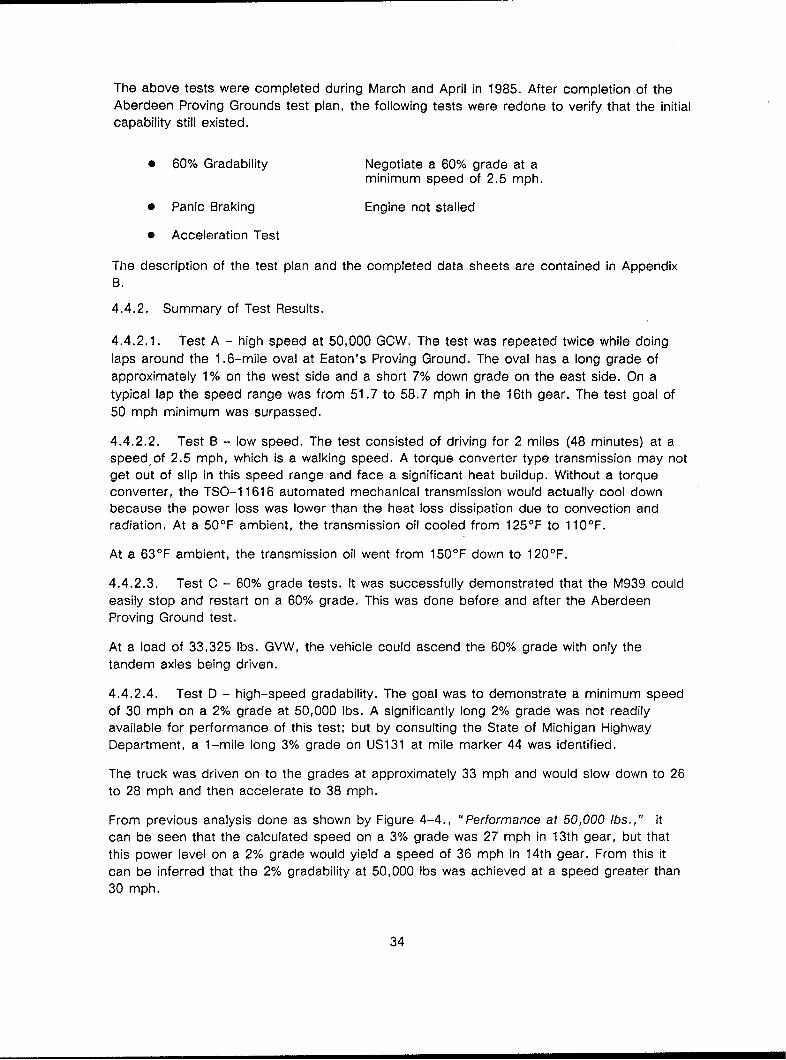
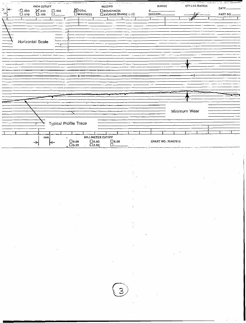
4.6.2.2. Master clutch wear. The wear profile on each cast iron surface was determinedusing a linear profile machine manufactured by Sheffield. The machine was set so that thelength and depth of the profile would be magnified by factors of 10 and 200, respectively.The wear profile was taken radially O.D. to I.D. in four places for each surface. The profileswere then converted by computer to cross sectional wear areas. The average wear wasdetermined by dividing the area by the length of the profile. See the formula below andFigure 4-8.
Profile = a trace of wear using a Sheffield linear profiler
set for magnified scales
Length = length of wear profile
Area = Profile converted to cross sectional wear areaAreaAverage Wear= (length x magnified scale)
The friction discs' pads were measured for thickness using a micrometer while the discswere loaded. The loading more closely simulates actual operating conditions. Pad wear canthen be determined by subtracting pad thickness used from pad thickness new. Table 4-6summarizes master clutch wear.
43

44

Table 4-6. Master Clutch Wear
Cast Iron Surfaces Friction Pads
Average AveragePlate Side Wear Disc Max./Min. Wear
Intermediate Front .0038 New .360
Rear .0037
Front .353/.343 .007/.017
Pressure -- .0047
Rear .371/.359 -. 009*/.001
* The ceramic material used for the friction pads is a type that expands during the
first few applications of the clutch. Pad wear begins after this initial expansion.
45

46

RDRANGE STYLUS RADIUS DAT 2 -rDayonOh
RAGE RNGESS i) DVSON pSO PART NO...__ Sheffiald Measurement Division 45401
vertical Scale
- 0 - 0 -
__________________ Metal
,UTOFrF
08.00 CHART -NO. 70467916
Figure 4-8 Clutch Plate Wear
47
G0

Dayton, Ohio 0 5(, INCH CUTOFF -130RECORD RANGasurement Olvision 45401 -71.603 9-030 0C300 TOTAL ______ES
(:.oIo 0ilbioo 0 - OWAVINESS D AV'ERAGE (RANGE 16) DIVISION-
Horizontal Scale _______________________
00
Typical Profile Trace ________________
mT Wear _______________
mmi0.. MILLIMETER CUTOFF
0008 00.80 0a8.oo CHART N(____~~ 00________ O.25 012.50, 0 -
INCH CUTOFF RECORD RANGE STYLUS RADIUSDATE-
1-0b glc .030 0.300 XcTOTAL EIRO "UGHNESS ______n 0-01o [3_1__ D WAVINESS UJAVERAGE (RANGE- 16) DVSO -PR O
___Horizontal Scale
-0 0
Minimum Wear _______
* - Typical Profile Trace ______________________ ____________
I min - . MILLIMETER CUTOFF0nn10.08 30o.80 08.00 CHART NO. 70467916
I~~~ 1-00.25 02.50f 0 -___- _ _ _

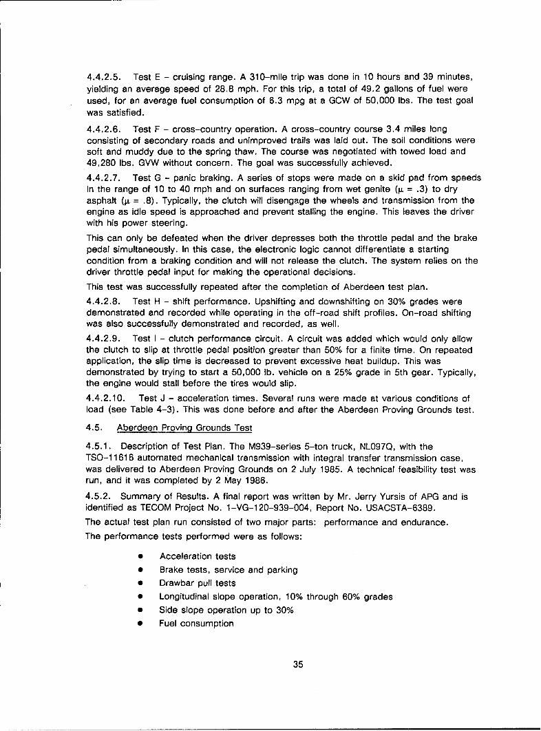
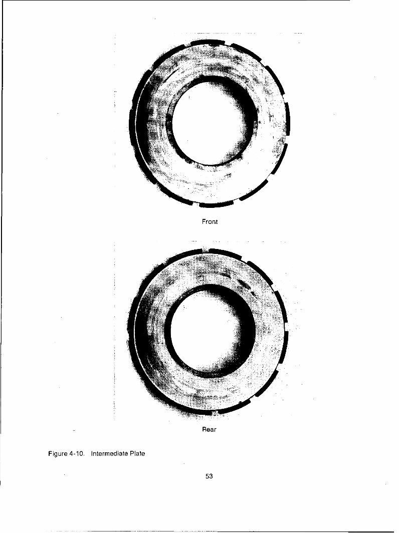
The clutch was reused as is (see Figures 4-9 through 4-11) during the transmission rebuildfor the Modern Technology Demonstration Truck because the wear was found to beminimal. Future wear data will be taken after the new vehicle is tested. This data will help
determine clutch life for this application.
4.6.3. Transmission Mechanical Description. The transmission selected to be adapted tomeet the M-939 performance goals is the TSO-11616 transmission. This is a twincountershaft design with a four-speed plus reverse front box combined with a four-speedSplitter auxiliary section, for a total of 16 speeds.
The twin countershaft transmission design offers more capacity with less length and weightover single layshaft transmissions.
An important feature of Fuller twin countershaft transmissions is the floating mainshaft. Thisallows for a 50/50 torque split between the two countershafts and optimizes their gear life.
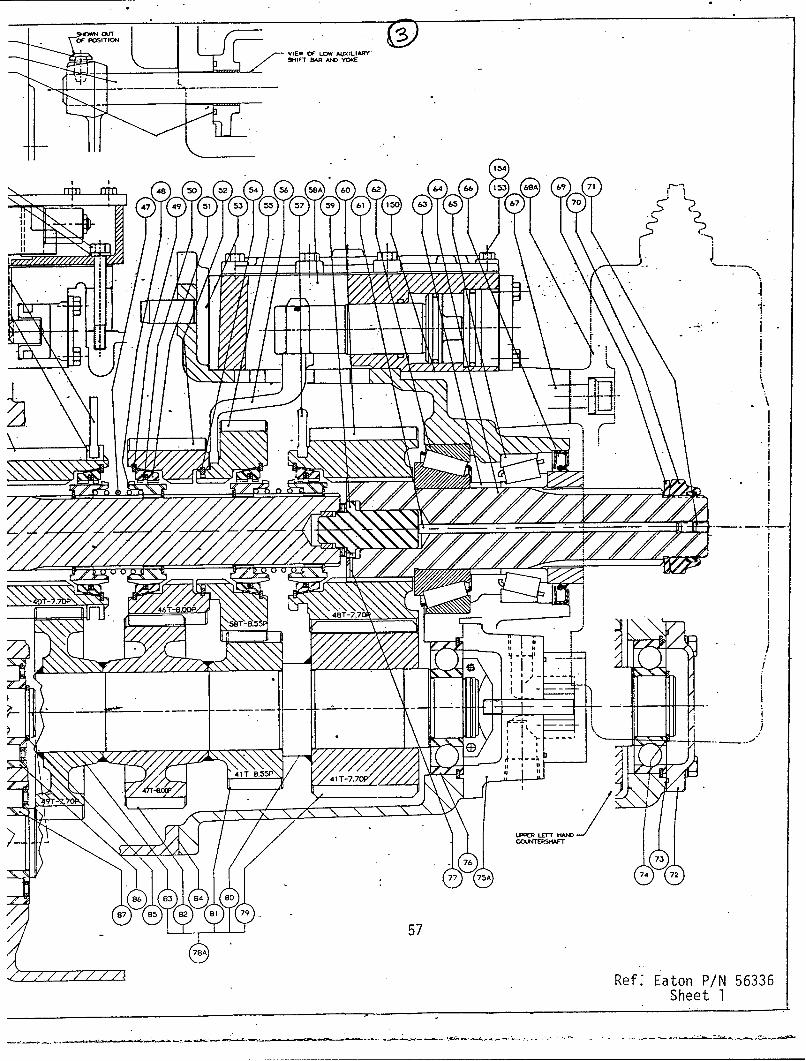
The TSO-1 1616 transmission is defined by the following assembly drawings:
"* 56336-E, Sheet 1, Full-Size Cross-Section of Main and Auxiliary Section(Figure 4-12.)
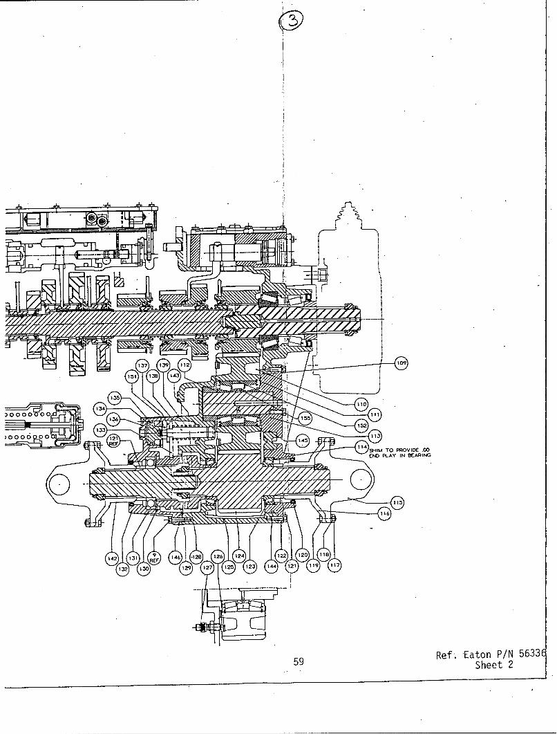
"* 56336-E, Sheet 2, 1/2-Size Cross-Section of Transmission and Integral
Drop Box (Figure 4-13.)
"* 56336-E, Sheet 3, 1/2-Size Exterior View of Transmission (Figure 4-14.)
The TSO-11616 transmission, bearings and shafts are designed for an input torque of1,150 lb-ft. Since in this application the maximum engine torque is only 650 lb-ft. and therated engine rpm is 2100 rpm, the main box gearing and bearing lives were notrecalculated for the lesser inputs.
In order to eliminate the transfer case requirements, an integral drop box was added to theTSO-11616 design. This design drops the output shaft 11.62 inches from the enginecenterline and moves the output over 9.58 inches towards the left side of the vehicle.
This is comparable to the output positions of the existing transfer case, but is located
forward of the original providing better driveline angles and reducing the number ofdrivelines from four to two.
A Curvic Coupling jaw clutch is used to allow the front axle to be disengaged in highwaydriving. An output driven gear pump is added to improve oil circulation and provide headsetlubrication in extended grade operation.
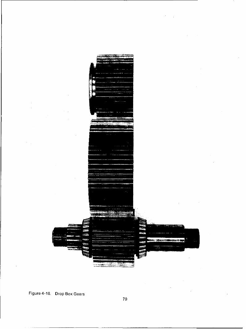
4.6.3.1. Gear inspection. The gears were visually inspected for signs of excessivecompressive stresses. Typical compressive stress problems appear on the teeth in theform of frosting, pitting and spalling. All gears were in excellent condition and did notexhibit any compressive stress problems, as shown in Figures 4-15 through 4-18.
The gears were also magnafluxed and inspected for bending fatigue cracks in the roots ofthe teeth. The overdrive gear on one auxiliary countershaft was found to have nine crackedteeth. Metallurgical analysis determined that the cracks were the result of low to minimumtooth case depth, and core hardness possible produced during the welding process that isused to attach the gears to the countershafts (see Appendix C). The remaining gears werefound to be crack-free. All welds used to attach the gears to the countershafts wereinspected and found to be crack-free.
49

50

Front
RearFigure 4-9. Front Friction Disc
51

52
Front
Rear
Figure 4-10. Intermediate Plate
53

54

Front
Rear
Figure 4-11. Rear Friction Disc
55

56

20 22 6 25 27 29 31 33 33 37 38A 41
19 2 A 23 24 26 28 ;30 32 34 36A 39 40
er
t.r
1.3 AOT9,10.10P
NI T-U29 11
*7.
10406
100 98 9T-359 8
OPENNG oTH IDE 101 99 4 92 90 1

SHOWNOWAL(LIR
45 SHlIFT BAR AND V0OIZ
6 25 27 29 31 33 5a 37 38A 41 43
)E 24 26 28 30 32 T34 36A .39 40 42
r r 48 50 52 54 56) 58A 60 62 64
47 49 51 53 Ss5 57 39 61 150 63
I tt
-. 7
()T-B.00P 6-8 48T-7.7
UTa
I I T-5. 0
1\\ ASP 41 T-704
ST~~ -Ri
-4 Ll57
100 98 95 93 91 89 B
P.T.0.86TH SIDES 101 99 96) 94 92 90 es
97A
POF ITION0 F POSTION LVIEW
OF LOW ALiIXILIAFry
AIF
BAR AM YC* vO.
u -ri~ 4N
-.7
48T-7.7
--- -- -- --- .- - -------- - -- -~I - --.
41T 8.55P' VI-77 41 A
LPPER LEFT IIAJ
- 76 .7
77 75A 74 72
86 83 84 8
87 85 82 8l 79 - -
5778A
Ref.' Eaton P/N 56336Sheet 1

0
Figure 4-13 Transmission andIntegral Drop Box

137 13 1
151 138 4
133
1144
143
132 130 1i?9 127 123 123 144
1237 139~ -128 12 241292
121 128 12 44 (21 19 I
59Rf.Eto3/N531Shee 21

an - 44.14
2-09 37.92
2.5
21.12
2.44
0
29.708
Figure Jt-14 Exterior View of'
Trans ission
61

44.14
-37.92
10..98
1.121
FAPI SI0E159
27-5.122 .50
1.62
325-
-. 17.1
287 16.86 '- 39.0

I ~15.5052.75
I II
I. 148
Ref. Eaton P/N 56336Sheet 3
m 0)
LO U
n - M0 L.
E-
0. U)
0 U
I- -4UA)A - l
EE
X 7
N U)
E-4 0
U) 0 H!U%D0 H N C4 I-
NI 0(1) 'N: z )
cu E H H ~x I m~H C4C 04 1
%D CD, > T H
>) gI, WIH
Z ~ ~ :DZ F4H H U, 1
I II"JO. ~~~ ~l ;!kD7 E-i47iL~ .~L~
.C I I E-- - -q
R R o->
2LC~ HD 1 04 :z U, I p
In- >r4 gr ro u. - o o
C)a kttl r FI ko 0-1 r- D k Lr N6-

%0 0 I'0 EO
C4
f-- ton to r41ACI 4 4f4 -- 400
NN
(NOqm 0E Q! A
inI >
HHzN
E-4 E Oj
(n! z >E -I ~ 040I ci Hn go
OcE
ca m
VIIc'!!
In m! 4n * c, (1 C4t It ..j ml Ln (NH 0
Ln ~ %D 001 m! 0 q C4 L
64

Cl~ ~ 0 )C
ml c rr-4 r-It.0 0 V P!4r4 4
E mm0
HJ r-4r. w'ILA
o N Z
C) fit~
C'J HIi fN -q 4 r-4 LA r-4 .-I r-4 '.0 C4 w -I r-4 -4
rl W In- 4E- t
co
H co mH mI I Hi H~
Q4 c 1I ;7 w) E-4 C4 0 00
Na E l HE -4Cl H
H-f Nj ý 01 C. ý W' ) '~ [4 N ~ ' N 1.4 00*u ZU I) <1c z E-1 H 0
I~HI Z V qn-
NW P4 H, I0 I z N CO r4 0
En U) H; H1 HH~ ~ ~ U ~
1) z
-~:3 P4 H-.i-- -
1.41 Etl w¶ 0. 0 0W.CD CD ' L2 ~ I
-m CO 0
Cl:65> ~ ~ 7

0
E LO
J C I.
I
In
E-4 -n
v m
P 4 1
-6
E-4
0ý 0
z 0
*>z zE4 3E
H P4 0i
z
E~ P 4 E -4
z E- E- A4W
5.4
E- ~U) -
U)E- H rl m
jr-P4 w ý - Utc 4 n L f
E -4 l 0 n 40
0 E-4
rn 0
(CC Q )C 0 H E- H
a- i*
0 0 0H
C) 0 U) -4
H& IV H1 IV H1 H- - ron '-r
z 0 C
LALn
z z CY0 0 C Li
0. LA
H CD coP i
m LA .v0
M CD
H: H %D o H
>4 P4 04. _4
U) U) za4 EE p Hx
A4 mI H F:4 :H W :D-U) C) m H n o ) (4 m C
.GI LA U)
Ui M
o u~~
(A H U U ' ) ~l~ :W r *H
I c tD
a)10 k - r- r- r- r- r- - Cz~I __ _
C __67

cn 0
a- l
E- o
rq~
t~E- i -Ip-
0H
> zE-4I
I
E-1 E- -4
E--4
00. Ez H ri
0i 0 i-
H) C0 0)XL00 0 i 0 E- Q)
, [A w H 0 1
~~Uo
rzi col Ho coi
H - ji c
CH~~ H rrz
0 -W en W! L Dr cu r-e
t E f- r- n n
'cn 771ar- 4 c4o4 4co o ci
Cl1 co ~ '. ~68I

Z U)
0. c (( U) 0
5. IZ E-4Ln w (r U)
0 E z~ 4z~
CA rX LA-
w) N FC4
iLH -
&0 0
*la H, o1 (Nj r-4 (N ( N -4 C4 CN v. '0 r- r-4 r-4
4 E E 0
z z IU
LA fx.~ U) H
z 0 U ) -:H C4 xE- E- P 0
Z E- z m H-
C04 p E- 0 --
U) 4~~4 u I U)
N 1 H I P
*0 H- >4 P 1% U)rHo q) 0 H H N 4 1
v r 4 U) 0 Z 9 U 0a, %~u z* - u
N ~ 0 0 0H H
U) U) E-' I U UN I-C)_~~ 0 .
> H
w w9 w) z9 IE- Ha 0 0 N H u-~ U)E-4 :D -4
z 0r- C3 0 N
cV m
LU 00
ca >I 0 4 00* 0.
Iii -- Ln to r-H D114 0 0M l- ' z q L L) tr kD r-1 O L~o69 t

Nl eq N C4 C4 4 r4 N C1 C4 N N~julI eq
E-4 E-4 E-1 4 E-4 E-4 E-4 E-1 E-i E-1 E- E-4 E-4f PI wrzi~ ~~~~ ~~~ N3 nua W~ Fl ri Ii ri ri ri r r rrco Nu
U) U) U) En U) V) ta ri) En U) En M) r) U)
IN
r4W H
E-4 4 1-4u u U E-4
U) SE-4 U) En En E-
14 C14 N
E Un
04 Z01F4 0
04 E-4
H ;D 0 z
-- T14 ca~ i
F-4 0 %0 r-4 3%- Ms 4 4:q -
0- 4 .~14 Q -U
x 1 z xw H I 1~ 00z z t44 WN C Z, z
H H 14 i4 I N ~ H +-4! 44 -
tD Z-i0 0 0rar W . 0n 4w, '~0 to w) T14 z ow- ta~
00 0
bc w700

c U) Un En (n U) U) U), U) U) U) U)
It) U
rr koc
0..~ " a)m r-
C> o It C'4 r- HCL 0 0 uWmý
H w C I
E4 E
z z
CL - 0-
10. mu zp 0 P4 W
P4r- HH
a4i 0 CD
>4~F a) -- H
N l ~ E z Pr r zI La ' H H H4 3 Z E- H- HWI4
(D - % % , Z U ý: Xt: L
~ r=0 q coU U HA U 0 ZU) E-H
ZC 0 0 iz1x 0 Im z ~0~~~ 0 Hx
r ~0 u
zp H a u wQ H N mU - E4pU I ri cl 0 H - I 0 PI iý
uu>4 014 0 U) ul 0~U
WE
rA.I
C c
00
cc~U -. c cc 00 0C
n- %-k D % or
71

(4 (N (4 (V4 C4(N(
E-4 & E-iE-i E'E--
cn Uc I n l Ui) U) U) Ui) U)m 0 '., J
tU, in I U.(N (N
aq. E t
0 CL0
4. r- - rA r D - -
r- v LU rz
0E0--
X ) > 4 44
-M- P4 03 X 0 -1.0~~~rZ 0 )) w' -
X -4 X E-,4 ,-U)H o1 0I
H4 4) M Ii 0 0cr
0,x r-40 Q '0V m c ra cC) I -i p~ >4 >4
c'0 %o % in W. I~N, rmO U in H H
(N x x z 4~ EnU
0 z
W- Ia E-4
SH H 4 w 9 E-1 X U * uw) 0 ~ U > ) ul U) -4 >ý 4
0 0 t3 P0 vz 0u~m 0 0 U U U cU
in nl I -t ~ U ~
WC~inin
%D _r o -4[4 -4aON m ON_ _ '72t k bGoý; %

Figure 4-15, Front Mainshaft Geairs

74

Figure 4-16. Auxiliary Mainshaft Gears
75

76

:I'
-A
!i •M~iw
Figure4-17.Countrshaf Gear
• :,:,it 7

78
i"i
Figure 4-18. Drop Box Gears
79

80
The drop box gears were shotpeened before testing in order to impart a residualcompressive stress in the roots of the teeth. This operation historically extends gear life inbending and was deemed necessary because of the duty cycle required (gear set transfersall loads from transmission to axles). The gears were submitted to Eaton's metallurgicaldepartment for conformation of residual compressive stress. A Fastress machine was usedto measure the stresses before and after testing. It was determined that the gears exhibithigh compressive stresses at the surface (see Appendices D and E).
4.6.3.2. Bearing inspection. All bearings were cleaned and found to be in good conditionwith two exceptions.
A needle thrust bearing had failed during the test due to the transmission's mainshaft beingout of adjustment, causing a preload on the bearing. Installation of a new bearing andproper mainshaft adjustment will correct the problem.
The other problem bearing was a ball bearing used to support the drop box's frontdriveshaft. Although no failure occurred during the Aberdeen test, the bearing failed twiceduring Eaton's testing. Both times the cage that holds and positions the balls failed. Thecause of the failure was attributed to excessive thrust from the driveline. A spherical rollerbearing was chosen as a replacement. The bearing has 10 times the calculated life of theoriginal ball bearing, and installation requires only a minor housing modification.
4.6.3.3. Dog clutches. The dog clutches were measured for wear. The type and amountof wear was found to be typical of Eaton transmissions with dog clutches. The clutchescould be reused but were replaced since the parts are standard stock items and readilyavailable. A description of the type and amount of wear follows.
"* The 3-4 dog clutch teeth were worn on drive and coast side of both ends. The
type of wear was rounding of the ends of the teeth, and the mount was .060inches (see Figure 4-19E).
"* The 1-2 dog clutch teeth were worn on the drive side of the first gear end. Thetype of wear was a rounding of the ends of the teeth, and the amount of wearwas .050 inches (see Figure 4-19G).
* The teeth on the reverse dog clutch exhibited no wear (see Figure 4-19D).
* The teeth on the low dog clutch were rounded .03 inches on both drive andcoast side (see Figure 4-19C).
e The teeth on the intermediate dog clutch were rounded .04 inches on bothdrive and coast side (see Figure 4-19B).
e The overdrive dog clutch teeth were rounded to .04 inches, and the wearextends along the tooth .10 inch on both drive and coast sides (see Figure4-19A).
e The direct dog clutch teeth are rounded by .04 inches on both drive and coastside. Wear extends .125 inches along tooth (see Figure 4-19F).
4.6.3.4 . Front drive clutch. Inspection of the curvic coupling revealed no wear or distressof any kind. This hardware is currently used in Eaton tandem drive axles for heavy-dutytrucks and worked well in this application.
81

82

A B C D
FG
Figure 4-19. Dog Clutches83

84
4.6.3.5. Shift forks. The transmission's shift forks were magnafluxed and checked forcracks. All forks were found to be crack-free except the fork that is used to engage frontwheel drive. The cracks were on the left finger and are of the heat check variety (seeFigure 4-20.). The heating and associated cracks were probably the result of the frontdrive bearing's failure because lack of bearing support would allow extreme misalignmentand thrust loads on the fork.
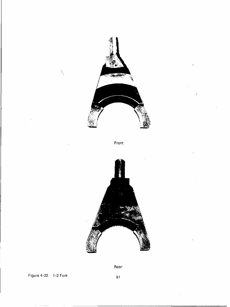
The forks were also measured for pad wear. A review of Table 4-7 shows high pad wear(note .050 maximum wear allowed) on the 3-4 fork, as well as the front wheel drive fork(see Figures 4-20 and 4-21). The remaining forks exhibit minimal wear on the heat treatedpads (see Figures 4-22 through 4-25). Replacement of the front wheel drive fork becauseof excessive pad wear and heat cracks and the 3-4 fork because of pad wear is deemednecessary.
4.6.4. Parking Brake Description. A parking brake is optional on the TSO-1 1616automated mechanical transmission. The assembly is supplied by Auto SpecialtiesManufacturing Company (AUSCO) of St. Joseph, Michigan. It is mounted high on the rearface of the transmission on an extension of the normal output shaft. In this location, thebrake is above the driveshafts, between the frame rails.
The internal components of the brake (actuating discs, friction materials, etc.) are standard11 - by 8 - inch disc components made by AUSCO. The brake design incorporates adegree of self-actuation which allows more braking capacity than a drum brake ofcomparable size. Self-actuation is provided by actuating discs which are separated by ballson inclined seats (ramps). As the actuating discs are applied (rotated in oppositedirections), the balls roll up the ramps, separating the discs to absorb running clearance.This allows the actuating disc to contact the friction discs which are attached to the outputshaft extension. Once in contact, any load on the friction discs is applied through the ballramps back to the actuating disc to provide self-actuation. In addition, the design providesease of adjustment and the ability for both mechanical or automatic actuation in the samepackage.
The brake has sufficient capacity to hold a 35,000-pound vehicle on a 60% grade with 969pounds of pull on the actuating rod. This is accomplished with four disc plates, each withfriction surfaces measuring 11 inches outer diameter and 8 inches inner diameter.
4.6.5. Parking Brake Inspection. The Auto Specialties parking brake was disassembled andchecked for wear. An AUSCO representative was available to discuss the condition of thebrake.
The overall condition of the brake was found to be good with the exception of the frictionplate splines-and their mating adapter hub. The splines on the plates and hub exhibitedextreme material deformation on both the drive and coast side of the teeth. This wasbelieved to be caused by the high speeds and torsional loads present. The AUSCOrepresentative stated that the combination of loads and speeds is not typical for this modelbrake. He recommended change in material from 1017 steel to 1030 steel and inductionhardening of the plate spline along with carbonitriding the teeth on the adapter hub.
Another area of concern was some spalling of the friction material. The AUSCOrepresentative stated that 2% of the discs may have localized spalling due to a "weakinterface structure." This would not, however, affect performance. See Appendix F forbrake inspection report by AUSCO.
85

Table 4-7. Fork Wear*
Left Pad Right PadFork 1 2 3** 1 2 3**
1-2 .000 .002 .005 .002 .002 .005
3-4 .034 .045 .045 .020 .033 .038
Reverse .000 .000 .002 .000 .000 .002
Low .013 .016 .016 .008 .009 .009
Int.-O.D. .007 .008 .009 .010 .013 .016
Direct .011 -- .019 .013 .015 .018
Front Wheel
Drive -- .020 -- -- .012
*Wear values are an average of the measurements taken.
• * Measurement 1 taken 9/19/85
Measurement 2 taken 2/19/86
Measurement 3 taken 6/36/86
86

Front
Rear
Figure 4-20. Front Wheel Drive Fork
87

88

Front
RearFigure 4-21. 3-4 Fork
89

90
Front
Rear
Figure 4-22. 1-2 Fork 91
92

Front
RearFigure 4-23. Low Fork
93

94

Front
RearFigure 4-24. Intermediate-Overdrive Fork
.95

96

Front
RearFigure 4-25. Direct Fork
97

98

4.6.6. Main Box Air Shifter Description. The main box shifter is used to select the propermain section gear ratio. In effect, it replaces the driver's muscle. Mounted on top of theshifter assembly is an air valve manifold assembly which operates the shifter and other
devices. A longitudinal cross section through the shifter and manifold is shown as Figure4-26. A transverse cross section of the shifter is shown in Figure 4-27, which illustratesthe piston and shift yoke arrangement.
The air shifter assembly uses three shift pistons to engage the five main box gear ratios.Two pistons are double acting and one is single acting. A set of interlock pins between thedifferent piston shafts prevents simultaneous engagements of more than one gear. This isan important requirement in any mechanical gear box shift mechanism.
The shift pistons are returned to the neutral position by air-operated neutral pistons. Theair supply to both the neutral pistons and the shift pistons are through solenoid-operatedthree-way valves in valve manifold. In the event of a loss of power to the shifter whileunderway, the shifter would remain in the selected gear. If springs were used instead ofneutral air pistons, the shifter would be forced neutral in the loss of electrical power.
Another feature of the air shifter is that it uses a cross-shaft contacting each air piston to
sense when the main box is in neutral. This shaft activates a switch to provide thefeedback to the electronic controller. Sensing neutral is an important action in the shiftsequencing.
The shift yokes are allowed limited rotation in the shift piston at their point of attachment.This allows the shift yoke to accommodate some slight misalignment between thetransmission mainshaft and the shifter housing.
4.6.7. Main Box Air Shifter Inspection. The shifter was disassembled and checked forwear of the mechanical hardware and deterioration of electrical components. The shifterdid not require any rework and, therefore, was just reassembled. It was cycled on thebench to check for function and to detect any air leaks before being attached to thetransmission.
4.6.8. Auxiliary Box Air Shifter Description. The construction, actuation and operationrequirements of the auxiliary box air shifter are basically the same as the requirements ofthe front box air shifter.
It uses three shift piston shafter for the four gear ratios, plus neutral. The piston shafts arereturned to neutral by air pressure. Of the three shift pistons, one is used in two directionsfor intermediate and overdrive gears, while the pistons for low and direct stroke in onedirection only. The air shifter for the auxiliary has been designed specifically for thisapplication.
The shafts have a mechanical interlock to assure that multiple gear selections cannot be
made, and a switch is activated when the auxiliary section is in neutral.
The four-solenoid operated, three-way insert air valves required to operate the auxiliaryshifter are integral to the assembly. This optimizes the air valve performance.
Testing has indicated the importance of both sufficient force as well as flow capacity toshift fast for off-road mobility.
4.6.9. Auxiliary Box Air Shifter Inspection. The mechanical components of the shifter werefound to be in good condition. Following disassembly all of the O-ring seals werefunctioning properly. The solenoid-operated valves were function tested. The shifter wasreassembled and checked for air leaks and proper operation.
99

UL
&w I--
o _
o 0
II-
tw
0 00
j~ C ,
0
ILI U) z
' __ _
0 w
j -w
I0-0 U
w
10
Waa
zzZ'.00
1000

Figure 4-27 Main Box Air Shifter Fork Arrangements
101

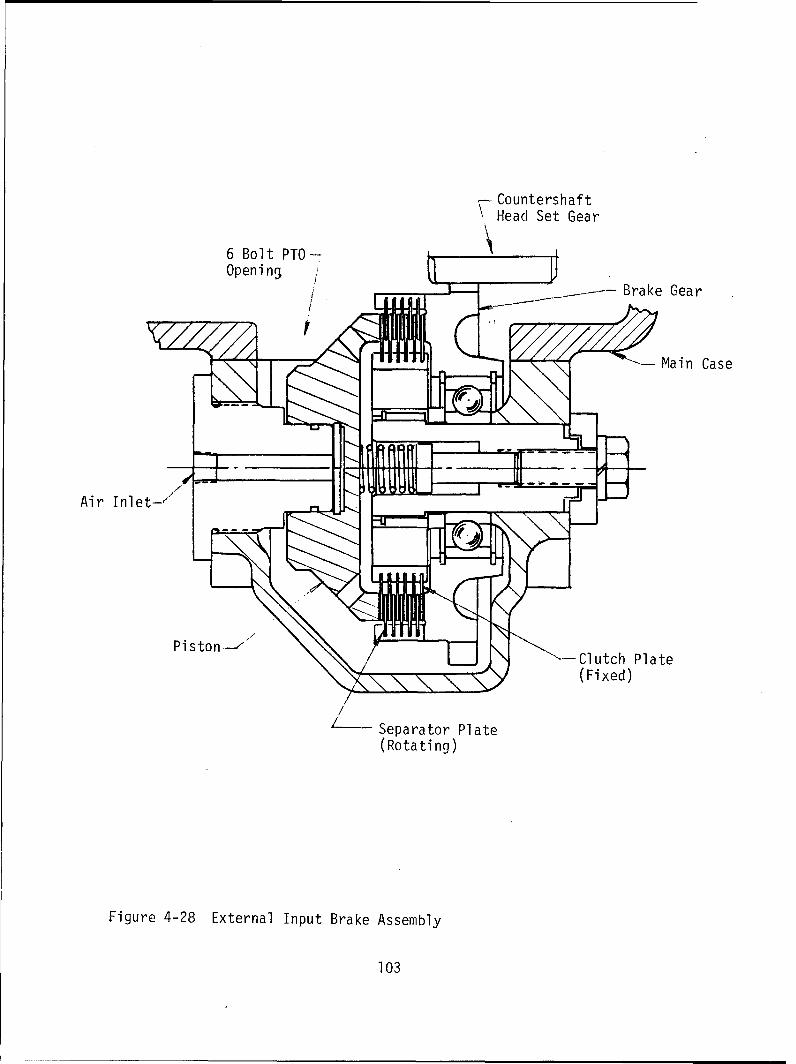
4.6.10. Input Brake Description. The input brake is used to slow down the transmissioninput gearing and the clutch-driven discs during shift synchronization. When the input isrotating faster than the required speed for synchronous dog clutch insertion, the brake isapplied momentarily to slow it down.
The brake assembly being used is normally mounted on the six-bolt PTO pad on the rightside of the transmission (see Figure 4-28). Hardware is available to adapt the brakeassembly to the bottom eight-bolt PTO pad.
The input brake is a multiple-plate design actuated by air pressure. The gear in the brakeassembly meshes with the headset countershaft gear and thereby with the Input section ofthe transmission. When air is applied, the input gearing is grounded to the transmissioncase, causing the brake action.
The normal transmission oil flows in and around the brake assembly.
The air piston force and number of active surfaces are sized to give a deacceleration rateof 3,000 to 4,000 RPM/second measured at the input shaft.
In order to achieve the very fast on-and-off characteristics required for fast shifting inoff-road conditions, a pilot-actuated valve has been mounted directly to the brakeassembly. The solenoid valve in the air valve manifold has only to provide the pilot signal toactivate the integral valve. This has reduced the actuation time by 63% in reducing theresponse time from 0.08 seconds to 0.03 seconds.
The brake is activated by the logic when the clutch is disengaged and the splitter section isin neutral. The brake turn-off time is determined by means of a lead circuit which sensesthe synchronization error and the rate of change of input speed in order to have the brakefully off before the jaw clutch in the auxiliary section makes engagement. If the brake is notdeactivated soon enough, it creates a retarding force which is significant and noticeable Inthe lower gears.
4.6.11. Input brake Inspection. The plates were checked for wear and or any distress dueto high temperatures.
The friction plates' material exhibited signs of use when compared to new plates, but werenot worn enough to require replacement. The steel separator plates were like new and didnot exhibit any signs of being exposed to high temperatures. No problems were found withthe spline teeth on any plates. Both sets of plates can be used for reassembly.
4.7. Rebuild for Modern Technology Demonstration Truck
4.7.1. Mechanical System. The unit was rebuilt using most of the original test parts. Allparts that were reused were inspected, deemed to be sound, and exhibited no more thanminor use.
The parts that were replaced could be placed in three categories: routine (a goodpractice), upgrades, and refinements.
4.7.1.1. New drop box gearing. The replacement of the drop box gearing could beconsidered a refinement since the only change from the original gearing was to use gearswith modified tooth profiles in order to apply the latest noise control technology.
102
- Countershaft
Head Set Gear
6 Bolt PTO-
Open i ng) /
--- Brake Gear
Main Case
Air Inlet-,
Ps-Clutch Plate(Fixed)
L• Separator Plate(Rotating)
Figure 4-28 External Input Brake Assembly
103

4.7.1.2. Production transmission housing. Another refinement was to replace the maintransmission housing with the production housing. This new housing also allows the upshiftbrake to be mounted internally on the bottom. This eliminates the external side-mountedbrake which interfered with the truck's frame rail and was extremely time consuming toinstall.
4.7.1.3. Mainshaft locking spline. A step lock spline was incorporated between the directdog plutch and the direct mainshaft gear. This spline is required to aid in elimination of the3rd gear kick-out problem that occurred while climbing the 29% grade on Churchville I'B."The splines are shown in Figure 4-29.
4.7.1.4. Front drive bearing. The ball bearing that supports the drop box's front driveshaft needed to be upgraded. It failed twice during Eaton's testing but never during theAberdeen test. A spherical roller bearing was the chosen upgrade. The new bearing has 10times the calculated life of the old bearing and should provide more than adequateperformance.
4.7.1.5. Additional components. A number of new components were added to meet therequirements of a single point for actuator exhaust, supply air, and oil cooler lines. Thisrequirement was part of the stand-alone power pack design. A single air exhaust manifoldwas fabricated and installed (see Figure 4-30).
4.7.1.6. Dog clutches. Parts were replaced as a matter of good practice since sparehardware was available.
4.7.2. Improved Acceleration Times. Zero to thirty MPH acceleration data was taken onboth the microprocessor version of military AMT controller as well as the hybrid version.This data is also compared to test data for an Allison equipped vehicle (see Table 4-8).
Two sets of data are shown for the microprocessor version due to two different shiftalgorithms being used. Eaton Micro 1 did not allow as many multiple upshifts as did theEaton Micro 2 tests. It should be noted that the Eaton Hybrid controller did not allow anymultiple shifts.
The Micro 1 version has been selected as the overall best performance algorithm despitethe faster acceleration times seen in the Micro 2 version.
The Eaton microprocessor version can be seen to accelerate from zero to thirty at least1.7 seconds faster than the Eaton Hybrid version. If Micro 2 data is used, thenmicroprocessor version would be 2.4 seconds faster.
4.7.3. Electronic Control System. The electronic control system (ECU) for the AutomatedMechanical Transmission automatically performs all of the functions to operate the mainclutch and shift the TSO-11616 transmission. In the previous ECU, the control functionswere implemented using a combination of analog and digital logic circuits to processinformation from the input sensors to control the output actuators. This "hybrid" ECU hasbeen replaced by an Mkl ECU which employs two 16-bit microprocessors to perform thesame functions as the previous system with several significant performance enhancements.In addition to providing these performance enhancements, the microprocessor-based MklECU uses fewer electronic components with more ruggedized construction in a newimmersible package with military connectors.
104

Figure 4-29. Locking Spline
105

106
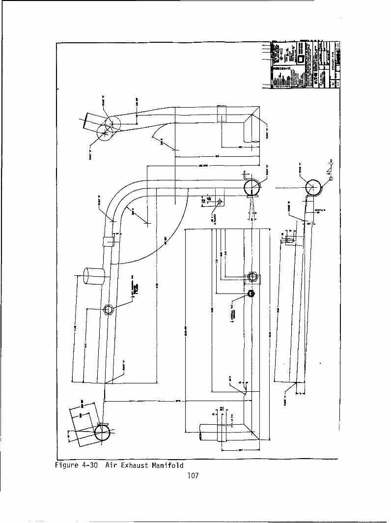
AJ. ill,
It
NMI
ini
Figure 4-30 Air Exhaust Manifold
107
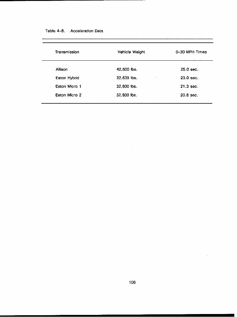
Table 4-8. Acceleration Data
Transmission Vehicle Weight 0-30 MPH Times
Allison 42,600 lbs. 25.0 sec.
Eaton Hybrid 32.639 lbs. 23.0 sec.
Eaton Micro 1 32,600 lbs. 21.3 sec.
Eaton Micro 2 32,600 lbs. 20.6 sec.
1108
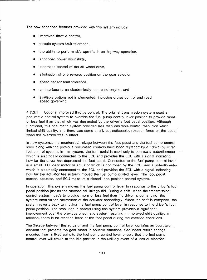
The new enhanced features provided with this system include:
"• improved throttle control,
"* throttle system fault tolerance,
"* the ability to perform skip upshifts in on-highway operation,
"* enhanced power downshifts,
"* automatic control of the all-wheel drive,
"* elimination of one reverse position on the gear selector
"* speed sensor fault tolerance,
"* an interface to an electronically controlled engine, and
"* available options not implemented, including cruise control and roadspeed governing.
4.7.3.1. Optional improved throttle control. The original transmission system used apneumatic control system to override the fuel pump control lever position to provide moreor less fuel than that which was demanded by the driver's foot pedal position. Althoughfunctional, this pneumatic system provided less than desirable control resolution whichlimited shift quality, and there was some small, but noticeable, reaction force on the pedalwhen the override was in effect.
In new systems, the mechanical linkage between the foot pedal and the fuel pump controllever along with the previous pneumatic controls have been replaced by a "drive-by-wire"fuel control system. In this system, the foot pedal is used only to operate a potentiometerwhich is electrically connected to the ECU and provides the ECU with a signal indicatinghow far the driver has depressed the foot pedal. Connected to the fuel pump control leveris a small D.C. gear motor or actuator which is controlled by the ECU, and a potentiometerwhich is electrically connected to the ECU and provides the ECU with a signal indicatinghow far the actuator has actually moved the fuel pump control lever. The foot pedalsensor, actuator, and ECU make up a closed-loop position control system.
In operation, this system moves the fuel pump control lever in response to the driver's footpedal position just as the mechanical linkage did. During a shift, when the transmissioncontrol system needs to provide more or less fuel than the driver is demanding, thesystem controls the movement of the actuator accordingly. When the shift is complete, thesystem reverts back to moving the fuel pump control lever in response to the driver's footpedal position. The resolution in control using this system provides a significantimprovement over the previous pneumatic system resulting in improved shift quality. Inaddition, there is no reaction force at the foot pedal during the override conditions.
The linkage between the actuator and the fuel pump control lever contains an overtravelelement that protects the gear motor in abusive situations. Redundant return springsmounted from a fixed point to the fuel pump control lever ensure that the fuel pumpcontrol lever will return to the idle position in the unlikely event of a loss of electrical
109

power. The foot pedal sensor includes redundant return springs to provide a firm, but notstrenuous, pedal force.
For the Modern Technology Demonstration truck, this optional throttle control was not used,
as a direct electronic link as described in section 4.7.3.8. was used.
4.7.3.2. Throttle fault tolerance. The inclusion of the "drive-by-wire" fuel control resultsin a system where the engine fueling, clutch torque and transmission operation is under thecontrol of an ECU. To prevent the occurrence of a hazardous situation in the event of amalfunction in any part of the electronic controls, a significant effort was made to make thesystem failsafe and fault tolerant.
A safety switch is included in the fuel pump control actuator which provides a signal whichis electrically independent of the feedback potentiometer that indicates that the fuel pumpcontrol lever is in the idle position. If the system is commanding the fuel pump to be at theidle position, and either the switch or the feedback pot imply that the idle position has not
been reached, then the system de-energizes the fuel shut-off solenoid, which turns offfuel to the engine.
Two safety switches are included in the foot pedal sensor. The throttle set (THS) switchindicates that the driver has his foot on the pedal and a second switch Indicates that thedriver has depressed the pedal all the way through a "ride-through detent" (RTD) and isrequesting full fuel. The state of these two switches is continuously monitored andcompared with the information received from the pedal position sensor. If the informationdoes not agree, a failsafe condition of bringing the fuel pump control lever to its idleposition is enforced.
4.7.3.3. Skip upshifts. The TSO-11616 transmission has 16 forward gear ratios. The newsystem retains the ability to select different starting gears by selecting one of three drivepositions on the gear selector. D1 (Drive 1) selects 1st gear as the starting gear, D2 (Drive2) selects 3rd, and D (Drive) selects 5th. The D (Drive) position is used in the lessdemanding driving situations. In these situations, the small gear steps available in this16-speed transmission should be shifted by one or two gears in these cases. This controlenhancement eliminates much of the unrequired shifting in the lower gears, which results ina smoother and faster acceleration of the vehicle. If the load on the vehicle increases, thesystem will upshift by one or two gears automatically as the situation requires.
4.7.3.4. Power downshifts. In off-road driving, one often encounters a situation in whicha steep grade is encountered and the transmission is required to downshift by severalgears to pull the grade. In the previous system, the transmission would downshiftsequentially two gears at a time as the vehicle speed decreased on the grade. As a result,because of the number of shifts made and the fact that torque is interrupted during a shift,the vehicle speed would often decrease below that speed at which the vehicle was powerlimited.
The utilization of microprocessor technology allows more intelligent shift decision strategiesto be implemented. The enhanced power downshift strategies implemented in this systemuse vehicle deceleration to anticipate the gear required to pull the grade. The new systemautomatically makes fewer shifts of larger steps as required, thereby decreasing theamount of time spent shifting, resulting in higher average vehicle speeds in these situationsthan was capable with the previous system.
110

4.7.3.5. All-wheel drive control. In operation, it was found that many inexperienceddrivers did not know under what circumstances they needed to engage the all-wheel driveuntil they were well into the conditions where they needed it. When it became apparent tothe drivers that they needed the all-wheel drive engaged, they would engage it under hightorque conditions which, in doing so, would deliver a near damaging shock to the driveline.Virtually all drivers knew to select one of the off-road drive ranges, either D2 or Dl, wellin advance of its need.
To minimize the situations where the all-wheel drive is engaged under high torqueconditions, the new system automatically engages the all-wheel drive whenever one of theoff-road drive ranges is selected. This "automatic" feature makes the vehicle easier todrive since the all-wheel drive is engaged before you need it and reduces the potential fordamaging the driveline.
4.7.3.6. Single reverse selection. The previous system had two reverse gear selectorpositions to select one of two reverse gear ratios. The new system automatically selectsthe reverse gear ratio based upon the last used drive position. The least reduction reversegear is selected if the last drive position was D (Drive) which is used in on-highway driving.The greatest reduction reverse gear is selected if the last drive position was DL (DriveLow) or D2 (Drive 2) which are used in off-road driving.
4.7.3.7. Speed sensor fault tolerance. Control of the transmission is based uponinformation derived from sensors monitoring the speed of the engine, transmission inputshaft, and transmission output shaft. Peak performance of the system can only be obtainedwhen all three of these sensors are functioning properly. In the previous system, theinformation from these sensors was continuously checked for validity. If the informationfrom any sensor was found to be invalid, all shifts were inhibited, and the vehicle wasallowed to operate in the present gear until it came to a stop.
The new system continuously monitors the validity of the information from the sensors, asdid the previous system; however,in the event that the information is found to be invalid,the new system replaces the invalid data with best estimates based upon informationreceived from the valid sensors. As a result, the transmission system remains operational,albeit with reduced performance, with any single-point speed sensor failure. Asimultaneous failure of two or more speed sensors will result in the system inhibiting allshifts as in the previous system.
4.7.3.8. Electronic engine control interface. An interface to an electronic engine controlsystem has been designed and implemented in the transmission control unit. This interfaceprovides a Pulse Width Modulated (PWM) signal which can be connected to an auxiliarythrottle input on a John Deere engine electronic control unit. The foot pedal sensornormally used with this electronically controlled engine is not used. The foot pedal sensorused by the transmission system remains connected to the transmission control unit. Thetransmission control unit then provides all throttle inputs to the engine controller throughthis interface. The D.C. gear motor actuator normally used with this transmission systemwith mechanical fuel pumps as described in 4.7.3.2. is not required.
A second electronic interface with the engine is also provided to allow the transmission toselect one of two torque curves. This interface is used by the transmission to select a level
111

of engine torque based upon the transmission reduction ratio that will be safely handled bythe rest of the driveline when multiplied by the transmission gear ratio.
4.7.3.9. Available options. The use of a drive-by-wire fuel control allows additionalfeatures of the transmission system to be available as options. These options, which areimplemented in the commercial counterpart of this transmission system, include cruisecontrol and road speed governing.
Cruise Control is a speed control system available as an option on this transmission. CruiseControl maintains a constant forward speed during most highway and some off-road drivingwithout the driver keeping his foot on the accelerator pedal, thus increasing driving comforton long trips.
Road Speed Governing is also available as an option on this transmission. Road SpeedGoverning limits the top speed of the vehicle independent of the engine governor andvehicle gearing. The top speed limit is preset at the factory and cannot be changed by the
user. The Road Speed Governor allows the vehicle to be geared in a "gear fast, run slow"configuration for improved fuel economy in on-highway operation and provides theassurance, by design, that the vehicle will not be operated at unsafe or fuel-inefficientspeeds.
112

SELECTED BIBLIOGRAPHY
Holmes, R. C. "Analysis of Mainshaft Failure in Eaton TSO-11616 Transmission," Eaton CoRD -Detroit Center Technical Report No. 86011, 1986.
Holmes, R. C. "Description of the Construction and Operation of an Automated MechanicalTransmission," Eaton CoRD - Detroit Center Technical Report No. 83067, 1983, for contractDAAE07-82-C-4121.
Olson, 0. "Evaluation Study and Preliminary Truck Testing of an Automatic Control System Concept
for a Mechanical Transmission," Eaton CoRD - Detroit Center Technical Report No. 82085,1982, for contract DAAE07-81-C-4054.
Spicer Angle-Spring Clutch Parts List C100-ASP, 1981.
Yursis, G. "Final Report Technical Feasibility Test of Eaton TS011616 Transmission Modified forM939 Series Trucks," Report No. USACSTA-6389.
113


APPENDIX A
PRODUCT LITERATURE AND OPERATION
OF THE
EATON FULLER "CEEMAT T M." TRANSMISSION
A-1

EATON FULLER CEEMAT" TRANSMISSION
INTRODUCTION
Eaton Corporation has invested in developing automated mechanical transmissions withautomated conventional dry clutches for its existing markets of commercial trucks in normalon-road applications.
In this contract with TACOM, the feasibility of applying this development towards the on-offroad requirement of military tactical trucks was evaluated with reasonable success inreaching both the performance and durability goals.
The traditional approach in automatic transmissions has utilized a hydrokinetic device, fluidcoupling or torque converter, as the coupling between the gearbox and the engineflywheel. The success of this approach is well known, and its use in construction, on-offroad, military and start-and-stop applications well documented.
As a business as well as a technical decision, Eaton Corporation has decided to competein these same applications with a torque converter between the automatic mechanicaltransmission and the engine flywheel. The transmission model is calledCEEMAT-" Converter Enhanced Electronically Managed Automatic Transmission."Production of the CEEMAT transmission will begin in September 1988 for application in frontdischarge mixers (concrete). A detailed decription of the transmission follows.
TECHNICAL DESCRIPTION
The design strategy was to select one of Fuller's line of manual transmissions intended foron and off highway service and to automate it.
In view of the fact that the Roadranger transmission is not used in military vehicles yet, andthat its most distinguishing feature, its twin countershaft design, is not familiar to mostreaders, we have included some basic information on this transmission from Eaton's salesand service literature. The next page is a current sales brochure illustrating the essentialfeatures of the 9-speed, on-off series. This series includes the one used as the nucleus ofthe CE2MAT. The suffix "B" denotes an extended range of gear ratios for off-roadapplications. Note that, for this transmission series, the overall ratio coverage is17.21 [12.56 (low) * 0.73 (high)]. This single range of nine forward gears has neverbefore been available to military vehicles. We would also mention here that theRoadranger series has acquired a thirty-year history of dependability in commericalapplications all over the world. There are now 1.1 million of them in services, of which250,000 are nine-speeds.
Following the brochure are two pages of excerpts from one of Eaton's service manuals. Atthe top of the first page is a view of the transmission, showing the twin countershaftsflanking the mainshaft. This design was developed as a method of reducing the length ofthe transmission, but it also contributes much to the transmission's extraordinaryperformance and durability. Following this view is a description of how driveline power istransmitted through the countershaft arrangement. Material such as this is immediatelyavailable to the Army for training its mechanics on the CE2MAT.
A-2

Product Literature CEEMATFUL-205-RO
Eaton® Fuller®TransmissionsCEEM AT Converter-Enhanced Electronically Managed Automatic Transmissions
The heavy-duty automatics witha Roadranger heritage.
Features
-Proven Roadranger Transmis-sion performance capable ofhandling various engines up to475 hp and 1450 lbs.-ft. torque.*
-Offers state-of-the-art electronic. ..-.technology with the reliability ofthe Roadranger twin counter-shaft design.
-Broad ratio coverage and micro-computers combine for smooth,progressive shifts made auto-matically.
-Ratio coverage enhances off-road performance and reducesexternal cooling requirements.
-Roadranger-based modulardesign for ease of maintenanceas well as operation. Electronicrepairs can be done in-frame.
-Spline driven torque convertereliminates costly installationprocedures.
Notice: This is an "early release" sales sheet. Specifications, ratios"600 HP and 1650 Lbs.-Ft. with approval. and capacities are subject to change at any time without notice.
TN A-3

Eaton Fuller CEEMATRoadranger Transmission Specifications.
CEEMAT SPECIFICATIONS: RTO-9109B-AT RTO-121098-AT RTO-14109B-AT Gear Ratio % Step
Rating Nominal Power Rating 300 HP 370 HP 475 HP 9 .73Input Speed, Full Load 2800 RPM 2400 RPM 2400 RPM 37(Governed) 8 1.00 38Nominal Torque Rating 975 Lbs.-Ft. 1250 Lbs.-Ft. 1450 Lbs.-Ft.* 7 1.38
41Mounting Engine SAE#2 Housing SAE#1 Housing 6 1.95
One Vertical Mtg. One Vertical Mtg. 43Pad Each Side Pad Each Side 5 2.79
37Torque Type Single Stage, 3 Element, 2 Phase 4 3.83Converter 38
3 5.28Stall Torque Ratio 2.2:1 41
2 7.47Oil Oil Type Mil L-2104D C3 Type Fluids/Grade lOW 68System Filtration Integral, High Pressure Filter 1 12.56
Pressure Lube Gear Driven @ 1.18 X Engine Speed Rev 13.14
Capacity 9 gals. 10 gals. 11 gals.
Size Length- 35.9 in. 36.4 in. 37.0 in.
Weight (Approx.) 1000 Lbs. 1020 Lbs. 1040 Lbs.
Applications to 600 HP and 1650 Lbs.-Ft. available with engineering approval.SAE flange to end of output shaft spline.
0 10 20 30 40 50 60 65 MPH
2100 RPM -- L
Peak Torque1300 RPM
Eaton Roadranger service keeps you on the road.
For more information contact your regional Eaton Roadranger sales and service officeat 1-800-TCM-HELP. In Canada, call 1-800-387-3935.
For more information on all Eaton Fuller Transmission products, contact: Eaton CorporationTransmission DivisionP.O. Box 40131F -4 •Kalamazoo, MI 49003(616) 342-3344
FUL-205-RO 4/88

Prodct Lteraure TX/RO-1 609FUL10-R RX/RO- 209
.......- 46-9B
Eprovn Fullerger Transmissions0 pt
ngf0ruietr-
* i9e ~ *
S. Q
~sytei feture corrsion
reisan rag aiaveadfitr
reg atrone dietyo
.sitn 94 X
Wrdiv mode us e diec shf
patter
No spca -- ol or triigr5 u
or 5 mainthanc
* a: S 01

Eaton Fuller, RTX-1 160913, RTX-1 2609B3, RTX-1 4609BRoadranger Transmission Specifications.
.v~~~. V ~ T)1BRX460§B~ P ls noin/mSpeeds:k9 forward, 2 reverse. 4~ Gear Ratio % Step ~. Fuel
7 ~ Capacity: 15fbs-t8 .73 RangeRTX- 1 609B -up to 370 hp, 115 7b.t 130
q. torque,. 10V ~ RTX-12609B -up to 370hp, 1200 lbs.-ft. 38torque, 6 1.38RTX-1 4609B -- to 450hp. 1450 lbs.-ft. 4torque. 5 ý1.95
432Weight: (less clutch housing) 4 2.79RTX-1 1609B - 590 lbs. 33.8RTX-1 2609B -602 fbs. 38.8RTX- 4609B - 616 lbs.
Length:2 5.28 4RTX-1 1609B -28.9 in. 1 .7 68RTX-1 26098 - 28.9 in.Lw 125RTX-1 4609B - 29.5 in.
H iPower Take-Off Openings: Reverse 342 SAE standard openings.Right side, regular-duty, 6-bolt. Lo 3.4Bottom, heavy-duly, 8-bolt. 1 4Thru-shatt PTO also available. Reverse 7
PTO Drive Gears:5 7Right side, a 45-tooth, 6/8 pitch gear.Bottom, a 47-tooth, 6/8 pitch gear.Right side, bottom and thru-shafl PTOgears turn at .788 engine speed. .
Oil Capacity: *Approx. 27 pints.Always fill to level of filtler opening.
3%3
lei~ I a
A-6

I POWER FLOW
I, COUNTERSHAFT MAINSHAF T ( 7UT PUT
SDRIVE GEAR TGEAR H7
I I
MISAFT SLIDING
CLUTCHGEAR
AND DRIVE GEAR DRIVE GEAR
SA simplified diagram of the power flow through a ing clutch gear (5), which is splined to the mainshaft,Fuller twin countershaft transmission will help show is engaged into the internal clutching teeth of thehow torque and speed are changed, and how torque mainshaft gear, coupling it to the mainshaft. Theis divided between the two countershafts. mainshaft will now be turning at the selected gear
ratio."The input shaft and drive gear (1) are in constantmesh with both countershaft drive gears (2); when Fuller twin countershaft Roadranger1 transmissionsthe input shaft turns, the countershafts turn. The commonly consist of a five speed front section andcountershaft gears are in constant mesh with the either a two or three speed auxiliary section, both in"floating" mainshaft gears (3). The mainshaft gears one case.are simply free-wheeling on the mainshaft (4). A slid-
A-7

POWER FLOW (con't.)
1. Power (torque) from the engine flywheel is trans- 7. Torque is split between the two auxiliary counter.ferred to the input shaft. shaft drive gears. (In direct drive or high range,
power is delivered to the output shaft from the
2. Spllnes on input shaft engage internal splines in auxiliary drive gear through a self-aligning slidinghub of drive gear. clutch gear.)
3. Torque is split between the two countershaft drive 8. Torque is delivered by the two countershaft lowgears. range gears to the low range gear.
4. Torque delivered by two countershaft gears to 9. Torque delivered to output shaft through self-mainshaft gear which is engaged. Diagram shows aligning sliding clutch gear.first speed gear engaged. 10 Output satiatchdtodrvlie
S. Internal splines In hub of mainshaft gear transferstorque to mainshaft through sliding clutch gear.
6. Mainshaft transfers torque to auxiliary drive gearthrough a self-aligning coupling gear located inhub of auxiliary drive gear.
AL
I
U..
' A-8
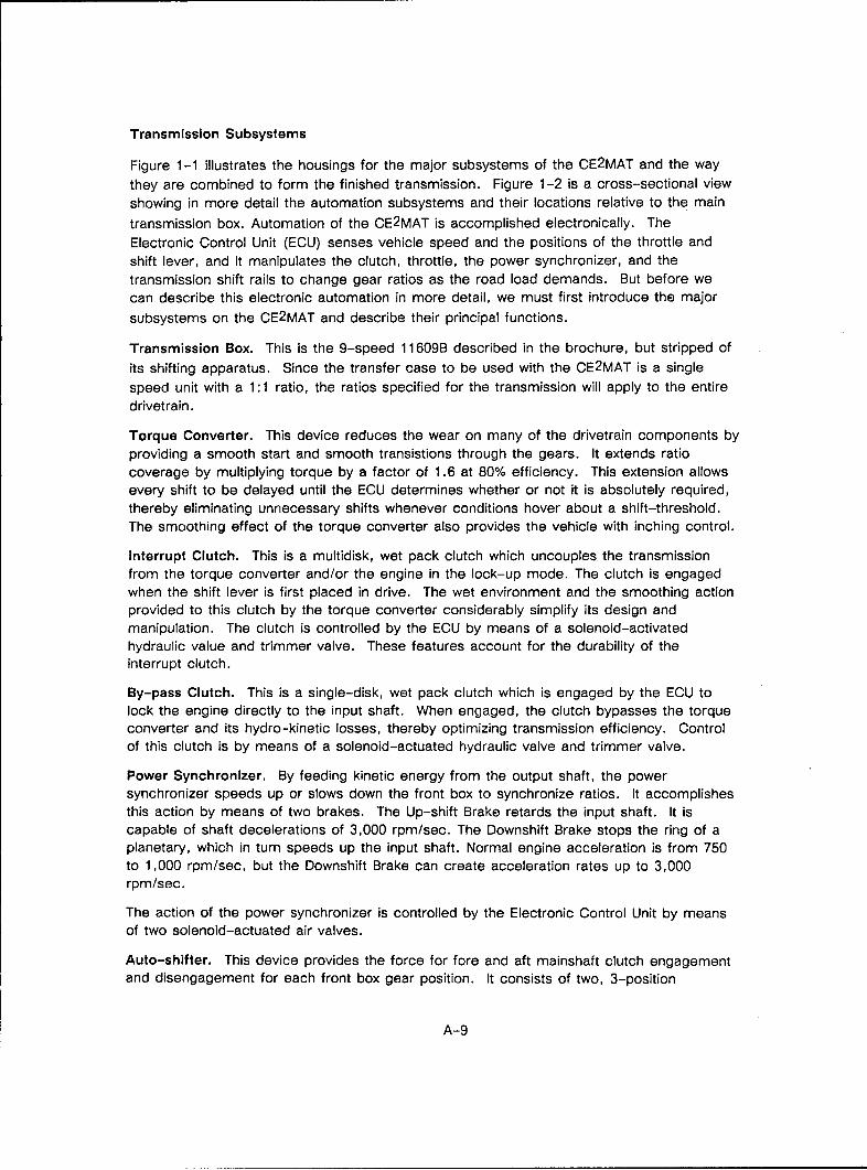
Transmission Subsystems
Figure 1-1 illustrates the housings for the major subsystems of the CE2MAT and the way
they are combined to form the finished transmission. Figure 1-2 is a cross-sectional view
showing in more detail the automation subsystems and their locations relative to the main
transmission box. Automation of the CE2MAT is accomplished electronically. The
Electronic Control Unit (ECU) senses vehicle speed and the positions of the throttle and
shift lever, and it manipulates the clutch, throttle, the power synchronizer, and the
transmission shift rails to change gear ratios as the road load demands. But before wecan describe this electronic automation in more detail, we must first introduce the major
subsystems on the CE2MAT and describe their principal functions.
Transmission Box. This is the 9-speed 11609B described in the brochure, but stripped of
its shifting apparatus. Since the transfer case to be used with the CE2MAT is a single
speed unit with a 1:1 ratio, the ratios specified for the transmission will apply to the entire
drivetrain.
Torque Converter. This device reduces the wear on many of the drivetrain components byproviding a smooth start and smooth transistions through the gears. It extends ratio
coverage by multiplying torque by a factor of 1.6 at 80% efficiency. This extension allows
every shift to be delayed until the ECU determines whether or not it is absolutely required,thereby eliminating unnecessary shifts whenever conditions hover about a shift-threshold.The smoothing effect of the torque converter also provides the vehicle with inching control.
Interrupt Clutch. This is a multidisk, wet pack clutch which uncouples the transmission
from the torque converter and/or the engine in the lock-up mode. The clutch is engagedwhen the shift lever is first placed in drive. The wet environment and the smoothing actionprovided to this clutch by the torque converter considerably simplify its design and
manipulation. The clutch is controlled by the ECU by means of a solenoid-activatedhydraulic value and trimmer valve. These features account for the durability of theinterrupt clutch.
By-pass Clutch. This is a single-disk, wet pack clutch which is engaged by the ECU tolock the engine directly to the input shaft. When engaged, the clutch bypasses the torqueconverter and its hydro-kinetic losses, thereby optimizing transmission efficiency. Controlof this clutch is by means of a solenoid-actuated hydraulic valve and trimmer valve.
Power Synchronizer. By feeding kinetic energy from the output shaft, the powersynchronizer speeds up or slows down the front box to synchronize ratios. It accomplishes
this action by means of two brakes. The Up-shift Brake retards the input shaft. It iscapable of shaft decelerations of 3,000 rpm/sec. The Downshift Brake stops the ring of aplanetary, which in turn speeds up the input shaft. Normal engine acceleration is from 750to 1,000 rpm/sec, but the Downshift Brake can create acceleration rates up to 3,000rpm/sec.
The action of the power synchronizer is controlled by the Electronic Control Unit by means
of two solenoid-actuated air valves.
Auto-shifter. This device provides the force for fore and aft mainshaft clutch engagementand disengagement for each front box gear position. It consists of two, 3-position
A-9

Main transmission box consistingof a 5-speed front box and 2-speed rear box (range shifter).
Torque Converter for smooth,durable starting • Interrupt and by-pass clutches * Wet environment.
, Power Synchronizer allows rapidshift at engine accel. rates up to
S 3000 rpmsec.
__-' _ '.Auto-Shifter to do the actualshifting and an ECU and network
- to control it all.
Figure 1-1. Stages in the development of the CEEMAT.A-10

1�a)
C
1..a)NC0I-
a) 0
0"',
C�d1�*
0I-
L.
a)-
A-il

actuators in an X-Y configuration. The actuators are driven by air supplied by the engine'sair compressor. Air pressure to the actuators is controlled by the ECU by means of foursolenoids.
Electronic Control Unit (ECU). This device consists of a 9 X 13 inch, multilayered printedcircuit board mounted atop the main transmission box. From various sources it receivesinformation as to range, speed and status. With this data it makes calculations anddecisions, and it implements those decisions by means of control solenoids. Thesolenoids, which are electromagnets, in turn actuate pneumatic or hydraulilc valves. Themicroprocessor used in the transmission ECU is Intel's 8051. It is a relatively simple,common microprocessor with a history of high reliability in automotive applications. Theenitre ECU is protected for electromagnetic interference and high altitude EMP by an
aluminum cover and a lot of printed circuit board ground plane.
Oil Pump. An external, gear-type oil pump provides the hydraulic pressure and flow for
clutch actuation and torque converter cooling.
Cooling flow from the torque converter is at least 9 gpm at 1800 rpm engine speed, plusat least 2 gpm is diverted to the main transmission. Approximately 0.8 gpm of the 2 gpm
is delivered to the power-synchronizer; the remainder is for gear and bearing lubrication.An internal oil filter capable of handling 20+ gpm provided clean oil to the hydraulic valve.
The external hose connections to the CE2MAT shown in Figure 1-1 are for torque converter
cooling oil connections.
Air Requirements. The air supply should be dehydrated and screened for contaminants.As with the brakes, the transmission should have priority of air use over other systemssuch as a Central Tire Inflation System.
Figures 1-3 shows the aluminum cover raised and its contents - the auto-shifter and theECU - exposed. The ECU is anchored on standoffs to the underside of the cover; theauto-shifter is mounted on the deckplate. The wire-runs and harnesses around the ECUare a feature of the prototype only. On the production version they will be entirely replacedby another layer of printed circuit board containing wire traces.
All electrical connections to the ECU are made through the single bayonet-type connectorin the forefront of the housing. Air is supplied to the pneumatic valves of the auto-shifter
through a connector on the right side of the cover.
The ECU is located on the transmission itself, rather than in a more protected environmentsuch as the cab. One reason is that it requires fewer and shorter wire runs than would aremote ECU. This in turn reduces cots, installation time, electromagnetic susceptibility.Furthermore, Eaton has control over the quality and integrity of the system's installation.The system would be assembled and completely tested as a unit by Eaton. The heat andvibration atop the transmission box are no longer obstacles to electronic controls. TheECU is certified for operation to 125°C (257°F), and it has survived a battery ofenvironmental tests for design verification.
System Operation
A block diagram of the electronic management system for the transmission is shown in
Figure 1-4. In this illustration we have, so to speak, lifted the aluminum module cover and
A-12
FigureT1-
A-iF

LU
'U
CO 0/0
cm >
A- 4 u

identified its contents and their interconnections. In general, a lightweight line and a hollow
arrow designates one or more electrical conductors carrying something to the ECU, such
as power or information in the form of electrical signals. A heavy line and solid arrow
designates electrical conductors control signals from the ECU - signals which energize
solenoids and thereby perform some sort of action.
Electrical Power. The ECU has redundant power sources and power cables. Normally,
power is supplied by the engine alternator. If the alternator fails, the ECU will automatically
draw power from the vehicle battery.
Shift-Lever Position. The location and function of the shift tower with the new drive train
will remain unchanged. The positions of the shift lever and the corresponding gears
selected for the CE2MAT are as follows:
Shift LeverPosition Gear Ratio
R 13.14:1N
0.73:11.00:11.38:1
D 1.95:12.79:13.82:15.28:1
(Will downshift to 7.47:1)
2 7.47:1
1 12.56:1
When the driver shifts, the lateral motion which he applies to the shift lever is translatedinto the rotational motion of a shaft. The shaft extends down through the floor of the cab,
through the aluminum module cover, and terminates just above the ECU board. Attached
to the end of the shaft is a permanent magnet, which sweeps a semi-circular array of
Hall-effect switches on the board. There is one switch for each position of the shift lever(and two spares). A Hall-effect switch is a solid-state device which closes in the proximity
of a static magnet field. By means of these switches, the ECU is informed of the driver'sselection of shift position. (Like any switch, a Hall-effect switch translates a mechanical
state into an electrical state. Hall-effect switches are used in this particular application
because they do it with extreme reliability. They have no mechanical parts to fatigue and
break, no contacts to foul).
Throttle Position. By means of a radial potentiometer connected to the throttle pedal, the
ECU is continuously informed of the exact position of the throttle.
Engine RPM, Input Speed, Output Speed. Three magnetic speed pickups inform the ECU
of engine RPM and the shaft speeds at the input and output of the main box. From outputshaft speed, the ECU derives vehicle speed.
A-1 5

Clutch Controls. These consists of two solenoid-operated hydraulic valves. Actuation ofone will engage the main (Interrupt) clutch. Actuation of the other will engage the torqueconverter lock-up clutch.
Throttle Override. Actuation of the idle solenoid will cut fuel to the engine and facilitatesmooth up-shifts.
Auto-Shifter Controls. To shift the transmission, the ECU actuates a combination of foursolenoid-operated pneumatic valves. Gear positions are in turn monitored by the ECU bymeans of three switches located on the autoshift.
Range Box Control. One solenoid-operated air valve is used to select the transmissionrange. When the solenoid is energized, low range is selected. Two switches in the RangeBox Shifter give the ECU a positive indication of which range the range box is in.
Power Synchronizer. The power synchronizer mechanism is activated by two solenoidswhich either Increase or decrease the speed of the front gear box input shaft.
Service Brakes & P.T.O. Two switches, one for each function, inform the ECU as to thestatus of these devices - i.e., engaged or disengaged.
WHY A TORQUE CONVERTER:
The CEEMAT:
Eliminates the concern about dry clutch wear in an on/off highway application of an AMTtype transmission. No wear compensation devices are required in the CEEMAT T/C orclutch, nor are maintenance routines requires.
The CEEMAT:
Eliminates elaborate software routines and more complex throttle control devices which arerequired to modulate both the clutch and engine fuel during vehicle starts in the AMTsystem. The AMT system uses a fly-by wire engine fuel control which electronically appliesthe throttle during downshifts. The CEEMAT system simply turns on the clutch when driveis selected and the operator applies the throttle to move the vehicle. The throttle is closedduring shifts in the CEEMAT system and then returned to the driver's demand. At no timeis the throttle ever increased beyone the driver's demand.
The CEEMAT:
Eliminates the driver's need to depress the throttle to engage the clutch to inch the vehicleas in the AMT system. In the CEEMAT system, the torque converter applies a low level oftorque to the driveline when the shift lever is placed in "D". The CEEMAT will allow thedriver to smoothly modulate the torque with the throttle and easily create very high levelso'f thrust such as would be required to negotiate a stepped obstacle or to pull out of a-deep rut. In the AMT system the high torque slip time is very limited and the torque 'level,cannot 'exceed engine fuel torque; therefore, additional ratio must be provided in the geartrain 'to create the same trust as a torque converter enhanced transmission. If the AMTequipped truck moves too quickly, the driver must depress the brake which he probablydoes with the right foot. (The trottle pedal foot.) With the throttle back at zero, the clutchdisengages. To resume motion, the driver must reenter the restart routine 'by depressingthe throttle again.
A-16
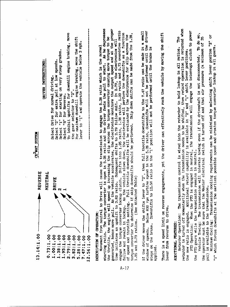
0 -4 $4 ~ .-4 c00 ) ~ 4J4
> >)
4- -4 0 0. .- ' 43-4 -4. a)) a q~ 0-
'00- 'S~0 c 2 , 920 4S 0 '- o43 -4"20
0 0 4-)4 ýA 4-)r4 40 - -4 =L-
4)~ S 0 -4. 2 WV- a) ba -4 20. 4)
EP- 4- 04~ *:34)U .i4i 14~.~4 5>-4 V ) 49~. -1 F=. 0 4 -
4-)C 0J CDO W 0 r-45. C4 U.45..) C
0~ -,0 4)
4-4.. -cb 0 C:co 0 t. .1.-0
-. 0 4 -4 > s , -4 6> 0ý - u ) Io .c+-'f "~0 4-40 c 4-4 "
> 414 > 1 484 n- )C E4 .2 4J
0IW4 Oc3 t 434 t 4-'.-4 Ck c 1 -. 4 =1 0 .as4j .4U.- U)C .4
-4a)42= (DL'%44 0-4 0 )X t-cq4Jaw~. L.~ q W % w p s2@:, b J.
k > ;J0 - - - H)0 44.- kL' 91 0 w .2 -r R U4- Q - ) c
412 94 0 40 0W
4-)4) 4V.3 - O 9 H 4) -4+ 43Q)>-
1. 0 -) :3 c - -"4 4) 0) i 4 - 4 C ~.
0 0c.. 04,- Bt k , oC%42 >bo $%4' 4H 0- O (D43 414. 4
Q)~~~~~-. :- > w w4- 14- 1 4-'
U -40 ((.. -4( - c 4 0
o .4 0 Q)c r C4W(
4-) 4. 4J4 142)9 0C1- q14 4>- -0, 0--4 , - 4. 03
.8 0 02 4.3- . $
.C c:C' a) c4-'C ,4d 4C% C%' C% 0 D* - U) W .
-44 43+ Q. 1- 05- E-4 S C .04-) C .'- W -O '2 ~
C., In Q) 4-3 CQ 4 0)0 0 20)c .2 b 4
U4 -4 064-) 4J ':4-) -ilýJ) M3 4- 3 r_ 30.
A- 17-4 .94
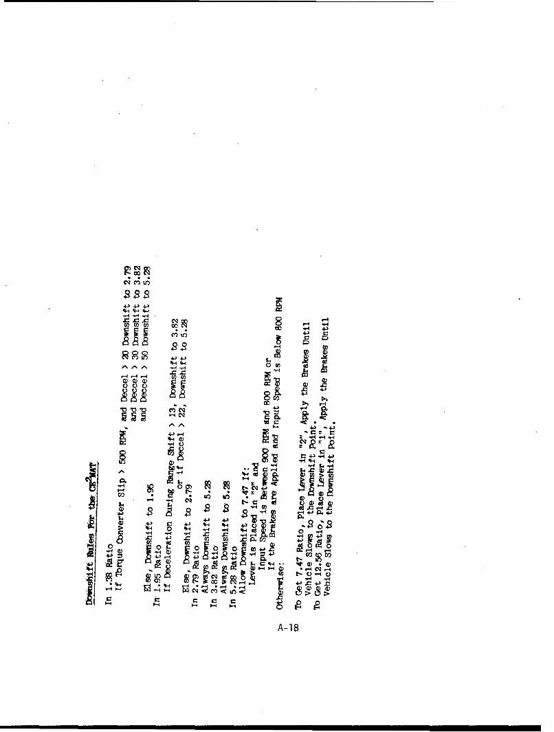
4-) 4-3 4-
4 -4 ~-A -
4-)
Cl)4- +4-4 z,
"59 C'
c
4-4, 0-4
~KCr-* - 4,-)r4 4J
*4, r_ 4, V
0 ~ 4-41
A-lB

APPENDIX B
EATON PROVING GROUNDS
TEST PLAN AND DATA SHEETS
B-1

Attachment - Page 1
REVISED DRAFTApril 10, 1985
TEST PLAN FOR AUTOMATED MECHANICAL TRANSMISSIONRe: Contract DAAE07-82-C-4121
I, Contract Summary:The contractor, as an independent contractor and not as an agent
of the government, shall provide the necessary material, labor,
facilities and technical expertise to adapt a mechanical trans-
mission, Model TSO-11616 Twin Splitter with integral transfercase to meet the United States Army requirements as listed in
Attachment 1 for a five-ton M-939 series truck.
II. Test Plan Objective:The transmission system has been designed, fabricated, and in-
stalled in a M-923, 6x6, cargo truck, a member of the 5-ton M-939
series of tactical trucks.
This test plan will specify the required tests to verify that the
performance goals of the five-ton, M-939 series truck are
achieved.
In addition, the basic transmission function and features will
be documented and reported.
The performance goals are attached to this test plan.
III. Description of Test Item
The Eaton Automated Mechanical Transmission (AMT) is the combin-
ation of a mechanical transmission which was originally designedto be operated manually by the driver, electronic controls andpneumatic actuators in order to create a fully automatic trans-
mission.
B-2

Attachment - Page 2
In order to automate a mechanical transmission which is normally
operated directly by the driver, the engine, clutch, transmissionand electronic logic become a system which controls vehicle
starts and transmission shifting.
Activating mechanisms must be added to replace the driver's handand foot operations, and a controller or electronic logic mustreplace the driver's decision-making process. Such a system isillustrated by the schematic diagram shown in Figure 1.
The additional components required to complete the system are as
follows:
1. Cab lever control for driver input.2. Clutch control mechanism for engaging and releasing
the master clutch.3. Input brake for shift synchronization.
4. Throttle mechanism for fuel control for manipulation
of the engine independent of the driver.5. Main box and auxiliary box shifter mechanisms to engage
the desired gear.6. Air valve manifold with solenoid operators to actuate
the brake, clutch and shifters.
7. Electronic logic control to operate the complete
system.
To provide the all-wheel drive function of the transfer case, an
integral drop box is added to the base TSO-11616 transmission.
IV. Approach to Test Plan
The M-923 6x6 truck with the AMT will be taken to Eaton's ProvingGrounds in Marshall, Michigan. An M-345, pintle type trailer isavailable for test use as may be required.
B-3

Attachment - Page 3
The Eaton Proving Grounds has the following facilities to be used
in performance of this test plan.
1. Weights and vehicle scale for documentation of
GVW or GCW.
2. 1.6 Mile paved oval track.
3. 1050' x 200' skid pad with various coefficient
surfaces.
4. Paved test grades of 20% and 60%.
5. Gravel test grades of 5%, 10%, 15%, 20%, 25%, and
30%.
6. Secondary roads.
7. Cross country test areas which are wooded, rocky
and hilly.
8. Test garage.
9. Fuel available on site.
Prior to the performance of the tests, the truck will have accum-
ulated in excess of 1,000 miles to assure adequate performance of
the system components.
Specific tests will be defined in order to measure the test
truck's performance in comparison to specific performance goals.
The tests shall be repeated a specified number of times in order
to diminish outside influences, (wind velocity, for example) from
assisting in achievement of the goal.
An individual test sheet will be prepared for each test to allow
recording of test parameters, i.e. date, time, temperature, axle
weights, equipment used, etc. as well as defining the pass/fail
criteria. Upon completion of the test, the test sheet will be
signed by the Eaton engineer and the TACOM representative.
B-4

Attachment - Page 4
V. Specific Tests
A. High Speed - Ref: Performance Goal 12.0
Vehicle Load - 50,000 lbs GCW with towed load.Requirement - Operate at a sustained high speed of not less than
50 MPH
Equipment Required - a) M-345 Pintle Trailer, b) Calibrated fifth
wheel for accurate speed measurement.
Method - Record minimum and maximum speeds over each of five laps
(8 miles total) of proving ground's oval track, after transmis-sion is in high gear (16th). Repeat twice.
B. Low Speed - Ref: Performance Goal 13.0Vehicle Load - Not specified
Requirement - Operate at a sustained low speed of not more than
2-1/2 MPH without damage to the vehicle.
Equipment Required - Calibrated fifth wheelMethod - Record ambient temperature and engine water and trans-
mission oil temperatures as test run is started. Drive in lowgear (1st) for 2 miles (48 minutes) and record the engine water
and transmission oil temperatures every 10 minutes until com-pletion of test. Repeat twice.
C. Gradeability on 60% Slope - Ref: Performance Goal 18.0
Vehicle Load - 10,000 lb. payload
Requirement - Negotiate a 60% grade at a minimum speed of 2-1/2
MPH. The grade surface shall be smooth dry concrete.Equipment Required - Instrumentation package to verify engine
speed for vehicle speed calculation.Method - The 60% grade will be negotiated twice. On the second
time, the vehicle shall be stopped and the engine shutdown.
After two minutes, restart the engine and drive vehicle up and
off the grade. Repeat twice.
B-5

Attachment - Page 5
D. High Speed Gradeability - Ref: Performance Goal 13.0
Vehicle Load - 50,000 lb. GCW with towed trailer.
Requirement - Ascend not less than a 2% grade at 30 MPH at 50,000
lb. GCW.
Equipment Required - a) M-345 Pintle trailer, b) Calibrated fifth
wheel.
Method - A stretch of public roadway must be identified with a 2%
minimum sustained grade. The vehicle will approach the grade at
a speed not to exceed 35 MPH and the minimum speed on the gradeshall be recorded. Repeat twice.
E. Cruising Range - Ref: Performance Goal 21.0
Vehicle Load - 10,000 lb. payload plus towed load of 15,000 lbs
including trailer.Requirement - Operate for not less than 300 miles at an average
speed of 30 MPH on hard surfaced road over an average (Michigan)rolling terrain, without refueling.
Equipment Required - Vehicle odometer
Method - Contractor may choose to perform this task during pre-
liminary 1,000 miles of running by advance notice to TACOM. Fueltank will be filled and sealed with wax seal. After completion
of 300 miles with time recorded, seal will be broken and amountof fuel added to tank recorded. This test does not have to be
repeated.
F. Cross Country Operation - Ref: Performance Goal 9.0Vehicle Load - 10,000 lbs. payload plus towed load of 15,000 lbs.
Requirement - The vehicle shall transport rated cross countrypayload and towed load over unimproved roads, trails, openfields, hills and rough cross country terrain.Equipment Required - M-345 trailer with load
Method - Accumulate 3 miles of various cross country conditions
available at Eaton Proving Grounds.
B-6

Attachment - Page 6
G. Panic Braking
Vehicle Load - 10,000 lb. payload
Requirement - The vehicle must be braked without stalling the
engine.
Equipment Required - None
Method - Apply brakes to maximum capacity at vehicle speeds
ranging from 10 MPH to 40 MPH on various coefficient surfaces to
assure that clutch disengages and does not stall engine. Repeat
for eight combinations of speed and surface and record.
H. Shift Performance
Vehicle Loads - 33,000 lbs. GVW to 50,000 lbs. GCW
Requirements - Make oscillograph recordings of various shift con-
ditions.
a) Upshifts on 30% grade in off-road mode
b) Forced downshifts on 30% grade in off-road mode
c) 50,000 lb. GCW upshifts and downshifts in highway shift mode
This will be used to document shift time performance
Equipment Required - a) 10 channel oscillograph, b) M-345 trailer
Method - Establish desired test conditions and record shifts as
required. Breakdown typical shift sequences for time of each
element of shift sequence.
I. Clutch Protection Circuit
Vehicle Load - 35,000 lb. GVW
Requirements - Demonstrate that clutch protection circuit pre-
vents clutch abuse by applying clutch fully if improper gear is
selected for starting. This will either cause engine stall or
wheel slippage depending on road surface and load conditions.
Equipment Required - 10 channel oscillograph
Method - (1) With vehicle loaded to 35,000 lbs., attempt start on
30% grade with transmission in 5th gear (drive position D' on
selector lever). Repeat three times.
(2) By use of towing dynamometer or other loading device, eval-
uate ability to cause wheel slippage with various surface co-
efficients of traction under txcessive starting conditions.
B-7

Attachment - Page 7
J. Acceleration Test
Vehicle Load - Base vehicle, 35,000 lb. GVW; 50,000 lb. GCWRequirements - Determine the time vs. speed to 50 mph under each
load condition on paved level roadway.
.Equipment Required - (a) Calibrated fifth wheel; (b) 10-channel
oscillograph; (c) M-345 trailer
VI. Government Furnished Support Equipment
A M-345 ten-ton, Pintle type trailer has already been delivered
to Eaton Proving Grounds for use in this test plan.
VII. Extent of Contractor Participation
All of the tests shall be performed with contractor engineeringand support personnel. The instrumentation will be provided by
the contractor.
VIII. U.S. Army (TACOM) Participation
A representative of TACOM will witness the tests and sign the
test sheets as tests are completed.
IX InstrumentationThe M-923 test truck has been fitted with a test kit for the AMT
which allows monitoring of the transmission system during oper-ation as well as providing override or limp home capability if a
component malfunction should occur.
B'- 8
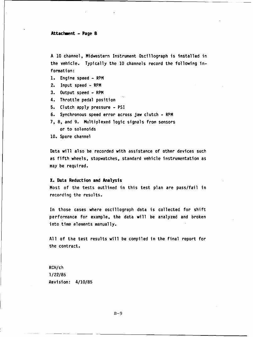
Attachment - Page 8
A 10 channel, Midwestern Instrument Oscillograph is Installed in
the vehicle. Typically the 10 channels record the following in-
formation:
1. Engine speed - RPM
2. Input speed - RPM
3. Output speed - RPM
4. Throttle pedal position
5. Clutch apply pressure - PSI
6. Synchronous speed error across jaw clutch - RPM
7, 8, and 9. Multiplexed logic signals from sensors
or to solenoids
10. Spare channel
Data will also be recorded with assistance of other devices such
as fifth wheels, stopwatches, standard vehicle instrumentation asmay be required.
X. Data Reduction and Analysis
Most of the tests outlined in this test plan are pass/fail in
recording the results.
In those cases where oscillograph data is collected for shift
performance for example, the data will be analyzed and broken
into time elements manually.
All of the test results will be compiled in the final report for
the contract.
RCH/ch
1/22/85
Revision: 4/10/85
B-9

TEST PLAN FOR AUTOMATED MECHANICAL TRANSMISSION
Re: Contract DAAE07-82-C-4121
Data Sheet
A. High Speed - Ref: Performance Goal 12.0
Vehicle Load - 50,000 lbs GCW with towed load.
Requirement - Operate at a sustained high speed of not less than 50
MPH.
Equipment Required - a) M-345 Pintle Trailer, b) Calibrated fifth wheel
for accurate speed measurement.
Method - Record minimum and maximum speeds over each of five laps (8
miles total) of proving ground's oval track, after transmission is in
high gear (16th). Repeat twice.
Test Results:
GCW /t_0 + c2-V,730 + /&/av =C Ic bf ls .(1) (2)
Speed Speed
Lap Min/Max Min/MaxI All, V5ý, -, •a. /s .j-f•/5'. 3 .5/.7/5. 7
3 74 5 /.7 515./. q/.r'. 7
6
7
8
Comuents:
B-10
Et Signature Date
TACOM Witness: ~1k 4 /4 i •

TEST PLAN FOR AUTOMATED MECHANICAL TRANSMISSIONRe: Contract DAAEO7-82-C-4121
Data Sheet
B. Low Speed - Ref: Performance Goal 13.0Vehicle Load - Not specified
Requirement - Operate at a sustained low speed of not more than
2-1/2 MPH without damage to the vehicle.
Equipment Required - Calibrated fifth wheel
Method - Record ambient temperature and engine water and trans-
mission oil temperatures as test run is started. Drive in low
gear (1st) for 2 miles (48 minutes) and record the engine water
and transmission oil temperatures every 10 minutes until completion
of test. Repeat twice.
Test Results:
GVW = 3 4 -0 +/43 Zoe = 4 e, lbs.
1) Ambient Temperature = O_(_ °F
Start 1 2 3 4 Final
Time 62 zc .. O 4 - ;
Engine Coolant OF I _aF /fO /•/o / / D /200(
Trans. Oil OF v or L /
2) Ambient Temperature =F
Start 1 2 3 4 Final
Time At>-•_-_•,_ e .-- r-
Engine Coolant OF , -
Trans. Oil OF / /
Comments:
B-11
ignatureDate
Eaton Witness: ,! / -s
TACOM Witness: /.k4l /¢ 1 ' /

TEST PLAN FOR AUTOMATED MECHANICAL TRANSMISSION
Re: Contract DAAE07-82-C-4121
Data Sheet
9, Low Speed - Ref: Performance Goal 13.0Vehicle Load - Not specified
ReUliro'imht , Operate at a sustained low speed of hot more than
2-1/2 MPH without damage to the vehicle.
Egdlpment Required - Calibrated fifth wheel
Method - Record ambient temperature and engine water and trans-
mission bil temperatures as test run is started. Drive in low
gear (1st) for 2 miles (48 minutes) and record the engine water
ahd transmission oil temperatures every 10 minutes until tompletion
of test. Repeat twice.
Test Results: k,3 5;k
Uw - t, Y.5 + ý '2 Yrf = S 3 lbs.
I) Ambient Temperature = O3 0 F
Start 1 2 43 Final
time J0- v''V e~8 0
Engine Coolant OF / i /7•i c /?SF• /'•F
Trans. Oil 'OF 450 *r-f , 1-10 o
2) 'Ambient Temperature = O_.__F
Start 1 2 3 14 Fi nal
Ti me
tngine ,'Coolant OF
Trans. Oil 'OF
Comments:
B -12
,n .. Signature, 'Date
Eaton Vitness: A___________
*TACOM Witness:, -MA4Ut

TEST PLAN FOR AUTOMATED MECHANICAL TRANSMISSION
Re: Contract DAAE07-82-C-4121
Data Sheet
C. Gradeability on 60K% Slope - Ref: Performance Goal 18.0Vehicle Load - 10,000 lb. payload
Requirement - Negotiate a 60% grade at a minimum speed of 2-1/2 MPH.
The grade surface shall be smooth dry concrete.
Equipment Required - Instrumentation package to verify engine speed
for vehicle speed calculation.
Method - The 60% grade will be negotiated twice. On the second time,
the vehicle shall be stopped and the engine shutdown. After two
minutes, restart the engine and drive vehicle up and off the grade.
Repeat twice.
Test Results:
GVW 77 + Z/•574 = 32 13 S 1 bs.
1) Climb 60% Grade
2) Stop and Restart on 60% grade
3) Repeat 1
4) Repeat 2
Comiments:
B-13
Signature Date
Eaton Witness: 406/6TACOM Witness:_ _ _ _ _ _ _ __ _ _ _ _ _ _ _

TEST PLAN FOR AUTOMATED MECHANICAL TRANSMISSION
Re: Contrct DAAE07-82-C-4121
Data Sheet
D. High Speed Gradeability - Ref: Performance Goal 13.0
Vehicle Load - 50,000 lb. GCW with towed trailer.
Requirement - Ascend not less than 2% grade at 30 MPH at 50,000 lb.
GCW.
Equipment Required - a) M-345 Pintle trailer, b) Calibrated fifth
wheel.
Method - A stretch of public roadway must be identified with a 2%
minimum sustained grade. The vehicle will approach the grade at a
speed not to exceed 35 MPH and the minimum speed on the grade shall be
recorded. Repeat twice.
Test Results:
1) GC 3 ,'-oo X' 4/,re--)lbs.
2) Route Description:
S~/3"
0 ~ /-5' 3 1ý ,5 ¶
.;>i'x (-63ct77-Afs (2)ý()(2)
3) Speed on Grade: Min/Max Min/Max
Comments: /
B-14
Sinature Date
Eaton Witness:
TACOM Witness: ______/__-___

TEST PLAN FOR AUTOMATED MECHANICAL TRANSMISSIONRe: Contract DAAE07-82-C-4121
Data Sheet
E. Cruising Range - Ref: Performance Goal 21.0
Vehicle Load - 10,000 lb. payload plus towed load of 15,000 lbs.
including trailer.
Requirement - Operate for not less than 300 miles at an average speed
of 30 MPH on hard surfaced road over an average (Michigan) rolling
terrain, without refueling.
Equipment Required - Vehicle odometer
Method - Contractor may choose to perform this task during preliminary
1,000 miles of running by advance notice to TACOM. Fuel tank will be
filled and sealed with wax seal. After completion of 300 miles with
time recorded, seal will be broken and amount of fuel added to tank
recorded. This test does not have to be repeated.S5TAF-7T •u[ o)C••Lq7'
Test Results: /0.
Miles completed = miles - : 4'
Travel time = / 3 ,• hours
Average speed = , MPH (calculated)
Fuel consumed = gallons
Fuel consumption = _,_ MPG (calculated)
Comments:7-• 4/•7 7,. 3 A e oa'4? 7.%,•XL
~ C,~ ~ ~ V27 S;
d~~"e do~A/
Z ature I Date
Eaton Witness "*]_________-
TACOM Witness:_ _ _ _ __-_ _
B-15

TEST PLAN FOR AUTOMATED MECHANICAL TRANSMISSION
Re: Contract DAAE07-82-C-4121
Data Sheet
F. Cross Country Operation - Ref: Performance Goal 9.0
Vehicle Load - 10,000 lbs. payload plus towed load of 15,000 lbs.Requirement - The vehicle shall transport rated cross countrypayload and towed load over unimproved roads, trails, openfields, hills and rough cross country terrain.Equipment Required - M-345 trailer with loadMethod - Accumulate 3 miles of various cross country conditionsavailable at Eaton Proving Grounds
test Results:
Course Description:
-C2 C 1
Comments:
B-16
S'nnaatu~re DateEaton Witness:
__ _______
TACOM Witness: __ _ 114-CA Ae ?

TEST PLAN FOR AUTOMATED MECHANICAL TRANSMISSIONRe: Contract DAAE07-82-C-4121
Data Sheet
G. Panic BrakingVehicle Load - 10,000 lb. payload
Requirement - The vehicle must be braked without stalling the
engine.
Equipment Required - None
Method - Apply brakes to maximum capacity at vehicle speeds
ranging from 10 MPH to 40 MPH on various coefficient surfaces to
assure that clutch disengages nd does not stall engine. Repeat
for eight combinations of speed and surface and record.
Test Results
GVW= /__;_ + ZZ?'.5c = ______ lbs.
Test MPH Road Surface Result
2 "( t'); VcL-
3
6 tCLA I .. .
Comments:As •: x• c -r " £:' , l
Signature Date
Eaton Witness:
TACOM Witness:
BEST AVAILABLE COPY /

TEST PLAN FOR AUTOMATED MECHANICAL TRANSMISSION
Re: Contract DAAE07-82-C-4121
Data Sheet
H. Shift Performance
Vehicle Loads - 33,000 lbs. GVW to 50,000 lbs. GCW
Requirements - Make oscillograph recordings of various shift
conditions.
a) Upshifts on 30% grade in off-road mode
b) Forced downshifts on 30% grade in off-road mode
c) 50,000 lb. GCW upshifts and downshifts in highway shift mode
This will be used to document shift time performance
Equipment Required - a) 10 channel oscillograph, b) M-345 trailer
Method - Establish desired test conditions and record shifts as
required. Breakdown typical shift sequences for time of each element
of shift sequence.
Test Results:
GVW/GCW =+ 3= 9, 3?22 lbs.
Test Condition:
Strip Chart Identification No. 3 //:- Z > -co, nts: -7 - elX V,01V1=-
C~#~9~T 4:3 9c
,/4~A% dg ZUA-A 57(4~:-- Aj aj~~ ,G
701 { ignature Dat
Eaton Witness: , i(a(e -• Date
TACOM Witness: Y B1_" ._
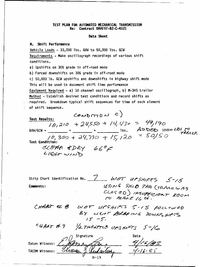
TEST PLAN FOR AUTOMATED MECHANICAL TRANSMISSION
Re: Contract OAAEO7-82-C-4121
Data Sheet
H. Shift Performance
Vehicle Loads - 33,000 lbs. GVW to 50,000 lbs. GCW
Requirements - Make oscillograph recordings of various shift
conditions.
a) Upshifts on 30% grade in off-road mode
b) Forced downshifts on 30% grade in off-road mode
c) 50,000 lb. GCW upshifts and downshifts in highway shift mode
This will be used to document shift time performance
Equipment Required - a) 10 channel oscillograph, b) M-345 trailer
Method - Establish desired test conditions and record shifts as
Srequired. Breakdown typical shift sequences for time of each element
of shift sequence.
Test Results:
GVW/GCW = + = Ibs. ____• -_(_ s>. A t6 '
3o0 + c el73, t /23 /5;5Test Condition:
Strip Chart Identification No. /i/LP•- d5/ g-' 3/6
Comments: VL5/A"11_j .e 10t PAR)
/>s- -r•.
Signature Date
Eaton Witness: ýrý .L -- "_.
TACOM Witness:B-

TEST PLAN FOR AUTOMATED MECHANICAL TRANSMISSIONRe: Contract DAAE07-82-C-4121
Data Sheet
J. Acceleration TestVehicle Load - Base vehicle, 35,000 lb. GVW; 70,000 lb. GCW
Requirements - Determine the time vs. speed to 50 mph under each
load condition on paved level roadway.
Equipment Required - (a) Calibrated fifth wheel; (b) 10-channel
oscillograph; (c) M-345 trailer
Test Results:
GCW/GVW = __,/5_ + 12277 = lbs.
Fifth Wheel Serial Number = /4'.5cr 7V74_7- LR &_ :<.-
Ambient Temperature 63
Test Time Chart (Y/N)
37.33 3
2 a S, 74 ~3V19JO
3
Course Descri pti on:
S7*cr A01- R;'dsc- odr e-ve &~ 441 I &4 < If. rc %-Affo H~
Comments:
Signature Date
Eaton Witness _ _ _ _ _ _
TACOB Witness__B- 20

TEST PLAN FOR AUTOMATED MECHANICAL TRANSMISSIONRe: Contract DAAEO7-82-C-4121
Data Sheet
J. Acceleration Test
Vehicle Load - Base vehicle, 35,000 lb. GVW; 70,000 lb. GCW
Requirements - Determine the time vs. speed to 50 mph under each
load condition on paved level roadway.
Equipment Required - (a) Calibrated fifth wheel; (b) 10-channel
oscillograph; (c) M-345 trailer
Test Results:
W/GVW + 49Z95 + 720 2 = 33.• 9•lbs.
Fifth Wheel Serial Number = /'1 e ' _
Ambient Temperature C- Cr
Test Time Chart (Y/N)
3
Course Description:
Comments:
Signature Date
Eaton Witness ___" _____ -
TACOM Witness Utluj'_B-1
B-21
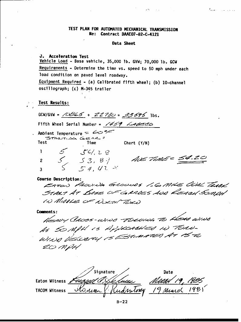
TEST PLAN FOR AUTOMATED MECHANICAL TRANSMISSIONRe: Contract DAAE07-82-C-4121
Data Sheet
J. Acceleration TestVehicle Load - Base vehicle, 35,000 lb. GVW; 70,000 lb. GCWRequirements - Determine the time vs. speed to 50 mph under each
load condition on paved level roadway.
Equipment Required - (a) Calibrated fifth wheel; (b) 10-channeloscillograph; (c) M-345 trailer
Test Results:
GCW/GVW = ____ __ + _____ -- _ ____ lbs.
Fifth Wheel Serial Number = 7s"•9 1 ---__f-de
Ambient Temperature
Test Time Chart (Y/N)
2 43d2, • _ _.....
3 • _•*5//, (!/. -L3
Course Description:
Comments:
2
Si Sgnature Date
Eaton Witness , ~ 9 ~
TACOM Witness 1it(A&-# / ' I -16( I9'• (
B-22

TEST PLAN FOR AUTOMATED MECHANICAL TRANSMISSIONRe: Contract DAAE07-82-C-4121
Data Sheet
J. Acceleration Test
Vehicle Load - Base vehicle, 35,000 lb. GVW; - lb. GCW
Requirements - Determine the time vs. speed to 50 mph under each
load condition on paved level roadway.
Equipment Required - (a) Calibrated fifth wheel; (b) 10-channel
oscillograph; (c) M-345 trailer
Test Results:
Fifth Wheel Serial Number = - - - eV-7' .3y e.•b•'co
Ambient Temperature £-< "
Test Time Chart (Y/N)
2 Al ,,<D '•7•J
3 A J .40.• 3t,]
Course Description:
~~5~'v,%JZ 6:V~2/A' 7 .5 /YZ 4,16- e -1r7L 7~t
Cormrients:
$ Si gnature Date
Eaton Witness __ ___
TAC0B Witness- 3

TEST PLAN FOR AUTOMATED MECHANICAL TRANSMISSION
Re: Contract DAAE07-82-C-4121
Data Sheet
C. Gradeability on 60K% Slope - Ref: Performance Goal 18.0Vehicle Load - 10,000 lb. payload
Requirement - Negotiate a 60% grade at a minimum speed of 2-1/2 MPH.
The grade surface shall be smooth dry concrete.
Equipment Required - Instrumentation package to verify engine speed
for vehicle speed calculation.
Method - The 60% grade will be negotiated twice. On the second time,
the vehicle shall be stopped and the engine shutdown. After two
minutes, restart the engine and drive vehicle up and off the grade.
Repeat twice.
Test Results:
GVW = 12. Y 5 J + -Zo 0 = 0'-43 lbs.
Pass/Fail
1) Climb 60% Grade p, S-
2) Stop and Restart on 60% grade rfý S ý-
3) Repeat 1 (\ 5 -
4) Repeat 2 /on'
Comments:
12, J-T rZ v (Z. C f Y. 0. 1 y )o - t A•L,
Signature Date
Eaton Witness: toX -/(9-
TACOM Witness:
B-24

TEST PLAN FOR AUTOMATED MECHANICAL TRANSMISSIONRe: Contract DAAE07-82-C-4121
Data Sheet
G. Panic Braking
Vehicle Load - 10,000 lb. payload
Requirement - The vehicle must be braked without stalling the
engine.
Equipment Required - None
Method - Apply brakes to maximum capacity at vehicle speeds
ranging from 10 MPH to 40 MPH on various coefficient surfaces to
,assure that clutch disengages nd does not stall engine. Repeat
for eight combinations of speed and surface and record.
Test Results
GVW = I,,5 o + 2__0o 2Z,'-5 lbs.
Test MPH Road Surface Result
2 ,
3 ,-- ) . , WA LL-
4 -1') ,' i A "r ) ,", • -
5
6
7
8
Comments:
Signature Date
Eaton Witness: '\-,,j, (, r,". ,)_,______________
TACOM Witness:
B-25
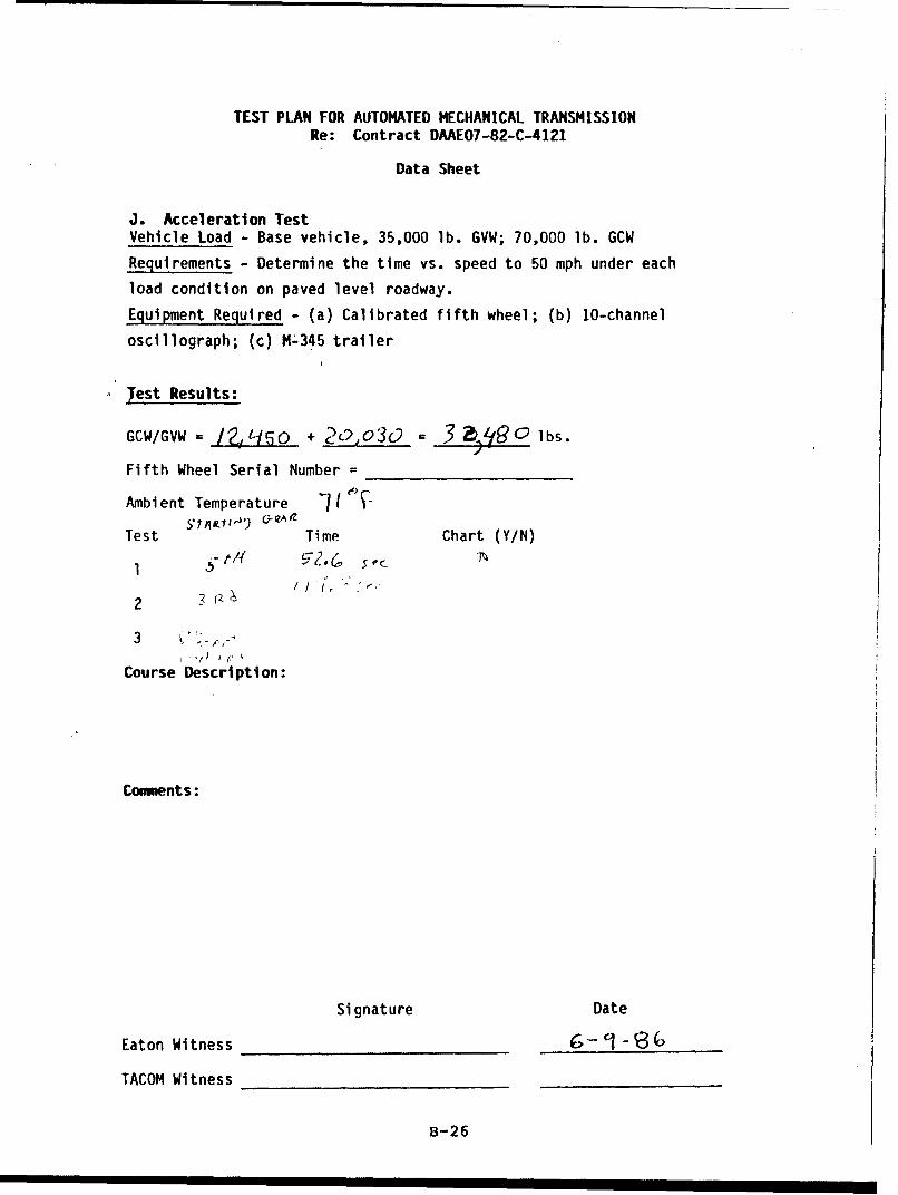
TEST PLAN FOR AUTOMATED MECHANICAL TRANSMISSIONRe: Contract DAAE07-82-C-4121
Data Sheet
J. Acceleration Test
Vehicle Load - Base vehicle, 35,000 lb. GVW; 70,000 lb. GCW
Requirements - Determine the time vs. speed to 50 mph under each
load condition on paved level roadway.
Equipment Required - (a) Calibrated fifth wheel; (b) 10-channel
oscillograph; (c) M-345 trailer
jest Results:
GCW/GVW /?../ L1 0 + 2 , o30 = 3 lbs.Fifth Wheel Serial Number =
Ambient Temperature I I)-
Test Time Chart (Y/N)
2ii ,
3 h
I (" ) j'.' •
Course Description:
Conments:
Signature Date
Eaton Witness _-__ _- (____
TACOM Witness
B-26

TEST PLAN FOR AUTOMATED MECHANICAL TRANSMISSIONRe: Contract DAAE07-82-C-4121
Data Sheet
J. Acceleration Test
Vehicle Load - Base vehicle, 35,000 lb. GVW; 70,000 lb. GCW
Requirements - Determine the time vs. speed to 50 mph under each
load condition on paved level roadway.
Equipment Required - (a) Calibrated fifth wheel; (b) 10-channel
oscillograph; (c) M-345 trailer
Test Results:
GCW/GVW )Ž_?-o + Zo q) = e• .-- i•) lbs.
Fifth Wheel Serial Number =
Ambient Temperature 17 3 '-
Test Time Chart (Y/N)
2 LtS)
3A Q)
Course Description:, ,? ,
Comments:
Signature Date
Eaton Witness ,, V-.
TACOM Witness
B-27

TEST PLAN FOR AUTOMATED MECHANICAL TRANSMISSIONRe: Contract DAAEO7-82-C-4121
Data Sheet
J. Acceleration Test
Vehicle Load - Base vehicle, 35,000 lb. GVW; 70,000 lb. GCW
Requirements - Determine the time vs. speed to 50 mph under each
load condition on paved level roadway.
Equipment Required - (a) Calibrated fifth wheel; (b) 10-channel
oscillograph; (c) M-345 trailer
Test Results:
GCW/GVW = i. ,qso + .2o3o =3Z,'QO . lbs.
Fifth Wheel Serial Number =
Ambient Temperature 1/3 -13
Test Time Chart (Y/N)
1ý ) P)I .. ,
3~~ ,. J. s < ' " C. . ' J , ")
3
Course Description:Io - 191:1 ,u I, "-O---
Comments:
Signature Date
Eaton Witness . yv-,,,,..•,,. {,
TACOM Witness
B-28

TEST PLAN FOR AUTOMATED MECHANICAL TRANSMISSIONRe: Contract DAAE07-82-C-4121
Data Sheet
J. Acceleration TestVehicle Load - Base vehicle, 35,000 lb. GVW; 70,000 lb. GCW
Requirements - Determine the time vs. speed to 50 mph under each
load condition on paved level roadway.
Equipment Required - (a) Calibrated fifth wheel; (b) 10-channel
oscillograph; (c) M-345.trailer
,Test Results:
GCW/GVW VI, 14 /o + ,= lbs.
Fifth Wheel Serial Number =
Ambient Temperature '3 U-
Test , C,,q-r (x Time Chart (Y/N)
2
3 5 e, )L
Course Description:/=•r'a,. f•P',•'•'" (.',?'•')4A • OUc • sT -rcl•A(•-V-
!r',,% e A,.
Comments:
-'- • V.cb•AL~tt.• ",i'QQ,•O'.,,. I €•
Signature Date
Eaton Witness 'Z L _______
TACOM Witness
B-29


APPENDIX C
PROCESSING ANALYSIS OF
COUNTERSHAFT GEAR PN 56453
C-1

F-"T.N Internal Correspondence
Date: August 14, 1997 Project No. 4097-03
To: W. R. Pankratz
Copy: B, Lisowsky
From: D. Vukovich
Subject: PROCESSING ANALYSIS OF COUNTERSHAFT GEAR PN 56453
Conclusions
1, The pitch line case depth does not meet minimum print requirements,2. Root case depth and core hardness are at the minimum required by the
print.3. The sample cracked as a result of low to minimum case depth and core
hardness.4. The gear chemistry is within the range specified for 8620H steel.
Recommendation
Check the residual stress in the roots of gear teeth after assembly(welding) and after testing, prior to removal from the shaft.
Reference
Material hardness specification TES-003.
Sample Selection and Test Procedure
One cracked countershaft gear PN 56453 was submitted for routine hardnessand microstructural evaluation. Case depth and hardness were measured and asample was sent to Chicago Spectrograhic for chemical analysis. Residualstress measurements were not taken because the gear was cut from the shaft,altering the residual stress state.
Chemical Analysis
ELEMENT SAMPLE 8620H SPEC.
C .20 .017/.023Mn .79 .060/.095P .008 .025 Max.S .019 .025 Max.Si .25 .015/.035Ni .47 .035/.075Cr .56 .035/,065Mo .17 .015/.025Cu .14 --
Al .024
C-2Form E30-23 (Rev 12 831

Page TwoW. R. PankratzAugust 14, 1986
Discussion
The countershaft gear (Figure 1A) showed evidence of cracking (Figure 1B) innine tooth roots. A typical root core microstructure contains temperedmartensite and retained austenite. Similar case and core structures werefound at the pitch diameter with the exception that the finer lath marten-site structure is present due to a higher cooling rate during quenching.Evidence of darker etching at the tips of the tooth cross section (notshown) indicates that the tooth tips were tempered (overheated) duringtesting. The overheating explains the observation that the root case is atthe minimum specified depth while the pitchline case is less than specified.
Summary
Table I shows that pitch diameter effective case depth does not meet the.023 inch print specification. All other read 4 ngs just meet minimum printrequirements.
The sample cracked as the result of low to minimum case depth and corehardness.
DTV/iAtt.
C-3

LaJ
LLJ L
I4-
L)
Lc)
LAJC)
LA.
0 - 0 I m
CD L-a)
I UJ
'.0 .0
inw w =-
ICAJ
::. 4-)
L j L.) CV) C
CC C)Q) L
4-'
U - LAJ LA Vl 4
8 1- fl-C,0~0 '0 CC) - O
V4) 0
m coF- Uc ulý-
a-. LO -
c-4

A... COUNTERSHAFT GEAR (56453) SHOWING •I.GEAR TEETH SHOWING LOCATIONLOCATION OF CRACKED TEETH OF CRACKS
C. ROOT CASE MICROSTRUCTURE: PLATE D. ROOT CORE MICROSTRUCTURE: LATH! MARTENSITE AND RETAINED AUSTENITE, MARTENSITE, HRC 26, 500X
SHRC 59, 500X
FIGURE. COUNTERH SHAFT GEAR (56453) SHOWING CRACKED TEETH
ROOT CASE AND CORE MICROSTRUCTURE.
":C-5

APPENDIX D
DROP BOX GEARS - SURFACE RESIDUAL STRESS
D-1
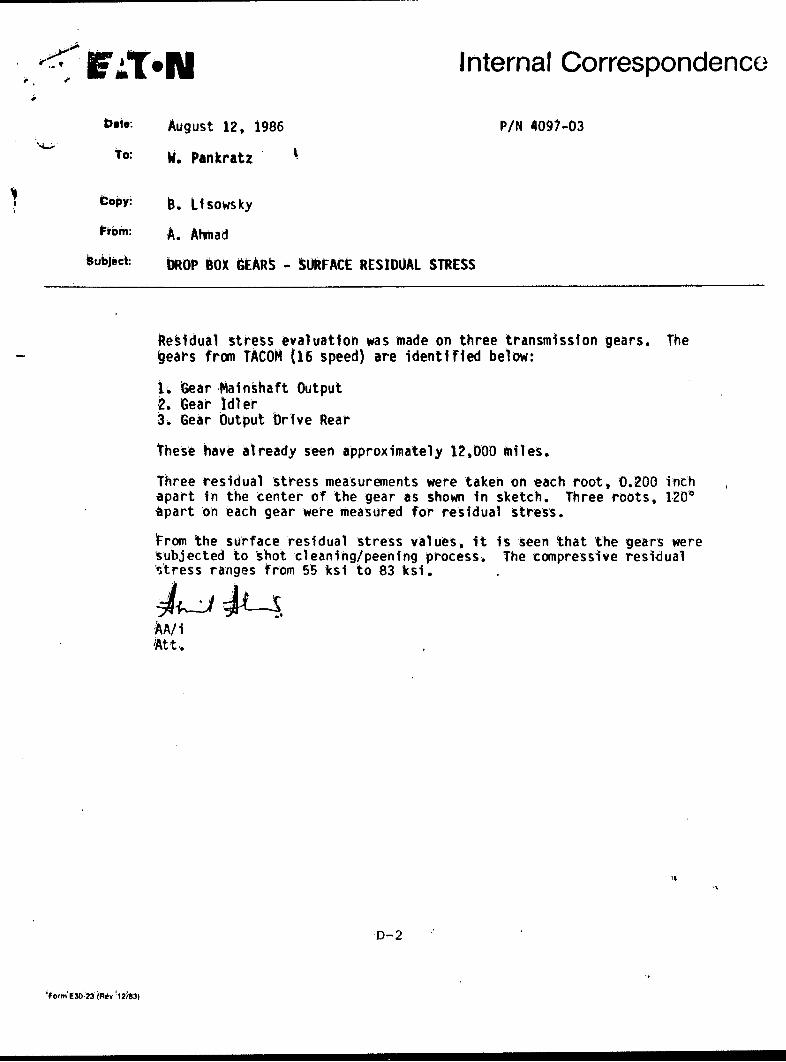
F .I.N Internal Correspondence
nate August 12, 1986 P/N 4097-03
To: W. Pankratz
Copy: B, Llsowsky
From: A. Ahmad
Subject: bROP BOX GEARS - SURFACE RESIDUAL STRESS
Residual stress evaluation was made on three transmission gears. Thegears from TACOM (16 speed) are identified below:
1L Gear Mainshaft Output2. Gear Idler3, Gear Output brive Rear
These have already seen approximately 12,000 miles.
Three residual stress measurements were taken on each root, 0.200 inchapart in the center of the gear as shown in sketch. Three roots, 1200'apart on reach gear were measured for residual Stress.
trom the surface residual stress values, it is seen that the gears weresubjected to shot cleaning/peening process. The compressive residual'stress 'ranges from 55 ksi to 83 ksi.
-AA/ i't t
D-2
'Form E30'-23 iev '1203)

/
II
Orientation and Location ofSurface R.S.
O2ooý
Part # Root # Av. Surface R.S. KSI
56776D 1 1 -612 -613 -55
56833D 1 -622 -723 -57
56839E 1 -832 -753 -83
A.A.7-29-86
D-3


APPENDIX E
DROP BOX GEARS - RESIDUAL STRESS
E-1

E.T*N Internal Correspondence
Date: September 11, 1987 P/N: 3815-03
To: W. Pankratz -- Engineering & Research Center
Copy: B. Lisowsky
From: A. Ahmad -- Engineering & Research Center
Subject: DROP BOX GEARS -- RESIDUAL STRESS
At your request, a gear identified as 56776-D was subjected tosurface and sub-surface residual stress (R.S.) for the verific-ation of processing.
Earlier in August 1986, surface R.S. measurements were performedon 3 gears. At that time sub-surface measurements were not con-ducted, since further testing of these 16-speed gears was ex-pected. A copy of the memo is attached.
The residual stress depth profile obtained on gear 56776-D indi-cates the gear was properly shot peened. The surface, as well assub-surface R.S., particularly at 0.001 inch depth is high com-pressive.
The results obtained on the root are as follows:
Surface - 59 ksiSub-surface (0.0015 inch) -104 ksiSub-surface (0.005 inch) - 44 ksi
Measurements were taken at the bottom of the root at mid-width ofthe gear. Sub-surface readings were obtained after removal of thesurface layer electrolytically (electro-chemical machining). Thedepth of layer removal was determined using a profilometer forroot profile (Fig. 2), as well as replicating the root with amolding compound and measuring the dimensional change usingshadowgraph.
Standard calibration procedure for transmission gear was followed.
M/ch
E-2
form F30-23 (Rev 12/83)
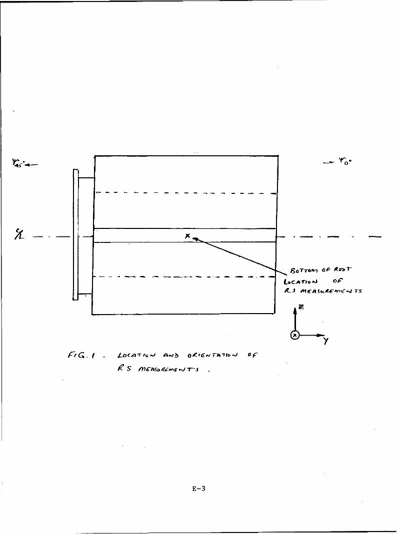
Y'r'
LOCATN.CAIo' oP- 01C P t
E-3

p r i -
"D Jo
a : I
I .
E. -4
- i, -II H
- I- bI,
ii; ' ' -I'-
El -
hJ "
N..- ,,I,
f
S .
I- j
I-,,F ,•' , ,4.
jt!
0II I-

APPENDIX F
INSPECTION REPORT ON AUSCO'S BRAKE
F-1
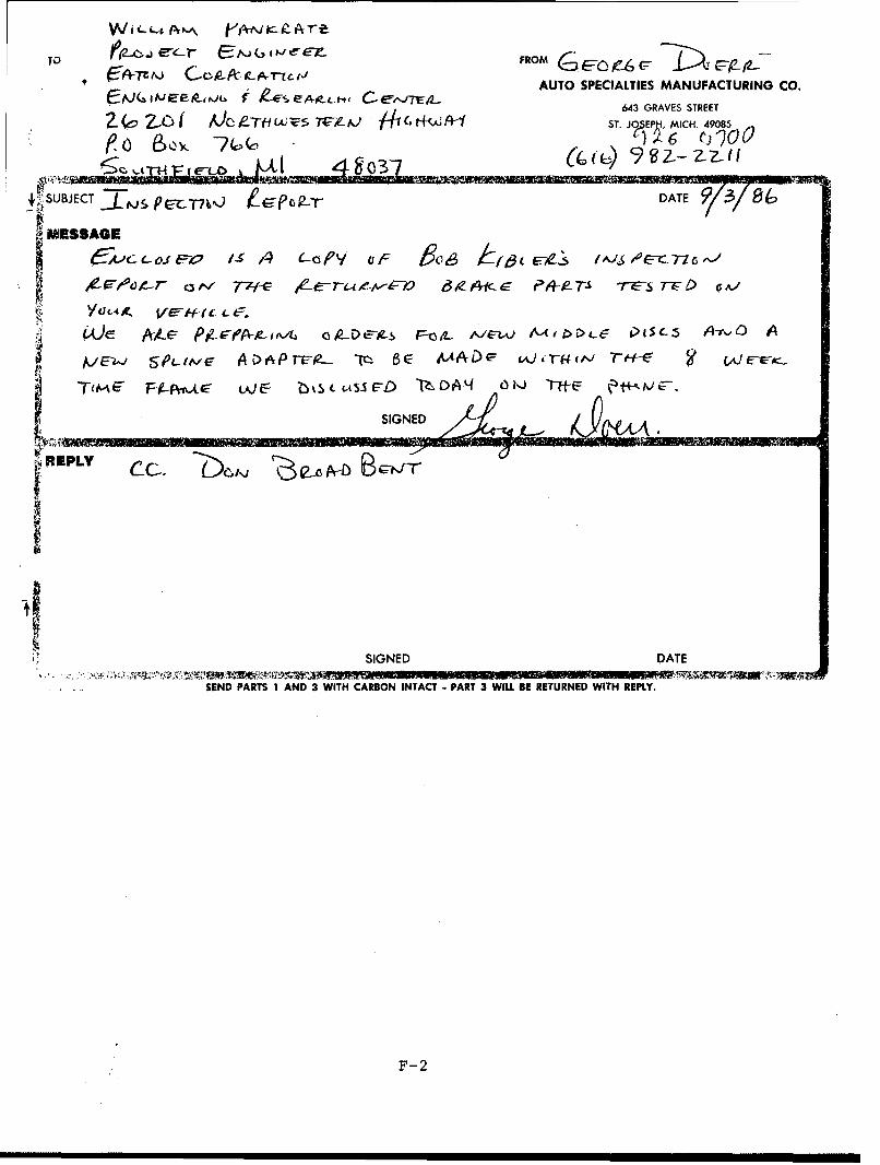
To 621-e-r F , ROM c c-7i pgt.ýýTzo C-p-A-jLA-zcejAUTO SPECIALTIES MANUFACTURING CO.
~IjJ( IJEP~NL~r lESE~~L-4er ,E2 643 GRAVES STREET
Z~c ~ A~cPirf-1LCJ Z5 71r--AJ C1it4kzl ST. J(PEPti, MICH. 49085
ý; SUBJECT GR r-DATE 9K/8SMESSAGE
CAýc c oi& s /4 (-aPY oF &~o6 kjt3tU-s / IO/EA-Cz76'%
AJE~' 5e~'E ADAPrT-IP- -It, 6c MA-De: vt-(4. m1t-"1
SIGNED DATE
SEND PARTS 1 AND 3 WITH CARBON INTACT - PART 3 WILL BE RETURNED WITH REPLY.
F-2

INSPECTION REPORT
OBJECT:
To report "after testing" dimensions of the components of an'
11 x 8 inch multiple disc ball energizing brake, Assembly No.
36525.
PROCEDURE:
Parts were subjected to a "field test" by Eaton. After the
test, all the parts appeared in good condition with exception of
the splines within the middle disc assemblies and on the spline
adapter. The splines were severely worn away in both parts.
Enclosed data sheets show specific dimensions taken from each
part of the assembly. All the dimensions are within drawing
tolerances after testing, except for the splines and a segment of
lining which fell away from the core plate.
CONCLUSIONS:
The splines of the middle disc assemblies will be hardened
to increase the wear capability.
The splines of the spline adapter will be hardened to
increase the wear capability.
The "spalled" lining is not a serious problem. A small
percentage (2%) of production discs may experience some lining
spalling due to a weak interface structure at some localized
areas of the surface of the disc. The amount of lining which
"spalls" or "falls" off the disc will not affect the performance
of the brake.
New middle disc assemblies, and a new spline adapter, will
be made with hardened splines. The remainder of the parts can
continue to be used for vehicle testing.
8/7/basF- 3

I/o42DATA SHEET - ENGINEERING SAMPLE
PROJECT NO. ASSEMBLY NO.__________
T&D JOB NO. 14 53 DATE TESTED:' -/~CUS TOMER: ( P&SO:_______
SERIAL NO. TECHNICIAN____________
SHIPPER NO.____________TEST DATA - COMMENTS: " D tk
Tý I i-P/ A n c
4*11
Fhic~es AqIUim
-P//tI5 9ý
1. ~ Ol~ q351 3 2
In -0
-A14L& no1 l . Sr)AoAZ*4AI VA Ln rŽ - t *5 5b ~ q? B Aq-iess ezcjjv op.)_________
2'Jc- E 5L'M q-5bc,+,oj tz 4 5.ow inU i
~ Atu~4r ~ QILL. ~C~~e- ~f'BLLz~rpF-4.

DATA SHEET - ENGINEERING SAMPLE
PROJECT NO. ASSEMBLY NO.__
T&D JOB NO. /4' ,,-. DATE TESTED:__..__________
CUSTOMER:_ ________P&SO:
SERIAL NO.___________ TECHNI CIAN ?4 PA 6'
SHIPPER NO.TEST DATA - COMMENTS:e
F// J
46dS... /)- Re-•
2.)- R 6 -923),h- e-ca.
0a /, z 0,
~ P'Ja~±A15d C:;ty -gC:14 L, o-~O~7i
lit
F-5

TITLEEA/ERGt.ZLA/G. DISC BIAWE (1.oo x 8.00) PL365., 5______SHEET ' OF I SHEETS
ITEM UNITS IDENTIFICATION NO.SNO. PER DESCRIPTION
ASSY. 1 2 3 4 5 6 7 8 ._
2 1 AA -11113 DISC 95SEjBLY-,9CTrt(T11V&3 4 .. P-41.510 PA/4 . BP-53o0 ST0OUDS Z BP-7001 6/ TA-IU A76 BP-730c1 4 0.5A//v1G7 4 BP- 875"0 Bo9LL8 a BP- 11/IC DISC -/97TQA I&9 B_ P-iII/7l DISC C457/7A/G -4CTr114rlA&
10 p BP- //I /I LS I ,ll- PI_ I /11 5 5p-35/-6- I)A'SER12 2e 24I/94-45,,,13 ?-O-T-/-/X 5?/L514 2 Z ., S .,15 1 3670 4080 t16 / ( 167 e 3)Yus "-17 368,01A&,,477/18 1 3(o b 0.2- V0o0SA/G - COJCV,19 1 368o3 14.ovS 6-.e. s rr/A,/&"9, ,R20 1 -34 8 04- 0,04P7~-" P/A-21 / ( 15a .4.4 C-• S T A/16) & PSPLIA/1D22 4 SLB8O8 DISC ASS9-WgALy -NMIDLC23 4- 3( 7SZ 0/ S C -14IDLC-24 "BPI8o 0 0DISC 6 k-IV/.,V1D'- ZDDL CFI CI/s 6ýD)25 ,5z,,,,-• - 90O•-')26 / 3- 0 14-OId-.'.728293031323334 -.3536373839404142 APR 16 198443
SYM REVISIONS DATE ECO SUPERSEDES PROD. REL.# T #
z -3 1 ' -
CUSTOMER: SA 7-0M CO'RP
EQUIPMENT NAME & MODEL #:
PACKAGING: P/N
a77F
F-61'i i

APPENDIX G
OPERATION AND MAINTENANCE OF THE
EATON TSO-11616
AUTOMATED MECHANICAL TRANSMISSION
G-1

OPERATION AND MAINTENANCE
of the
EATON TSO-11616 AUTOMATED MECHANICAL TRANSMISSION
Prepared Under:Contract 'DAAE07-82-C-4121For: U.S. Army-Tank Automotive 'CommandResearch and Development 'CenterWarren, ,Michigan 48090
Prepared by::Eaton 'CorporationEngineering & Research Center26201 Northwe'stern HighwaySouthfield, 'ichigan 48037'Revised: 'March 1987
T"61N G-'2

Table of Contents
Page
Introduction to the TSO-11616 Transmission . . . . . 1
Shift Lever Operation . . . . . . . . . . . . . .. 2
Electronic Controls . . . . . . . . . . . . . . . . 3
Clutch Operation .................. 3
Transfer Case Operation . . . . . . . . . . . . . . 4
Gear Ratios and Vehicle Speeds . . . . . . . . . . . 5
Lubrication . . . . . . . . . . .. . . . . . . . .. 6
Condensed Specification . . . . . . . . . . . . . . 7
Exterior of Transmission . . . . . . . . . . . . . . 9
Transmission Cross-section . . . . . . . . . . . . . 10
G-3

INTRODUCTION
The Eaton TSO-11616 Automated Mechanical Transmission is a fullyautomatic transmission having 16-speeds forward and two speeds inreverse.
The transmission is connected to the engine by means of a typicaltruck two-plate clutch with ceramic lining material.
To operate the vehicle, the driver just starts the engine, selectsthe proper drive range for the road conditions, releases thebrakes, depresses the throttle pedal and goes.
All of the shift decisions and synchronizing of the transmissionare by the electronic controls, without any involvement beingrequired by the driver.
G-4
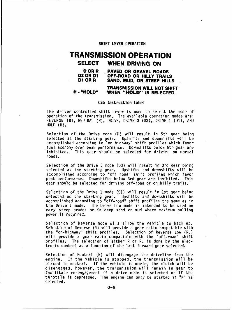
SHIFT LEVER OPERATION
TRANSMISSION OPERATIONSELECT WHEN DRIVING ON
D OR R PAVED OR GRAVEL ROADSD3 OR D1 OFF-ROAD OR HILLY TRAILSD1 OR R SAND, MUD, OR STEEP HILLS
TRANSMISSION WILL NOT SHIFTH - "HOLD" WHEN "HOLD" IS SELECTED.
Cab Instruction Label
The driver controlled shift lever is used to select the mode ofoperation of the transmission. The available operating modes are:REVERSE (R), NEUTRAL (N), DRIVE, DRIVE 3 (03), DRIVE 1 (Dl), ANDHOLD (H).
Selection of the Drive mode (D) will result in 5th gear beingselected as the starting gear. Upshifts and downshifts will beaccomplished according to "on highway" shift profiles which favorfuel economy over peak performance. Downshifts below 5th gear areinhibited. This gear should be selected for driving on normalroads.
Selection of the Drive 3 mode (D3) will result in 3rd gear beingselected as the starting gear. Upshifts and downshifts will beaccomplished according to "off road" shift profiles which favorpeak performance. Downshifts below 3rd gear are inhibited. Thisgear should be selected for driving off-road or on hilly trails.
Selection of the Drive 1 mode (D1) will result in 1st gear beingselected as the starting gear. Upshifts and downshifts will beaccomplished according to "off-road" shift profiles the same as inthe Drive 1 mode. The Drive Low mode is intended to be used onvery steep grades or in deep sand or mud where maximum pullingpower is required.
Selection of Reverse mode will allow the vehicle to back up.Selection of Reverse (R) will provide a gear ratio compatible withthe "on-highway" shift profiles. Selection of Reverse Low (RL)will provide a gear ratio compatible with the "off-road" shiftprofiles. The selection of either R or RL is done by the elec-tronic control as a function of the last forward gear selected.
Selection of Neutral (N) will disengage the driveline from theengine. If the vehicle is stopped, the transmission will beplaced in neutral. If the vehicle is moving the clutch will bedisengaged, however, the transmission will remain in gear tofacilitate re-engagement if a drive mode is selected or if thethrottle is depressed. The engine can only be started if "N" isselected.
G-5
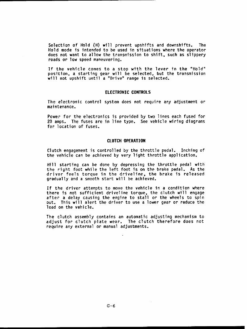
Selection of Hold (H) will prevent upshifts and downshifts. TheHold mode is intended to be used in situations where the operatordoes not want to allow the transmission to shift, such as slipperyroads or low speed maneuvering.
If the vehicle comes to a stop with the lever in the "Hold"position, a starting gear will be selected, but the transmissionwill not upshift until a "Drive" range is selected.
ELECTRONIC CONTROLS
The electronic control system does not require any adjustment ormaintenance.
Power for the electronics is provided by two lines each fused for20 amps. The fuses are in line type. See vehicle wiring diagramsfor location of fuses.
CLUTCH OPERATION
Clutch engagement is controlled by the throttle pedal. Inching ofthe vehicle can be achieved by very light throttle application.
Hill starting can be done by depressing the throttle pedal withthe right foot while the left foot is on the brake pedal. As thedriver feels torque in the driveline, the brake is releasedgradually and a smooth start will be achieved.
If the driver attempts to move the vehicle in a condition wherethere is not sufficient driveline torque, the clutch will engageafter a delay causing the engine to stall or the wheels to spinout. This will alert the driver to use a lower gear or reduce theload on the vehicle.
The clutch assembly contains an automatic adjusting mechanism toadjust for clutch plate wear. The clutch therefore does notrequire any external or manual adjustments.
G-6
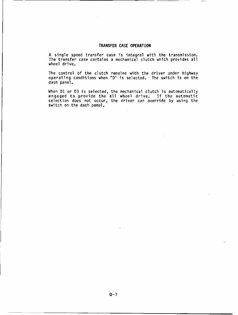
TRANSFER CASE OPERATION
A single speed transfer case is integral with the transmission.The transfer case contains a mechanical clutch which provides allwheel drive.
The control of the clutch remains with the driver under highwayoperating conditions when "D" is selected. The switch is on thedash panel.
When D1 or D3 is selected, the mechanical clutch is automaticallyengaged to provide the all wheel drive. If the automaticselection does not occur, the driver can override by using theswitch on the dash panel.
G-7
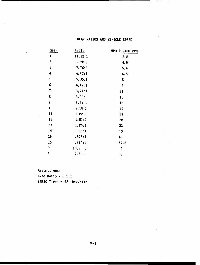
GEAR RATIOS AND VEHICLE SPEED
Gear Ratio MPH @ 2400 RPM1 11.12:1 3.8
2 9.28:1 4.53 7.76:1 5.4
4 6.42:1 6.55 5.36:1 8
6 4.47:1 9
7 3.74:1 11
8 3.09:1 13
9 2.61:1 16
10 2.18:1 1911 1.82:1 23
12 1.51:1 2813 1.26:1 33
14 1.05:1 4015 .875:1 48
16 .724:1 57.6R 10.23:1 4R 7.31:1 6
Assumptions:
Axle Ratio = 8.2:1
14R20 Tires = 421 Rev/Mile
G-8

LuriatonReomenaton
FullerTransmssion
lot j,
. lb
-0
-046

Proper Recommended LubricantsFahrenheit
(Celsius)Grade AmbientL . Type (SAE) Temperatur
Hev Duty to OilMIL-L-2104B, C or D or 50 Above 10*F(-12"C.)
t AP1-F or API.CD 40 Above 10F(-12C.)(Previous ANt designations 30 Wow 10"F(-12"C.)transm ission life accptale "".A-"Mineral Gear Oil with rust 90 Above 10"F(-12°C.)and oxidation inhibitor SOW Below 10*F(-12C.)
Proper lubrication procedures are the key to a APl.GL.1
good all-around maintenance program. If theoil is not doing its job, or if the oil level is The use of mild EP gear oil or multi-pur-ignored, all the maintenance procedures in the pose gear oil is not recommended, but ifworld are not going to keep the transmission these gear oils are used, be sure to adhere torunning or assure long transmission life. the following limitations:
Fuller® Transmissions are designed so that Do not use mild EP gear oil or multi-pur-
the internal parts operate in a bath of oil cir- pose gear oil when operating temperatures
culated by the motion of gears and shafts. are above 230°F (1100C). Many of these gear
Thus, all parts will be amply lubricated if oils, particularly 85W140, break down above230°F and coat seals, bearings and gears with
these procedures are closely followed: deposits that may cause premature failures. Ifthese deposits are observed (especially a
1. Maintain oil level. Inspect regularly. coating on seal areas causing oil leakage),2. Change oil regularly. change to heavy duty engine oil or mineral3. Use the correct grade and type of oil. gear oil to assure maximum component life4. Buy from a reputable dealer. and to maintain your warranty with Eaton.
(Also see "Operating Temperatures".)Additives and friction modifiers are not
recommended for use in Fuller transmissions.
Lubrication Change and Inspection Pmpeopr oil LevI Pe I
HIGHWAY USE
First 3,000 to Change transmission Proper Oil Level5,000 miles (4827 to 8045 Km) oil on new units
Make sure oil is level with filler opening. Be-Every 10,000 miles (16090 Km) Inspect oil level, cause you can reach oil with your finger does
Check for leaks. not mean oil is at proper level. One inch of oillevel is about one gallon of oil.Every 50,000 miles Change transmission i l(80,450 Kin) oil. Draining Oil
Drain transmission while oil is warm. To drainOFF-HIGHWAY USE oil remove the drain plug at bottom of case.
Clean the drain plug before re-installing.First 30 hours Change transmission Refilling
oil on new units. Clean case around filler plug and remove plugEvery 40 hours Inspect oil level. Check for leaks. from side of case. Fill transmission to the
level of the filler opening. If transmission has
Every 500 hours Change transmission oil where two filler openings, fill to level of both open-severe dirt conditions exist. ings.
The exact amount of oil will depend on theEvery 1,000 hours C haget an use). transmission inclination and model. Do not
over fill-this will cause oil to be forced outof the case through front bearing cover.
When adding oil, types and brands of oilOil filter should be changed at each oil change on units should not be intermixed because of possibleequipped with optional external oil filter, 11/,,,1 , , incompatibility.
G-1O
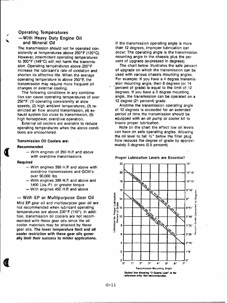
Operating Temperatures-With Heavy Duty Engine Oil
and Mineral Oil If the transmission operating angle is moreThe transmission should not be operated con- than 12 degrees, improper lubrication cansistently at temperatures above 250°F (1206C). occur. The operating angle is the transmissionHowever, intermittent operating temperatures mounting angle in the chassis plus the per-to 300°F (149°C) will not harm the transmis- cent of upgrade (expressed in degrees).sion. Operating temperatures above 250°F The chart below illustrates the safe percentincrease the lubricant's rate of oxidation and of upgrade on which the transmission can beshorten its effective life. When the average used with various chassis mounting angles.operating temperature is above 250°F, the For example: if you have a 4 degree transmis-transmission may require more frequent oil sion mounting angle, then 8 degrees (or 14changes or external cooling. percent of grade) is equal to the limit of 12
The following conditions in any combina- degrees. If you have a 0 degree mountingtion can cause operating temperatures of over angle, the transmission can be operated on a250°F: (1) operating consistently at slow 12 degree (21 percent) grade.speeds, (2) high ambient temperatures, (3) re- Anytime the transmission operating anglestricted air flow around transmission, (4) ex- of 12 degrees is exceeded for an extendedhaust system too close to transmission, (5) period of time the transmission should behigh horsepower, overdrive operation. equipped with an oil pump or cooler kit to
External oil coolers are available to reduce insure proper lubrication.operating temperatures when the above condi- Note on the chart the effect low oil levelstions are encountered. can have on safe operating angles. Allowing
the oil level to fall 1/2" below the filler plugTransmission Oil Coolers are: hole reduces the degree of grade by approxi-
Recommended mately 3 degrees (5.5 percent).
- With engines of 350 H.P. and abovewith overdrive transmissions Proper Lubrication Levels are Essential!
Required 22- 12"
- With engines 399 H.P and above with Ioverdrive transmissions and GCW's 20 I,,.. -O- 1019'
over 90,000 lbs.- With engines 399 H.P and above and 18 10"13'
1400 Lbs.-Ft. or greater torque- With engines 450 H.P. and above 1 9*16,
-With EP or Multipurpose Gear Oil 14a
Mild EP gear oil and multipurpose gear oil are z , ,not recommended when lubricant operating 12 6*51temperatures are above 230°F (1100). In addi- ez r"tion, transmission oil coolers are not recom- * 10 5"48'mended with these gear oils since the oil - - -
cooler materials may be attacked by these 835'
gear oils. The lower temperature limit and oilcooler restriction with these gear oils gener- 6|- , -- ,-- 326' -
ally limit their success to milder applications. 3,26,
4 2"18'
2 18
S0 M0.
i 0 1. 2 3" 4° 5- 6. 7"Transmission Mounting Angle
Dotted line showing "2 Ouarts Low" Is forG reference only- Not recommended.
G-11

Transmission Oil Capacities
Previous Models New Generation
Twin Countershaft Models Pints Liters Pints Liters
T-905 Series 22 10 T.11605 Series 22 10T.955AL Series 25 12 T-11606 26 12T.955ALL Series 28 13 T.8607 Series 36 17T-1056AA 29 14 T-11607 Series 36 17TA.4510 25 12 T.14607 Series 37 17
Roadranger' Twin Countershaft Models
RT-906 26 12 RTO.11607L 28 13RTO.1157DL 27 13 RTO.11607LL 31 15RTO.I157DLL 29 14 RT.8608L 27 13RT-9508 25 12 RT-11608 26 12RTO.958LL 28 13 RT.14608 28 13RTO-1258LL 28 13 RTO-11608LL 29 14RT-9509 Series 25 12 RTO.14608LL 29 14RT.11509 Series 25 12 RT-8609 15 7RT.12509 Series 25 12 RT.11609 Series 27 13RT.610 Series 12 6 RT.12609 Series 27 13RT.910 Series 25 12 RT-14609 Series 27 13RT-1110 Series 25 12 RT.6610 Series 12 6RT.12510 Series 25 12 RT.11610 Series 26 12RT-613 Series 16 8 RT-12610 Series 26 12RT-9513 Series 27 13 RT.14610 Series 26 12RT-12513 27 13 RT-6613 Series 16 8RT.915 Series 28 13 RT-11613 Series 28 13RT.12515 Series 28 13 RT.14613 Series 29 14
RT.15613 Series 29 14
RT.11615 Series 28 13RT.14615 Series 30 14RT.15615 Series 30 14
Auxiliary Transmissions Synchronized Transmissions
AT.1202 11 5 FS-5106 18 92-A-92 12 6 FS-6106 19 9
Nomenclature:Capacity figures listed are based on a 0° installation. Fig-ures are approximate, as exact amount depends upon the R T 0 6 -degree of inclination of engine and transmission. Roadranger-Y IT 'tftRatio Set
Capacity of transmissions equipped with PTO's or oil Twin Countershaft I Forward Speeds
coolers would be greater than capacities listed. Overdrive - Gearing Type (Multi-Mesh)
x 100 = Nominal Torque Capacity
Eaton CorporationTransmission DivisionPO. Box 4013Kalamazoo, Michigan 49003U .TN9/86 - 20M - S.P.C. (616) 342-3344
Form No. 121-R4 1986 Eaton Corporation Printed in U.S.A.
G-12

EATON TSO-11616 AUTOMATED TRANSMISSION
WITH INTEGRAL TRANSFER CASE
SPECIFICATIONS AND DATA
Rating Input TorqueTransmission with T-Case 650 lb-ftTransmission w/o T-Case 1150 lb-ft
Mounting Engine SAE No. i or No. 2 clutch housingVehicle 3-bolt vertical mounting pad each
side
Controls Type Electronic logic with pneumaticvalves for complete automation ofclutch and transmission
Clutch Type 14 in. diameter, 2-plate, pull-typeLining Ceramic
Gearing Type Constant mesh, spur gearsOverall Ratio 15.34:1 with 16 speeds and 20%
stepsTransfer Case Ratio 0.875:1Gear Ratios with T-Case
First 11.12:1Second 9.28:1Third 7.76:1Fourth 6.42:1Fifth 5.36:1Sixth 4.47:1Seventh 3.74:1Eighth 3.09:1Ninth 2.61:1Tenth 2.18:1Eleventh 1.82Twelvth 1.51Thirteenth 1.26:1Fourteenth 1.05:1Fifteenth 0.875:1Sixteenth 0.724:1
Low Reverse 10.23:1High Reverse 7.13:1
Reverse Overall Ratio 14.13:1
G-13

SPECIFICATIONS AND DATA - continued
Oil System Oil Type SAE 30 Engine OilMIL-L-2104D or MIL-L-46152
Oil Cooler OptionalCapacity with T-Case 23 QuartsCapacity w/o T-Case 15 Quarts
Dimensions Length (w/o Parking Brake) 39.08 inches(with T-Case) Width 26.90 inches
Height 26.12 inchesWeight (dry) 1290 lbs.
Dimensions Length (w/o Parking Brake) 42.20 inches(without T-Case) Width 21.10 inches
Height 22.63 inchesWeight (dry) 956.5 lbs.
G-14
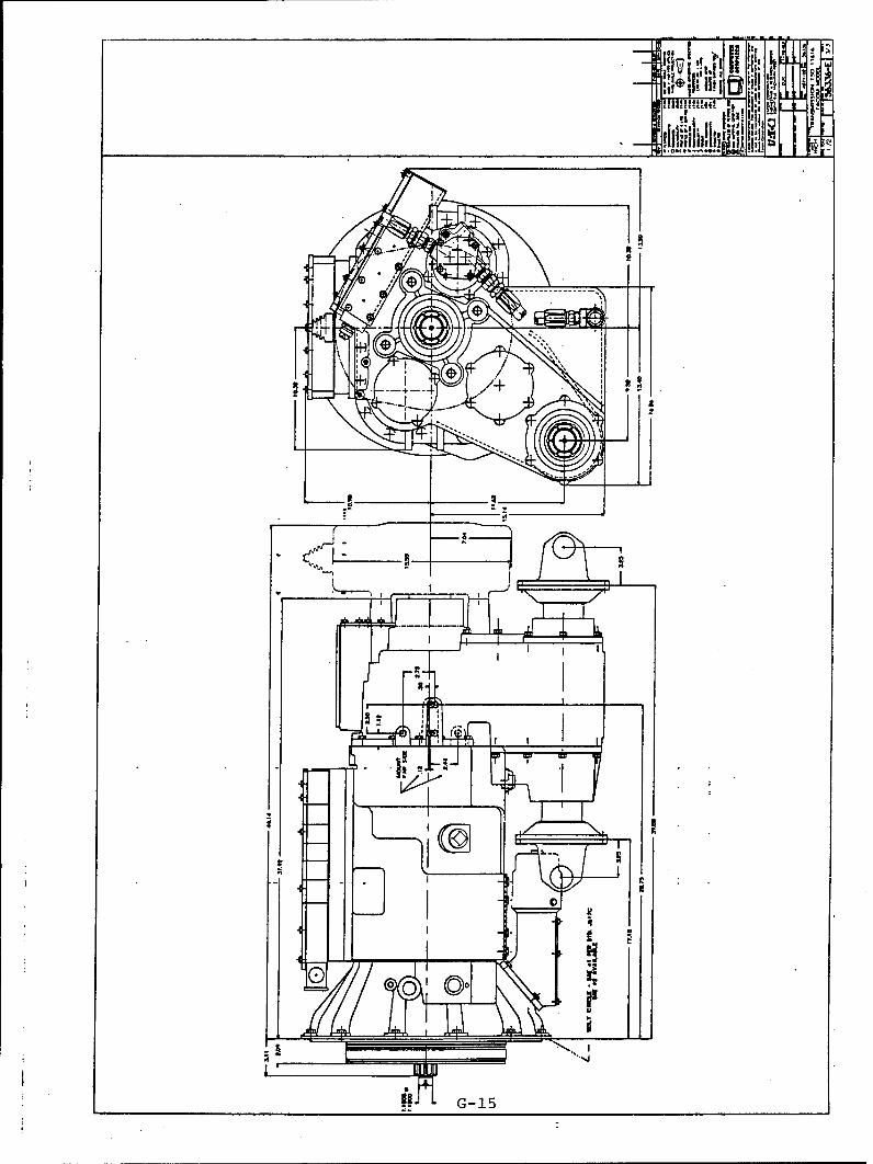
N G-15
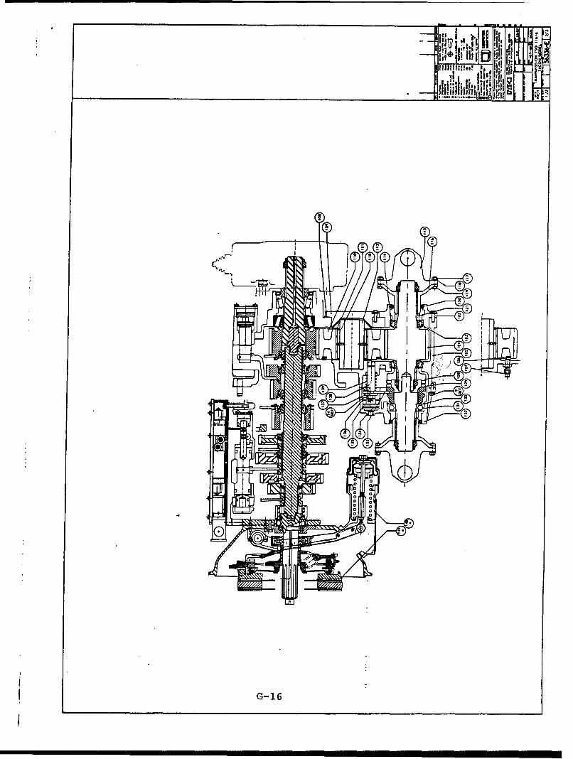
f it a
fill
"Ai 2
G- 16
DISTRIBUTION LIST
Copies:
Commander 5U.S. Army TACOMAttn: AMSTA-RGTWarren, MI 48090
Commander 14U. S. Army TACOMAttn: AMSTA-TSLWarren, MI 48090
CommanderU.S. Army TACOMAttn: AMSTA-NSWarren, MI 48090
Commander 2U.S. Army TACOMAttn: AMSTA-QSWarren, MI 48090
Commander 3U.S. Army TACOMAttn: AMSTA-HWarren, MI 48090
CommanderU.S. Army TACOMAttn: AMSTA-TSEWarren, MI 48090
CommanderU.S. Army TACOMAttn: AMSTA-CVWarren, MI 48090
Distribution-1