Embed Size (px)
Citation preview


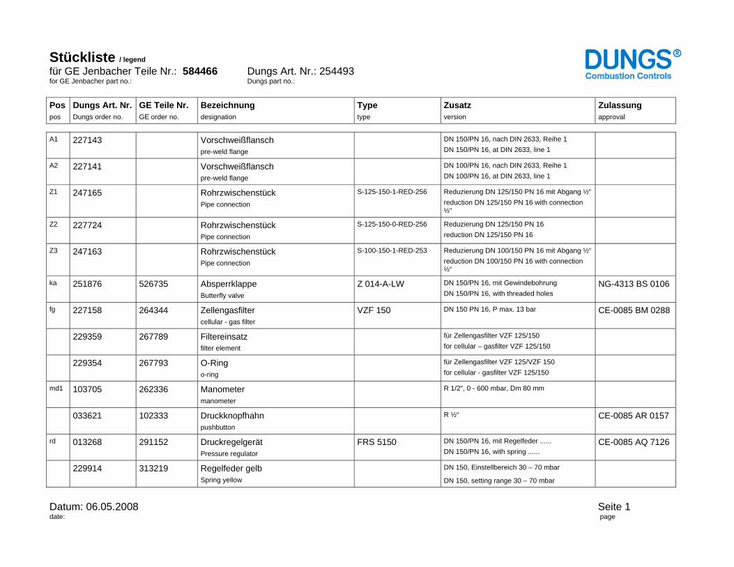
Stückliste / legend für GE Jenbacher Teile Nr.: 584466 Dungs Art. Nr.: 254493 for GE Jenbacher part no.: Dungs part no.: Pos pos
Dungs Art. Nr. Dungs order no.
GE Teile Nr. GE order no.
Bezeichnung designation
Type type
Zusatz version
Zulassung approval
Datum: 06.05.2008 Seite 1 date: page
A1 227143 Vorschweißflansch pre-weld flange
DN 150/PN 16, nach DIN 2633, Reihe 1 DN 150/PN 16, at DIN 2633, line 1
A2 227141 Vorschweißflansch pre-weld flange
DN 100/PN 16, nach DIN 2633, Reihe 1 DN 100/PN 16, at DIN 2633, line 1
Z1 247165 Rohrzwischenstück Pipe connection
S-125-150-1-RED-256 Reduzierung DN 125/150 PN 16 mit Abgang ½“ reduction DN 125/150 PN 16 with connection ½“
Z2 227724 Rohrzwischenstück Pipe connection
S-125-150-0-RED-256 Reduzierung DN 125/150 PN 16 reduction DN 125/150 PN 16
Z3 247163 Rohrzwischenstück Pipe connection
S-100-150-1-RED-253 Reduzierung DN 100/150 PN 16 mit Abgang ½“ reduction DN 100/150 PN 16 with connection ½“
ka 251876 526735 Absperrklappe Butterfly valve
Z 014-A-LW DN 150/PN 16, mit Gewindebohrung DN 150/PN 16, with threaded holes
NG-4313 BS 0106
fg 227158 264344 Zellengasfilter cellular - gas filter
VZF 150 DN 150 PN 16, P max. 13 bar CE-0085 BM 0288
229359 267789 Filtereinsatz filter element
für Zellengasfilter VZF 125/150 for cellular – gasfilter VZF 125/150
229354 267793 O-Ring o-ring
für Zellengasfilter VZF 125/VZF 150 for cellular - gasfilter VZF 125/150
md1 103705 262336 Manometer manometer
R 1/2", 0 - 600 mbar, Dm 80 mm
033621 102333 Druckknopfhahn pushbutton
R ½“
CE-0085 AR 0157
rd 013268 291152 Druckregelgerät Pressure regulator
FRS 5150 DN 150/PN 16, mit Regelfeder ...... DN 150/PN 16, with spring ......
CE-0085 AQ 7126
229914 313219 Regelfeder gelb Spring yellow
DN 150, Einstellbereich 30 – 70 mbar
DN 150, setting range 30 – 70 mbar
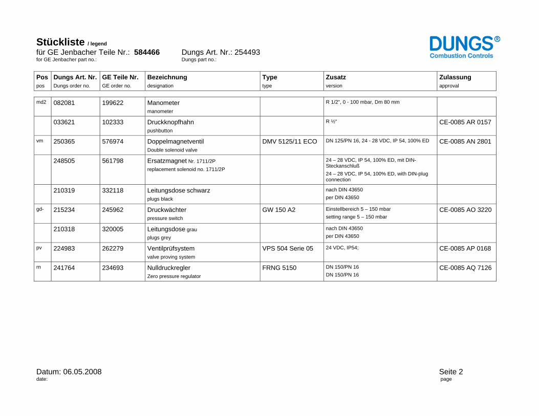
Stückliste / legend für GE Jenbacher Teile Nr.: 584466 Dungs Art. Nr.: 254493 for GE Jenbacher part no.: Dungs part no.: Pos pos
Dungs Art. Nr. Dungs order no.
GE Teile Nr. GE order no.
Bezeichnung designation
Type type
Zusatz version
Zulassung approval
Datum: 06.05.2008 Seite 2 date: page
md2 082081 199622 Manometer manometer
R 1/2", 0 - 100 mbar, Dm 80 mm
033621 102333 Druckknopfhahn pushbutton
R ½“
CE-0085 AR 0157
vm 250365 576974 Doppelmagnetventil Double solenoid valve
DMV 5125/11 ECO DN 125/PN 16, 24 - 28 VDC, IP 54, 100% ED CE-0085 AN 2801
248505 561798 Ersatzmagnet Nr. 1711/2P replacement solenoid no. 1711/2P
24 – 28 VDC, IP 54, 100% ED, mit DIN-Steckanschluß 24 – 28 VDC, IP 54, 100% ED, with DIN-plug connection
210319 332118 Leitungsdose schwarz plugs black
nach DIN 43650 per DIN 43650
gd- 215234 245962 Druckwächter pressure switch
GW 150 A2 Einstellbereich 5 – 150 mbar setting range 5 – 150 mbar
CE-0085 AO 3220
210318 320005 Leitungsdose grau plugs grey
nach DIN 43650 per DIN 43650
pv 224983 262279 Ventilprüfsystem valve proving system
VPS 504 Serie 05 24 VDC, IP54;
CE-0085 AP 0168
rn 241764 234693 Nulldruckregler Zero pressure regulator
FRNG 5150 DN 150/PN 16 DN 150/PN 16
CE-0085 AQ 7126


Issued: TEE/Hirzinger Checked: Elektronik Date: 2008-10
1510-0064_EN.doc Index: k Page - No.: 1 / 11
Technical Instruction No.: 1510-0064Gas quantity controller (TecJet 110 and 50 plus)
EN
Jenbacher Documentation
1. Introduction:_______________________________________________________ 2
2. Description of the system: ___________________________________________ 2 2.1 Mechanical assembly of the device: 2 2.2 Gas pressure/gas quality limiting conditions: 4 2.3 Electrical connection: 4 2.3.1 Device connector: 4 2.3.2 Relevant connecting cable: 4 2.3.3 Power supply: 5 2.3.4 CAN – coupling: 5 2.3.5 Coding / release of the device: 5 3. Commissioning:____________________________________________________ 5 3.1 Parameter setting: 5 3.1.1 Indicative values for the GAS PROPORTIONING VALVE/TECJET RECIPE: 5 3.1.2 LEANOX recipe: 8 3.1.3 ENGINE DATA recipe: 8 3.2 Dia.ne visualisation screens: 8 3.2.1 LEANOX: 8 3.2.2 DETAILS - GAS: 8 3.2.3 SYSTEM: 8 4. Troubleshooting: ___________________________________________________ 9 4.1 Failure messages: 9 4.1.1 Tripping: 9 4.1.2 Warning: 10 4.2 Troubleshooting: 10 4.2.1 Power supply problems (voltage supply, CAN bus): 10 4.3 Mechanical problems (gas quality and pressure): 11 4.4 Electronic problems (internal errors): 11
Issued: TEE/Hirzinger Checked: Elektronik Date: 2008-10
1510-0064_EN.doc Index: k Page - No.: 2 / 11
Technical Instruction No.: 1510-0064Gas quantity controller (TecJet 110 and 50 plus)
EN
Jenbacher Documentation
1. Introduction:
Using the TecJet gas proportioning valve it is possible to specify a desired gas volume. This makes it possible to dispense with the gas mixer used until now, and allows you to actively intervene to make mixtures more lean or rich and to directly preset the fuel mixture lambda value. The fuel mixture lambda value is the ratio between the actual combustion air volume and the stoichiometrically required air volume. That is why stoichiometric combustion equals lambda = 1, resulting in improved behaviour while starting and during isolated operation. A zero controller pressure is no longer required. This type of gas proportioning valve can be used in combination with both natural gas and special gasses.
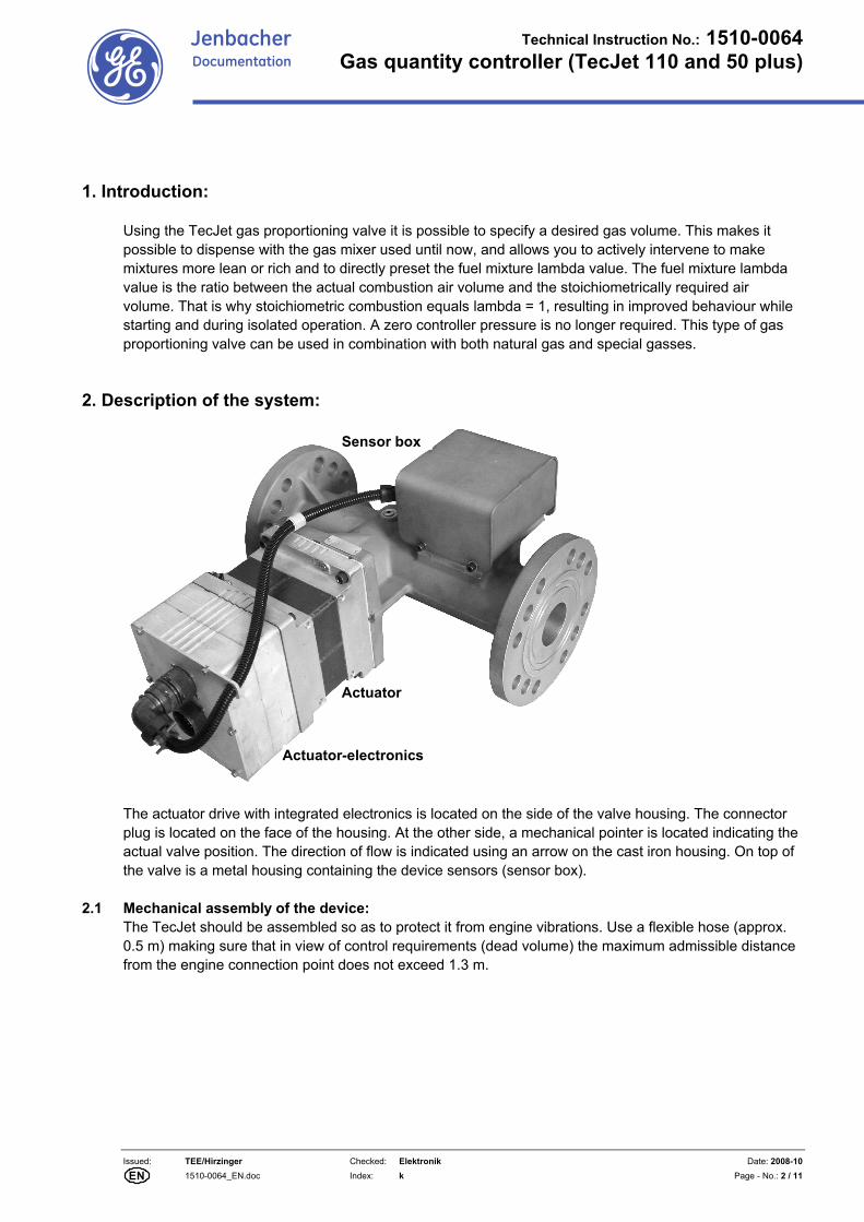
2. Description of the system:
The actuator drive with integrated electronics is located on the side of the valve housing. The connector plug is located on the face of the housing. At the other side, a mechanical pointer is located indicating the actual valve position. The direction of flow is indicated using an arrow on the cast iron housing. On top of the valve is a metal housing containing the device sensors (sensor box).
2.1 Mechanical assembly of the device: The TecJet should be assembled so as to protect it from engine vibrations. Use a flexible hose (approx. 0.5 m) making sure that in view of control requirements (dead volume) the maximum admissible distance from the engine connection point does not exceed 1.3 m.
Sensor box
Actuator
Actuator-electronics

Issued: TEE/Hirzinger Checked: Elektronik Date: 2008-10
1510-0064_EN.doc Index: k Page - No.: 3 / 11
Technical Instruction No.: 1510-0064Gas quantity controller (TecJet 110 and 50 plus)
EN
Jenbacher Documentation
As a guideline, a distance of up to 2 m (at least 6x the nominal diameter) between TecJet and the solenoid valves must be maintained to provide a damping system. This should already be taken into account by the manufacturer in the design of the gas pressure control system. The manufacturer advises to maintain an intake-sided damping distance of 6x the nominal device diameter and an output-sided damping distance of 2x the nominal device diameter and to assemble the device according to ANSI/ISA-S75.02 to prevent sensitivity losses. By observing the above distances, these requirements are fulfilled. The device is mounted horizontally with the sensor box on top. The direction of flow is indicated by means of an arrow on the cast-iron housing. See the following illustration for the position of the individual gas pressure control system components.
1 Ball valve 5 TecJet gas proportioning valve 2 Micro filter 6 Flexible hose 3 Pre-pressure controller 7 Engine connection point 4 Solenoid valves with leak testing Whenever several fuel gasses need to be mixed, this arrangement is implemented for each individual fuel gas. Once they have passed the gas proportioning valves the gasses are combined and fed to the gas mixer housing or a shared piece of tubing leading to the turbocompressor/compressor intake.
M
PI
SOV SOV
SOV PSPDS
DK1
3 3
PI
PCV
1
max.1,3 m
2 3 4 5 6 7
max.5 m
To e
ngin
e
max. 2 m min.6xDN
Issued: TEE/Hirzinger Checked: Elektronik Date: 2008-10
1510-0064_EN.doc Index: k Page - No.: 4 / 11
Technical Instruction No.: 1510-0064Gas quantity controller (TecJet 110 and 50 plus)
EN
Jenbacher Documentation
2.2 Gas pressure/gas quality limiting conditions: The differential pressure across the device must be in the 10 – 500 mbar range. The intake-sided pressure must be in the 0.4barabs and 1.6 barabs range. The required gas prepressure at the customer interface follows from the required gas volume, the calorific value, the engine efficiency and pressure losses along the gas pressure control system. When determining the required gas prepressure at the customer interface, the relevant guidelines need to be taken into account (the Jenbacher Anlagenkonstruktion and Projektierung departments can help you). The zero pressure controller is no longer required. The prepressure controller is a standard feature as in practice there is no guarantee that TI 1000-0300/-0301 or -0302 will actually be complied with. Make sure that a relative gas-moisture content percentage of 80 % is not exceeded (in accordance with TI 1000-0300/-0301 or -0302) and that measures are taken to prevent condensate from forming (in accordance with TI 1400-0091).
2.3 Electrical connection:
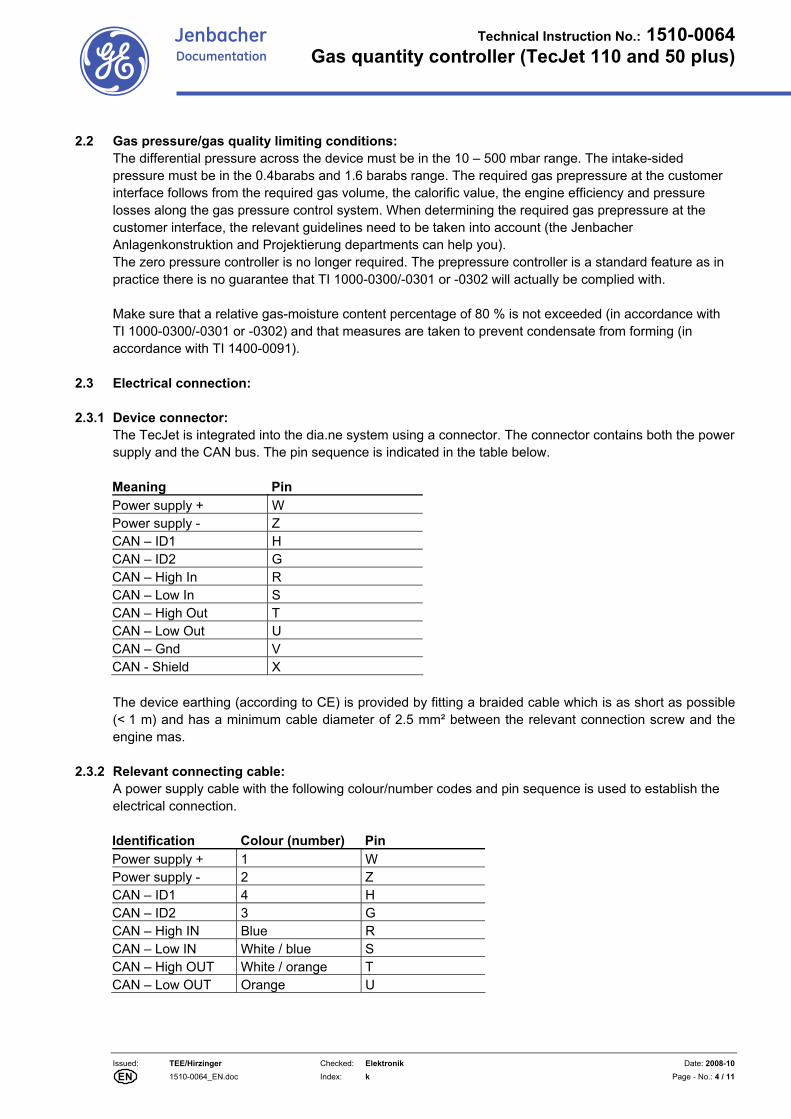
2.3.1 Device connector: The TecJet is integrated into the dia.ne system using a connector. The connector contains both the power supply and the CAN bus. The pin sequence is indicated in the table below. Meaning Pin Power supply + W Power supply - Z CAN – ID1 H CAN – ID2 G CAN – High In R CAN – Low In S CAN – High Out T CAN – Low Out U CAN – Gnd V CAN - Shield X The device earthing (according to CE) is provided by fitting a braided cable which is as short as possible (< 1 m) and has a minimum cable diameter of 2.5 mm² between the relevant connection screw and the engine mas.
2.3.2 Relevant connecting cable: A power supply cable with the following colour/number codes and pin sequence is used to establish the electrical connection. Identification Colour (number) Pin Power supply + 1 W Power supply - 2 Z CAN – ID1 4 H CAN – ID2 3 G CAN – High IN Blue R CAN – Low IN White / blue S CAN – High OUT White / orange T CAN – Low OUT Orange U
Issued: TEE/Hirzinger Checked: Elektronik Date: 2008-10
1510-0064_EN.doc Index: k Page - No.: 5 / 11
Technical Instruction No.: 1510-0064Gas quantity controller (TecJet 110 and 50 plus)
EN
Jenbacher Documentation
2.3.3 Power supply:
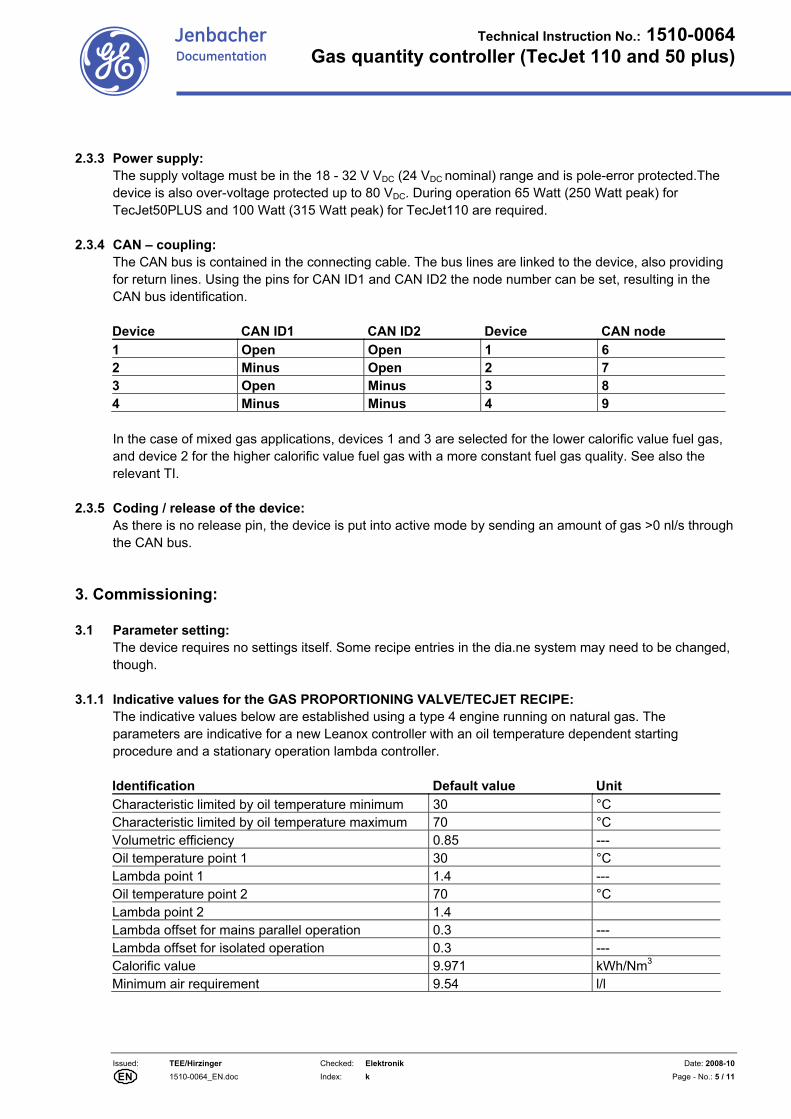
The supply voltage must be in the 18 - 32 V VDC (24 VDC nominal) range and is pole-error protected.The device is also over-voltage protected up to 80 VDC. During operation 65 Watt (250 Watt peak) for TecJet50PLUS and 100 Watt (315 Watt peak) for TecJet110 are required.
2.3.4 CAN – coupling: The CAN bus is contained in the connecting cable. The bus lines are linked to the device, also providing for return lines. Using the pins for CAN ID1 and CAN ID2 the node number can be set, resulting in the CAN bus identification.
Device CAN ID1 CAN ID2 Device CAN node 1 Open Open 1 6 2 Minus Open 2 7 3 Open Minus 3 8 4 Minus Minus 4 9
In the case of mixed gas applications, devices 1 and 3 are selected for the lower calorific value fuel gas, and device 2 for the higher calorific value fuel gas with a more constant fuel gas quality. See also the relevant TI.
2.3.5 Coding / release of the device: As there is no release pin, the device is put into active mode by sending an amount of gas >0 nl/s through the CAN bus.
3. Commissioning:
3.1 Parameter setting: The device requires no settings itself. Some recipe entries in the dia.ne system may need to be changed, though.
3.1.1 Indicative values for the GAS PROPORTIONING VALVE/TECJET RECIPE:
The indicative values below are established using a type 4 engine running on natural gas. The parameters are indicative for a new Leanox controller with an oil temperature dependent starting procedure and a stationary operation lambda controller. Identification Default value Unit Characteristic limited by oil temperature minimum 30 °C Characteristic limited by oil temperature maximum 70 °C Volumetric efficiency 0.85 --- Oil temperature point 1 30 °C Lambda point 1 1.4 --- Oil temperature point 2 70 °C Lambda point 2 1.4 Lambda offset for mains parallel operation 0.3 --- Lambda offset for isolated operation 0.3 --- Calorific value 9.971 kWh/Nm3 Minimum air requirement 9.54 l/l
Issued: TEE/Hirzinger Checked: Elektronik Date: 2008-10
1510-0064_EN.doc Index: k Page - No.: 6 / 11
Technical Instruction No.: 1510-0064Gas quantity controller (TecJet 110 and 50 plus)
EN
Jenbacher Documentation
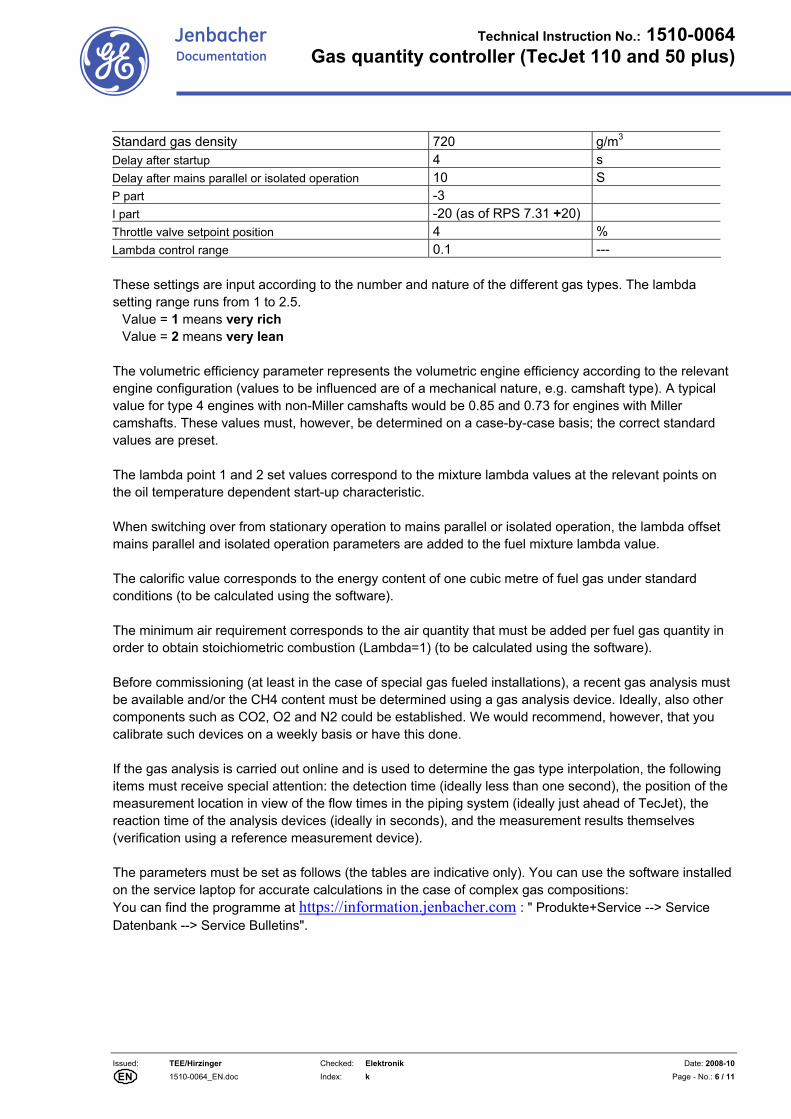
Standard gas density 720 g/m3 Delay after startup 4 s Delay after mains parallel or isolated operation 10 S P part -3 I part -20 (as of RPS 7.31 +20) Throttle valve setpoint position 4 % Lambda control range 0.1 --- These settings are input according to the number and nature of the different gas types. The lambda setting range runs from 1 to 2.5.
Value = 1 means very rich Value = 2 means very lean
The volumetric efficiency parameter represents the volumetric engine efficiency according to the relevant engine configuration (values to be influenced are of a mechanical nature, e.g. camshaft type). A typical value for type 4 engines with non-Miller camshafts would be 0.85 and 0.73 for engines with Miller camshafts. These values must, however, be determined on a case-by-case basis; the correct standard values are preset. The lambda point 1 and 2 set values correspond to the mixture lambda values at the relevant points on the oil temperature dependent start-up characteristic. When switching over from stationary operation to mains parallel or isolated operation, the lambda offset mains parallel and isolated operation parameters are added to the fuel mixture lambda value. The calorific value corresponds to the energy content of one cubic metre of fuel gas under standard conditions (to be calculated using the software). The minimum air requirement corresponds to the air quantity that must be added per fuel gas quantity in order to obtain stoichiometric combustion (Lambda=1) (to be calculated using the software). Before commissioning (at least in the case of special gas fueled installations), a recent gas analysis must be available and/or the CH4 content must be determined using a gas analysis device. Ideally, also other components such as CO2, O2 and N2 could be established. We would recommend, however, that you calibrate such devices on a weekly basis or have this done. If the gas analysis is carried out online and is used to determine the gas type interpolation, the following items must receive special attention: the detection time (ideally less than one second), the position of the measurement location in view of the flow times in the piping system (ideally just ahead of TecJet), the reaction time of the analysis devices (ideally in seconds), and the measurement results themselves (verification using a reference measurement device). The parameters must be set as follows (the tables are indicative only). You can use the software installed on the service laptop for accurate calculations in the case of complex gas compositions: You can find the programme at https://information.jenbacher.com : " Produkte+Service --> Service Datenbank --> Service Bulletins".
Issued: TEE/Hirzinger Checked: Elektronik Date: 2008-10
1510-0064_EN.doc Index: k Page - No.: 7 / 11
Technical Instruction No.: 1510-0064Gas quantity controller (TecJet 110 and 50 plus)
EN
Jenbacher Documentation
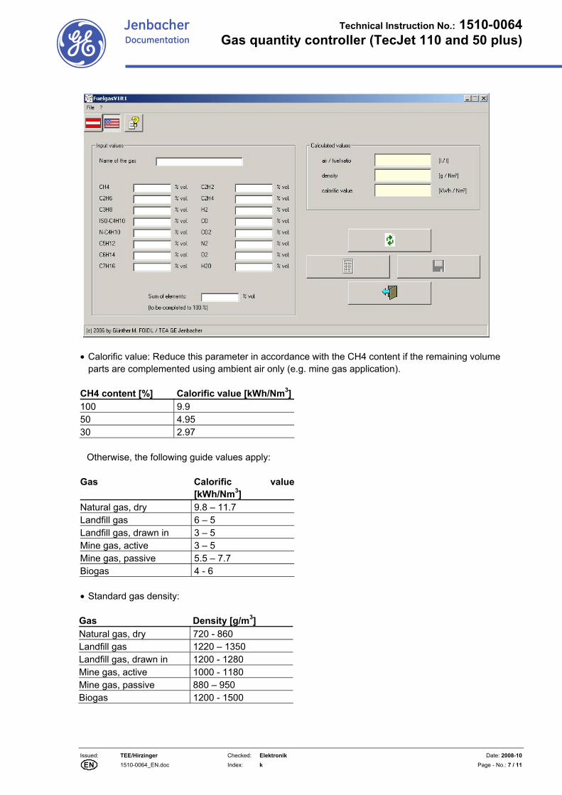
• Calorific value: Reduce this parameter in accordance with the CH4 content if the remaining volume
parts are complemented using ambient air only (e.g. mine gas application). CH4 content [%] Calorific value [kWh/Nm3]100 9.9 50 4.95 30 2.97
Otherwise, the following guide values apply:
Gas Calorific value[kWh/Nm3]
Natural gas, dry 9.8 – 11.7 Landfill gas 6 – 5 Landfill gas, drawn in 3 – 5 Mine gas, active 3 – 5 Mine gas, passive 5.5 – 7.7 Biogas 4 - 6
• Standard gas density: Gas Density [g/m3] Natural gas, dry 720 - 860 Landfill gas 1220 – 1350 Landfill gas, drawn in 1200 - 1280 Mine gas, active 1000 - 1180 Mine gas, passive 880 – 950 Biogas 1200 - 1500
Issued: TEE/Hirzinger Checked: Elektronik Date: 2008-10
1510-0064_EN.doc Index: k Page - No.: 8 / 11
Technical Instruction No.: 1510-0064Gas quantity controller (TecJet 110 and 50 plus)
EN
Jenbacher Documentation
• Minimum air requirement: Describes the air volume required for λ =1 combustion and can be set in
accordance with the CH4 content if the remaining volume parts are complemented using ambient air only (e.g. mine gas application).
Indicative values: CH4 content [%] Air requirement [l/l] 100 9.54 50 4.77 30 2.86 Otherwise, the following guide values apply: Gas Air requirement [g/m3]Natural gas, dry 9.5 – 11.1 Landfill gas 4.8 – 5.7 Landfill gas, drawn in 2.5 – 4.5 Mine gas, active 2.1 – 4.2 Mine gas, passive 5.7 – 7.6 Biogas 3.8 – 5.3
3.1.2 LEANOX recipe: Settings as usual. Because the gas proportioning valve reacts faster than the gas mixer in the case of incorrect settings, we advise against manually adjusting the Leanox characteristic parameters (without making a Leanox calculation using dia.ne).
3.1.3 ENGINE DATA recipe:
This recipe is used to switch free the TecJet gas proportioning valve for the visualisation unit and to set the number of gas proportioning valves (important for mixed gas applications).
3.2 Dia.ne visualisation screens: 3.2.1 LEANOX:
The device is manually operated by entering the fuel mixture lambda value indicated as LAMBDA in the dia.ne visualisation system. If the air requirement and gas density are correctly set, the following applies: TECJET – value in the range [1.0 ... 1.3] Mixture very rich TECJET – value in the range [1.3 ... 1.8] Mixture lean TECJET – value in the range [1.8 ... 2.0] Mixture very lean Manual adjustments must take place in 0.05 increments maximum.
3.2.2 DETAILS - GAS:
Measurement values indicated include gas pressure, gas temperature, differential gas pressure across the device and throttle valve position. These data are only available using dia.ne XT/WIN.
3.2.3 SYSTEM:
Apart from the known version numbers, the system screen shows the gas proportioning valve programme version (2.02 or higher required).

Issued: TEE/Hirzinger Checked: Elektronik Date: 2008-10
1510-0064_EN.doc Index: k Page - No.: 9 / 11
Technical Instruction No.: 1510-0064Gas quantity controller (TecJet 110 and 50 plus)
EN
Jenbacher Documentation
4. Troubleshooting:
4.1 Failure messages: 4.1.1 Tripping:
Message text and number Error Solution TJ CAN KOPPLUNG DEFEKT TJ CAN COUPLING FAILURE 3093 – Priority 1 As of DIANE XT 2.10 the additional operational message 3241 is displayed indicating the device concerned.
CAN messages could not be sent. Check the CAN bus connection. The CAN bus connection must not be interrupted. Check CAN bus terminators and wiring. See CAN bus 1531-0012 Technical Instruction
TJ FALSCHE SOFTWARE TJ WRONG SOFTWARE 3094 – Priority 3 As of DIANE XT 2.10 the additional operational message 3242 is displayed indicating the device concerned.
TJ software version not dia.ne compatible and/or not up-to-date.
Install device using correct software and/or have GE Jenbacher mechanic install correct software (version > 2.02).
TJ GASTEMPERATUR NICHT ERFUELLT TJ FUEL GAS TEMPERATURE OUT OF LIMITS 3095 – Priority 1 As of DIANE XT 2.10 the additional operational message 3243 is displayed indicating the device concerned.
Gas temperature too high or too low; normally, the temperature must be in the –40 to 80 °C range.
Check the gas temperature.
TJ GASVORDRUCK NICHT ERFUELLT TJ FUEL GAS PRESSURE OUT OF LIMITS 3096 – Priority 1 As of DIANE XT 2.10 the additional operational message 3244 is displayed indicating the device concerned.
Gas temperature or differential pressure too high or too low; normally, the prepressure must be in the 500 to 1600 mbarabs range.The differential pressure across the device must be between 10 and 500 mbar.
Check the prepressure controller settings; check the pipe system for frozen condensate.
TJ INTERNER FEHLER TJ INTERNAL FAILURE 3097 – Priority 1 As of DIANE XT 2.10 the additional operational message 3245 is displayed indicating the device concerned.
Defective integrated electronics. Check the voltage supply and the wiring. Replace the device if the failure message cannot be reset.
TJ MECHANISCHE FEHLFUNKTION TJ MECHANICAL MALFUNCTION 3098 – Priority 1
Mechanical damage, valve stuck, broken shaft.
Visually check for damages.

Issued: TEE/Hirzinger Checked: Elektronik Date: 2008-10
1510-0064_EN.doc Index: k Page - No.: 10 / 11
Technical Instruction No.: 1510-0064Gas quantity controller (TecJet 110 and 50 plus)
EN
Jenbacher Documentation
As of DIANE XT 2.10 the additional operational message 3246 is displayed indicating the device concerned. GASMENGENSPRUNG GAS AMOUNT STEP TOO HIGH 3099 – Priority 1 As of DIANE XT 2.10 the additional operational message 3247 is displayed indicating the device concerned.
Excessive gas volume change. Inadmissible operational conditions, e.g. erratic engine behaviour, rpm variations, sudden charge pressure increases, sudden fuel mixture temperature increases.
4.1.2 Warning:
Message text and number Error Solution GASMENGE OBERGRENZE FUEL GAS AMOUNT TOO HIGH 3212 As of DIANE XT 2.10 the additional operational message 3248 is displayed indicating the device concerned.
Calorific value drop towards the ‚insufficient’ range, charge pressure increase, overspeed.
Check the limiting fuel gas conditions, check the gas/calorific value, check the limiting engine conditions.
TJ GASMENGE NICHT ERREICHT TJ FUEL GAS AMOUNT NOT REACHED 3213 As of DIANE XT 2.10 the additional operational message 3249 is displayed indicating the device concerned.
Prepressure too low, solenoid valves are not opening.
Check and/or adjust the prepressure controller, check whether the solenoid valves work properly.
4.2 Troubleshooting: 4.2.1 Power supply problems (voltage supply, CAN bus):
Symptoms Error Solution No TecJet data present on visualisation unit.
No voltage supply Check the 24 V voltage supply in the interface cabinet for a blown fuse. Otherwise, check the TecJet connection plug.
No TecJet data present on visualisation unit, CAN error messages.
CAN bus wiring not OK, incorrect node number.
Check signal circuit at CAN bus (terminators 120 Ω, forward resistance CAN-Low -> CAN-High). Connect the TecJet to the CAN bus before the ignition. If the remaining devices at the CAN bus are OK, check the connecting plug at the TecJet.
Issued: TEE/Hirzinger Checked: Elektronik Date: 2008-10
1510-0064_EN.doc Index: k Page - No.: 11 / 11
Technical Instruction No.: 1510-0064Gas quantity controller (TecJet 110 and 50 plus)
EN
Jenbacher Documentation
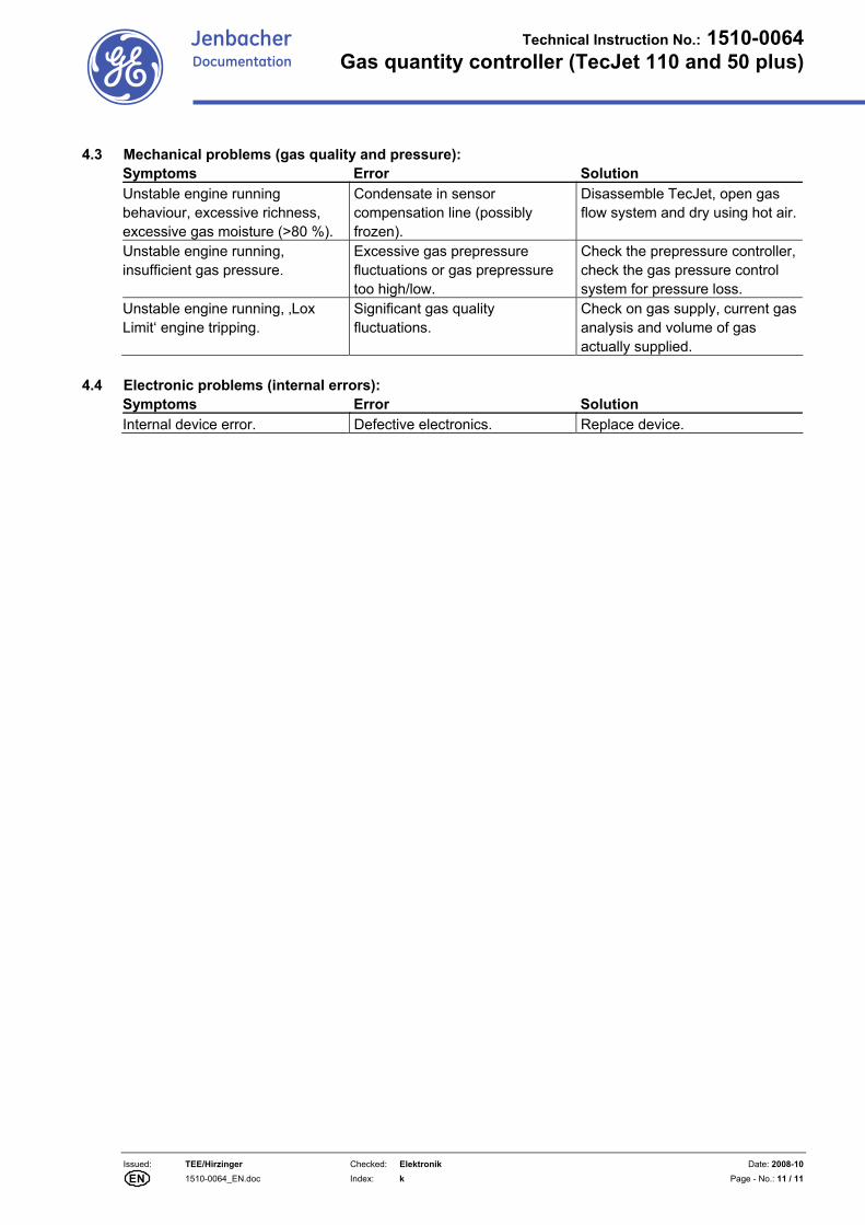
4.3 Mechanical problems (gas quality and pressure): Symptoms Error Solution Unstable engine running behaviour, excessive richness, excessive gas moisture (>80 %).
Condensate in sensor compensation line (possibly frozen).
Disassemble TecJet, open gas flow system and dry using hot air.
Unstable engine running, insufficient gas pressure.
Excessive gas prepressure fluctuations or gas prepressure too high/low.
Check the prepressure controller, check the gas pressure control system for pressure loss.
Unstable engine running, ‚Lox Limit‘ engine tripping.
Significant gas quality fluctuations.
Check on gas supply, current gas analysis and volume of gas actually supplied.
4.4 Electronic problems (internal errors):
Symptoms Error Solution Internal device error. Defective electronics. Replace device.
![A Blind Adaptive SOR/JGS Iterative Kalman MUD Algorithm ...Jacobi Gauss-Seidel (JGS) iteration algorithm [14] make it possible to achieve accurate real-time control for MUD algorithm](https://img.dokumen.tips/doc/110x75/5f20403e4df38c60df5a4b57/a-blind-adaptive-sorjgs-iterative-kalman-mud-algorithm-jacobi-gauss-seidel.jpg)


![oSQls djsa dgkuh dk ukV~; :ikarj · Hkkx&nkSM+ dj jgs gSa] rS;kj gks jgs gSa] ckj&ckj vius iSls fxu jgs gSa vkSj Vksyh osQ fudyus dh jkg ns[k jgs gSaA igys n`'; dk vafre fgLlk gkfen](https://img.dokumen.tips/doc/110x75/6081d10f312c154fd4046e51/osqls-djsa-dgkuh-dk-ukv-ikarj-hkkxnksm-dj-jgs-gsa-rskj-gks-jgs-gsa-ckjckj.jpg)


![khHkwr djus eas leFkZ jgs gSaA e/kqj Hkk’k.k]](https://img.dokumen.tips/doc/110x75/628cb14c4e704333eb714d9c/khhkwr-djus-eas-lefkz-jgs-gsaa-ekqj-hkkkk.jpg)

