Embed Size (px)
DESCRIPTION
NMS
Citation preview

From SNMP to Web services-basednetwork management.
Jeroen van Sloten
Thesis for a Master of Science degree in
Computer Science from the University of
Twente, Enschede, the Netherlands
Graduation committee:
Dr.ir. A. Pras
Dr.ir. M.J. van Sinderen
Enschede, the Netherlands
4th June 2004

i

Abstract
One of the emerging standards for application to application inter-action and therefore for the interconnection of (distributed) systemsis Web services. It is an open, generic and standardised XML-basedtechnology and has recently received a wide industry attention. Con-sidering the current interest of network management research groupsin XML-based technologies, Web services need investigation for itssuitability for network management. This is therefore the main ob-jective of this thesis.
This thesis presents some of the characteristics of Web services thatmake it useful to use for network management. Furthermore, anoverview of additional Web service standards that are expected tobe of interest for network management is presented.
Standardisation plays an important role in the adoption of a net-work management technology. This thesis distinguishes which partsof a Web service are suitable for standardisation. Within these partsthere is room for variation, and therefore the merits of various alter-natives are discussed.
The Model-Driven Architecture (MDA) is an approach that pro-motes the usage of modelling for the design of (software) systems.Models should be used at different levels of abstraction, thus creat-ing a clear separation between the specification of the functionalityof a system and the implementation of this functionality on a spe-cific platform. Since Web services can be implemented on a varietyof platforms, this thesis explains why MDA can play an importantrole for the development of Web services in general and networkmanagement in particular.
ii

iii

Acknowledgements
From September 2003 to June 2004 I have carried out the final stage of myComputer Science study at the University of Twente. I have spent these ninemonths performing research on the use of Web services for network management,the result of which is presented in this Master’s thesis.
My thanks and gratitude go to all the people from whom I have receivedenormous amounts of help and support while performing my research project.First and foremost I would like to thank my supervisors Aiko Pras and Martenvan Sinderen, who have provided me with all the necessary help that provedvaluable for this project. They have pointed me in the right direction whenneeded and especially they made the conversations we have had very pleasantand interesting.
Thanks also go to all my colleagues and fellow students from the ARCH groupwho have provided me with new insights, the necessary distraction from timeto time and most of all a pleasant working environment.
Also I wish to thank my family and friends who have all been very supportiveand highly inspiring, not only during my Master’s project, but throughout myentire study.
And last but not least my deepest gratitude goes to Yongjun, my partnerfor life. She has been a great help for me, for her expertise, but especially forshowing her heartfelt encouragement and continuous support. She has showngreat patience while waiting for me to finish this thesis. Above all she has givenme her endless love which is the greatest support of all.
Jeroen van Sloten
EnschedeJune, 2004
iv

v
Contents
Acknowledgements iv
List of Figures ix
List of Tables x
1 Introduction 1
1.1 Background . . . . . . . . . . . . . . . . . . . . . . . . . . . . . . 11.1.1 Towards XML-based network management . . . . . . . . 11.1.2 Web services-based network management . . . . . . . . . 21.1.3 Model-Driven Architecture . . . . . . . . . . . . . . . . . 2
1.2 Problem description . . . . . . . . . . . . . . . . . . . . . . . . . 31.3 Scope and objectives . . . . . . . . . . . . . . . . . . . . . . . . . 31.4 Approach . . . . . . . . . . . . . . . . . . . . . . . . . . . . . . . 41.5 Related work . . . . . . . . . . . . . . . . . . . . . . . . . . . . . 5
1.5.1 Network Management Research Group . . . . . . . . . . . 51.5.2 NetConf . . . . . . . . . . . . . . . . . . . . . . . . . . . . 51.5.3 Web-Based Enterprise Management . . . . . . . . . . . . 61.5.4 Web Services Management Framework . . . . . . . . . . . 61.5.5 Other . . . . . . . . . . . . . . . . . . . . . . . . . . . . . 6
1.6 Intended audience . . . . . . . . . . . . . . . . . . . . . . . . . . 71.7 Structure . . . . . . . . . . . . . . . . . . . . . . . . . . . . . . . 8
2 State of the art 9
2.1 Simple Network Management Protocol . . . . . . . . . . . . . . . 92.1.1 Foundation . . . . . . . . . . . . . . . . . . . . . . . . . . 92.1.2 Architecture . . . . . . . . . . . . . . . . . . . . . . . . . 102.1.3 Management Information Base . . . . . . . . . . . . . . . 112.1.4 SNMP protocol operations . . . . . . . . . . . . . . . . . 13
2.2 Web Services . . . . . . . . . . . . . . . . . . . . . . . . . . . . . 162.2.1 Basic concepts . . . . . . . . . . . . . . . . . . . . . . . . 162.2.2 Web Service Description Language . . . . . . . . . . . . . 19
2.3 Model-Driven Architecture . . . . . . . . . . . . . . . . . . . . . 212.3.1 Introduction . . . . . . . . . . . . . . . . . . . . . . . . . 212.3.2 Basic concepts . . . . . . . . . . . . . . . . . . . . . . . . 222.3.3 Model transformation . . . . . . . . . . . . . . . . . . . . 24
vi
3 Web services for network management 26
3.1 Performing network management with Web services . . . . . . . 263.2 Message exchange patterns . . . . . . . . . . . . . . . . . . . . . 293.3 Interface extensibility . . . . . . . . . . . . . . . . . . . . . . . . 323.4 Additional Web service standards . . . . . . . . . . . . . . . . . . 33
3.4.1 Security . . . . . . . . . . . . . . . . . . . . . . . . . . . . 333.4.2 Transactions . . . . . . . . . . . . . . . . . . . . . . . . . 343.4.3 Reliability . . . . . . . . . . . . . . . . . . . . . . . . . . . 343.4.4 Summary . . . . . . . . . . . . . . . . . . . . . . . . . . . 34
4 Standardisation 36
4.1 WSDL modularisation . . . . . . . . . . . . . . . . . . . . . . . . 364.2 Management operations . . . . . . . . . . . . . . . . . . . . . . . 38
4.2.1 Operation definition extremes . . . . . . . . . . . . . . . . 384.2.2 Parameter transparency . . . . . . . . . . . . . . . . . . . 394.2.3 Operation granularity . . . . . . . . . . . . . . . . . . . . 424.2.4 Summary . . . . . . . . . . . . . . . . . . . . . . . . . . . 44
4.3 Management information definition . . . . . . . . . . . . . . . . . 454.3.1 Data models and information models . . . . . . . . . . . . 454.3.2 Management information models . . . . . . . . . . . . . . 464.3.3 Data-oriented information model . . . . . . . . . . . . . . 474.3.4 Object-oriented information model . . . . . . . . . . . . . 514.3.5 Summary . . . . . . . . . . . . . . . . . . . . . . . . . . . 52
5 Case study: host-resources 53
5.1 Host-Resources MIB . . . . . . . . . . . . . . . . . . . . . . . . . 535.2 Data-oriented approach . . . . . . . . . . . . . . . . . . . . . . . 54
5.2.1 Information model . . . . . . . . . . . . . . . . . . . . . . 555.2.2 Protocol . . . . . . . . . . . . . . . . . . . . . . . . . . . . 555.2.3 Summary . . . . . . . . . . . . . . . . . . . . . . . . . . . 57
5.3 Object-oriented approach . . . . . . . . . . . . . . . . . . . . . . 575.3.1 Information model . . . . . . . . . . . . . . . . . . . . . . 585.3.2 Protocol . . . . . . . . . . . . . . . . . . . . . . . . . . . . 595.3.3 Summary . . . . . . . . . . . . . . . . . . . . . . . . . . . 62
6 Conclusions 64
6.1 Main contributions . . . . . . . . . . . . . . . . . . . . . . . . . . 646.2 Future work . . . . . . . . . . . . . . . . . . . . . . . . . . . . . . 67
A SNMPv2-PDU definitions 69
B Host-resources database model diagram 72
C SNMP-WS abstract interface definition 74
D SNMP-WS binding definition 76
E snmp-simple.xsd 78
F Generated Host-Resources UML class diagram 80
vii

G Revised Host-Resources UML class diagram 82
H Generated WSDL for hrDeviceEntry 84
Bibliography 87
viii

List of Figures
1.1 Thesis structure . . . . . . . . . . . . . . . . . . . . . . . . . . . . 8
2.1 SNMP basic operation . . . . . . . . . . . . . . . . . . . . . . . . 102.2 SNMP network stack . . . . . . . . . . . . . . . . . . . . . . . . . 112.3 SNMP naming tree . . . . . . . . . . . . . . . . . . . . . . . . . . 122.4 Conceptual table: ifTable (Interfaces MIB) . . . . . . . . . . . . 132.5 SNMP message and PDU formats (taken from [1]). . . . . . . . . 142.6 SNMPv2 PDU sequences (taken from [1]). . . . . . . . . . . . . . 152.7 Web service: weather service . . . . . . . . . . . . . . . . . . . . 172.8 Web services communication . . . . . . . . . . . . . . . . . . . . 172.9 SOAP message structure . . . . . . . . . . . . . . . . . . . . . . . 182.10 Web services architecture . . . . . . . . . . . . . . . . . . . . . . 192.11 Modelling abstraction levels . . . . . . . . . . . . . . . . . . . . . 232.12 MDA model transformation . . . . . . . . . . . . . . . . . . . . . 24
3.1 Principle operation of WS-based network management . . . . . . 273.2 Simplified network layer stack . . . . . . . . . . . . . . . . . . . . 283.3 WSDL message exchange patterns. . . . . . . . . . . . . . . . . . 303.4 Web service related standards . . . . . . . . . . . . . . . . . . . . 35
4.1 WSDL import mechanism . . . . . . . . . . . . . . . . . . . . . . 384.2 Operation extremes . . . . . . . . . . . . . . . . . . . . . . . . . . 394.3 Containment diagram . . . . . . . . . . . . . . . . . . . . . . . . 424.4 Containment tree . . . . . . . . . . . . . . . . . . . . . . . . . . . 434.5 Management IM and DMs . . . . . . . . . . . . . . . . . . . . . . 464.6 System information ER diagram . . . . . . . . . . . . . . . . . . 504.7 IfTable ER diagram . . . . . . . . . . . . . . . . . . . . . . . . . 51
5.1 Simplified Host-resources UML class diagram . . . . . . . . . . . 595.2 hrDeviceEntry class definition. . . . . . . . . . . . . . . . . . . . 60
ix
List of Tables
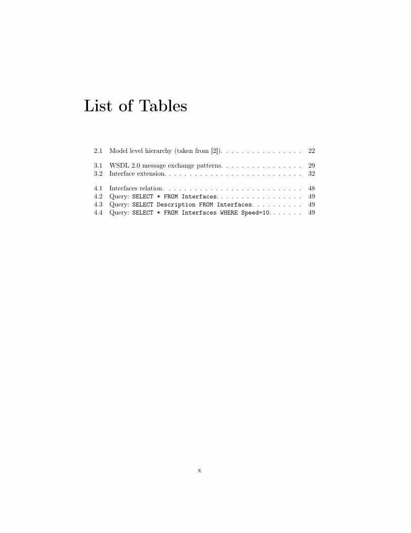
2.1 Model level hierarchy (taken from [2]). . . . . . . . . . . . . . . . 22
3.1 WSDL 2.0 message exchange patterns. . . . . . . . . . . . . . . . 293.2 Interface extension. . . . . . . . . . . . . . . . . . . . . . . . . . . 32
4.1 Interfaces relation. . . . . . . . . . . . . . . . . . . . . . . . . . . 484.2 Query: SELECT * FROM Interfaces. . . . . . . . . . . . . . . . . 494.3 Query: SELECT Description FROM Interfaces. . . . . . . . . . 494.4 Query: SELECT * FROM Interfaces WHERE Speed=10. . . . . . . 49
x

Listings
2.1 WSDL example . . . . . . . . . . . . . . . . . . . . . . . . . . . . 202.2 Endpoints . . . . . . . . . . . . . . . . . . . . . . . . . . . . . . . 203.1 MEP: In-Only . . . . . . . . . . . . . . . . . . . . . . . . . . . . . 313.2 MEP: Robust In-Only . . . . . . . . . . . . . . . . . . . . . . . . 313.3 MEP: In-Out . . . . . . . . . . . . . . . . . . . . . . . . . . . . . 323.4 Interface extension . . . . . . . . . . . . . . . . . . . . . . . . . . 334.1 Import of interface WSDL . . . . . . . . . . . . . . . . . . . . . . 374.2 Multiple message parts with simple types . . . . . . . . . . . . . 404.3 Single message parts with opaque types . . . . . . . . . . . . . . 404.4 Single message parts with complex types . . . . . . . . . . . . . . 414.5 Multiple message parts with simple and complex types . . . . . . 425.1 SNMPv2-style operations . . . . . . . . . . . . . . . . . . . . . . 565.2 SNMPv2-style messages . . . . . . . . . . . . . . . . . . . . . . . 565.3 VarBindList type definition (SMI) . . . . . . . . . . . . . . . . . 575.4 VarBindList type definition (XML Schema) . . . . . . . . . . . . 585.5 hrDeviceEntry WSDL: operations . . . . . . . . . . . . . . . . . . 615.6 hrDeviceEntry WSDL: messages . . . . . . . . . . . . . . . . . . 62
xi

Chapter 1
Introduction
This chapter provides an insight in the background of this research project anda detailed description of the problems that will be tackled. This is followed byan overview of the approach, related work and intended audience.
1.1 Background
Ever since the introduction of computer networks, there has been an interestin management functionality. In the early days of computer networks simpleapplications such as ping and traceroute were sufficient to find congestions inthe network for instance. But as the complexity of networks rises and networksbecome more and more interconnected, the need for more complex managementfunctionality is also growing. By the end of the eighties the development ofnetworks and simple management tools eventually led to management standardssuch as the Simple Network Management Protocol (SNMP).
Since then, SNMP, in its different versions [3], has grown to be the most com-monly used network management platform in IP networks. However, while orig-inally developed in an environment where networks were small, bandwidth wasscarce and processing power on networked devices was low, the design choicesmade then are nowadays becoming apparent limitations in the network man-agement area.
1.1.1 Towards XML-based network management
SNMP is based on the manager-agent paradigm. For the exchange of messagesSNMP relies on UDP [4], which is, according to many, a cause of great concern[5, 6]. Originally agents were meant to be as simple as possible, with most ofthe processing and control done at the manager-side. But times have changedand current devices are powerful enough to perform more complex managementoperations also at the agent side [7]. Furthermore, SNMP is a domain-specificprotocol that, despite its name, is not easy to use. Integration with existing soft-ware is difficult and only a limited number of experts have sufficient knowledgeto develop new management applications [7]. Because of these limitations thereis nowadays a trend towards more generic technologies to be used for networkmanagement. One of the main technologies being investigated is the eXten-
1

CHAPTER 1. INTRODUCTION 2
sible Markup Language (XML) [8]. Current efforts in improving IP networkmanagement are mostly based on dedicated XML formats [9, 10].
These problems have also been the topic of discussion within the InternetEngineering Task Force (IETF) [11], the Network Management Research Group(NMRG) [12] of the Internet Research Task Force (IRTF) [13] and the Inter-net Architecture Board (IAB) [14]. The IAB, for example, organised a specialworkshop in June 2002 to discuss the future of network management (RFC3535[15]). Many attendees at that meeting expected that the so-called evolution-ary approaches would fail and that more focus should be put on revolutionaryapproaches, most notably approaches that are XML-based [7]. This outcome,combined with the fact that there has not been substantial output yet, hasmade for ongoing IETF workgroups such as Evolution of SNMP (EoS) [16] andSMING [17] to be discontinued. Meanwhile, there are even those who state thatstandardisation of network management protocols should move from the IETFto the World Wide Web Consortium (W3C) [18], partly because of this focusshift towards XML [19] which is a W3C standard itself.
1.1.2 Web services-based network management
An emerging standard based upon XML is Web services [20]: an open, genericand standardised technology for the interconnection of computer systems. Be-cause it is XML-based it is in principle platform and programming languageindependent. One can currently notice an industry-wide interest in Web ser-vices, supported by the growing availability of various related application serversand development tools. Web services are expected to become a standard part offuture operating systems and application servers, which will result in a growingfamiliarity among many users and developers. All these characteristics make itto be a very promising technology for (distributed) computer systems.
The availability, combined with being a generic technology and an openstandard, makes it easier for people to develop applications using Web services.Apart from dedicated management applications, one can also think of presentingmanagement information in a spreadsheet or storing management information indatabases simply by calling a Web service for which support is already present inthe operation system. SNMP also makes clear that availability of applications isa key factor for the market acceptance of a technology [7]. But these advantagesof Web services are very general and not only relevant to network management.What is very important for network management is that there is a standardisedform in which management information is defined and how this informationis accessed [19]. It remains hard to develop a management application whenmanagement information and its accessor operation are not standardised.
1.1.3 Model-Driven Architecture
When legacy technologies and systems are concerned, one can think of a newconcept that is rapidly evolving in the software engineering field: Model-DrivenArchitecture. It is proposed by the Object Management Group (OMG) [21]to bring the design of (software) systems to a higher level of abstraction thandesign at programming code level, by making more active use of modelling andtransformations between models. MDA makes a clear separation between the

CHAPTER 1. INTRODUCTION 3
specification of a system’s functionality and its implementation on a particularplatform [22].
The reason why this can be interesting for legacy systems is that it enables asoftware engineer to capture the functionality of such a system in a higher-levelmodel. This creates an abstraction from the legacy technologies that a systemis usually built on. Furthermore, with MDA it should then be possible todeploy a system with similar functionality and behaviour on a platform basedon a different technology. More concretely, in case of SNMP-based networkmanagement it can be highly interesting to capture its functionality in a modelthat is not dependent on SNMP-based technologies.
Web services can be implemented on a variety of platforms, however somebasic design issues could possibly be very similar for each platform. This is atypical area where MDA is expected to be useful.
1.2 Problem description
Since Web services is a relatively new standard, little is known about applyingit for network management. There is already an interest by standardisationorganisations and research groups [7] in XML-based approaches, but researchthusfar focussed on dedicated XML-based approaches [9, 10], rather than genericapproaches like Web services. This is why it is of great importance to acquiremore knowledge on how Web services can be applied for this specific task.
Currently, XML-based Web service standards are appearing as a more genericapproach towards systems interconnection. They can already be used on awide variety of platforms (Microsoft .NET, Java platforms, etc.). Web ser-vices offer quite similar concepts as SNMP, such as invoking operations on re-mote systems, communication through message exchange and implementation-independent service descriptions.
Sceptics often use the argument of poor performance compared to existingSNMP implementations, when discussing Web service-based (or other XML-based) protocols [23]. It is quite obvious that XML documents can get veryverbose and most certainly it is a reason for concern. However important stepsin comparing SNMP and Web service performance have already been made andthe results look very promising (see section 1.5.5) and are certainly reasons fordoing more research in this area.
1.3 Scope and objectives
The main objective of this thesis is to investigate how Web services can beapplied for network management. This makes it important to first identify apossible Web services-based management architecture and to get feeling withthe concepts. The characteristics of Web services that are of particular interestfor network management need to be described.
In order for a network management approach to be adopted widely, stan-dardisation needs to take place. For Web services this means that those partsthat are suitable for standardisation need to be identified. An issue related tostandardisation is the definition of management operations and correspondingmessages. There can be a wide variety of operations, so it is important to recog-

CHAPTER 1. INTRODUCTION 4
nise which forms there possibly are and what the merits of each of those formsare.
Finally, applying MDA tools to aid in the development of network manage-ment Web services will be discussed. Given the fact that network managementdata models are standardised (for instance SNMP’s data model) and the model-oriented nature of MDA, MDA could be a very useful methodology for easily de-veloping management applications for different types of Web service-platforms.
These objectives lead to the following research questions:
• Why are Web services suitable to use for management of IP networks?
• Which parts of Web services need to be standardised for Web services-based network management?
• What possible forms can management operations take and what are theirmerits?
• Which role can MDA tools play for developing Web Services-based man-agement applications?
It is not the intention of this thesis to do another performance comparisonbetween SNMP and Web services, nor will it propose a gateway or dual stacksolution. As mentioned before, research is already being performed in theseareas. It is also not the intention to propose a new standard for network man-agement based on Web services. Furthermore, the goal is also not to discussthe management information itself. This thesis will be based upon SNMP andtherefore also the management information comprised in SNMP data models.The reader who is interested in the different data models is referred to the studypresented by López de Vergara et. al. [24], which gives an interesting discus-sion on which management information should be available and what the bestdefinition language is.
1.4 Approach
The following approach will be adopted in this thesis:
1. give a state of the art of SNMP, Web services and MDA. This includesthe SNMP management architecture, the protocol and the data definitionlanguage. Furthermore, the concept of Web services shall be explainedwith a focus on the Web Services Description Language. And finally, themain concepts of the Model-Driven Architecture will be introduced.The goal of this step is to make the reader acquainted with the technologiesthat are being discussed in this thesis as well as the related terminology.
2. describe the characteristics of Web services and explain why they are suit-able to perform network management.The goal is to understand how Web services can be applied for networkmanagement.
3. determine which parts of Web services can and need to be standardised.This will focus mainly on the description of Web services, by introducingan explanation on the modularity of WSDL documents, followed by an

CHAPTER 1. INTRODUCTION 5
elucidation on management operations.The goal of this step is to understand which parts of a Web service canbe used for network management standardisation and what variations arepossible within these parts.
4. illustrate the discussed topics by means of a case study where the SNMPHost-resources MIB shall be migrated to a Web service environment. Thiswork will be carried out by means of an MDA development tool.The goal is to show how Web services-based network management couldwork in practice and to gain experience with the suitability of MDA toolsin the development of Web services.
1.5 Related work
There are several initiatives in the field of network management that focus onWeb services or provide very similar functionality. They will be discussed inthis section.
1.5.1 Network Management Research Group
The Network Management Research Group is a small group of researchers for"exploring new technologies for the management of the Internet" [12]. TheNMRG is a research group of the IRTF [13] and is responsible for the advancesmade with SNMP, SMI and other related topics after its installation in 1999.
The NMRG needs mentioning here, because of its contribution to SNMPand its current interest in investigating XML related technologies, most notablyin Web services.
1.5.2 NetConf
NetConf [25] is a Working Group of the IETF [11] and chartered to producea protocol suitable for network configuration. Configuration typically entailsrelatively simple tasks such as up- or downloading whole configurations. Ittherefore needs only a few basic operations to transfer large amounts of data.The NetConf protocol offers a small set of coarse operations to manage de-vice configurations and retrieve device state information. However, these set ofcoarse operations is meant to be extensible with finer operations when specificfunctionality is required. But considering the expected usage of coarse oper-ations, there is no need for standardising finer operations. Communication isperformed through the exchange of NetConf-specific XML messages. Due tothe wide interest in the more generic SOAP messaging (SOAP is explained insection 2.2) the NetConf WG has acknowledged that it is definitely interest-ing to investigate its usability for NetConf [26]. SOAP offers the functionalitythat is required, but more important it is widely supported on many platformsand used, almost without exception, as the message standard for Web services.NetConf could therefore possibly be used as a Web service.

CHAPTER 1. INTRODUCTION 6
1.5.3 Web-Based Enterprise Management
For the last several years, the Distributed Management Task Force [27] has beendeveloping an information model for a managed environment, called CommonInformation Model [28]. CIM is an object-oriented conceptual view of the man-aged environment, unlike SNMP, which is a data-oriented model and protocol.The CIM does not include only some generic properties of networked devices,like many standardised SNMP MIBs, but it attempts to provide a very compre-hensive and detailed view of a managed system. Naturally this results in a largecollection of objects. These objects are defined textually in the Managed ObjectFormat (MOF) [29], but are also presented in a (non-normative) graphical form.
The CIM is part of the Web-Based Enterprise Management (WBEM) initia-tive. WBEM is "a set of management and Internet standard technologies devel-oped to unify the management of enterprise computing environments". Apartfrom the CIM, it also includes a protocol for transporting management data(CIM Operations over HTTP) and an encoding specification (xmlCIM Encod-ing Specification) that is used to represent CIM classes and instances.
1.5.4 Web Services Management Framework
Hewlett Packard [30] has developed a logical architecture for managing com-puting resources through Web services. This is called The Web Services Man-agement Framework (WSMF) which is now adopted by OASIS [31]). It hasbeen developed to address the growing need of businesses to integrate their sys-tems, and more specifically the management of those systems. The frameworkprovides a collection of interfaces that expose a certain type of managementinformation for so-called managed objects. Each interface has operations thatare related to a specific task, such as monitoring, discovery or configuration.The WSMF allows for interfaces to be extended and new interfaces to be addedfor managed objects.
The aim of the WSMF is to provide a generic, platform independent interfaceto management information. The operations provided by the interfaces that arestandardised, are generally very fine operations which serve a specific task. Theidea is to use the extensibility of Web services to specify more non-standardisedoperations when needed. Another idea is that, since common interfaces providecommon operations, one single interface (and thus its operations) can also beused for a collection of managed objects.
1.5.5 Other
Gateway solutions
Some groups try to find solutions to incorporate SNMP with dedicated XMLsolutions and even already a Web services-based management approach: so-called gateway solutions. These architectures mostly consist of SNMP agents,XML-based managers and an XML to SNMP request translator. Because theyare not Web service-based they will not be further discussed here, but sincethey cover a similar area of research they are worth mentioning as related work.Main research in this area takes place on the Pohang University of Science andTechnology in South-Korea [9], the Technical University of Braunschweig inGermany [10] and the Federal University of Rio Grande do Sul in Brazil [32].

CHAPTER 1. INTRODUCTION 7
Performance
Poor performance is a commonly heard argument by critics of Web service-basednetwork management. One important reason is that Web services are based onXML and XML documents have the tendency to get rather verbose. Currentlyundergoing research on the comparison of SNMP and Web services seems verypromising for Web services though.
First of all, work carried out at the University of Twente [33] has focussedon comparing bandwidth and resource usage of SNMP and Web services withregard to network monitoring (management data retrieval). SNMP and Webservices have been tested both with and without using data compression. Theresults of these comparisons are very promising as they show that Web servicesdo not perform much worse than SNMP. In fact, in some cases it performs evenbetter, like when large amounts of data are concerned. With small amountsof data (which is the typical usage of SNMP), SNMP does generally performbetter than Web services.
Ricardo Neisse et al. [32] introduce the idea of defining operations on differ-ent levels of granularity instead of merely copying the SNMP primitives. In thisSNMP to Web services gateway, operations are defined on a so-called protocol-level or on an object-level. Operations on protocol-level are translations ofSNMP primitives: Get, GetNext and Set, whereas on the object-level there isa specific Get method for each scalar and table object, such as GetSysLocationor GetIfTable. A Set method is created for each writable object, i.e. SetSysLo-cation or SetIfAdminStatus. So the protocol-level gateway has a few operationswith very coarse granularity, whereas the object-level gateway supports onlyoperations with very fine granularity. The incentive of this research project wasto conduct a bandwidth comparison between the gateway fine coarse operationsand the gateway with fine operations. The result of this comparison was thatprotocol-level gateways are only interesting when just a few SNMP objects areconcerned. This type of gateway uses SNMP object identifiers and the SNMPstyle of communication: a response message for each single value. The object-level gateway reduces network traffic, because it can send collected managementinformation back to the manager in one SOAP message. This turns out to bemore efficient with a high number of instances (this number varies for com-pressed or uncompressed messages and for SOAP over HTTP or over HTTPS).Therefore an object-level gateway is of particular interest for configuration man-agement, where typically large amounts of information is transferred.
1.6 Intended audience
This report is written for computer scientists, network specialists and otherpeople with a background in network management and more specifically SNMP.The reader is expected to have some basic understanding with concepts such asWeb Services, WSDL and MDA and more profound knowledge on SNMP, MIBsand possibly SMI. These standards will be explained here rather briefly.

CHAPTER 1. INTRODUCTION 8
1.7 Structure
This report is structured according to the steps defined in the approach (section1.4). Step 1 relates to chapter 2 that presents the state of the art of SNMP,Web services and MDA. The next step relates to chapter 3 that describes howWeb services can be applied for network management. Chapter 4 identifieswhich parts of a Web service can be used for network management standardis-ation and what variations are possible within these parts. Chapter 5 illustratesseveral Web service concepts with a case study on the migration of the Host-resources MIB to Web services-based network management. Finally, conclusionsare drawn and recommendations are given in chapter 6. This structure is de-picted in figure 1.1.
Chapter 2
State of the art
Chapter 6
Conclusions
Chapter 5
Case study: host-
resources
Chapter 4
Standardisation
Chapter 3
Web services for
network
management
Chapter 1
Introduction
Approach
step 1
Approach
step 2
Approach
step 3
Approach
step 4
Figure 1.1: Thesis structure

Chapter 2
State of the art
This chapter presents the state of the art of the main technologies that arerelevant to the research questions. Firstly, section 2.1 provides an introductionto the Simple Network Management Protocol and describes its basic concepts.Section 2.2 explains what Web services actually are and gives a detailed overviewof the Web Service Description Language. This chapter concludes with section2.3 on the Model-Driven Architecture.
2.1 Simple Network Management Protocol
2.1.1 Foundation
In the early years of small networks (roughly until the mid-eighties), small ap-plications as ping and traceroute were powerful enough to provide basic man-agement functionality. But with the exponential growth of networks since thelate eighties, the need arose for a management protocol with much more func-tionality. Several approaches were evaluated and finally SNMP was selected asa short-term solution, because of its simplicity. In the long-term it was thoughtto make way for a different, more elaborate management protocol which was tobe part of the OSI model [34].
Being a part of the TCP/IP suite, SNMP followed a similar developmentas TCP/IP. Both were thought to be simple and short-term solutions, as theywould in the future be replaced by the OSI standards. However, since theyexperienced a vast deployment in rapid growing networks, both protocols out-lasted their lifetimes by far. In fact, they are still widely used nowadays and theOSI models remain reference models. To date, almost all vendors of computers,bridges, routers, etc. offer SNMP support for their products.
SNMPv1 was released in 1989 followed by a proposal for version SNMPv2 in1993 and a revision of this version in 1995. Then in 1998 SNMPv3 was issued,which experienced a big focus shift to security. It extends both SNMPv1 andSNMPv2. All of these versions are extensions of the following three foundationspecifications [1, p.75]:
• Structure and Identification of Management Information for TCP/IP-based networks (RFC 1155 [35]).
9

CHAPTER 2. STATE OF THE ART 10
• Management Information Base for Network Management of TCP/IP-basedInternets: MIB-II (RFC 1213 [36]).
• Simple Network Management Protocol (RFC 1157 [37]).
2.1.2 Architecture
The SNMP network management architecture makes a clear distinction betweenthe roles of SNMP-enabled networked devices and systems. A managementagent is a device or system that is being managed and a management station isa system from which agents are managed. A management station is sometimesalso referred to as a manager.
The architecture also defines a management protocol, that provides the linkbetween the managers and agents. Management information itself is standard-ised and defined in the form of Management Information Bases (MIB). If anagent is said to support a certain MIB, the manager consequently knows howto address the agent in order to access information defined in this MIB. Theoverall SNMP network management architecture is depicted in figure 2.1.
Many networked devices, such as PC’s, routers, printers, hubs, switches,etc. can contain an SNMP agent. A manager is the interface for a humannetwork operator to monitor and configure these networked devices. Thereforemostly a PC or workstation contains a manager, since these are able to present a(graphical) user interface to the operator. These systems itself can also containan agent, allowing a management application to also manage the system it isrunning on. Typical applications on a manager include data analysis and faultrecovery. A manager could for instance also be connected to a database system,in order to periodically store management information for statistical purposes.
A management agent in its turn, is able to retrieve the actual data fromthe device it is running on. An agent either waits for requests from a manager,or it can initiate action by sending a so-called trap to the manager. Agentsand managers are able to communicate with each other by means of SNMPprimitives, as defined by the SNMP protocol. The key capabilities that theseprimitives offer are to get and set management information from an agent by amanager, and to send trap notifications from an agent to a manager. Traps areused to inform a manager of unusual events that have occurred on the agent-
Manager
SNMP
Trap
SNMP Request
SNMP Response
SNMP Agent
MIB MIB
SNMP Agent
3 C o m
MIB MIB
SNMP Agent
MIB MIB
Figure 2.1: SNMP basic operation

CHAPTER 2. STATE OF THE ART 11
Network-dependent protocol
IP
UDP
SNMP
Manager / agent
process
Figure 2.2: SNMP network stack
side, such as a reboot after a crash of the system, a link that is down or somepre-defined condition that is fulfilled. For instance, if the agent notices that thepercentage of TCP error packets of the total amount of TCP packets is abovea certain level, it can notify the manager by means of a trap.
SNMP is designed to be a part of the TCP/IP protocol suite. Its intendeduse is on top of the User Datagram Protocol (UDP) [4], because UDP is con-nectionless. This would allow a management application to be in full controlof retransmission strategies, in case connections are lost or congestions haveoccurred [7]. Also it does not have a lot of protocol overhead. The datagramheaders that need to be created are very small, compared to TCP for instance,which limits the size of the datagrams [5]. Within the IETF, there has been anattempt to use SNMP on top of TCP [38], but this is still experimental. Figure2.2 shows examples of the SNMP protocol stack which should be existent onboth a manager and an agent.
Each manager and each agent must at least implement IP, UDP and SNMP.This excludes any networked device that does not implement the TCP/IP stackfrom being managed by SNMP. There are provisions however, to create so-calledproxy agents in order to translate SNMP requests to a different managementprotocol and vice versa. The SNMP agent in this case maintains the manage-ment information on behalf of one or more non-SNMP devices.
2.1.3 Management Information Base
Resources in a networked device are defined as managed objects. This conceptof an object should not be confused with the concept that is commonly knownfrom object-oriented programming. These are not the same. In fact, a managedobject is merely a data variable representing one aspect of a resource. Forexample, suppose a router is a resource, then the system uptime would be oneaspect of the router. Thus "system uptime" could be called a managed objectin SNMP terminology.
A collection of managed objects that are in some way related to each otherare grouped together in a structured format called a Management InformationBase, also called a MIB module or a MIB. A formal definition of a MIB moduleis the following [39]:
"MIBs are specifications containing definitions of management in-formation so that networked systems can be remotely monitored, con-figured and controlled."

CHAPTER 2. STATE OF THE ART 12
ccitt (0) iso (1) joint-iso-ccitt (2)
standard (0) registration-
authority (1)
member-
body (2)
identified-
organization (3)
dod (6)
internet (1)
directory (1) mgmt (2) experimental (3) private (4) security (5) snmpv2 (6)
mib-2 (1)
system (1) interface (2) ip (4)
sysObjectID (2)
sysUpTime (3) sysDescr (1)
... ... ... ...
...
...
... ...
...
...
...
Figure 2.3: SNMP naming tree
The main objective of a MIB is to enhance interoperability across networkeddevices. One way this is accomplished is to have managed objects representinga particular resource the same at each system. For instance, a managed objectrepresenting the system uptime on one system, should have the same name andfunction on another system. It would be a great cause of confusion when, forexample, one system would regard it as the time elapsed since the last reboot,and another system regards it as the time elapsed since the operating systemwas installed regardless of any reboots. Such a situation is not feasible of course.
A second way to enhance interoperability is to have a common definitionlanguage for the representation of MIBs: the Structure of Management Infor-mation (SMI) [35]. SMI is based on the ASN.1 notation, but uses only a verysmall subset of it for the sake of simplicity. SMI identifies only several basic datatypes and specifies how resources are represented and named. New types canbe defined based on the basic types, but they can only be either scalars (basedon integer, octet string, null or object identifier) or two-dimensional arrays ofscalars (with sequence and sequence of ). This rules out all possibilities for morecomplex data structures.
Managed objects are arranged hierarchically in a tree structure, where eachleaf represents a managed object. All nodes and leafs in the tree are given apermanent number, so that each managed object can be uniquely identified ona single networked device by a sequence of these numbers: the object identifier(OID). This OID is defined in a MIB where the corresponding managed objectis also defined. An example of (a part of) the SNMP naming tree is given infigure 2.3.
If for instance someone wants to retrieve the system uptime of a certainnetworked device, it has to provide the corresponding OID to the get primitive.The OID represents the place of the system uptime variable in the namingtree. Starting from the root, the following path should be followed to reach this

CHAPTER 2. STATE OF THE ART 13
ifTable
ifEntry
ifEntry
ifEntry
...
ifIndex ifDescr ifType ifMtu ifSpeed ...
Figure 2.4: Conceptual table: ifTable (Interfaces MIB)
variable:
iso → org → dod → internet → mgmt → mib-2 →
system → sysUpTime
When the names of the nodes are replaced by the node number, the followingOID is retrieved:
1.3.6.1.2.1.1.3
If this OID is provided with the SNMP get primitive, the addressed agent re-trieves this value from the system it is running on and sends it to the managerin a response message.
Two-dimensional arrays are a very simple way (in fact the only way in SMI)of structuring data. It allows for the creation of conceptual tables: they appearas tables, but they can only be addressed cell by cell. Such a table consistsof instances of a certain row object-type. For example, the Interfaces MIB [40]defines an ifEntry object-type. ifEntry itself is a sequence of scalar values, whichare in essence instances of simple object-types. In pseudo-code:
IfEntry ::= SEQUENCE {ifIndex, ifDescr, ifType,
ifMtu, ifSpeed, ...}
The ifTable then is a sequence of instances of ifEntry. In pseudo-code:
ifTable ::= SEQUENCE OF IfEntry
This creates a conceptual table, as depicted in figure 2.4. Nesting of tables isnot allowed, i.e. an element of a table (or of ifEntry in the example) can itselfnot be another table. This would make a MIB overly complex and thus is chosento allow restrictions of this kind in SMI.
2.1.4 SNMP protocol operations
In section 2.1.2 is already briefly mentioned that agents and managers commu-nicate with each other by means of SNMP primitives. These primitives are alsoreferred to as protocol operations. Each operation has a corresponding messagestructure to comprise any parameters necessary to fulfill the operation’s goal.
This section will discuss the message structure of the operations defined forSNMPv2 (and SNMPv3), which is a superset of SNMPv1. The original specifi-cation can be found in RFC 3416 [41] and the corresponding SMI definitions inappendix A. SNMPv2 distinguishes several operations: get, get-next, get-bulkand set are used to retrieve or modify management information on an agentby a manager. This is done by exchanging request and response messages.

CHAPTER 2. STATE OF THE ART 14
version community SNMP PDU
(a) SNMPv2 message structure
PDU type request-id 0 0 variable-bindings
(b) GetRequest-PDU, GetNextRequest-PDU, SetRequest-PDU, SNMPv2-Trap-PDU, InformRequest-PDU
PDU type request-id non-repeaters max-
repetitions variable-bindings
(c) GetBulkRequest-PDU
PDU type request-id error-status error-index variable-bindings
(d) Response-PDU
name_1 value_1 name_2 value_2 ... name_n value_n
(e) Structure of variable-bindings
Figure 2.5: SNMP message and PDU formats (taken from [1]).
Furthermore, there is an operation trap that is used for agent to manager com-munication, usually in case some serious problem has occurred. And finallythere is an operation inform for manager to manager communication, usuallyto exchange information between higher level applications.
Interaction between managers and agents takes place by the exchange ofmessages. Each SNMP message has a general structure. It consists of a versionfield (to denote the SNMP version), a community field (used for access control)and a PDU field. This is shown in figure 2.5(a). A PDU stands for a ProtocolData Unit and its internal structure is dependent on which operation is com-prised in the SNMP message. In other words, each operation defines a PDU,that holds the operation name and its parameters and/or values.
Figure 2.6 shows the message interaction for each operation and shows thePDUs involved in each exchange. Even though PDUs can have different in-ternal structures, they all share a PDU type field and a request-id field. ThePDU type field is used to denote what kind of PDU structure follows, e.g. theResponse-PDU. In case there are multiple outstanding requests, there shouldbe a mechanism to distinguish to which request an incoming response belongs.This is done by putting a uniquely defined request-id in the corresponding fieldof both a request PDU and its Response-PDU. This value should be the samefor each request-response pair.
It is clear from figure 2.6 that operations that require a response message alluse the same PDU for it. The structure of a Response-PDU is shown in figure2.5(d). Besides the already mentioned PDU type and request-id fields, it has anerror-status and an error-index field. A non-zero value for error-status, meansthat an error has occurred and the value denotes the specific error, while theerror-index contains the index of the variable in the variable-bindings list thatcaused the error. This will be explained later.
Most PDUs involved in a request also share a similar structure. Figure

CHAPTER 2. STATE OF THE ART 15
Manager Agent
GetRequest-PDU
Response-PDU
(a) GetRequest
Manager Agent
GetNextRequest-PDU
Response-PDU
(b) GetNextRequest
Manager Agent
GetBulkRequest-PDU
Response-PDU
(c) GetBulkRequest
Manager Agent
SetRequest-PDU
Response-PDU
(d) SetRequest
Manager Agent
SNMPv2-Trap-PDU
(e) SNMPv2-Trap
Manager Manager
InformRequest-PDU
Response-PDU
(f) InformRequest
Figure 2.6: SNMPv2 PDU sequences (taken from [1]).
2.5(b) shows the PDU format of the GetRequest-PDU, GetNextRequest-PDU,SetRequest-PDU, SNMPv2-Trap-PDU and the InformRequest-PDU. The fieldsthat are used in the Response-PDU for error-status and error-index have avalue of 0 in a request PDU. The one exception is the GetBulkRequest-PDU.Instead of the two error fields, it has a non-repeaters and a max-repetitionsfield. The GetBulkRequest-PDU is added to SNMP to enhance the efficiency ofthe GetRequest-PDU in the way it retrieves large amounts of variables. Moreinformation on this can be found in [1].
The main difference between the PDUs used for a certain operation canbe found in the contents of variable-bindings. Its structure is depicted in figure2.5(e). The variable-bindings field is a list of name-value pairs, where each nameis an object identifier. Depending on the type of PDU, the value is an objectinstance value, unspecified, noSuchObject, noSuchInstance or endOfMibView.
For example, a get request will only hold the names of the variables andeach value field should in all cases be set to unspecified. The value fields shouldcontain the values for each requested variable in the response (unless someerror has occurred, then it is replaced by noSuchObject, noSuchInstance orendOfMibView). However, the set operation will contain the values already inits request PDU, since they will be used for modifying the values in an agent.The result of this operation is then put in the Response-PDU.
Finally, it is worth mentioning that the Protocol Operations for SNMPv2specification (RFC 3416 [41]) defines one more operation: report. The corre-sponding PDU would be the Report-PDU, however the usage and semanticsof this operation are not defined and therefore it will not be discussed in thisthesis.

CHAPTER 2. STATE OF THE ART 16
2.2 Web Services
2.2.1 Basic concepts
Many people will nowadays regard the Web as a large collection of web sites,web portals and all other kinds of information displays. Most certainly this isand will remain a very important aspect of the Internet. However, the machine-aware part of the Internet is becoming increasingly important, for it is currentlyunder heavy development and the technologies look promising. The machine-aware part referred to is called Web services for which the World Wide WebConsortium gives the following definition [42]:
"A Web service is a software system designed to support interopera-ble machine-to-machine interaction over a network. It has an inter-face described in a machine-processable format (specifically WSDL).Other systems interact with the Web service in a manner prescribedby its description using SOAP-messages, typically conveyed usingHTTP with an XML serialisation in conjunction with other Web-related standards".
Simply said, Web services make it possible for machines to communicate witheach other regardless of specific hardware or software that a machine uses. Ofcourse, the only requirement is that a machine is able to process Web servicerequests and responses.
The idea behind a Web service is that an application can easily make use ofoperations that are not implemented on the system where it is running on. Thiscould be useful in case functionality is offered that can not easily be implementedon each system, such as access to specific information or from a certain company.Figure 2.7 shows an example of a Weather service that is provided through aWeb service interface. In principle all PC’s, mobile phones and other platformsthat can send Web service requests are able to communicate with this Weatherservice and are therefore able to use weather information in their applications.A possible request could for instance be:
tempRequest( "Amsterdam" )
This would return the current temperature in degrees Celsius in Amsterdam bymeans of the following response:
tempResponse( "26" )
The possible kinds of requests are of course dependent on what is implementedon the server-side.
Web services commonly communicate through the exchange of Simple Ob-ject Access Protocol (SOAP) messages [43]. SOAP is a standardised form ofXML messages, language and platform independent and it allows programs tocommunicate through standard application protocols, such as HTTP [44], FTP[45] or SMTP [46]. However, Web service communication is not limited toSOAP only. One can for instance also use HTTP-GET or HTTP-POST mes-sages, instead of SOAP messages. Figure 2.8 depicts a Web service that exposestwo endpoints. Each endpoint can define a different way of accessing the sameservice (e.g. SOAP or HTTP-GET).

CHAPTER 2. STATE OF THE ART 17
Server
Other device /
platform
Weather
service
tempRequest( "Amsterdam" )
tempResponse( "26" )
Internet
Weather
data
Figure 2.7: Web service: weather service
Service requester
Web service provider
endpoint
endpoint
SOAP/HTTP request
SOAP/HTTP response
HTTP GET request
HTTP response
Figure 2.8: Web services communication
There are several characteristics of Web services that make them particularlyinteresting to use in a distributed environment: they are standardised, extensibleand discoverable. Standardisation is mainly concerned with the parts of a Webservice that the "outside world" can have a notion of, such as the interfaceand the messages. The interfaces are described in a WSDL document, whichshall be explained in more detail in section 2.2.2. SOAP messages are themost commonly used message format for Web services and subject to continuingstandardisation as well. Having open standards such as these, make it relativelyeasy to develop Web service tools and applications.
Web services are by design highly extensible. WSDL documents can be verysimple, using basic elements and data-types (most commonly XML Schema[47] types), but they can also be defined in a modular manner, distributed toany extend and using self-defined data-types of any complexity. SOAP alsodefines a basic message structure, which can be extended with (extra) headers,attachments and fault messages. An example of the SOAP message structurecan be found in figure 2.9, which also shows the optional (thus extensible) parts.
An interesting feature and necessary of Web services is the discovery service.Before a Web service can be used it needs to be discovered, either at design timeor at runtime. Also it is easy to imagine that, with a vast amount of availableWeb services, it is difficult to find a particular Web service that serves one’sneeds. One way to tackle this problem, is the definition of a discovery service.

CHAPTER 2. STATE OF THE ART 18
SOAPMessage
SOAPPart
SOAPEnvelope
SOAPBody
XML-content (if any)
SOAPFault (if any)
SOAPHeader (optional)
headers (if any)
AttachmentPart (optional)
MIME Headers
Content (XML or non-XML)
...
source: The Java Web Services Tutorial 1.0
Figure 2.9: SOAP message structure
One approach that is tightly linked to Web services is Universal Description,Discovery and Integration (UDDI). The OASIS UDDI Technical Committee [48]gives the following goal of UDDI:
"UDDI specifications form the necessary technical foundation forpublication and discovery of Web services implementations both withinand between enterprises".
Discovery forms a very important part of the Web services architecture. Figure2.10 provides a schematic overview of the architecture and the relations betweena service provider, a service requester and the UDDI server.
In the past there have been similar approaches to provide coupling betweenapplications, such as XML-RPC [49], CORBA [50], Java RMI [51] and simi-lar technologies. But these are either very extensive in functionality (CORBA)having only few people familiar with it, not standardised by industry agreement(RMI) or rather ad hoc by nature. Web services seem to gain a lot of industrysupport, according to the involvement of companies such as Microsoft (.NETWeb services) [52], IBM (Websphere Application Server) [53], HP (Web ServicesManagement Framework) [30], SUN (Java Web Services Developer Pack) [54],Novell (Novell exteNd) [55], BEA Systems (WebLogic Server) [56] and organi-sations such as Apache (Axis and the Jakarta Tomcat server) [57].

CHAPTER 2. STATE OF THE ART 19
Web service
requester UDDI
Web service
provider
Publish WSDL
Find Web service
Retrieve WSDL
SOAP/HTTP response
SOAP/HTTP request
Figure 2.10: Web services architecture
2.2.2 Web Service Description Language
A Web service is described in a Web Service Description Language (WSDL)definition [58], which is an XML-based standard. A WSDL document definesthe operations, which messages are used for an operations , via which protocols(SOAP, HTTP, etc.) an operation can be accessed and on which location (i.e.the IP number or domainname) the Web service resides.
For the explanation of the most important WSDL elements, definitions fromWSDL version 2.0 will be used. The main differences with the previous version(1.1) is that operation overloading has been removed, the element <porttype>is now called <interface> and <port> is now called <endpoint>. An exampleof a WSDL document is shown in listing 2.1. This lists the main elements andshows the relation between them.
A WSDL document has <definitions> as root element. Namespaces canbe defined as attributes of this element. Each Web service is defined by means ofa <service> element and can be accessed through endpoints. An <endpoint>
specifies at which address this particular service can be accessed and whichprotocol should be used for that. Suppose a Web service can be accessed us-ing both HTTP GET messages and SOAP messages over HTTP, the locationsof both endpoints need not necessarily be the same. Listing 2.1 shows thatthe connectionManagementService can be accessed only with SOAP at location"http://example.com/cms". If this service can also be accessed with HTTPGET messages, it should have a second endpoint such as in listing 2.2 whichalso shows how the location of each endpoint can be different.
An interface exposes the operations of the Web service. This can be com-pared to a function library or a class in a common programming language.Within an operation one can define what the input and output messages arewith the <input> and <output> elements. Each of these elements correspondsto a (SOAP) message exchanged between the client and the service. The struc-ture of such a message is defined in a <message> element to which the inputor output refers. A message can be split up in several parts, each described bya <part> element. Each part has a certain data-type (most commonly XMLSchema types). However, types can also be described at WSDL level by meansof the <types> element.
An <interface> contains abstract descriptions of the Web service opera-

CHAPTER 2. STATE OF THE ART 20
<definitionsxmlns="http://schemas.xmlsoap.org/wsdl/"xmlns:soap="http://schemas.xmlsoap.org/wsdl/soap/"xmlns:http="http://schemas.xmlsoap.org/wsdl/http/"xmlns:xs="http://www.w3.org/2001/XMLSchema"xmlns:soapenc="http://schemas.xmlsoap.org/soap/encoding/">
<types />
<message name="getNumberOfTcpConnsRequest"><part name="index" type="xs:int"/>
</message>
<message name="getNumberOfTcpConnsResponse"><part name="tcpconns" type="xs:int"/>
</message>
<interface name="cmsStatistics"><operation name="getNumberOfTcpConns"><input message="getNumberOfTcpConnsRequest"/><output message="getNumberOfTcpConnsResponse"/>
</operation></interface>
<binding name="cmsSoapBinding" type="cmsStatistics"><soap:binding style="rpc"
transport="http://schemas.xmlsoap.org/soap/http"/><operation name="getNumberOfTcpConns"><soap:operation soapAction="http://example.com/cms/getNumberOfTcpConns"/><input><soap:body use="literal"/>
</input><output><soap:body use="encoded" namespace="http://example.com/cms/message/"
encodingStyle="http://schemas.xmlsoap.org/soap/encoding/"/></output>
</operation></binding>
<service name="connectionManagementService"><endpoint name="cmsSOAP" binding="cmsSoapBinding"><soap:address location="http://example.com/cms"/>
</endpoint></service>
</definitions>
Listing 2.1: WSDL example
<service name="connectionManagementService"><endpoint name="cmsSOAP" binding="cmsSoapBinding"><soap:address location="http://example.com/cms"/>
</endpoint><endpoint name="cmsHTTP" binding="cmsHttpGetBinding"><http:address location="http://example2.com/cms"/>
</endpoint></service>
Listing 2.2: Endpoints

CHAPTER 2. STATE OF THE ART 21
tions while a <service> element more concretely describes where this interfaceis located, i.e. the server address is defined here. Listing 2.2 shows how twoendpoints reside on two different servers.
The mapping of the interface to a location is done with a binding. A bindingspecifies what kind of messages are exchanged and in which style. In the exampleSOAP messages are used over HTTP, which is defined in the <soap:binding/>
element. For each message that is defined in the interface, the binding specifieshow the contents should be interpreted: the encoding.
2.3 Model-Driven Architecture
2.3.1 Introduction
Over the last decade the Object Management Group (OMG) [21] has beeninvolved in developing specifications and standards in order to support the de-velopment of (distributed) systems. Two of their main achievements are thestandardisation of an Object Request Broker as part of the Common ORB Ar-chitecture (CORBA) [50] and later the development and standardisation of theobject modelling language UML (Unified Modelling Language) [59].
Unfortunately, to date UML is mostly used for informal modelling: describ-ing some basic functionality or concepts of the system under development [60].The reason for using UML is that it is by now widely understood by manysoftware engineers and UML notations have very specific meanings that shouldleave no room for different interpretations. Informal models, be it in (partial)UML or in a natural language (English), can not be used for code generationor dynamic execution models. This requires precise (computational complete)models, which then requires more time and effort be put in (UML) modelling.
Sometimes modelling a system or application is not even always done beforeimplementation starts [61]. Therefore, to promote the usage of modelling, andmostly formal modelling, the OMG has adopted a new framework for softwareengineering: Model-Driven Architecture (MDA), which they call "just anotherevolutionary step in the development of the software field" [62]. Unlike for in-stance CORBA, MDA is not a framework for the implementation of distributedsystems, but rather an approach to using models in software engineering in or-der to ensure interoperability, portability and reusability. In an increasinglyintegrated environment where technologies keep evolving and new "hot" tech-nologies arrive each 18 months or so, it is ever more important to developapplications that outlast the technologies they are based on.
Nowadays, technologies typically evolve much faster than applications thatmake use of them. Therefore either new technologies have to be concerned withbeing backwards compatible, or applications need to be altered and fit for anupdated or new technology. This last part is the most interesting part and afocus area of MDA technology. Even though the logic of an application doesnot change, it may still need to be adjusted to adhere to a new technology. Alltogether, this stresses the need for fully-specified platform-independent models,including their behaviour.

CHAPTER 2. STATE OF THE ART 22
2.3.2 Basic concepts
Modelling
The two basic concepts of MDA are models and metamodels. A model is arepresentation of a part of the function, structure and/or behaviour of a system[63]. If the system is a house, a model can be its architectural blueprint, ifit is a software application, a model can be a collection of UML diagrams. Ametamodel can be explained as being a set of the constructs/rules for creatinga model.
With the use of metamodels, 3 levels of model abstraction can be distin-guished: the model itself (level M1), instances of the model (level M0) and themetamodel level (level M2). For example, suppose a system is modelled us-ing UML diagrams, then level M1 represents these diagrams. Level M0 is theimplementation of these diagrams, i.e. the objects/classes written in a certainprogramming language. Level M2 should then be seen as a language that de-fines the constructs of UML diagrams and the rules that can be applied in eachdiagram.
M3 MOF (meta-metamodel)M2 UML, IDL, etc. (MOF metamodels)M1 UML models, IDL interfaces, etc. (models/metadata)M0 Objects (instance data)
Table 2.1: Model level hierarchy (taken from [2]).
The Meta-Object Facility (MOF) [64] defines (using its own constructs) asmall set of constructs, which can be extended by composition and inheritancein order to define a model that contains richer constructs and rules. In otherwords, MOF constructs can be used to define metamodels such as the UMLmetamodel. That means that MOF is in fact a meta-metamodel and can bereferred to as level M3. Level M0 to M3 with examples of possible models aredepicted in table 2.1.
System design
The basic idea of MDA is to model a complete system, by comprising differentaspects of that system in separate models. The set of all models should thendescribe the complete system. The design of a system is usually split up in partsusing certain abstraction criteria, such as viewpoints or abstraction levels [22].
When a system is decomposed in different abstraction levels, the concepts ofabstraction and refinement are used. Abstraction is the act of omitting irrelevantdetails in a model in order to obtain a simpler view on the system. Refinementis exactly the opposite: adding more detail to a model in order to obtain a morecomplex, yet concrete, view on the system. Figure 2.11 gives an idea of a modelhierarchy that is created this way.
Furthermore, MDA identifies three main viewpoints on a system, all of whichfocus on distinguishing specific issues that are of concern for that system. TheComputation Independent Viewpoint focuses on the environment of a systemand its requirements, regarding the inner structure as transparent and keep-

CHAPTER 2. STATE OF THE ART 23
refinement
refinement
refinement
abstraction
abstraction
abstraction
Figure 2.11: Modelling abstraction levels
ing the detail hidden. The Platform Independent Viewpoint does focus on theinner structure of a system, but in a platform-independent manner. This view-point shows the operation of the system in details that will not change fromone platform to another. Finally, the Platform Specific Viewpoint combines theplatform-independent view with platform-specific details. Examples of plat-forms include operating systems (Microsoft Windows, Linux, MacOS, etc.) andmiddleware platforms (CORBA, Web services, .NET, etc.) [22]. For complete-ness should be mentioned that MDA is not limited to these three viewpointsonly, and where necessary other viewpoints can and should be used.
These three viewpoints have corresponding models: the Computation Inde-pendent Model (CIM), the Platform Independent Model (PIM) and the Plat-form Specific Model (PSM). All of them can be specified or defined in their ownspecific modelling language, be it a formal (graphical) modelling language likeUML or plain natural language.
A CIM does not show any details of the internal structure or implementationof systems. It can be regarded as a requirements specification of a system. Itshould also show how the system will behave in its environment, i.e. what thesystem is expected to do. Typically, a CIM does not expose any platform specificdetails. A PIM gives a view on the internals of a system, without going intodetail on the implementation issues for a particular system. Of course, generallya model can not be kept independent from all platforms that exist now and willbe developed in the future. So normally a PIM will be developed with a numberof platforms of a similar type in mind. Abstraction is then realised by specifyingthe system’s internal structure in, for these platforms, general terms. Finally aPSM combines this PIM with detail of a specific platform, thereby making itclear how the system will make use of this particular platform.

CHAPTER 2. STATE OF THE ART 24
Source
metamodel
Target model
Target
metamodel
Source model
Transformation instance of instance of
apply transformation
define transformation
can influence
Figure 2.12: MDA model transformation
2.3.3 Model transformation
One of the main ideas of MDA is model transformation: "the process of convert-ing one model to another model of the same system" [62]. Model transformationshows the real strength of MDA, namely the ability to support a system through-out its entire lifetime and not throughout the lifetime of the platform(s) it isbased on [22]. Suppose new platforms arrive in the future on which systems arerequired to work as well. All that needs to be done is defining a suitable map-ping for the system onto that new platform and each model can be transformedto those as well. Apart from reducing cost and effort of deploying a system onmultiple existing platforms, it eventually should also reduce the cost of portingsoftware to future platforms.
This is an example of a PIM to PSM transformation, sometimes also re-ferred to as a mapping. But model transformation is not limited to this kindof mapping alone. A PIM can be transformed to another PIM, to refine certainaspects of a model without introducing platform specific details. Conversely, itcan also be used to abstract from certain details. PSM to PSM transformationscan be used in a similar manner, namely to abstract or refine models targetedfor a specific platform. Finally it can also be interesting to have PSM to PIMtransformations, for instance in case of reverse engineering. It is an effort toabstract from platform specific details, resulting in a PIM, which could thenbe deployed on different platforms using some mapping. The idea of modeltransformation is depicted in figure 2.12.
Depending on the transformation model that is used, it may be necessary toprovide additional information to aid the process of generating a target model.The transformation process can be influenced by defining model markings orspecifying transformation parameters. Model marking is the act of applyingmarks to the source model, which describe how certain model elements should betranslated to elements in the target model. Therefore marks may contain certainplatform specific details. Transformation parameterisation is a possibility fora user to influence a particular transformation, for instance to make certaindesign decisions explicit in the target model. These parameters generally applyto a certain transformation only and could be different for transformation of a

CHAPTER 2. STATE OF THE ART 25
different source model.Model transformations can prove to be highly useful when the transforma-
tion process is automated, using a certain MDA tool. An MDA tool shouldtherefore allow models to be marked or transformations to be parameterised.For very common transformations, tools could already be provided with generictransformation models, like code generators.

Chapter 3
Web services for network
management
One of the incentives of this thesis is the expectancy of the Web services infras-tructure to become widely available in future operating systems and developingplatforms. Currently, this trend can already be noticed in the software develop-ment area where many tools are already prepared for the design of Web services.This means that many people will become acquainted with Web services andits applications. This is a big contrast with the domain specific SNMP protocoland architecture. Of course network management will remain a rather spe-cific domain, but with applying generic technologies it will hopefully be easierunderstood and increasingly used.
Section 3.1 will describe how Web services can be applied to perform net-work management. Pre-defined message exchange patterns seem very helpful indefining an operation’s messages. Interface extensibility may prove its useful-ness when additional operations need to be exposed in standardised interfaces.These topics are discussed in section 3.2 and 3.3 respectively. Finally, apartfrom the Web services basic standards, there are many efforts to offer addi-tional features on top of Web services. Some interesting additional efforts willbe mentioned in section 3.4.
3.1 Performing network management with Web
services
Web services and SNMP share very similar concepts with regard to the way com-munication between entities is done. Messages containing request or responseinformation are exchanged, they are of a certain pre-defined format, operationsare invoked on one side of the communication line, and performed on the otherside. But whereas SNMP is solely used for network management, Web servicescan be used for any kind of message exchange, or remote operation invocation.This very difference is a key incentive in performing research in the usefulnessof Web services for network management.
SNMP network management is based on the manager-agent paradigm: net-worked devices that are being managed all have an SNMP agent running,
26

CHAPTER 3. WEB SERVICES FOR NETWORK MANAGEMENT 27
Manager
SOAP Request
SOAP Request
SOAP Response
3 C o m
Web service
Web service Web service
Web service
Figure 3.1: Principle operation of WS-based network management
whereas a manager is usually installed on one or more workstations, havinga user interface to allow a network administrator to perform network manage-ment. The manager is able to send requests to and handle responses from theseSNMP agents. When Web services are applied, the agent-side will be referredto as the service provider and the manager-side as the service requester. Thisentails that each networked device will contain a certain web server, capable ofhandling Web services. The principle operation is depicted in figure 3.1.
SNMP agents are commonly able to send traps or notifications to a manager.For Web services this would result in a situation where a service provider shouldalso be able to play the role of service requester, and invoke operations onthe manager-side. The manager will then act as a service provider instead ofrequester. This leads to the situation where both the agent and the managercan be a service requester or provider, and that both should contain a Webservice (HTTP) server and a Web service (HTTP) client. This situation hasalso been distinguished in [7].
As explained in section 2.2 Web services most commonly make use of SOAPmessages for its message exchange, although SOAP is not mandatory. For clar-ity purposes, SOAP messages are used as the preferred message standard in thisthesis. The structure of the body of a SOAP message is defined in a WSDL doc-ument and the operations define which particular SOAP messages are involvedin the communication process. This message structure does not necessarily needto match the SNMP messages, especially since SOAP and WSDL could makeway for richer message structures. For instance, compound structures could bedefined to easily transfer complete tables, or perhaps even whole configurations.
With regard to operations, it is explained in section 2.1 that for SNMP asmall set of generic operations was standardised. It is possible to map theseoperations directly onto WSDL operations, but Web services may provide aricher set of operations. Whether this is feasible or not remains to be seen andcould likely be the topic of more research. Section 4.2 provides an overviewof possible forms of operations in case of operation standardisation. WSDLprovides a mechanism for the extension of interfaces with operations, that mayprovide valuable when standardised operations do not fulfill particular needs.
CHAPTER 3. WEB SERVICES FOR NETWORK MANAGEMENT 28
Network-dependent protocol
IP
UDP
SNMP
TCP
HTTP, SMTP, FTP, ...
SOAP
UDDI WSDL
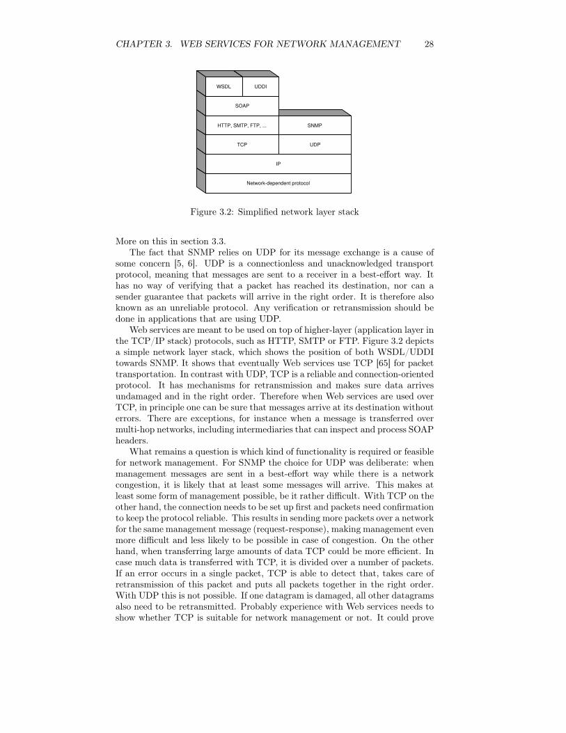
Figure 3.2: Simplified network layer stack
More on this in section 3.3.The fact that SNMP relies on UDP for its message exchange is a cause of
some concern [5, 6]. UDP is a connectionless and unacknowledged transportprotocol, meaning that messages are sent to a receiver in a best-effort way. Ithas no way of verifying that a packet has reached its destination, nor can asender guarantee that packets will arrive in the right order. It is therefore alsoknown as an unreliable protocol. Any verification or retransmission should bedone in applications that are using UDP.
Web services are meant to be used on top of higher-layer (application layer inthe TCP/IP stack) protocols, such as HTTP, SMTP or FTP. Figure 3.2 depictsa simple network layer stack, which shows the position of both WSDL/UDDItowards SNMP. It shows that eventually Web services use TCP [65] for packettransportation. In contrast with UDP, TCP is a reliable and connection-orientedprotocol. It has mechanisms for retransmission and makes sure data arrivesundamaged and in the right order. Therefore when Web services are used overTCP, in principle one can be sure that messages arrive at its destination withouterrors. There are exceptions, for instance when a message is transferred overmulti-hop networks, including intermediaries that can inspect and process SOAPheaders.
What remains a question is which kind of functionality is required or feasiblefor network management. For SNMP the choice for UDP was deliberate: whenmanagement messages are sent in a best-effort way while there is a networkcongestion, it is likely that at least some messages will arrive. This makes atleast some form of management possible, be it rather difficult. With TCP on theother hand, the connection needs to be set up first and packets need confirmationto keep the protocol reliable. This results in sending more packets over a networkfor the same management message (request-response), making management evenmore difficult and less likely to be possible in case of congestion. On the otherhand, when transferring large amounts of data TCP could be more efficient. Incase much data is transferred with TCP, it is divided over a number of packets.If an error occurs in a single packet, TCP is able to detect that, takes care ofretransmission of this packet and puts all packets together in the right order.With UDP this is not possible. If one datagram is damaged, all other datagramsalso need to be retransmitted. Probably experience with Web services needs toshow whether TCP is suitable for network management or not. It could prove
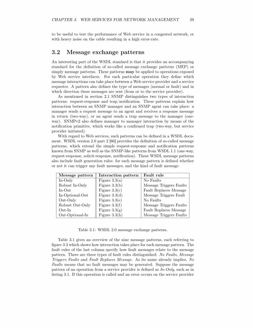
CHAPTER 3. WEB SERVICES FOR NETWORK MANAGEMENT 29
to be useful to test the performance of Web service in a congested network, orwith heavy noise on the cable resulting in a high error-rate.
3.2 Message exchange patterns
An interesting part of the WSDL standard is that it provides an accompanyingstandard for the definition of so-called message exchange patterns (MEP) orsimply message patterns. These patterns may be applied to operations exposedby Web service interfaces. For each particular operation they define whichmessage interactions can take place between a Web service provider and a servicerequester. A pattern also defines the type of messages (normal or fault) and inwhich direction these messages are sent (from or to the service provider).
As mentioned in section 2.1 SNMP distinguishes two types of interactionpatterns: request-response and trap/notification. These patterns explain howinteraction between an SNMP manager and an SNMP agent can take place: amanager sends a request message to an agent and receives a response messagein return (two-way), or an agent sends a trap message to the manager (one-way). SNMPv2 also defines manager to manager interaction by means of thenotification primitive, which works like a confirmed trap (two-way, but serviceprovider initiated).
With regard to Web services, such patterns can be defined in a WSDL docu-ment. WSDL version 2.0 part 2 [66] provides the definition of so-called messagepatterns, which extend the simple request-response and notification patternsknown from SNMP as well as the SNMP-like patterns from WSDL 1.1 (one-way,request-response, solicit-response, notification). These WSDL message patternsalso include fault generation rules: for each message pattern is defined whetheror not it can trigger any fault messages, and the kind of fault message.
Message pattern Interaction pattern Fault rule
In-Only Figure 3.3(a) No FaultsRobust In-Only Figure 3.3(b) Message Triggers FaultsIn-Out Figure 3.3(c) Fault Replaces MessageIn-Optional-Out Figure 3.3(d) Message Triggers FaultOut-Only Figure 3.3(e) No FaultsRobust Out-Only Figure 3.3(f) Message Triggers FaultsOut-In Figure 3.3(g) Fault Replaces MessageOut-Optional-In Figure 3.3(h) Message Triggers Faults
Table 3.1: WSDL 2.0 message exchange patterns.
Table 3.1 gives an overview of the nine message patterns, each referring tofigure 3.3 which shows how interaction takes place for each message pattern. Thefault rules of the last column specify how fault messages relate to the messagepattern. There are three types of fault rules distinguished: No Faults, MessageTriggers Faults and Fault Replaces Message. As its name already implies, NoFaults means that no fault messages may be generated. Suppose the messagepattern of an operation from a service provider is defined as In-Only, such as inlisting 3.1. If this operation is called and an error occurs on the service provider

CHAPTER 3. WEB SERVICES FOR NETWORK MANAGEMENT 30
Service
requester
Service
provider
1
(a) In-Only
Service requester
Service provider
1
(b) Robust In-Only
Service requester
Service provider
1
2
(c) In-Out
Service requester
Service provider
1
optional
(d) In-Optional-Out
Service
requester
Service
provider
1
(e) Out-Only
Service
requester
Service
provider
1
(f) Robust Out-Only
Service requester
Service provider
1
2
(g) Out-In
Service requester
Service provider
1
optional
(h) Out-Optional-In
Figure 3.3: WSDL message exchange patterns.

CHAPTER 3. WEB SERVICES FOR NETWORK MANAGEMENT 31
<interface name="fooInterface"><operation name="fooOperation" pattern="http://www.w3.org/2004/03/wsdl/in−only"><input message="fooInput"/>
</operation></interface>
Listing 3.1: MEP: In-Only
<interface name="fooInterface"><operation name="fooOperation" pattern="http://www.w3.org/2004/03/wsdl/robust−in−
only"><input message="fooInput"/><outfault messageLabel="fooOutFault"/>
</operation></interface>
Listing 3.2: MEP: Robust In-Only
side, the service requester should not be notified of this in a fault message.If delivering of fault messages is feasible, a Robust In-Only message patternshould be used, which has the fault rule Message Triggers Faults. This messagepattern is similar to In-Only with the difference being the ability to return afault message to the originator, as shown in listing 3.2.
The following definition for Message Triggers Faults is provided by theWSDL 2.0 specification [58]:
"For the pattern message-triggers-fault, the message that the faultrelates to identifies the message after which the indicated fault mayoccur, in the opposite direction of the referred to message. That is,the fault message will travel in the opposite direction of the messageit comes after in the pattern.".
It also provides the following definition of Fault Replaces Message:
"For the pattern fault-replaces-message, the message that thefault relates to identifies the message in place of which the de-clared fault message will occur. Thus, the fault message will travelin the same direction as the message it replaces in the pattern.".
An example of this last fault generation rule is the In-Out message pattern.Using this pattern, the normal way of interaction would be that upon receivinga message from the requester, the service provider would return a message toit. However, in case of an error at the provider side, the output message willnot be returned. Instead, a fault message is generated and replaces the normaloutput message. An example of this is shown in listing 3.3.
Message patterns that start with an initiating message from a service providerto a requester, are variants of what sometimes is also called the publish-subscribeparadigm. Service requesters subscribe to a certain service from a provider, en-abling this provider to send each requester a message whenever a certain eventhas occurred, like for instance when new information has become available [67].WSDL even allows for the requester to send response or fault messages back tothe service provider.
The above message patterns provides a greater variety of interaction patternscompared to SNMP . The request-response and trap interaction patterns from

CHAPTER 3. WEB SERVICES FOR NETWORK MANAGEMENT 32
<interface name="fooInterface"><operation name="fooOperation" pattern="http://www.w3.org/2004/03/wsdl/in−out"><input message="fooInput"/><output message="fooOutput"/><outfault messageLabel="fooOutFault"/>
</operation></interface>
Listing 3.3: MEP: In-Out
SNMP can best be compared with the message patterns In-Out and Out-Onlyfrom WSDL. In normal operation an SNMP manager sends a request to anSNMP agent and receives a response message. If an error has occurred on theagent with processing the request, this is send to the manager as response. Thisis an example of Fault Replaces Message and thus the In-Out pattern. Trapsare sent from an agent to a manager, which clearly corresponds to the Out-Onlypattern, since the manager can not be triggered to return a fault message to theagent.
3.3 Interface extensibility
In the following chapter issues with regard to standardisation of WSDL inter-faces, operations, messages, etc. for network management are being discussedin detail. This section will explain how WSDL interfaces can be extended withmore operations. This can prove to be very useful, for instance when certainWeb service operations have been standardised, but a vendor would like to pro-vide extra, proprietary management operations. Both NetConf and the WSMFprovide this functionality as well (see section 1.5).
Extensibility of an interface is the possibility for an interface to extend oneor more other interfaces. In that case an interface exposes all operations of theinterfaces it extends, along with any operations it defines. The only restrictionis that the extended interfaces themselves can not extend the interface that isused for extending, because that would create a loop. For example, interface Acan extend interface B, but then interface B is prohibited to extend interface A.
interface exposed operations
intf1 op1, ...intf2 op2, ...intf3 op1, op3, ...intf4 op1, op2, op4, ...
Table 3.2: Interface extension.
Interface extension can be achieved in WSDL by using the attribute extendsfor the <interface> element, with its value pointing to one or more otherinterfaces. To illustrate this mechanism, consider the interfaces intf1 and intf2that expose the operations op1 and op2 respectively from listing 3.4. Interfaceintf3 shows how interface intf3 is extended and thus exposes the operations op1and op3, as is also shown in table 3.2. Furthermore intf4 extends both intf1and intf2, thereby exposing the operations op1, op2 and op4.

CHAPTER 3. WEB SERVICES FOR NETWORK MANAGEMENT 33
<interface name="intf1"><operation name="op1" ... />...
</interface>
<interface name="intf2"><operation name="op2" ... />...
</interface>
<interface name="intf3" extends="intf1"><operation name="op3" ... />...
</interface>
<interface name="intf4" extends="intf1␣intf2"><operation name="op4" ... />...
</interface>
Listing 3.4: Interface extension
3.4 Additional Web service standards
Apart from SOAP and WSDL, which can be considered the basic standards,there are many additional efforts, proposals and standards that offer some spe-cific functionality, such as for transactions, security, reliability, etc. These effortstackle many common issues with regard to distributed systems, and thereforeinherently also for issues with network management. Since they are quite largein number and generally rapidly evolving, they will be mentioned briefly withreferences to the responsible company/standardisation body.
3.4.1 Security
Even though SNMP defines security provisions (in version 3), for certain reasonsthis is not always used [68]. One reason could be that security is self-containedand kept as independent as possible from other network services [7]. Somethingthat would make it much easier for developers is when existing security standardsand implementations can be reused, which is exactly that Web service-basedsecurity efforts attempt to accomplish.
WS-Security (version 1.0) [69, 70] and the Security Assertion Markup Lan-guage (SAML version 1.0) [71], both adopted by OASIS, are some of the im-portant efforts currently underway for securing Web services. In essence, WS-Security defines how to construct secure SOAP messages. One core definition ofWS-Security is about how to use XML-Signature [72] and XML-Encryption [73]with SOAP messaging. Another important definition is concerned with passingsecurity tokens in SOAP messages. This type of security is thus focussed atencryption of the communicated messages.
SAML is a markup language that gives a specification for exchanging autho-risation and authentication information. It includes bindings for WSDL/SOAPand could therefore be used in conjunction with Web services. It is very im-portant for Web services security to have it integrate well with existing keyand credential management infrastructure. A related standard is the XML KeyManagement Specification (XKMS) [74] which defines a protocol for distributingand registering public keys used in encrypting and decrypting messages.

CHAPTER 3. WEB SERVICES FOR NETWORK MANAGEMENT 34
Apart from Web services-related security measures, secure application pro-tocols such as HTTPS [75] and S/MIME [76] could also be used. These canmost certainly also be used for establishing secure connections to be used forSOAP message transport.
3.4.2 Transactions
Important initiatives that offer transactional functionalities are Web ServicesChoreography (WSCI version 1.0) [77], Business Process Execution Languagefor Web services (BPEL4WS version 1.0) [78] and the WS-Transaction Frame-work [79, 80, 81]. These initiatives are more or less overlapping, so it is just amatter of time to wait and see which kind of model will be implemented andused. A more extensive description and comparison of these initiatives can befound in an online article [82].
3.4.3 Reliability
In section 3.1 it was said that using TCP could make sure that SOAP messagesare delivered correctly, once and in the right order. However, it could be possiblethat the SOAP messages need to travel over different networks (for examplefrom internet onto the intranet) and thus several hops all using a differentapplication protocol. Consider the case that SOAP is transported over HTTPon one hop and SMTP on another. Sometimes it is feasible to still supportend-to-end reliable messaging, like in business operations such as the placementor cancellation of an order. These messages need to be reliably delivered andacknowledged [83]. To tackle this problem, WS-Reliability (version 1.0) [84]has been proposed by a number of companies and adopted by OASIS as WSReliable Messaging [85] for further development. WS-reliability defines extraSOAP headers to ensure reliable messaging.
3.4.4 Summary
The list of Web service additions seems almost ever growing. The most im-portant ones for network management have been discussed in this section, butmany more exist, like: WS-Inspection, WS-Routing, WS-Referral, Web Ser-vices Flow Language (WSFL) and the WS-Notification family of specifications(WS-BaseNotification, WS-BrokeredNotification, WS-Topics).
Web services are relatively new and its base standards (WSDL and SOAP)are still in their very early versions and constantly evolving. This holds evenmore for the additional "standards", most of which have just reached a version1.0 and only recently been handed over to a standardisation body like the W3Cor OASIS.
For completeness, an overview of the main Web service standards as well asseveral additional standards is provided in figure 3.4. It is an attempt to placethem in relation with SOAP and WSDL, as well as with each other.

CHAPTER 3. WEB SERVICES FOR NETWORK MANAGEMENT 35
S
E
C
U R
I
T
Y
M
A
N
A
G E
M
E
N
T
XML-SIG,
XML-
Encryption,
SAML,
XKMS,
WS-Security,
WS-License
COMMUNICATIONS HTTP, SMTP, FTP, ...
B a
s e T
e c h
n o
l o g
i e s : X
M L , S
c h e
m a
Descriptions WSDL
Messages
SOAP
SOAP Extensions WS-Reliability, WS-Routing, WS-Referral
B a
s e T
e c h
n o
l o g
i e s :
X M
L ,
S c
h e
m a
Extensions
Discovery UDDI, WS-
Inspection
Transactions BTP, BPEL4WS,
WS-Transaction
Process Flow WS-Choreography,
XLANG, WSFL
Figure 3.4: Web service related standards
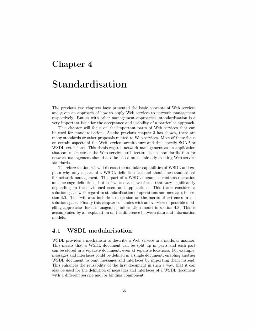
Chapter 4
Standardisation
The previous two chapters have presented the basic concepts of Web servicesand given an approach of how to apply Web services to network managementrespectively. But as with other management approaches, standardisation is avery important issue for the acceptance and usability of a particular approach.
This chapter will focus on the important parts of Web services that canbe used for standardisation. As the previous chapter 3 has shown, there aremany standards or other proposals related to Web services. Most of these focuson certain aspects of the Web services architecture and thus specify SOAP orWSDL extensions. This thesis regards network management as an applicationthat can make use of the Web services architecture, hence standardisation fornetwork management should also be based on the already existing Web servicestandards.
Therefore section 4.1 will discuss the modular capabilities of WSDL and ex-plain why only a part of a WSDL definition can and should be standardisedfor network management. This part of a WSDL document contains operationand message definitions, both of which can have forms that vary significantlydepending on the envisioned users and applications. This thesis considers asolution space with regard to standardisation of operations and messages in sec-tion 4.2. This will also include a discussion on the merits of extremes in thesolution space. Finally this chapter concludes with an overview of possible mod-elling approaches for a management information model in section 4.3. This isaccompanied by an explanation on the difference between data and informationmodels.
4.1 WSDL modularisation
WSDL provides a mechanism to describe a Web service in a modular manner.This means that a WSDL document can be split up in parts and each partcan be stored in a separate document, even at separate locations. For example,messages and interfaces could be defined in a single document, enabling anotherWSDL document to omit messages and interfaces by importing them instead.This enhances the reusability of the first document in such a way, that it canalso be used for the definition of messages and interfaces of a WSDL documentwith a different service and/or binding component.
36

CHAPTER 4. STANDARDISATION 37
<definitions><import location="http://example.com/wsdl/foo_interface.wsdl"/>
<binding>...</binding>
<service>...</service></definitions>
Listing 4.1: Import of interface WSDL
This functionality is achieved by the elements <import> and <include>.Both elements provide the same functionality of separating different componentsof a WSDL description, but <include> does this for components from the sametarget namespace, whereas <import> is used for different target namespaces[58]. Listing 4.1 gives an idea of how interfaces are imported from a separateWSDL document, having only the binding and service elements defined inthe main WSDL document.
The UDDI Technical Committee (see section 2.2.1) recommends a division ofWSDL documents into two separate WSDL definitions. One is the "service in-terface definition" part, which should contain the <types> (if any), <message>,<interface> and <binding> elements. The other WSDL definition is the "ser-vice implementation definition" part, which should contain the <service> ele-ment. Like the names suggest, it is an attempt to split up a WSDL definitionin an interface part and an implementation part.
The above recommendation is an attempt to provide a best practice in mod-ularising WSDL documents. However, it can be argued that bindings are betterdefined separate from the service interface definition. In principle, a bindingbounds an interface to a certain message protocol (SOAP). But for standard-isation it is more interesting to focus on the abstract definition, regardless ofany protocol. On the other hand, bindings could possibly also be standardisedseparately, thereby making operations available through a default protocol anddefining a standard encoding of the message parts. But it should not be part ofa standardised abstract interface definition. Figure 4.1 shows how a WSDL doc-ument is built up, when a modular approach is used. This shows how a WSDLdocument can be separated into an abstract part containing the messages andinterfaces (the what part), and two concrete parts: a binding (the how part)and a service (the where part).
For standardisation, the abstract part of a WSDL document is the mostimportant, since the operations and messages are defined here. When standar-dising the abstract part of a WSDL definition, the need for a modular approachis again stressed by the fact that standards should be defined independent fromeach other and for different purposes, whilst running on the same managementagent and offering a similar means of access. Much like SNMP, where for exam-ple the IF-MIB [86] and Host-resources MIB [87] are also defined by differentpersons, each standardising a disjoint set of management information, while allinformation from both MIBs can be accessed in a similar manner.

CHAPTER 4. STANDARDISATION 38
WSDL document
<binding name="foobar" type=”foo”>
<operation name=”get”>
<input>...</input>
<output>...</output>
...
</operation>
</binding>
<types />
<message name="getRequest">...</message>
<message name="getResponse">…</message>
<interface name="foo">
<operation name="get">
<input message="getRequest"/>
<output message="getResponse"/>
</operation>
</interface>
<service name="foobarService">
<endpoint name="foobarEndpoint"
binding="foobar">
...
</endpoint>
</service>
</definitions>
Import
Import
<definitions>
Figure 4.1: WSDL import mechanism
4.2 Management operations
The modularity of WSDL documents show how it is possible to define (andstandardise) operations, messages and types irrespective of binding and service.The question remains what form operations, messages and types should take inorder to provide feasible functionality. This section will provide an overview ofthe solution space.
4.2.1 Operation definition extremes
Now that is made clear how messages can be exchanged and what the corre-sponding interaction patterns are, it is time to have a closer look at the op-erations where these messages take part in. Messages and message exchangepatterns are merely a means of structuring the parameters that an operationexpects, their order and the possible fault messages. But it does not specify thefunctionality of an operation or what the result is after calling the operation.
Just as with SNMP, that uses a few generic operations, there needs to beagreement on which operations are to be supported for Web services. Of course,a very simple way is to translate SNMP operations directly to correspondingWeb service operations, but Web services can provide more flexibility withoutnecessarily increasing the complexity. Two extreme approaches are distinguishedin [7]. One approach has basic operations on WSDL level, such as get and set,with parameters passed as opaque types. This means that parameters are notdefined at WSDL level, although it is possible to specify them on a higher-level XML schema. Another approach is to define separate operations for eachmanaged object, such as getIfInOctets or changeIfoperationalStatus that bothprovide management functionality for a part of a network interface. These

CHAPTER 4. STANDARDISATION 39
operations only expect one parameter which is the index of the interface, todistinguish it from other interfaces in the same system.
This thesis states that in theory there are four different extreme approachesfor the definition of management operations. As the example above alreadymentions, there can be a difference in the granularity of operations: coarsegrained such as get and fine grained such as getIfInOctets. But for each form ofgranularity the parameters of operations can be either defined at WSDL level,or be kept opaque and possibly defined in a higher-level (XML) schema. Thiswill be referred to as operations that have either transparent or non-transparentparameters at WSDL level. These extreme forms are summarised in figure 4.2.
P a
r a m
e t e
r t r
a n
s p
a r e
n c y
Operation granularity
coarse fine
full
none
Get(param) GetIfInOctets(param)
Get(oid, index,
filter, ...)
GetIfInOctets(index,
filter, ...)
Figure 4.2: Operation extremes
4.2.2 Parameter transparency
The messages that are defined in a WSDL document and referred to from the op-eration definition can consist of several parts, each defined by a <part> element.The parts are used to actually comprise the parameters that an operation ex-pects. However each parameter does not necessarily need to be directly mappedto a message part. There are several ways to do this.
The extreme forms have already been mentioned: parameters can be definedat WSDL level or be completely transparent from it. An example of non-transparent parameters where each parameter is also mapped at a single messagepart is given in listing 4.2. In this case there is only one input parameter of thegetIfTable operation, but quite a number of output parameters.
On the other hand, parameters can also be combined and/or serialised insuch a way, that the parameters are not described at WSDL level anymore.Merely their serialisation is described in a message part. This is called param-eter transparency. In that case, serialising should be done upon composing amessage and de-serialisation upon receiving it. This means that besides aware-ness of the operation parameters, a management application (and agent) shouldalso offer (de-)serialisation capabilities. Listing 4.3 shows what the messages of
CHAPTER 4. STANDARDISATION 40
<message name="getIfTableRequest"><part name="community" type="xsd:string"/>
</message>
<message name="getIfTableResponse"><part name="ifIndex" type="xsd:unsignedInt" /><part name="ifDescr" type="xsd:string" /><part name="ifType" type="xsd:unsignedInt" /><part name="ifMtu" type="xsd:unsignedInt" /><part name="ifSpeed" type="xsd:unsignedInt" /><part name="ifPhysAddress" type="xsd:string" /><part name="ifAdminStatus" type="xsd:unsignedInt" /><part name="ifOperStatus" type="xsd:unsignedInt" /><part name="ifLastChange" type="xsd:unsignedInt" /><part name="ifInOctets" type="xsd:unsignedInt" /><part name="ifInUcastPkts" type="xsd:unsignedInt" /><part name="ifInDiscards" type="xsd:unsignedInt" /><part name="ifInErrors" type="xsd:unsignedInt" /><part name="ifInUnknownProtos" type="xsd:unsignedInt" /><part name="ifOutOctets" type="xsd:unsignedInt" /><part name="ifOutUcastPkts" type="xsd:unsignedInt" /><part name="ifOutErrors" type="xsd:unsignedInt" />
</message>
<interface><operation name="getIfTable" pattern="http://www.w3.org/2004/03/wsdl/in−out"><input message="getIfTableRequest"/><output message="getIfTableResponse"/>
</operation></interface>
Listing 4.2: Multiple message parts with simple types
<message name="getIfTableRequest"><part name="requestPart" type="xsd:string"/>
</message>
<message name="getIfTableResponse"><part name="responsePart" type="xsd:string"/>
</message>
Listing 4.3: Single message parts with opaque types
the getIfTable operation would look like when operation parameters are madetransparent at WSDL level.
An advantage of transparency is that management information is abstractedfrom protocol level, so the structure of information can change without havingto modify the operation messages. Suppose a Web service supports an operationwith full transparent parameters, such as in the bottom half of the graph of figure4.2, then all parameters are serialised into one message part (called param inthe example). In case the parameters are serialised in an XML structure, it canbe contained in a message where the part has (XML-)string type. On both themanager and agent side, a generic XML parser can then be used to extract theparameters from the message.
Parameter transparency is not the only way to abstract management infor-mation from protocol level. Note that Web services are much more flexible withregard to data-types. It is possible at WSDL-level to define complex types, thatalso comprise all parameters for an operation. But since they are not definedin a message definition but as a type, the structure of the type can still changewithout having to modify the message structure. Using the modularity of WSDL

CHAPTER 4. STANDARDISATION 41
<types><complexType name="ifEntry"><sequence><element name="ifIndex" type="xsd:unsignedInt"/><element name="ifDescr" type="xsd:string"/><element name="ifType" type="xsd:unsignedInt"/><element name="ifMtu" type="xsd:unsignedInt"/><element name="ifSpeed" type="xsd:unsignedInt"/><element name="ifPhysAddress" type="xsd:string"/><element name="ifAdminStatus" type="xsd:unsignedInt"/><element name="ifOperStatus" type="xsd:unsignedInt"/><element name="ifLastChange" type="xsd:unsignedInt"/><element name="ifInOctets" type="xsd:unsignedInt"/><element name="ifInUcastPkts" type="xsd:unsignedInt"/><element name="ifInDiscards" type="xsd:unsignedInt"/><element name="ifInErrors" type="xsd:unsignedInt"/><element name="ifInUnknownProtos" type="xsd:unsignedInt"/><element name="ifOutOctets" type="xsd:unsignedInt"/><element name="ifOutUcastPkts" type="xsd:unsignedInt"/><element name="ifOutErrors" type="xsd:unsignedInt"/>
</sequence></complexType>
</types>
<message name="getIfTableRequest"><part name="requestPart" type="xsd:string"/>
</message>
<message name="getIfTableResponse"><part name="responsePart" type="xsd:ifEntry"/>
</message>
Listing 4.4: Single message parts with complex types
documents, these types can even be defined in a different WSDL document orother XML schema definition and imported when needed.
Listing 4.4 shows how operation parameters are comprised in a single mes-sage part, but still known at WSDL-level. Note that this approach does resemblecomplete transparency with an XML structure defined at application level, justthe main difference is the explicit link between message part and part type. Inboth cases there is a need to define a higher-level XML schema. Examples ofXML schemas for SNMP management information can be found in [10, 88].
On the service requester side using a higher-level XML schema means thatthere should be functionality to firstly create such an XML data structure beforethe Web service can be called. Also it should have provisions to handle incomingmessages with complex XML data structures. This entails that it can only beused in either more specific network management applications or by more expe-rienced users/developers. In other words, parameter transparency offers a veryflexible and expressive use of operations, but this is only useful for professionalusers who need this kind of flexibility. For a PC user in his home environmentwho wants to include some management information in his spreadsheet, thiswill probably be too complicated. In that case, a simple operation is requiredwhere a user does not need to create complicated parameter structures in orderto compose the messages in a correct form.
Thus only if expressiveness is wanted and the use of (XML) parsers is ac-cepted, it is interesting to have operations with transparent parameters. Non-transparent parameters make operations easy to understand for users and easyto develop for developers.
For completeness it should be mentioned that it is also possible to have

CHAPTER 4. STANDARDISATION 42
<message name="getIfTableResponse"><part name="sizeTable" type="xsd:int"/><part name="responsePart" type="xsd:ifEntry"/>
</message>
Listing 4.5: Multiple message parts with simple and complex types
All
Interface (index = n)
Interface (index = 2)
System
SysLocation
SysUptime
Interface (index = 1)
IfInOctets
IfOutOctets
IfInErrors
IfIOutErrors
getAll()
getSystem()
getSysUptime()
getInterface( index )
getIfOutOctets( index )
Figure 4.3: Containment diagram
messages with combinations of the above mentioned approaches (they are meantto denote the extreme forms). As listing 4.5 shows, a message can have a partwith a simple type and a part with complex type at the same time. It caneven have a part with transparent and a part with non-transparent parameters,however the usability of such a message structure remains questionable.
4.2.3 Operation granularity
The other degree of freedom is operation granularity: the level of variationbetween very coarse and very fine operations. In order to illustrate this, we willassume to have a managed system of which system information and networkinterface information can be requested. The variables for system informationare rather straightforward, namely its location and uptime: SysLocation andSysUptime. The network interface information is a bit more complex, since asystem can have more than one interface. Therefore the same variables can beretrieved for each single network interface: IfInOctets, IfOutOctets, IfInErrorsand IfOutErrors. Figure 4.3 shows a containment diagram, which depicts theseseveral types of information we can retrieve from a system.
In order to retrieve this information from the system, we can define oper-ations that request the managed system for this information. If we considerusing very fine operations we would get operations such as getSysUptime or

CHAPTER 4. STANDARDISATION 43
getInterface( index ) getSystem()
getSysLocation()
getAll()
getSysUptime() getIfInOctets( index )
getIfOutOctets( index )
getIfInErrors( index )
getIfOutErrors( index )
Figure 4.4: Containment tree
getIfOutOctets as is also shown in figure 4.3. So a fine granularity of operationsmeans that for each variable a single operation is defined. Operations for net-work interface information need to have a parameter supplied to identify theinterface.
Suppose one wants to request all information from one network interface.This would result in calling an operation for each single variable. Therefore, abit coarser operations can also be defined, such as getSystem, getInterface(index)or perhaps even all information contained in the managed system. In that case,there is not only a single operation for each variable, but also for each containerwhere All is the container that contains ’everything’.
An advantage of this approach is that if the naming of the operations pre-cisely defines the functionality, it is very clear to a user which operation tocall to retrieve the information he wants. Generally speaking, the parameterspassed to an operation, be it transparent or not, can be simpler since selectingan object is already done by choosing the corresponding operation. In case ofmore than one instance of an object (such as the network interface example),an instance identifier (index) has to be provided.
Suppose someone wants to select different types of variables, such as allSystem variables and the IfInErrors of an interface with index = 2, then one isforced to call two separate operations. If we consider the containment hierarchyas a tree of fine operations (figure 4.4), then we can state that one fine operationdoes not allow selection in separate branches of the tree, e.g. one operation cannot retrieve both System and IfInErrors. Only the operation corresponding tothe node where these branches meet (getAll) would make it possible to retrievethis information. However, getAll does not only retrieve System and IfInErrors,but much more information that in this case would be redundant.
Suppose filtering the result would be possible on the agent side. This makes itpossible to get all information that satisfies some criteria, or get all informationwith some exceptions or up until a certain depth of the tree. We will use theterm filtering for any of these kinds of criteria. Theoretically filtering wouldmake it possible to retrieve any single variable or container only using getAlltogether with a filter. This leads to the concept of a very generic operation,for instance get. When provided with a container-name or variable-name, apossible index and perhaps a (simpler) filter, get can be used to retrieve anykind of information on any level in the containment tree. In that case, get is anexample of an extreme coarse operation, having a very generic name and usedfor more than a single task.

CHAPTER 4. STANDARDISATION 44
This behaviour would make get a very expressive operation, because withone single operation one can get any type of information from the managedsystem. It does make the parameters that should be passed to the operationmore complex, whether they are transparent or not. It also poses a more com-plex naming problem. With fine operations, the network manager only needs toknow which index to provide when it requests information from an object thatcan have more than one instance. On the other side, with coarse operations anetwork manager needs to know how to address any objects or instances on theagent side.
In an online MSDN article [89] there is a short discussion on granularityof interfaces of distributed systems in general. It states that a fine-grained in-terface is very likely to impede application performance, because it generallyrequires many method calls to achieve certain functionality, since each methodencapsulates just a very small piece of functionality. It further states that there-fore remote objects should define a coarse-grained interface that exposes only asmall set of methods. Each method should typically offer high-level functional-ity, like Place Order or Update Customer (compare with get or set operations)and all the data that a method needs should be passed as a parameter.
This view is also supported by the IONA [60] in a white paper on using MDAto develop Web services. It states that Web services should also provide coarse-grained operations that are compositions of more primitive functionality. Itenvisions that objects (in the object-oriented sense) defined on a service providershould not expose all their specific, fine-grained operations as a Web service,because they are not likely to provide the needed service to a service requester.It should rather provide operations that provide much more application logic,thereby most likely reducing network traffic since less interactions are neededcompared to fine-grained operations, to provide a similar level of functionality.
4.2.4 Summary
We have distinguished four extreme forms of management operations, all ofwhich have some advantages and disadvantages. Operation with non-transparentparameters are more likely to be used easily, since parameters are defined atWSDL level. When types are kept simple, it is very easy for a simple userin a home environment to include management information in for instance aspreadsheet or word processing document. The disadvantage of specifying man-agement information at WSDL level is that in case the management informationchanges, the WSDL also needs to be modified and possibly also managementapplications.
This in contrast to transparent parameters, where management informationis abstracted from protocol-level. This does pose the need for a higher-level(XML) schema for the definition of management information. The result is thateven though this approach seems more flexible and expressive, it is more likely tobe used by professional operators. It can be more complicated to create a higherlevel message structure in "simple", generic applications such as spreadsheets.
An advantage of having very coarse-grained operations is that the Web ser-vice definition can be kept rather simple, with regard to the number of availableoperations. The implementation of such an operation however, is likely to bemore complicated than fine-grained operation, same as for the structure of pa-rameters. Users of these operations also need to know less operations, although
CHAPTER 4. STANDARDISATION 45
they are possibly more complex. Fine operations can be easily understood, sinceit does not require extensive knowledge on an underlying data model (no needto provide parameters referring to variables, except indices). This could proveto be useful in generic applications. However, it also makes way for an ever-growing number of operations. With regard to this discussion it is interestingto see general statements on distributed systems/Web services, claiming thatcoarse-grained operations are the best solution for invoking remote operations.
The choice for a certain granularity will be a trade-off between simplicity andexpressiveness. However, with the extensibility of Web service interfaces it ispossible to have, for instance, both a standardised interface with coarse-grainedoperations, as well as a (proprietary) extended interface with fine-grained oper-ations.
4.3 Management information definition
4.3.1 Data models and information models
Management information in current standards is typically comprised in datamodels, such as SNMP MIBs and the DMTF CIM (see also section 1.5). Theusefulness of standardised data models is ensured by keeping the objects thatrepresent a particular resource the same at each managed system and by usinga common scheme for representation of management data to support interoper-ability.
But a distinction can be made between data and information models. InRFC3444 [90] is explained how models can be described at different abstractionlevels. An information model (IM) is defined on a higher abstraction level thana data model (DM). An IM can be considered to have easier to grasp conceptsbehind it, since it should hide all protocol and implementation details. A formaldefinition of an IM can be found in RFC 3198 [91]:
"An abstraction and representation of the entities in a managed en-vironment, their properties, attributes and operations, and the waythat they relate to each other. It is independent of any specific repos-itory, software usage, protocol, or platform.".
The same RFC gives the following definition for a DM:
"A mapping of the contents of an information model into a form thatis specific to a particular type of data store or repository. A "datamodel" is basically the rendering of an information model accordingto a specific set of mechanisms for representing, organising, storingand handling data.".
In other words, a DM is an "implementation" of an IM. The availability of anumber of different implementation platforms entails that a single IM can resultin several DMs. Suppose a general management IM exists, one can state thatboth the SNMP MIBs defined in SMI, and the DMTF CIM defined in ManagedObject Format (MOF) (not to be confused with the MOF as is known fromMDA: the Meta-Object Facility) are the DMs. This is depicted in figure 4.5.
However, to date merely the DMs of management information exist. Thesemodels generally contain lots of details and are therefore not always easily un-derstood. The CIM has an accompanying set of non-normative UML class

CHAPTER 4. STANDARDISATION 46
Management
information model
SNMP MIB
(SMI)
CIM schema
(MOF) ...
IM
DM
Figure 4.5: Management IM and DMs
diagrams based on the MOF definitions, but they do not contain all aspectssince some of that is not possible to model in UML.
Based on this observation, as well as remembering the typical usage of MDAtechniques, it can be of interest to define an abstraction of the existing man-agement DMs, thereby creating a management IM (or a platform independentmodel, in MDA terminology). Theoretically one could define a transformationthat could map this IM to MIBs or CIM schema definitions and thus creating aplatform specific model. This management IM could be defined in a variety oflanguages, like UML class diagrams or Entity-Relationship (ER) diagrams. Ofcourse, natural (English) language is also an option, however this is not usefulfor MDA and can hardly be used for (automatic) model transformation.
RFC 3444 mentions that UML has an advantage above other modellingtechniques, especially because it is being widely adopted in the industry andtaught in universities. Also, UML is standardised (by the OMG) and many toolsfor editing UML diagrams are now available. And even though MDA does notimpose the use of UML, current MDA tools (like ArcStyler and Objecteering)are commonly based on UML modelling.
Furthermore RFC 3444 finds it advisable that in general object-orientedtechniques should be used to describe an IM. Important advantages of object-oriented techniques are the notions of abstraction and encapsulation, as well asthe possibility of object definitions to include operations. So even though ERdiagrams could be very useful to describe management information and relation-ships in a more abstract level, they do lack these object-oriented characteristics.
4.3.2 Management information models
As mentioned before, an IM can be defined in a variety of modelling techniques.But different modelling techniques impose different kinds of models, in whichmanagement information can be defined in different ways. This section makes adistinction between various types of models, namely data-oriented, task-orientedand object-oriented. These are based on [92], where a similar distinction is madebetween approaches for network management protocols. Although, instead ofthe terms data-oriented and task-oriented, it uses the terms variable-orientedand command-oriented respectively.
A data-oriented model focuses mainly on management information itself,where each piece of information is comprised in a variable (hence variable-oriented in [92]). Generally, such a model does not contain operations. Forexample, ER diagrams can be considered data-oriented by nature, since it fo-cusses on the data modelling and the relationships between related groups of

CHAPTER 4. STANDARDISATION 47
data (entities). It is not possible to model operations in this type of diagram.An example of a data-oriented DM is a MIB defined in SMI.
IMs can also be task-oriented. This kind of model defines tasks that typicallyhave well-defined semantics. Examples of commands are: reset, reboot or closeall connections. In other words, management functionality is divided in a num-ber of tasks that can be performed on the managed system. Natural language(English) is very suitable for describing task-oriented models. An example ofa DM that could be considered task-oriented is WSDL, which abstracts fromunderlying data structures by only defining operations.
Finally object-oriented models can be distinguished. They can be seen asa combination of variable-oriented and command-oriented models, since theydefine objects that can expose both attributes (variables) and operations. Amanager then invokes operations on these objects and receives notifications withthe result. UML diagrams are highly suitable for modelling an object-orientedmanagement IM. CIM can be regarded as an example of an object-orientedmanagement DM, even though they are probably closer to IMs than for instancethe SMI MIB DMs [90].
The following two sections will focus on data-oriented ER diagrams andobject-oriented UML class diagrams and discuss their suitability for modellingan IM. Task-oriented models will not be discussed here, because of the preas-sumption that they should be modelled in natural language. This is not verysuitable for usage in an MDA tool, although it could be a topic for furtherresearch.
4.3.3 Data-oriented information model
Database analogy
Before explaining how ER diagrams can be used to define a data-oriented IM,firstly it is interesting to recognise the analogy of MIBs with databases. Man-agement information defined in MIBs is data-oriented by nature. In [1] we canfind the following description of a MIB: "In essence a Management Informa-tion Base is a database structure in the form of a tree". Such a descriptionof a MIB makes an analogy with traditional Database Management Systems(DBMS) valid. In fact, the SNMP architecture and data definition can easily becompared with a so-called multi-database system (MDBS) architecture. In [93,p.87] a classification schema of distributed databases is given, with variationsalong three axes: the autonomy of local systems, their distribution and theirheterogeneity. An MDBS is a homogenous collection of autonomous databaseswithout distribution.
We consider the analogy of a local DBMS that is part of a distributeddatabase with an SNMP agent that is part of a network management system.Suppose an SNMP agent is regarded as a DBMS containing management infor-mation of that particular device, then all agents in a certain network in principlehave the same DBMS, each having identical functionality and interface. This isan example of homogeneity. Agents can be regarded as being autonomous, sinceeach agent does not know the presence of other agents, nor the concept of coop-eration with them. Finally, management information is not really distributed.Each agent has, in principle, the same database structure, but containing itsown information. The architecture is not meant to be distributed and transpar-

CHAPTER 4. STANDARDISATION 48
ent to a manager anyway, since the location of information plays a vital role innetwork management.
A network manager in its turn can then be compared to some sort of globaldatabase manager that has control over each individual DBMS. In DBMSs itis also common to have a few generic operations, that can be used to queryany database. The most commonly used query language for databases is theStructured Query Language (SQL) and even though it is standardised by bothANSI and ISO [94], many variations exist across implementations of differentvendors. The SQL standard offers four basic operations that together form theSQL data-manipulation language (DML) [95, p.1]:
• SELECT - retrieves data from a database by providing a description of thedesired result set
• UPDATE - modifies existing data in a database table, but does not removeit
• INSERT INTO - inserts a new row in a database table
• DELETE - removes rows from a database table
SQL offers much more functionality than will be discussed here, such ascreation/deletion of databases and tables, indexing, definition of views, trans-actions, locking and access control. The focus here will be on the data definitionand relations. SQL is a set-based programming language that allows for the ma-nipulation of data stored in two-dimensional tables, also referred to as a relation.The name of a particular relation and the corresponding set of attributes is calleda schema. Suppose a relation named Interface has the following schema:
Interface( Description, Speed, PhysicalAddress )
then Interface is the name of the relation and Description, Speed and Physical-Address are its attributes. The attributes depict the structure of the table, thusa valid row in this table would be:
( eth0, 100, 0:0:b4:a9:1:5a )
A row in a table is formally called a tuple and its attributes are called com-ponents of a tuple. The relational database model requires each component tobe of some sort of atomic type, i.e. they can’t be tables, sets, arrays or otherstructures.
Description Speed PhysicalAddress
eth0 100 0:0:b4:a9:1:5aeth1 100 0:5:c6:c1:4d:6ceth2 10 0:5:8d:8:7a:4b
Table 4.1: Interfaces relation.
The operations from the SQL DML are set- or tuple-based and are designedto retrieve, modify, insert or delete one or more tuples from a table. SELECT
and UPDATE can also work on components of a tuple. For example, consider

CHAPTER 4. STANDARDISATION 49
Description Speed PhysicalAddress
eth0 100 0:0:b4:a9:1:5aeth1 100 0:5:c6:c1:4d:6ceth2 10 0:5:8d:8:7a:4b
Table 4.2: Query: SELECT * FROM Interfaces.
Description
eth0eth1eth2
Table 4.3: Query: SELECT Description FROM Interfaces.
the table of 4.1 then tables 4.2, 4.3 and 4.4 give the result sets of three simpleSELECT queries. It shows a little how powerful SQL queries can be.
With SQL much more powerful queries are possible by joining relationships,creating unions or intersections of result sets, etc. This shows that SQL is alanguage that can be used and understood very easily, like the simple examplesin this section show, but also be used in a very powerful way by creating verycomplex queries. SQL has proven itself to be a language understood and usedby many people, varying from simple home users to very professional users, andyet it only offers very few operations to the user.
A feature of databases is also that they can contain triggers. A trigger is anaction that can take place after a certain defined event has occurred. Usuallythis happens after a table has been accessed in a certain way. When an eventoccurs, some operation can be performed, which is defined in a database specificprogramming language. One can think once again of the analogy with networkmanagement and more specific: SNMP traps. A trap can be compared with adatabase trigger, albeit that they usually do not take place after data access,but after some error has occurred at the agent side.
Entity-Relationship diagram
Databases can be modelled in various ways. There is not a single definitionlanguage. Some use natural language, others a formal language or even graphicaltools, but all focus on data relationships. A very common modelling techniquefor databases is the Entity-Relationship diagram. This diagram can be used fordescribing the tables in a database and the relationships between them. Thiskind of diagram abstracts from any database specific definitions, and thus adatabase model can be regarded as an IM.
Description Speed PhysicalAddress
eth2 10 0:5:8d:8:7a:4b
Table 4.4: Query: SELECT * FROM Interfaces WHERE Speed=10.

CHAPTER 4. STANDARDISATION 50
system
sysDescr
sysObjectID sysUpTime
sysContact
sysName
sysLocation
sysServices
sysORLastChange
Figure 4.6: System information ER diagram
Recalling the analogy of DBMS’s with network management, we can regarda MIB as database model for a particular kind of data. The difference is thatin MIBs data is not only comprised in a table, but also as scalars that appearnot to have any relationship with other scalars. However, MIBs are collectionsof related managed objects, i.e. there appears to be some sort of conceptualrelationship after all. One way this can be explained, is by describing thesystem information defined in the SNMPv2-MIB. It consists of the followingscalars: sysDescr, sysObjectID, sysUpTime, sysContact, sysName, sysLocation,sysServices and sysORLastChange as well as a table called sysOrTable.
Figure 4.6 could be a possible ER diagram to comprise this kind of infor-mation. It has the scalars with system information contained in a table calledsystem. Of course it is clear that this is not a real table, since it may onlycontain one single row.
This can have a large influence on the naming of objects, or cells. MIBs(and thus SNMP) rely heavily on object identifiers and their ordering in theSNMP naming tree. But database-style models are very much focussed ondata and relationships, resulting in a more expressive, but not necessarily morecomplicated (as the widespread usage of SQL shows) way of accessing data.
Another advantage of focussing more on relationships is that modelling re-dundant data can easily be avoided. For example, consider parts of the IF-MIBand the Host-Resources MIB. The first defines information on network inter-faces and the latter on the software and hardware running on host computersconnected to the internet directly used by human beings. The Host-ResourcesMIB therefore also contains a table with network interfaces available on thehost. The only column in this table contains indexes which should correspondto the indexes in the network interface table from the IF-MIB. The way thisrelationship is modelled in the Host-Resources MIB definition [87] is by naturallanguage. In an ER diagram, this can be explicitly modelled by using primaryand foreign keys, as figure 4.7 shows. A primary key in a table should uniquelyidentify each table entry, whereas a foreign key points to a primary key in adifferent table.
For instance, the hrDeviceTable can contain devices that are network inter-faces. Specific information for network interfaces is contained in the hrNetwork-Table table. Each device has a unique index, also called primary key, namelyhrDeviceIndex. This is used as a primary key in both the hrDeviceTable and

CHAPTER 4. STANDARDISATION 51
IfTable
PK ifIndex
ifDescr
ifType
ifMtu
ifSpeed
ifPhysAddress
ifAdminStatus ifOperStatus
ifLastChange
ifInOctets
ifInUcastPkts
ifInDiscards
ifInErrors
ifInUnknownProtos
ifOutOctets
ifOutUcastPkts
ifOutErrors
hrNetworkTable
PK,FK1 hrDeviceIndex
FK2 hrNetworkIfIndex
hrDeviceTable
PK hrDeviceIndex
hrDeviceType
hrDeviceDescr
hrDeviceID
hrDeviceStatus
hrDeviceErrors
Figure 4.7: IfTable ER diagram
the hrNetworkTable. Moreover, the hrDeviceIndex should be the same in bothtables, which is ensured by defining hrDeviceIndex as a foreign key of the hr-NetworkTable as well. Anytime an entry is added in the hrNetworkTable, thedatabase should check if the index already exists in the hrDeviceTable. TheHost-Resources MIB defines by natural language that each entry in the hrNet-workTable should also be contained in the IfTable. This is ensured by defininganother foreign key that relates the hrNetworkIfIndex to the IfIndex of theIfTable.
In fact, modelling in such a way makes immediately clear that there is aredundant table, namely the hrNetworkTable. This table has a one-to-one rela-tion with the IfTable and better design practice would be to have the IfTablecontain a field called hrDeviceIndex, which functions as a foreign key to thehrDeviceTable.
4.3.4 Object-oriented information model
Modelling IMs can also be done using an object-oriented approach. This sectionwill regard a managed object in the traditional object-oriented sense. Thismeans that a managed object represents a "tangible" entity, that is part of amanaged system. Examples of "tangible" entities are: CPU, network interface,hard disk, but also running software, TCP protocol, SNMP protocol, etc. Eachobject has an interface that abstracts from its internal structure by providingoperations to other objects. Attributes of an object can not directly be retrieved,this needs to be done by accessor operations. For a more elaborate and detaileddescription of object-oriented design, the reader is referred to [96].
There has been an attempt to comprise SNMP management informationin an IM, based on UML class diagrams [97]. In [98] a heuristic algorithmis presented to automatically translate MIB modules to UML class diagrams.However this algorithm has a number of limitations, because it depends onmany "unwritten" rules for writing MIB modules, varying from the naming of

CHAPTER 4. STANDARDISATION 52
managed objects to the introduction of new data types. The algorithm expectsrelated objects to have a similar prefix in their names, but this is not mandatoryin SMI. Also it is said that good MIB authors should define their own data types,which the algorithm can then use to recognise references between tables. Thisalgorithm is an integrated part of the smidump program which is part of thelibsmi SMI compiler package [99].
Chapter 5 explains in more detail how object-oriented IMs can be used toderive Web services (or rather a framework that needs more implementation)by making use of an MDA tool.
4.3.5 Summary
A distinction between a data-oriented, a task-oriented and an object oriented IMfor the definition of management information. A data-oriented IM can typicallybe modelled as an ER diagram, a task-oriented IM in natural language andon object-oriented IM in UML. Since both data-oriented and object-orientedIMs can be modelled in a rather formal modelling language, it is interesting toinvestigate these for use with MDA tools.
Since the concepts are rather similar, ER diagrams can be relatively easilyderived from SNMP MIBs, but this is only based on the examples given. Thisis an issue for further research.
An attempt has been made to reverse engineer MIBs to object-oriented UMLclass diagrams, but still a lot needs to be done by hand. An advantage ofthis approach is that current MDA tools (like Objecteering and ArcStyler) arecommonly UML based. UML is much more elaborate than ER diagrams, alreadybecause it is able to model behaviour.

Chapter 5
Case study: host-resources
In this chapter the theory and ideas from the previous chapters shall be appliedto create a Web service using an MDA tool. The tool of choice is ArcStyler(version 4.0.108) [100], since it provides good documentation in order to quicklyand easily get to know the tool and make use of it.
The Web service that will be created will be based on the managementinformation stored in the Host-resources MIB. This can be regarded as a MIBwith easy to grasp concepts behind it, plus it contains both single variablesand conceptual tables. Firstly the purpose of the Host-resources MIB shall beexplained in section 5.1. After this, a Web service will be created based on adata-oriented approach (explained in terms of an EM diagram) in section 5.2.This will be a Web service that resembles SNMPv2 functionality, to explain howSNMP resembles Web services and to explain how coarse-grained operationswill have its influence on the WSDL definition. Finally, section 5.3 presentshow an object-oriented information model could be generated from the MIBdefinition and how this information can be accessed through many very fine-grained operations.
5.1 Host-Resources MIB
Before creating a Web service based on the Host-Resources MIB, the purpose ofthis MIB module shall firstly be explained. The Host-Resources MIB specifieswhich information is managed on a host. A host is defined as [87]:
"The term "host" is construed to mean any computer that communi-cates with other similar computers attached to the internet and thatis directly used by one or more human beings.".
Generally, a host is a computer connected to the internet and used by one ormore persons. It can be argued how a general definition of a host can lead to aformal specification, therefore some descriptions shall be given firstly.
A general idea of a host is a computer system consisting of a CPU, (logical)disk and a network interface (since the definition requires it to be connectedto the internet). Many systems will also have devices such as printers, soundcards, cd-rom drives and keyboards attached. A host also has one or moreoperating systems installed and software running on it. It is clear that this list
53

CHAPTER 5. CASE STUDY: HOST-RESOURCES 54
is not exhaustive, since new devices and software are developed all the time.Furthermore, a host can change its configuration over time. Despite these facts,there is a core set of items that are consistent across all systems, even if theyare given different names. The components in this core set can be classified intwo categories:
• a hardware device
• a software package (such as a program or a collection of programs)
As mentioned before, the list of hardware devices is open-ended. Every distinctpiece of hardware on a host is a device. At least 3 characteristics are mentionedby [101] which are common to all devices, regardless of their function:
• an indication of the manufacturer and product model
• a current status
• the number of errors that the device has reported
Of course more specific information can be managed for a certain device, butthis highly depends on the type of device. A short and simple idea of this morespecific information is given in the following list:
• processors: processor load, firmware version
• printers: status (such as: printing, idle or error has occurred), detectederror, paper left
• disks: media access (RO or RW), type (such as: floppy, HD, cd-rom),capacity, partitions, file-systems, the partitions that comprise a given filesystem
There are 3 general categories of software packages [101]:
• operating system
• device driver
• user application
This clear distinction between software categories has been made for manage-ment purposes. For any program it is useful to know where it is installed, ifit is running and what its status is (for instance waiting for an event or re-source). It could also be useful to know how many system resources a programis consuming.
5.2 Data-oriented approach
Now that the purpose of the Host-Resources MIB is clear, a Web service will beconstructed following the data-oriented approach. This part of the case studywill be based on the operations defined in the SNMPv2 protocol. This is to showhow SNMP and Web service could offer very similar functionality, but also togive an idea of a situation with coarse-grained operations.

CHAPTER 5. CASE STUDY: HOST-RESOURCES 55
5.2.1 Information model
In section 4.3 a data-oriented approach for the definition of an informationmodel of management information was discussed. An analogy with databaseswas recognised and it was shown that it was relatively easy to define an ERdiagram with management information.
However, for the sake of simplicity a new naming scheme for objects in anER diagram will not be given here. Instead, the naming as defined in theHost-resources MIB will be used, to simplify the explanation of coarse-grainedoperations based on SNMP. In other words, this example will be using SNMP’sdata model instead of an information model. Another reason is that ArcStyleris based on the use of UML diagrams and therefore it can not use ER diagramsfor automatic model transformation. This could be an interesting topic to in-vestigate in the future though. But most probably model transformation thenneeds to be done manually.
It is nevertheless worth mentioning how the Host-resources MIB could bemapped to an ER diagram and thus this is included in appendix B.
5.2.2 Protocol
Management operations
Section 2.1.4 explains the operations that are used in SNMPv2 and depicts thecorresponding message structures. These operations are: Get, Get-next, Get-Bulk, Set, Inform, SNMPv2-Trap. This section will give a simple translation ofthese operations to WSDL definitions.
These operations together with their corresponding sequence diagrams, leadto the design of WSDL operations as shown in listing 5.1.
The PDU type and the request-id fields are omitted, since they have nomeaning on WSDL level. The "PDU type" of a WSDL message is in factcomprised in the operation name. And the request-id is not useful since amechanism to differentiate which response belongs to which request is alreadyavailable.
Message structure
Section 2.1.4 also explained the PDU formats that are used for a certain opera-tion. These PDU formats can directly be related to WSDL message descriptions.This example does not attempt to provide the most accurate transformation ofthe SNMP PDUs to WSDL messages possible, but it should give a clear idea ofhow SNMP functionality can be achieved in WSDL.
It makes use of several types that are defined in an XML Schema-basedstructure. The complete type definition can be found in appendix E. Thisexample makes use of non-transparent parameters, but with several messageparts that have a type defined in an external schema. Of course, these typescould just as well be defined in the WSDL definition, but it is kept separate forreadability.
Recall from SNMP that the variable-binding part of a PDU, is a list of name-value parts. However, the length of the list (i.e. the number of pairs) is notknown at definition time. Therefore it needs to be defined recursively. In SMIthis is done by defining a VarBindList type, such as in listing 5.3 and in WSDL

CHAPTER 5. CASE STUDY: HOST-RESOURCES 56
<operation name="get"><input message="tns:requestMessage"/><output message="tns:responseMessage"/><fault message="tns:errorMessage" name="error−status"/>
</operation>
<operation name="get−next"><input message="tns:requestMessage"/><output message="tns:responseMessage"/><fault message="tns:errorMessage" name="error−status"/>
</operation>
<operation name="set"><input message="tns:requestMessage"/><output message="tns:responseMessage"/><fault message="tns:errorMessage" name="error−status"/>
</operation>
<operation name="get−bulk" parameterOrder="non−repeaters␣max−repetitions␣variable−binding">
<input message="tns:get−bulkRequest"/><output message="tns:responseMessage"/><fault message="tns:errorMessage" name="error−status"/>
</operation>
<operation name="trap"><output message="tns:trapMessage"/>
</operation>
<operation name="inform"><input message="tns:trapMessage"/><output message="tns:responseMessage"/><fault message="tns:errorMessage" name="error−status"/>
</operation>
Listing 5.1: SNMPv2-style operations
<message name="requestMessage"><part name="variable−binding" type="xsd1:VarBindList"/>
</message>
<message name="responseMessage"><part name="variable−binding" type="xsd1:VarBindList"/>
</message>
<message name="get−bulkRequest"><part name="non−repeaters" type="xsd:int"/><part name="max−repetitions" type="xsd:int"/><part name="variable−binding" type="xsd1:VarBindList"/>
</message>
<message name="trapMessage"><part name="sysUpTime" type="xsd1:ObjectName"/><part name="snmpTrapOID" type="xsd1:ObjectName"/><part name="variable−binding" type="xsd1:VarBindList"/>
</message>
<message name="errorMessage"><part name="error−status" type="xsd1:error−status"/>
</message>
Listing 5.2: SNMPv2-style messages

CHAPTER 5. CASE STUDY: HOST-RESOURCES 57
−− variable binding
VarBind ::= SEQUENCE {name ObjectName,
CHOICE {value ObjectSyntax,unSpecified NULL, −− in retrieval requests
−− exceptions in responsesnoSuchObject [0] IMPLICIT NULL,noSuchInstance [1] IMPLICIT NULL,endOfMibView [2] IMPLICIT NULL
}}
−− variable−binding list
VarBindList ::= SEQUENCE (SIZE (0..max−bindings)) OF VarBind
Listing 5.3: VarBindList type definition (SMI)
this should be done in a very similar way: defining a VarBindList type. TheXML Schema definition for this type is listed in 5.4. The similarities betweenthese two definitions are rather clear: in SMI the VarBindList type is a sequenceof Varbind types with minimum number of occurrences is 0 and the maximumnumber of occurrences is max-bindings. In XML Schema this is the same, onlywith the maximum number of Varbind occurrences unbounded. The completeXML Schema for SNMP-based types can be found in appendix E.
5.2.3 Summary
SNMP can be modelled as a Web service as well. In that case it is possibleto use SNMP-like operations and addressing, while at the same time one canmake use of the provisions that Web services (will) offer, such as security andtransactions.
The abstract interface definition as discussed in this section is not meant tobe an accurate specification of SNMP functionality in WSDL. Especially withregard to data types, there is a lot to improve since mostly generic XML Schemastring types are used. The complete WSDL abstract interface definition for asimple SNMP-like Web service is listed in appendix C. For completeness, abinding definition is also provided for this Web service in appendix D. This isonce again an example of WSDL modularity: the binding definition imports theabstract interface definition. The abstract interface definition in its turn usesthe XML Schema import mechanism to import special data types that need tobe used for this particular Web service.
5.3 Object-oriented approach
This section will describe how a network management Web service can be de-veloped using an object-oriented approach. Where the data-oriented approachfocussed on coarse-grained (SNMP-based) operations to access them, this ap-proach will focus on deriving an object-oriented information model (UML classdiagram) from the MIB definition and defining fine-grained operations. Consid-

CHAPTER 5. CASE STUDY: HOST-RESOURCES 58
<xsd:complexType name="VarBindList"><xsd:sequence>
<xsd:element maxOccurs="unbounded" minOccurs="0" name="varbind" type="xsd1:VarBind"/>
</xsd:sequence></xsd:complexType>
<xsd:complexType name="VarBind"><xsd:sequence>
<xsd:element maxOccurs="1" minOccurs="1" name="name" type="xsd1:ObjectName"/>
<xsd:choice><xsd:element name="value" type="xsd:string"/><xsd:element name="unspecified" type="xsd:string"/><xsd:element name="noSuchObject" type="xsd:string"/><xsd:element name="noSuchInstance" type="xsd:string"/><xsd:element name="endOfMibView" type="xsd:string"/>
</xsd:choice></xsd:sequence>
</xsd:complexType>
<xsd:simpleType name="ObjectName"><xsd:restriction base="xsd:string"/>
</xsd:simpleType>
Listing 5.4: VarBindList type definition (XML Schema)
ering that management information as defined in the Host-resources MIB shallbe modelled, it is logical to use the smidump program which is described insection 4.3.4 as it provides an algorithm for reverse engineering MIB modulesto UML diagrams.
5.3.1 Information model
The first step is to let smidump convert the Host-resources MIB module defini-tion to a UML class diagram. The generated diagram is stored in the internalformat of DIA, which is an open source UML editor [102]. This editor can thenbe used to display the result, which is included in appendix F.
Because of the limitations of smidump the generated model is not completelycorrect. Certain relationships have been generated that do not exist, most prob-ably because of some confusion with indexes. Also a hrStorage class has beengenerated with only one attribute hrMemorySize that could easily be combinedwith the hrSystem class. The hrMemorySize variable contains "the amount ofphysical read-write main memory, typically RAM, contained by the host" andcan also be seen as an attribute of the system. This simplifies the model byreducing it with one class.
Summarising, some modifications on the generated model had to be mademanually, resulting in a revised UML class diagram. A simplified diagram isdepicted in figure 5.1 that shows a few less relations between objects than thegenerated diagram. The full diagram (including attributes) is presented in ap-pendix G.

CHAPTER 5. CASE STUDY: HOST-RESOURCES 59
hrDiskStorageEntry
hrSWInstalledEntry
hrSWRunPerfEntry
hrProcessorEntry
hrPartitionEntry
hrNetworkEntry
hrStorageEntry
hrSWRunEntry
hrPrinterEntry
hrDeviceEntry
hrSystem
hrFSEntry
sparse augments1
sparse augments
sparse augments2
sparse augments3
exists on
<<association>>
1
<<association>>
0..*
Figure 5.1: Simplified Host-resources UML class diagram
5.3.2 Protocol
Management operations
The revised UML class diagram forms the basis for creating the managementWeb service. This shall be done with ArcStyler that can use the UML classdiagram to generate the Web service. ArcStyler contains a built-in UML editor,thus the DIA UML class diagram is easily inserted in ArcStyler. In fact, figure5.1 is the UML diagram drawn in ArcStyler.
The next step is the modelling of the Web service operations, which shouldshow what a situation with very fine-grained operations looks like. Similarto the approach that has been adopted in [32], where operations are definedat protocol- and object-level, this example will have operations that can beregarded to be at object-level. For each attribute of each class an accessor willbe created. Each attribute will have at least a read operation, though sometimesit may also have a write operation. The choice for having read-only or read-writeattributes are made depending on the way this is defined in the Host-resourcesMIB. This form of accessibility is unfortunately not depicted in the generatedclass diagram.
Unlike MIBs, where each value has a certain fixed number assigned to it,objects in a UML class diagram pose a naming problem: some objects can haveonly one instance (like hrSystem) and some can have more than one (hrDevic-eTable). This distinction is typically made for objects that are derived fromtable entries (each entry can represent an object instance) and for objects thatare derived from (combinations of) related variables not part of a table. Anobject that can have only one instance is called singular. Given the fact that an

CHAPTER 5. CASE STUDY: HOST-RESOURCES 60
+getHrDeviceStatus()
+getHrDeviceErrors()+getHrDeviceDescr()
+getHrDeviceIndex()
+getHrDeviceType()
+getHrDeviceID()
hrDeviceEntry
+hrDeviceStatus : string
+hrDeviceDescr : string+hrDeviceErrors : long
+hrDeviceType : string
+hrDeviceID : string+hrDeviceIndex : int
(a) Non-indexed operations
+getHrDeviceStatus( index )
+getHrDeviceErrors( index )+getHrDeviceDescr( index )
+getHrDeviceType( index )
+getHrDeviceID( index )
hrDeviceEntry
+hrDeviceStatus : string
+hrDeviceDescr : string+hrDeviceErrors : long
+hrDeviceType : string
+hrDeviceID : string+hrDeviceIndex : int
(b) Indexed operations
Figure 5.2: hrDeviceEntry class definition.
object is called remotely, the Web service should provide a way of referring toa particular instance of that object, followed by invoking an operation on thatinstance.
In principle Web services provide ways of accessing operations from objects,but not from particular instances. In other words, by exposing only operationsfrom objects, a Web service can normally not differentiate between instances.Therefore an instance reference should be provided when invoking a Web serviceoperation, so the Web service can invoke that same operation on the referencedinstance. Recall from MIBs that table entries are all identified by a certainindex, thus objects that can have multiple instances, will have this index as anattribute. This index will thus be different for each instance and can thereforebe used to differentiate between them. This index should be provided whencalling an operation through a Web service.
For example, the hrDeviceEntry object (figure 5.2(a)) can have multiple in-stances. Each attribute is read-only according to the MIB definition, thereforeonly get-operations are defined for each attribute. For any normal object thiswould suffice, but since all operations are exposed as Web service operations,they should expect the instance index as parameter. This results in the opera-tions definitions from figure 5.2(b).
Note that the operation getDeviceIndex() is omitted in figure 5.2(b), sinceit would make no sense. The index needs to be known before calling any oper-ation which in itself could be a problem. How does a user know the index onforehand? One way to tackle this problem is given by WBEM, which definesoperations that are not related to the defined objects. Although WBEM (seesection 1.5.3) is not based on Web services, this idea can be applied to Webservices as well. WBEM includes operation such as GetClass, GetInstance,DeleteClass, DeleteInstance, CreateClass, CreateInstance, ModifyClass, Modi-fyInstance, EnumerateClasses, etc. In principle, these operations enable a userto choose certain objects, request references to all its instances and then in-voke an operation on a particular instance. Summarising, in order for a Webservice with very fine-grained operations (like accessors for each attribute) to

CHAPTER 5. CASE STUDY: HOST-RESOURCES 61
<portType name="com.io_software.catools.cmod.cmod.foundationJMIImpl.CAClassImpl@1d39c94Port">
<operation name="getHrDeviceErrors" parameterOrder="index"><input message="getHrDeviceErrorsRequest"/><output message="getHrDeviceErrorsResponse"/>
</operation><operation name="getHrDeviceID" parameterOrder="index">
<input message="getHrDeviceIDRequest"/><output message="getHrDeviceIDResponse"/>
</operation><operation name="getHrDeviceStatus" parameterOrder="index">
<input message="getHrDeviceStatusRequest"/><output message="getHrDeviceStatusResponse"/>
</operation><operation name="getHrDeviceType" parameterOrder="index">
<input message="getHrDeviceTypeRequest"/><output message="getHrDeviceTypeResponse"/>
</operation><operation name="getHrDeviceDescr" parameterOrder="index">
<input message="getHrDeviceDescrRequest"/><output message="getHrDeviceDescrResponse"/>
</operation>
</portType>
Listing 5.5: hrDeviceEntry WSDL: operations
be useful, some generic operations need to be provided for object and instancemanagement.
The principle of defining accessor operations for each attribute in the classdiagram, is a standard option in ArcStyler. For each attribute can be specifiedwhether they should be "Web service enabled" and accessors can automaticallybe generated for a certain target platform. This is specified by adding marksto the model. In this case, marks are added for deployment on a Java-basedplatform, thus setting the mark "GenAccessors" (generate accessors) to trueworks only when Java code is generated. "Web service enabled" is part of the"Web service" marks pane and this results in the accessors being added to agenerated WSDL definition.
When these steps are taken for each class, ArcStyler can generate Java classesand a WSDL definition for it. The generated Java classes need further imple-mentation of the defined operations, before they can be tested in the built-inJakarta Tomcat web server [103]. One first problem is already that the gen-erated WSDL definition is not always readable and not always correct. Firstof all, it contains very obscure names for bindings and porttypes (interfaces inWSDL 2.0) like:
com.io_software.catools.cmod.cmod.foundationJMIImpl.
CAClassImpl1d39c94Binding
Second, syntax errors are present (twice "http://"), although in this example itis the only syntax error found.
xmlns:soap="http://http://schemas.xmlsoap.org/wsdl/soap/"
And there are several occurrences of "TODO" comments as well. Listing 5.5presents the generated WSDL definition of the operations of the hrDeviceEntryclass are given.

CHAPTER 5. CASE STUDY: HOST-RESOURCES 62
<message name="getHrDeviceErrorsRequest"><part name="index" type="int"/>
</message><message name="getHrDeviceErrorsResponse"><part name="index" type="int"/>
</message>
<message name="getHrDeviceIDRequest"><part name="index" type="int"/>
</message><message name="getHrDeviceIDResponse"><part name="index" type="int"/>
</message>
<message name="getHrDeviceStatusRequest"><part name="index" type="int"/>
</message><message name="getHrDeviceStatusResponse"><part name="index" type="int"/>
</message>
<message name="getHrDeviceTypeRequest"><part name="index" type="int"/>
</message><message name="getHrDeviceTypeResponse"><part name="index" type="int"/>
</message>
<message name="getHrDeviceDescrRequest"><part name="index" type="int"/>
</message><message name="getHrDeviceDescrResponse"><part name="index" type="int"/>
</message>
</portType>
Listing 5.6: hrDeviceEntry WSDL: messages
Message structure
For describing the message structure, the example of the hrDeviceEntry classwill also be used here. It reveals a more serious problem of the way ArcStylergenerates WSDL messages: it does not differentiate between request and re-sponse message parts for a certain operation. This means that a request mes-sage contains the same parts as a response message for an operation, regardlessof whether operation parameters are defined as in, out, or in-out. It also doesnot reuse existing messages with a same structure for different operations. Thiscan be seen in listing 5.6 where the WSDL definition of the messages in thehrDeviceEntry class are given.
The complete WSDL definition for the hrDeviceEntry can be found in ap-pendix H.
5.3.3 Summary
ArcStyler appears quite useful for creating a Web service based on a UML classdiagram. There are many possibilities for marking the model and it has built-insupport to create Web services for the Java and .NET platforms. However, itdoes not generate clean WSDL files, so they need manual modification. Butthe creation of the Web service itself is very easy. Apart from the fact thatfunctionality of operations need to be implemented manually, the generated

CHAPTER 5. CASE STUDY: HOST-RESOURCES 63
Web service can directly be used. It has a built-in Jakarta Tomcat web serverwhich makes it very easy to test a Web service under development.
Of course, this presents a limited view of MDA tool usage, since only Arc-Styler is tested. Even though ArcStyler currently regards itself as being themost advanced MDA tool available, Objecteering is an interesting candidateas well. It could prove to be useful to also test this tool for its usability withgenerating Web services. A comparison of these two tools can be found in [22].

Chapter 6
Conclusions
The conclusions of this thesis are divided into two parts. Firstly, section 6.1presents the main contributions of this thesis with answers to the research ques-tions. Finally, section 6.2 presents several ideas for future work.
6.1 Main contributions
This section gives the main contribution of the thesis. The research questionsfrom section 1.3 are repeated here (in bold), and for each question an answerwill be given. These answers will contain references to the previous chapterswhere they are explained.
Why are Web services suitable to use for management of IP networks?
This thesis has shown how Web services can be applied for network management,based on ideas from SNMP. The following list shows several similarities theyshare (section 3.1):
• SNMP is based on the manager/agent paradigm and Web service uses thevery similar concepts service provider and service requester.
• The SNMP protocol defines the operations and message structure. WithWeb service this can be achieved in a WSDL definition.
• Operations are invoked and the results are returned through the exchangeof pre-defined messages.
• With Web services it is possible to provide the same type of operations asSNMP, though it provides possibilities for much richer operations.
There are also a number of differences that can be distinguished:
• Web services is a generic technology and not defined specifically for net-work management like SNMP. Therefore it is expected that more devel-opers and users will be familiar with Web service concepts and be able toeasily apply them for network management (section 3.1).
64

CHAPTER 6. CONCLUSIONS 65
• SNMP uses UDP as its underlying transport protocol, whereas Web ser-vices uses TCP (with HTTP, SMTP, FTP, etc. in between). UDP is con-sidered to perform better in case of network congestion and TCP whenlarge amounts of data need to be transported. More experience withTCP-based network management should point out which protocol is morevaluable for network management (section 3.1).
• Basically SNMP distinguishes three message exchange patterns (request-response, trap, notification), where Web services does not impose a certainpattern. WSDL does define message exchange patterns that may be usedin the definition of operation, though it is not mandatory to adhere tothem (section 3.2).
• In contrast with SNMP, a Web service exposes its operations throughinterfaces and provides a possibility for extending them. This idea hasalso been recognised in the WSMF (see section ). Suppose a vendor hasimplemented a Web service interface on a networked device with standard-ised operations. It is possible for this vendor to provide another interfacethat extends the standardised interface, making it possible to offer spe-cific operations on a particular networked device while still adhering tothe network management standard (section 3.3).
• Security (authentication, authorisation, encryption) is an inherent part ofSNMP (version 3) and with Web services this requires the use of additionalstandards. However, Web services (will) provide many more additionalstandards covering transactions, choreography, reliability of messaging,etc. Some of these (most notably transactions) are in principle not possiblewith SNMP at all. The main disadvantage right now is that most of theseadditional standards are rather immature and developing rapidly, whichdoes not make it easy to develop applications unless they are updatedfrequently. Furthermore there are several additional standards that tryto solve a similar problem, like both WS-transactions and BPEL offertransactional functionality. It remains a matter of time to know whichinitiative is most viable (section 3.4).
Summarising, Web services provide some very similar characteristics comparedto SNMP and therefore they can be considered to be suitable to use for net-work management. Web services have some distinct differences with SNMP aswell, some of which can be regarded as an advantage for Web service, like theexpectance that Web services will be widely used and additional standards thatWeb services (will) provide (mainly transactions, since this is just not possiblewith SNMP).
What needs to be standardised for Web services-based network man-
agement?
This thesis proposes that standardisation of Web services for network manage-ment should take place by standardising only the abstract interface definition(section 4.1). This includes the interfaces, operations, message structure andtypes, but not the binding. The binding could possibly be standardised sep-arately, thus providing a default messaging protocol and encoding. All these

CHAPTER 6. CONCLUSIONS 66
parts can be separated (stored in separate WSDL documents) from the servicedefinition, making use of the modularity of WSDL.
What possible forms can management operations take and what are
their merits?
Two degrees of freedom are distinguished when discussing management oper-ations: operation granularity and parameter transparency (section 4.2). Forstandardisation one can vary between very coarse-grained to very fine-grainedoperations, as well as transparent and non-transparent parameters.
Non-transparent parameters:
• are defined at WSDL level. If the (structure of) management informationchanges, the WSDL definition has to change accordingly.
• require no higher level data definition schema. This can make opera-tions be easily used in generic applications such as spreadsheets or word-processors.
Transparent parameters:
• are abstracted from protocol level, which could be more flexible with re-gard to modifications to management information.
• need a higher-level (XML) schema for the definition of data. This alsorequires an XML-parser or other kind of data-parser.
• are probably most interesting for more skilled users or specific managementapplications. For instance, passing XML schema’s to an operation andvalidating it, is harder to accomplish in a generic tool.
Coarse-grained operations:
• are limited in number. There should be very few coarse-grained operationsto provide management services, which can keep WSDL definitions simpleand small. Users only need to understand a few operations, but possiblymore complicated parameters.
• are likely to be more difficult to implementation.
• are expected to be used for Web services by main players in the industry.Standard objects in programming language can offer many operations withlimited functionality, while distributed objects are more likely to offerhigher-level, complex functionality.
Fine-grained operations:
• could result in many operations with limited functionality. One can ques-tion its usefulness in a distributed environment.
• can be easier understood and used in generic tools and home users. Forinstance, specific operations for each type of management information canvery easily be used in a spreadsheet.

CHAPTER 6. CONCLUSIONS 67
It is expected that choices between all these alternatives will most likely be atrade-off between simplicity and expressiveness. It is very much dependent onhow future usage of management operations are envisioned. One should defi-nitely keep in mind that it is very easy to standardise a few operations, whereproprietary extensions can be made using the interface extensibility.
Which role can MDA tools play for developing Web Services-based
management applications?
MDA seems very promising in the field of software engineering and Web servicesin particular. When management information is comprised in models and bothmanagement applications and servers need to be implemented on a wide varietyof platforms (each networked device can theoretically be a different platform),the usage of MDA is evident.
The problem is that MDA seems to be just in the beginning stages of itsdevelopment. One of the most elaborate MDA tools (ArcStyler) was used togain experience with this and for now, it remains not much more than a codegeneration tool that can create a skeleton of the application for a certain plat-form (section 5.3). In order for tools to be really useful, there should be modelsfor many types of platforms where management applications are intended to runon. It also requires the definitions for model transformation, that can translatethe management information models and operation definitions to platform spe-cific models. When tools allow this, it should certainly be an area of furtherresearch. Of course, model transformation can also be done by hand, but thatundermines the added value of an MDA tool.
6.2 Future work
This thesis presents some approaches of how Web services can be created anddeployed, but there is no experience gained with working implementations ofthem. This is a very important topic of further research. Furthermore, basedon the discussion on operation granularity and parameter transparency (section4.2) there needs to be more clarity on which kind of operations are really usefuland who the intended users of network management Web services are. Thereforeit is important to gain experience with implementations that offer a variety ofoperations (coarse-grained to fine-grained) and parameters (transparent to non-transparent).
Also the usefulness of a certain information model should be recognised.Since it seems fairly simple to create an ER diagram of MIB definitions (al-though it is worth to check this with more existing MIBs), it remains to be seenwhether this is a suitable information model, compared to object-oriented UMLclass diagrams. And although ER diagrams are presented here, they have notbeen used for implementation purposes and moreover, they are also not used inArcStyler.
WSDL documents can be regarded as a task-oriented data model 4.3.2 andit could therefore be interesting to see if and how a WSDL definition can lead toa task-oriented information model. If this is possible using an MDA tool (PSMto PIM transformation, if WSDL is regarded as a PSM), a WSDL version-

CHAPTER 6. CONCLUSIONS 68
independent could possibly be standardised. And whenever the WSDL stan-dards change (including additional standards), only the PIM to PSM transfor-mation needs to be changed once.

Appendix A
SNMPv2-PDU definitions
SNMPv2−PDU DEFINITIONS ::= BEGIN
ObjectName ::= OBJECT IDENTIFIER
ObjectSyntax ::= CHOICE {simple SimpleSyntax,application−wide ApplicationSyntax }
SimpleSyntax ::= CHOICE {integer−value INTEGER (−2147483648..2147483647),string−value OCTET STRING (SIZE (0..65535)),objectID−value OBJECT IDENTIFIER }
ApplicationSyntax ::= CHOICE {ipAddress−value IpAddress,counter−value Counter32,timeticks−value TimeTicks,arbitrary−value Opaque,big−counter−value Counter64,unsigned−integer−value Unsigned32 }
IpAddress ::= [APPLICATION 0] IMPLICIT OCTET STRING (SIZE (4))
Counter32 ::= [APPLICATION 1] IMPLICIT INTEGER (0..4294967295)
Unsigned32 ::= [APPLICATION 2] IMPLICIT INTEGER (0..4294967295)
Gauge32 ::= Unsigned32
TimeTicks ::= [APPLICATION 3] IMPLICIT INTEGER (0..4294967295)
Opaque ::= [APPLICATION 4] IMPLICIT OCTET STRING
Counter64 ::= [APPLICATION 6]IMPLICIT INTEGER (0..18446744073709551615)
−− protocol data units
PDUs ::= CHOICE {get−request GetRequest−PDU,get−next−request GetNextRequest−PDU,get−bulk−request GetBulkRequest−PDU,response Response−PDU,set−request SetRequest−PDU,inform−request InformRequest−PDU,snmpV2−trap SNMPv2−Trap−PDU,report Report−PDU }
−− PDUs
GetRequest−PDU ::= [0] IMPLICIT PDU
69

APPENDIX A. SNMPV2-PDU DEFINITIONS 70
GetNextRequest−PDU ::= [1] IMPLICIT PDU
Response−PDU ::= [2] IMPLICIT PDU
SetRequest−PDU ::= [3] IMPLICIT PDU
−− [4] is obsolete
GetBulkRequest−PDU ::= [5] IMPLICIT BulkPDU
InformRequest−PDU ::= [6] IMPLICIT PDU
SNMPv2−Trap−PDU ::= [7] IMPLICIT PDU
−− Usage and precise semantics of Report−PDU are not defined−− in this document. Any SNMP administrative framework making−− use of this PDU must define its usage and semantics.
Report−PDU ::= [8] IMPLICIT PDU
max−bindings INTEGER ::= 2147483647
PDU ::= SEQUENCE {request−id INTEGER (−214783648..214783647),
error−status −− sometimes ignoredINTEGER {
noError(0),tooBig(1),noSuchName(2), −− for proxy compatibilitybadValue(3), −− for proxy compatibilityreadOnly(4), −− for proxy compatibilitygenErr(5),noAccess(6),wrongType(7),wrongLength(8),wrongEncoding(9),wrongValue(10),noCreation(11),inconsistentValue(12),resourceUnavailable(13),commitFailed(14),undoFailed(15),authorizationError(16),notWritable(17),inconsistentName(18)
},
error−index −− sometimes ignoredINTEGER (0..max−bindings),
variable−bindings −− values are sometimes ignoredVarBindList
}
BulkPDU ::= −− must be identical inSEQUENCE { −− structure to PDU
request−id INTEGER (−214783648..214783647),non−repeaters INTEGER (0..max−bindings),max−repetitions INTEGER (0..max−bindings),
variable−bindings −− values are ignoredVarBindList
}
−− variable binding
VarBind ::= SEQUENCE {name ObjectName,
CHOICE {value ObjectSyntax,unSpecified NULL, −− in retrieval requests

APPENDIX A. SNMPV2-PDU DEFINITIONS 71
−− exceptions in responsesnoSuchObject [0] IMPLICIT NULL,noSuchInstance [1] IMPLICIT NULL,endOfMibView [2] IMPLICIT NULL
}}
−− variable−binding list
VarBindList ::= SEQUENCE (SIZE (0..max−bindings)) OF VarBind
END

Appendix B
Host-resources database
model diagram
72

APPENDIX B. HOST-RESOURCES DATABASE MODEL DIAGRAM 73
hrNetworkTable
PK,FK1 hrDeviceIndex
hrNetworkIfIndex
hrPrinterTable
PK,FK1 hrDeviceIndex
hrPrinterStatus
hrPrinterDetectedErrorState
hrDiskStorageTable
PK,FK1 hrDeviceIndex
hrDiskStorageAccess
hrDiskStorageMedia
hrDiskStorageRemovable
hrDiskStorageCapacity
hrPartitionTable
PK,FK1 hrDeviceIndex
hrPartitionIndex
hrPartitionLabel
hrPartitionID
hrPartitionSize
hrPartitionFSIndex
hrFSTable
PK hrFSIndex
hrFSMountPoint
hrFSRemoteMountPoint
hrFSType
hrFSAccess
hrFSBootable
hrFSStorageIndex
hrFSLastFullBackupDate
hrFSLastPartialBackupDate
FK1 hrDeviceIndex
hrStorageTable
PK hrStorageIndex
hrStorageType
hrStorageDescr
hrStorageAllocationUnits
hrStorageSize
hrStorageUsed
hrStorageAllocationFailures
FK1 hrFSIndex
hrSWRunTable
PK hrSWRunIndex
hrSWOSIndex
hrSWRunName
hrSWRunID
hrSWRunPath
hrSWRunParameters
hrSWRunType
hrSWRunStatus
hrSWRunPerfTable
PK,FK1 hrSWRunIndex
hrSWRunPerfCPU
hrSWRunPerfMem
hrSystem
hrSystemUptime
hrSystemDate
hrSystemInitialLoadDevice
hrSystemInitialLoadParameters
hrSystemNumUsers
hrSystemProcesses
hrSystemMaxProcesses
hrMemorySize
hrSWInstalledTable
PK hrSWInstalledIndex
hrSWInstalledName
hrSWInstalledID
hrSWInstalledType
hrSWInstalledDate
hrSWInstalledLastChange
hrSWInstalledLastUpdateTime
hrProcessorTable
PK,FK1 hrDeviceIndex
hrProcessorFrwID
hrProcessorLoad
hrDeviceTable
PK hrDeviceIndex
hrDeviceType
hrDeviceDescr
hrDeviceID
hrDeviceStatus
hrDeviceErrors
*

Appendix C
SNMP-WS abstract interface
definition
<?xml version="1.0" encoding="UTF−8"?><definitions name="snmp−simple"
targetNamespace="http://www.example.org/snmp−simple.wsdl"xmlns="http://schemas.xmlsoap.org/wsdl/"xmlns:mime="http://schemas.xmlsoap.org/wsdl/mime/"xmlns:soap="http://schemas.xmlsoap.org/wsdl/soap/"xmlns:tns="http://www.example.org/snmp−simple.wsdl"xmlns:xsd="http://www.w3.org/2001/XMLSchema"xmlns:xsd1="http://www.example.org/snmp−simple.xsd">
<documentation xmlns:wsdl="http://schemas.xmlsoap.org/wsdl/">SNMP simplified messages and operations
</documentation>
<types><xsd:schema targetNamespace="http://www.example.org/snmp−simple.xsd"
xmlns:SOAP−ENC="http://schemas.xmlsoap.org/soap/encoding/"xmlns:xsd="http://www.w3.org/2001/XMLSchema"xmlns:xsd1="http://www.example.org/snmp−simple.xsd">
<xsd:import namespace="http://www.example.org/snmp−simple.xsd"schemaLocation="snmp−simple.xsd"/>
</xsd:schema></types>
<message name="requestMessage"><documentation xmlns:wsdl="http://schemas.xmlsoap.org/wsdl/">SNMPv2 request
message</documentation><part name="variable−binding" type="xsd1:VarBindList"/>
</message><message name="responseMessage">
<documentation xmlns:wsdl="http://schemas.xmlsoap.org/wsdl/">SNMPv2 responsemessage</documentation>
<part name="variable−binding" type="xsd1:VarBindList"/></message><message name="get−bulkRequest">
<part name="non−repeaters" type="xsd:int"/><part name="max−repetitions" type="xsd:int"/><part name="variable−binding" type="xsd1:VarBindList"/>
</message><message name="trapMessage">
<part name="sysUpTime" type="xsd1:ObjectName"/><part name="snmpTrapOID" type="xsd1:ObjectName"/><part name="variable−binding" type="xsd1:VarBindList"/>
</message><message name="errorMessage">
<part name="error−status" type="xsd1:error−status"/>
74

APPENDIX C. SNMP-WS ABSTRACT INTERFACE DEFINITION 75
</message>
<portType name="snmp−simplePortType"><operation name="get">
<documentation xmlns:wsdl="http://schemas.xmlsoap.org/wsdl/">manager to agentcommunication</documentation>
<input message="tns:requestMessage"/><output message="tns:responseMessage"/><fault message="tns:errorMessage" name="error−status"/>
</operation><operation name="get−next">
<documentation xmlns:wsdl="http://schemas.xmlsoap.org/wsdl/">manager to agentcommunication</documentation>
<input message="tns:requestMessage"/><output message="tns:responseMessage"/><fault message="tns:errorMessage" name="error−status"/>
</operation><operation name="set">
<documentation xmlns:wsdl="http://schemas.xmlsoap.org/wsdl/">manager to agentcommunication</documentation>
<input message="tns:requestMessage"/><output message="tns:responseMessage"/><fault message="tns:errorMessage" name="error−status"/>
</operation><operation
name="get−bulk"parameterOrder="non−repeaters␣max−repetitions␣variable−binding"><documentation xmlns:wsdl="http://schemas.xmlsoap.org/wsdl/">manager to agent
communication</documentation><input message="tns:get−bulkRequest"/><output message="tns:responseMessage"/><fault message="tns:errorMessage" name="error−status"/>
</operation><operation name="trap">
<documentation xmlns:wsdl="http://schemas.xmlsoap.org/wsdl/">agent to managercommunication</documentation>
<output message="tns:trapMessage"/></operation><operation name="inform">
<documentation xmlns:wsdl="http://schemas.xmlsoap.org/wsdl/">manager tomanager communication</documentation>
<input message="tns:trapMessage"/><output message="tns:responseMessage"/><fault message="tns:errorMessage" name="error−status"/>
</operation></portType>
</definitions>

Appendix D
SNMP-WS binding definition
<?xml version="1.0" encoding="UTF−8"?><definitions name="snmp−simple"
targetNamespace="http://www.example.org/snmp−simple.wsdl"xmlns="http://schemas.xmlsoap.org/wsdl/"xmlns:mime="http://schemas.xmlsoap.org/wsdl/mime/"xmlns:soap="http://schemas.xmlsoap.org/wsdl/soap/"xmlns:tns="http://www.example.org/snmp−simple.wsdl"xmlns:xsd="http://www.w3.org/2001/XMLSchema"xmlns:xsd1="http://www.example.org/snmp−simple.xsd">
<documentation xmlns:wsdl="http://schemas.xmlsoap.org/wsdl/">SOAP binding to SNMP abstract interface definition (SNMPv2 operations)
</documentation>
<import location="snmp−simple_abstract−interface.wsdl"namespace="http://www.example.org/snmp−simple.wsdl"/>
<binding name="snmp−simpleBinding" type="tns:snmp−simplePortType"><soap:binding style="rpc" transport="http://schemas.xmlsoap.org/soap/http"/><operation name="get">
<soap:operation soapAction="snmp−simple:snmp−simplePortType#get"/><input>
<soap:body parts="variable−binding" use="literal"/></input><output>
<soap:body parts="variable−binding" use="literal"/></output><fault name="error−status">
<soap:fault name="error−status" use="literal"/></fault>
</operation><operation name="get−next">
<soap:operation soapAction="snmp−simple:snmp−simplePortType#get−next"/><input>
<soap:body parts="variable−binding" use="literal"/></input><output>
<soap:body parts="variable−binding" use="literal"/></output><fault name="error−status">
<soap:fault name="error−status" use="literal"/></fault>
</operation><operation name="set">
<soap:operation soapAction="snmp−simple:snmp−simplePortType#set"/><input>
<soap:body parts="variable−binding" use="literal"/></input><output>
<soap:body parts="variable−binding" use="literal"/></output>
76

APPENDIX D. SNMP-WS BINDING DEFINITION 77
<fault name="error−status"><soap:fault name="error−status" use="literal"/>
</fault></operation><operation name="get−bulk">
<soap:operation soapAction="snmp−simple:snmp−simplePortType#get−bulk"/><input>
<soap:body parts="max−repetitions␣non−repeaters␣variable−binding" use="literal"/>
</input><output>
<soap:body parts="variable−binding" use="literal"/></output><fault name="error−status">
<soap:fault name="error−status" use="literal"/></fault>
</operation><operation name="trap">
<soap:operation soapAction="snmp−simple:snmp−simplePortType#trap"/><output>
<soap:body parts="snmpTrapOID␣sysUpTime␣variable−binding" use="literal"/>
</output></operation><operation name="inform">
<soap:operation soapAction="snmp−simple:snmp−simplePortType#inform"/><input>
<soap:body parts="snmpTrapOID␣sysUpTime␣variable−binding" use="literal"/>
</input><output>
<soap:body parts="variable−binding" use="literal"/></output><fault name="error−status">
<soap:fault name="error−status" use="literal"/></fault>
</operation></binding>
</definitions>

Appendix E
snmp-simple.xsd
<?xml version="1.0" encoding="UTF−8"?><!DOCTYPE schema SYSTEM "http://www.w3.org/2001/XMLSchema.dtd">
<xsd:schema targetNamespace="http://www.example.org/snmp−simple.xsd"xmlns:SOAP−ENC="http://schemas.xmlsoap.org/soap/encoding/"xmlns:xsd="http://www.w3.org/2001/XMLSchema"xmlns:xsd1="http://www.example.org/snmp−simple.xsd">
<xsd:simpleType name="error−status"><xsd:restriction base="xsd:string">
<xsd:enumeration value="noError"/><xsd:enumeration value="tooBig"/><xsd:enumeration value="noSuchName"/><xsd:enumeration value="badValue"/><xsd:enumeration value="readOnly"/><xsd:enumeration value="genError"/><xsd:enumeration value="noAccess"/><xsd:enumeration value="wrongType"/><xsd:enumeration value="wrongLength"/><xsd:enumeration value="wrongEncoding"/><xsd:enumeration value="wrongValue"/><xsd:enumeration value="noCreation"/><xsd:enumeration value="inconsistentValue"/><xsd:enumeration value="resourceUnavailable"/><xsd:enumeration value="commitFailed"/><xsd:enumeration value="undoFailed"/><xsd:enumeration value="authorizationError"/><xsd:enumeration value="notWritable"/><xsd:enumeration value="inconsistentName"/>
</xsd:restriction></xsd:simpleType>
<xsd:complexType name="VarBindList"><xsd:sequence>
<xsd:element maxOccurs="unbounded" minOccurs="0" name="varbind" type="xsd1:VarBind"/>
</xsd:sequence></xsd:complexType>
<xsd:complexType name="VarBind"><xsd:sequence>
<xsd:element maxOccurs="1" minOccurs="1" name="name" type="xsd1:ObjectName"/>
<xsd:choice><xsd:element name="value" type="xsd:string"/><xsd:element name="unspecified" type="xsd:string"/><xsd:element name="noSuchObject" type="xsd:string"/><xsd:element name="noSuchInstance" type="xsd:string"/><xsd:element name="endOfMibView" type="xsd:string"/>
</xsd:choice></xsd:sequence>
78

APPENDIX E. SNMP-SIMPLE.XSD 79
</xsd:complexType>
<xsd:simpleType name="ObjectName"><xsd:restriction base="xsd:string"/>
</xsd:simpleType>
</xsd:schema>

Appendix F
Generated Host-Resources
UML class diagram
80

APPENDIX F. GENERATED HOST-RESOURCES UML CLASS DIAGRAM81
Conceptual model of HOST-RESOURCES-MIB - generated by smidump 0.4.1
<<smi mib class>>
hrDeviceEntry
+hrDeviceIndex: Integer32 {index}
+hrDeviceIndex: Integer32
+hrDeviceType: AutonomousType
+hrDeviceDescr: DisplayString
+hrDeviceID: ProductID
+hrDeviceStatus: Enumeration
+hrDeviceErrors: Counter32
<<smi mib class>>
hrProcessorEntry
+hrDeviceIndex: Integer32 {index}
+hrProcessorFrwID: ProductID
+hrProcessorLoad: Integer32sparses
1
0..1
<<smi mib class>>
hrNetworkEntry
+hrDeviceIndex: Integer32 {index}
+hrNetworkIfIndex: InterfaceIndexOrZero
sparses1 0..1
<<smi mib class>>
hrPrinterEntry
+hrDeviceIndex: Integer32 {index}
+hrPrinterStatus: Enumeration
+hrPrinterDetectedErrorState: OctetString
sparses
1
0..1
<<smi mib class>>
hrDiskStorageEntry
+hrDeviceIndex: Integer32 {index}
+hrDiskStorageAccess: Enumeration
+hrDiskStorageMedia: Enumeration
+hrDiskStorageRemoveble: TruthValue
+hrDiskStorageCapacity: KBytes
sparses
1
0..1
<<smi mib class>>
hrPartitionEntry
+hrDeviceIndex: Integer32 {index}
+hrPartitionIndex: Integer32 {index}
+hrPartitionIndex: Integer32
+hrPartitionLabel: InternationalDisplayString
+hrPartitionID: OctetString
+hrPartitionSize: KBytes
+hrPartitionFSIndex: Integer32
expands
<<smi mib class>>
hrSWRunEntry
+hrSWOSIndex: Integer32
+hrSWRunIndex: Integer32 {index}
+hrSWRunIndex: Integer32
+hrSWRunName: InternationalDisplayString
+hrSWRunID: ProductID
+hrSWRunPath: InternationalDisplayString
+hrSWRunParameters: InternationalDisplayString
+hrSWRunType: Enumeration
+hrSWRunStatus: Enumeration
<<smi mib class>>
hrSWRunPerfEntry
+hrSWRunIndex: Integer32 {index}
+hrSWRunPerfCPU: Integer32
+hrSWRunPerfMem: KBytes
augments
1
1
<<smi mib class>>
hrSWInstalledEntry
+hrSWInstalledLastChange: TimeTicks
+hrSWInstalledLastUpdateTime: TimeTicks
+hrSWInstalledIndex: Integer32 {index}
+hrSWInstalledIndex: Integer32
+hrSWInstalledName: InternationalDisplayString
+hrSWInstalledID: ProductID
+hrSWInstalledType: Enumeration
+hrSWInstalledDate: DateAndTime
<<smi mib class>>
hrStorageEntry
+hrStorageIndex: Integer32 {index}
+hrStorageIndex: Integer32
+hrStorageType: AutonomousType
+hrStorageDescr: DisplayString
+hrStorageAllocationUnits: Integer32
+hrStorageSize: Integer32
+hrStorageUsed: Integer32
+hrStorageAllocationFailures: Counter32
<<smi mib class>>
hrFSEntry
+hrFSIndex: Integer32 {index}
+hrFSIndex: Integer32
+hrFSMountPoint: InternationalDisplayString
+hrFSRemoteMountPoint: InternationalDisplayString
+hrFSType: AutonomousType
+hrFSAccess: Enumeration
+hrFSBootable: TruthValue
+hrFSStorageIndex: Integer32
+hrFSLastFullBackupDate: DateAndTime
+hrFSLastPartialBackupDate: DateAndTime
<<smi mib class>>
hrSystem
+hrSystemUptime: TimeTicks
+hrSystemDate: DateAndTime
+hrSystemInitialLoadDevice: Integer32
+hrSystemInitialLoadParameters: InternationalDisplayString
+hrSystemNumUsers: Gauge32
+hrSystemProcesses: Gauge32
+hrSystemMaxProcesses: Integer32
<<smi mib class>>
hrStorage
+hrMemorySize: KBytes

Appendix G
Revised Host-Resources UML
class diagram
82

APPENDIX G. REVISED HOST-RESOURCES UML CLASS DIAGRAM 83
Conceptual model of HOST-RESOURCES-MIB - generated by smidump 0.4.1
<<smi mib class>>
hrDeviceEntry
+hrDeviceIndex: Integer32 {index}
+hrDeviceType: AutonomousType
+hrDeviceDescr: DisplayString
+hrDeviceID: ProductID
+hrDeviceStatus: Enumeration
+hrDeviceErrors: Counter32
<<smi mib class>>
hrProcessorEntry
+hrDeviceIndex: Integer32 {index}
+hrProcessorFrwID: ProductID
+hrProcessorLoad: Integer32
sparses
1
0..1
<<smi mib class>>
hrNetworkEntry
+hrDeviceIndex: Integer32 {index}
+hrNetworkIfIndex: InterfaceIndexOrZero
sparses1
0..1
<<smi mib class>>
hrPrinterEntry
+hrDeviceIndex: Integer32 {index}
+hrPrinterStatus: Enumeration
+hrPrinterDetectedErrorState: OctetString
sparses
1
0..1
<<smi mib class>>
hrDiskStorageEntry
+hrDeviceIndex: Integer32 {index}
+hrDiskStorageAccess: Enumeration
+hrDiskStorageMedia: Enumeration
+hrDiskStorageRemoveble: TruthValue
+hrDiskStorageCapacity: KBytes
sparses
1
0..1
<<smi mib class>>
hrPartitionEntry
+hrDeviceIndex: Integer32 {index}
+hrPartitionIndex: Integer32 {index}
+hrPartitionLabel: InternationalDisplayString
+hrPartitionID: OctetString
+hrPartitionSize: KBytes
+hrPartitionFSIndex: Integer32
expands
<<smi mib class>>
hrSWRunEntry
+hrSWOSIndex: Integer32
+hrSWRunIndex: Integer32 {index}
+hrSWRunName: InternationalDisplayString
+hrSWRunID: ProductID
+hrSWRunPath: InternationalDisplayString
+hrSWRunParameters: InternationalDisplayString
+hrSWRunType: Enumeration
+hrSWRunStatus: Enumeration
<<smi mib class>>
hrSWRunPerfEntry
+hrSWRunIndex: Integer32 {index}
+hrSWRunPerfCPU: Integer32
+hrSWRunPerfMem: KBytes
augments
1
1
<<smi mib class>>
hrSWInstalledEntry
+hrSWInstalledLastChange: TimeTicks
+hrSWInstalledLastUpdateTime: TimeTicks
+hrSWInstalledIndex: Integer32 {index}
+hrSWInstalledName: InternationalDisplayString
+hrSWInstalledID: ProductID
+hrSWInstalledType: Enumeration
+hrSWInstalledDate: DateAndTime
<<smi mib class>>
hrStorageEntry
+hrStorageIndex: Integer32 {index}
+hrStorageType: AutonomousType
+hrStorageDescr: DisplayString
+hrStorageAllocationUnits: Integer32
+hrStorageSize: Integer32
+hrStorageUsed: Integer32
+hrStorageAllocationFailures: Counter32
<<smi mib class>>
hrFSEntry
+hrFSIndex: Integer32 {index}
+hrFSMountPoint: InternationalDisplayString
+hrFSRemoteMountPoint: InternationalDisplayString
+hrFSType: AutonomousType
+hrFSAccess: Enumeration
+hrFSBootable: TruthValue
+hrFSStorageIndex: Integer32
+hrFSLastFullBackupDate: DateAndTime
+hrFSLastPartialBackupDate: DateAndTime
<<smi mib class>>
hrSystem
+hrSystemUptime: TimeTicks
+hrSystemDate: DateAndTime
+hrSystemInitialLoadDevice: Integer32
+hrSystemInitialLoadParameters: InternationalDisplayString
+hrSystemNumUsers: Gauge32
+hrSystemProcesses: Gauge32
+hrSystemMaxProcesses: Integer32
+hrMemorySize: KBytes

Appendix H
Generated WSDL for
hrDeviceEntry
<?xml version="1.0" encoding="UTF−8"?><definitions name="com.io_software.catools.cmod.cmod.foundationJMIImpl.
CAClassImpl@1d39c94"targetNamespace="␣"xmlns="http://schemas.xmlsoap.org/wsdl/"xmlns:soap="http://http://schemas.xmlsoap.org/wsdl/soap/"xmlns:xsd="http://www.w3c.org/2001/XMLSchema">
<documentation><!−−
! Generated by ArcStyler.!! ArcStyler is copyrighted 1999−2003 by Interactive Objects! Software GmbH. All rights reserved.! http://www.ArcStyler.com/ http://www.io−software.com/−−></documentation>
<message name="getHrDeviceErrorsRequest"><part name="index" type="int"/>
</message><message name="getHrDeviceErrorsResponse"><part name="index" type="int"/>
</message>
<message name="getHrDeviceIDRequest"><part name="index" type="int"/>
</message><message name="getHrDeviceIDResponse"><part name="index" type="int"/>
</message>
<message name="getHrDeviceStatusRequest"><part name="index" type="int"/>
</message><message name="getHrDeviceStatusResponse"><part name="index" type="int"/>
</message>
<message name="getHrDeviceTypeRequest"><part name="index" type="int"/>
</message><message name="getHrDeviceTypeResponse"><part name="index" type="int"/>
</message>
<message name="getHrDeviceDescrRequest"><part name="index" type="int"/>
84
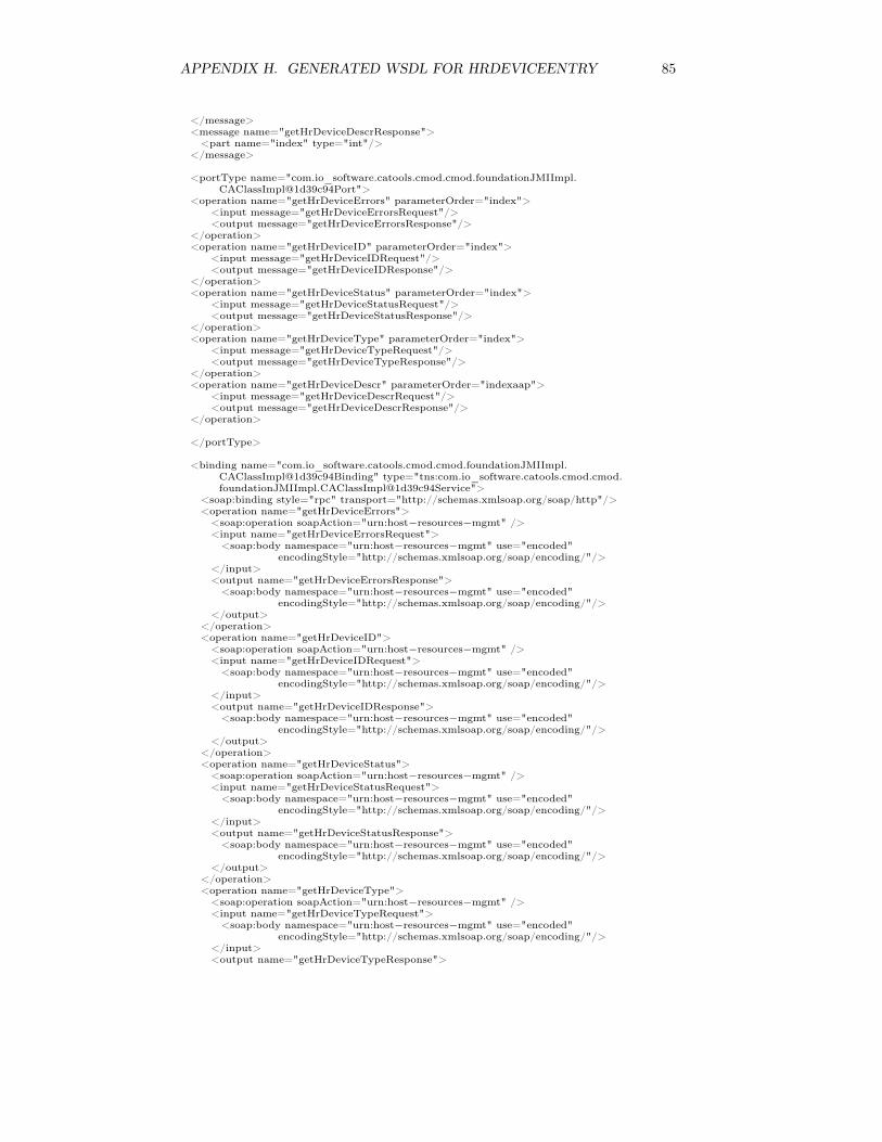
APPENDIX H. GENERATED WSDL FOR HRDEVICEENTRY 85
</message><message name="getHrDeviceDescrResponse"><part name="index" type="int"/>
</message>
<portType name="com.io_software.catools.cmod.cmod.foundationJMIImpl.CAClassImpl@1d39c94Port">
<operation name="getHrDeviceErrors" parameterOrder="index"><input message="getHrDeviceErrorsRequest"/><output message="getHrDeviceErrorsResponse"/>
</operation><operation name="getHrDeviceID" parameterOrder="index">
<input message="getHrDeviceIDRequest"/><output message="getHrDeviceIDResponse"/>
</operation><operation name="getHrDeviceStatus" parameterOrder="index">
<input message="getHrDeviceStatusRequest"/><output message="getHrDeviceStatusResponse"/>
</operation><operation name="getHrDeviceType" parameterOrder="index">
<input message="getHrDeviceTypeRequest"/><output message="getHrDeviceTypeResponse"/>
</operation><operation name="getHrDeviceDescr" parameterOrder="indexaap">
<input message="getHrDeviceDescrRequest"/><output message="getHrDeviceDescrResponse"/>
</operation>
</portType>
<binding name="com.io_software.catools.cmod.cmod.foundationJMIImpl.CAClassImpl@1d39c94Binding" type="tns:com.io_software.catools.cmod.cmod.foundationJMIImpl.CAClassImpl@1d39c94Service">
<soap:binding style="rpc" transport="http://schemas.xmlsoap.org/soap/http"/><operation name="getHrDeviceErrors"><soap:operation soapAction="urn:host−resources−mgmt" /><input name="getHrDeviceErrorsRequest"><soap:body namespace="urn:host−resources−mgmt" use="encoded"
encodingStyle="http://schemas.xmlsoap.org/soap/encoding/"/></input><output name="getHrDeviceErrorsResponse"><soap:body namespace="urn:host−resources−mgmt" use="encoded"
encodingStyle="http://schemas.xmlsoap.org/soap/encoding/"/></output>
</operation><operation name="getHrDeviceID"><soap:operation soapAction="urn:host−resources−mgmt" /><input name="getHrDeviceIDRequest"><soap:body namespace="urn:host−resources−mgmt" use="encoded"
encodingStyle="http://schemas.xmlsoap.org/soap/encoding/"/></input><output name="getHrDeviceIDResponse"><soap:body namespace="urn:host−resources−mgmt" use="encoded"
encodingStyle="http://schemas.xmlsoap.org/soap/encoding/"/></output>
</operation><operation name="getHrDeviceStatus"><soap:operation soapAction="urn:host−resources−mgmt" /><input name="getHrDeviceStatusRequest"><soap:body namespace="urn:host−resources−mgmt" use="encoded"
encodingStyle="http://schemas.xmlsoap.org/soap/encoding/"/></input><output name="getHrDeviceStatusResponse"><soap:body namespace="urn:host−resources−mgmt" use="encoded"
encodingStyle="http://schemas.xmlsoap.org/soap/encoding/"/></output>
</operation><operation name="getHrDeviceType"><soap:operation soapAction="urn:host−resources−mgmt" /><input name="getHrDeviceTypeRequest"><soap:body namespace="urn:host−resources−mgmt" use="encoded"
encodingStyle="http://schemas.xmlsoap.org/soap/encoding/"/></input><output name="getHrDeviceTypeResponse">

APPENDIX H. GENERATED WSDL FOR HRDEVICEENTRY 86
<soap:body namespace="urn:host−resources−mgmt" use="encoded"encodingStyle="http://schemas.xmlsoap.org/soap/encoding/"/>
</output></operation><operation name="getHrDeviceDescr"><soap:operation soapAction="urn:host−resources−mgmt" /><input name="getHrDeviceDescrRequest"><soap:body namespace="urn:host−resources−mgmt" use="encoded"
encodingStyle="http://schemas.xmlsoap.org/soap/encoding/"/></input><output name="getHrDeviceDescrResponse"><soap:body namespace="urn:host−resources−mgmt" use="encoded"
encodingStyle="http://schemas.xmlsoap.org/soap/encoding/"/></output>
</operation>
</binding><service><documentation> </documentation><port binding="com.io_software.catools.cmod.cmod.foundationJMIImpl.
CAClassImpl@1d39c94Binding" name="TODO"><soap:adress location="http://localhost:8080/soap/servlet/rpcrouter"/>
</port></service>
</definitions>

Bibliography
[1] William Stallings. SNMP, SNMPv2, SNMPv3, and RMON 1 and 2. Ad-dison-Wesley, Reading, MA, USA, third edition, 1999.
[2] J.P. Paulo Almeida. Web Services Development with OMG/MDAStandards.<url:https://doc.telin.nl/dscgi/ds.py/ViewProps/File-30227>,February 2003. WASP presentation (WASP/PM3.7).
[3] R. Frye, D. Levi, S. Routhier, and B. Wijnen. Coexistence between Version1, Version 2, and Version 3 of the Internet-standard Network ManagementFramework, RFC3584. RFC 3584, Internet Engineering Task Force, Au-gust 2003.
[4] J. B. Postel. User datagram protocol. RFC 768, Internet EngineeringTask Force, August 1980.
[5] Jean-Philippe Martin-Flatin. Web-Based Management of IP Networks andSystems. John Wiley & Sons, Ltd., Chichester, West Sussex, PO19 8SQ,England, 2003.
[6] Chris Wellens and Karl Auerbach. Towards useful management. TheSimple Times, 4(3):1–6, July 1996.
[7] J. Schönwälder, A. Pras, and J.P. Martin-Flatin. On the future of internetmanagement technologies. IEEE Communications Magazine, 41(10):90–97, October 2003.
[8] W3C: Extensible Markup Language.<url:http://www.w3.org/XML/>.
[9] Mi-Jung Choi, James W. Hong, and Hong-Taek Ju. XML-based NetworkManagement for IP Networks. ETRI Journal, 25(6):445–463, December2003.
[10] F. Strauß and T. Klie. Towards XML oriented internet management.In Proc. 8th IFIP/IEEE International Symposium on Integrated NetworkManagement, pages 505–518, Colorado Springs, March 2003.
[11] The Internet Engineering Task Force (IETF).<url:http://www.ietf.org>.
[12] Network Management Research Group.<url:http://www.ibr.cs.tu-bs.de/projects/nmrg/>.
87

BIBLIOGRAPHY 88
[13] Internet Research Task Force.<url:http://www.irtf.org>.
[14] Internet Architecture Board.<url:http://www.iab.org>.
[15] J. Schönwälder. Overview of the 2002 IAB Network Management Work-shop, RFC3535. RFC 3535, Internet Engineering Task Force, May 2003.
[16] IETF: Evolution of SNMP Working Group.<url:http://www.ietf.org/ietf/eos/>.
[17] IETF: Next Generation Structure of Management Information WorkingGroup.<url:http://www.ietf.org/ietf/sming/>.
[18] W3C: World Wide Web Consortium.<url:http://www.w3.org>.
[19] Frank Dzubeck. Is it time to re-engineer SNMP?<url:http://www.nwfusion.com/columnists/2004/0322dzubeck.
html>, March 2004.
[20] W3C: Web Services Activity.<url:http://www.w3.org/2002/ws/>.
[21] Object Management Group.<url:http://www.omg.org>.
[22] Jan Willem Janssen. Evaluation of current tool support for the Model-Driven Architecture. Master’s thesis, University of Twente, Enschede, TheNetherlands, January 2004.
[23] Minutes of the 11th NMRG meeting, Schloss Osnabrueck, Germany.<url:http://www.ibr.cs.tu-bs.de/projects/nmrg/minutes/
minutes-011.txt>, September 2002.
[24] Jorge E. López de Vergara, Víctor A. Villagrá, Juan I. Asensio, and JulioBerrocal. Ontologies: giving semantics to network management models.Network, IEEE, 17(3):15– 21, 2003.
[25] IETF: NETCONF Working Group.<url:http://www.ops.ietf.org/netconf/>.
[26] T. Goddard. NETCONF over SOAP. Internet-Draft, feb 2004.<url:http://www.ietf.org/internet-drafts/
draft-ietf-netconf-soap-01.txt>.
[27] Distributed Management Task Force, Inc.<url:http://www.dmtf.org>.
[28] Common Information Model standards.<url:http://www.dmtf.org/standards/cim/>.

BIBLIOGRAPHY 89
[29] CIM Managed Object Format (MOF).<url:http://www.wbemsolutions.com/tutorials/CIM/cim-mof.
html>.
[30] HP - Web Services Management Framework.<url:http://devresource.hp.com/drc/specifications/wsmf/>.
[31] OASIS Web Services Distributed Management TC.<url:http://www.oasis-open.org/committees/wsdm/>.
[32] R. Neisse, R. L. Vianna, L. Z. Granville, M. J. B. Almeida, and L. M. R.Tarouco. Implementation and Bandwidth Consumption Evaluation ofSNMP to Web Services Gateways. IEEE/IFIP Network Operations &Management Symposium, April 2004.
[33] Thomas Drevers. Performance of web services based network monitor-ing. Master’s thesis, University of Twente, Enschede, The Netherlands,January 2004.
[34] Information technology – Open Systems Interconnection – Basic ReferenceModel. ISO/IEC 7498-*.
[35] Marshall T. Rose and K. McCloghrie. Structure and identification ofmanagement information for TCP/IP-based internets. RFC 1155, InternetEngineering Task Force, May 1990.
[36] K. McCloghrie and Marshall T. Rose. Management information base fornetwork management of TCP/IP-based internets:MIB-II. RFC 1213, In-ternet Engineering Task Force, March 1991.
[37] J. D. Case, M. S. Fedor, M. L. Schoffstall, and C. Davin. Simple networkmanagement protocol (SNMP). RFC 1157, Internet Engineering TaskForce, May 1990.
[38] J. Schönwälder. Simple network management protocol over transmissioncontrol protocol transport mapping. RFC 3430, Internet Engineering TaskForce, December 2002.
[39] D. Perkins and E. McGinnis. Understanding SNMP MIBs. Prentice-Hall,Upper Saddle River, NJ, USA, 1997.
[40] K. McCloghrie and F. Kastenholz. The interfaces group MIB. RFC 2863,Internet Engineering Task Force, June 2000.
[41] Version 2 of the protocol operations for the simple network managementprotocol (SNMP). RFC 3416, Internet Engineering Task Force, December2002.
[42] W3C: Web Services Architecture.<url:http://www.w3.org/TR/ws-arch/\#whatis>, August 2003.
[43] W3C: XML Protocol Working Group.<url:http://www.w3.org/2000/xp/Group/>.

BIBLIOGRAPHY 90
[44] R. Fielding, J. Gettys, J. C. Mogul, H. Frystyk, L. Masinter, P. J. Leach,and T. Berners-Lee. Hypertext transfer protocol – HTTP/1.1. RFC 2616,Internet Engineering Task Force, June 1999.
[45] J. B. Postel and J. F. Reynolds. File transfer protocol. RFC 959, InternetEngineering Task Force, October 1985.
[46] Simple mail transfer protocol. RFC 2821, Internet Engineering Task Force,April 2001.
[47] W3C: XML Schema Part 0: Primer.<url:http://www.w3.org/TR/xmlschema-0/>, May 2001.
[48] OASIS Universal Description, Discovery and Integration TC.<url:http://www.uddi.org/>.
[49] XML-RPC Home Page.<url:http://www.xmlrpc.com/>.
[50] OMG: Common Object Request Broker Architecture.<url:http://www.corba.org>.
[51] Sun: Java Remote Method Invocation (Java RMI).<url:http://java.sun.com/products/jdk/rmi/>.
[52] Microsoft: Web Services Development Center.<url:http://msdn.microsoft.com/webservices/>.
[53] IBM: SOA and Web services.<url:http://www.ibm.com/developerworks/webservices/>.
[54] Sun: Java Technology and Web Services.<url:http://java.sun.com/webservices/>.
[55] Novell: Novell exteNd.<url:http://www.novell.com/webservices/>.
[56] BEA: Web services and WebLogic.<url:http://dev2dev.bea.com/technologies/webservices/>.
[57] Web Services Project @ Apache.<url:http://ws.apache.org>.
[58] W3C: Web Services Description Language (WSDL) Version 2.0 Part 1:Core Language.<url:http://www.w3.org/TR/wsdl20/>, March 2004.
[59] OMG: Unified Modelling Language.<url:http://www.omg.org/uml/>.
[60] David Frankel. Using Model-Driven Architecture to Develop Web Services(White Paper).<url:http://www.iona.com/archwebservice/WSMDA.pdf>, April 2002.
[61] OMG: Model-Driven Architecture.<url:http://www.omg.org/mda/>.

BIBLIOGRAPHY 91
[62] Joaquin Miller and Jishnu Mukerji. MDA Guide Version 1.0.1.<url:http://www.omg.org/cgi-bin/apps/doc?omg/03-06-01.pdf>,June 2003.
[63] Joaquin Miller and Jishnu Mukerji. Model Driven Architecture (MDA).<url:http://www.omg.org/cgi-bin/doc?ormsc/2001-07-01>, July2001. Document number ormsc/2001-07-01.
[64] Meta-Object Facility (MOF) Specification, version 1.4.<url:http://www.omg.org/cgi-bin/doc?formal/2002-04-03>, April2002.
[65] J. B. Postel. Transmission control protocol. RFC 793, Internet Engineer-ing Task Force, September 1981.
[66] W3C: Web Services Description Language (WSDL) Version 2.0 Part 2:Message Patterns.<url:http://www.w3.org/TR/wsdl20-patterns>, March 2004.
[67] Publish/subscribe networking.<url:http://www.nwfusion.com/details/6165.html>, May 2003.
[68] Drew Bird. SNMP - Anything But Simple.<url:http://networking.earthweb.com/netsp/article.php/
979991>, February 2002.
[69] OASIS Web Services Security TC.<url:http://www.oasis-open.org/committees/wss/>.
[70] Microsoft: Web Services Security (WS-Security).<url:http://msdn.microsoft.com/ws/2002/04/Security/>.
[71] OASIS Security Assertion Markup Language (SAML) v1.1.<url:http://www.oasis-open.org/committees/download.php/3400/
>.
[72] W3C: XML Signature WG.<url:http://www.w3.org/Signature/>.
[73] W3C: XML Encryption WG.<url:http://www.w3.org/Encryption/>.
[74] W3C: XML Key Management Specification (XKMS).<url:http://www.w3.org/TR/xkms/>, March 2001.
[75] E. Rescorla. HTTP over TLS. RFC 2818, Internet Engineering TaskForce, May 2000.
[76] S/MIME version 3 message specification. RFC 2633, Internet EngineeringTask Force, June 1999.
[77] W3C Note: Web Service Choreography Interface (WSCI) 1.0.<url:http://www.w3.org/TR/wsci/>, August 2002.
[78] OASIS Web Services Business Process Execution Language TC.<url:http://www.oasis-open.org/committees/wsbpel/>.
BIBLIOGRAPHY 92
[79] BEA/IBM/Microsoft: Web Services Transaction (WS-Transaction).<url:http://msdn.microsoft.com/ws/2002/08/wstx/>.
[80] Web Services Atomic Transaction (WS-AtomicTransaction).<url:http://msdn.microsoft.com/ws/2003/09/wsat/>.
[81] BEA/IBM/Microsoft: Web Services Coordination (WSCoordination).<url:http://ftpna2.bea.com/pub/downloads/
ws-standards-coordination.pdf>.
[82] Standards for Business Process Modeling, Collaboration, and Choreogra-phy.<url:http://xml.coverpages.org/bpm.html>.
[83] Mike Champion. Proposed text on reliability in the web services archi-tecture.<url:http://lists.w3.org/Archives/Public/www-ws-arch/
2003Jan/0256.html>, January 2003. Personal contribution on W3C WSarchitecture mailing list.
[84] Web Services Reliability (WS-Reliability) Version 1.0.<url:http://developers.sun.com/sw/platform/technologies/
ws-reliability.html>.
[85] OASIS Web Services Reliable Messaging TC.<url:http://www.oasis-open.org/committees/wsrm/>.
[86] K. McCloghrie and F. Kastenholz. The interfaces group MIB using SMIv2.RFC 2233, Internet Engineering Task Force, November 1997.
[87] P. Grillo and S. Waldbusser. Host resources MIB. RFC 2790, InternetEngineering Task Force, March 2000.
[88] Avaya Labs Research - XML based Mgmt Interface.<url:http://www.research.avayalabs.com/user/mazum/Projects/
XML/>.
[89] Microsoft: Distributed Systems Patterns.<url:http://msdn.microsoft.com/library/en-us/dnpatterns/
html/EspDistributedSystemsPatternsCluster.asp>.
[90] Aiko Pras and Juergen Schönwälder. On the difference between informa-tion models and data models. RFC 3444, Internet Engineering Task Force,January 2003.
[91] A. Westerinen, J. Schnizlein, J. Strassner, M. Scherling, B. Quinn, S. Her-zog, A. Huynh, and M. Carlson. Terminology for policy-based manage-ment. RFC 3198, Internet Engineering Task Force, November 2001.
[92] Aiko Pras. Network management architectures. PhD thesis, University ofTwente, Enschede, The Netherlands, February 1995.
[93] M. Tamer Özsu and Patrick Valduriez. Principles of distributed databasesystems. Prentice-Hall, Upper Saddle River, NJ 07458, USA, second edi-tion, 1999.

BIBLIOGRAPHY 93
[94] Information technology – Database languages – SQL. ISO/IEC 9075-*:2003, 2003.
[95] Jeffrey D. Ullman and Jennifer Widon. A first course in database systems.Prentice-Hall, Upper Saddle River, NJ 07458, USA, 1997.
[96] Roger S. Pressman. Software Engineering: A Practitioner’s Approach.McGraw-Hill, London, fourth edition, 1997. European Adaptation.Adapted by Darrel Ince.
[97] NMRG Views of an IETF Information Model.<url:http://www.ibr.cs.tu-bs.de/projects/nmrg/infomodel/>.
[98] J. Schönwälder and A. Müller. Reverse engineering internet MIBs.<url:http://www.ibr.cs.tu-bs.de/vs/papers/im-2001.pdf>.
[99] libsmi - A Library to Access SMI MIB Information.<url:http://www.ibr.cs.tu-bs.de/projects/libsmi/>.
[100] Interactive Objects Software: ArcStyler.<url:http://www.arcstyler.com>.
[101] Marshall T. Rose and Keith McCloghrie. How to Manage Your NetworkUsing SNMP: The Networking Management Practicum. Prentice-Hall,Englewood Cliffs, NJ 07632, USA, January 1995.
[102] Dia: a drawing program.<url:http://www.gnome.org/projects/dia/>.
[103] The Apache Jakarta Project.<url:http://jakarta.apache.org>.