Embed Size (px)
Citation preview
Magnetic precision has a name
NMR Precision Teslameter
PT2026
User's Manual
Version 2.1
(Revision 1.0)
March 2017
PT2026 User’s Manual v 2.1 r 1.0 – 03/2017 Copyright © 2017 Metrolab Technology SA
ii www.metrolab.com
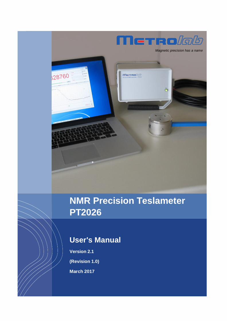
REVISION HISTORY
v. 1.0 r. 1.0 August 2015
First release
v. 1.1 r. 1.0 January 2016
Mention MFC API coding example
Update definition of *IDN? output
Add warning about NMR signal averaging
Explain effect of NMR pulse parameters
Add description of back panel
Update specifications
Miscellaneous editorial changes
v. 1.2 r. 1.0 March 2016
Change description for new recording file format
API is now in LabVIEW 2015 SP1 format
v. 1.3 r. 1.0 June 2016 Add description of “Probe Info” button
Update installation procedure for signed installer
Fix numbering of help bullets
v. 2.0 r. 1.0 March 2017
Move safety and EMC relevant information into Installation and Safety Manual
Software UIF changes:
1. General: colors of numeric display
2. General: change gyromagnetic ratio used for MHz-p units, from free to shielded proton.
3. Parameters > Search & Averaging: Hall Enable
4. Advanced > Match & Tune: new screen shot
API changes:
1. Fetch VIs return associated measurement status
2. Fetch Search Progress VI returns Hall value
3. Add Power Off VI
4. Read Probe Data VI returns Designation information
5. Add Configure Search Hall and Configure Search Hall VIs
6. Add Utility/Manufacturing VIs
SCPI command changes:
1. :FETCh[:SCALar]:SPRogress? returns Hall value
PT2026 User’s Manual v 2.1 r 1.0 – 03/2017 Copyright © 2017 Metrolab Technology SA
iii www.metrolab.com
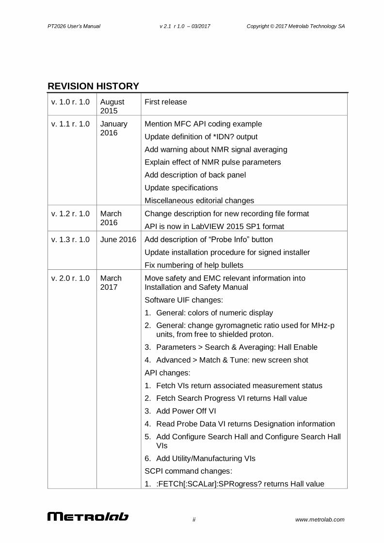
2. Add :FETCh[:SCALar]:STATus? and :FETCh:ARRay:STATus? queries
3. Add :CONFigure:SEARch:HALLenable and query
4. Add :SYSTem:POFF command
5. Add :ROUTe:PROBe:DESignation? query
6. Change :ROUT:PROBe:LOWLevel to :ROUT:LOWLevel
7. Add :ROUT:MMEM:DATA command and query
8. Add :DIAGnostic:LOG[:DATA]? Query
v. 2.1 r. 1.0 March 2017
Restructure :ROUTe:PROBe:HALL commands
Add “Raw Hall” instance of Read Probe Data VI
PT2026 User’s Manual v 2.1 r 1.0 – 03/2017 Copyright © 2017 Metrolab Technology SA
iv www.metrolab.com
CONTENTS
1- INTRODUCTION ............................................................................................................................................... 1
2- QUICK START GUIDE ..................................................................................................................................... 3
2-1 SOFTWARE INSTALLATION – WINDOWS ......................................................................................................... 3 2-2 START-UP ........................................................................................................................................................... 7 2-3 SHUT-DOWN ...................................................................................................................................................... 8 2-4 CONNECT VIA ETHERNET .................................................................................................................................. 9 2-5 USING MULTIPLEXERS .................................................................................................................................... 12
3- OVERVIEW ...................................................................................................................................................... 14
3-1 MEASUREMENT ............................................................................................................................................... 14 3-2 INTERFACES ..................................................................................................................................................... 16
4- SOFTWARE USER INTERFACE ................................................................................................................. 18
4-1 GENERAL .......................................................................................................................................................... 18 4-2 PLOT DISPLAY ................................................................................................................................................. 21 4-3 PARAMETERS > SEARCH & AVERAGING ....................................................................................................... 23 4-4 PARAMETERS > TRIGGER IN .......................................................................................................................... 25 4-5 PARAMETERS > TRIGGER OUT ...................................................................................................................... 26 4-6 PARAMETERS > DISPLAY ............................................................................................................................... 27 4-7 ADVANCED > SEARCH & AVERAGING ........................................................................................................... 28 4-8 ADVANCED > MEASURE.................................................................................................................................. 29 4-9 ADVANCED > RF PULSE ................................................................................................................................. 30 4-10 ADVANCED > ACQUISITION ............................................................................................................................ 31 4-11 ADVANCED > MATCH & TUNE ....................................................................................................................... 32 4-12 FILE .................................................................................................................................................................. 33 4-13 SETUP ............................................................................................................................................................... 34
5- LABVIEW INSTRUMENT DRIVER ........................................................................................................... 36
5-1 INSTALLATION ................................................................................................................................................. 36 5-2 OVERVIEW OF DRIVER INTERFACE ............................................................................................................... 37 5-3 APPLICATION TEMPLATE ............................................................................................................................... 37 5-4 SAMPLE CODE.................................................................................................................................................. 38 5-5 STANDARD INPUTS AND OUTPUTS ................................................................................................................ 39 5-6 INITIALIZE AND CLOSE.................................................................................................................................... 40 5-6-1 INITIALIZE.VI ......................................................................................................................................................................... 40 5-6-2 CLOSE.VI .................................................................................................................................................................................. 40 5-7 CONFIGURE ...................................................................................................................................................... 41 5-7-1 CONFIGURE AVERAGING.VI ................................................................................................................................................ 41 5-7-2 CONFIGURE INPUT TRIGGER COUNT.VI.......................................................................................................................... 41 5-7-3 CONFIGURE INPUT TRIGGER.VI ........................................................................................................................................ 41 5-7-4 CONFIGURE MEASURE.VI.................................................................................................................................................... 41 5-7-5 CONFIGURE OUTPUT TRIGGER.VI .................................................................................................................................... 42 5-7-6 CONFIGURE PPM REFERENCE.VI..................................................................................................................................... 42 5-7-7 CONFIGURE ROUTE.VI ......................................................................................................................................................... 42 5-7-1 CONFIGURE SEARCH HALL.VI............................................................................................................................................ 42 5-7-2 CONFIGURE SEARCH LIMITS.VI ......................................................................................................................................... 42 5-7-3 CONFIGURE SEARCH.VI ....................................................................................................................................................... 43 5-7-4 CONFIGURE UNIT.VI............................................................................................................................................................. 43 5-8 CONFIGURE – ADVANCED ............................................................................................................................... 43 5-8-1 CONFIGURE CLOCK SOURCE.VI ......................................................................................................................................... 43
PT2026 User’s Manual v 2.1 r 1.0 – 03/2017 Copyright © 2017 Metrolab Technology SA
v www.metrolab.com
5-8-2 CONFIGURE DIGITIZATION.VI ............................................................................................................................................ 43 5-8-3 CONFIGURE FORMAT.VI ...................................................................................................................................................... 44 5-8-4 CONFIGURE MATCHING-TUNING.VI ................................................................................................................................ 44 5-8-5 CONFIGURE PULSE.VI .......................................................................................................................................................... 44 5-9 CONFIGURE – COMMUNICATION .................................................................................................................... 44 5-9-1 CONFIGURE ETHERNET.VI ................................................................................................................................................. 44 5-9-2 CONFIGURE MODBUS.VI...................................................................................................................................................... 45 5-9-3 CONFIGURE USB.VI .............................................................................................................................................................. 45 5-9-4 CONFIGURE VXI11.VI ......................................................................................................................................................... 45 5-10 ACTION-STATUS.............................................................................................................................................. 45 5-10-1 ABORT.VI .............................................................................................................................................................................. 45 5-10-2 CHANGE MANUAL SEARCH VALUE.VI .......................................................................................................................... 45 5-10-3 FETCH SEARCH PROGRESS.VI ......................................................................................................................................... 45 5-10-4 FORCE OPERATION COMPLETE.VI................................................................................................................................. 46 5-10-5 FORCE OUTPUT TRIGGER.VI ........................................................................................................................................... 46 5-10-6 INITIATE.VI .......................................................................................................................................................................... 46 5-10-7 PRESET STATUS.VI............................................................................................................................................................. 46 5-10-8 QUERY ARBITRARY STATUS.VI ...................................................................................................................................... 46 5-10-9 QUERY CURRENT ROUTE.VI ............................................................................................................................................ 46 5-10-10 QUERY STATUS OPERATION BITX.VI ........................................................................................................................ 47 5-10-11 QUERY STATUS OPERATION.VI.................................................................................................................................... 47 5-10-12 QUERY STATUS QUESTIONABLE BITX.VI ................................................................................................................. 47 5-10-13 QUERY STATUS QUESTIONABLE.VI ............................................................................................................................ 47 5-10-14 QUERY STATUS STANDARD EVENT.VI ....................................................................................................................... 48 5-10-15 REGISTER TO SRQ.VI ..................................................................................................................................................... 48 5-10-16 SET TRANSITION FILTER.VI.......................................................................................................................................... 48 5-10-17 UNREGISTER FROM SRQ.VI.......................................................................................................................................... 48 5-10-18 WAIT FOR OPERATION TO COMPLETE.VI ................................................................................................................ 49 5-11 DATA ................................................................................................................................................................ 49 5-11-1 FETCH.VI............................................................................................................................................................................... 49 5-11-2 MEASURE FLUX.VI ............................................................................................................................................................. 51 5-11-3 READ CHANNEL LIST.VI ................................................................................................................................................... 51 5-11-4 READ PROBE DATA.VI ...................................................................................................................................................... 52 5-12 DATA – CONFIGURATION ............................................................................................................................... 52 5-12-1 QUERY CLOCK SOURCE.VI................................................................................................................................................ 52 5-12-2 QUERY CONTINUOUS STATE.VI ...................................................................................................................................... 52 5-12-3 QUERY DIGITIZATION CONFIGURATION.VI ................................................................................................................. 53 5-12-4 QUERY ETHERNET CONFIGURATION.VI....................................................................................................................... 53 5-12-5 QUERY FORMAT.VI ............................................................................................................................................................ 54 5-12-6 QUERY INPUT TRIGGER CONFIGURATION.VI ............................................................................................................. 54 5-12-7 QUERY MATCHING-TUNING CONFIGURATION.VI ..................................................................................................... 55 5-12-8 QUERY MEASURE CONFIGURATION.VI......................................................................................................................... 56 5-12-9 QUERY MEASUREMENT AVERAGING CONFIGURATION.VI...................................................................................... 58 5-12-10 QUERY MODBUS CONFIGURATION.VI ........................................................................................................................ 58 5-12-11 QUERY OUTPUT TRIGGER CONFIGURATION.VI ....................................................................................................... 59 5-12-12 QUERY PULSE CONFIGURATION.VI ............................................................................................................................. 60 5-12-13 QUERY SEARCH CONFIGURATION.VI .......................................................................................................................... 61 5-12-1 CONFIGURE SEARCH HALL.VI ......................................................................................................................................... 62 5-12-2 QUERY SIGNAL AVERAGING CONFIGURATION.VI ...................................................................................................... 62 5-12-3 QUERY UNIT CONFIGURATION.VI .................................................................................................................................. 63 5-12-4 QUERY USB CONFIGURATION.VI ................................................................................................................................... 63 5-12-5 QUERY VXI11 CONFIGURATION.VI .............................................................................................................................. 63 5-13 UTILITY ............................................................................................................................................................ 63 5-13-1 ERROR QUERY.VI ............................................................................................................................................................... 63 5-13-2 FIND INSTRUMENTS.VI ..................................................................................................................................................... 63
PT2026 User’s Manual v 2.1 r 1.0 – 03/2017 Copyright © 2017 Metrolab Technology SA
vi www.metrolab.com
5-13-3 LOCK-UNLOCK.VI ............................................................................................................................................................... 64 5-13-4 POWER OFF.VI .................................................................................................................................................................... 64 5-13-5 READ CASE TEMPERATURE.VI ....................................................................................................................................... 64 5-13-6 READ FILE DIRECTORY.VI ............................................................................................................................................... 64 5-13-7 READ FILE.VI ....................................................................................................................................................................... 64 5-13-8 READ MANUFACTURING AND CALIBRATION DATES.VI .......................................................................................... 65 5-13-9 RECALL INSTRUMENT SETTINGS.VI .............................................................................................................................. 65 5-13-10 RESET.VI ............................................................................................................................................................................ 65 5-13-11 REVISION QUERY.VI ........................................................................................................................................................ 65 5-13-12 SAVE INSTRUMENT SETTINGS.VI ................................................................................................................................ 65 5-13-13 UPGRADE.VI ...................................................................................................................................................................... 65 5-13-14 WRITE-DELETE FILE.VI ................................................................................................................................................ 66 5-14 UTILITY – CONVERSION.................................................................................................................................. 66 5-14-1 BINARYTOCHANNELLIST.VI ........................................................................................................................................... 66 5-14-2 BINARYTOX16.VI .............................................................................................................................................................. 66 5-14-3 BINARYTOX16ARR.VI...................................................................................................................................................... 66 5-14-4 BINARYTOX32.VI .............................................................................................................................................................. 66 5-14-5 BINARYTOX32ARR.VI...................................................................................................................................................... 67 5-14-6 BINARYTOX64.VI .............................................................................................................................................................. 67 5-14-7 BINARYTOX64ARR.VI...................................................................................................................................................... 67 5-14-8 FROMARBITRARYBLOCK.VI ............................................................................................................................................ 67 5-14-9 FROMRAWCHANNELLIST.VI........................................................................................................................................... 67 5-14-10 ISARBITRARYBLOCK.VI ................................................................................................................................................. 68 5-14-11 PICKCHANNELFROMLIST.VI ........................................................................................................................................ 68 5-14-12 TOARBITRARYBLOCK.VI ............................................................................................................................................... 68 5-14-13 TORAWCHANNELLIST.VI .............................................................................................................................................. 68 5-15 UTILITY – MANUFACTURING ......................................................................................................................... 69 5-15-1 READ DEVICE ROM.VI ..................................................................................................................................................... 69 5-15-1 TRANSFER LOWLEVEL DEVICE DATA.VI .................................................................................................................... 69 5-15-1 WRITE DEVICE ROM.VI................................................................................................................................................... 69
6- HOST INTERFACES ...................................................................................................................................... 70
6-1 GENERAL .......................................................................................................................................................... 70 6-2 NATIVE INTERFACES ....................................................................................................................................... 71 6-2-1 SCPI INSTRUMENT MODEL ................................................................................................................................................ 71 6-2-2 IEEE 488.2 / SCPI STATUS REGISTERS ....................................................................................................................... 73 6-2-3 IEEE 488.2 CONTROLS ...................................................................................................................................................... 78 6-2-4 IEEE 488.2 COMMON COMMANDS ................................................................................................................................. 79 6-2-5 SCPI COMMAND SYNTAX .................................................................................................................................................... 80 6-2-6 SCPI COMMAND SUMMARY................................................................................................................................................ 82 6-2-7 PROGRAMMING HINTS...................................................................................................................................................... 107 6-2-8 ERROR CODES ..................................................................................................................................................................... 110 6-3 MODBUS INTERFACE ................................................................................................................................. 113 6-3-1 OPERATIONAL OVERVIEW ............................................................................................................................................... 113 6-3-2 CHANNEL MAPPING ........................................................................................................................................................... 116 6-3-3 HOLDING REGISTER MAP ................................................................................................................................................. 116 6-3-4 INPUT REGISTER MAP...................................................................................................................................................... 117
7- KEY SPECIFICATIONS .............................................................................................................................. 119
7-1 MEASUREMENT ............................................................................................................................................ 119 7-2 PROBES ......................................................................................................................................................... 119 7-3 SOFTWARE .................................................................................................................................................... 119
8- NMR MAGNETOMETERS ......................................................................................................................... 120

PT2026 User’s Manual v 2.1 r 1.0 – 03/2017 Copyright © 2017 Metrolab Technology SA
vii www.metrolab.com
8-1 NMR: A DISCOVERY DESTINED FOR GREATNESS ...................................................................................... 120 8-2 THE INGREDIENTS FOR AN NMR MAGNETOMETER .................................................................................. 121 8-3 PROS AND CONS ............................................................................................................................................ 124 8-4 MORE IS BETTER .......................................................................................................................................... 125 8-5 BETTER IS BETTER ....................................................................................................................................... 126 8-6 EVEN LESS CAN BE BETTER .......................................................................................................................... 128
PT2026 User’s Manual v 2.1 r 1.0 – 03/2017 Copyright © 2017 Metrolab Technology SA
1 www.metrolab.com
GETTING STARTED
1- Introduction
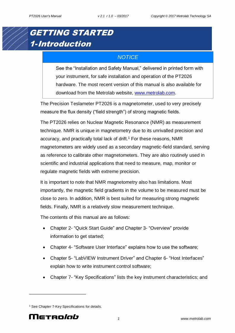
NOTICE
See the “Installation and Safety Manual,” delivered in printed form with
your instrument, for safe installation and operation of the PT2026
hardware. The most recent version of this manual is also available for
download from the Metrolab website, www.metrolab.com.
The Precision Teslameter PT2026 is a magnetometer, used to very precisely
measure the flux density (“field strength”) of strong magnetic fields.
The PT2026 relies on Nuclear Magnetic Resonance (NMR) as measurement
technique. NMR is unique in magnetometry due to its unrivalled precision and
accuracy, and practically total lack of drift.1 For these reasons, NMR
magnetometers are widely used as a secondary magnetic-field standard, serving
as reference to calibrate other magnetometers. They are also routinely used in
scientific and industrial applications that need to measure, map, monitor or
regulate magnetic fields with extreme precision.
It is important to note that NMR magnetometry also has limitations. Most
importantly, the magnetic field gradients in the volume to be measured must be
close to zero. In addition, NMR is best suited for measuring strong magnetic
fields. Finally, NMR is a relatively slow measurement technique.
The contents of this manual are as follows:
Chapter 2- “Quick Start Guide” and Chapter 3- “Overview” provide
information to get started;
Chapter 4- “Software User Interface” explains how to use the software;
Chapter 5- “LabVIEW Instrument Driver” and Chapter 6- “Host Interfaces”
explain how to write instrument control software;
Chapter 7- “Key Specifications” lists the key instrument characteristics; and
1 See Chapter 7-Key Specifications for details.

PT2026 User’s Manual v 2.1 r 1.0 – 03/2017 Copyright © 2017 Metrolab Technology SA
2 www.metrolab.com
Chapter 8- “NMR Magnetometers” provides technical background information
on NMR magnetometers.
Updates to the software, firmware and documentation are posted on the Metrolab
website, www.metrolab.com, and can be downloaded free of charge. The
firmware in the PT2026 Main Unit can be upgraded in the field. The easiest way to
be notified of updates is to sign up for our electronic newsletter, on the News page
of our site.
We hope the PT2026 will help you perform your magnetic field measurements
easily and accurately. If you have problems and your reseller cannot help you
further, the Metrolab team is ready to help. Even if you don’t have problems, we
are always interested in knowing more about how our instruments are used. Feel
free to contact us at any time at [email protected].
PT2026 User’s Manual v 2.1 r 1.0 – 03/2017 Copyright © 2017 Metrolab Technology SA
3 www.metrolab.com
GETTING STARTED
2- Quick Start Guide
This chapter describes the installation, start-up and shut-down of the PT2026 software. The hardware installation is described in the “PT2026 Installation and Safety Manual.”
2-1 SOFTWARE INSTALLATION – WINDOWS
Insert the installation CD.
Execute the PT2026 installation program:
\Metrolab PT2026 Windows Installer\setup.exe
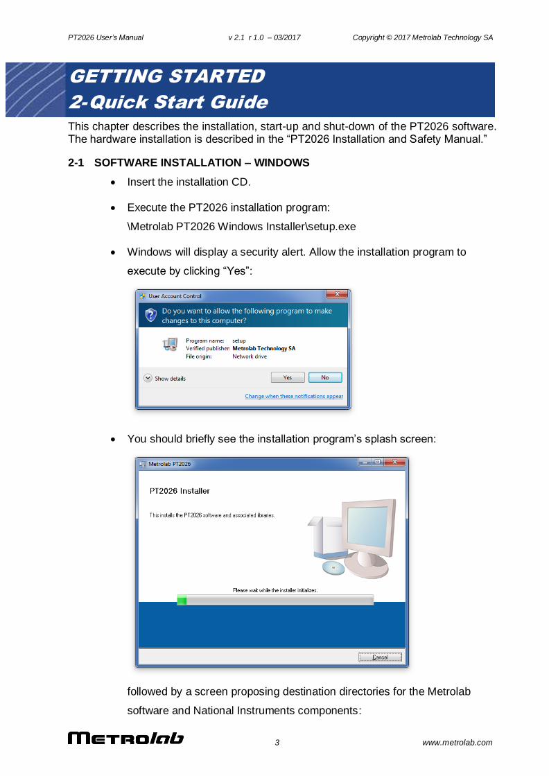
Windows will display a security alert. Allow the installation program to
execute by clicking “Yes”:
You should briefly see the installation program’s splash screen:
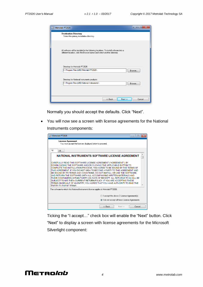
followed by a screen proposing destination directories for the Metrolab
software and National Instruments components:
PT2026 User’s Manual v 2.1 r 1.0 – 03/2017 Copyright © 2017 Metrolab Technology SA
4 www.metrolab.com
Normally you should accept the defaults. Click “Next”.
You will now see a screen with license agreements for the National
Instruments components:
Ticking the “I accept…” check box will enable the “Next” button. Click
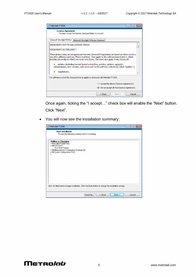
“Next” to display a screen with license agreements for the Microsoft
Silverlight component:
PT2026 User’s Manual v 2.1 r 1.0 – 03/2017 Copyright © 2017 Metrolab Technology SA
5 www.metrolab.com
Once again, ticking the “I accept…” check box will enable the “Next” button.
Click “Next”.
You will now see the installation summary:
PT2026 User’s Manual v 2.1 r 1.0 – 03/2017 Copyright © 2017 Metrolab Technology SA
6 www.metrolab.com
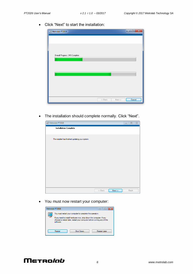
Click “Next” to start the installation:
The installation should complete normally. Click “Next”.
You must now restart your computer:
PT2026 User’s Manual v 2.1 r 1.0 – 03/2017 Copyright © 2017 Metrolab Technology SA
7 www.metrolab.com
2-2 START-UP
Power on the PT2026 as described in the PT2026 Installation and Safety
Manual.
Start the PT2026 software from the Windows Start Menu:
Metrolab > PT2026 > Metrolab PT2026
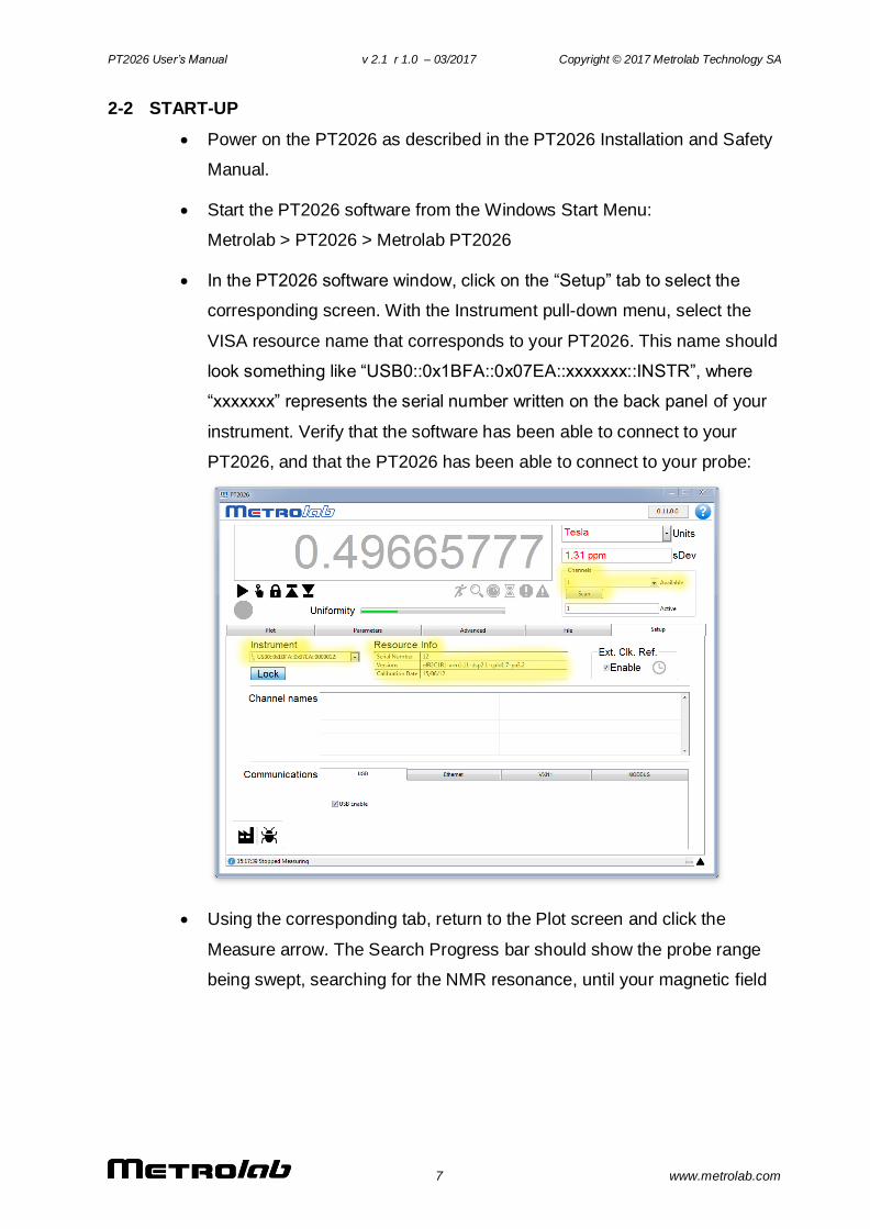
In the PT2026 software window, click on the “Setup” tab to select the
corresponding screen. With the Instrument pull-down menu, select the
VISA resource name that corresponds to your PT2026. This name should
look something like “USB0::0x1BFA::0x07EA::xxxxxxx::INSTR”, where
“xxxxxxx” represents the serial number written on the back panel of your
instrument. Verify that the software has been able to connect to your
PT2026, and that the PT2026 has been able to connect to your probe:
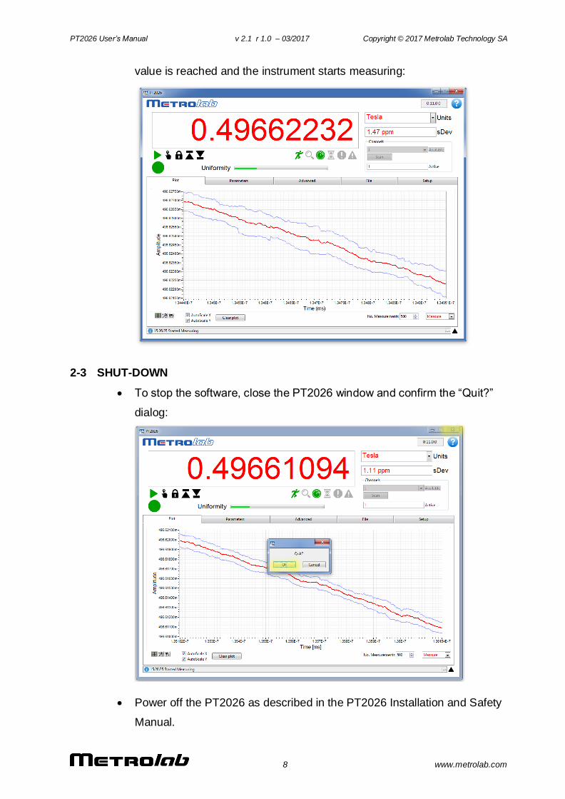
Using the corresponding tab, return to the Plot screen and click the
Measure arrow. The Search Progress bar should show the probe range
being swept, searching for the NMR resonance, until your magnetic field
PT2026 User’s Manual v 2.1 r 1.0 – 03/2017 Copyright © 2017 Metrolab Technology SA
8 www.metrolab.com
value is reached and the instrument starts measuring:
2-3 SHUT-DOWN
To stop the software, close the PT2026 window and confirm the “Quit?”
dialog:
Power off the PT2026 as described in the PT2026 Installation and Safety
Manual.
PT2026 User’s Manual v 2.1 r 1.0 – 03/2017 Copyright © 2017 Metrolab Technology SA
9 www.metrolab.com
2-4 CONNECT VIA ETHERNET
To connect to the PT2026 via Ethernet, you must first create a network instrument
entry for the PT2026 in the VISA database. Use the National Instruments utility,
“Measurement & Automation Explorer” (MAX) to do this:
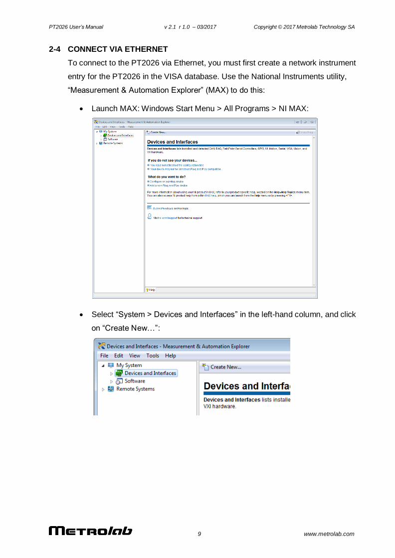
Launch MAX: Windows Start Menu > All Programs > NI MAX:
Select “System > Devices and Interfaces” in the left-hand column, and click
on “Create New…”:
PT2026 User’s Manual v 2.1 r 1.0 – 03/2017 Copyright © 2017 Metrolab Technology SA
10 www.metrolab.com
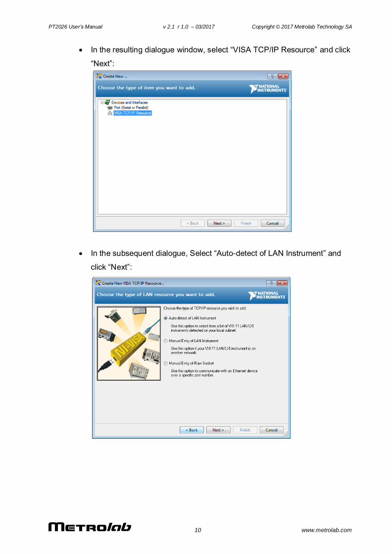
In the resulting dialogue window, select “VISA TCP/IP Resource” and click
“Next”:
In the subsequent dialogue, Select “Auto-detect of LAN Instrument” and
click “Next”:
PT2026 User’s Manual v 2.1 r 1.0 – 03/2017 Copyright © 2017 Metrolab Technology SA
11 www.metrolab.com
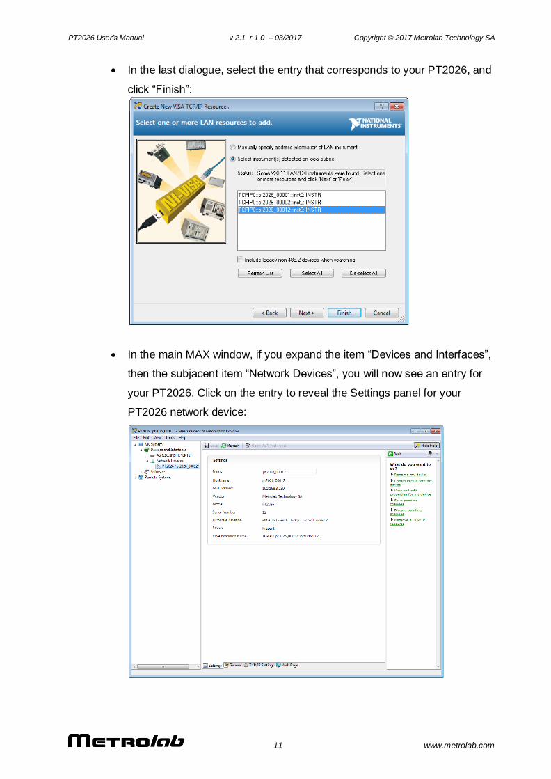
In the last dialogue, select the entry that corresponds to your PT2026, and
click “Finish”:
In the main MAX window, if you expand the item “Devices and Interfaces”,
then the subjacent item “Network Devices”, you will now see an entry for
your PT2026. Click on the entry to reveal the Settings panel for your
PT2026 network device:
PT2026 User’s Manual v 2.1 r 1.0 – 03/2017 Copyright © 2017 Metrolab Technology SA
12 www.metrolab.com
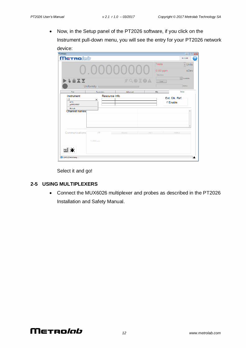
Now, in the Setup panel of the PT2026 software, if you click on the
Instrument pull-down menu, you will see the entry for your PT2026 network
device:
Select it and go!
2-5 USING MULTIPLEXERS
Connect the MUX6026 multiplexer and probes as described in the PT2026
Installation and Safety Manual.
PT2026 User’s Manual v 2.1 r 1.0 – 03/2017 Copyright © 2017 Metrolab Technology SA
13 www.metrolab.com
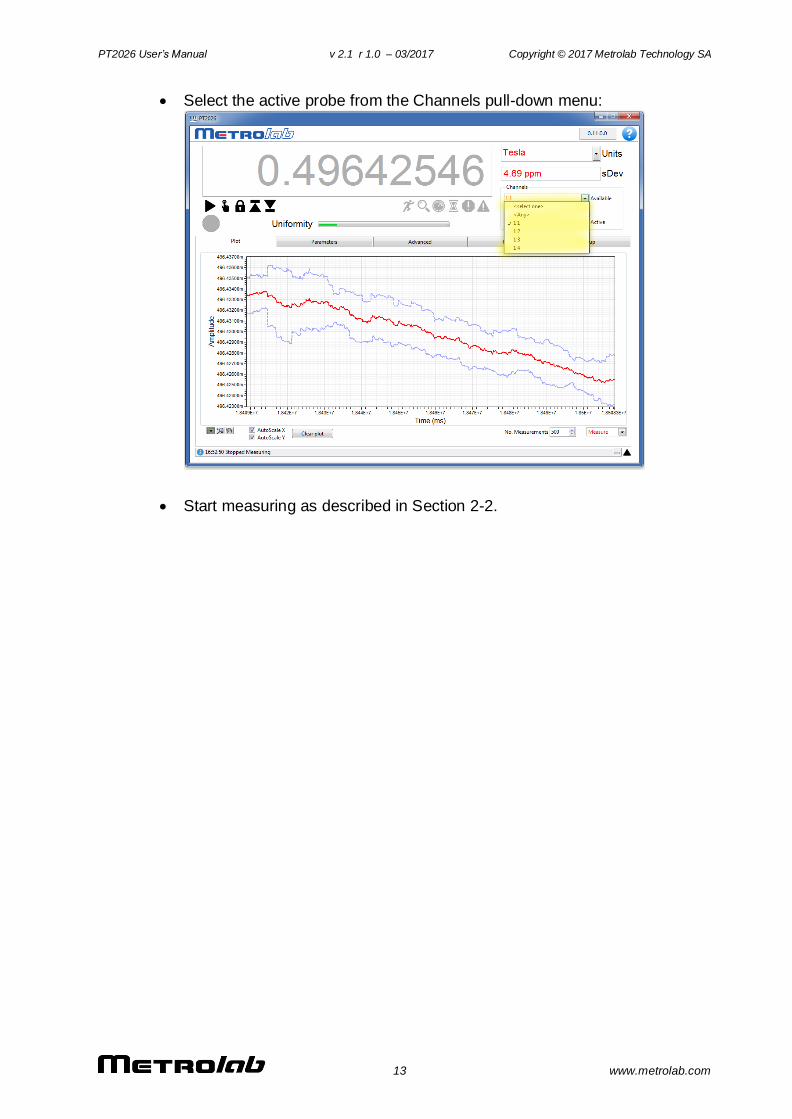
Select the active probe from the Channels pull-down menu:
Start measuring as described in Section 2-2.
PT2026 User’s Manual v 2.1 r 1.0 – 03/2017 Copyright © 2017 Metrolab Technology SA
14 www.metrolab.com
USING THE PT2026
3- Overview
This chapter provides a quick overview of what you can do with the PT2026.
Additional details are provided in subsequent chapters. Note that the contextual
help in the PT2026 software is very useful; in fact, it is exactly the same as
Chapter 4- “Software User Interface”.
3-1 MEASUREMENT
You can measure magnetic flux density with a precision of parts per million
(10-6) or even better – but beware of the limitations of NMR magnetometers
(see Section 8-3).
Before starting to measure the flux density, NMR magnetometers must find
the NMR resonance. The software tells you what the PT2026 is doing with
a status light, a series of status symbols, a search progress bar, and a
message log (see Section 4-1).
If for some reason the PT2026 cannot find the NMR resonance, you can
limit the search range (see Section 4-3). If all else fails, you can manually
force it to search at a given field strength (see Section 4-1).
Once the NMR resonance has been found and the PT2026 is measuring,
the search progress bar turns into a field-uniformity display, to help you
position the probe in your magnet’s “sweet spot” (see Section 4-1).
The software will display the measurements numerically and plot the
results on a strip chart. You can freeze the numeric display and change its
resolution (see Sections 4-1 and 4-6), and you can manipulate many
features of the plot. Some of the plot options, such as the auto-scaling
controls, are evident; others, such as the cursor controls, are accessed by
right-clicking on the plot (see Section 4-2).
You can select the appropriate measurement units, such as Tesla or
kGauss. The choices also include some exotic but useful units, such as
MHz, MHz-proton and parts per million (see Section 4-1).
PT2026 User’s Manual v 2.1 r 1.0 – 03/2017 Copyright © 2017 Metrolab Technology SA
15 www.metrolab.com
You can enable measurement averaging and display the standard
deviation of the measurements. You can control the averaging method and
the filter length (see Sections 4-1 and 4-3).
If you are using a probe multiplexer, you use the PT2026 software to select
which probe to use (see Section 4-1).
With a multiplexer, you can also group a set of probes – for example those
in a particular magnet – as a single logical channel. The PT2026 will
search across the range of each probe in turn, and will start measuring with
the one where it finds the NMR resonance. The PT2026 comes with one
pre-configured logical channel, Any, which includes all probes that are
plugged in. (See Section 4-13).
To help you find the peak field in a volume, you can have the PT2026
software display only maximum or minimum field values (see Section 4-1).
You can have the measurements triggered either continuously, at regular
intervals, via the software interface, or via a TTL signal (see Section 4-4).
You can also have the PT2026 generate an output trigger when a particular
field value is attained (See Section 4-5). The PT2026 only has a single
Trigger connector, configured either as input or output, so the output trigger
cannot be used at the same time as the TTL measurement trigger.
If need be, you can optimize the measurements by manipulating a host of
internal parameters using the Advanced tab (see Sections 4-7 through 4-
10). Unless you are very familiar with the instrument and the principles of
NMR, you probably should not touch these. A possible exception is the
Advanced > RF Pulse > Period, to increase the measurement rate (see
Section 4-9).
You can store and recall your favorite settings (see Section 4-3).
You can record and play back measurements (see Section 4-12).
Finally, the Setup tab embodies a host of useful utility features that deserve
browsing.
PT2026 User’s Manual v 2.1 r 1.0 – 03/2017 Copyright © 2017 Metrolab Technology SA
16 www.metrolab.com
3-2 INTERFACES
The interfaces are described in detail in Chapter 6- “Host Interfaces”. Generally,
you don’t have to know anything about them, since the PT2026 software takes
care of it all. If you want to know, the most important point is that the PT2026
adheres closely to industry standards:
USB interface:
Compliance with the USB 2.0 mechanical, electrical and protocol standard
provides basic connectivity with any USB-capable computer. The
instrument supports USB full-speed communication (12 Mbps).
Ethernet interface:
Automatically configures itself for 10 or 100 Mbps and Full or Half Duplex
operation.
Standardized USB class driver:
Compliance with the USB Test & Measurement Class (USBTMC) allows
the instrument to be connected without installing a custom USB driver. All
that is required is a generic class driver for test and measurement
equipment, as provided by suppliers of instrumentation software. The
software supplied with this instrument includes the National Instruments
USBTMC driver.
Standardized IEEE488.2 protocol:
Compliance with the USB488 protocol specification for USBTMC provides
all the capabilities of an IEEE488 instrument on the USB bus. IEEE488,
derived from HPIB/GPIB, is the world’s most widely used instrumentation
protocol. IEEE488 compliance allows any VISA library (Virtual Instrument
Software Architecture) to control every aspect of the instrument. The
software supplied with the instruments includes the National Instruments
VISA Runtime library.
Standardized VXI-11 protocol:
For the Ethernet interface, IEEE488 compatibility is provided by the VXI-11
standard, providing the same advantages as USBTMC for USB.
Standardized instrument command protocol:
The SCPI standard (Standard Commands for Programmable Instruments)

PT2026 User’s Manual v 2.1 r 1.0 – 03/2017 Copyright © 2017 Metrolab Technology SA
17 www.metrolab.com
is the standard developed and used by large instrumentation
manufacturers such as Tektronix and HP/Agilent, and provides a
programming interface familiar to many instrumentation system
programmers.
PT2026 User’s Manual v 2.1 r 1.0 – 03/2017 Copyright © 2017 Metrolab Technology SA
18 www.metrolab.com
USING THE PT2026
4- Software User Interface
This chapter provides a detailed explanation of the operation of PT2026 software. The same information is available on-line, by clicking the Help button (see Section 4-1).
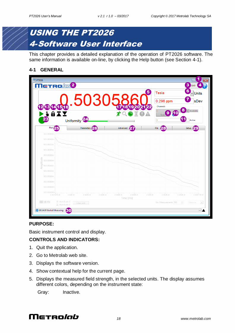
4-1 GENERAL
PURPOSE:
Basic instrument control and display.
CONTROLS AND INDICATORS:
1. Quit the application.
2. Go to Metrolab web site.
3. Displays the software version.
4. Show contextual help for the current page.
5. Displays the measured field strength, in the selected units. The display assumes different colors, depending on the instrument state:
Gray: Inactive.
PT2026 User’s Manual v 2.1 r 1.0 – 03/2017 Copyright © 2017 Metrolab Technology SA
19 www.metrolab.com
Orange: Searching for the NMR resonance. The value displayed is the Hall measurement, if available; otherwise, the last known NMR measurement.
Red: Measuring.
Black: Manual Search mode (see item 13). In this mode, the display becomes a control that dictates the field strength where the instrument searches for the NMR resonance. Type the value, in the selected units, or use the arrow keys to increment or decrement the digit to the left of the cursor.
6. Select the units in which to display the measurement results:
T: Tesla
mT: mTesla (1T=103 mT)
G: Gauss (1T=104 G)
kG: kGauss (1T=10 kG)
ppm: parts per million (relative to value set in Parameters > Display)
MHz: NMR frequency (depends on gyromagnetic ratio of sample material)
MHz-p: proton in water equivalent NMR frequency (1T ≈ 42.57638507 MHz-p)
7. Standard deviation of the measurement. Shown on the plot as error bars. Displays “NaN”, and no error bars, if Parameters > Search / Averaging > Measurement averaging is turned off.
8. The channel to be searched. A channel is either a physical probe, or a logical collection of probes, defined in Setup.
9. Force the PT2026 to scan for connected probes and update the channel list.
10. The currently active probe. For a physical channel, this is the same as the Channel selection, but for a logical collection of probes, this indicates which of those probes was used for the last measurement.
11. Probe information. Shows the currently active probe’s serial number and designation.
12. Start measuring. Click again to stop measuring.
13. Manual Search. Modify the Numeric Result field to set the search value (see item 5). Click this button again to reenter standard search mode; if the NMR value was found, it will be retained and the instrument will start measuring.
14. Freeze the Numeric Result display. The instrument, the Plot display and the file recording continue to function.
15. Retain the maximum measurement. The instrument, the Plot display and the file recording continue to function.
16. Retain the minimum measurement. The instrument, the Plot display and the file recording continue to function.
17. Indicates the instrument is running.
18. Indicates the instrument is searching for the NMR resonance.
19. Indicates the instrument is measuring.
20. Indicates the instrument is waiting for a trigger.
PT2026 User’s Manual v 2.1 r 1.0 – 03/2017 Copyright © 2017 Metrolab Technology SA
20 www.metrolab.com
21. Indicates that the instrument is unable to detect an NMR signal.
22. Indicates the measurement is not trustworthy. Lit in Manual Search mode because the NMR resonance might be above or below the set frequency.
23. Indicates the overall instrument status:
Green: Measuring; the displayed result is trustworthy.
Orange: Measurement is questionable, for example in Manual Search mode.
Red: Indicates that the instrument is unable to detect an NMR signal.
Yellow: Reviewing recorded data.
Off: Not measuring.
24. The Search progress bar shows the status of the NMR signal search; to be precise, it shows the current frequency within the selected range. Once the NMR signal has been found, the name of the progress bar changes to Uniformity, and indicates an estimate of the field uniformity.
25. Displays the Plot page, for graphical data displays.
26. Displays the Parameter page, for basic instrument adjustments.
27. Displays the Advanced page, for advanced instrument adjustments.
28. Displays the File page, for saving and recalling measurement files.
29. Displays the Setup page, for instrument configuration settings.
30. Provides prompts and status information. Click on the black arrow to expand it and see a log of past messages.
NOTES:
In Manual Search mode, the search value must be at least several kHz removed from the NMR resonant frequency for the mixer to produce an output. It is useful to display the NMR plot while adjusting the search value. When the NMR resonance is found manually, the Status Light turns orange.
PT2026 User’s Manual v 2.1 r 1.0 – 03/2017 Copyright © 2017 Metrolab Technology SA
21 www.metrolab.com
4-2 PLOT DISPLAY
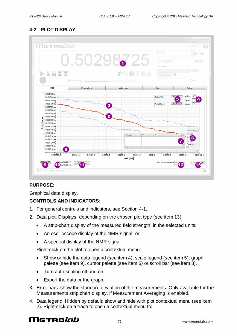
PURPOSE:
Graphical data display.
CONTROLS AND INDICATORS:
1. For general controls and indicators, see Section 4-1.
2. Data plot. Displays, depending on the chosen plot type (see item 13):
A strip-chart display of the measured field strength, in the selected units;
An oscilloscope display of the NMR signal; or
A spectral display of the NMR signal.
Right-click on the plot to open a contextual menu:
Show or hide the data legend (see item 4), scale legend (see item 5), graph palette (see item 9), cursor palette (see item 6) or scroll bar (see item 8).
Turn auto-scaling off and on.
Export the data or the graph.
3. Error bars: show the standard deviation of the measurements. Only available for the Measurements strip chart display, if Measurement Averaging is enabled.
4. Data legend. Hidden by default; show and hide with plot contextual menu (see item 2). Right-click on a trace to open a contextual menu to:

PT2026 User’s Manual v 2.1 r 1.0 – 03/2017 Copyright © 2017 Metrolab Technology SA
22 www.metrolab.com
Make the data trace visible or invisible.
Change the appearance of the data trace.
Export the data.
5. Scale legend. Hidden by default; show and hide with plot contextual menu (see item 2).
Change the axis labels.
Turn auto-scaling on or off.
Auto-scale once, if auto-scaling is off.
Change the format, precision and representation of the scale; show or hide the scale and axis labels; and change the grid color.
6. Match/Tune adjustment. Hidden by default; show and hide with the Advanced > Match / Tune screen.
7. Cursor palette. Hidden by default; show and hide with plot contextual menu (see item 2).
Create multiple cursors, either free or attached to a data trace.
Display the cursor values.
Change cursor attributes such as color.
8. Scroll horizontally if zoomed. Hidden by default, show with the plot contextual menu (see item 2).
9. Graph Palette. The graph palette tools manipulate the plot:
The Cursor tool moves the cursors created on the cursor palette (see item 6).
The Zoom tool zooms horizontally, vertically or both.
The Hand tool pans the graph, once zoomed.
10. Turns horizontal and vertical auto-scaling on and off. When manual scaling is selected, the scale can be modified by double-clicking and editing the minimum and maximum values.
11. Clear the plot and reset the scale.
12. The maximum number of measurements on the strip chart display.
13. Select the data to be plotted:
Measure: Plot the field measurements in strip-chart format.
NMR: Plot the NMR signal.
FFT: Plot the spectrum of the NMR signal.
NOTES:
PT2026 User’s Manual v 2.1 r 1.0 – 03/2017 Copyright © 2017 Metrolab Technology SA
23 www.metrolab.com
4-3 PARAMETERS > SEARCH & AVERAGING
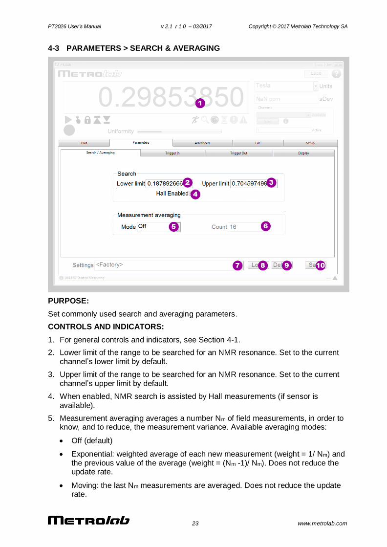
PURPOSE:
Set commonly used search and averaging parameters.
CONTROLS AND INDICATORS:
1. For general controls and indicators, see Section 4-1.
2. Lower limit of the range to be searched for an NMR resonance. Set to the current channel’s lower limit by default.
3. Upper limit of the range to be searched for an NMR resonance. Set to the current channel’s upper limit by default.
4. When enabled, NMR search is assisted by Hall measurements (if sensor is available).
5. Measurement averaging averages a number Nm of field measurements, in order to know, and to reduce, the measurement variance. Available averaging modes:
Off (default)
Exponential: weighted average of each new measurement (weight = 1/ Nm) and the previous value of the average (weight = (Nm -1)/ Nm). Does not reduce the update rate.
Moving: the last Nm measurements are averaged. Does not reduce the update rate.

PT2026 User’s Manual v 2.1 r 1.0 – 03/2017 Copyright © 2017 Metrolab Technology SA
24 www.metrolab.com
Block: successive blocks of Nm measurements are averaged. Reduces the update rate by a factor of Nm.
6. Measurement averaging count, Nm.
7. Pull-down list of settings saved in the instrument’s nonvolatile memory. The following names are predefined:
LastPowerOff.xml: automatically saved when the instrument is powered off.
<Factory>: factory default settings.
8. Load the selected settings. Note that loading certain settings requires rebooting the PT2026, which will break the connection to the instrument.
9. Delete the selected settings. The factory default settings cannot be deleted.
10. Save the current instrument settings under a user-defined name. Either all settings, or only a certain category of settings, can be saved:
All: all instrument settings.
Communication: computer interface settings.
Measure: search and measurement settings.
Trigger: trigger in and trigger out settings.
Reference Clock: reference clock settings.
Units: selected units and ppm reference value.
NOTES:
Some settings (for example communications settings) will cause the instrument to reboot, causing the connection to be lost.
PT2026 User’s Manual v 2.1 r 1.0 – 03/2017 Copyright © 2017 Metrolab Technology SA
25 www.metrolab.com
4-4 PARAMETERS > TRIGGER IN
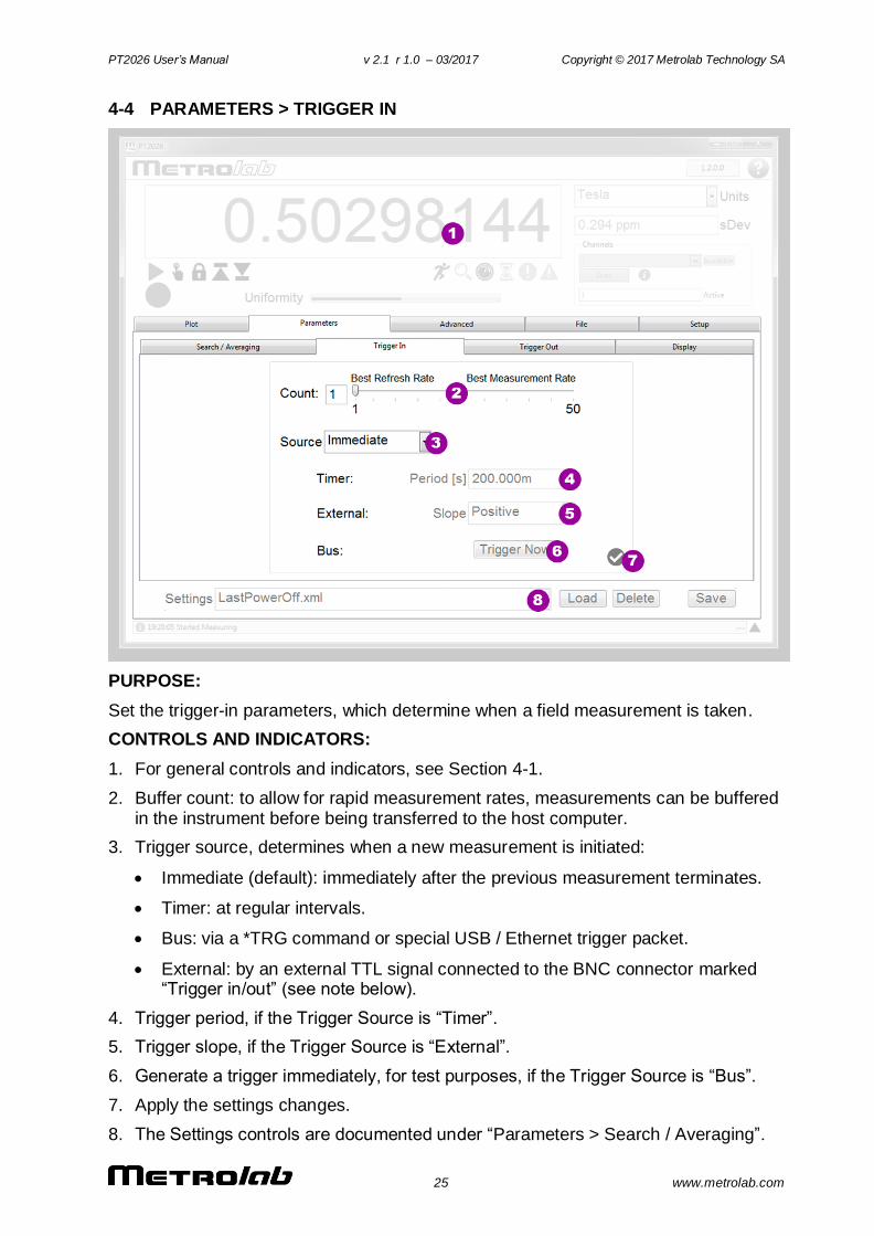
PURPOSE:
Set the trigger-in parameters, which determine when a field measurement is taken.
CONTROLS AND INDICATORS:
1. For general controls and indicators, see Section 4-1.
2. Buffer count: to allow for rapid measurement rates, measurements can be buffered in the instrument before being transferred to the host computer.
3. Trigger source, determines when a new measurement is initiated:
Immediate (default): immediately after the previous measurement terminates.
Timer: at regular intervals.
Bus: via a *TRG command or special USB / Ethernet trigger packet.
External: by an external TTL signal connected to the BNC connector marked “Trigger in/out” (see note below).
4. Trigger period, if the Trigger Source is “Timer”.
5. Trigger slope, if the Trigger Source is “External”.
6. Generate a trigger immediately, for test purposes, if the Trigger Source is “Bus”.
7. Apply the settings changes.
8. The Settings controls are documented under “Parameters > Search / Averaging”.
PT2026 User’s Manual v 2.1 r 1.0 – 03/2017 Copyright © 2017 Metrolab Technology SA
26 www.metrolab.com
NOTES:
The “Trigger in/out” BNC connector is either a trigger-in or a trigger-out. Consequently, the Trigger In Source can be set to “External” only if the Trigger Out Mode is “Off”.
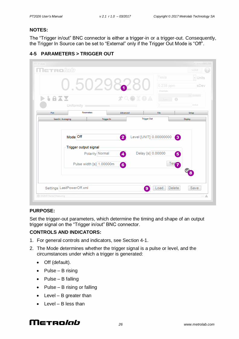
4-5 PARAMETERS > TRIGGER OUT
PURPOSE:
Set the trigger-out parameters, which determine the timing and shape of an output trigger signal on the “Trigger in/out” BNC connector.
CONTROLS AND INDICATORS:
1. For general controls and indicators, see Section 4-1.
2. The Mode determines whether the trigger signal is a pulse or level, and the circumstances under which a trigger is generated:
Off (default).
Pulse – B rising
Pulse – B falling
Pulse – B rising or falling
Level – B greater than
Level – B less than
PT2026 User’s Manual v 2.1 r 1.0 – 03/2017 Copyright © 2017 Metrolab Technology SA
27 www.metrolab.com
3. Field strength threshold, in the selected units.
4. With normal polarity, the trigger signal is a positive-going pulse or positive level. With inverted polarity, the trigger signal is a negative-going pulse or zero level.
5. Hold-off delay: time between the detection of the trigger condition and the generation of the trigger signal.
6. Pulse width, for a pulse trigger.
7. Generate a trigger signal in the selected configuration, for testing.
8. Apply the settings changes.
9. The Settings controls are documented under “Parameters > Search / Averaging”.
NOTES:
The “Trigger in/out” BNC connector is either a trigger-in or a trigger-out. Consequently, the Trigger Out Mode can only be “Off” if the Trigger In Source is set to “External.”
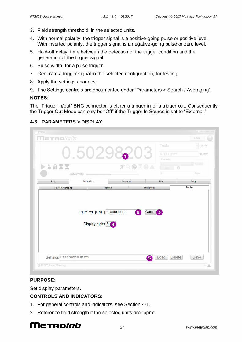
4-6 PARAMETERS > DISPLAY
PURPOSE:
Set display parameters.
CONTROLS AND INDICATORS:
1. For general controls and indicators, see Section 4-1.
2. Reference field strength if the selected units are “ppm”.
PT2026 User’s Manual v 2.1 r 1.0 – 03/2017 Copyright © 2017 Metrolab Technology SA
28 www.metrolab.com
3. Set the reference field strength to the currently measured value.
4. Set the number of digits of precision (i.e. number of digits behind the decimal point) for the numeric measurement display.
5. The Settings controls are documented under “Parameters > Search / Averaging”.
NOTES:
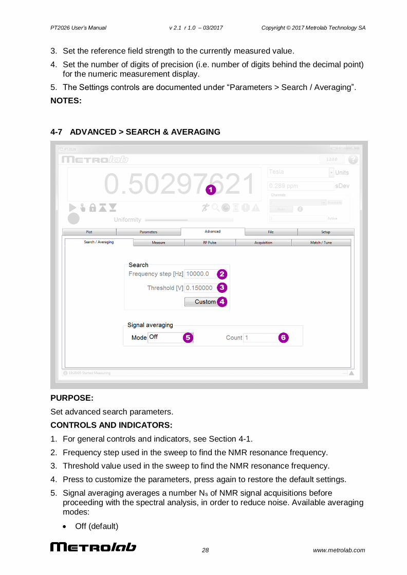
4-7 ADVANCED > SEARCH & AVERAGING
PURPOSE:
Set advanced search parameters.
CONTROLS AND INDICATORS:
1. For general controls and indicators, see Section 4-1.
2. Frequency step used in the sweep to find the NMR resonance frequency.
3. Threshold value used in the sweep to find the NMR resonance frequency.
4. Press to customize the parameters, press again to restore the default settings.
5. Signal averaging averages a number Ns of NMR signal acquisitions before proceeding with the spectral analysis, in order to reduce noise. Available averaging modes:
Off (default)
PT2026 User’s Manual v 2.1 r 1.0 – 03/2017 Copyright © 2017 Metrolab Technology SA
29 www.metrolab.com
Exponential: weighted average of each new NMR signal (weight = 1/ Ns) and the previous value of the average (weight = (Ns-1)/Ns). Does not reduce the update rate.
Block: successive blocks of Ns NMR signals are averaged. Reduces the update rate by a factor of Ns.
6. Signal averaging count, Ns.
NOTES:
The Advanced settings may cause the instrument to not measure. Restore the Factory defaults if necessary.
Averaging NMR signals can lead to strange behavior, especially if the magnetic field is not perfectly stable.
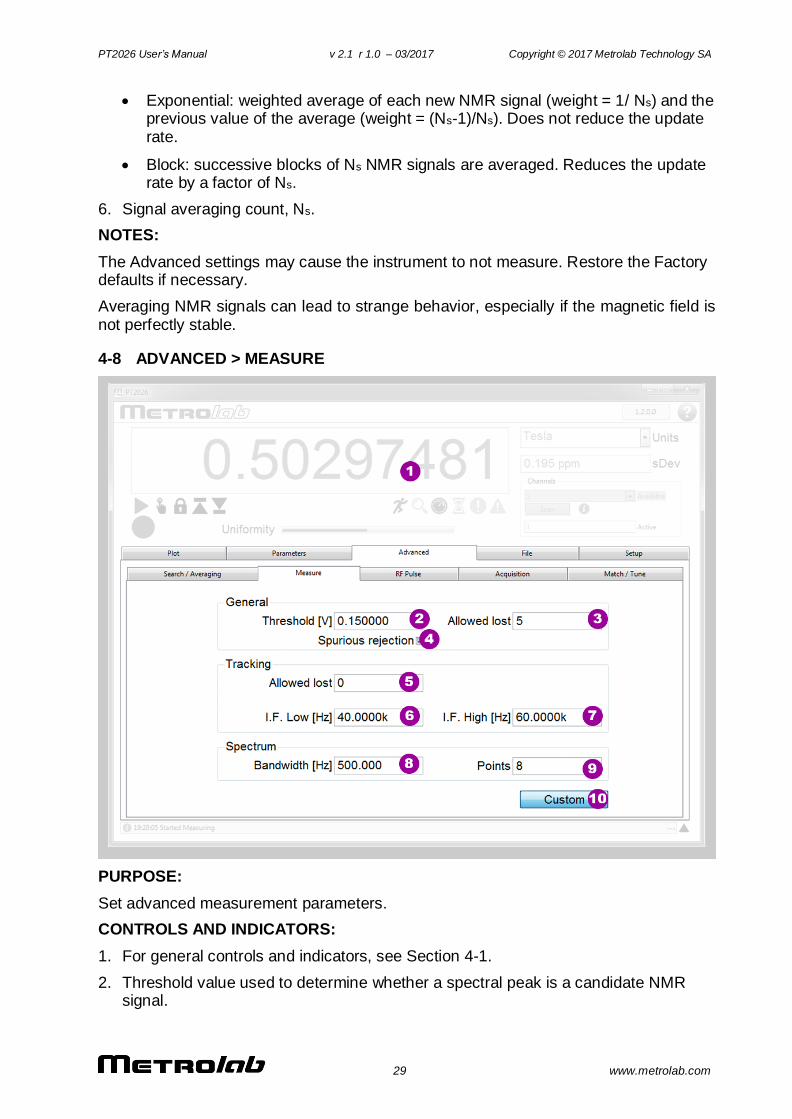
4-8 ADVANCED > MEASURE
PURPOSE:
Set advanced measurement parameters.
CONTROLS AND INDICATORS:
1. For general controls and indicators, see Section 4-1.
2. Threshold value used to determine whether a spectral peak is a candidate NMR signal.
PT2026 User’s Manual v 2.1 r 1.0 – 03/2017 Copyright © 2017 Metrolab Technology SA
30 www.metrolab.com
3. The number of failed measurements that are allowed before the instrument gives up and starts searching for the NMR resonance again.
4. Whether or not to test for, and reject, spurious signals that might be mistaken for an NMR resonance signal.
5. The number of measurements allowed outside the Intermediate Frequency tracking window before the RF frequency is adjusted.
6. The lower limit of the Intermediate Frequency tracking window.
7. The upper limit of the Intermediate Frequency tracking window.
8. The bandwidth over which the detailed spectral analysis is performed.
9. The number of points computed during the detailed spectral analysis.
10. Press to customize the parameters, press again to restore the default settings.
NOTES:
The Advanced settings may cause the instrument to not measure. Restore the Factory defaults if necessary.
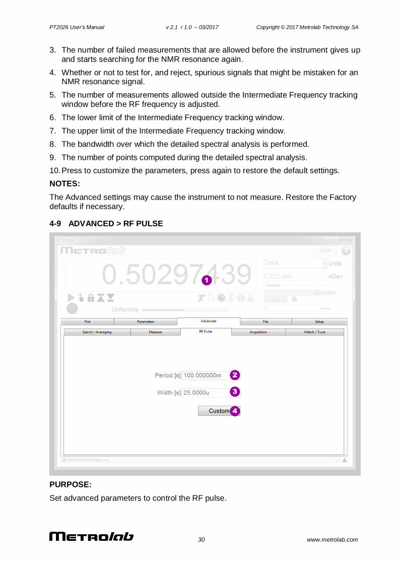
4-9 ADVANCED > RF PULSE
PURPOSE:
Set advanced parameters to control the RF pulse.
PT2026 User’s Manual v 2.1 r 1.0 – 03/2017 Copyright © 2017 Metrolab Technology SA
31 www.metrolab.com
CONTROLS AND INDICATORS:
1. For general controls and indicators, see Section 4-1.
2. The period of the Radio Frequency pulse.
3. The width of the Radio Frequency pulse.
4. Press to customize the parameters, press again to restore the default settings.
NOTES:
The Advanced settings may cause the instrument to not measure. Restore the Factory defaults if necessary.
The pulse period determines the measurement rate. Selecting too small a period relative to the NMR sample’s relaxation time will reduce the NMR signal amplitude (c.f. Ernst angle).
The pulse width determines the bandwidth of the pulse: a wide pulse will have a narrow bandwidth, and may require a reduced search frequency step (see Search & Averaging parameters).
The pulse width also determines the angle through which the spins are rotated (the “nutation” angle); a pulse that is too narrow or too wide will reduce the NMR signal amplitude (c.f. Ernst angle).
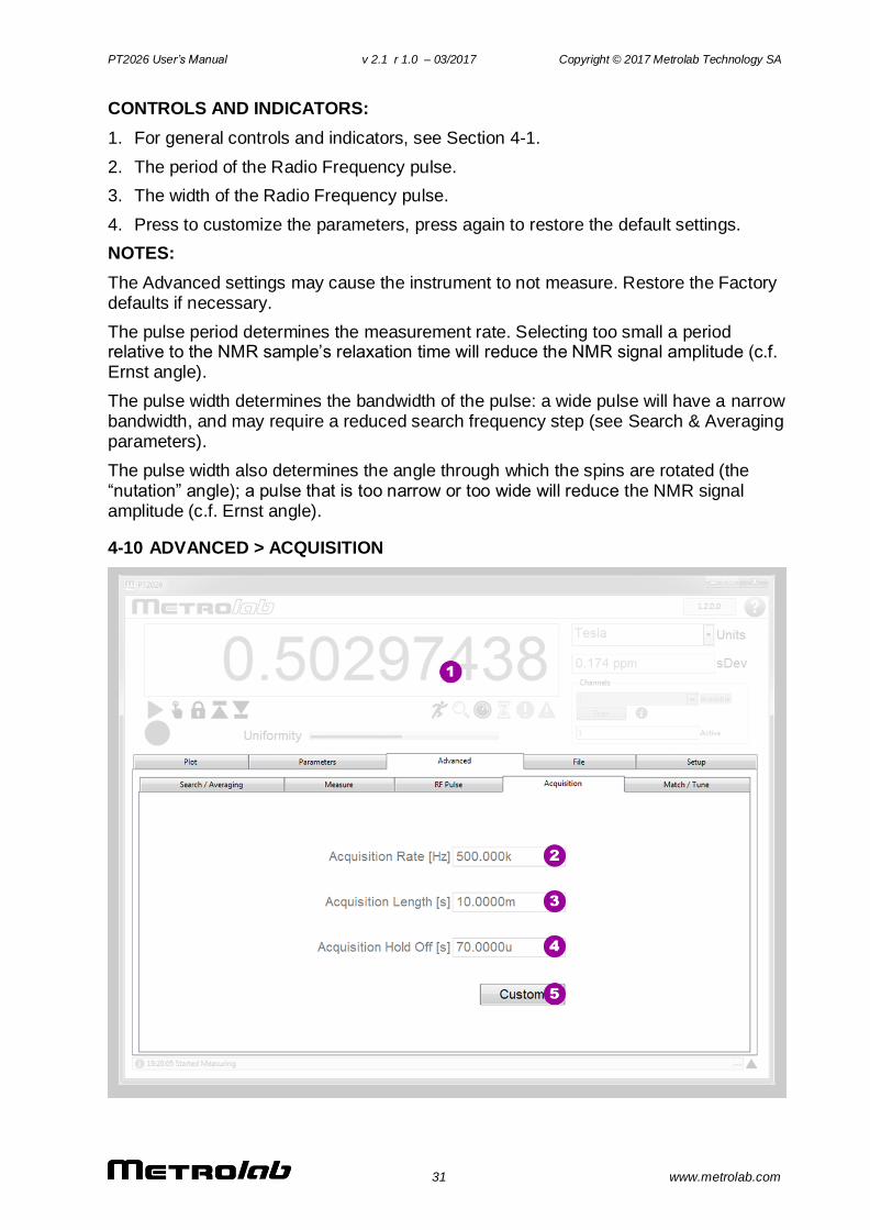
4-10 ADVANCED > ACQUISITION
PT2026 User’s Manual v 2.1 r 1.0 – 03/2017 Copyright © 2017 Metrolab Technology SA
32 www.metrolab.com
PURPOSE:
Set advanced digitization parameters.
CONTROLS AND INDICATORS:
1. For general controls and indicators, see Section 4-1.
2. The sample rate of the analog-to-digital conversion.
3. The length of the digitized NMR signal.
4. The dead time at the beginning of the acquisition, to avoid acquiring switching noise.
5. Press to customize the parameters, press again to restore the default settings.
NOTES:
The Advanced settings may cause the instrument to not measure. Restore the Factory defaults if necessary.
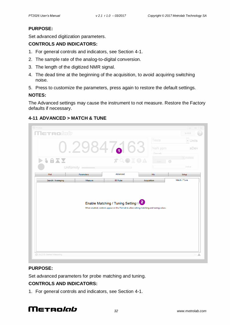
4-11 ADVANCED > MATCH & TUNE
PURPOSE:
Set advanced parameters for probe matching and tuning.
CONTROLS AND INDICATORS:
1. For general controls and indicators, see Section 4-1.
PT2026 User’s Manual v 2.1 r 1.0 – 03/2017 Copyright © 2017 Metrolab Technology SA
33 www.metrolab.com
2. When enabled, controls appear on the Plot screen to allow adjusting the matching and tuning voltages for the current probe.
NOTES:
The Advanced settings may cause the instrument to not measure. Restore the Factory defaults if necessary.
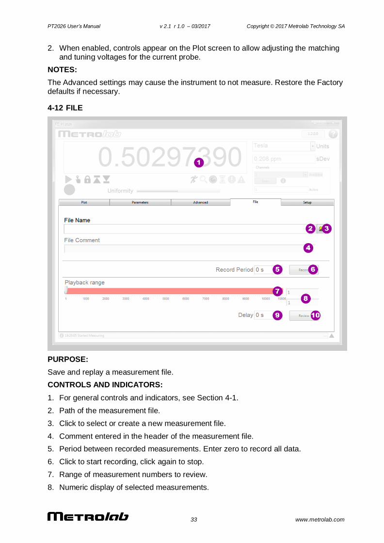
4-12 FILE
PURPOSE:
Save and replay a measurement file.
CONTROLS AND INDICATORS:
1. For general controls and indicators, see Section 4-1.
2. Path of the measurement file.
3. Click to select or create a new measurement file.
4. Comment entered in the header of the measurement file.
5. Period between recorded measurements. Enter zero to record all data.
6. Click to start recording, click again to stop.
7. Range of measurement numbers to review.
8. Numeric display of selected measurements.
PT2026 User’s Manual v 2.1 r 1.0 – 03/2017 Copyright © 2017 Metrolab Technology SA
34 www.metrolab.com
9. Update delay for reviewing measurements.
10. Click to start review, click again to stop.
NOTES:
The measurement file is a self-documenting human-readable text file, using the XML (Extensible Markup Language) format. It consists of a header section and a body section; the body section, in turn, is decomposed into a series of datasets, each with a table of measurement data, column headings, and associated instrument settings.
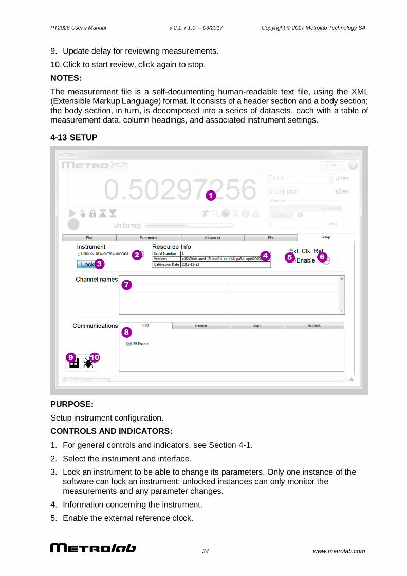
4-13 SETUP
PURPOSE:
Setup instrument configuration.
CONTROLS AND INDICATORS:
1. For general controls and indicators, see Section 4-1.
2. Select the instrument and interface.
3. Lock an instrument to be able to change its parameters. Only one instance of the software can lock an instrument; unlocked instances can only monitor the measurements and any parameter changes.
4. Information concerning the instrument.
5. Enable the external reference clock.
PT2026 User’s Manual v 2.1 r 1.0 – 03/2017 Copyright © 2017 Metrolab Technology SA
35 www.metrolab.com
6. Signals that an external reference clock is connected to the “10 MHz in/out” BNC connector.
7. Give a logical channel name to a list of one or more probes. Double-click on an empty line to add a definition, or double-click on an existing line to delete or modify it.
8. Enable or disable the different interfaces, and change parameters such as the IP addressing for Ethernet. Note that MODBUS is not yet supported.
9. Restore the factory defaults. This does the same thing as selecting the predefined “<Factory>” settings file. Note that loading factory settings require rebooting the PT2026, which will break the connection to the instrument.
10. Create a software debug log. The file is saved in the “Metrolab/PT2026/DebugLogs” subdirectory of the <User Application Data> directory. On Windows, the User Application Data path should be \Users\<User>\AppData\Local; on MacOS, /Users:<User>:Library:Application Support.
NOTES:
The syntax for defining channels is defined by the SCPI standard (Standard Commands for Programmable Instruments). Selecting a logical channel will search all its probes in order, and start measuring on the first one where an NMR resonance is found.
PT2026 User’s Manual v 2.1 r 1.0 – 03/2017 Copyright © 2017 Metrolab Technology SA
36 www.metrolab.com
PROGRAMMING THE PT2026
5- LabVIEW Instrument Driver
The LabVIEW Instrument Driver allows users to easily write instrument control
programs for the PT2026, using the LabVIEW® graphical programming
environment from National Instruments (www.ni.com).
The Instrument Driver is included in source code format (LabVIEW 2015 SP1) on
the CD that came with your PT2026. In the future, it will also be distributed on the
National Instruments Instrument Driver Network (www.ni.com/idnet). If upgrades
become available, you will be able to download them from the Metrolab website,
www.metrolab.com, or from the Instrument Driver Network.
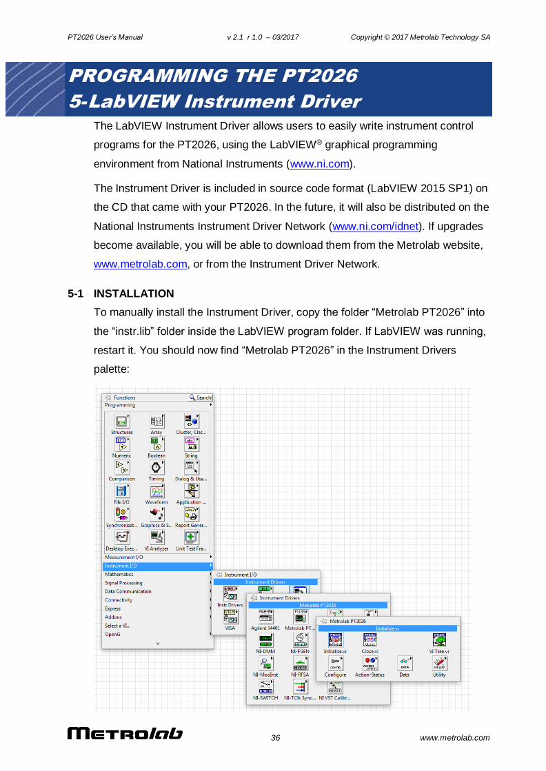
5-1 INSTALLATION
To manually install the Instrument Driver, copy the folder “Metrolab PT2026” into
the “instr.lib” folder inside the LabVIEW program folder. If LabVIEW was running,
restart it. You should now find “Metrolab PT2026” in the Instrument Drivers
palette:
PT2026 User’s Manual v 2.1 r 1.0 – 03/2017 Copyright © 2017 Metrolab Technology SA
37 www.metrolab.com
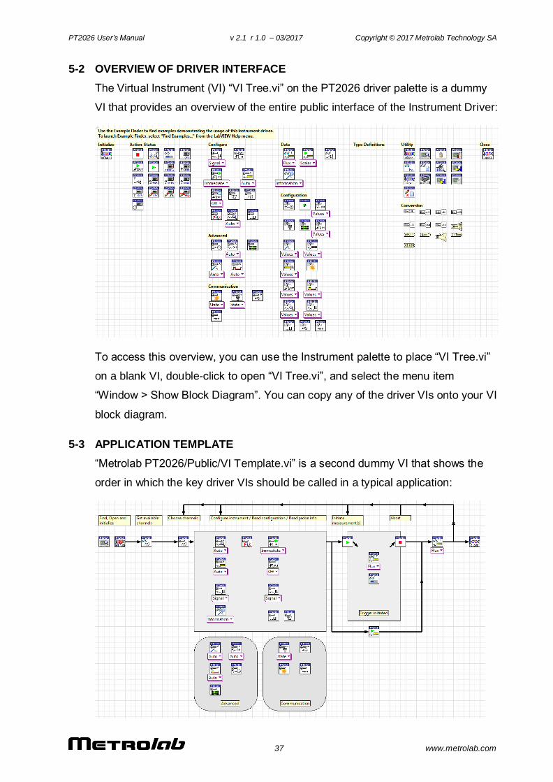
5-2 OVERVIEW OF DRIVER INTERFACE
The Virtual Instrument (VI) “VI Tree.vi” on the PT2026 driver palette is a dummy
VI that provides an overview of the entire public interface of the Instrument Driver:
To access this overview, you can use the Instrument palette to place “VI Tree.vi”
on a blank VI, double-click to open “VI Tree.vi”, and select the menu item
“Window > Show Block Diagram”. You can copy any of the driver VIs onto your VI
block diagram.
5-3 APPLICATION TEMPLATE
“Metrolab PT2026/Public/VI Template.vi” is a second dummy VI that shows the
order in which the key driver VIs should be called in a typical application:
PT2026 User’s Manual v 2.1 r 1.0 – 03/2017 Copyright © 2017 Metrolab Technology SA
38 www.metrolab.com
5-4 SAMPLE CODE
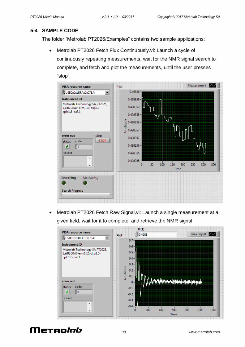
The folder “Metrolab PT2026/Examples” contains two sample applications:
Metrolab PT2026 Fetch Flux Continuously.vi: Launch a cycle of
continuously repeating measurements, wait for the NMR signal search to
complete, and fetch and plot the measurements, until the user presses
“stop”.
Metrolab PT2026 Fetch Raw Signal.vi: Launch a single measurement at a
given field, wait for it to complete, and retrieve the NMR signal.
PT2026 User’s Manual v 2.1 r 1.0 – 03/2017 Copyright © 2017 Metrolab Technology SA
39 www.metrolab.com
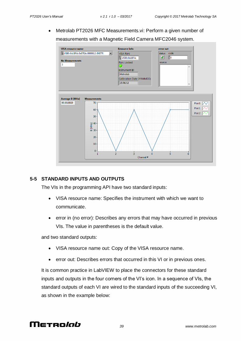
Metrolab PT2026 MFC Measurements.vi: Perform a given number of
measurements with a Magnetic Field Camera MFC2046 system.
5-5 STANDARD INPUTS AND OUTPUTS
The VIs in the programming API have two standard inputs:
VISA resource name: Specifies the instrument with which we want to
communicate.
error in (no error): Describes any errors that may have occurred in previous
VIs. The value in parentheses is the default value.
and two standard outputs:
VISA resource name out: Copy of the VISA resource name.
error out: Describes errors that occurred in this VI or in previous ones.
It is common practice in LabVIEW to place the connectors for these standard
inputs and outputs in the four corners of the VI’s icon. In a sequence of VIs, the
standard outputs of each VI are wired to the standard inputs of the succeeding VI,
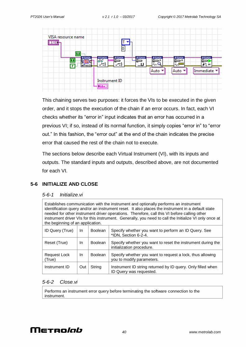
as shown in the example below:
PT2026 User’s Manual v 2.1 r 1.0 – 03/2017 Copyright © 2017 Metrolab Technology SA
40 www.metrolab.com
This chaining serves two purposes: it forces the VIs to be executed in the given
order, and it stops the execution of the chain if an error occurs. In fact, each VI
checks whether its “error in” input indicates that an error has occurred in a
previous VI; if so, instead of its normal function, it simply copies “error in” to “error
out.” In this fashion, the “error out” at the end of the chain indicates the precise
error that caused the rest of the chain not to execute.
The sections below describe each Virtual Instrument (VI), with its inputs and
outputs. The standard inputs and outputs, described above, are not documented
for each VI.
5-6 INITIALIZE AND CLOSE
5-6-1 Initialize.vi
Establishes communication with the instrument and optionally performs an instrument identification query and/or an instrument reset. It also places the instrument in a default state
needed for other instrument driver operations. Therefore, call this VI before calling other instrument driver VIs for this instrument. Generally, you need to call the Initialize VI only once at
the beginning of an application.
ID Query (True) In Boolean Specify whether you want to perform an ID Query. See *IDN, Section 6-2-4.
Reset (True) In Boolean Specify whether you want to reset the instrument during the initialization procedure.
Request Lock (True)
In Boolean Specify whether you want to request a lock, thus allowing you to modify parameters.
Instrument ID Out String Instrument ID string returned by ID query. Only filled when ID Query was requested.
5-6-2 Close.vi
Performs an instrument error query before terminating the software connection to the instrument.
PT2026 User’s Manual v 2.1 r 1.0 – 03/2017 Copyright © 2017 Metrolab Technology SA
41 www.metrolab.com
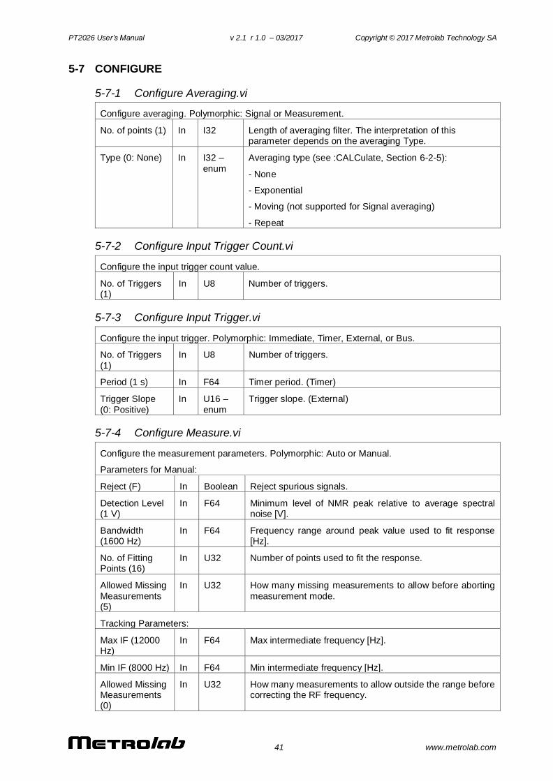
5-7 CONFIGURE
5-7-1 Configure Averaging.vi
Configure averaging. Polymorphic: Signal or Measurement.
No. of points (1) In I32 Length of averaging filter. The interpretation of this parameter depends on the averaging Type.
Type (0: None) In I32 –
enum
Averaging type (see :CALCulate, Section 6-2-5):
- None
- Exponential
- Moving (not supported for Signal averaging)
- Repeat
5-7-2 Configure Input Trigger Count.vi
Configure the input trigger count value.
No. of Triggers (1)
In U8 Number of triggers.
5-7-3 Configure Input Trigger.vi
Configure the input trigger. Polymorphic: Immediate, Timer, External, or Bus.
No. of Triggers
(1)
In U8 Number of triggers.
Period (1 s) In F64 Timer period. (Timer)
Trigger Slope
(0: Positive)
In U16 –
enum
Trigger slope. (External)
5-7-4 Configure Measure.vi
Configure the measurement parameters. Polymorphic: Auto or Manual.
Parameters for Manual:
Reject (F) In Boolean Reject spurious signals.
Detection Level (1 V)
In F64 Minimum level of NMR peak relative to average spectral noise [V].
Bandwidth (1600 Hz)
In F64 Frequency range around peak value used to fit response [Hz].
No. of Fitting Points (16)
In U32 Number of points used to fit the response.
Allowed Missing
Measurements (5)
In U32 How many missing measurements to allow before aborting
measurement mode.
Tracking Parameters:
Max IF (12000 Hz)
In F64 Max intermediate frequency [Hz].
Min IF (8000 Hz) In F64 Min intermediate frequency [Hz].
Allowed Missing Measurements (0)
In U32 How many measurements to allow outside the range before correcting the RF frequency.
PT2026 User’s Manual v 2.1 r 1.0 – 03/2017 Copyright © 2017 Metrolab Technology SA
42 www.metrolab.com
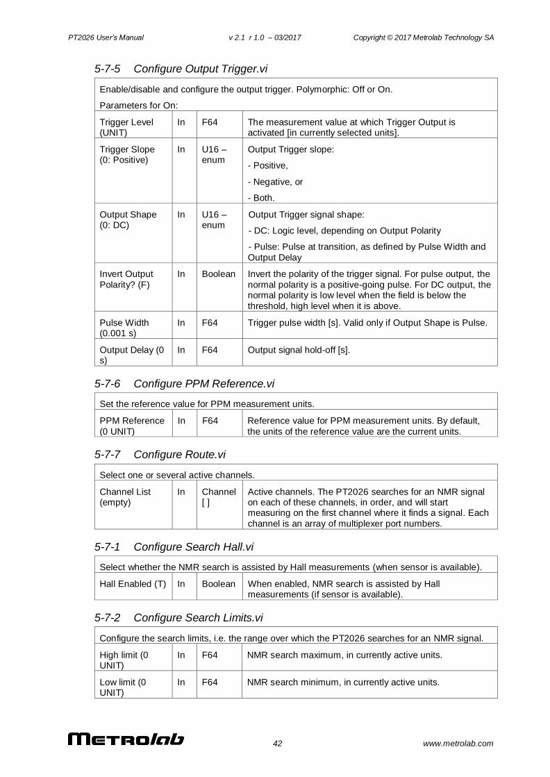
5-7-5 Configure Output Trigger.vi
Enable/disable and configure the output trigger. Polymorphic: Off or On.
Parameters for On:
Trigger Level (UNIT)
In F64 The measurement value at which Trigger Output is activated [in currently selected units].
Trigger Slope (0: Positive)
In U16 – enum
Output Trigger slope:
- Positive,
- Negative, or
- Both.
Output Shape (0: DC)
In U16 –enum
Output Trigger signal shape:
- DC: Logic level, depending on Output Polarity
- Pulse: Pulse at transition, as defined by Pulse Width and
Output Delay
Invert Output
Polarity? (F)
In Boolean Invert the polarity of the trigger signal. For pulse output, the
normal polarity is a positive-going pulse. For DC output, the normal polarity is low level when the field is below the
threshold, high level when it is above.
Pulse Width (0.001 s)
In F64 Trigger pulse width [s]. Valid only if Output Shape is Pulse.
Output Delay (0 s)
In F64 Output signal hold-off [s].
5-7-6 Configure PPM Reference.vi
Set the reference value for PPM measurement units.
PPM Reference
(0 UNIT)
In F64 Reference value for PPM measurement units. By default,
the units of the reference value are the current units.
5-7-7 Configure Route.vi
Select one or several active channels.
Channel List (empty)
In Channel [ ]
Active channels. The PT2026 searches for an NMR signal on each of these channels, in order, and will start measuring on the first channel where it finds a signal. Each
channel is an array of multiplexer port numbers.
5-7-1 Configure Search Hall.vi
Select whether the NMR search is assisted by Hall measurements (when sensor is available).
Hall Enabled (T) In Boolean When enabled, NMR search is assisted by Hall measurements (if sensor is available).
5-7-2 Configure Search Limits.vi
Configure the search limits, i.e. the range over which the PT2026 searches for an NMR signal.
High limit (0 UNIT)
In F64 NMR search maximum, in currently active units.
Low limit (0 UNIT)
In F64 NMR search minimum, in currently active units.
PT2026 User’s Manual v 2.1 r 1.0 – 03/2017 Copyright © 2017 Metrolab Technology SA
43 www.metrolab.com
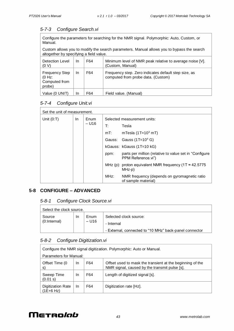
5-7-3 Configure Search.vi
Configure the parameters for searching for the NMR signal. Polymorphic: Auto, Custom, or Manual.
Custom allows you to modify the search parameters. Manual allows you to bypass the search
altogether by specifying a field value.
Detection Level (0 V)
In F64 Minimum level of NMR peak relative to average noise [V]. (Custom, Manual)
Frequency Step (0 Hz: Computed from
probe)
In F64 Frequency step. Zero indicates default step size, as computed from probe data. (Custom)
Value (0 UNIT) In F64 Field value. (Manual)
5-7-4 Configure Unit.vi
Set the unit of measurement.
Unit (0:T) In Enum – U16
Selected measurement units:
T: Tesla
mT: mTesla (1T=103 mT)
Gauss: Gauss (1T=104 G)
kGauss: kGauss (1T=10 kG)
ppm: parts per million (relative to value set in “Configure PPM Reference.vi”)
MHz (p): proton equivalent NMR frequency (1T ≈ 42.5775
MHz-p)
MHz: NMR frequency (depends on gyromagnetic ratio of sample material)
5-8 CONFIGURE – ADVANCED
5-8-1 Configure Clock Source.vi
Select the clock source.
Source
(0:Internal)
In Enum
– U16
Selected clock source:
- Internal
- External, connected to “10 MHz” back-panel connector
5-8-2 Configure Digitization.vi
Configure the NMR signal digitization. Polymorphic: Auto or Manual.
Parameters for Manual:
Offset Time (0
s)
In F64 Offset used to mask the transient at the beginning of the
NMR signal, caused by the transmit pulse [s].
Sweep Time (0.01 s)
In F64 Length of digitized signal [s].
Digitization Rate (1E+6 Hz)
In F64 Digitization rate [Hz].
PT2026 User’s Manual v 2.1 r 1.0 – 03/2017 Copyright © 2017 Metrolab Technology SA
44 www.metrolab.com
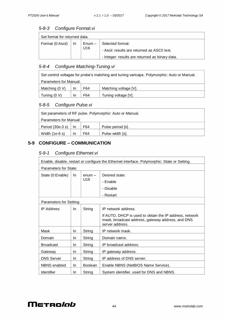
5-8-3 Configure Format.vi
Set format for returned data.
Format (0:Ascii) In Enum –
U16
Selected format:
- Ascii: results are returned as ASCII text.
- Integer: results are returned as binary data.
5-8-4 Configure Matching-Tuning.vi
Set control voltages for probe’s matching and tuning varicaps. Polymorphic: Auto or Manual.
Parameters for Manual:
Matching (0 V) In F64 Matching voltage [V].
Tuning (0 V) In F64 Tuning voltage [V].
5-8-5 Configure Pulse.vi
Set parameters of RF pulse. Polymorphic: Auto or Manual.
Parameters for Manual:
Period (30e-3 s) In F64 Pulse period [s].
Width (1e-6 s) In F64 Pulse width [s].
5-9 CONFIGURE – COMMUNICATION
5-9-1 Configure Ethernet.vi
Enable, disable, restart or configure the Ethernet interface. Polymorphic: State or Setting.
Parameters for State:
State (0:Enable) In enum – U16
Desired state:
- Enable
- Disable
- Restart
Parameters for Setting:
IP Address In String IP network address.
If AUTO, DHCP is used to obtain the IP address, network mask, broadcast address, gateway address, and DNS
server address.
Mask In String IP network mask.
Domain In String Domain name.
Broadcast In String IP broadcast address.
Gateway In String IP gateway address.
DNS Server In String IP address of DNS server.
NBNS enabled In Boolean Enable NBNS (NetBIOS Name Service).
Identifier In String System identifier, used for DNS and NBNS.
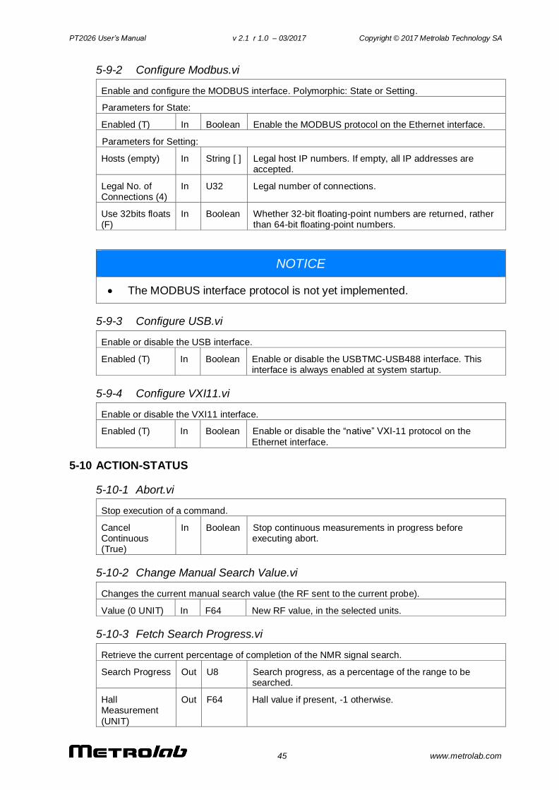
PT2026 User’s Manual v 2.1 r 1.0 – 03/2017 Copyright © 2017 Metrolab Technology SA
45 www.metrolab.com
5-9-2 Configure Modbus.vi
Enable and configure the MODBUS interface. Polymorphic: State or Setting.
Parameters for State:
Enabled (T) In Boolean Enable the MODBUS protocol on the Ethernet interface.
Parameters for Setting:
Hosts (empty) In String [ ] Legal host IP numbers. If empty, all IP addresses are accepted.
Legal No. of Connections (4)
In U32 Legal number of connections.
Use 32bits floats (F)
In Boolean Whether 32-bit floating-point numbers are returned, rather than 64-bit floating-point numbers.
NOTICE
The MODBUS interface protocol is not yet implemented.
5-9-3 Configure USB.vi
Enable or disable the USB interface.
Enabled (T) In Boolean Enable or disable the USBTMC-USB488 interface. This interface is always enabled at system startup.
5-9-4 Configure VXI11.vi
Enable or disable the VXI11 interface.
Enabled (T) In Boolean Enable or disable the “native” VXI-11 protocol on the
Ethernet interface.
5-10 ACTION-STATUS
5-10-1 Abort.vi
Stop execution of a command.
Cancel Continuous (True)
In Boolean Stop continuous measurements in progress before executing abort.
5-10-2 Change Manual Search Value.vi
Changes the current manual search value (the RF sent to the current probe).
Value (0 UNIT) In F64 New RF value, in the selected units.
5-10-3 Fetch Search Progress.vi
Retrieve the current percentage of completion of the NMR signal search.
Search Progress Out U8 Search progress, as a percentage of the range to be searched.
Hall Measurement
(UNIT)
Out F64 Hall value if present, -1 otherwise.
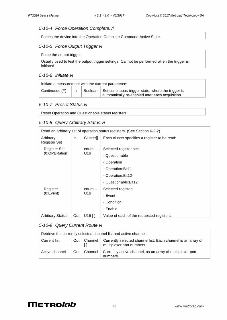
PT2026 User’s Manual v 2.1 r 1.0 – 03/2017 Copyright © 2017 Metrolab Technology SA
46 www.metrolab.com
5-10-4 Force Operation Complete.vi
Forces the device into the Operation Complete Command Active State.
5-10-5 Force Output Trigger.vi
Force the output trigger.
Usually used to test the output trigger settings. Cannot be performed when the trigger is
initiated.
5-10-6 Initiate.vi
Initiate a measurement with the current parameters.
Continuous (F) In Boolean Set continuous-trigger state, where the trigger is automatically re-enabled after each acquisition.
5-10-7 Preset Status.vi
Reset Operation and Questionable status registers.
5-10-8 Query Arbitrary Status.vi
Read an arbitrary set of operation status registers. (See Section 6-2-2)
Arbitrary Register Set
In Cluster[] Each cluster specifies a register to be read:
Register Set
(0:OPERation)
enum –
U16
Selected register set:
- Questionable
- Operation
- Operation:Bit11
- Operation:Bit12
- Questionable:Bit12
Register (0:Event)
enum – U16
Selected register:
- Event
- Condition
- Enable
Arbitrary Status Out U16 [ ] Value of each of the requested registers.
5-10-9 Query Current Route.vi
Retrieve the currently selected channel list and active channel.
Current list Out Channel
[ ]
Currently selected channel list. Each channel is an array of
multiplexer port numbers.
Active channel Out Channel Currently active channel, as an array of multiplexer port numbers.
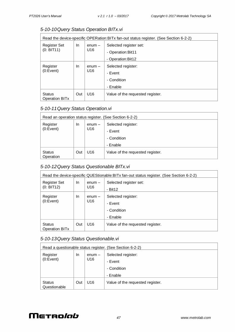
PT2026 User’s Manual v 2.1 r 1.0 – 03/2017 Copyright © 2017 Metrolab Technology SA
47 www.metrolab.com
5-10-10 Query Status Operation BITx.vi
Read the device-specific OPERation:BITx fan-out status register. (See Section 6-2-2)
Register Set
(0: BIT11)
In enum –
U16
Selected register set:
- Operation:Bit11
- Operation:Bit12
Register (0:Event)
In enum – U16
Selected register:
- Event
- Condition
- Enable
Status Operation BITx
Out U16 Value of the requested register.
5-10-11 Query Status Operation.vi
Read an operation status register. (See Section 6-2-2)
Register (0:Event)
In enum – U16
Selected register:
- Event
- Condition
- Enable
Status Operation
Out U16 Value of the requested register.
5-10-12 Query Status Questionable BITx.vi
Read the device-specific QUEStionable:BITx fan-out status register. (See Section 6-2-2)
Register Set
(0: BIT12)
In enum –
U16
Selected register set:
- Bit12
Register
(0:Event)
In enum –
U16
Selected register:
- Event
- Condition
- Enable
Status
Operation BITx
Out U16 Value of the requested register.
5-10-13 Query Status Questionable.vi
Read a questionable status register. (See Section 6-2-2)
Register (0:Event)
In enum – U16
Selected register:
- Event
- Condition
- Enable
Status
Questionable
Out U16 Value of the requested register.
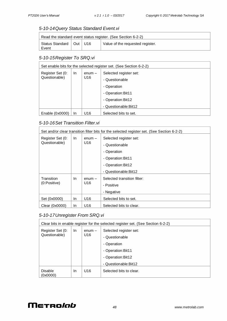
PT2026 User’s Manual v 2.1 r 1.0 – 03/2017 Copyright © 2017 Metrolab Technology SA
48 www.metrolab.com
5-10-14 Query Status Standard Event.vi
Read the standard event status register. (See Section 6-2-2)
Status Standard
Event
Out U16 Value of the requested register.
5-10-15 Register To SRQ.vi
Set enable bits for the selected register set. (See Section 6-2-2)
Register Set (0: Questionable)
In enum – U16
Selected register set:
- Questionable
- Operation
- Operation:Bit11
- Operation:Bit12
- Questionable:Bit12
Enable (0x0000) In U16 Selected bits to set.
5-10-16 Set Transition Filter.vi
Set and/or clear transition filter bits for the selected register set. (See Section 6-2-2)
Register Set (0:
Questionable)
In enum –
U16
Selected register set:
- Questionable
- Operation
- Operation:Bit11
- Operation:Bit12
- Questionable:Bit12
Transition (0:Positive)
In enum – U16
Selected transition filter:
- Positive
- Negative
Set (0x0000) In U16 Selected bits to set.
Clear (0x0000) In U16 Selected bits to clear.
5-10-17 Unregister From SRQ.vi
Clear bits in enable register for the selected register set. (See Section 6-2-2)
Register Set (0: Questionable)
In enum – U16
Selected register set:
- Questionable
- Operation
- Operation:Bit11
- Operation:Bit12
- Questionable:Bit12
Disable (0x0000)
In U16 Selected bits to clear.
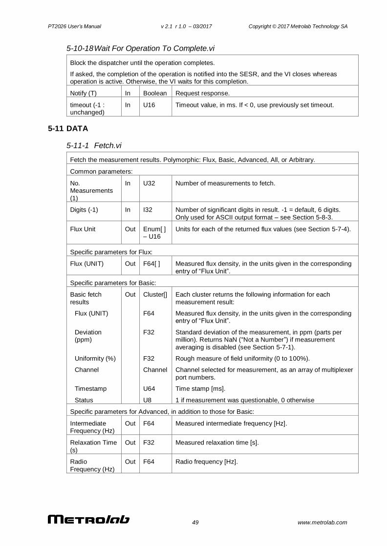
PT2026 User’s Manual v 2.1 r 1.0 – 03/2017 Copyright © 2017 Metrolab Technology SA
49 www.metrolab.com
5-10-18 Wait For Operation To Complete.vi
Block the dispatcher until the operation completes.
If asked, the completion of the operation is notified into the SESR, and the VI closes whereas operation is active. Otherwise, the VI waits for this completion.
Notify (T) In Boolean Request response.
timeout (-1 : unchanged)
In U16 Timeout value, in ms. If < 0, use previously set timeout.
5-11 DATA
5-11-1 Fetch.vi
Fetch the measurement results. Polymorphic: Flux, Basic, Advanced, All, or Arbitrary.
Common parameters:
No. Measurements
(1)
In U32 Number of measurements to fetch.
Digits (-1) In I32 Number of significant digits in result. -1 = default, 6 digits.
Only used for ASCII output format – see Section 5-8-3.
Flux Unit Out Enum[ ] – U16
Units for each of the returned flux values (see Section 5-7-4).
Specific parameters for Flux:
Flux (UNIT) Out F64[ ] Measured flux density, in the units given in the corresponding
entry of “Flux Unit”.
Specific parameters for Basic:
Basic fetch
results
Out Cluster[] Each cluster returns the following information for each
measurement result:
Flux (UNIT) F64 Measured flux density, in the units given in the corresponding entry of “Flux Unit”.
Deviation (ppm)
F32 Standard deviation of the measurement, in ppm (parts per million). Returns NaN (“Not a Number”) if measurement
averaging is disabled (see Section 5-7-1).
Uniformity (%) F32 Rough measure of field uniformity (0 to 100%).
Channel Channel Channel selected for measurement, as an array of multiplexer
port numbers.
Timestamp U64 Time stamp [ms].
Status U8 1 if measurement was questionable, 0 otherwise
Specific parameters for Advanced, in addition to those for Basic:
Intermediate Frequency (Hz)
Out F64 Measured intermediate frequency [Hz].
Relaxation Time
(s)
Out F32 Measured relaxation time [s].
Radio
Frequency (Hz)
Out F64 Radio frequency [Hz].
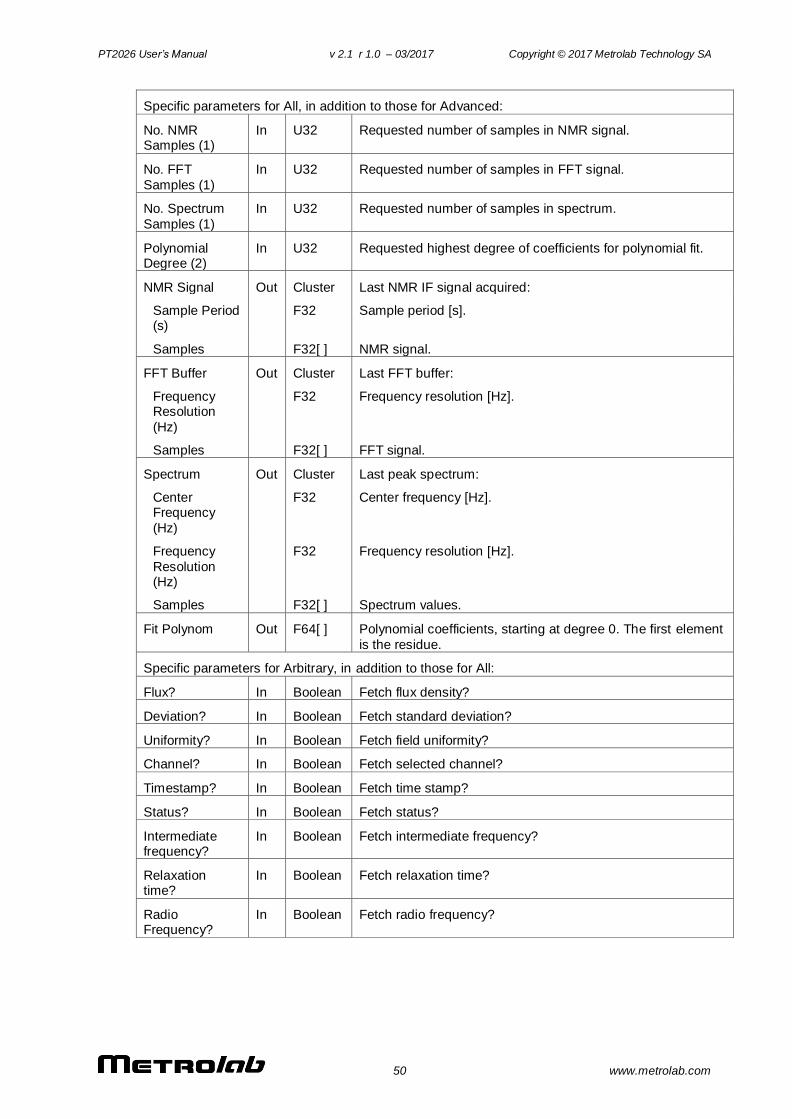
PT2026 User’s Manual v 2.1 r 1.0 – 03/2017 Copyright © 2017 Metrolab Technology SA
50 www.metrolab.com
Specific parameters for All, in addition to those for Advanced:
No. NMR Samples (1)
In U32 Requested number of samples in NMR signal.
No. FFT
Samples (1)
In U32 Requested number of samples in FFT signal.
No. Spectrum
Samples (1)
In U32 Requested number of samples in spectrum.
Polynomial Degree (2)
In U32 Requested highest degree of coefficients for polynomial fit.
NMR Signal Out Cluster Last NMR IF signal acquired:
Sample Period (s)
F32 Sample period [s].
Samples F32[ ] NMR signal.
FFT Buffer Out Cluster Last FFT buffer:
Frequency Resolution
(Hz)
F32 Frequency resolution [Hz].
Samples F32[ ] FFT signal.
Spectrum Out Cluster Last peak spectrum:
Center Frequency
(Hz)
F32 Center frequency [Hz].
Frequency
Resolution (Hz)
F32 Frequency resolution [Hz].
Samples F32[ ] Spectrum values.
Fit Polynom Out F64[ ] Polynomial coefficients, starting at degree 0. The first element
is the residue.
Specific parameters for Arbitrary, in addition to those for All:
Flux? In Boolean Fetch flux density?
Deviation? In Boolean Fetch standard deviation?
Uniformity? In Boolean Fetch field uniformity?
Channel? In Boolean Fetch selected channel?
Timestamp? In Boolean Fetch time stamp?
Status? In Boolean Fetch status?
Intermediate frequency?
In Boolean Fetch intermediate frequency?
Relaxation time?
In Boolean Fetch relaxation time?
Radio Frequency?
In Boolean Fetch radio frequency?
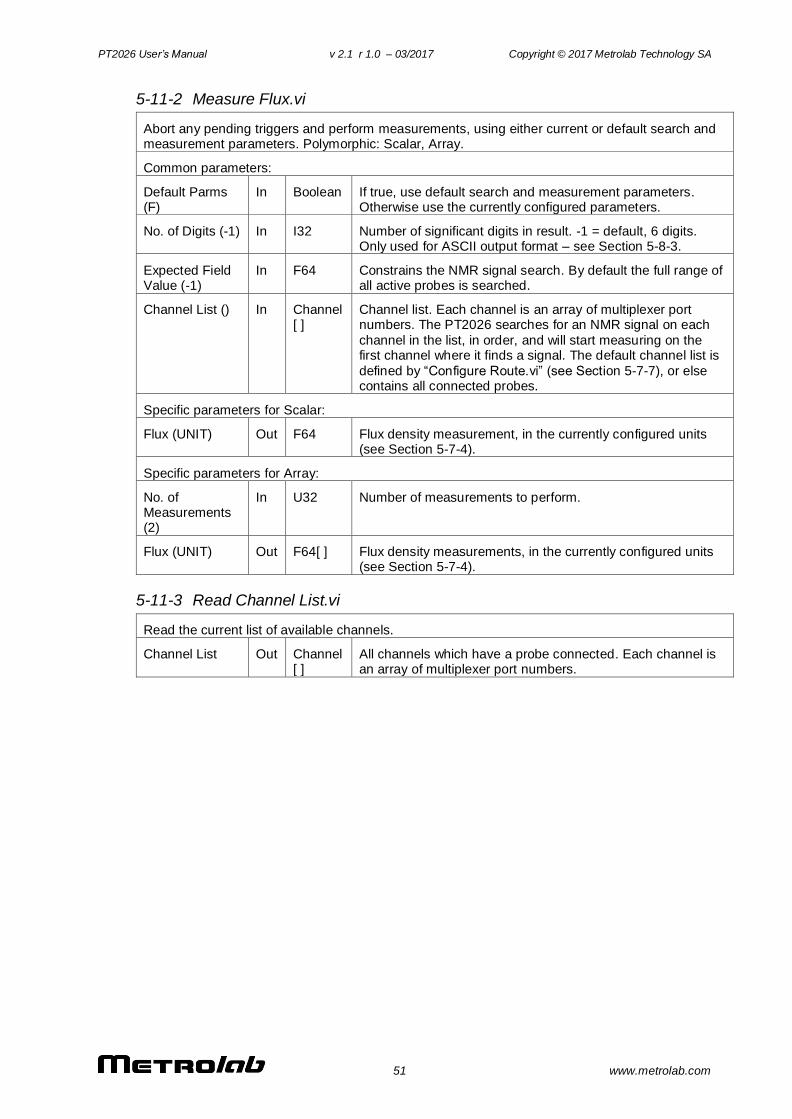
PT2026 User’s Manual v 2.1 r 1.0 – 03/2017 Copyright © 2017 Metrolab Technology SA
51 www.metrolab.com
5-11-2 Measure Flux.vi
Abort any pending triggers and perform measurements, using either current or default search and measurement parameters. Polymorphic: Scalar, Array.
Common parameters:
Default Parms (F)
In Boolean If true, use default search and measurement parameters. Otherwise use the currently configured parameters.
No. of Digits (-1) In I32 Number of significant digits in result. -1 = default, 6 digits. Only used for ASCII output format – see Section 5-8-3.
Expected Field Value (-1)
In F64 Constrains the NMR signal search. By default the full range of all active probes is searched.
Channel List () In Channel [ ]
Channel list. Each channel is an array of multiplexer port numbers. The PT2026 searches for an NMR signal on each
channel in the list, in order, and will start measuring on the first channel where it finds a signal. The default channel list is
defined by “Configure Route.vi” (see Section 5-7-7), or else contains all connected probes.
Specific parameters for Scalar:
Flux (UNIT) Out F64 Flux density measurement, in the currently configured units (see Section 5-7-4).
Specific parameters for Array:
No. of Measurements (2)
In U32 Number of measurements to perform.
Flux (UNIT) Out F64[ ] Flux density measurements, in the currently configured units (see Section 5-7-4).
5-11-3 Read Channel List.vi
Read the current list of available channels.
Channel List Out Channel[ ]
All channels which have a probe connected. Each channel is an array of multiplexer port numbers.
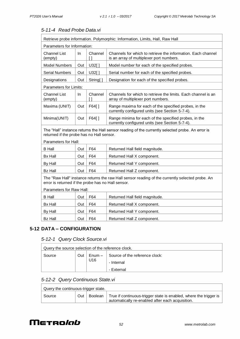
PT2026 User’s Manual v 2.1 r 1.0 – 03/2017 Copyright © 2017 Metrolab Technology SA
52 www.metrolab.com
5-11-4 Read Probe Data.vi
Retrieve probe information. Polymorphic: Information, Limits, Hall, Raw Hall
Parameters for Information:
Channel List (empty)
In Channel[ ]
Channels for which to retrieve the information. Each channel is an array of multiplexer port numbers.
Model Numbers Out U32[ ] Model number for each of the specified probes.
Serial Numbers Out U32[ ] Serial number for each of the specified probes.
Designations Out String[ ] Designation for each of the specified probes.
Parameters for Limits:
Channel List
(empty)
In Channel
[ ]
Channels for which to retrieve the limits. Each channel is an
array of multiplexer port numbers.
Maxima (UNIT) Out F64[ ] Range maxima for each of the specified probes, in the
currently configured units (see Section 5-7-4).
Minima(UNIT) Out F64[ ] Range minima for each of the specified probes, in the currently configured units (see Section 5-7-4).
The “Hall” instance returns the Hall sensor reading of the currently selected probe. An error is returned if the probe has no Hall sensor.
Parameters for Hall:
B Hall Out F64 Returned Hall field magnitude.
Bx Hall Out F64 Returned Hall X component.
By Hall Out F64 Returned Hall Y component.
Bz Hall Out F64 Returned Hall Z component.
The "Raw Hall" instance returns the raw Hall sensor reading of the currently selected probe. An
error is returned if the probe has no Hall sensor.
Parameters for Raw Hall:
B Hall Out F64 Returned Hall field magnitude.
Bx Hall Out F64 Returned Hall X component.
By Hall Out F64 Returned Hall Y component.
Bz Hall Out F64 Returned Hall Z component.
5-12 DATA – CONFIGURATION
5-12-1 Query Clock Source.vi
Query the source selection of the reference clock.
Source Out Enum – U16
Source of the reference clock:
- Internal
- External
5-12-2 Query Continuous State.vi
Query the continuous-trigger state.
Source Out Boolean True if continuous-trigger state is enabled, where the trigger is automatically re-enabled after each acquisition.
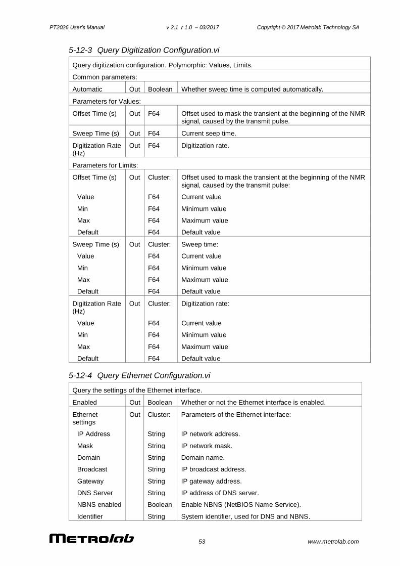
PT2026 User’s Manual v 2.1 r 1.0 – 03/2017 Copyright © 2017 Metrolab Technology SA
53 www.metrolab.com
5-12-3 Query Digitization Configuration.vi
Query digitization configuration. Polymorphic: Values, Limits.
Common parameters:
Automatic Out Boolean Whether sweep time is computed automatically.
Parameters for Values:
Offset Time (s) Out F64 Offset used to mask the transient at the beginning of the NMR signal, caused by the transmit pulse.
Sweep Time (s) Out F64 Current seep time.
Digitization Rate (Hz)
Out F64 Digitization rate.
Parameters for Limits:
Offset Time (s) Out Cluster: Offset used to mask the transient at the beginning of the NMR
signal, caused by the transmit pulse:
Value F64 Current value
Min F64 Minimum value
Max F64 Maximum value
Default F64 Default value
Sweep Time (s) Out Cluster: Sweep time:
Value F64 Current value
Min F64 Minimum value
Max F64 Maximum value
Default F64 Default value
Digitization Rate (Hz)
Out Cluster: Digitization rate:
Value F64 Current value
Min F64 Minimum value
Max F64 Maximum value
Default F64 Default value
5-12-4 Query Ethernet Configuration.vi
Query the settings of the Ethernet interface.
Enabled Out Boolean Whether or not the Ethernet interface is enabled.
Ethernet settings
Out Cluster: Parameters of the Ethernet interface:
IP Address String IP network address.
Mask String IP network mask.
Domain String Domain name.
Broadcast String IP broadcast address.
Gateway String IP gateway address.
DNS Server String IP address of DNS server.
NBNS enabled Boolean Enable NBNS (NetBIOS Name Service).
Identifier String System identifier, used for DNS and NBNS.
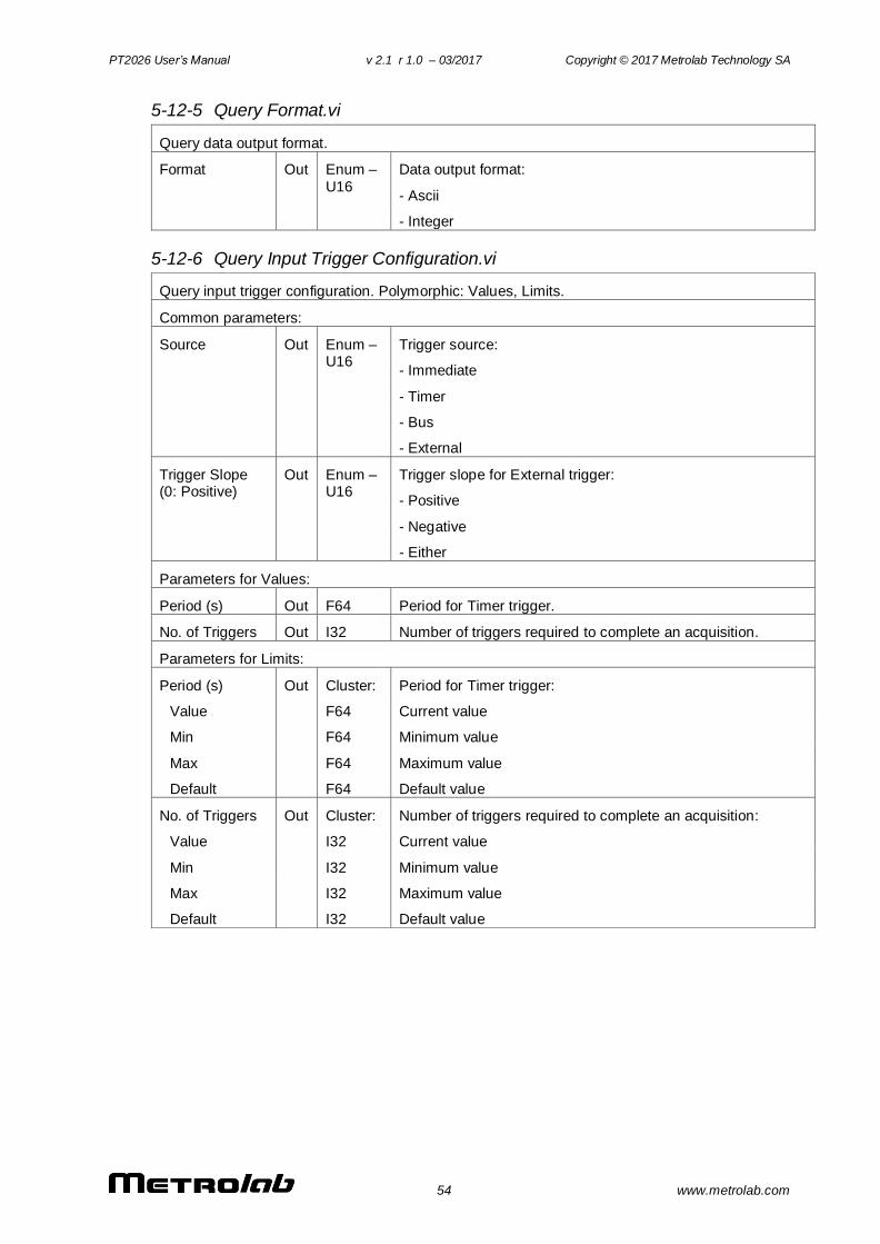
PT2026 User’s Manual v 2.1 r 1.0 – 03/2017 Copyright © 2017 Metrolab Technology SA
54 www.metrolab.com
5-12-5 Query Format.vi
Query data output format.
Format Out Enum –
U16
Data output format:
- Ascii
- Integer
5-12-6 Query Input Trigger Configuration.vi
Query input trigger configuration. Polymorphic: Values, Limits.
Common parameters:
Source Out Enum – U16
Trigger source:
- Immediate
- Timer
- Bus
- External
Trigger Slope (0: Positive)
Out Enum – U16
Trigger slope for External trigger:
- Positive
- Negative
- Either
Parameters for Values:
Period (s) Out F64 Period for Timer trigger.
No. of Triggers Out I32 Number of triggers required to complete an acquisition.
Parameters for Limits:
Period (s) Out Cluster: Period for Timer trigger:
Value F64 Current value
Min F64 Minimum value
Max F64 Maximum value
Default F64 Default value
No. of Triggers Out Cluster: Number of triggers required to complete an acquisition:
Value I32 Current value
Min I32 Minimum value
Max I32 Maximum value
Default I32 Default value
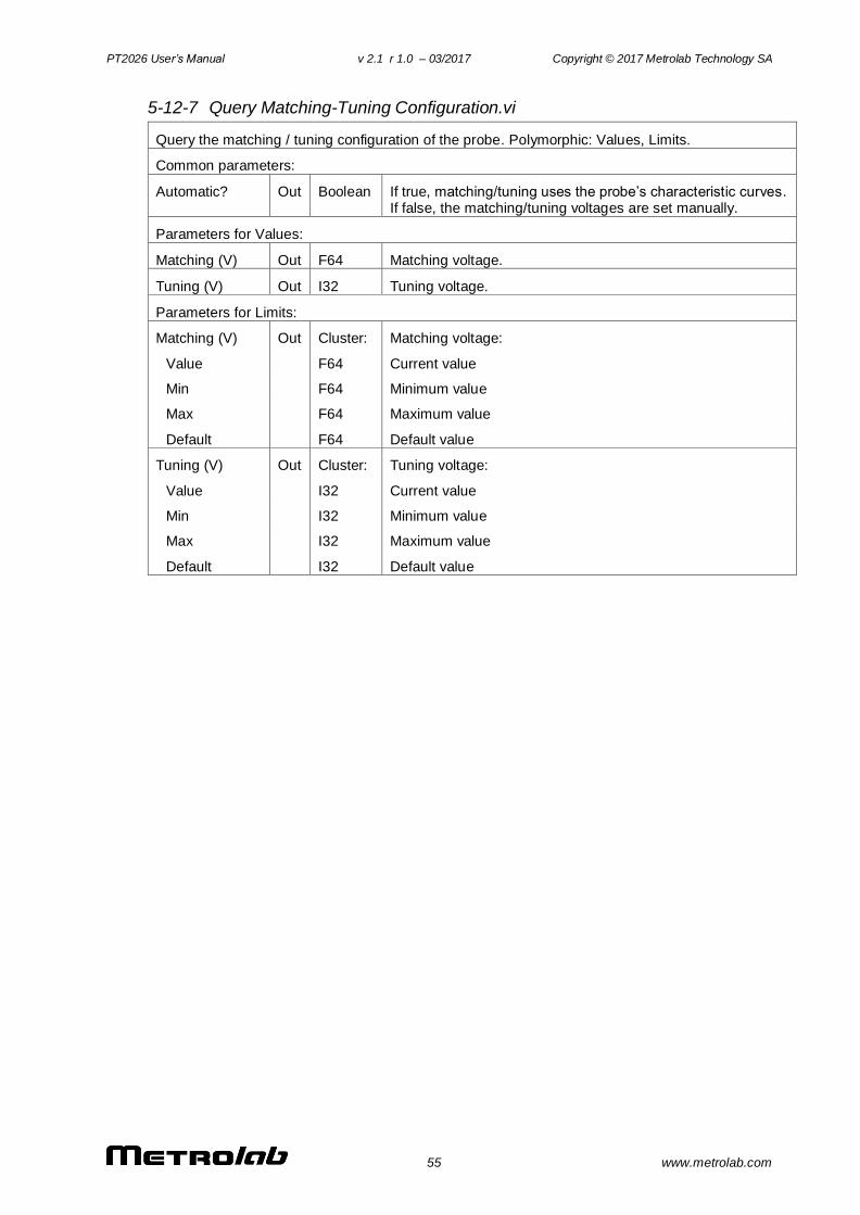
PT2026 User’s Manual v 2.1 r 1.0 – 03/2017 Copyright © 2017 Metrolab Technology SA
55 www.metrolab.com
5-12-7 Query Matching-Tuning Configuration.vi
Query the matching / tuning configuration of the probe. Polymorphic: Values, Limits.
Common parameters:
Automatic? Out Boolean If true, matching/tuning uses the probe’s characteristic curves. If false, the matching/tuning voltages are set manually.
Parameters for Values:
Matching (V) Out F64 Matching voltage.
Tuning (V) Out I32 Tuning voltage.
Parameters for Limits:
Matching (V) Out Cluster: Matching voltage:
Value F64 Current value
Min F64 Minimum value
Max F64 Maximum value
Default F64 Default value
Tuning (V) Out Cluster: Tuning voltage:
Value I32 Current value
Min I32 Minimum value
Max I32 Maximum value
Default I32 Default value
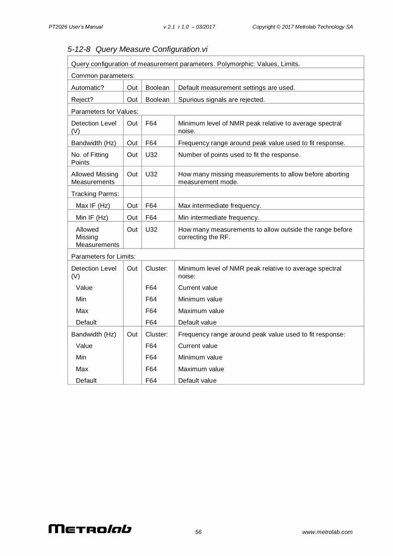
PT2026 User’s Manual v 2.1 r 1.0 – 03/2017 Copyright © 2017 Metrolab Technology SA
56 www.metrolab.com
5-12-8 Query Measure Configuration.vi
Query configuration of measurement parameters. Polymorphic: Values, Limits.
Common parameters:
Automatic? Out Boolean Default measurement settings are used.
Reject? Out Boolean Spurious signals are rejected.
Parameters for Values:
Detection Level
(V)
Out F64 Minimum level of NMR peak relative to average spectral
noise.
Bandwidth (Hz) Out F64 Frequency range around peak value used to fit response.
No. of Fitting
Points
Out U32 Number of points used to fit the response.
Allowed Missing
Measurements
Out U32 How many missing measurements to allow before aborting
measurement mode.
Tracking Parms:
Max IF (Hz) Out F64 Max intermediate frequency.
Min IF (Hz) Out F64 Min intermediate frequency.
Allowed Missing
Measurements
Out U32 How many measurements to allow outside the range before correcting the RF.
Parameters for Limits:
Detection Level
(V)
Out Cluster: Minimum level of NMR peak relative to average spectral
noise:
Value F64 Current value
Min F64 Minimum value
Max F64 Maximum value
Default F64 Default value
Bandwidth (Hz) Out Cluster: Frequency range around peak value used to fit response:
Value F64 Current value
Min F64 Minimum value
Max F64 Maximum value
Default F64 Default value
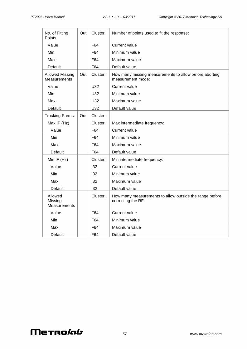
PT2026 User’s Manual v 2.1 r 1.0 – 03/2017 Copyright © 2017 Metrolab Technology SA
57 www.metrolab.com
No. of Fitting
Points
Out Cluster: Number of points used to fit the response:
Value F64 Current value
Min F64 Minimum value
Max F64 Maximum value
Default F64 Default value
Allowed Missing Measurements
Out Cluster: How many missing measurements to allow before aborting measurement mode:
Value U32 Current value
Min U32 Minimum value
Max U32 Maximum value
Default U32 Default value
Tracking Parms: Out Cluster:
Max IF (Hz) Cluster: Max intermediate frequency:
Value F64 Current value
Min F64 Minimum value
Max F64 Maximum value
Default F64 Default value
Min IF (Hz) Cluster: Min intermediate frequency:
Value I32 Current value
Min I32 Minimum value
Max I32 Maximum value
Default I32 Default value
Allowed Missing
Measurements
Cluster: How many measurements to allow outside the range before correcting the RF:
Value F64 Current value
Min F64 Minimum value
Max F64 Maximum value
Default F64 Default value
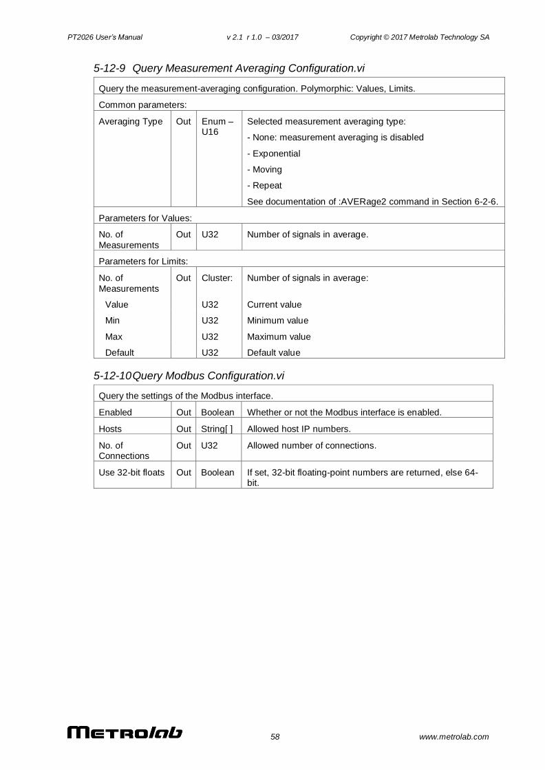
PT2026 User’s Manual v 2.1 r 1.0 – 03/2017 Copyright © 2017 Metrolab Technology SA
58 www.metrolab.com
5-12-9 Query Measurement Averaging Configuration.vi
Query the measurement-averaging configuration. Polymorphic: Values, Limits.
Common parameters:
Averaging Type Out Enum – U16
Selected measurement averaging type:
- None: measurement averaging is disabled
- Exponential
- Moving
- Repeat
See documentation of :AVERage2 command in Section 6-2-6.
Parameters for Values:
No. of
Measurements
Out U32 Number of signals in average.
Parameters for Limits:
No. of
Measurements
Out Cluster: Number of signals in average:
Value U32 Current value
Min U32 Minimum value
Max U32 Maximum value
Default U32 Default value
5-12-10 Query Modbus Configuration.vi
Query the settings of the Modbus interface.
Enabled Out Boolean Whether or not the Modbus interface is enabled.
Hosts Out String[ ] Allowed host IP numbers.
No. of Connections
Out U32 Allowed number of connections.
Use 32-bit floats Out Boolean If set, 32-bit floating-point numbers are returned, else 64-bit.
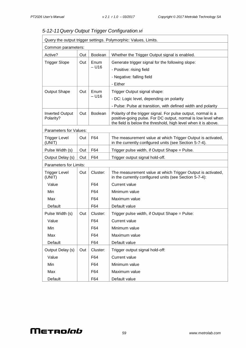
PT2026 User’s Manual v 2.1 r 1.0 – 03/2017 Copyright © 2017 Metrolab Technology SA
59 www.metrolab.com
5-12-11 Query Output Trigger Configuration.vi
Query the output trigger settings. Polymorphic: Values, Limits.
Common parameters:
Active? Out Boolean Whether the Trigger Output signal is enabled.
Trigger Slope Out Enum – U16
Generate trigger signal for the following slope:
- Positive: rising field
- Negative: falling field
- Either
Output Shape Out Enum – U16
Trigger Output signal shape:
- DC: Logic level, depending on polarity
- Pulse: Pulse at transition, with defined width and polarity
Inverted Output Polarity?
Out Boolean Polarity of the trigger signal. For pulse output, normal is a positive-going pulse. For DC output, normal is low level when
the field is below the threshold, high level when it is above.
Parameters for Values:
Trigger Level
(UNIT)
Out F64 The measurement value at which Trigger Output is activated,
in the currently configured units (see Section 5-7-4).
Pulse Width (s) Out F64 Trigger pulse width, if Output Shape = Pulse.
Output Delay (s) Out F64 Trigger output signal hold-off.
Parameters for Limits:
Trigger Level (UNIT)
Out Cluster: The measurement value at which Trigger Output is activated, in the currently configured units (see Section 5-7-4):
Value F64 Current value
Min F64 Minimum value
Max F64 Maximum value
Default F64 Default value
Pulse Width (s) Out Cluster: Trigger pulse width, if Output Shape = Pulse:
Value F64 Current value
Min F64 Minimum value
Max F64 Maximum value
Default F64 Default value
Output Delay (s) Out Cluster: Trigger output signal hold-off:
Value F64 Current value
Min F64 Minimum value
Max F64 Maximum value
Default F64 Default value
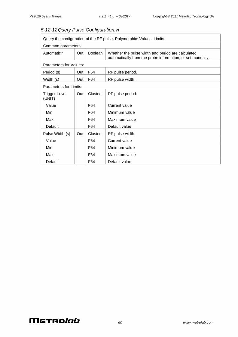
PT2026 User’s Manual v 2.1 r 1.0 – 03/2017 Copyright © 2017 Metrolab Technology SA
60 www.metrolab.com
5-12-12 Query Pulse Configuration.vi
Query the configuration of the RF pulse. Polymorphic: Values, Limits.
Common parameters:
Automatic? Out Boolean Whether the pulse width and period are calculated automatically from the probe information, or set manually.
Parameters for Values:
Period (s) Out F64 RF pulse period.
Width (s) Out F64 RF pulse width.
Parameters for Limits:
Trigger Level
(UNIT)
Out Cluster: RF pulse period:
Value F64 Current value
Min F64 Minimum value
Max F64 Maximum value
Default F64 Default value
Pulse Width (s) Out Cluster: RF pulse width:
Value F64 Current value
Min F64 Minimum value
Max F64 Maximum value
Default F64 Default value
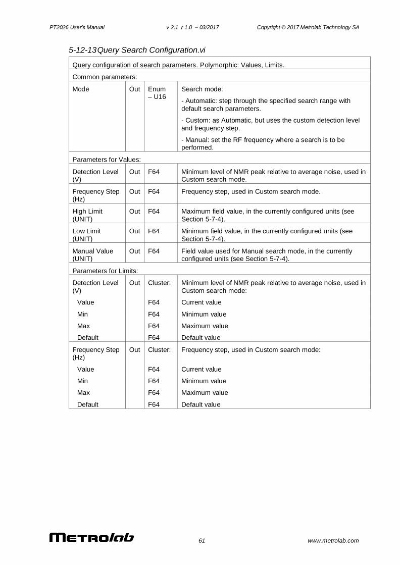
PT2026 User’s Manual v 2.1 r 1.0 – 03/2017 Copyright © 2017 Metrolab Technology SA
61 www.metrolab.com
5-12-13 Query Search Configuration.vi
Query configuration of search parameters. Polymorphic: Values, Limits.
Common parameters:
Mode Out Enum – U16
Search mode:
- Automatic: step through the specified search range with
default search parameters.
- Custom: as Automatic, but uses the custom detection level
and frequency step.
- Manual: set the RF frequency where a search is to be performed.
Parameters for Values:
Detection Level (V)
Out F64 Minimum level of NMR peak relative to average noise, used in Custom search mode.
Frequency Step (Hz)
Out F64 Frequency step, used in Custom search mode.
High Limit
(UNIT)
Out F64 Maximum field value, in the currently configured units (see
Section 5-7-4).
Low Limit
(UNIT)
Out F64 Minimum field value, in the currently configured units (see
Section 5-7-4).
Manual Value (UNIT)
Out F64 Field value used for Manual search mode, in the currently configured units (see Section 5-7-4).
Parameters for Limits:
Detection Level
(V)
Out Cluster: Minimum level of NMR peak relative to average noise, used in
Custom search mode:
Value F64 Current value
Min F64 Minimum value
Max F64 Maximum value
Default F64 Default value
Frequency Step (Hz)
Out Cluster: Frequency step, used in Custom search mode:
Value F64 Current value
Min F64 Minimum value
Max F64 Maximum value
Default F64 Default value
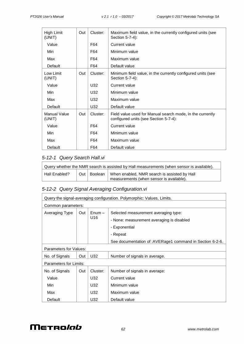
PT2026 User’s Manual v 2.1 r 1.0 – 03/2017 Copyright © 2017 Metrolab Technology SA
62 www.metrolab.com
High Limit
(UNIT)
Out Cluster: Maximum field value, in the currently configured units (see
Section 5-7-4):
Value F64 Current value
Min F64 Minimum value
Max F64 Maximum value
Default F64 Default value
Low Limit (UNIT)
Out Cluster: Minimum field value, in the currently configured units (see Section 5-7-4):
Value U32 Current value
Min U32 Minimum value
Max U32 Maximum value
Default U32 Default value
Manual Value
(UNIT)
Out Cluster: Field value used for Manual search mode, in the currently
configured units (see Section 5-7-4):
Value F64 Current value
Min F64 Minimum value
Max F64 Maximum value
Default F64 Default value
5-12-1 Query Search Hall.vi
Query whether the NMR search is assisted by Hall measurements (when sensor is available).
Hall Enabled? Out Boolean When enabled, NMR search is assisted by Hall
measurements (when sensor is available).
5-12-2 Query Signal Averaging Configuration.vi
Query the signal-averaging configuration. Polymorphic: Values, Limits.
Common parameters:
Averaging Type Out Enum –
U16
Selected measurement averaging type:
- None: measurement averaging is disabled
- Exponential
- Repeat
See documentation of :AVERage1 command in Section 6-2-6.
Parameters for Values:
No. of Signals Out U32 Number of signals in average.
Parameters for Limits:
No. of Signals Out Cluster: Number of signals in average:
Value U32 Current value
Min U32 Minimum value
Max U32 Maximum value
Default U32 Default value
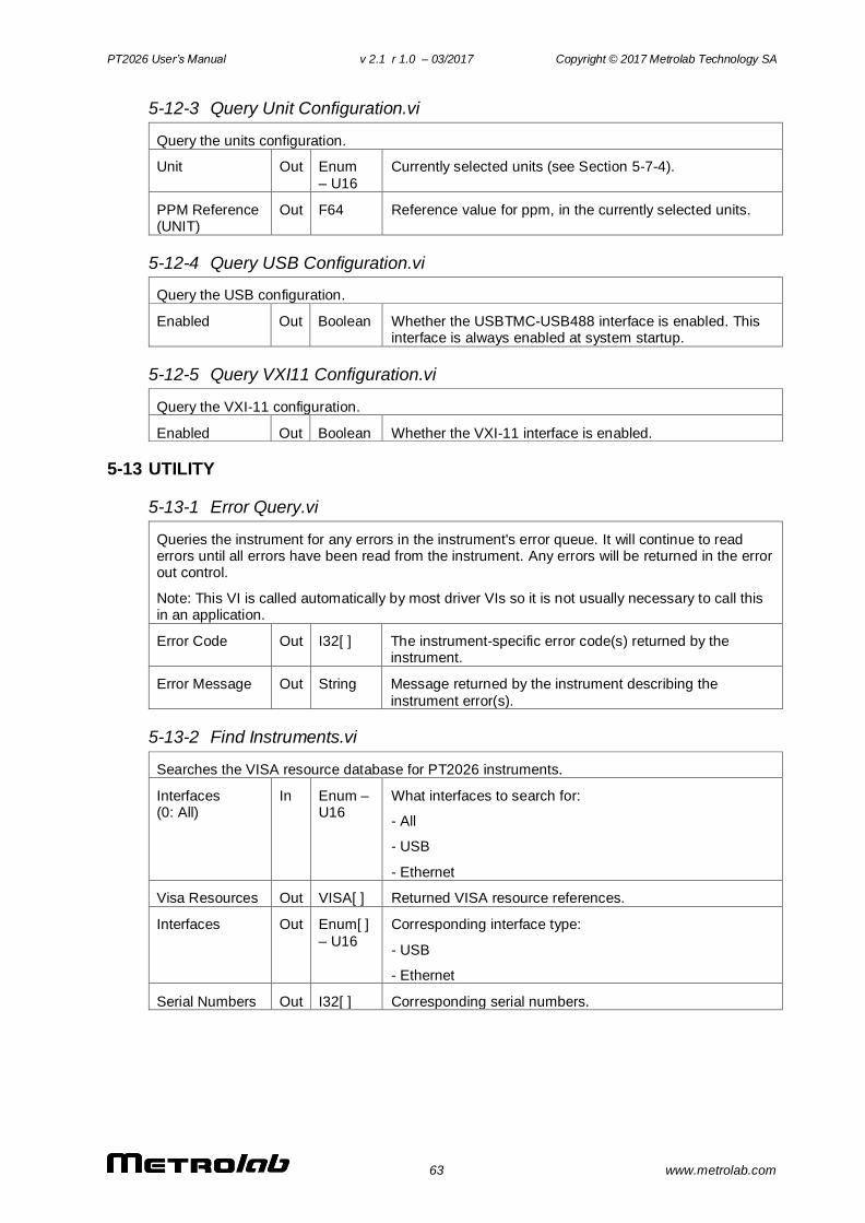
PT2026 User’s Manual v 2.1 r 1.0 – 03/2017 Copyright © 2017 Metrolab Technology SA
63 www.metrolab.com
5-12-3 Query Unit Configuration.vi
Query the units configuration.
Unit Out Enum
– U16
Currently selected units (see Section 5-7-4).
PPM Reference (UNIT)
Out F64 Reference value for ppm, in the currently selected units.
5-12-4 Query USB Configuration.vi
Query the USB configuration.
Enabled Out Boolean Whether the USBTMC-USB488 interface is enabled. This interface is always enabled at system startup.
5-12-5 Query VXI11 Configuration.vi
Query the VXI-11 configuration.
Enabled Out Boolean Whether the VXI-11 interface is enabled.
5-13 UTILITY
5-13-1 Error Query.vi
Queries the instrument for any errors in the instrument's error queue. It will continue to read errors until all errors have been read from the instrument. Any errors will be returned in the error out control.
Note: This VI is called automatically by most driver VIs so it is not usually necessary to call this in an application.
Error Code Out I32[ ] The instrument-specific error code(s) returned by the instrument.
Error Message Out String Message returned by the instrument describing the
instrument error(s).
5-13-2 Find Instruments.vi
Searches the VISA resource database for PT2026 instruments.
Interfaces (0: All)
In Enum – U16
What interfaces to search for:
- All
- USB
- Ethernet
Visa Resources Out VISA[ ] Returned VISA resource references.
Interfaces Out Enum[ ]
– U16
Corresponding interface type:
- USB
- Ethernet
Serial Numbers Out I32[ ] Corresponding serial numbers.
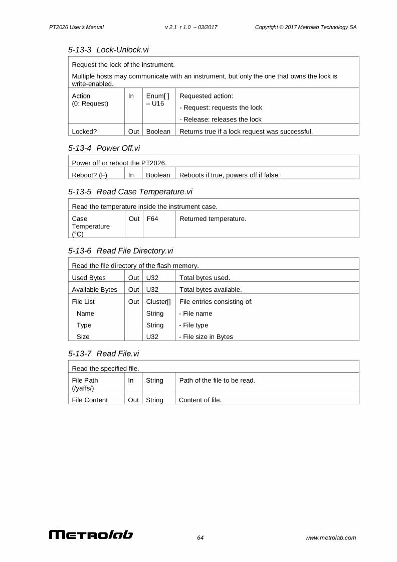
PT2026 User’s Manual v 2.1 r 1.0 – 03/2017 Copyright © 2017 Metrolab Technology SA
64 www.metrolab.com
5-13-3 Lock-Unlock.vi
Request the lock of the instrument.
Multiple hosts may communicate with an instrument, but only the one that owns the lock is write-enabled.
Action (0: Request)
In Enum[ ] – U16
Requested action:
- Request: requests the lock
- Release: releases the lock
Locked? Out Boolean Returns true if a lock request was successful.
5-13-4 Power Off.vi
Power off or reboot the PT2026.
Reboot? (F) In Boolean Reboots if true, powers off if false.
5-13-5 Read Case Temperature.vi
Read the temperature inside the instrument case.
Case Temperature
(°C)
Out F64
Returned temperature.
5-13-6 Read File Directory.vi
Read the file directory of the flash memory.
Used Bytes Out U32 Total bytes used.
Available Bytes Out U32 Total bytes available.
File List Out Cluster[] File entries consisting of:
Name String - File name
Type String - File type
Size U32 - File size in Bytes
5-13-7 Read File.vi
Read the specified file.
File Path
(/yaffs/)
In String Path of the file to be read.
File Content Out String Content of file.
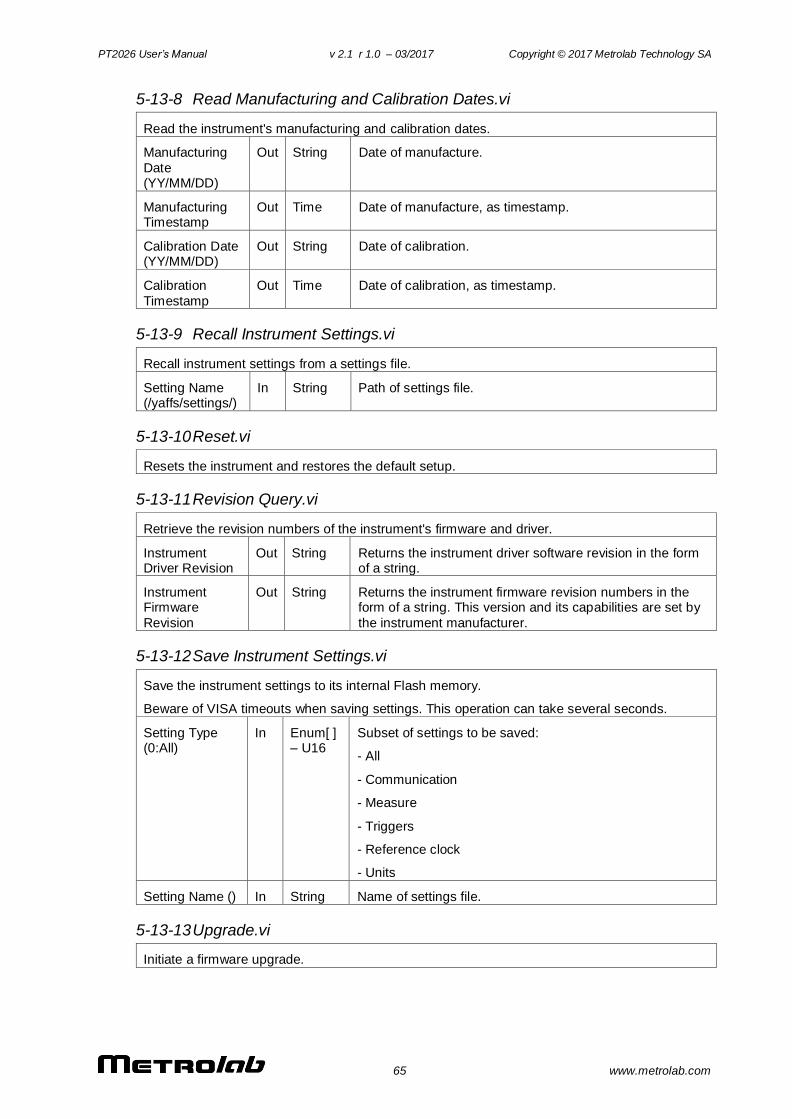
PT2026 User’s Manual v 2.1 r 1.0 – 03/2017 Copyright © 2017 Metrolab Technology SA
65 www.metrolab.com
5-13-8 Read Manufacturing and Calibration Dates.vi
Read the instrument's manufacturing and calibration dates.
Manufacturing
Date (YY/MM/DD)
Out String Date of manufacture.
Manufacturing Timestamp
Out Time Date of manufacture, as timestamp.
Calibration Date (YY/MM/DD)
Out String Date of calibration.
Calibration
Timestamp
Out Time Date of calibration, as timestamp.
5-13-9 Recall Instrument Settings.vi
Recall instrument settings from a settings file.
Setting Name (/yaffs/settings/)
In String Path of settings file.
5-13-10 Reset.vi
Resets the instrument and restores the default setup.
5-13-11 Revision Query.vi
Retrieve the revision numbers of the instrument's firmware and driver.
Instrument Driver Revision
Out String Returns the instrument driver software revision in the form of a string.
Instrument Firmware
Revision
Out String Returns the instrument firmware revision numbers in the form of a string. This version and its capabilities are set by
the instrument manufacturer.
5-13-12 Save Instrument Settings.vi
Save the instrument settings to its internal Flash memory.
Beware of VISA timeouts when saving settings. This operation can take several seconds.
Setting Type (0:All)
In Enum[ ] – U16
Subset of settings to be saved:
- All
- Communication
- Measure
- Triggers
- Reference clock
- Units
Setting Name () In String Name of settings file.
5-13-13 Upgrade.vi
Initiate a firmware upgrade.
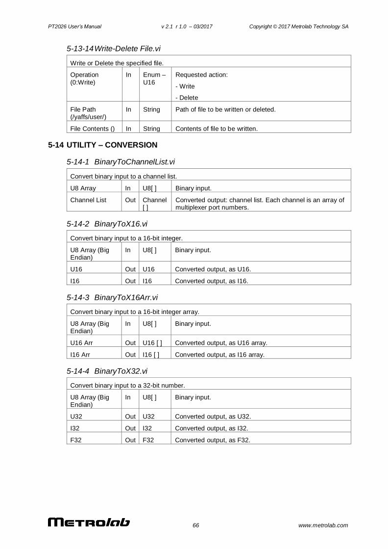
PT2026 User’s Manual v 2.1 r 1.0 – 03/2017 Copyright © 2017 Metrolab Technology SA
66 www.metrolab.com
5-13-14 Write-Delete File.vi
Write or Delete the specified file.
Operation
(0:Write)
In Enum –
U16
Requested action:
- Write
- Delete
File Path (/yaffs/user/)
In String Path of file to be written or deleted.
File Contents () In String Contents of file to be written.
5-14 UTILITY – CONVERSION
5-14-1 BinaryToChannelList.vi
Convert binary input to a channel list.
U8 Array In U8[ ] Binary input.
Channel List Out Channel [ ]
Converted output: channel list. Each channel is an array of multiplexer port numbers.
5-14-2 BinaryToX16.vi
Convert binary input to a 16-bit integer.
U8 Array (Big Endian)
In U8[ ] Binary input.
U16 Out U16 Converted output, as U16.
I16 Out I16 Converted output, as I16.
5-14-3 BinaryToX16Arr.vi
Convert binary input to a 16-bit integer array.
U8 Array (Big Endian)
In U8[ ] Binary input.
U16 Arr Out U16 [ ] Converted output, as U16 array.
I16 Arr Out I16 [ ] Converted output, as I16 array.
5-14-4 BinaryToX32.vi
Convert binary input to a 32-bit number.
U8 Array (Big Endian)
In U8[ ] Binary input.
U32 Out U32 Converted output, as U32.
I32 Out I32 Converted output, as I32.
F32 Out F32 Converted output, as F32.
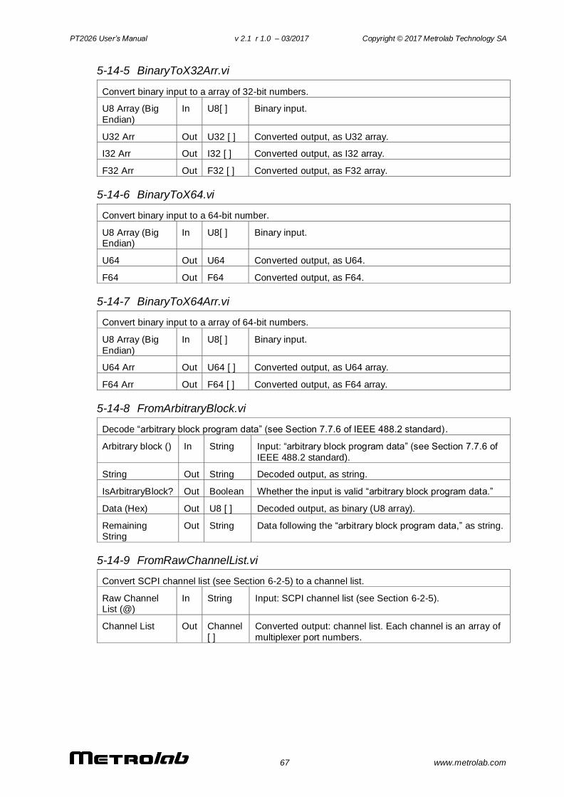
PT2026 User’s Manual v 2.1 r 1.0 – 03/2017 Copyright © 2017 Metrolab Technology SA
67 www.metrolab.com
5-14-5 BinaryToX32Arr.vi
Convert binary input to a array of 32-bit numbers.
U8 Array (Big
Endian)
In U8[ ] Binary input.
U32 Arr Out U32 [ ] Converted output, as U32 array.
I32 Arr Out I32 [ ] Converted output, as I32 array.
F32 Arr Out F32 [ ] Converted output, as F32 array.
5-14-6 BinaryToX64.vi
Convert binary input to a 64-bit number.
U8 Array (Big Endian)
In U8[ ] Binary input.
U64 Out U64 Converted output, as U64.
F64 Out F64 Converted output, as F64.
5-14-7 BinaryToX64Arr.vi
Convert binary input to a array of 64-bit numbers.
U8 Array (Big
Endian)
In U8[ ] Binary input.
U64 Arr Out U64 [ ] Converted output, as U64 array.
F64 Arr Out F64 [ ] Converted output, as F64 array.
5-14-8 FromArbitraryBlock.vi
Decode “arbitrary block program data” (see Section 7.7.6 of IEEE 488.2 standard) .
Arbitrary block () In String Input: “arbitrary block program data” (see Section 7.7.6 of
IEEE 488.2 standard).
String Out String Decoded output, as string.
IsArbitraryBlock? Out Boolean Whether the input is valid “arbitrary block program data.”
Data (Hex) Out U8 [ ] Decoded output, as binary (U8 array).
Remaining String
Out String Data following the “arbitrary block program data,” as string.
5-14-9 FromRawChannelList.vi
Convert SCPI channel list (see Section 6-2-5) to a channel list.
Raw Channel List (@)
In String Input: SCPI channel list (see Section 6-2-5).
Channel List Out Channel
[ ]
Converted output: channel list. Each channel is an array of
multiplexer port numbers.
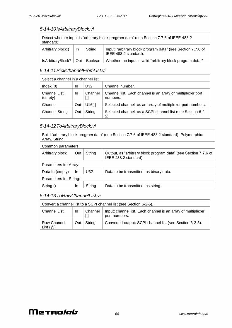
PT2026 User’s Manual v 2.1 r 1.0 – 03/2017 Copyright © 2017 Metrolab Technology SA
68 www.metrolab.com
5-14-10 IsArbitraryBlock.vi
Detect whether input is “arbitrary block program data” (see Section 7.7.6 of IEEE 488.2 standard).
Arbitrary block () In String Input: “arbitrary block program data” (see Section 7.7.6 of IEEE 488.2 standard).
IsArbitraryBlock? Out Boolean Whether the input is valid “arbitrary block program data.”
5-14-11 PickChannelFromList.vi
Select a channel in a channel list.
Index (0) In U32 Channel number.
Channel List (empty)
In Channel [ ]
Channel list. Each channel is an array of multiplexer port numbers.
Channel Out U16[ ] Selected channel, as an array of multiplexer port numbers.
Channel String Out String Selected channel, as a SCPI channel list (see Section 6-2-5).
5-14-12 ToArbitraryBlock.vi
Build “arbitrary block program data” (see Section 7.7.6 of IEEE 488.2 standard). Polymorphic: Array, String.
Common parameters:
Arbitrary block Out String Output, as “arbitrary block program data” (see Section 7.7.6 of
IEEE 488.2 standard).
Parameters for Array:
Data In (empty) In U32 Data to be transmitted, as binary data.
Parameters for String:
String () In String Data to be transmitted, as string.
5-14-13 ToRawChannelList.vi
Convert a channel list to a SCPI channel list (see Section 6-2-5).
Channel List In Channel [ ]
Input: channel list. Each channel is an array of multiplexer port numbers.
Raw Channel List (@)
Out String Converted output: SCPI channel list (see Section 6-2-5).
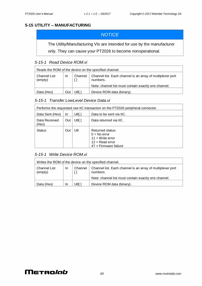
PT2026 User’s Manual v 2.1 r 1.0 – 03/2017 Copyright © 2017 Metrolab Technology SA
69 www.metrolab.com
5-15 UTILITY – MANUFACTURING
NOTICE
The Utility/Manufacturing VIs are intended for use by the manufacturer
only. They can cause your PT2026 to become nonoperational.
5-15-1 Read Device ROM.vi
Reads the ROM of the device on the specified channel.
Channel List (empty)
In Channel [ ]
Channel list. Each channel is an array of multiplexer port numbers.
Note: channel list must contain exactly one channel.
Data (Hex) Out U8[ ] Device ROM data (binary).
5-15-1 Transfer LowLevel Device Data.vi
Performs the requested raw IIC transaction on the PT2026 peripheral connector.
Data Sent (Hex) In U8[ ] Data to be sent via IIC.
Data Received
(Hex)
Out U8[ ] Data returned via IIC.
Status Out U8 Returned status: 0 = No error 11 = Write error
12 = Read error 47 = Firmware failure
5-15-1 Write Device ROM.vi
Writes the ROM of the device on the specified channel.
Channel List
(empty)
In Channel
[ ]
Channel list. Each channel is an array of multiplexer port
numbers.
Note: channel list must contain exactly one channel.
Data (Hex) In U8[ ] Device ROM data (binary).
PT2026 User’s Manual v 2.1 r 1.0 – 03/2017 Copyright © 2017 Metrolab Technology SA
70 www.metrolab.com
PROGRAMMING THE PT2026
6- Host Interfaces
6-1 GENERAL
The PT2026 supports two physical host interfaces, USB 2.0 and Ethernet, and
two host interface protocols: “native” and “MODBUS.” The native protocol is
based on the following standards, very widespread in the instrumentation industry:
- IEEE 488.2: device control,
- VXI-11: Ethernet device control,
- USBTMC-USB488: USB device control, and
- SCPI: command structure.
The native commands provide access to all the features of the PT2026. The same
command set is supported on the USB and Ethernet interfaces.
The MODBUS protocol is commonly used in industrial automation applications.
The PT2026 supports the MODBUS protocol only on the Ethernet interface, and it
only provides access to a subset of the instrument’s functionality.
NOTICE
The MODBUS interface protocol is not yet implemented.
If you use the turnkey software or the LabVIEW instrument driver, it is generally
not necessary to refer to the information in this chapter. You may, however, want
to write a program optimized for your application, without using the LabVIEW
instrument driver provided by Metrolab. This chapter will provide you with the
information necessary to do so.
The PT2026 was designed to plug-and-play with a Virtual Instrument Software
Architecture (VISA) compliant software library – in particular, the NI-VISA library
from National Instruments (see www.ni.com). If you are not using NI-VISA, you
will probably need information that is not provided in this chapter:
USB 2.0
See “Universal Serial Bus Specification, Revision 2.0, April 27, 2000,”
available from www.usb.org/developers/docs/usb20_docs.
PT2026 User’s Manual v 2.1 r 1.0 – 03/2017 Copyright © 2017 Metrolab Technology SA
71 www.metrolab.com
USBTMC and USBTMC-USB488
See “Universal Serial Bus Test and Measurement Class Specification
(USBTMC), Revision 1.0, April 14, 2003” and “Universal Serial Bus Test
and Measurement Class, Subclass USB488 Specification (USBTMC-
USB488), Revision 1.0, April 14, 2003,” available from
www.usb.org/developers/docs/devclass_docs.
SCPI
See “Standard Commands for Programmable Instruments (SCPI),
VERSION 1999.0, May, 1999,” available from
www.ivifoundation.org/specifications/default.aspx.
IEEE 488.2
See “IEEE Standard Codes, Formats, Protocols, and Common Commands
for Use With IEEE Std 488.1-1987, IEEE Standard Digital Interface for
Programmable Instrumentation, IEEE Std 488.2-1992,” available from
standards.ieee.org/reading/ieee/std_public/description/im/488.2-
1992_desc.html.
VISA
See “VPP-4.3: The VISA Library,” “VPP-4.3.2: VISA Implementation
Specification for Textual Languages,” “VPP-4.3.3: VISA Implementation
Specification for the G Language,” VPP-4.3.4: VISA Implementation
Specification for COM,” all Revision 2.2 (March 17, 2000) by the VXI plug &
play Systems Alliance, available from
www.ivifoundation.org/specifications/default.aspx.
6-2 NATIVE INTERFACES
6-2-1 SCPI instrument model
The PT2026 complies with the Standard Commands for Programmable
instruments (SCPI) standard. SCPI uses a standard instrument model to organize
the command structure. The diagram below shows the subsystems concerning
the signal flow.
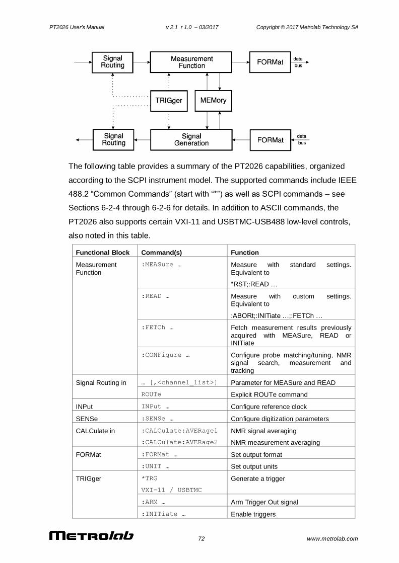
PT2026 User’s Manual v 2.1 r 1.0 – 03/2017 Copyright © 2017 Metrolab Technology SA
72 www.metrolab.com
The following table provides a summary of the PT2026 capabilities, organized
according to the SCPI instrument model. The supported commands include IEEE
488.2 “Common Commands” (start with “*”) as well as SCPI commands – see
Sections 6-2-4 through 6-2-6 for details. In addition to ASCII commands, the
PT2026 also supports certain VXI-11 and USBTMC-USB488 low-level controls,
also noted in this table.
Functional Block Command(s) Function
Measurement
Function
:MEASure … Measure with standard settings.
Equivalent to
*RST;:READ …
:READ … Measure with custom settings. Equivalent to
:ABORt;:INITiate …;:FETCh …
:FETCh … Fetch measurement results previously
acquired with MEASure, READ or INITiate
:CONFigure … Configure probe matching/tuning, NMR signal search, measurement and
tracking
Signal Routing in … [,<channel_list>] Parameter for MEASure and READ
ROUTe Explicit ROUTe command
INPut INPut … Configure reference clock
SENSe :SENSe … Configure digitization parameters
CALCulate in :CALCulate:AVERage1
:CALCulate:AVERage2
NMR signal averaging
NMR measurement averaging
FORMat :FORMat … Set output format
:UNIT … Set output units
TRIGger *TRG
VXI-11 / USBTMC
Generate a trigger
:ARM … Arm Trigger Out signal
:INITiate … Enable triggers
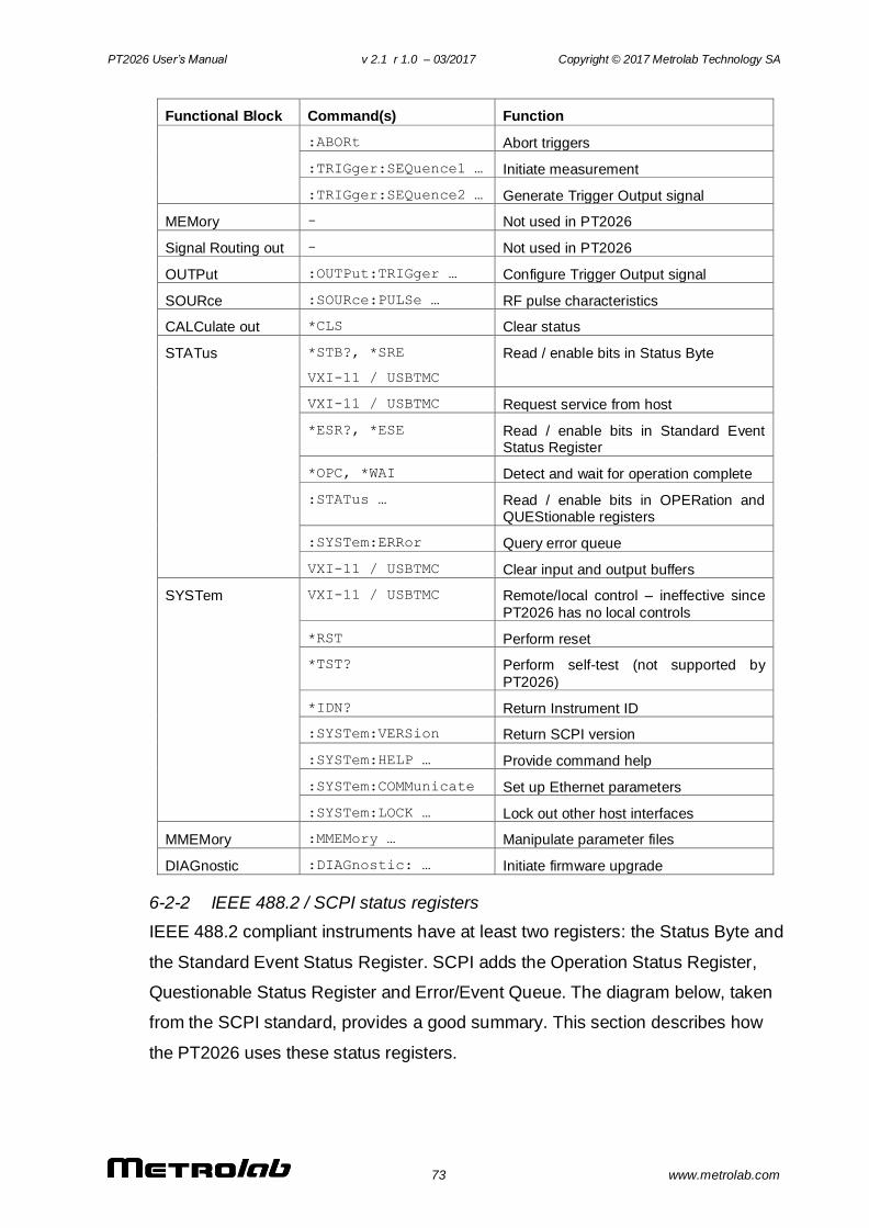
PT2026 User’s Manual v 2.1 r 1.0 – 03/2017 Copyright © 2017 Metrolab Technology SA
73 www.metrolab.com
Functional Block Command(s) Function
:ABORt Abort triggers
:TRIGger:SEQuence1 … Initiate measurement
:TRIGger:SEQuence2 … Generate Trigger Output signal
MEMory - Not used in PT2026
Signal Routing out - Not used in PT2026
OUTPut :OUTPut:TRIGger … Configure Trigger Output signal
SOURce :SOURce:PULSe … RF pulse characteristics
CALCulate out *CLS Clear status
STATus *STB?, *SRE
VXI-11 / USBTMC
Read / enable bits in Status Byte
VXI-11 / USBTMC Request service from host
*ESR?, *ESE Read / enable bits in Standard Event Status Register
*OPC, *WAI Detect and wait for operation complete
:STATus … Read / enable bits in OPERation and QUEStionable registers
:SYSTem:ERRor Query error queue
VXI-11 / USBTMC Clear input and output buffers
SYSTem VXI-11 / USBTMC Remote/local control – ineffective since
PT2026 has no local controls
*RST Perform reset
*TST? Perform self-test (not supported by
PT2026)
*IDN? Return Instrument ID
:SYSTem:VERSion Return SCPI version
:SYSTem:HELP … Provide command help
:SYSTem:COMMunicate Set up Ethernet parameters
:SYSTem:LOCK … Lock out other host interfaces
MMEMory :MMEMory … Manipulate parameter files
DIAGnostic :DIAGnostic: … Initiate firmware upgrade
6-2-2 IEEE 488.2 / SCPI status registers
IEEE 488.2 compliant instruments have at least two registers: the Status Byte and
the Standard Event Status Register. SCPI adds the Operation Status Register,
Questionable Status Register and Error/Event Queue. The diagram below, taken
from the SCPI standard, provides a good summary. This section describes how
the PT2026 uses these status registers.
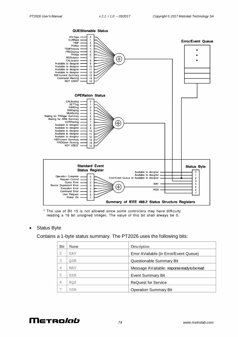
PT2026 User’s Manual v 2.1 r 1.0 – 03/2017 Copyright © 2017 Metrolab Technology SA
74 www.metrolab.com
Status Byte
Contains a 1-byte status summary. The PT2026 uses the following bits:
Bit Name Description
2 EAV Error AVailable (in Error/Event Queue)
3 QSB Questionable Summary Bit
4 MAV Message AVailable: response ready to be read
5 ESB Event Summary Bit
6 RQS ReQuest for Service
7 OSB Operation Summary Bit
PT2026 User’s Manual v 2.1 r 1.0 – 03/2017 Copyright © 2017 Metrolab Technology SA
75 www.metrolab.com
Standard Event Status Register
Latches certain standardized events. The PT2026 uses the following bits:
Bit Name Description
0 Operation Complete *OPC has flagged operation complete
2 Query Error Error in preceding query
3 Device Dependent Error Errors specific to the PT2026, including internal errors
4 Execution Error Error detected during command execution
5 Command Error Error in preceding command
6 User Request A parameter has been changed
7 Power On PT2026 has been powered up
QUEStionable Status
Indicates conditions that may reduce the quality of the measurement. The
PT2026 sets the following bits:
Bit Name Description
9 Unable to measure Unable to acquire and measure an NMR signal
10 Ignored setting A setting was set, but is not taken into account because of other settings
11 Measurement The quality of the measurement is questionable (e.g. Due to unknown IF in
manual search mode)
12 BIT12 Summary Bit: DSP Status
QUEStionable:BIT12
This is a fan-out for bit 12 of the QUEStionable register, a device-specific
summary bit.
Bit Name Description
0 External Ref Detected External reference clock is detected
1 External Ref Locked Locked onto external reference clock
2 Beating Detected Measurement was rejected as spurious signal
(cf. :CONFigure:MEASure:REJect command)
PT2026 User’s Manual v 2.1 r 1.0 – 03/2017 Copyright © 2017 Metrolab Technology SA
76 www.metrolab.com
OPERation Status
Captures conditions which are part of the instrument’s normal operation.
The PT2026 uses the following bits:
Bit Name Description
2 RANGing Scanning for available probes
3 SWEeping Searching for NMR signal
4 MEASuring Measuring magnetic field strength
5 Waiting for TRIGger Waiting for trigger
8 New Acq Avail New Acquisition Data is Available
9 New Meas Avail New Measurement Available
11 BIT11 Summary Bit: A parameter has changed
12 BIT12 Summary Bit: Acquisition status
OPERation:BIT11
This is a fan-out for bit 11 of the OPERation register, a device-specific
summary bit. It indicates subsystems whose configuration has changed.
Bit Name Description
0 SYSTem System: system ID, communications, lock
1 STATus Status: enable bits
2 MEMory Memory: parameter file loaded
3 MMEMory Mass memory: parameters saved, created, deleted
4 CONFigure Measurement: matching/tuning, search,
tracking
5 ROUTe Route: channel selection
6 INPut Input: reference clock
7 OUTput Output: trigger output signal
8 SENse Sense: digitization
9 SOURce Source: pulse
10 TRIGger Trigger: measurement trigger, output trigger
11 CALCulate Calculate: signal & measurement averaging
12 FORMat Format: output format
13 UNIT Units: output units
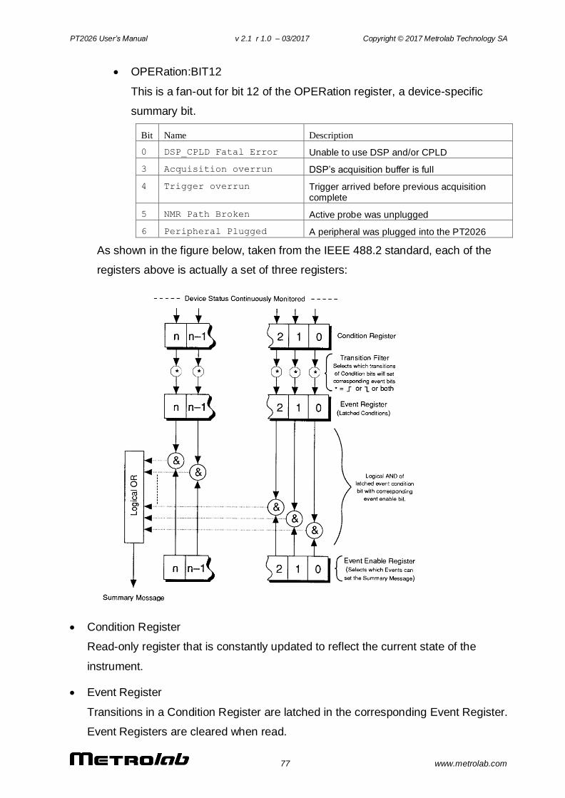
PT2026 User’s Manual v 2.1 r 1.0 – 03/2017 Copyright © 2017 Metrolab Technology SA
77 www.metrolab.com
OPERation:BIT12
This is a fan-out for bit 12 of the OPERation register, a device-specific
summary bit.
Bit Name Description
0 DSP_CPLD Fatal Error Unable to use DSP and/or CPLD
3 Acquisition overrun DSP’s acquisition buffer is full
4 Trigger overrun Trigger arrived before previous acquisition complete
5 NMR Path Broken Active probe was unplugged
6 Peripheral Plugged A peripheral was plugged into the PT2026
As shown in the figure below, taken from the IEEE 488.2 standard, each of the
registers above is actually a set of three registers:
Condition Register
Read-only register that is constantly updated to reflect the current state of the
instrument.
Event Register
Transitions in a Condition Register are latched in the corresponding Event Register.
Event Registers are cleared when read.
PT2026 User’s Manual v 2.1 r 1.0 – 03/2017 Copyright © 2017 Metrolab Technology SA
78 www.metrolab.com
Event Enable Register
A mask indicating what bits in the Event Register are included in the Summary bit.
The enable mask of the Status Byte is called the Status Enable register, and it
determines which bits cause an RQS (ReQuest for Service).
In addition, transition filters are supported for the following register sets:
QUEStionable, QUEStionable:BIT12, OPERation, OPERation:BIT11, and
OPERation:BIT12. Transition filters are used to detect events with positive
transitions (false to true) and/or negative transitions (true to false). By default, only
positive transitions are detected.
Note that some Condition Register bits signal permanent conditions – for example
Power On – and others signal transient events – for example, Command Error.
Reading a Condition Register will provide no indication of transient events; only
the corresponding Event Register will catch such events.
Also note that for efficiency reasons, status register updates are deferred to the
extent possible, and are normally performed only at end of each sequence of
commands separated by semicolons. This also means that a ReQuest for Service
(RQS) is normally generated only at the end of such a sequence. There are
exceptions to this deferral rule, for example if the command sequence includes a
status-query command.
Finally, remark that the PT2026 supports multiple IEEE 488.2 connections, and
that each connection uses its own set of status registers. Thus status bits that
only affect one interface – for example Command Error – are not seen by the
other interfaces. However, status bits that indicate general instrument status – in
particular the QUEStionable and OPERation registers – are propagated to all
interfaces. Using this feature, the OPERation:BIT11 registers can serve to
broadcast parameter changes caused by any one interface.
6-2-3 IEEE 488.2 controls
The following low-level functions are defined by the VXI-11 and USBTMC-
USB488 protocols. Excluded are the functions that are fundamental to the
operation – e.g. in VXI-11: create_link, destroy_link, device_write, device_read,
create_intr_chan, destroy_intr_chan, device_enable_srq, device_intr_srq, and
device_abort.
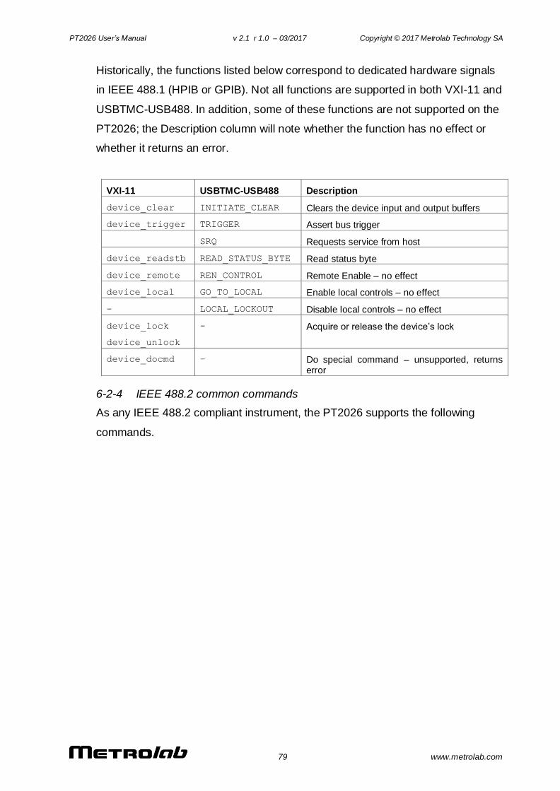
PT2026 User’s Manual v 2.1 r 1.0 – 03/2017 Copyright © 2017 Metrolab Technology SA
79 www.metrolab.com
Historically, the functions listed below correspond to dedicated hardware signals
in IEEE 488.1 (HPIB or GPIB). Not all functions are supported in both VXI-11 and
USBTMC-USB488. In addition, some of these functions are not supported on the
PT2026; the Description column will note whether the function has no effect or
whether it returns an error.
VXI-11 USBTMC-USB488 Description
device_clear INITIATE_CLEAR Clears the device input and output buffers
device_trigger TRIGGER Assert bus trigger
SRQ Requests service from host
device_readstb READ_STATUS_BYTE Read status byte
device_remote REN_CONTROL Remote Enable – no effect
device_local GO_TO_LOCAL Enable local controls – no effect
- LOCAL_LOCKOUT Disable local controls – no effect
device_lock
device_unlock
- Acquire or release the device’s lock
device_docmd – Do special command – unsupported, returns error
6-2-4 IEEE 488.2 common commands
As any IEEE 488.2 compliant instrument, the PT2026 supports the following
commands.
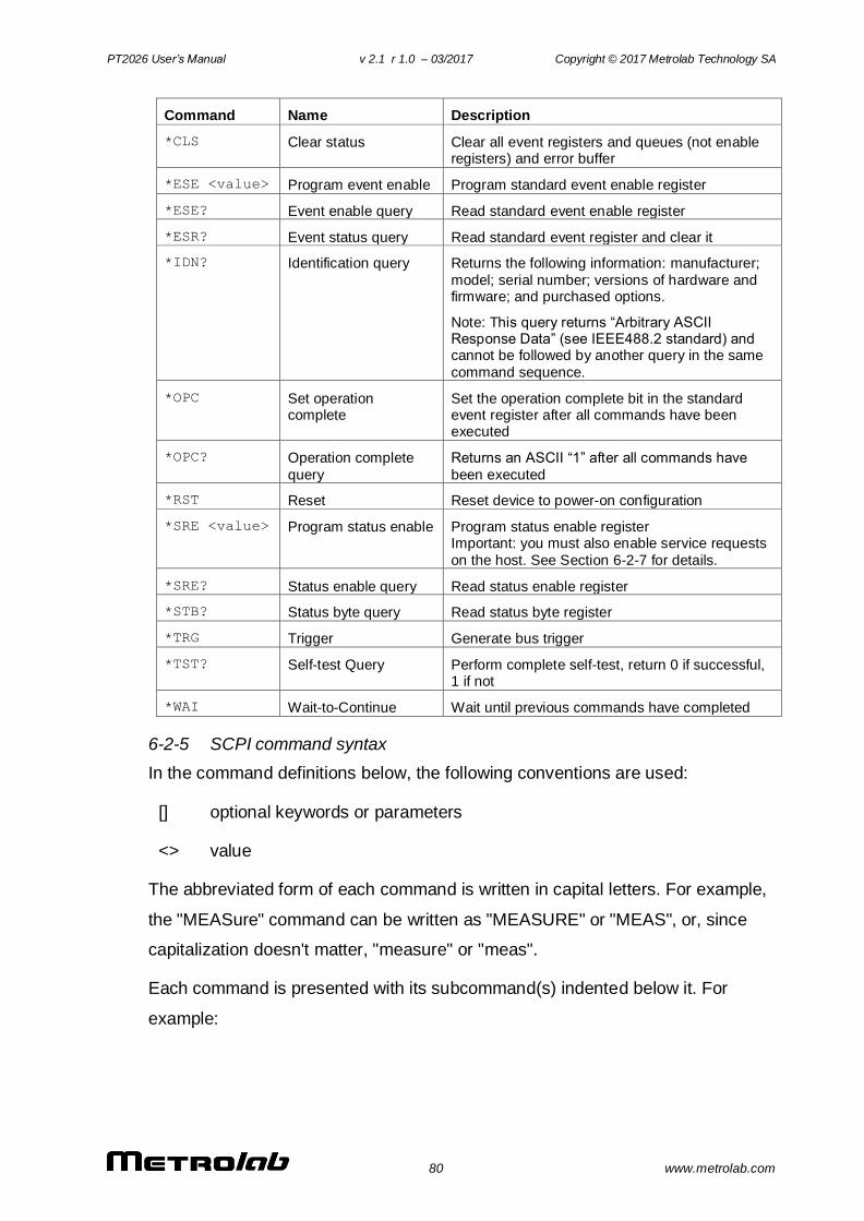
PT2026 User’s Manual v 2.1 r 1.0 – 03/2017 Copyright © 2017 Metrolab Technology SA
80 www.metrolab.com
Command Name Description
*CLS Clear status Clear all event registers and queues (not enable registers) and error buffer
*ESE <value> Program event enable Program standard event enable register
*ESE? Event enable query Read standard event enable register
*ESR? Event status query Read standard event register and clear it
*IDN? Identification query Returns the following information: manufacturer;
model; serial number; versions of hardware and firmware; and purchased options.
Note: This query returns “Arbitrary ASCII Response Data” (see IEEE488.2 standard) and cannot be followed by another query in the same
command sequence.
*OPC Set operation complete
Set the operation complete bit in the standard event register after all commands have been executed
*OPC? Operation complete
query
Returns an ASCII “1” after all commands have
been executed
*RST Reset Reset device to power-on configuration
*SRE <value> Program status enable Program status enable register Important: you must also enable service requests
on the host. See Section 6-2-7 for details.
*SRE? Status enable query Read status enable register
*STB? Status byte query Read status byte register
*TRG Trigger Generate bus trigger
*TST? Self-test Query Perform complete self-test, return 0 if successful, 1 if not
*WAI Wait-to-Continue Wait until previous commands have completed
6-2-5 SCPI command syntax
In the command definitions below, the following conventions are used:
[] optional keywords or parameters
<> value
The abbreviated form of each command is written in capital letters. For example,
the "MEASure" command can be written as "MEASURE" or "MEAS", or, since
capitalization doesn't matter, "measure" or "meas".
Each command is presented with its subcommand(s) indented below it. For
example:
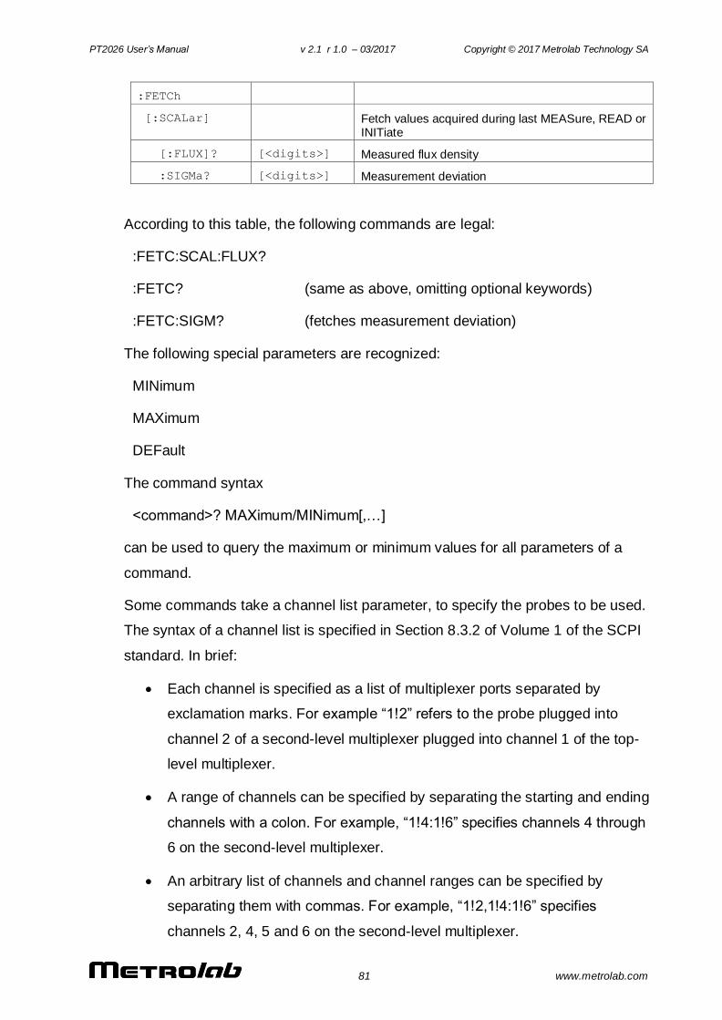
PT2026 User’s Manual v 2.1 r 1.0 – 03/2017 Copyright © 2017 Metrolab Technology SA
81 www.metrolab.com
:FETCh
[:SCALar] Fetch values acquired during last MEASure, READ or INITiate
[:FLUX]? [<digits>] Measured flux density
:SIGMa? [<digits>] Measurement deviation
According to this table, the following commands are legal:
:FETC:SCAL:FLUX?
:FETC? (same as above, omitting optional keywords)
:FETC:SIGM? (fetches measurement deviation)
The following special parameters are recognized:
MINimum
MAXimum
DEFault
The command syntax
<command>? MAXimum/MINimum[,…]
can be used to query the maximum or minimum values for all parameters of a
command.
Some commands take a channel list parameter, to specify the probes to be used.
The syntax of a channel list is specified in Section 8.3.2 of Volume 1 of the SCPI
standard. In brief:
Each channel is specified as a list of multiplexer ports separated by
exclamation marks. For example “1!2” refers to the probe plugged into
channel 2 of a second-level multiplexer plugged into channel 1 of the top-
level multiplexer.
A range of channels can be specified by separating the starting and ending
channels with a colon. For example, “1!4:1!6” specifies channels 4 through
6 on the second-level multiplexer.
An arbitrary list of channels and channel ranges can be specified by
separating them with commas. For example, “1!2,1!4:1!6” specifies
channels 2, 4, 5 and 6 on the second-level multiplexer.
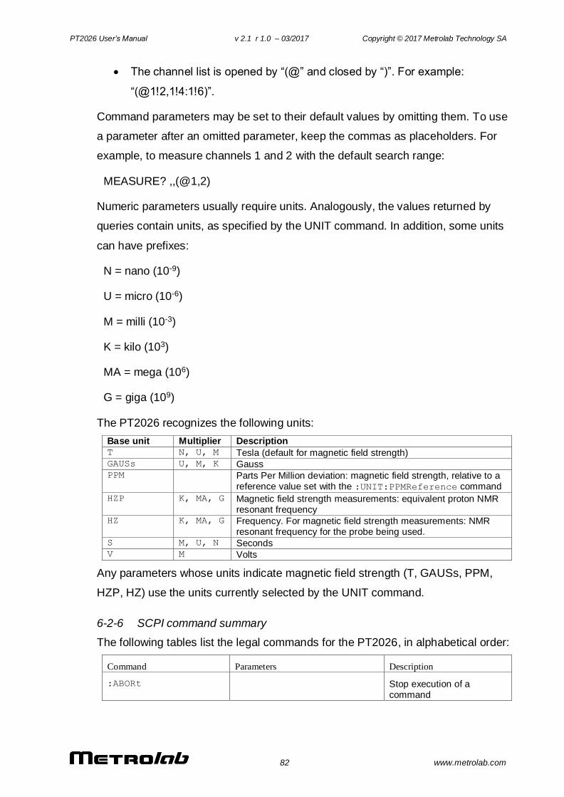
PT2026 User’s Manual v 2.1 r 1.0 – 03/2017 Copyright © 2017 Metrolab Technology SA
82 www.metrolab.com
The channel list is opened by “(@” and closed by “)”. For example:
“(@1!2,1!4:1!6)”.
Command parameters may be set to their default values by omitting them. To use
a parameter after an omitted parameter, keep the commas as placeholders. For
example, to measure channels 1 and 2 with the default search range:
MEASURE? ,,(@1,2)
Numeric parameters usually require units. Analogously, the values returned by
queries contain units, as specified by the UNIT command. In addition, some units
can have prefixes:
N = nano (10-9)
U = micro (10-6)
M = milli (10-3)
K = kilo (103)
MA = mega (106)
G = giga (109)
The PT2026 recognizes the following units:
Base unit Multiplier Description T N, U, M Tesla (default for magnetic field strength) GAUSs U, M, K Gauss PPM Parts Per Million deviation: magnetic field strength, relative to a
reference value set with the :UNIT:PPMReference command
HZP K, MA, G Magnetic field strength measurements: equivalent proton NMR resonant frequency
HZ K, MA, G Frequency. For magnetic field strength measurements: NMR resonant frequency for the probe being used.
S M, U, N Seconds V M Volts
Any parameters whose units indicate magnetic field strength (T, GAUSs, PPM,
HZP, HZ) use the units currently selected by the UNIT command.
6-2-6 SCPI command summary
The following tables list the legal commands for the PT2026, in alphabetical order:
Command Parameters Description
:ABORt Stop execution of a command
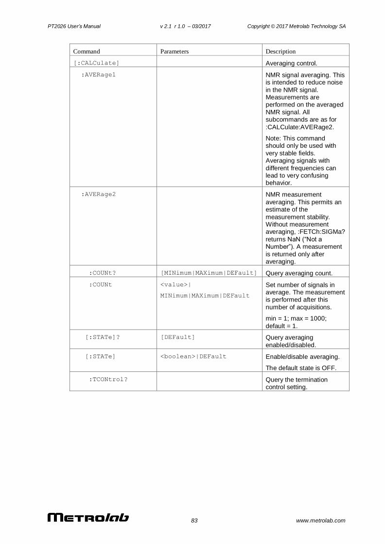
PT2026 User’s Manual v 2.1 r 1.0 – 03/2017 Copyright © 2017 Metrolab Technology SA
83 www.metrolab.com
Command Parameters Description
[:CALCulate] Averaging control.
:AVERage1 NMR signal averaging. This is intended to reduce noise
in the NMR signal. Measurements are performed on the averaged
NMR signal. All subcommands are as for
:CALCulate:AVERage2.
Note: This command should only be used with
very stable fields. Averaging signals with
different frequencies can lead to very confusing behavior.
:AVERage2 NMR measurement
averaging. This permits an estimate of the
measurement stability. Without measurement averaging, :FETCh:SIGMa?
returns NaN (“Not a Number”). A measurement
is returned only after averaging.
:COUNt? [MINimum|MAXimum|DEFault] Query averaging count.
:COUNt <value>|
MINimum|MAXimum|DEFault
Set number of signals in average. The measurement is performed after this
number of acquisitions.
min = 1; max = 1000;
default = 1.
[:STATe]? [DEFault] Query averaging
enabled/disabled.
[:STATe] <boolean>|DEFault Enable/disable averaging.
The default state is OFF.
:TCONtrol? Query the termination control setting.

PT2026 User’s Manual v 2.1 r 1.0 – 03/2017 Copyright © 2017 Metrolab Technology SA
84 www.metrolab.com
:TCONtrol EXPonential|MOVing|REPeat Specify action after
<avg_count> signals:
- EXPonential:
where k = <avg_count>
- MOVing:
Moving window: oldest measurement is subtracted
from average, and newest measurement is added.
This action is not supported for :AVERage1.
- REPeat:
Clear the average and
repeat. This is the default action.
AVGn =1
kXn +
k-1
kAVGn-1
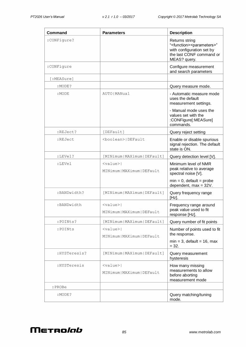
PT2026 User’s Manual v 2.1 r 1.0 – 03/2017 Copyright © 2017 Metrolab Technology SA
85 www.metrolab.com
Command Parameters Description
:CONFigure? Returns string “<function><parameters>”
with configuration set by the last CONF command or
MEAS? query.
:CONFigure Configure measurement
and search parameters
[:MEASure]
:MODE? Query measure mode.
:MODE AUTO|MANual - Automatic measure mode uses the default
measurement settings.
- Manual mode uses the
values set with the :CONFigure[:MEASure] commands.
:REJect? [DEFault] Query reject setting
:REJect <boolean>|DEFault Enable or disable spurious signal rejection. The default
state is ON.
:LEVel? [MINimum|MAXimum|DEFault] Query detection level [V].
:LEVel <value>|
MINimum|MAXimum|DEFault
Minimum level of NMR
peak relative to average spectral noise [V].
min = 0, default = probe dependent, max = 32V.
:BANDwidth? [MINimum|MAXimum|DEFault] Query frequency range [Hz].
:BANDwidth <value>|
MINimum|MAXimum|DEFault
Frequency range around peak value used to fit
response [Hz].
:POINts? [MINimum|MAXimum|DEFault] Query number of fit points
:POINts <value>|
MINimum|MAXimum|DEFault
Number of points used to fit
the response.
min = 3, default = 16, max = 32.
:HYSTeresis? [MINimum|MAXimum|DEFault] Query measurement
hysteresis
:HYSTeresis <value>|
MINimum|MAXimum|DEFault
How many missing
measurements to allow before aborting
measurement mode
:PROBe
:MODE? Query matching/tuning mode.
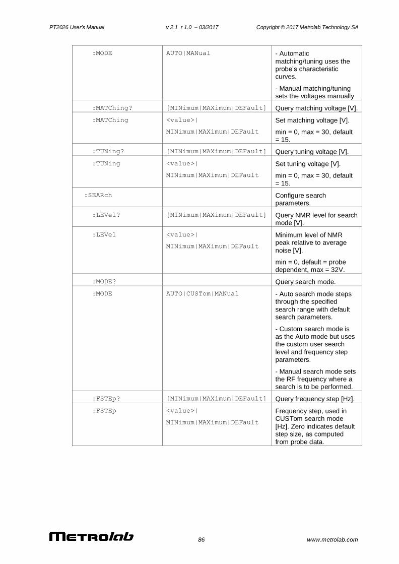
PT2026 User’s Manual v 2.1 r 1.0 – 03/2017 Copyright © 2017 Metrolab Technology SA
86 www.metrolab.com
:MODE AUTO|MANual - Automatic
matching/tuning uses the probe’s characteristic curves.
- Manual matching/tuning sets the voltages manually
:MATChing? [MINimum|MAXimum|DEFault] Query matching voltage [V].
:MATChing <value>|
MINimum|MAXimum|DEFault
Set matching voltage [V].
min = 0, max = 30, default = 15.
:TUNing? [MINimum|MAXimum|DEFault] Query tuning voltage [V].
:TUNing <value>|
MINimum|MAXimum|DEFault
Set tuning voltage [V].
min = 0, max = 30, default
= 15.
:SEARch Configure search parameters.
:LEVel? [MINimum|MAXimum|DEFault] Query NMR level for search mode [V].
:LEVel <value>|
MINimum|MAXimum|DEFault
Minimum level of NMR peak relative to average
noise [V].
min = 0, default = probe dependent, max = 32V.
:MODE? Query search mode.
:MODE AUTO|CUSTom|MANual - Auto search mode steps through the specified
search range with default search parameters.
- Custom search mode is as the Auto mode but uses the custom user search
level and frequency step parameters.
- Manual search mode sets the RF frequency where a search is to be performed.
:FSTEp? [MINimum|MAXimum|DEFault] Query frequency step [Hz].
:FSTEp <value>|
MINimum|MAXimum|DEFault
Frequency step, used in CUSTom search mode
[Hz]. Zero indicates default step size, as computed
from probe data.
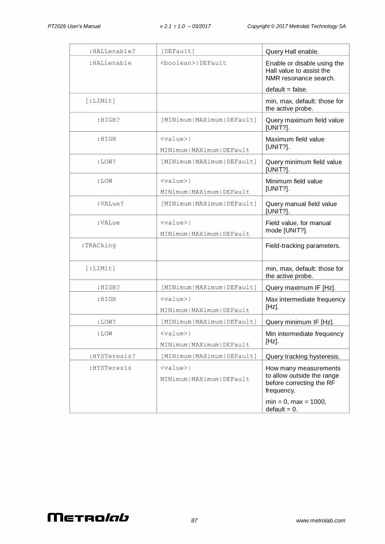
PT2026 User’s Manual v 2.1 r 1.0 – 03/2017 Copyright © 2017 Metrolab Technology SA
87 www.metrolab.com
:HALLenable? [DEFault] Query Hall enable.
:HALLenable <boolean>|DEFault Enable or disable using the Hall value to assist the
NMR resonance search.
default = false.
[:LIMit] min, max, default: those for the active probe.
:HIGH? [MINimum|MAXimum|DEFault] Query maximum field value [UNIT?].
:HIGH <value>|
MINimum|MAXimum|DEFault
Maximum field value
[UNIT?].
:LOW? [MINimum|MAXimum|DEFault] Query minimum field value
[UNIT?].
:LOW <value>|
MINimum|MAXimum|DEFault
Minimum field value [UNIT?].
:VALue? [MINimum|MAXimum|DEFault] Query manual field value [UNIT?].
:VALue <value>|
MINimum|MAXimum|DEFault
Field value, for manual mode [UNIT?].
:TRACking Field-tracking parameters.
[:LIMit] min, max, default: those for the active probe.
:HIGH? [MINimum|MAXimum|DEFault] Query maximum IF [Hz].
:HIGH <value>|
MINimum|MAXimum|DEFault
Max intermediate frequency [Hz].
:LOW? [MINimum|MAXimum|DEFault] Query minimum IF [Hz].
:LOW <value>|
MINimum|MAXimum|DEFault
Min intermediate frequency [Hz].
:HYSTeresis? [MINimum|MAXimum|DEFault] Query tracking hysteresis.
:HYSTeresis <value>|
MINimum|MAXimum|DEFault
How many measurements to allow outside the range before correcting the RF
frequency.
min = 0, max = 1000,
default = 0.
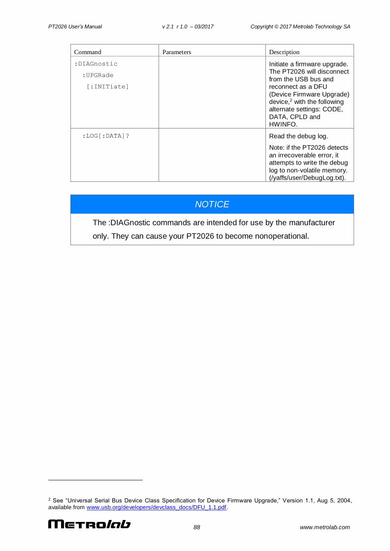
PT2026 User’s Manual v 2.1 r 1.0 – 03/2017 Copyright © 2017 Metrolab Technology SA
88 www.metrolab.com
Command Parameters Description
:DIAGnostic
:UPGRade
[:INITiate]
Initiate a firmware upgrade. The PT2026 will disconnect
from the USB bus and reconnect as a DFU
(Device Firmware Upgrade) device,2 with the following alternate settings: CODE,
DATA, CPLD and HWINFO.
:LOG[:DATA]? Read the debug log.
Note: if the PT2026 detects
an irrecoverable error, it attempts to write the debug
log to non-volatile memory. (/yaffs/user/DebugLog.txt).
NOTICE
The :DIAGnostic commands are intended for use by the manufacturer
only. They can cause your PT2026 to become nonoperational.
2 See “Universal Serial Bus Device Class Specification for Device Firmware Upgrade,” Version 1.1, Aug 5, 2004, available from www.usb.org/developers/devclass_docs/DFU_1.1.pdf.
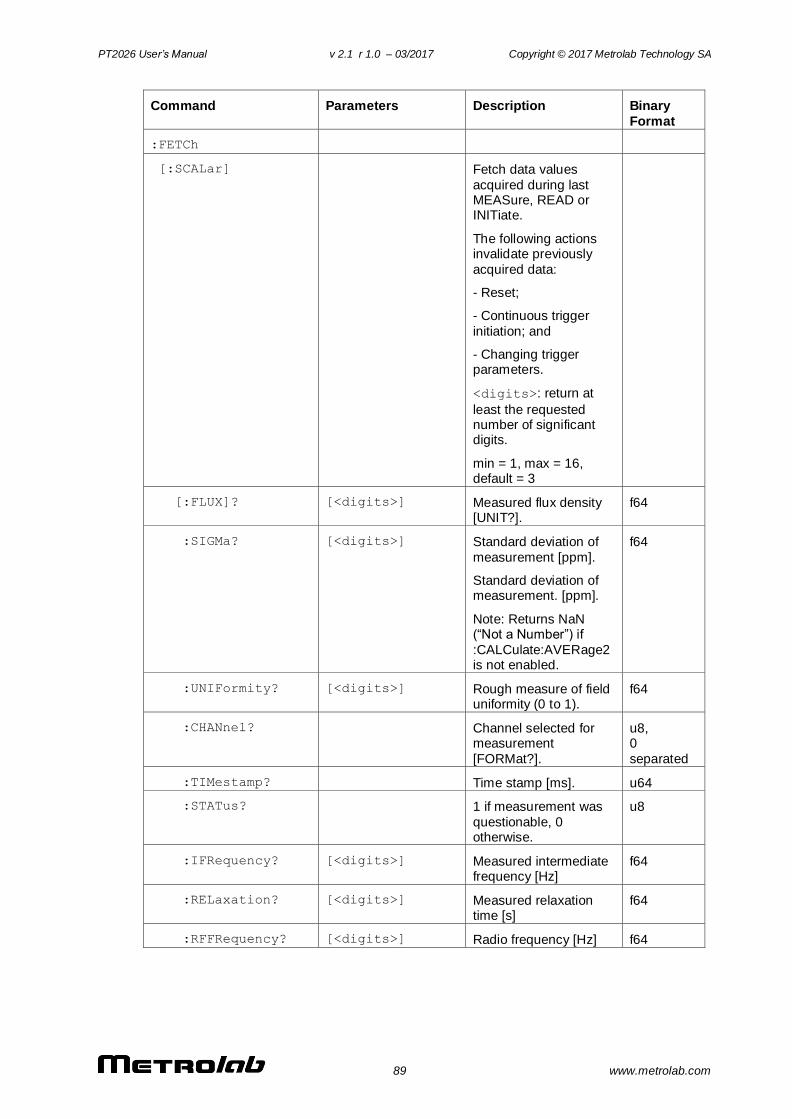
PT2026 User’s Manual v 2.1 r 1.0 – 03/2017 Copyright © 2017 Metrolab Technology SA
89 www.metrolab.com
Command Parameters Description Binary
Format
:FETCh
[:SCALar] Fetch data values
acquired during last MEASure, READ or INITiate.
The following actions invalidate previously
acquired data:
- Reset;
- Continuous trigger
initiation; and
- Changing trigger parameters.
<digits>: return at
least the requested number of significant digits.
min = 1, max = 16, default = 3
[:FLUX]? [<digits>] Measured flux density [UNIT?].
f64
:SIGMa? [<digits>] Standard deviation of
measurement [ppm].
Standard deviation of measurement. [ppm].
Note: Returns NaN (“Not a Number”) if
:CALCulate:AVERage2 is not enabled.
f64
:UNIFormity? [<digits>] Rough measure of field uniformity (0 to 1).
f64
:CHANnel? Channel selected for measurement
[FORMat?].
u8, 0
separated
:TIMestamp? Time stamp [ms]. u64
:STATus? 1 if measurement was
questionable, 0 otherwise.
u8
:IFRequency? [<digits>] Measured intermediate frequency [Hz]
f64
:RELaxation? [<digits>] Measured relaxation time [s]
f64
:RFFRequency? [<digits>] Radio frequency [Hz] f64

PT2026 User’s Manual v 2.1 r 1.0 – 03/2017 Copyright © 2017 Metrolab Technology SA
90 www.metrolab.com
:SPRogress? Search progress:
percentage done, and Hall value if present, -1 otherwise. Only useful
when a search is initiated. [%, UNIT?].
u8, f64
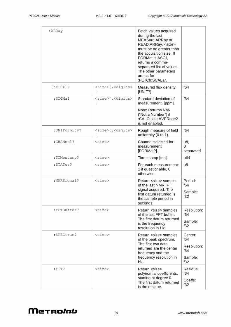
PT2026 User’s Manual v 2.1 r 1.0 – 03/2017 Copyright © 2017 Metrolab Technology SA
91 www.metrolab.com
:ARRay Fetch values acquired
during the last MEASure:ARRay or READ:ARRay. <size>
must be no greater than the acquisition size. If
FORMat is ASCii, returns a comma-
separated list of values. The other parameters are as for
:FETCh:SCALar.
[:FLUX]? <size>[,<digits>
]
Measured flux density [UNIT?].
f64
:SIGMa? <size>[,<digits>
]
Standard deviation of measurement. [ppm].
Note: Returns NaN (“Not a Number”) if :CALCulate:AVERage2
is not enabled.
f64
:UNIFormity? <size>[,<digits>
] Rough measure of field uniformity (0 to 1).
f64
:CHANnel? <size> Channel selected for measurement
[FORMat?].
u8, 0
separated
:TIMestamp? <size> Time stamp [ms]. u64
:STATus? <size> For each measurement: 1 if questionable, 0
otherwise.
u8
:NMRSignal? <size> Return <size> samples of the last NMR IF signal acquired. The
first datum returned is the sample period in
seconds.
Period: f64
Sample:
f32
:FFTBuffer? <size> Return <size> samples of the last FFT buffer. The first datum returned
is the frequency resolution in Hz.
Resolution: f64
Sample:
f32
:SPECtrum? <size> Return <size> samples of the peak spectrum.
The first two data returned are the center
frequency and the frequency resolution in Hz.
Center: f64
Resolution: f64
Sample:
f32
:FIT? <size> Return <size> polynomial coefficients, starting at degree 0.
The first datum returned is the residue.
Residue: f64
Coeffs:
f32

PT2026 User’s Manual v 2.1 r 1.0 – 03/2017 Copyright © 2017 Metrolab Technology SA
92 www.metrolab.com
Command Parameters Description
:FORMat
[:DATA]? Query data output format
[:DATA] ASCii|INTeger Set format for returned data.
ASCii by default.
INTeger returns an IEEE488.2 definite-length block, consisting of an 8-
byte header of the form “#6nnnnnn” and followed by
nnnnnn bytes of binary data.
For the flux density and
standard deviation, binary data consists of 64-bit little-
endian floating-point values.
The binary representation
of a channel is a 16-bit little-endian unsigned
integer, with channel numbers as defined in
Section 6-3-2. The relevant commands are flagged with “[FORMat?]”.
The binary representation of a timestamp is a 64-bit
unsigned integer [ms].
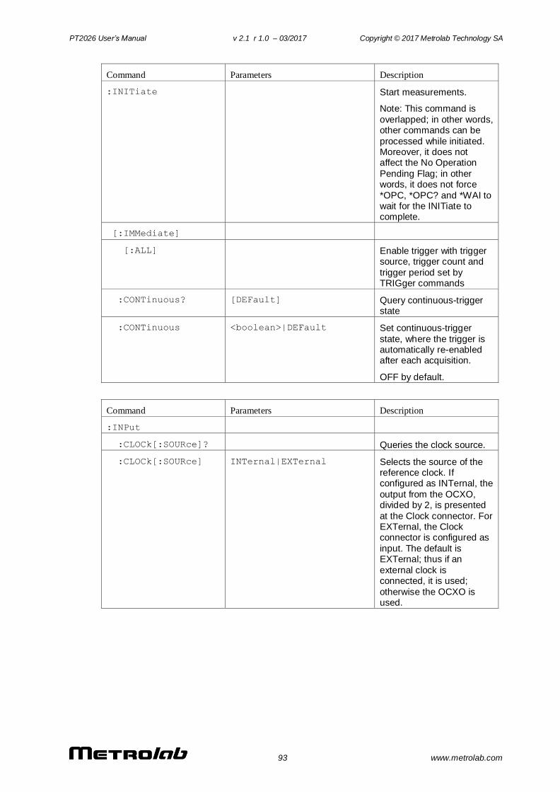
PT2026 User’s Manual v 2.1 r 1.0 – 03/2017 Copyright © 2017 Metrolab Technology SA
93 www.metrolab.com
Command Parameters Description
:INITiate Start measurements.
Note: This command is
overlapped; in other words, other commands can be
processed while initiated. Moreover, it does not affect the No Operation
Pending Flag; in other words, it does not force
*OPC, *OPC? and *WAI to wait for the INITiate to complete.
[:IMMediate]
[:ALL] Enable trigger with trigger source, trigger count and
trigger period set by TRIGger commands
:CONTinuous? [DEFault] Query continuous-trigger state
:CONTinuous <boolean>|DEFault Set continuous-trigger
state, where the trigger is automatically re-enabled after each acquisition.
OFF by default.
Command Parameters Description
:INPut
:CLOCk[:SOURce]? Queries the clock source.
:CLOCk[:SOURce] INTernal|EXTernal Selects the source of the reference clock. If configured as INTernal, the
output from the OCXO, divided by 2, is presented
at the Clock connector. For EXTernal, the Clock connector is configured as
input. The default is EXTernal; thus if an
external clock is connected, it is used;
otherwise the OCXO is used.
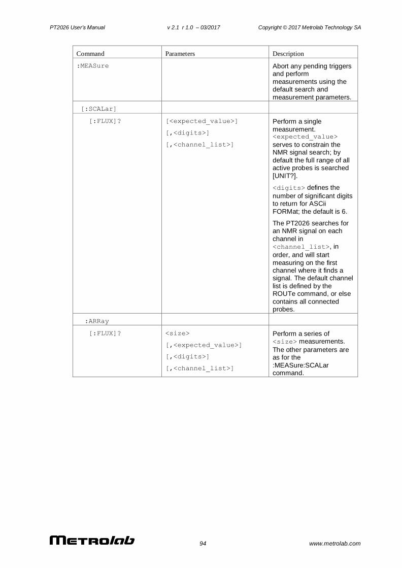
PT2026 User’s Manual v 2.1 r 1.0 – 03/2017 Copyright © 2017 Metrolab Technology SA
94 www.metrolab.com
Command Parameters Description
:MEASure Abort any pending triggers and perform
measurements using the default search and
measurement parameters.
[:SCALar]
[:FLUX]? [<expected_value>]
[,<digits>]
[,<channel_list>]
Perform a single
measurement. <expected_value>
serves to constrain the NMR signal search; by
default the full range of all active probes is searched
[UNIT?].
<digits> defines the
number of significant digits to return for ASCii
FORMat; the default is 6.
The PT2026 searches for an NMR signal on each
channel in <channel_list>, in
order, and will start
measuring on the first channel where it finds a signal. The default channel
list is defined by the ROUTe command, or else
contains all connected probes.
:ARRay
[:FLUX]? <size>
[,<expected_value>]
[,<digits>]
[,<channel_list>]
Perform a series of <size> measurements.
The other parameters are as for the
:MEASure:SCALar command.
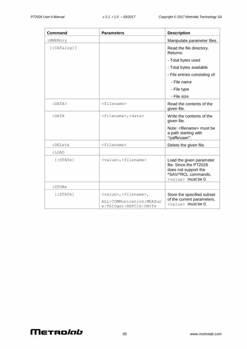
PT2026 User’s Manual v 2.1 r 1.0 – 03/2017 Copyright © 2017 Metrolab Technology SA
95 www.metrolab.com
Command Parameters Description
:MMEMory Manipulate parameter files.
[:CATalog]? Read the file directory. Returns:
- Total bytes used
- Total bytes available
- File entries consisting of:
- File name
- File type
- File size
:DATA? <filename> Read the contents of the given file.
:DATA <filename>,<data> Write the contents of the given file.
Note: <filename> must be a path starting with
“/yaffs/user/”.
:DELete <filename> Delete the given file.
:LOAD
[:STATe] <value>,<filename> Load the given parameter file. Since the PT2026
does not support the *SAV/*RCL commands,
<value> must be 0.
:STORe
[:STATe] <value>,<filename>,
ALL|COMMunication|MEASur
e|TRIGger|REFClk|UNITs
Store the specified subset of the current parameters. <value> must be 0.
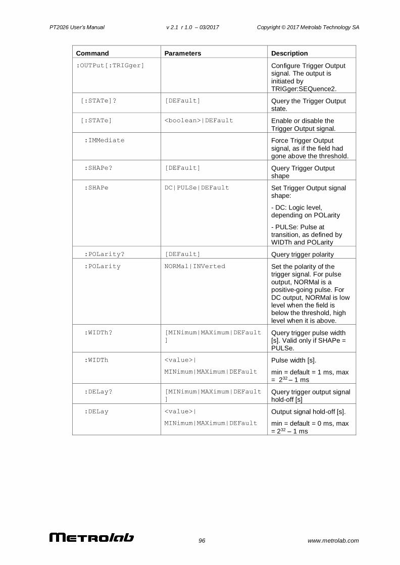
PT2026 User’s Manual v 2.1 r 1.0 – 03/2017 Copyright © 2017 Metrolab Technology SA
96 www.metrolab.com
Command Parameters Description
:OUTPut[:TRIGger] Configure Trigger Output signal. The output is
initiated by TRIGger:SEQuence2.
[:STATe]? [DEFault] Query the Trigger Output state.
[:STATe] <boolean>|DEFault Enable or disable the
Trigger Output signal.
:IMMediate Force Trigger Output
signal, as if the field had gone above the threshold.
:SHAPe? [DEFault] Query Trigger Output shape
:SHAPe DC|PULSe|DEFault Set Trigger Output signal shape:
- DC: Logic level, depending on POLarity
- PULSe: Pulse at transition, as defined by WIDTh and POLarity
:POLarity? [DEFault] Query trigger polarity
:POLarity NORMal|INVerted Set the polarity of the trigger signal. For pulse
output, NORMal is a positive-going pulse. For
DC output, NORMal is low level when the field is below the threshold, high
level when it is above.
:WIDTh? [MINimum|MAXimum|DEFault
]
Query trigger pulse width [s]. Valid only if SHAPe = PULSe.
:WIDTh <value>|
MINimum|MAXimum|DEFault
Pulse width [s].
min = default = 1 ms, max = 232 – 1 ms
:DELay? [MINimum|MAXimum|DEFault
]
Query trigger output signal hold-off [s]
:DELay <value>|
MINimum|MAXimum|DEFault
Output signal hold-off [s].
min = default = 0 ms, max
= 232 – 1 ms

PT2026 User’s Manual v 2.1 r 1.0 – 03/2017 Copyright © 2017 Metrolab Technology SA
97 www.metrolab.com
Command Parameters Description
:READ Abort any pending triggers and perform
measurements using the current search,
measurement and routing parameters.
[:SCALar]
[:FLUX]? [<expected_value>]
[,<digits>]
[,<channel_list>]
Perform a single measurement. <expected_value>
serves to constrain the
NMR signal search; by default the full range of all
active probes is searched [UNIT?].
<digits> defines the
number of significant digits
to return for ASCii FORMat; the default is 6.
The PT2026 searches for an NMR signal on each channel in
<channel_list>, in
order, and will start measuring on the first channel where it finds a
signal. The default channel list is defined by the
ROUTe command, or else contains all connected
probes.
:ARRay
[:FLUX]? <size>
[,<expected_value>]
[,<digits>]
[,<channel_list>]
Perform a series of <size> measurements.
The other parameters are
as for the :READ:SCALar command.
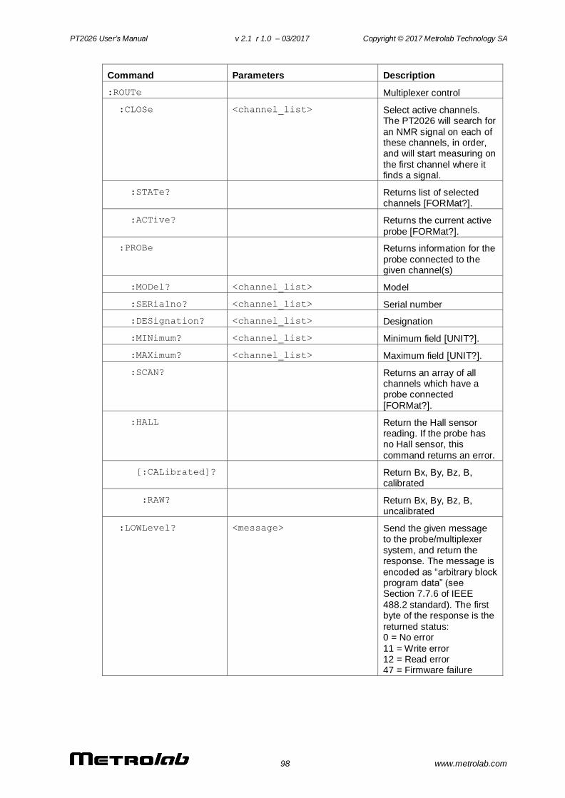
PT2026 User’s Manual v 2.1 r 1.0 – 03/2017 Copyright © 2017 Metrolab Technology SA
98 www.metrolab.com
Command Parameters Description
:ROUTe Multiplexer control
:CLOSe <channel_list> Select active channels. The PT2026 will search for
an NMR signal on each of these channels, in order, and will start measuring on
the first channel where it finds a signal.
:STATe? Returns list of selected channels [FORMat?].
:ACTive? Returns the current active
probe [FORMat?].
:PROBe Returns information for the
probe connected to the given channel(s)
:MODel? <channel_list> Model
:SERialno? <channel_list> Serial number
:DESignation? <channel_list> Designation
:MINimum? <channel_list> Minimum field [UNIT?].
:MAXimum? <channel_list> Maximum field [UNIT?].
:SCAN? Returns an array of all channels which have a probe connected
[FORMat?].
:HALL Return the Hall sensor reading. If the probe has no Hall sensor, this
command returns an error.
[:CALibrated]? Return Bx, By, Bz, B, calibrated
:RAW? Return Bx, By, Bz, B, uncalibrated
:LOWLevel? <message> Send the given message to the probe/multiplexer
system, and return the response. The message is
encoded as “arbitrary block program data” (see Section 7.7.6 of IEEE
488.2 standard). The first byte of the response is the
returned status: 0 = No error
11 = Write error 12 = Read error 47 = Firmware failure
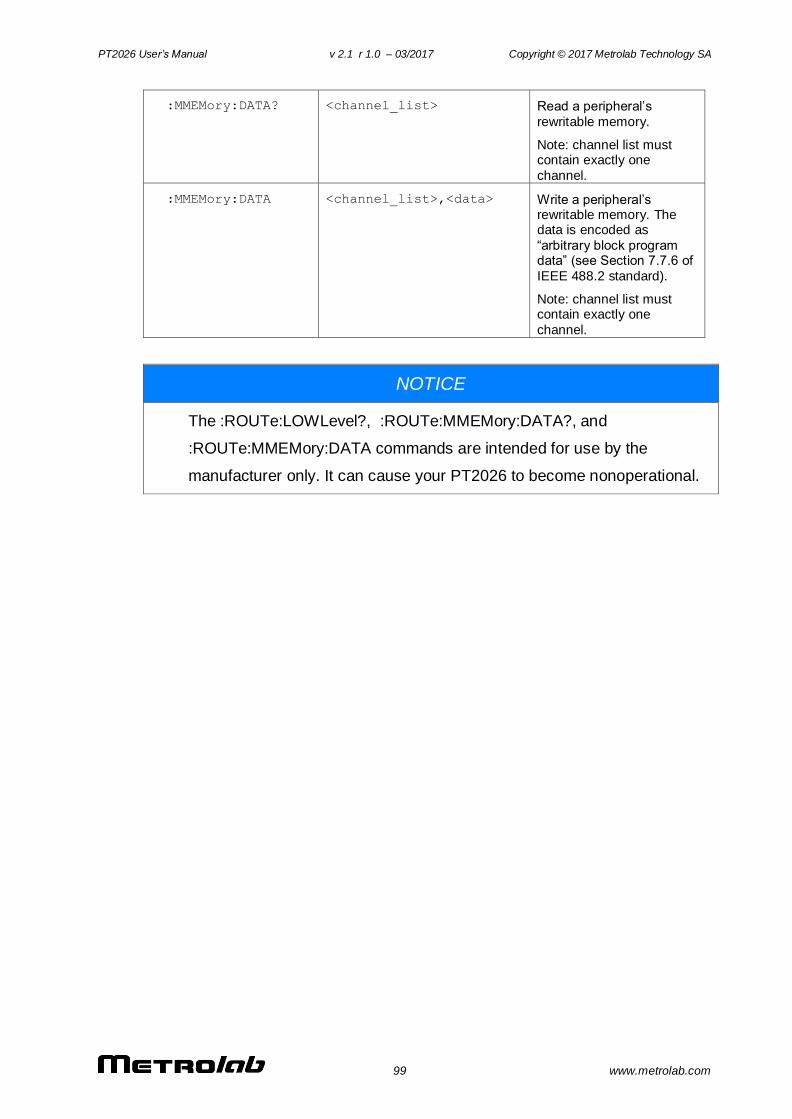
PT2026 User’s Manual v 2.1 r 1.0 – 03/2017 Copyright © 2017 Metrolab Technology SA
99 www.metrolab.com
:MMEMory:DATA? <channel_list> Read a peripheral’s
rewritable memory.
Note: channel list must contain exactly one
channel.
:MMEMory:DATA <channel_list>,<data> Write a peripheral’s rewritable memory. The data is encoded as
“arbitrary block program data” (see Section 7.7.6 of
IEEE 488.2 standard).
Note: channel list must contain exactly one
channel.
NOTICE
The :ROUTe:LOWLevel?, :ROUTe:MMEMory:DATA?, and
:ROUTe:MMEMory:DATA commands are intended for use by the
manufacturer only. It can cause your PT2026 to become nonoperational.
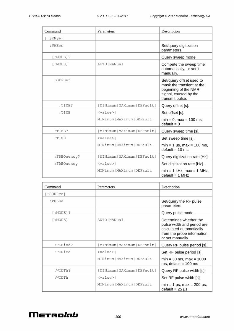
PT2026 User’s Manual v 2.1 r 1.0 – 03/2017 Copyright © 2017 Metrolab Technology SA
100 www.metrolab.com
Command Parameters Description
[:SENSe]
:SWEep Set/query digitization parameters
[:MODE]? Query sweep mode
[:MODE] AUTO|MANual Compute the sweep time automatically, or set it manually.
:OFFSet Set/query offset used to
mask the transient at the beginning of the NMR signal, caused by the
transmit pulse.
:TIME? [MINimum|MAXimum|DEFault] Query offset [s].
:TIME <value>|
MINimum|MAXimum|DEFault
Set offset [s].
min = 0, max = 100 ms, default = 0
:TIME? [MINimum|MAXimum|DEFault] Query sweep time [s].
:TIME <value>|
MINimum|MAXimum|DEFault
Set sweep time [s].
min = 1 µs, max = 100 ms, default = 10 ms
:FREQuency? [MINimum|MAXimum|DEFault] Query digitization rate [Hz].
:FREQuency <value>|
MINimum|MAXimum|DEFault
Set digitization rate [Hz].
min = 1 kHz, max = 1 MHz,
default = 1 MHz
Command Parameters Description
[:SOURce]
:PULSe Set/query the RF pulse parameters
[:MODE]? Query pulse mode.
[:MODE] AUTO|MANual Determines whether the pulse width and period are calculated automatically
from the probe information, or set manually.
:PERiod? [MINimum|MAXimum|DEFault] Query RF pulse period [s].
:PERiod <value>|
MINimum|MAXimum|DEFault
Set RF pulse period [s].
min = 30 ms, max = 1000
ms, default = 100 ms
:WIDTh? [MINimum|MAXimum|DEFault] Query RF pulse width [s].
:WIDTh <value>|
MINimum|MAXimum|DEFault
Set RF pulse width [s].
min = 1 µs, max = 200 µs,
default = 25 µs
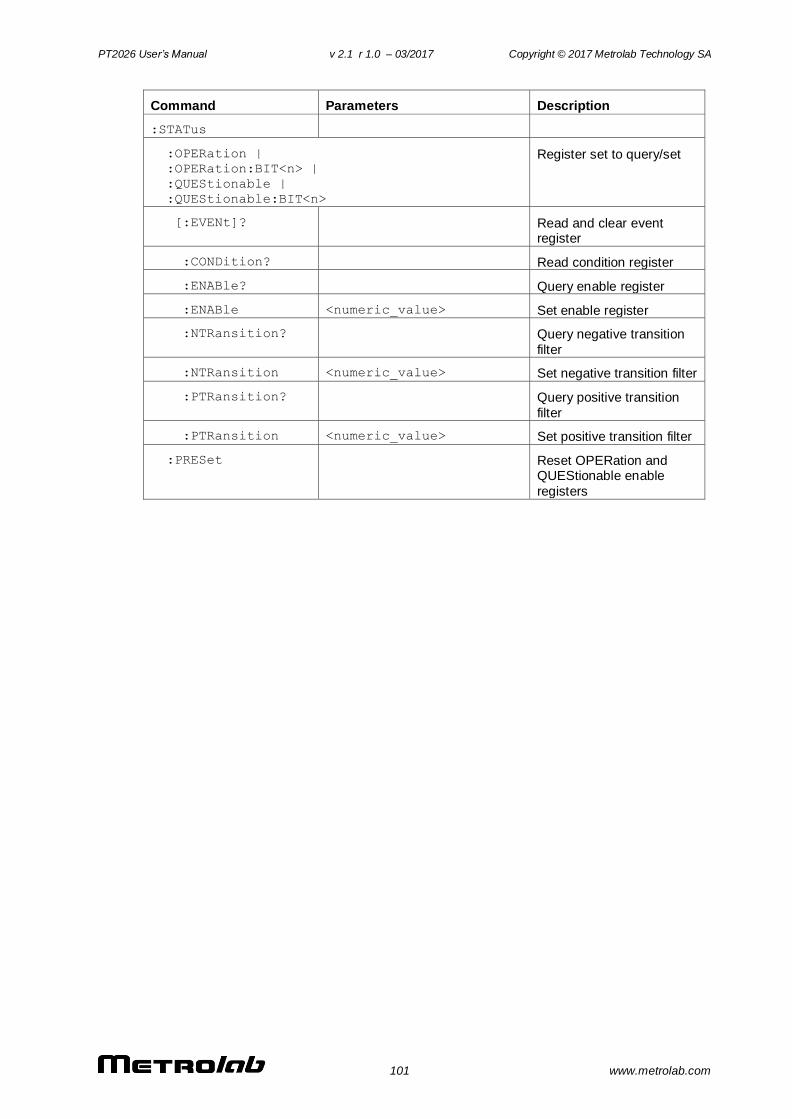
PT2026 User’s Manual v 2.1 r 1.0 – 03/2017 Copyright © 2017 Metrolab Technology SA
101 www.metrolab.com
Command Parameters Description
:STATus
:OPERation |
:OPERation:BIT<n> |
:QUEStionable |
:QUEStionable:BIT<n>
Register set to query/set
[:EVENt]? Read and clear event register
:CONDition? Read condition register
:ENABle? Query enable register
:ENABle <numeric_value> Set enable register
:NTRansition? Query negative transition
filter
:NTRansition <numeric_value> Set negative transition filter
:PTRansition? Query positive transition
filter
:PTRansition <numeric_value> Set positive transition filter
:PRESet Reset OPERation and QUEStionable enable
registers
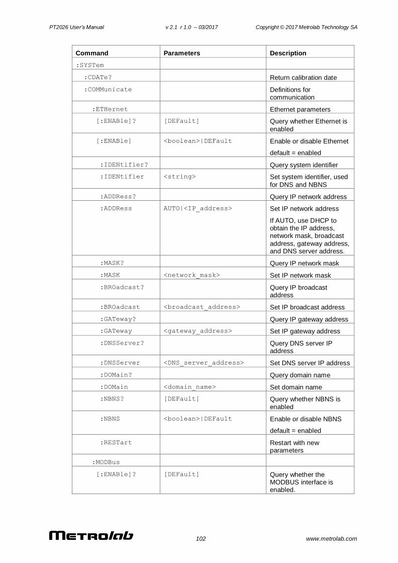
PT2026 User’s Manual v 2.1 r 1.0 – 03/2017 Copyright © 2017 Metrolab Technology SA
102 www.metrolab.com
Command Parameters Description
:SYSTem
:CDATe? Return calibration date
:COMMunicate Definitions for communication
:ETHernet Ethernet parameters
[:ENABle]? [DEFault] Query whether Ethernet is
enabled
[:ENABle] <boolean>|DEFault Enable or disable Ethernet
default = enabled
:IDENtifier? Query system identifier
:IDENtifier <string> Set system identifier, used
for DNS and NBNS
:ADDRess? Query IP network address
:ADDRess AUTO|<IP_address> Set IP network address
If AUTO, use DHCP to obtain the IP address, network mask, broadcast
address, gateway address, and DNS server address.
:MASK? Query IP network mask
:MASK <network_mask> Set IP network mask
:BROadcast? Query IP broadcast address
:BROadcast <broadcast_address> Set IP broadcast address
:GATeway? Query IP gateway address
:GATeway <gateway_address> Set IP gateway address
:DNSServer? Query DNS server IP address
:DNSServer <DNS_server_address> Set DNS server IP address
:DOMain? Query domain name
:DOMain <domain_name> Set domain name
:NBNS? [DEFault] Query whether NBNS is
enabled
:NBNS <boolean>|DEFault Enable or disable NBNS
default = enabled
:RESTart Restart with new parameters
:MODBus
[:ENABle]? [DEFault] Query whether the MODBUS interface is enabled.
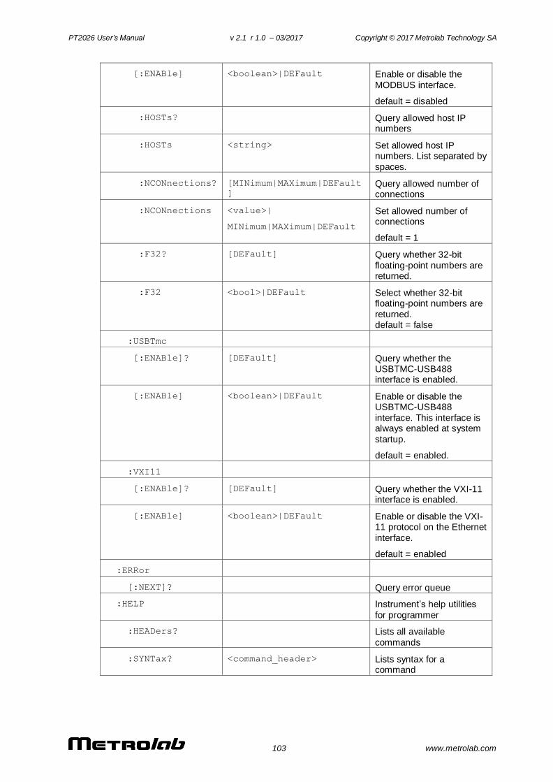
PT2026 User’s Manual v 2.1 r 1.0 – 03/2017 Copyright © 2017 Metrolab Technology SA
103 www.metrolab.com
[:ENABle] <boolean>|DEFault Enable or disable the
MODBUS interface.
default = disabled
:HOSTs? Query allowed host IP numbers
:HOSTs <string> Set allowed host IP numbers. List separated by
spaces.
:NCONnections? [MINimum|MAXimum|DEFault
] Query allowed number of connections
:NCONnections <value>|
MINimum|MAXimum|DEFault
Set allowed number of connections
default = 1
:F32? [DEFault] Query whether 32-bit
floating-point numbers are returned.
:F32 <bool>|DEFault Select whether 32-bit floating-point numbers are
returned. default = false
:USBTmc
[:ENABle]? [DEFault] Query whether the USBTMC-USB488 interface is enabled.
[:ENABle] <boolean>|DEFault Enable or disable the USBTMC-USB488
interface. This interface is always enabled at system
startup.
default = enabled.
:VXI11
[:ENABle]? [DEFault] Query whether the VXI-11 interface is enabled.
[:ENABle] <boolean>|DEFault Enable or disable the VXI-11 protocol on the Ethernet
interface.
default = enabled
:ERRor
[:NEXT]? Query error queue
:HELP Instrument’s help utilities
for programmer
:HEADers? Lists all available
commands
:SYNTax? <command_header> Lists syntax for a command
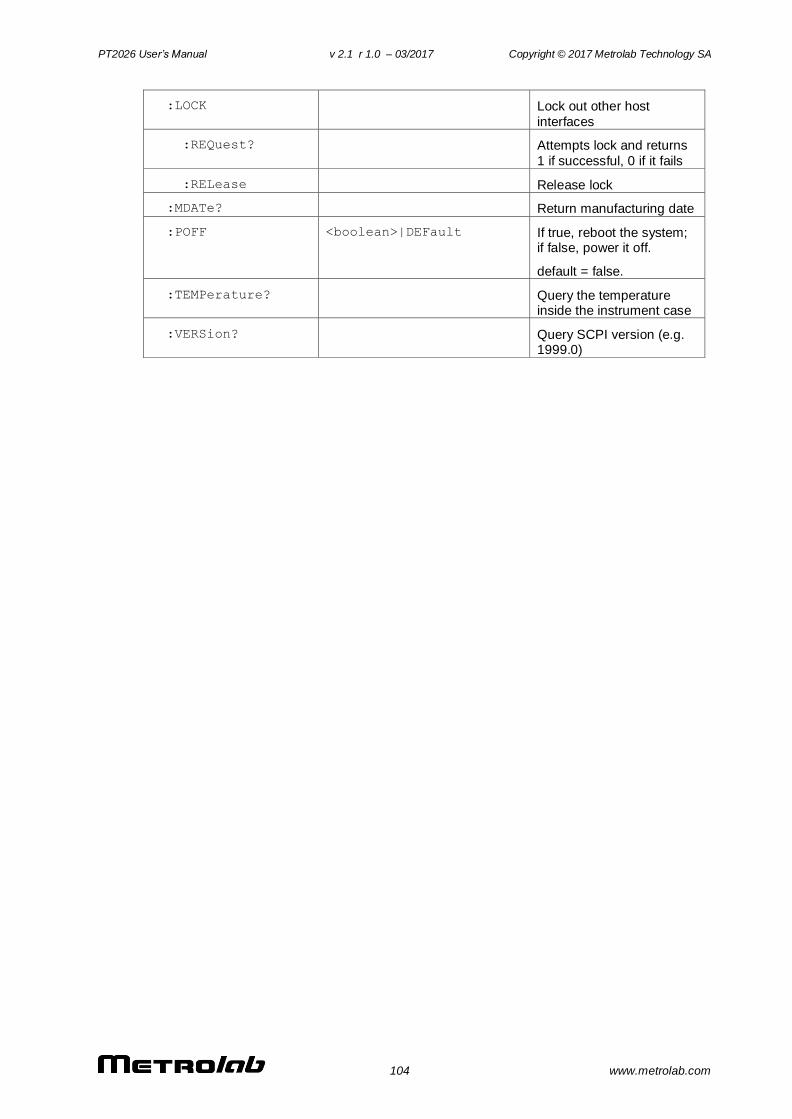
PT2026 User’s Manual v 2.1 r 1.0 – 03/2017 Copyright © 2017 Metrolab Technology SA
104 www.metrolab.com
:LOCK Lock out other host
interfaces
:REQuest? Attempts lock and returns
1 if successful, 0 if it fails
:RELease Release lock
:MDATe? Return manufacturing date
:POFF <boolean>|DEFault If true, reboot the system; if false, power it off.
default = false.
:TEMPerature? Query the temperature inside the instrument case
:VERSion? Query SCPI version (e.g. 1999.0)
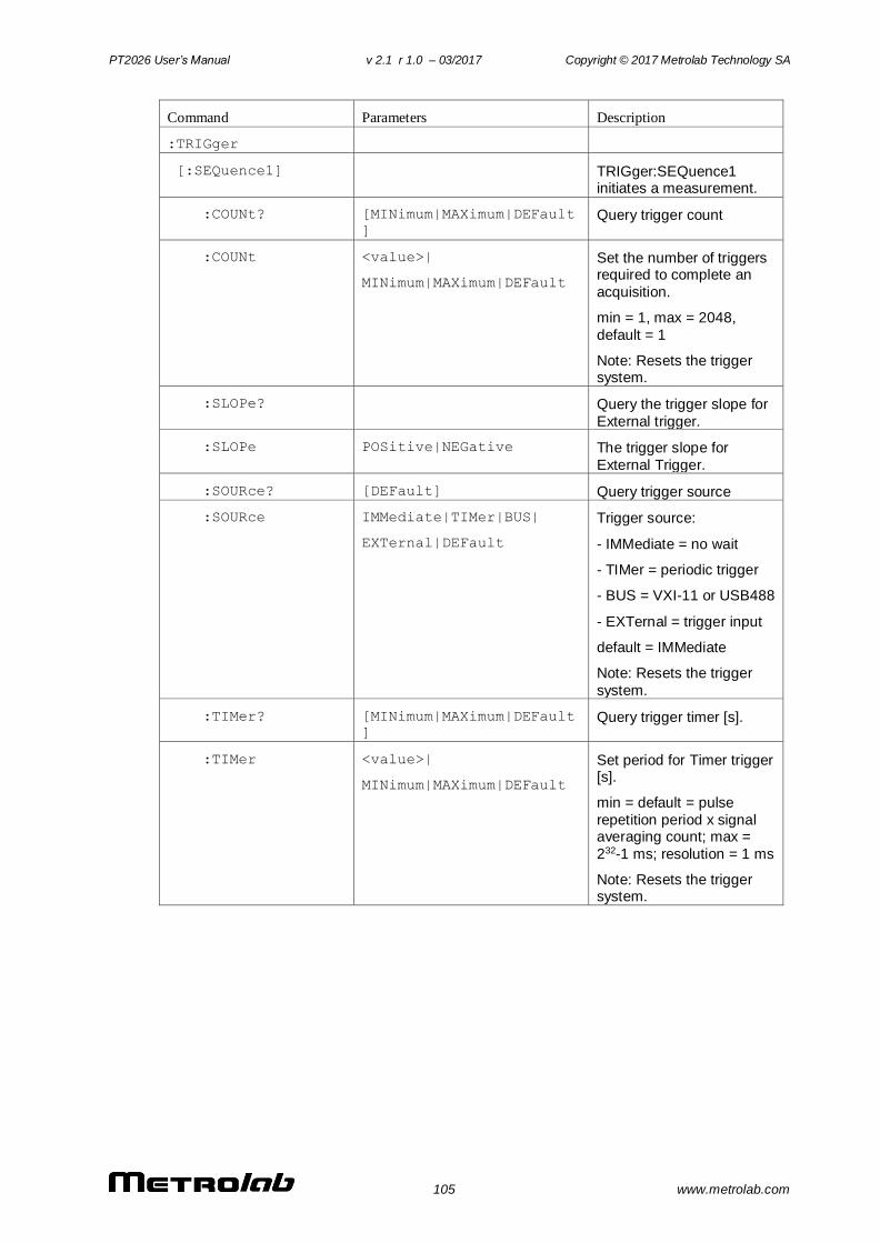
PT2026 User’s Manual v 2.1 r 1.0 – 03/2017 Copyright © 2017 Metrolab Technology SA
105 www.metrolab.com
Command Parameters Description
:TRIGger
[:SEQuence1] TRIGger:SEQuence1 initiates a measurement.
:COUNt? [MINimum|MAXimum|DEFault
]
Query trigger count
:COUNt <value>|
MINimum|MAXimum|DEFault
Set the number of triggers required to complete an
acquisition.
min = 1, max = 2048,
default = 1
Note: Resets the trigger system.
:SLOPe? Query the trigger slope for
External trigger.
:SLOPe POSitive|NEGative The trigger slope for
External Trigger.
:SOURce? [DEFault] Query trigger source
:SOURce IMMediate|TIMer|BUS|
EXTernal|DEFault
Trigger source:
- IMMediate = no wait
- TIMer = periodic trigger
- BUS = VXI-11 or USB488
- EXTernal = trigger input
default = IMMediate
Note: Resets the trigger
system.
:TIMer? [MINimum|MAXimum|DEFault
] Query trigger timer [s].
:TIMer <value>|
MINimum|MAXimum|DEFault
Set period for Timer trigger [s].
min = default = pulse
repetition period x signal averaging count; max =
232-1 ms; resolution = 1 ms
Note: Resets the trigger system.
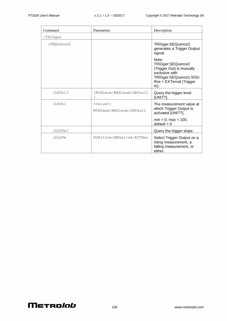
PT2026 User’s Manual v 2.1 r 1.0 – 03/2017 Copyright © 2017 Metrolab Technology SA
106 www.metrolab.com
Command Parameters Description
:TRIGger
:SEQuence2 TRIGger:SEQuence2 generates a Trigger Output
signal.
Note: TRIGger:SEQuence2
(Trigger Out) is mutually exclusive with
TRIGger:SEQuence1:SOURce = EXTernal (Trigger In).
:LEVel? [MINimum|MAXimum|DEFault
]
Query the trigger level
[UNIT?].
:LEVel <value>|
MINimum|MAXimum|DEFault
The measurement value at
which Trigger Output is activated [UNIT?].
min = 0, max = 100, default = 0
:SLOPe? Query the trigger slope.
:SLOPe POSitive|NEGative|EITHer Select Trigger Output on a
rising measurement, a falling measurement, or
either.
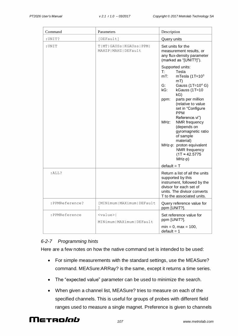
PT2026 User’s Manual v 2.1 r 1.0 – 03/2017 Copyright © 2017 Metrolab Technology SA
107 www.metrolab.com
Command Parameters Description
:UNIT? [DEFault] Query units
:UNIT T|MT|GAUSs|KGAUss|PPM|
MAHZP|MAHZ|DEFault
Set units for the measurement results, or
any flux-density parameter (marked as “[UNIT?]”).
Supported units:
T: Tesla mT: mTesla (1T=103
mT) G: Gauss (1T=104 G) kG: kGauss (1T=10
kG) ppm: parts per million
(relative to value set in “Configure PPM
Reference.vi”) MHz: NMR frequency
(depends on gyromagnetic ratio
of sample material)
MHz-p: proton equivalent
NMR frequency (1T ≈ 42.5775
MHz-p)
default = T
:ALL? Return a list of all the units supported by this
instrument, followed by the divisor for each set of units. The divisor converts
T to the associated units.
:PPMReference? [MINimum|MAXimum|DEFault
]
Query reference value for ppm [UNIT?].
:PPMReference <value>|
MINimum|MAXimum|DEFault
Set reference value for ppm [UNIT?].
min = 0, max = 100, default = 1
6-2-7 Programming hints
Here are a few notes on how the native command set is intended to be used:
For simple measurements with the standard settings, use the MEASure?
command. MEASure:ARRay? is the same, except it returns a time series.
The “expected value” parameter can be used to minimize the search.
When given a channel list, MEASure? tries to measure on each of the
specified channels. This is useful for groups of probes with different field
ranges used to measure a single magnet. Preference is given to channels
PT2026 User’s Manual v 2.1 r 1.0 – 03/2017 Copyright © 2017 Metrolab Technology SA
108 www.metrolab.com
with previous successful measurements, and the result from the first
channel with a successful measurement is returned. Use
:FETCh:CHANnel? to know which channel was measured.
Use the UNIT command to set the units in which the results are returned,
and the “digits” parameter to control the number of significant figures
returned (assuming FORMat is ASCii).
For measurements with non-standard parameters, do a CONFigure, INPut,
ROUTe, SWEep, SOURce and/or PULSe, followed by a READ. As with
MEASure, READ:ARRay? returns a time series. The optional parameters
act as for MEASure.
Use the TRIGger:SEQuence1 commands to control the measurement
timing. As trigger source, you can select “IMMediate”, an internal timer, a
trigger command sent from the host, or an external Trigger In signal. After
setting up the trigger source, you initiate a measurement using the INITiate
command. The CONTinuous option immediately re-initiates an acquisition
when the previous one has completed.
Use the :CALCulate:AVERage commands to control averaging. The
PT2026 supports averaging of the NMR signal, or averaging of the
resulting measurement. Any combination of signal- and measurement
averaging is supported. Averaging is only effective for a stable field.
The measurement integration time depends on the trigger and the
measurement averaging options:
If CALCulate:AVERage2:TCONtrol = REPeat, the measurement average is
computed from a block of new measurements initiated by the trigger.
Otherwise, for EXPonential and MOVing mode averaging, the average is
computed from one new measurement, initiated by the trigger, plus older
measurements that have been acquired in the course of signal tracking
(and may never have been returned to the user).
Use the :OUTPut[:TRIGger] commands to configure an output trigger
signal when the measured field value crosses a certain threshold. Use the
TRIGger:SEQuence2 commands to initiate the output trigger. Note that the
PT2026 User’s Manual v 2.1 r 1.0 – 03/2017 Copyright © 2017 Metrolab Technology SA
109 www.metrolab.com
Trigger In function (TRIGger:SEQuence1:SOURce = EXTernal) is mutually
exclusive with the Trigger Out function.
Use the FETCh command to retrieve all data corresponding to a preceding
MEASure?, READ? or INITiate command, or FETCh:ARRay for the data
corresponding to a MEASure:ARRay?, READ:ARRay? or INITiate with
TRIGger:COUNt > 1. The NMR signal and intermediate signal analysis
results corresponding to the last measurement can be retrieved with the
FETCh:ARRay:NMRSignal? / FFTBuffer? / SPECtrum? / FIT? commands.
The ROUTe:CLOSe command does the same thing as the channel list in
the MEASure and READ commands. The syntax of the channel list is
specified by Volume 1 of the SCPI standard, Section 8.3.2. For example,
ROUTe:CLOSe (@1) selects channel 1, and ROUTe:CLOSe (@2!3)
selects channel 3 on a secondary mux attached to channel 2 of the primary
mux. Colons are used for ranges of channels; for example, ROUTe:CLOSe
(@3:5) sets up to measure channel 3, 4 or 5. Commas are used to
enumerate several channels or channel ranges; for example,
ROUTe:CLOSe (@1,2) sets up to measure channel 1 or channel 2.
Use ROUTe:SCAN? to find all channels with a probe attached. Use
ROUTe:PROBe to retrieve information about a probe.
To determine whether an NMR signal has been found, check the
OPERation status register. By setting the appropriate Operation Status
Enable bit, plus the OSB (Operation Summary Bit) in the Status Enable
register, you can generate a ReQuest for Service (RQS) when the PT2026
enters a given state.
Using the *OPC command, you can also generate a ReQuest for Service
(RQS) when a measurement (or any other action) is complete. Set bit 0 of
the Standard Event Enable register and the ESB (Event Summary Bit) in
the Status Enable register. Now, the execution of an *OPC command will
generate an RQS.
Be sure to check the status after every command. The Standard Event
Status register provides a general idea of what went wrong, and the
message on the Error/Event Queue (retrieved by SYSTem:ERRor?)
PT2026 User’s Manual v 2.1 r 1.0 – 03/2017 Copyright © 2017 Metrolab Technology SA
110 www.metrolab.com
provides a detailed diagnostic. See Section 6-2-8 for the exact
interpretation of these error messages. It may be convenient to set up the
Enable bits to generate a ReQuest for Service (RQS) when an error is
encountered.
On the USBTMC host interface, if you program the instrument to generate
an RQS, it is very important to Enable Service Requests on the host. This
posts a read on the appropriate USB endpoint, the Interrupt endpoint. In
the USB protocol, the host initiates all transfers; so if the host has not
posted a read, the instrument cannot complete its RQS transfer. This will
block the Interrupt endpoint, and any other commands using this endpoint
– notably the USBTMC-USB488 Read Status Byte function – will fail.
The MMEMory commands are used to manipulate XML-format parameter
files. The user can store custom parameters – e.g. user-friendly channel
names – that they would like to store with the instrument.
Two host interfaces can be synchronized using the
STATus:OPERation:BIT11 register. Enable the bits of interest in
STATus:OPERation:BIT11, bit 11 in STATus:OPERation, and the OSB in
the Status Byte; now, a Service Request (SRQ) will be generated
whenever the configuration of one of the corresponding subsystems
changes. The application must then read STATus:OPERation:BIT11 to
identify which subsystem is affected. Finally, the updated value of these
parameters can be read back using the appropriate query. Note that since
reading the STATus:OPERation:BIT11 register also resets it, this technique
does not work for more than two host interfaces.
6-2-8 Error codes
Error codes returned by the native host interfaces are numbered according to the
SCPI standard. Sections 21.8.9 through 21.8.16 of Volume 2 of the SCPI manual,
“Command Reference”, provide a generic description of all possible error codes.
In general, the codes are between -800 and 300. This chapter describes only the
error codes produced by the PT2026, and the circumstances that might produce
each error.
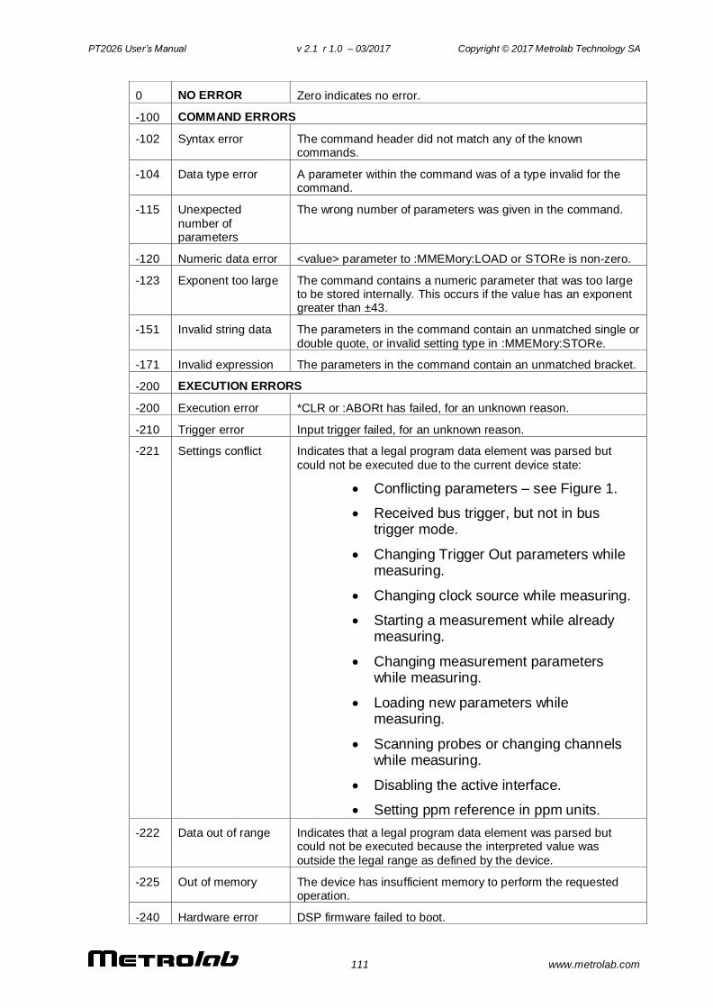
PT2026 User’s Manual v 2.1 r 1.0 – 03/2017 Copyright © 2017 Metrolab Technology SA
111 www.metrolab.com
0 NO ERROR Zero indicates no error.
-100 COMMAND ERRORS
-102 Syntax error The command header did not match any of the known commands.
-104 Data type error A parameter within the command was of a type invalid for the command.
-115 Unexpected
number of parameters
The wrong number of parameters was given in the command.
-120 Numeric data error <value> parameter to :MMEMory:LOAD or STORe is non-zero.
-123 Exponent too large The command contains a numeric parameter that was too large to be stored internally. This occurs if the value has an exponent greater than ±43.
-151 Invalid string data The parameters in the command contain an unmatched single or
double quote, or invalid setting type in :MMEMory:STORe.
-171 Invalid expression The parameters in the command contain an unmatched bracket.
-200 EXECUTION ERRORS
-200 Execution error *CLR or :ABORt has failed, for an unknown reason.
-210 Trigger error Input trigger failed, for an unknown reason.
-221 Settings conflict Indicates that a legal program data element was parsed but
could not be executed due to the current device state:
Conflicting parameters – see Figure 1.
Received bus trigger, but not in bus trigger mode.
Changing Trigger Out parameters while measuring.
Changing clock source while measuring.
Starting a measurement while already measuring.
Changing measurement parameters while measuring.
Loading new parameters while measuring.
Scanning probes or changing channels while measuring.
Disabling the active interface.
Setting ppm reference in ppm units.
-222 Data out of range Indicates that a legal program data element was parsed but could not be executed because the interpreted value was
outside the legal range as defined by the device.
-225 Out of memory The device has insufficient memory to perform the requested operation.
-240 Hardware error DSP firmware failed to boot.
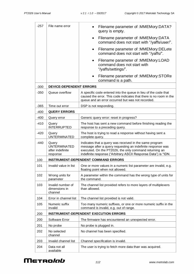
PT2026 User’s Manual v 2.1 r 1.0 – 03/2017 Copyright © 2017 Metrolab Technology SA
112 www.metrolab.com
-257 File name error Filename parameter of :MMEMory:DATA? query is empty.
Filename parameter of :MMEMory:DATA command does not start with “/yaffs/user/”.
Filename parameter of :MMEMory:DELete command does not start with “/yaffs/”.
Filename parameter of :MMEMory:LOAD command does not start with “/yaffs/settings/”.
Filename parameter of :MMEMory:STORe command is a path.
-300 DEVICE-DEPENDENT ERRORS
-350 Queue overflow A specific code entered into the queue in lieu of the code that
caused the error. This code indicates that there is no room in the queue and an error occurred but was not recorded.
-365 Time out error DSP is not responding.
-400 QUERY ERRORS
-400 Query error Generic query error: reset in progress?
-410 Query
INTERRUPTED
The host has sent a new command before finishing reading the
response to a preceding query.
-420 Query
UNTERMINATED
The host is trying to read a response without having sent a
complete query.
-440 Query UNTERMINATED after indefinite
response
Indicates that a query was received in the same program message after a query requesting an indefinite response was executed. On the PT2026, the only command returning an
indefinite response (“Arbitrary ASCII Response Data”) is *IDN.
100 INSTRUMENT-DEPENDENT COMMAND ERRORS
101 Invalid value in list One or more values in a numeric list parameter are invalid, e.g.
floating point when not allowed.
102 Wrong units for
parameter
A parameter within the command has the wrong type of units for
the command.
103 Invalid number of dimensions in channel
The channel list provided refers to more layers of multiplexers than allowed.
104 Error in channel list The channel list provided is not valid.
105 Numeric suffix invalid
Too many numeric suffixes, or one or more numeric suffix in the command is invalid, e.g. out of range.
200 INSTRUMENT-DEPENDENT EXECUTION ERRORS
200 Software Error The firmware has encountered an unexpected error.
201 No probe No probe is plugged in.
202 No selected
channel
No channel has been specified.
203 Invalid channel list Channel specification is invalid.
204 Data not all
available
The user is trying to fetch more data than was acquired.
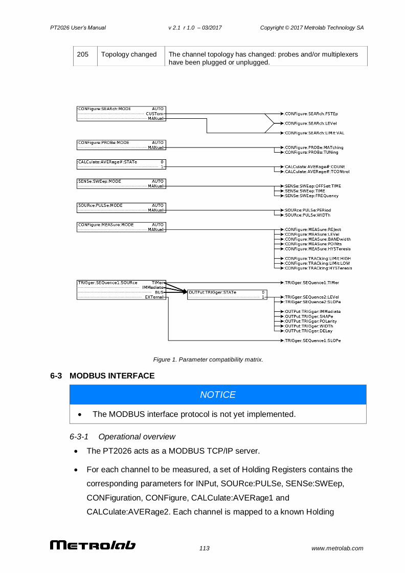
PT2026 User’s Manual v 2.1 r 1.0 – 03/2017 Copyright © 2017 Metrolab Technology SA
113 www.metrolab.com
Figure 1. Parameter compatibility matrix.
6-3 MODBUS INTERFACE
NOTICE
The MODBUS interface protocol is not yet implemented.
6-3-1 Operational overview
The PT2026 acts as a MODBUS TCP/IP server.
For each channel to be measured, a set of Holding Registers contains the
corresponding parameters for INPut, SOURce:PULSe, SENSe:SWEep,
CONFiguration, CONFigure, CALCulate:AVERage1 and
CALCulate:AVERage2. Each channel is mapped to a known Holding
205 Topology changed The channel topology has changed: probes and/or multiplexers
have been plugged or unplugged.
PT2026 User’s Manual v 2.1 r 1.0 – 03/2017 Copyright © 2017 Metrolab Technology SA
114 www.metrolab.com
Register address according to a well-defined channel map (see Section 6-3-
2).
The MODBUS module in the PT2026 will continuously scan the specified
channels. The results of these measurements consist of:
o the field value
o the standard deviation
o the time stamp.
These results are stored in a set of Input Registers, available at any time for
read-out. The Input Registers are mapped to channels in the same order as
the Holding Registers. Initially, the Input Registers will return a time stamp of
zero, allowing the host to determine whether a valid measurement is
available yet.
The Input Registers also contain the model and serial number of the attached
probe. By reading these, the host can determine which channels can be
activated.
Bit-access, via "Discrete Inputs" and "Coils," is not used.
Floating-point numbers are by default IEEE 64 bit format, and are mapped
onto four 16-bit MODBUS registers using the big-endian convention.
Optionally, they can be returned in IEEE 32 bit format; in this case, each
floating-point number is mapped into the 32 MSBs of the allotted 64-bit slot.
No assumption should be made concerning the contents of the unused 32
bits.
Integers are mapped onto a single 16-bit register.
The time stamp, indicating the end of the measurement, is an unsigned 32-bit
tick count, where each tick is a ms. It is mapped onto two 16-bit registers,
using the big-endian convention.
Strings – for example the probe model – are written into successive 16-bit
registers, using the big-endian convention, and are terminated by a null
character.
The MODBUS interface provides the following security features:
PT2026 User’s Manual v 2.1 r 1.0 – 03/2017 Copyright © 2017 Metrolab Technology SA
115 www.metrolab.com
o Other interfaces (VXI-11 and USBTMC) can be disabled. The
USBTMC interface will be automatically re-enabled upon power-up, to
avoid locking up an instrument completely.
o The PT2026 can be constrained to accept MODBUS commands only
from a limited set of IP addresses. This configuration option must be
set through the native interface.
o The number of simultaneous connections is limited, by default to one.
This parameter can be changed through the native interface.
Attempted connections that exceed this limit will be refused. Each
connection is maintained until terminated by the client.
A saved instrument configuration can be read out and written back via one of
the native interfaces. The output is an XML file that the PT2026 writes to
flash memory to save its state. Using this file, a clever programmer could also
automatically generate a SCADA configuration corresponding to the PT2026
configuration. Note, however, that the XML file is an undocumented internal
interface whose format may change in future releases of the firmware.
The following PT2026 features are not supported by the MODBUS interface:
o Control over the time of measurement – be it programmatically, via a
timer, via a bus trigger, or via the Trigger Input signal.
o Detailed status of each measurement
o Service requests (interrupts)
o Results in units other than Tesla
o Results in a format other than binary
o Reading the NMR signal
o Generating a Trigger Output signal
o Changing the Ethernet communications parameters
o Firmware upgrades
Note that all these features continue to be available via the native VXI-11 or
USBTMC interfaces.
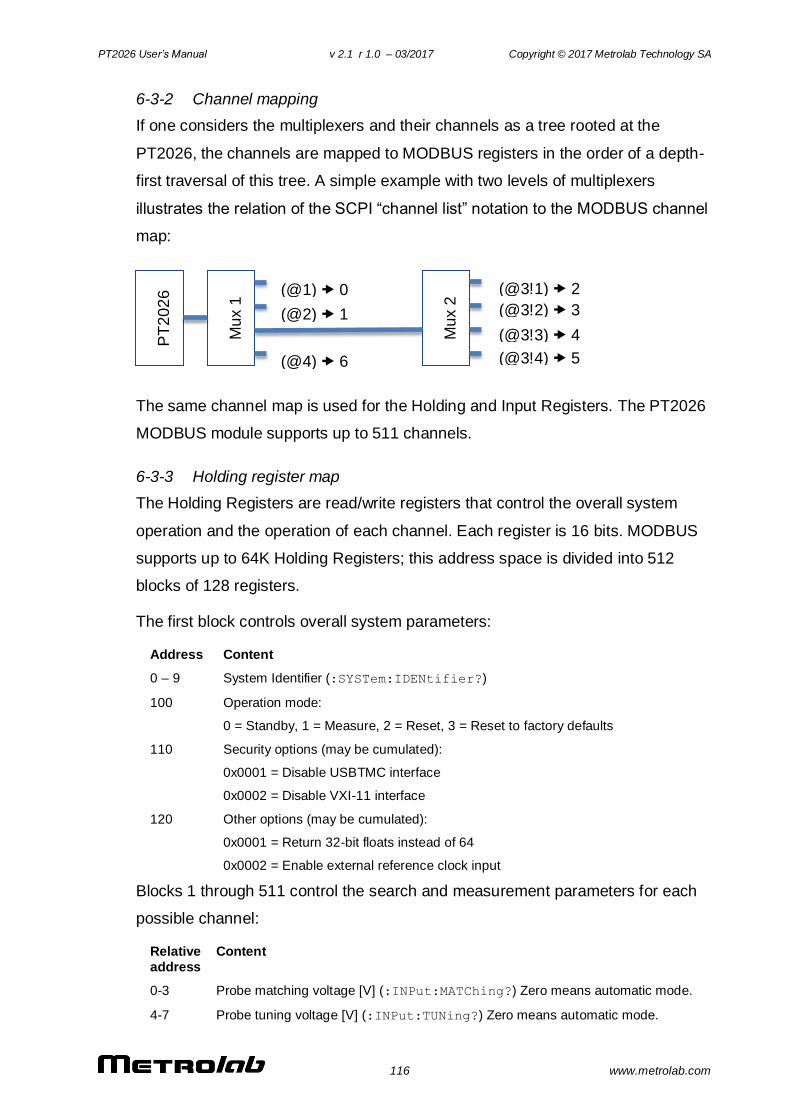
PT2026 User’s Manual v 2.1 r 1.0 – 03/2017 Copyright © 2017 Metrolab Technology SA
116 www.metrolab.com
6-3-2 Channel mapping
If one considers the multiplexers and their channels as a tree rooted at the
PT2026, the channels are mapped to MODBUS registers in the order of a depth-
first traversal of this tree. A simple example with two levels of multiplexers
illustrates the relation of the SCPI “channel list” notation to the MODBUS channel
map:
The same channel map is used for the Holding and Input Registers. The PT2026
MODBUS module supports up to 511 channels.
6-3-3 Holding register map
The Holding Registers are read/write registers that control the overall system
operation and the operation of each channel. Each register is 16 bits. MODBUS
supports up to 64K Holding Registers; this address space is divided into 512
blocks of 128 registers.
The first block controls overall system parameters:
Address Content
0 – 9 System Identifier (:SYSTem:IDENtifier?)
100 Operation mode:
0 = Standby, 1 = Measure, 2 = Reset, 3 = Reset to factory defaults
110 Security options (may be cumulated):
0x0001 = Disable USBTMC interface
0x0002 = Disable VXI-11 interface
120 Other options (may be cumulated):
0x0001 = Return 32-bit floats instead of 64
0x0002 = Enable external reference clock input
Blocks 1 through 511 control the search and measurement parameters for each
possible channel:
Relative
address
Content
0-3 Probe matching voltage [V] (:INPut:MATChing?) Zero means automatic mode.
4-7 Probe tuning voltage [V] (:INPut:TUNing?) Zero means automatic mode.
PT
20
26
Mux 1
Mux 2
(@1) 0
(@2) 1
(@4) 6
(@3!1) 2
(@3!2) 3
(@3!3) 4
(@3!4) 5
PT2026 User’s Manual v 2.1 r 1.0 – 03/2017 Copyright © 2017 Metrolab Technology SA
117 www.metrolab.com
8-11 Pulse frequency [Hz] (:SOURce:PULSe:FREQuency?) Zero means automatic
mode.
12-15 Pulse width [s] (:SOURce:PULSe:WIDTh?) Zero means automatic mode.
16-19 Acquisition sweep time [s] (:SENSe:SWEep:TIME?) Zero means automatic mode.
20-23 Acquisition rate [Hz] (:SENSe:SWEep:FREQuency?)
24-27 Acquisition offset [s] (:SENSe:SWEep:OFFSet:TIME?)
28-31 Search threshold (CONFigure:SEARch:LEVel?)
32-35 Search frequency step (CONFigure:SEARch:FSTEp?) Zero means default value.
36-39 Search lower limit [UNIT?] (CONFigure:SEARch:LIMit:LOW?) Zero means
default value.
40-43 Search upper limit [UNIT?] (CONFigure:SEARch:LIMit:HIGH?) Zero means
default value.
44-47 Search manual value [UNIT?] (CONFigure:SEARch:LIMit:VALue?)
48-51 Measurement threshold (CONFigure:MEASure:LEVel?)
52-55 Analysis bandwidth (CONFigure:MEASure:BANDwidth?)
56-59 Minimum IF for tracking [Hz] (CONFigure:TRACking:LOW?)
60-63 Maximum IF for tracking [Hz] (CONFigure:TRACking:HIGH?)
100 Search mode (CONFigure:SEARch:MODE?)
0 = Auto, 1 = Custom, 2 = Manual
101 Frame size (CONFigure:MEASure:FRAMe?)
102 Number of analysis points (CONFigure:MEASure:POINts?)
103 Signal averaging enable (:CALCulate:AVERage1:STATe?):
0 = Disable; 1 = Enable
104 Signal averaging termination control (:CALCulate:AVERage1:TCONtrol?):
1 = EXPonential, 2 = REPeat
105 Signal averaging count (:CALCulate:AVERage1:COUNt?)
106 Measurement averaging enable (:CALCulate:AVERage1:STATe?):
0 = Disable; 1 = Enable
107 Measurement averaging termination control (:CALCulate:AVERage2:TCONtrol?):
1 = EXPonential, 2 = REPeat, 3 = MOVing
108 Measurement averaging count (:CALCulate:AVERage2:COUNt?)
109 Hysteresis for tracking (CONFigure:TRACking:HYSTeresis?)
127 Channel state: 0 = Not present, 1 = Disabled, 2 = Enabled
6-3-4 Input Register Map
The Input Registers are read-only registers that provide information about the
system as a whole and about each channel, including the measurement results.
Each register is 16 bits. MODBUS supports up to 64K Input Registers; this
address space is divided into 512 blocks of 128 registers.
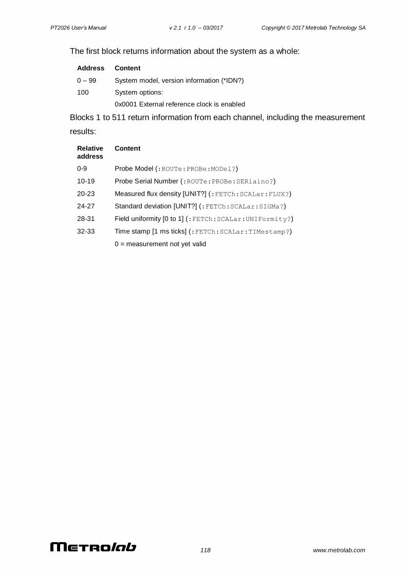
PT2026 User’s Manual v 2.1 r 1.0 – 03/2017 Copyright © 2017 Metrolab Technology SA
118 www.metrolab.com
The first block returns information about the system as a whole:
Address Content
0 – 99 System model, version information (*IDN?)
100 System options:
0x0001 External reference clock is enabled
Blocks 1 to 511 return information from each channel, including the measurement
results:
Relative
address
Content
0-9 Probe Model (:ROUTe:PROBe:MODel?)
10-19 Probe Serial Number (:ROUTe:PROBe:SERialno?)
20-23 Measured flux density [UNIT?] (:FETCh:SCALar:FLUX?)
24-27 Standard deviation [UNIT?] (:FETCh:SCALar:SIGMa?)
28-31 Field uniformity [0 to 1] (:FETCh:SCALar:UNIFormity?)
32-33 Time stamp [1 ms ticks] (:FETCh:SCALar:TIMestamp?)
0 = measurement not yet valid
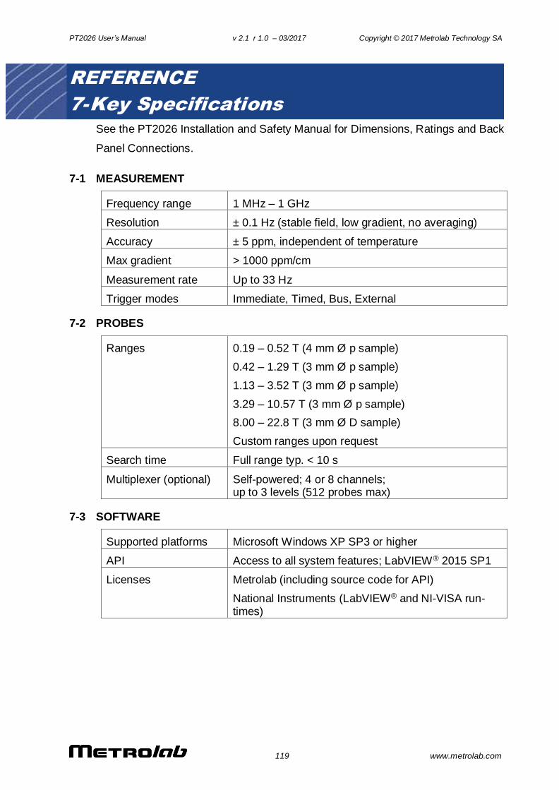
PT2026 User’s Manual v 2.1 r 1.0 – 03/2017 Copyright © 2017 Metrolab Technology SA
119 www.metrolab.com
REFERENCE
7- Key Specifications
See the PT2026 Installation and Safety Manual for Dimensions, Ratings and Back
Panel Connections.
7-1 MEASUREMENT
Frequency range 1 MHz – 1 GHz
Resolution ± 0.1 Hz (stable field, low gradient, no averaging)
Accuracy ± 5 ppm, independent of temperature
Max gradient > 1000 ppm/cm
Measurement rate Up to 33 Hz
Trigger modes Immediate, Timed, Bus, External
7-2 PROBES
Ranges 0.19 – 0.52 T (4 mm Ø p sample)
0.42 – 1.29 T (3 mm Ø p sample)
1.13 – 3.52 T (3 mm Ø p sample)
3.29 – 10.57 T (3 mm Ø p sample)
8.00 – 22.8 T (3 mm Ø D sample)
Custom ranges upon request
Search time Full range typ. < 10 s
Multiplexer (optional) Self-powered; 4 or 8 channels; up to 3 levels (512 probes max)
7-3 SOFTWARE
Supported platforms Microsoft Windows XP SP3 or higher
API Access to all system features; LabVIEW® 2015 SP1
Licenses Metrolab (including source code for API)
National Instruments (LabVIEW® and NI-VISA run-times)
PT2026 User’s Manual v 2.1 r 1.0 – 03/2017 Copyright © 2017 Metrolab Technology SA
120 www.metrolab.com
REFERENCE
8- NMR Magnetometers
(This section is adapted from an article published in Magnetics Technology
International 2011, pp. 78-71.)
Amongst a dozen physical phenomena exploited to measure magnetic field
strength, NMR (Nuclear Magnetic Resonance) is by far the most accurate. In
addition, NMR magnetometers are immune to temperature- or age-related drift.
For these reasons, they are widely used as a reference for calibrating other
magnetometers, such as the common Hall “gaussmeter.” However, due to
technological constraints, their use beyond calibration has been limited to
research and a few industrial applications. This may start to change. We review
the principles of operation of NMR magnetometers, their benefits and constraints,
and recent developments that aim to bring these fantastic instruments into more
common use.
8-1 NMR: A DISCOVERY DESTINED FOR GREATNESS
Building on fifty years of physics research, Nuclear Magnetic Resonance (NMR)
was experimentally demonstrated in late 1945 by two independent teams, led by
Felix Bloch at Stanford and Edward Purcell at Harvard. Bloch and Purcell received
the Nobel Prize in 1952, but industrialization of NMR had already started in 1948,
when Russel Varian, a colleague of Bloch’s, founded his company to use NMR for
chemical analyses. NMR spectrometers are now an essential tool in chemistry.
Similarly, Magnetic Resonance Imaging (MRI), first commercialized in 1978, has
quickly developed into one of medicine’s most important imaging modalities.
Commercial NMR magnetometers became available about the same time as MRI.
The principle is straightforward: if a nucleus has spin, it will act like a little
compass needle and align itself in a magnetic field. Quantum-mechanically
speaking, the nucleus has two energy states: the lower-energy state where the
nuclear magnetic moment is aligned with the external field, and the higher-energy
state where it is opposed. The gap between these two energy states depends
only on the magnitude of the magnetic moment and that of the magnetic field.
Since the nuclear magnetic moment is a constant, this energy gap is a perfect
measure of magnetic field strength.

PT2026 User’s Manual v 2.1 r 1.0 – 03/2017 Copyright © 2017 Metrolab Technology SA
121 www.metrolab.com
Figure 2. Principles of NMR.
As in spectroscopy, injecting just the right amount of energy will cause the
nucleus to transition from the lower to higher energy level. The injected energy is
proportional to its frequency, so a magnetic measurement via NMR consists of
searching for the frequency – the resonant frequency – that cause the nuclear
spins to flip.
The energy is injected by an AC magnetic field (usually called B1), perpendicular
to the field being measured (B0). Just like the angular momentum vector of a
spinning top precesses around the direction of gravity, the nuclear magnetic
moment precesses around B0; resonance occurs when the frequency of B1
exactly matches the precession, or Larmor, frequency. At resonance, B1 rotates
the spin away from B0 – even though B1 is generally orders of magnitude smaller
than B0.
8-2 THE INGREDIENTS FOR AN NMR MAGNETOMETER
Practically speaking, an NMR magnetometer has five main elements:
NMR sample: The sample material must have a nuclear spin; many common
isotopes, such as 12C or 16O, have zero spin and are transparent to NMR.
The material must also exhibit a sharp resonance; in a molecule, the NMR
resonance is broadened by interactions with the other nuclei and electrons.
Finally, the nuclei must “relax” to their initial, spin-aligned state in a
“reasonable” amount of time: too short a relaxation time prevents us from
detecting the resonance, but too long renders repeated measurements more
E
B0
p
p
Resonance: ω0 = γ B
0 ~ Larmor freq.
Quantum-mechanical view:
Energy level transition
Pseudo-classical view:
Spin precession
B1
B1
B0 M’
Resonance: ω0 = γ B
0 ~ ∆E
∆E
PT2026 User’s Manual v 2.1 r 1.0 – 03/2017 Copyright © 2017 Metrolab Technology SA
122 www.metrolab.com
difficult. The most readily available sample material is water (NMR resonance
of 1H, or proton).
B1 excitation coil: The B1 coil must be perpendicular to the field being
measured – more or less. Unlike Hall magnetometers, imperfect alignment
does not change the measurement result; it simply reduces the effective B1,
causing some loss of sensitivity.
RF generator: The key parameters are bandwidth (≈ 1 MHz to 1 GHz for 1H),
stability (≈ ppb/day), and suppression of spurious frequencies (<≈ -80 dB).
Producing such a generator economically is one of the major challenges in
designing an NMR magnetometer.
Detector: Various techniques exist to detect the NMR resonance:
o Marginal oscillator: the B1 coil is part of a marginally stable oscillator.
At resonance, the NMR sample absorbs energy, acting like a
resistance, thus lowering the Q and killing the oscillation.
o Continuous wave (CW): because of the same resistance-like effect,
the driving voltage on the B1 coil dips slightly at resonance. An
alternate CW technique is the inductive bridge, where a pick-up coil
perpendicular to the B1 coil detects when, at resonance, spins are
rotated by 90°.
o Pulsed-wave (PW): the sample is excited with a short, wide-band
pulse applied to the B1 coil; then, in a second step, the B1 coil is used
to detect the Larmor precession during the relaxation time.
Modulator: All but the PW technique require some sort of modulation, to
detect a change when crossing the resonance. The most obvious solution is
to modulate the frequency, but it is often more practical to add a small coil to
modulate B0, taking care to synchronize the measurement with the
modulation zero-crossing.
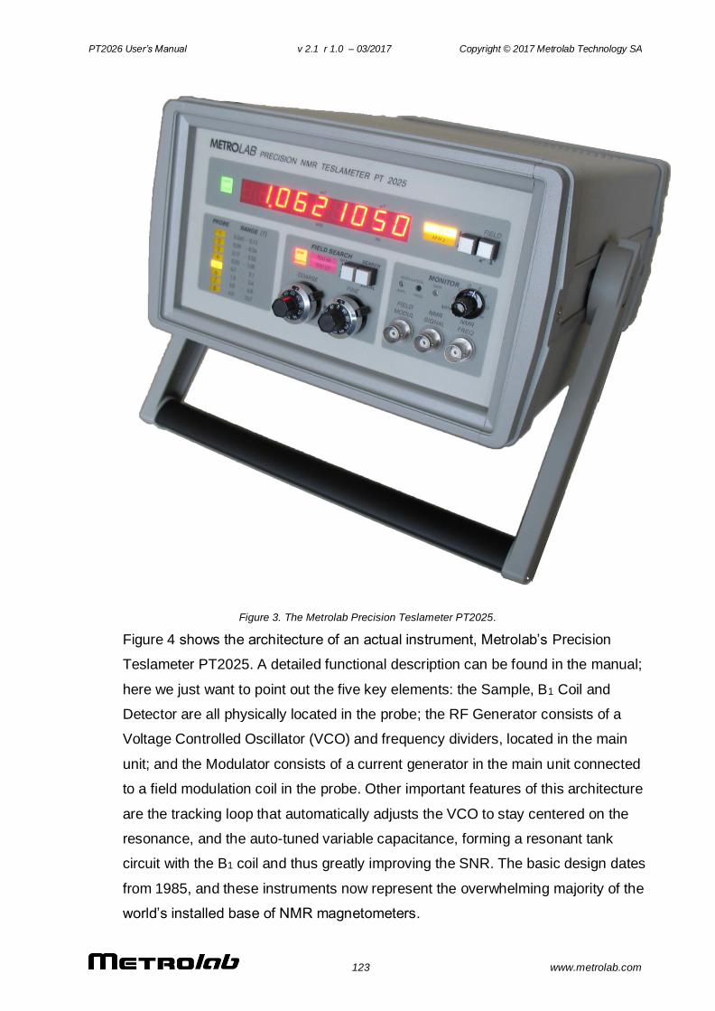
PT2026 User’s Manual v 2.1 r 1.0 – 03/2017 Copyright © 2017 Metrolab Technology SA
123 www.metrolab.com
Figure 3. The Metrolab Precision Teslameter PT2025.
Figure 4 shows the architecture of an actual instrument, Metrolab’s Precision
Teslameter PT2025. A detailed functional description can be found in the manual;
here we just want to point out the five key elements: the Sample, B1 Coil and
Detector are all physically located in the probe; the RF Generator consists of a
Voltage Controlled Oscillator (VCO) and frequency dividers, located in the main
unit; and the Modulator consists of a current generator in the main unit connected
to a field modulation coil in the probe. Other important features of this architecture
are the tracking loop that automatically adjusts the VCO to stay centered on the
resonance, and the auto-tuned variable capacitance, forming a resonant tank
circuit with the B1 coil and thus greatly improving the SNR. The basic design dates
from 1985, and these instruments now represent the overwhelming majority of the
world’s installed base of NMR magnetometers.
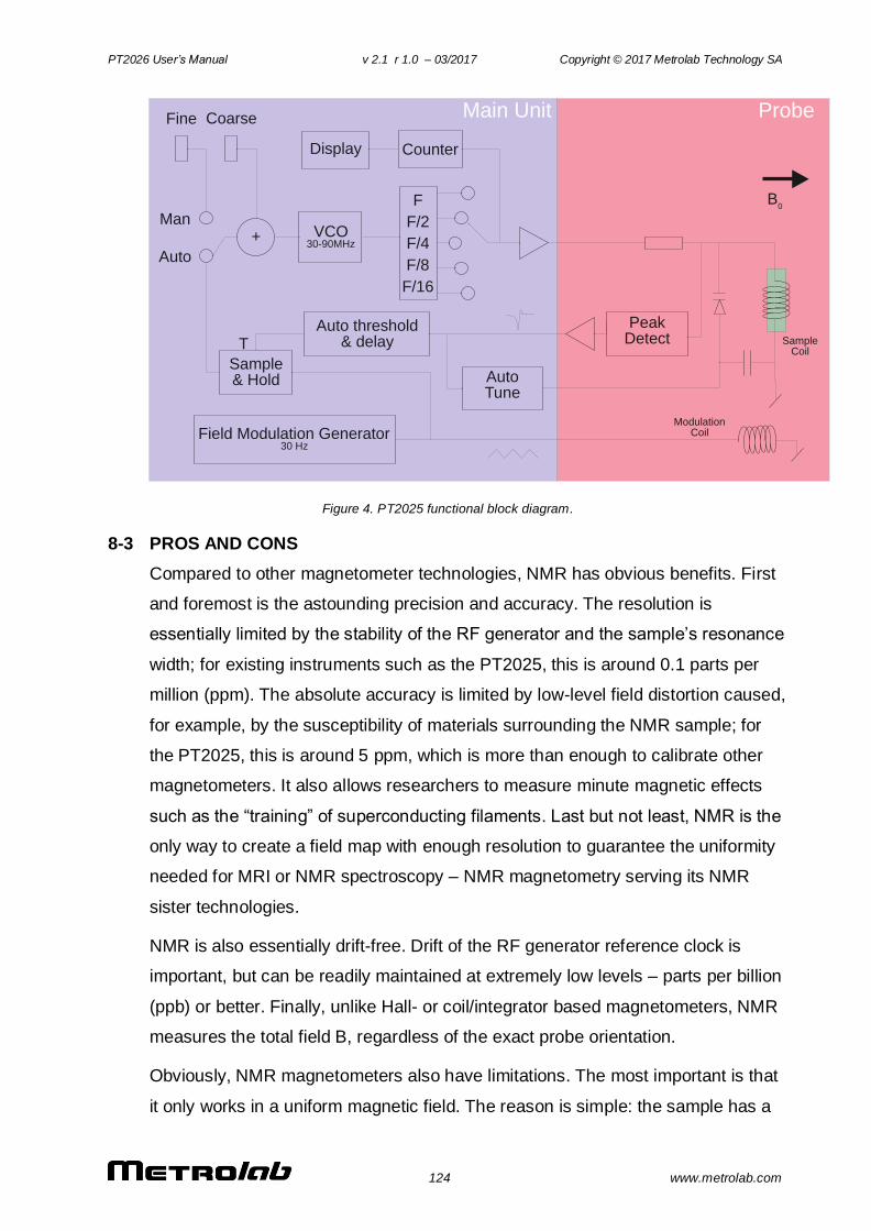
PT2026 User’s Manual v 2.1 r 1.0 – 03/2017 Copyright © 2017 Metrolab Technology SA
124 www.metrolab.com
Figure 4. PT2025 functional block diagram.
8-3 PROS AND CONS
Compared to other magnetometer technologies, NMR has obvious benefits. First
and foremost is the astounding precision and accuracy. The resolution is
essentially limited by the stability of the RF generator and the sample’s resonance
width; for existing instruments such as the PT2025, this is around 0.1 parts per
million (ppm). The absolute accuracy is limited by low-level field distortion caused,
for example, by the susceptibility of materials surrounding the NMR sample; for
the PT2025, this is around 5 ppm, which is more than enough to calibrate other
magnetometers. It also allows researchers to measure minute magnetic effects
such as the “training” of superconducting filaments. Last but not least, NMR is the
only way to create a field map with enough resolution to guarantee the uniformity
needed for MRI or NMR spectroscopy – NMR magnetometry serving its NMR
sister technologies.
NMR is also essentially drift-free. Drift of the RF generator reference clock is
important, but can be readily maintained at extremely low levels – parts per billion
(ppb) or better. Finally, unlike Hall- or coil/integrator based magnetometers, NMR
measures the total field B, regardless of the exact probe orientation.
Obviously, NMR magnetometers also have limitations. The most important is that
it only works in a uniform magnetic field. The reason is simple: the sample has a
ProbeMain UnitFine Coarse
Man
Auto
+ VCO30-90MHz
F
F/2
F/4
F/8
F/16
Display Counter
PeakDetect
AutoTune
Auto threshold& delay
Field Modulation Generator30 Hz
Sample& Hold
SampleCoil
ModulationCoil
B0
T

PT2026 User’s Manual v 2.1 r 1.0 – 03/2017 Copyright © 2017 Metrolab Technology SA
125 www.metrolab.com
finite size (≈ 4 mm diameter); a magnetic field gradient causes one end of the
sample to resonate at a different frequency than the other, and the higher the
gradient, the harder it becomes to determine “the” resonant frequency. Today’s
limit is a field gradient on the order of 100 to 1000 ppm/cm. Most magnets are
very far from this level of field uniformity.
Since NMR is a relatively slow technology – on the order of 10 to 100 ms per
measurement – it is of limited use for rapidly varying fields. Finally, the field needs
to be relatively strong for the spin-flip energy gap to rise significantly above the
room temperature thermal noise. For example, the range of PT2025 probes starts
at 40 mT, or roughly 1000x the earth’s field. Sadly, many interesting and useful
applications fall into that three-order-of-magnitude “NMR no-fly zone.”
NMR magnetometers have continued to evolve since 1985. Many changes simply
follow industry trends in terms of electronic components, microprocessors,
displays, controls and computer interfaces. However, some improvements allow
us to push back key limitations, opening the way for a more widespread use of
NMR magnetometers. Let us take a look at some of these.
8-4 MORE IS BETTER
The first major step came in 1992, with the introduction of multi-probe systems for
mapping MRI magnets – what eventually became Metrolab’s Magnetic Field
Camera MFC3045. Up to 32 NMR probes functioning in parallel addressed the
need for faster field maps. Other key improvements include the use of a Direct
Digital Synthesizer (DDS) as RF Generator, which allows using frequency
modulation and eliminating the field modulation coils. Also, the auto-tuning circuit
with a varactor diode was replaced with a simple trim cap, reducing the
measurement range from 300% per probe for the PT2025 to around ±2% – a
perfectly acceptable simplification for MRI magnets, where the target field is
exactly known. Finally, the mechanical aspects of the instrument were optimized
for MRI production, with robust housing and connectors, remote control, etc.

PT2026 User’s Manual v 2.1 r 1.0 – 03/2017 Copyright © 2017 Metrolab Technology SA
126 www.metrolab.com
Figure 5. The Magnetic Field Camera probe array: (a) cut-away showing the probe positions; (b) as installed in a horizontal MRI magnet.
With this instrument, the time to map a magnet was reduced from many hours to
around five minutes. Productivity gains add to technical benefits: less magnet drift
and fewer human errors, combined with improved positioning precision, meant
more self-consistent maps and better convergence of the entire magnet-tuning
process. It is fair to say that without the development of multi-probe NMR
systems, MRI would not be what it is today.
8-5 BETTER IS BETTER
For almost a decade, Metrolab has been working on a new-generation, “all digital”
NMR magnetometer, the PT2026. As we can see from Figure 6, the term “all
digital” is to be taken with a grain of salt: “all digital control” is more accurate.
Other important technical improvements include:
RF Generator: up to around 1 GHz, instead of 90 MHz for the PT2025.
Absolute frequency control simplifies the architecture and improves
stability.
Detection: support for either continuous-wave (CW, like PT2025) or
pulsed-wave (PW, as shown in Figure 6). Improved performance in poor-
SNR environments due to sophisticated Digital Signal Processing (DSP).
Modulation: field modulation for CW probes, or none for PW probes.
Multi-probe capability: up to 512 PW channels, or 16x the MFC3045.
Probe tuning: variable, like PT2025, or fixed, like MFC3045. For PW
probes, dynamic matching improves power transfer.
Search of NMR resonance: assisted by 3-axis Hall probe.
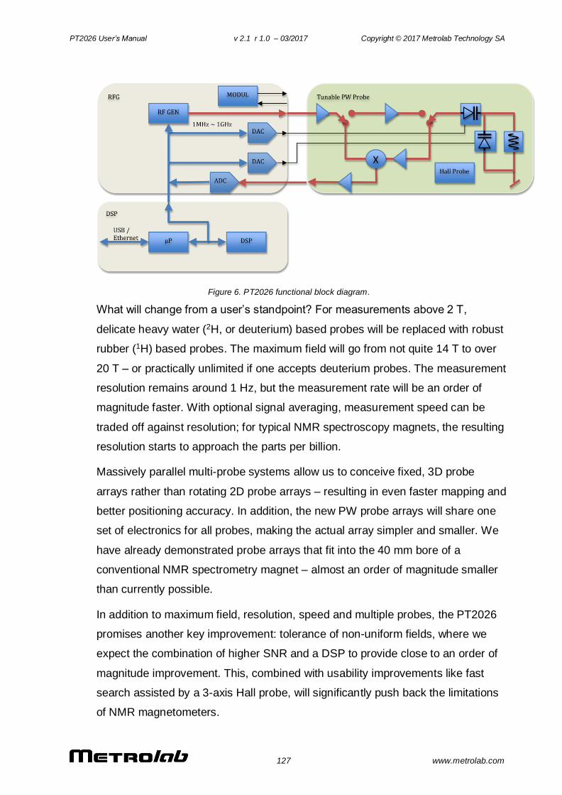
PT2026 User’s Manual v 2.1 r 1.0 – 03/2017 Copyright © 2017 Metrolab Technology SA
127 www.metrolab.com
Figure 6. PT2026 functional block diagram.
What will change from a user’s standpoint? For measurements above 2 T,
delicate heavy water (2H, or deuterium) based probes will be replaced with robust
rubber (1H) based probes. The maximum field will go from not quite 14 T to over
20 T – or practically unlimited if one accepts deuterium probes. The measurement
resolution remains around 1 Hz, but the measurement rate will be an order of
magnitude faster. With optional signal averaging, measurement speed can be
traded off against resolution; for typical NMR spectroscopy magnets, the resulting
resolution starts to approach the parts per billion.
Massively parallel multi-probe systems allow us to conceive fixed, 3D probe
arrays rather than rotating 2D probe arrays – resulting in even faster mapping and
better positioning accuracy. In addition, the new PW probe arrays will share one
set of electronics for all probes, making the actual array simpler and smaller. We
have already demonstrated probe arrays that fit into the 40 mm bore of a
conventional NMR spectrometry magnet – almost an order of magnitude smaller
than currently possible.
In addition to maximum field, resolution, speed and multiple probes, the PT2026
promises another key improvement: tolerance of non-uniform fields, where we
expect the combination of higher SNR and a DSP to provide close to an order of
magnitude improvement. This, combined with usability improvements like fast
search assisted by a 3-axis Hall probe, will significantly push back the limitations
of NMR magnetometers.
PT2026 User’s Manual v 2.1 r 1.0 – 03/2017 Copyright © 2017 Metrolab Technology SA
128 www.metrolab.com
8-6 EVEN LESS CAN BE BETTER
The PT2026 leaves one major barrier untouched: that for fields below 40 mT.
There are four basic approaches to address this problem:
Larger sample: provides more nuclei and thus a better SNR. However, the
large probe size is a great practical hindrance.
Electron-Spin Resonance (ESR): very similar to NMR, except based on
electron spin instead of nuclear spin, with a gyromagnetic ratio in the
GHz/T instead of the MHz/T. Currently known ESR probe materials are
chemically unstable and/or have wide resonance widths, making them
unsuitable for an industrial instrument.
Pre-polarization: improve the SNR by aligning the spins in a strong magnet
before measuring the resonance in the weak field. Requires physically
transporting the sample material – for example water – from the
polarization magnet to the B1 coil.
Higher pick-up sensitivity: replace the coil with a more sensitive pick-up,
such as a superconducting coil or Superconducting Quantum Interference
Device (SQUID).
In the past, Metrolab has shipped PT2025 probes with large samples and with
ESR samples; neither proved to be entirely satisfactory. Metrolab is now pursuing
the third option, a flowing water system, specifically for calibrating Hall probes
over a wide range of fields (±2 T) with a single probe. We also continue to search
for innovative ESR sample materials. High-sensitivity pickups may be a promising
long-term solution, but the technological complexity is currently daunting.
Metrolab earned their dominant position in NMR magnetometry by making a
delicate piece of laboratory equipment work in the rough-and-tumble
manufacturing environment. Our equipment goes from the arctic cold of an
airplane hold to the sauna-like Singapore summer, gets dropped by the baggage
handlers, yanked into place by a burly technician pulling on the probe cable – and
is then expected to deliver parts-per-million accuracy. More than twenty years
later, such systems are still returned for calibration (and occasionally, repair). We
are committed to continuing to push back the limitations as far as physics and
good engineering allow.